Presents the following instructional slide show:
|
|
|
- Arron Greer
- 5 years ago
- Views:
Transcription


1 Presents the following instructional slide show:
2 Operating Procedures for the Sure Shot Acoustic Fluid Level System.


3 Sure Shot Acoustic Fluid Level System Well head attachment and accessories Complete Sure Shot System
4 Table of Contents Purpose of Performing a Fluid Level Slide 5 Fluid Level Techniques Slides 6-76 Fluid Level Procedure Shooting a Fluid Level Slides Different Methods of Creating a Sound Wave Implode Slides 21 Explode Slides 22 Counting a fluid level Counting Collars Slides
5 Purpose of Performing a Fluid Level A fluid level is the distance from the surface (wellhead) to the gas-liquid interface. An accurate fluid level is used for the following purposes: Estimate bottom-hole pressure Evaluate pump performance Determine additional production; and Assess operating changes
6 Fluid Level Techniques The Sure Shot system consists of a digital sound processor and a well head attachment which includes a sound generator and a sensor (microphone). The sound generator is used to create a sound wave by discharging a blank cartridge or compressed gas into the casing, or in some situations the tubing. The sound can also be generated by releasing the annulus gas into the empty chamber.
7 The sound wave travels down the annulus from surface until it reaches the gas-liquid interface and is then reflected back to the surface. Upon returning to the surface, the sound wave is sensed by the microphone and then relayed to the processor. After the filtering and amplifying process, the processor receives the signal and sends it to the laptop. The depth of the fluid level is determined by reference to obstructions in the annulus space such as tubing joints (collars), anchor, liner, perforations etc.
8 Fluid Level Procedures 1. If at any time during the Sure Shot fluid level procedure you feel that yours or anyone else's safety is at risk please stop all operations until the situation has been resolved. 2. Contact operator to inform them on what work you will be carrying out, as a work permit may be required. 3. Always be sure to wear your Personal Protective Equipment (PPE) including steel toed boots (sneaker style not recommended), hard hat, gloves, safety glasses, 4 gas monitor, and coveralls.

9 4. Locate the well that needs to be tested using the Legal Land Description (LLD). 5. Park vehicle at least 3.5 meters upwind from the well. 6. Open the Single Shot program on the laptop; go to File, New or Ctrl N. This will bring up a blank sheet with comments in the upper left hand corner.
10 7. Go to Edit, then Comments; the Sure Shot fluid level information dialog box will appear. Begin by entering in the company name, surface and down hole locations, and the field name.
11 8. Take the tubing pressure and record this value in the corresponding field in the Sure Shot fluid level information dialog box. 9. Observe the casing pressure as this will help to determine what method should be used to generate the sound wave i.e. blank shell, CO2,, nitrogen, or implode.

12 10. If necessary, fill in comments in the large blank area on the Sure Shot fluid level information dialog box. Things that are unusual go here, such as the stuffing box leaking, well tapping, beam compressor setups etc. Once the comments have been filled out click okay at the bottom of the Sure Shot fluid level information dialog box.

13 11. Using the Sure Shot Sure Shot Gun gun tie into the casing. To decide where to tie into, examine the set up of the well. The Sure Shot gun cannot shoot through check valves, needle valves, or any hole less than ¼ inch in diameter. The tie in spot should be easy to isolate and should have a one way path to the casing. A nipple with a 90 elbow or a different size swedge may be required. Note: Ensure the well pressure is below the Sure Shot gun ratings (must not exceed 3000psi using gas charges, 1000psi using black powder).


14 12. Connect the microphone cable to the microphone and the Sure Shot processor. Turn on the processor and make sure the LED starts to blink. Connect the data cable to the Microphone Sure Shot Processor Microphone Cable Laptop computer and the Sure Shot processor. Make sure the power inverter is turned off. Also be sure to refrain from disturbing the microphone cable as it will pick up exterior noise.
 should now be running across the screen.")
15 13. Go to Com and then Connect; the fluid line (green) and collar line (red) should now be running across the screen. Com button

16 14. The sensitivity of the processor can also be adjusted to filter out the noise by adjusting the fluid and collar line dials on the Sure Shot processor.
17 15. When ready for the shot, press the record button on the screen and discharge the sound wave into the annulus. The fluid and the collar lines should jump at the same time on the computer screen indicating the beginning Record button of the shot. Watch the screen for the fluid response (kick). Keep recording and Beginning Fluid Response watch for the of shot (Kick) Repeat repeat of the kick.
18 16. Once the repeat of the kick has been seen click record again to stop recording. A fluid level has now been successfully taken. Note: With wells that are fueled by annulus gas, the casing valve that leads to the gas motor will have to be opened after every shot to ensure the motor does not shut down.
19 17. If no more fluid levels are required, the Sure Shot system may now be taken off the well. 18. Prevent oil from spilling when removing the gun and always be sure to leave the well the same way it was upon arriving.
20 Different Methods of Generating a Sound Wave
21 Implode The implode method utilizes the casing pressure to create a differential pressure in the Sure Shot gun, thus allowing a sound wave to be created. The implode method can be used when: Well pressure is high (above 700 psi) Well is quiet, as the sound wave is not as distinct when using the implode method
22 Explode The explode method uses an alternate pressure source (blank cartridge/compressed gas) to create the sound wave. The following observations should be noted before using the various methods of explode. Blank Shells -must be approved by the owner of the well -there must be a positive casing pressure -well pressure must not exceed 1000psi -the well must be free of oxygen Compressed Gas -well pressure must not exceed 3000psi
23 Counting Fluid Levels
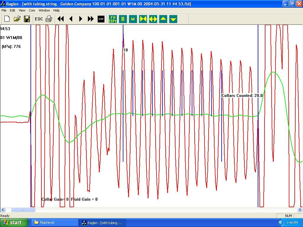
24 Total of 23.8 Joints to Fluid Level Total 23.8 Joints to fluid Level Beginning of Shot Fluid Response (Kick) Repeat
25 1. To count the number of joints to the fluid, scroll to the beginning of the shot and click the left mouse button to mark the beginning of the shot. A vertical blue line will appear at this point (see chart on the previous slide).
26 2. Scroll forward to the fluid response (kick) and click the right mouse button to mark the kick; a vertical blue line will appear at this point. Continue scrolling and a blue line will automatically appear at the repeat of the kick (see chart on the previous slide). Note: To ensure that the beginning of the shot and the kick are marked correctly, print the fluid level strip and fold it at the kick; the beginning and the repeat of the fluid level should line up.

27 3. Now click on button B to position the 11Pt divider at the beginning of the shot. The width of the divider may need to be adjusted by using the left and right arrow buttons. The vertical position of the divider may 11Pt Divider also need to be adjusted by using the up and down arrow buttons at the top of the screen.

28 4. When collar responses are poor, a section of the fluid level with good collar responses may need to be located in order to adjust the divider accurately. Place the divider on the collars by clicking on the Fit 11 Pt button and then click on the collar that the divider should be placed on. The divider may need to be adjusted to line up with the collars. When the divider has been Fit 11 Pt button adjusted, click on the B button to move the divider to the beginning of the fluid level.
29 5. Click the M button to move the divider along the fluid level (see photo A on next slide). Continue clicking until the kick has been reached. The divider width may have to be adjusted when moving along. As the divider moves along the fluid level, the number of joints counted will appear at the top of the screen. Upon reaching the kick, the total number of joints to fluid will appear (see photo B on the next slide).

30 Picture A Picture B
31 DO NOT HESITATE TO CONTACT NELGAR IF YOU ARE UNSURE OR HAVE ANY QUESTIONS.
Acoustic Troubleshooting of Coal Bed Methane Wells
 Gas Well Deliquification Workshop Sheraton Hotel, February 29 March 2, 2016 Acoustic Troubleshooting of Coal Bed Methane Wells O. Lynn Rowlan and Dieter Becker lynn@echometer.com Introduction Distance
Downhole Gas Separators
 Gas Well De-Liquification Workshop Denver, Colorado February 27 March1, 2006 Downhole Gas Separators A Laboratory and Field Study Jim McCoy, Echometer Company Tony Podio, University of Texas at Austin
Acoustic Liquid Level Testing of Gas Wells
 European Conference Gas Well Deliquification 28-30 September 2009, Hampshire Hotel, The Netherlands Acoustic Liquid Level Testing of Gas Wells Originally Presented OKC POS 2009 - SPE 120643 Lynn Rowlan
NR-Tec Ltd. S2S SMARTSHOT Acoustic Fluid Level Instrument
 NR-Tec Ltd. S2S SMARTSHOT Acoustic Fluid Level Instrument The S2S SmartShot is a single shot, manually operated fluid level instrument with next generation SmartShot Technology. This new technology enhances
Old Kings Oval Electronic Scoreboard. Scoreboard Operation and Advanced Scoring Instructions
 Old Kings Oval Electronic Scoreboard Scoreboard Operation and Advanced Scoring Instructions 1 Introduction... 3 Primary Contacts... 3 Solid Scoreboards 24/7 Support 0458 LED FIX (0458 533 349)Scoring a
TROUBLESHOOT ROD PUMPED WELLS USING TUBING FLUID LEVEL SHOTS
 10 th Annual Sucker Rod Pumping Workshop Renaissance Hotel Oklahoma City, Oklahoma September 16-19, 2014 TROUBLESHOOT ROD PUMPED WELLS USING TUBING FLUID LEVEL SHOTS John Sparks, COG OPERATING LLCU Lynn
Instructions for Use
 Select-380 T-Auto T-Auto Contents Page Instructions for Use Ref: 3.0 IFU 380 T-Auto Mar 18 2 Schematic layout of the doser 3 Quick-fit instructions 4 Description/Installation/Operation Pump tubes & Water
SPLIT HOPKINSON PRESSURE BAR OPERATIONS MANUAL 5/9/2014
 B Calibration of Split Hopkinson Pressure Bar Setup: Calibration is performed by comparing the wave speed of the initial pulse versus the reflected pulse and calculating the Energy Ratio. This ratio gives
Well Testing Plan. New York Marginal Well Study. Introduction. I. Tests to be Conducted. II. Testing Procedures
 Well Testing Plan New York Marginal Well Study Introduction The Independent Oil and Gas Association of New York, Inc. (IOGANY) has been awarded funding for a Marginal Well Testing Program from the New
LAKOS Waterworks. PWC Series Sand Separators. Installation & Operation Manual LS-829 (10/12)
") LAKOS Waterworks PWC Series Sand Separators Installation & Operation Manual LS-829 (10/12) Table of Contents Separator Operation... 3 Individual Model Details.... 4 Flow vs. Pressure Loss Chart 4 Installation
LAKOS Waterworks PWC Series Sand Separators Installation & Operation Manual LS-829 (10/12) Table of Contents Separator Operation... 3 Individual Model Details.... 4 Flow vs. Pressure Loss Chart 4 Installation
DataCan. Linewise System. Description. Hardware. Applications
 Linewise System Description The Linewise System is a basic acquisition system comprised of hardware and software that records and displays simple process measurements. Examples of these include: depth,
Intrinsically Safe Acoustic Instrument Used in Troubleshooting Gas Lift Wells
 Gas Well Deliquification Workshop Sheraton Hotel, Denver, Colorado February 17 20, 2013 Intrinsically Safe Acoustic Instrument Used in Troubleshooting Gas Lift Wells Lynn Rowlan, Echometer Company Carrie-Anne
FIG: 27.1 Tool String
 Bring up Radioactive Tracer service. Click Acquisition Box - Edit - Tool String Edit the tool string as necessary to reflect the tool string being run. This is important to insure proper offsets, filters,
RM-80 respiration monitor
 RM-80 respiration monitor User Manual September 18, 2015 0025-003M 950 North Hague Avenue Columbus, Ohio 43204-2121 USA Sales: sales@colinst.com Service: service@colinst.com Phone: (614) 276-0861 Fax:
Troubleshooting Gas-lift Wells Using Dual Shot Acoustic Technique
 2018 Artificial Lift Strategies for Unconventional Wells Workshop Cox Convention Center, Oklahoma City, OK February 4 7, 2018 Troubleshooting Gas-lift Wells Using Dual Shot Acoustic Technique Shea Province
Packer-Type Gas Separator with Seating Nipple
 8 th Annual Sucker Rod Pumping Workshop Renaissance Hotel Oklahoma City, Oklahoma September 25-28, 2012 Packer-Type Gas Separator with Seating Nipple Jim McCoy Lynn Rowlan, Dieter Becker, Ken Skinner -
Cover Page for Lab Report Group Portion. Head Losses in Pipes
 Cover Page for Lab Report Group Portion Head Losses in Pipes Prepared by Professor J. M. Cimbala, Penn State University Latest revision: 02 February 2012 Name 1: Name 2: Name 3: [Name 4: ] Date: Section
TECHNICAL DATA MAINTENANCE AIR COMPRESSOR MODEL G-1
 Dry 131h 1. DESCRIPTION The Viking Model G-1 Maintenance Air Compressor is an electric motor-driven, aircooled, single-stage, oil-less compressor. The unit is equipped with a check valve and provides a
TS1. Ultrasonic Tank Sender. Installation and Operating Instructions. For TS1 Firmware v3.8. Page 1 INST-TS1-V13 18/11/10
 TS1 Ultrasonic Tank Sender Installation and Operating Instructions For TS1 Firmware v3.8 Page 1 Table of Contents 1. FEATURES... 3 2. SPECIFICATIONS... 3 3. DIMENSIONS... 4 4. MOUNTING AND INSTALLATION...
TEST BENCH FOR SAFETY VALVES
 TEST BENCH FOR SAFETY VALVES 1) Hydro panel : This Panel possesses This Bench Contains One Panel and One Reservoir. 1 No. Monobloc Version : Single Phase AC, 50 Hz Type of Duty :S1 (Continuous) Class of
HPICAL Operation & Data Logging Procedures. Click spacebar to advance through slides 1
 HPICAL-15000 Operation & Data Logging Procedures Click spacebar to advance through slides 1 WARNING Always wear proper safety equipment when using high pressure equipment. Do not exceed 125 psi air pressure.
GAS COMPRESSION SYSTEM
 GAS COMPRESSION SYSTEM The gas compression system at HI 376 A consists of two natural gas turbine-driven Compressors (CBA-4020/4070). Both Compressors are needed for the volume of gas being compressed.
5k Slickline Lightweight Pressure Control Equipment 4 ID
 5k Slickline Lightweight Pressure Control Equipment 4 ID Table of Contents 5k Slickline Lightweight Pressure Control Equipment 4 ID... 1 Hydraulic Slickline Stuffing Box... 3 Wireline Lubricators... 4
NAVIGATOR Product demonstration prop building instructions
 NAVIGATOR Product demonstration prop building instructions Regional competitions may build product demonstration props out of materials other than PVC pipe. Your regional coordinator will inform you of
Glove Box Installation Manual
 Glove Box Installation Manual 1998 by M. Braun Company File: GB-UNI-INS.DOC! Edition 08-00 by M. Boutin! Subject to be changed without notice Glovebox Installation Your Glove box has been fully assembled,
UltraLo 1800 Alpha Particle Counter
 XIA LLC UltraLo 1800 Alpha Particle Counter Site Requirements & Planning Version: 0.4 Friday, February 15, 2013 Table of Contents I. Site Preparation Tasks... 3 A. Instrument Overview... 3 B. Installation
Colorado Oil and Gas Conservation Commission
 Colorado Oil and Gas Conservation Commission http://cogcc.state.co.us/ FORM 5A Completed Interval Report INDUSTRY TRAINING Denver, Colorado November 27, 2012 Form 5A Completed Interval Report Introduction
University of MN, Minnesota Nano Center Standard Operating Procedure
 Equipment name: STS Etcher Badger name: STS Revision number: 3 Model: 320 Revisionist: Paul Kimani Location: Bay 3 Date: 1 October 2013 A. Description The 320 is a manually loaded batch plasma etching
ACCU-PULSE Installation and Operation Instructions
 ACCU-PULSE Installation and Operation Instructions Pump Discharge Installation: Chargeable Models Step 1: Mounting Position Mount ACCU-PULSE as close to the pump discharge as possible to absorb the pulse
AUTOMATIC HOSE TEST UNIT, TYPE SPU
 VALVES AND FITTINGS UP TO 14,000 BAR TEST AND CONTROL EQUIPMENT H IGH PRESSURE TECHNOLOGY AUTOMATIC HOSE TEST UNIT, TYPE SPU Pressure range from 1 up to 10,000 bar User-friendly touch panel operation HIGH-PRESSURE
Air Bubbler Depth Gauge DG2200 Installation and Reference Manual
 Air Bubbler Depth Gauge DG2200 Installation and Reference Manual Rev. 3.2.2 06/2011 Installation and Reference Manual Page 2 Contents Chapter 1: Installation and Overview... 3 1.1 DG2200 Location Diagram...
Industrial Pneumatics
 Industrial Pneumatics Industrial Training Manual 1 Level 1 Version 3.0 April 2015 This manual was developed for use with the following products: FluidSIM Pneumatics 5.0 English DEPCO Pneumatics Training
Aquavar SOLO 2 Frequently Asked Questions
 Aquavar SOLO 2 Frequently Asked Questions How do I size the Aquavar SOLO 2 for the appropriate pump/motor combination? Can I use a 208 Volt motor? Can I run the Aquavar SOLO 2 up to 80HZ? What are the
I have to say that I had no idea about compressors. That means it s easy for everybody.
 D I S C L A I M E R O F L I A B I L I T Y A N D W A R R A N T Y This publication describes the author s opinions regarding the subject matter herein. The author and publisher are not rendering advice or
Setup Guide for your HVO Naked Drone
 Setup Guide for your HVO 60 + 60 Naked Drone 1 The Big Picture 1. Choose The System Location 2. Get the Power Ready 3. Get an Approved Oxygen Regulator 4. Get the Tools You ll Need 5. Unpack the crate
Lesson 6: Flow Control Valves
 : Flow Control Valves Basic Hydraulic Systems Hydraulic Fluids Hydraulic Tank Hydraulic Pumps and Motors Pressure Control Valves Directional Control Valves Flow Control Valves Cylinders : Flow Control
ACQUIDATA FAMILY CALIBRATION PROCEDURE CALIBRATION CHECKING
 ACQUIDATA FAMILY CALIBRATION PROCEDURE The calibration procedure for the Acquidata product family is very simple. No special calibration screen or recording phase needs to be selected. Simply open a new
AFC. SDPROC and AFC Analog Mass Flow Controller ANALOG MASS FLOW CONTROLLERS. Principles of Operation. Design Features
 ANALOG MASS FLOW CONTROLLERS Model AF mass fl ow controllers are designed to indicate fl ow rates and control set fl ow rates of gases. Each of these units incorporates an advanced straight tube sensor
Acoustic Liquid-Level Determination of Liquid Loading in Gas Wells
 Gas Well De-Liquification Workshop February 28 - March 2, 2005 Acoustic Liquid-Level Determination of Liquid Loading in Gas Wells Robert Lestz, Eddie Bruner Lynn Rowlan ChevronTexaco OBJECTIVE: 1. Observe
Unit 24: Applications of Pneumatics and Hydraulics
 Unit 24: Applications of Pneumatics and Hydraulics Unit code: J/601/1496 QCF level: 4 Credit value: 15 OUTCOME 2 TUTORIAL 9 ACCUMULATORS The material needed for outcome 2 is very extensive so there are
!!!! SERVICE MANUAL PRESSURE POT 2 GALLON. Service Manual: LT Washington St 931 Progress Ave., #7
 EXEL North America, Inc. EXEL Industrial Canada, Inc. 1310 Washington St 931 Progress Ave., #7 West Chicago, IL 60185 Scarborough ONT, M1G 3V5 Ph : (800) 573 5554 Ph : (800) 450 0655 Fx : (800) 664 1511
UBEC 1AT. AUTO TANK Fill System Installation, Operation, & Setup Instructions
 Document Number: XE-ATA5PM-R1A UBEC 1AT AUTO TANK Fill System 08899155 Installation, Operation, & Setup Instructions Rev170906-EB-FRC PHYSICAL: 1302 WEST BEARDSLEY AVE ELKHART, IN 46514 WWW.ELKHARTBRASS.COM
TR Electronic Pressure Regulator. User s Manual
 TR Electronic Pressure Regulator Page 2 of 13 Table of Contents Warnings, Cautions & Notices... 3 Factory Default Setting... 4 Quick Start Procedure... 5 Configuration Tab... 8 Setup Tab... 9 Internal
INSTALLATION PROCEDURE 1/4 & 1/8 MILE PERMANENT TRACK
 INSTALLATION PROCEDURE 1/4 & 1/8 MILE PERMANENT TRACK 1) Unpack all of the equipment and immediately inspect for shipping damage. Damages should be immediately reported to the carrier and noted on the
The Discussion of this exercise covers the following points:
 Exercise 5-3 Wet Reference Leg EXERCISE OBJECTIVE Learn to measure the level in a vessel using a wet reference leg. DISCUSSION OUTLINE The Discussion of this exercise covers the following points: Measuring
Downhole Gas Separator Selection
 Gas Well Deliquification Workshop Sheraton Hotel, February 17 20, 2013 Downhole Gas Separator Selection James N. McCoy & Lynn Rowlan Feb. 17 20, 2013 2 Downhole Gas Separator Selection Many operators with
Technical Bulletin. Seametrics Smart Sensors: Barometric Compensation (with optional DTW setting) Introduction. How Pressure is Measured
 Introduction. How Pressure is Measured") Seametrics Smart Sensors: Precision Environmental Sensors An ONICON Brand The Barometric Compensation Utility is specifically for the PT2X and LevelSCOUT sensors. It uses barometric data to compensate
Seametrics Smart Sensors: Precision Environmental Sensors An ONICON Brand The Barometric Compensation Utility is specifically for the PT2X and LevelSCOUT sensors. It uses barometric data to compensate
Disposal/Injection Well Pressure Test Report (H-5)
") RAILROAD COMMISSION OF TEXAS Disposal/Injection Well Pressure Test Report (H-5) Lauryn McFarland Engineering Technician Summary When Mechanical Integrity Test (MIT) is required How to file MIT How to perform
RAILROAD COMMISSION OF TEXAS Disposal/Injection Well Pressure Test Report (H-5) Lauryn McFarland Engineering Technician Summary When Mechanical Integrity Test (MIT) is required How to file MIT How to perform
TANK MANAGER FOR TWO TANKS OPERATING MANUAL. 10/31/11 C-More T6C L color touch panel
 TANK MANAGER FOR TWO TANKS OPERATING MANUAL 10/31/11 C-More T6C L color touch panel 1 TABLE OF CONTENTS GENERAL...3 INSTALLATION...4 STONE TEST PROCEDURE...7 OPERATIONAL SUMMARY...7 AUTO CARBONATION...10
EZY Chek Systems CERTIFICATION EXAM COVER SHEET
 CERTIFICATION EXAM COVER SHEET PLEASE CHECK ALL METHODS THAT APPLY EZY 3 LOCATOR PLUS PRODUCT LINE TESTING LEAK DETECTOR TESTING Contact Name: Company Name: Technician Name: Company Address: Company Phone:
CONSUMER MODEL INSTALLATION GUIDE
 CONSUMER MODEL INSTALLATION GUIDE System requirements Windows System Requirements To use your TOMI and its software, your system should have: A Microsoft Windows compatible PC with a Pentium IV processor
Pump out insert (condenser and still lines) overnight with turbo pump
 overnight with turbo pump") Running the Dilution Fridge Before starting a run: Pump out insert (condenser and still lines) overnight with turbo pump Make sure LN and LHe traps are clean pump out with He4 rotary pump Start He3 rotary
Running the Dilution Fridge Before starting a run: Pump out insert (condenser and still lines) overnight with turbo pump Make sure LN and LHe traps are clean pump out with He4 rotary pump Start He3 rotary
Air Ball! Evaluation copy
 Air Ball! Computer 24 Do you ever wonder how the National Basketball Association (NBA) decides how much air should be in the basketballs used during a game? The NBA measures the pressure inside the ball
RH800 & 2000 BASIC OPERATIONS
 RH800 & 2000 BASIC OPERATIONS 2 General information This manual contains technical information regarding Bayer SeedGrowth Equipment. Please read and understand these instructions completely before proceeding
WELL SCAVENGER. Versatile wellbore clean-up tool for the most demanding operations
 WELL SCAVENGER Versatile wellbore clean-up tool for the most demanding operations WELL SCAVENGER: A versatile wellbore cleanup tool for flowrestricted applications The inability to recover wellbore debris
Installation and Operation 370ESP (Electric Single-Point Purger) & 370ESPR (Retrofit Purger)
 & 370ESPR (Retrofit Purger)") IB-77 Installation and Operation 370ESP (Electric Single-Point Purger) & 370ESPR (Retrofit Purger) These installation, operation and technical instructions should be used by experienced personnel as a
IB-77 Installation and Operation 370ESP (Electric Single-Point Purger) & 370ESPR (Retrofit Purger) These installation, operation and technical instructions should be used by experienced personnel as a
AX5000 Operational Manual
 MIYACHI AMERICA CORPORATION The World Leader in Hermetic Sealing Systems AX5000 Operational Manual 0 Document #107-00092-001 Dec, 2013 AX5000 Operational Manual Miyachi America Corporation 1820 S. Myrtle
Downhole Gas Separator Selection
 4th Annual Appalachian Basin Gas Well Deliquification Workshop Marietta College, Marietta, Ohio June 3 5, 2013 Downhole Gas Separator Selection Lynn Rowlan Proper Downhole Gas Separator Selection Critical
New 1.5 Differential Gas Lift Valve
 New 1.5 Differential Gas Lift Valve Steve Long Date: March 30, 2016 1 Introduction Background Information First differential valves used widely in 1930 s & 40 s 1944 King Injection Pressure Operated Valve
Instruction Manual. PE-25/32/37 Tapping Machines. POLYTAPP Valves
 Instruction Manual PE-25/32/37 Tapping Machines & POLYTAPP Valves Nov 2016, Revision 2 Document Number 3000111 2 M.T. Deason Company, Inc. PO Box 101807 Birmingham, AL 35210 Phone: 205 956 2266 Fax: 205
FX134, FX1234, FX3030 Problem and Solutions
 FX134, FX1234, FX3030 Problem and Solutions Unit Will Not Power Up Turn the power switch on. The unit LCD will display revision program and filter life within 3 to 5 seconds after turning on unit. If this
ACV-10 Automatic Control Valve
 ACV-10 Automatic Control Valve Installation, Operation & Maintenance General: The Archer Instruments ACV-10 is a precision automatic feed rate control valve for use in vacuum systems feeding Chlorine,
Calculations of hydraulic resistance of simple pipelines for liquid viscous and non-newtonian products.
 VISIMIX PL. PIPELINE FOR DISCHARGING OF A SHAMPOO Calculations of hydraulic resistance of simple pipelines for liquid viscous and non-newtonian products. The task: to build a temporary pipeline in order
Drag racing system HL190 User Manual and installation guide
 Drag racing system HL190 User Manual and installation guide Version 10/2015 TAG Heuer Timing Page 1 / 14 1. Global This software controls the whole Drag racing installation HL190. Combined with the Chronelec
Downhole Diverter Gas Separator
 7 th Annual Sucker Rod Pumping Workshop Renaissance Hotel Oklahoma City, Oklahoma September 27-30, 2011 Downhole Diverter Gas Separator Jim McCoy Ken Skinner, Lynn Rowlan, Dieter Becker - Echometer Company
Hot Compressed Air Lance Operation Manual. LAB Manufacturing 9483 Reading Road Cincinnati, OH (800)
") Hot Compressed Air Lance Operation Manual www.heatlances.com LAB Manufacturing 9483 Reading Road Cincinnati, OH 45215 (800) 776-5830 PARTS CHECK LIST NOTE: Check all fittings & connections prior to operation.
Hot Compressed Air Lance Operation Manual www.heatlances.com LAB Manufacturing 9483 Reading Road Cincinnati, OH 45215 (800) 776-5830 PARTS CHECK LIST NOTE: Check all fittings & connections prior to operation.
OPERATING AND MAINTENANCE MANUAL
 Series 4300 Engineered Performance TABLE OF CONTENTS 0 INTRODUCTION 1 1 Scope 1 2 Description 1 3 Specifications 1 0 INSTALLATION 1 1 Mounting 1 2 Piping 1 1 Connecting Process Pressure 2 2 Vent Connections
HOW TO SETUP ROUND ROBIN IN DARTS FOR WINDOWS
 Edition: 1p2 06-Aug-2008 Previous editions: 05-Aug-2008 Author : RB Appr. : RB All pages in this document shall have the same edition number 3AQ 20080805 AAAD Ed. 1p2 Page 1 of 7 TABLE OF CONTENTS 1.SCOPE...3
ANNEX AMENDMENTS TO THE INTERNATIONAL CODE FOR FIRE SAFETY SYSTEMS (FSS CODE) CHAPTER 15 INERT GAS SYSTEMS
 CHAPTER 15 INERT GAS SYSTEMS") Annex 3, page 2 ANNEX AMENDMENTS TO THE INTERNATIONAL CODE FOR FIRE SAFETY SYSTEMS (FSS CODE) CHAPTER 15 INERT GAS SYSTEMS The text of existing chapter 15 is replaced by the following: "1 Application This
Annex 3, page 2 ANNEX AMENDMENTS TO THE INTERNATIONAL CODE FOR FIRE SAFETY SYSTEMS (FSS CODE) CHAPTER 15 INERT GAS SYSTEMS The text of existing chapter 15 is replaced by the following: "1 Application This
Installation of Your SprayMaster System
 Installation of Your SprayMaster System 1. At the installation site, remove all equipment from the corrugated box and the polyethylene drum and replace the drum lid. Check the picture to identify each
Best Practices - Coiled Tubing Deployed Ball Drop Type Perforating Firing Systems
 Best Practices - Coiled Tubing Deployed Ball Drop Type Perforating Firing Systems As a result of a recent job incident utilizing a Ball Drop Type firing system deployed on coiled tubing, the following
On-Off Connector Skirt
 On-Off Connector Skirt Retrievable Packers & Accessories The On-Off Connector Skirt is compact, reliable, fully sealing, J-type tubing disconnect device that automatically engages and releases with a small
Using the GHIN Handicap Allocation Utility with GHP Golfer
 Using the GHIN Handicap Allocation Utility with GHP Golfer In order to gather Hole by Hole (HBH) scores to be used with the GHIN Handicap Allocation Utility, the golf club must have individual tee information
BAUSCH & LOMB ENGINEERING ROCHESTER. Title: Membrane Press Procedure Page 1 of 14
 Title: Membrane Press Procedure Page 1 of 14 Author: K. Schober Attachments: 3 Released by: Date: 5/5/06 Global Document Management DCO-SOPROC PURPOSE/SCOPE To provide instructions for how to conduct the
Instruction Manual Updated 7/26/2011 Ver. 2.2
 4-Unit Model MB HTHP Filter Press #171-50-4: 115-Volt #171-51-4: 230-Volt Instruction Manual Updated 7/26/2011 Ver. 2.2 OFI Testing Equipment, Inc. 11302 Steeplecrest Dr. Houston, Texas 77065 U.S.A. Tele:
OPERATIONS CHALLENGE 2017
 OPERATIONS CHALLENGE 2017 COLLECTION SYSTEM EVENT During the event, your team will complete the following: The event simulates connecting a 4-inch PVC lateral sewer to an existing 8-inch PVC sewer pipe
1 PIPESYS Application
 PIPESYS Application 1-1 1 PIPESYS Application 1.1 Gas Condensate Gathering System In this PIPESYS Application, the performance of a small gascondensate gathering system is modelled. Figure 1.1 shows the
INSTALLATION INSTRUCTIONS MANUAL ON/OFF SAFETY VALVE/PILOT KIT MODEL GA9050A-1 (F0235)
") P/N 126905-01 Rev. B 11/2016 INSTALLATION INSTRUCTIONS MANUAL ON/OFF SAFETY VALVE/PILOT KIT MODEL GA9050A-1 (F0235) For All Single, Dual and Triple Burner Natural and Propane/LP Gas Logs P126905-01 For
P/N 126905-01 Rev. B 11/2016 INSTALLATION INSTRUCTIONS MANUAL ON/OFF SAFETY VALVE/PILOT KIT MODEL GA9050A-1 (F0235) For All Single, Dual and Triple Burner Natural and Propane/LP Gas Logs P126905-01 For
UNITY 2 TM. Air Server Series 2 Operators Manual. Version 1.0. February 2008
 UNITY 2 TM Air Server Series 2 Operators Manual Version 1.0 February 2008 1. Introduction to the Air Server Accessory for UNITY 2...2 1.1. Summary of Operation...2 2. Developing a UNITY 2-Air Server method
COMPRESSED AIR SAVING PRODUCTS INDEX. Useful information AIR-SAVER G1 AIR-SAVER G2 LOCATOR. Condensate Management Specialist
 INDEX Useful information AIR-SAVER G1 AIR-SAVER G2 LOCATOR COMPRESSED AIR SAVING PRODUCTS Condensate Management Specialist Information provided herewith is believed to be accurate and reliable. However,
AC1810 / AC1810-A TECHNICAL SPECIFICATIONS. Operating Pressure psi ( kgs/cm²) [AC1810] Displacement. Net Weight
![AC1810 / AC1810-A TECHNICAL SPECIFICATIONS. Operating Pressure psi ( kgs/cm²) [AC1810] Displacement. Net Weight](/thumbs/83/88369739.jpg "AC1810 / AC1810-A TECHNICAL SPECIFICATIONS. Operating Pressure psi ( kgs/cm²) [AC1810] Displacement. Net Weight") Technical Specifications Operating Instructions Maintenance Information Troubleshooting Guide Parts Diagrams AC1810 / AC1810-A THE EVOLUTION OF PERFECTION CAUTION: Before attempting to use or service this
Technical Specifications Operating Instructions Maintenance Information Troubleshooting Guide Parts Diagrams AC1810 / AC1810-A THE EVOLUTION OF PERFECTION CAUTION: Before attempting to use or service this
CLASS D - SENSITIVE LEAK TEST GAS AND BUBBLE METHOD. 1.1 To provide definitive requirements for PNEUMATIC pressure testing of piping systems.
 Page 1 of 7 CLASS D - SENSITIVE LEAK TEST GAS AND BUBBLE METHOD 1. SCOPE 1.1 To provide definitive requirements for PNEUMATIC pressure testing of piping systems. 1.2 The piping system as used herein is
Instructions for Assembly, Installation, and Operation of the Gas Addition Kit Accessory with the CEM Discover Systems
 Corporation Issued: 5/09 P/N: 600104 Rev. 2 Instructions for Assembly, Installation, and Operation of the Gas Addition Kit Accessory with the CEM Discover Systems The Gas Addition Accessory permits the
KIV-SACS Safe automatic calibration system:
 KIV-SACS Safe automatic calibration system: LOK: g:\prosjekter\calibration_system\kiv safe calibration system.doc Page: 1 of 14 Parts description:... 4 Wash extractors:... 6 Tunnel washers:... 5 Test valve:...
Field Manual. Simple by Design
 Simple by Design US Patents No. 6,481,300; No. 6,837,120; others pending Field Manual The HydraSleeve is a simple tool. In keeping with the Simple by Design motto, these are the basic instructions. Please
North American sealing solutions Bridge Plug Ball Drop Frac Plug Caged Ball Frac Plug
 North American sealing solutions Bridge Plug Ball Drop Frac Plug Caged Ball Frac Plug The North American Sealing Solutions composite bridge plug, caged ball and ball drop (flow thru) frac plug provide
Jim McCoy. Tubing Anchor Effect on Pump Fillage. Lynn Rowlan Tony Podio Ken Skinner. Gas Well Deliquification Workshop.
 Gas Well Deliquification Workshop Sheraton Hotel, February 23 26, 2014 Tubing Anchor Effect on Pump Fillage Jim McCoy Jim@echometer.com Lynn Rowlan Tony Podio Ken Skinner Gas Separator Overview Natural
OPERATION MANUAL RTI RHS650 RTI TECHNOLOGIES, INC East Market Street York, PA Manual P/N
 OPERATION MANUAL RTI RHS650 RTI TECHNOLOGIES, INC. 4075 East Market Street York, PA 17402 Manual P/N 035-80589-02 Table of Contents Components... 2 Test... 4 Recovery/Recycling... 5 Evacuation... 7 Charging...
ACOUSTIC VELOCITY FOR NATURAL GAS
 ACOUSTIC VELOCITY FOR NATURAL GAS Introduction Acoustic velocity data for natural gas is useful for determining liquid levels in oil or gas wells and locating obstructions in gas lines. Application of
Race Screen: Figure 2: Race Screen. Figure 3: Race Screen with Top Bulb Lock
 Eliminator Competition Stand Alone Mode - Instruction Manual Main Menu: After startup, the Eliminator Competition will enter the Main Menu. Press the right/left arrow buttons to move through the menu.
SSI Solaris 150 RTA Revision /27/2016 Page 1 of 9. SSI Solaris 150 RTA
 Page 1 of 9 SSI Solaris 150 RTA The Solaris 150 RTA is a rapid thermal annealing system capable of handling sample sizes up to 100mm (4 diameter) or smaller. The system can anneal in N 2 and Forming gas
FLUID POWER FLUID POWER EQUIPMENT TUTORIAL ACCUMULATORS. This work covers part of outcome 2 of the Edexcel standard module:
 FLUID POWER FLUID POWER EQUIPMENT TUTORIAL ACCUMULATORS This work covers part of outcome 2 of the Edexcel standard module: UNIT 21746P APPLIED PNEUMATICS AND HYDRAULICS The material needed for outcome
MASK INTEGRITY TEST ACCESSORY (MITA) MODEL 8120
 MODEL 8120") MASK INTEGRITY TEST ACCESSORY (MITA) MODEL 8120 QUICK START GUIDE P/N 6006154, REVISION C MAY 2013 Model 8120 Mask Integrity Tester is patented under U.S. Patent No. 8,312,761. Additional patents are pending.
MASK INTEGRITY TEST ACCESSORY (MITA) MODEL 8120 QUICK START GUIDE P/N 6006154, REVISION C MAY 2013 Model 8120 Mask Integrity Tester is patented under U.S. Patent No. 8,312,761. Additional patents are pending.
Adsorption Unit Operating Procedures: CO2 Adsorption on to Activated Carbon
 Adsorption Unit Operating Procedures: CO2 Adsorption on to Activated Carbon Background Safety Concerns Description of the Unit Switching the Unit On Preparation of the Unit Configuration of the Unit for
#LZ400 LEAKALYZER. Water Loss Sensor INSTRUCTION MANUAL Country Dr. #190 St. Paul, MN
 #LZ400 LEAKALYZER Water Loss Sensor INSTRUCTION MANUAL 2885 Country Dr. #190 St. Paul, MN 55117 800-348-1316 www.leaktools.com Your Partner in Swimming Pool Water Conservation Product Purpose: 2 The Leakalyzer
In Response to a Planned Power Outage: PPMS EverCool II Shut Down and Re-start Procedure
 PPMS Service Note 1099-412 In Response to a Planned Power Outage: PPMS EverCool II Shut Down and Re-start Procedure Introduction: Loss of electricity to the PPMS EverCool II should not cause damage to
Superconducting Susceptometer (MPMS-5S) Quantum Design Room 296 (MPMS)
 Quantum Design Room 296 (MPMS)") Superconducting Susceptometer (MPMS-5S) Quantum Design Room 296 (MPMS) Sensitivity: 1x10 11 A m 2 Applied DC fields: 0 T to 5 T Applied AC fields: 0 G to 3 G (zero-to-peak), 0.01 Hz to 1000 Hz Temperatures
Superconducting Susceptometer (MPMS-5S) Quantum Design Room 296 (MPMS) Sensitivity: 1x10 11 A m 2 Applied DC fields: 0 T to 5 T Applied AC fields: 0 G to 3 G (zero-to-peak), 0.01 Hz to 1000 Hz Temperatures
Mass Spec will not Autotune
 Mass Spec will not Autotune Applies to 5973A/N MSD What could be the problem? There could be several things that would cause your Mass Spec not to Autotune. The most common, easily corrected Autotune problems
Cover Page for Lab Report Group Portion. Compressible Flow in a Converging-Diverging Nozzle
 Cover Page for Lab Report Group Portion Compressible Flow in a Converging-Diverging Nozzle Prepared by Professor J. M. Cimbala, Penn State University Latest revision: 13 January 2012 Name 1: Name 2: Name
IWCF Equipment Sample Questions (Combination of Surface and Subsea Stack)
") IWCF Equipment Sample Questions (Combination of Surface and Subsea Stack) 1. Given the volumes below, how much hydraulic fluid will be required to carry out the following operations (no safety margin)?
IWCF Equipment Sample Questions (Combination of Surface and Subsea Stack) 1. Given the volumes below, how much hydraulic fluid will be required to carry out the following operations (no safety margin)?