Scientific and Technical Reports Summary for WD-FH 0004 Task 1.3
|
|
|
- Lewis Watts
- 5 years ago
- Views:
Transcription

1 : Distribution Statement A. Approved for public release. Manufacturing Systems Demonstration PRON: R302C208R3 Focus: HOPE Center for Advanced Technology Contract No: W56HZV-05-C0721 Start: 20 September 2010 Completion: 20 January 2012 Report Date: 29 March 2011 Scientific and Technical Reports Summary for WD-FH 0004 Task 1.3 GUIDELINES FOR FRICTION STIR WELDING Contract Officer Tech. Representative: Martin McDonnell (586) Project Engineer: Richard Miller (313) Disclaimer: The views and conclusion contained in this document are those of the authors and should not be interpreted as necessarily representing the official policies, either expressed or implied, of the Government. : Distribution Statement A. Approved for public release.
2 Report Documentation Page Form Approved OMB No Public reporting burden for the collection of information is estimated to average 1 hour per response, including the time for reviewing instructions, searching existing data sources, gathering and maintaining the data needed, and completing and reviewing the collection of information. Send comments regarding this burden estimate or any other aspect of this collection of information, including suggestions for reducing this burden, to Washington Headquarters Services, Directorate for Information Operations and Reports, 1215 Jefferson Davis Highway, Suite 1204, Arlington VA Respondents should be aware that notwithstanding any other provision of law, no person shall be subject to a penalty for failing to comply with a collection of information if it does not display a currently valid OMB control number. 1. REPORT DATE 29 MAR REPORT TYPE Technical Report 3. DATES COVERED to TITLE AND SUBTITLE GUIDELINES FOR FRICTION STIR WELDING 5a. CONTRACT NUMBER W56HZV-05-C0721 5b. GRANT NUMBER 5c. PROGRAM ELEMENT NUMBER 6. AUTHOR(S) Richard Miller 5d. PROJECT NUMBER 5e. TASK NUMBER WD-FH 0004 Task 1.3 5f. WORK UNIT NUMBER 7. PERFORMING ORGANIZATION NAME(S) AND ADDRESS(ES) Focus: HOPE Center for Advanced Technology,1400 Oakman Boulevard,Detroit,Mi, SPONSORING/MONITORING AGENCY NAME(S) AND ADDRESS(ES) U.S. Army TARDEC, 6501 East Eleven Mile Rd, Warren, Mi, PERFORMING ORGANIZATION REPORT NUMBER ; # SPONSOR/MONITOR S ACRONYM(S) TARDEC 11. SPONSOR/MONITOR S REPORT NUMBER(S) # DISTRIBUTION/AVAILABILITY STATEMENT Approved for public release; distribution unlimited 13. SUPPLEMENTARY NOTES 14. ABSTRACT The Contractor shall review Drawing Rev. A, Rev. A, and AWS welding specifications provided by the COR 30 DAC for steel and aluminum and prepare draft guidelines, to be submitted IAW A005, for FSW to be incorporated into a future Department of Defense welding standard. 15. SUBJECT TERMS 16. SECURITY CLASSIFICATION OF: 17. LIMITATION OF ABSTRACT a. REPORT unclassified b. ABSTRACT unclassified c. THIS PAGE unclassified Public Release 18. NUMBER OF PAGES 31 19a. NAME OF RESPONSIBLE PERSON Standard Form 298 (Rev. 8-98) Prescribed by ANSI Std Z39-18
3 TABLE OF CONTENTS TASK OBJECTIVE. 3 TECHNICAL PROBLEMS.. 3 GENERAL METHODOLOGY. 3 TECHNICAL RESULTS A) Design Considerations. 3 B) Process and Fabrication Considerations.. 6 C) Weld Operator Considerations... 9 D) Welding Procedure Qualification... 9 E) Quality, Inspection, and Testing Considerations IMPORTANT FINDINGS AND CONCLUSIONS.. 13 IMPLICATIONS FOR FURTHER RESEARCH SIGNIFICANT HARDWARE DEVELOPMENT.. 14 SPECIAL COMMENTS APPENDICES A) FSW Definitions 15 B) Design Characteristics of Ballistic Weld Joints FSW vs. Fusion C) FSW Test Weld Geometry.. 29 D) Ballistic Armor Materials
4 TASK OBJECTIVE The Contractor shall review Drawing Rev. A, Rev. A, and AWS welding specifications provided by the COR 30 DAC for steel and aluminum and prepare draft guidelines, to be submitted IAW A005, for FSW to be incorporated into a future Department of Defense welding standard. TECHNICAL PROBLEMS Not applicable GENERAL METHODOLOGY A) Review current and inactive Department of Defense fusion welding codes and standards to become familiar, from a standards and specification perspective, with welding requirements and typical content. B) Review existing industry standards for the friction stir welding process. C) Review industry and academia literature for FSW applied to ballistic structures. D) Identify the specific current ballistic fusion welding requirements that require revision, or are inapplicable, when applied to FSW. E) Identify specific FSW requirements that require revision, or are inapplicable, when applied to ballistic structures. F) Prepare a preliminary manufacturing process standard for friction stir welding ballistic armor. TECHNICAL RESULTS The following is a summary of the unique characteristics and requirements for the design and manufacture of friction stir welded ballistic structures. See Appendix A for definitions of FSW terminology. A) Design Considerations 1) Location of exit hole - Because the FSW process results in a large void at the termination point of the weld, the effects the exit hole will have on structural integrity must be considered. The engineering drawing should specify whether the weld exit hole should be removed or, if not, the hole s location. Techniques to eliminate an exit hole include; use of an exit block, a sacrificial extension of the part, or filling by a secondary welding method. If engineering analysis indicates 3
5 that the presence of an exit hole does not affect structural integrity, the hole may be left in a no-fill condition. However, appropriate non-destructive testing should be used to confirm the absence of flaws in this area 2) Workpiece and base material thickness - The maximum thickness capability of FSW is currently limited to two inches. However thicker base materials may be acceptable with further research and development. 3) Joint design Current military standards specify eight joint types approved for fusion welding of ballistic structures. FSW has equivalent or similar joint designs (see Appendix B) however dimensional limitations and relationships are lacking, except for one characteristic of an FSW lap joint. See Figure 1. Figure 1 Lap Weld 4) FSW lap weld - A friction stir lap weld needs to be differentiated from all other lap welds to avoid any misunderstanding of its uniqueness. Conventional FSW is an asymmetric process. For example, one side of the weld is heated more than the other side. Another example of its asymmetry is the difference in strength between the advancing side and retreating side of the weld. Depending on whether the advancing side or the retreating side of the weld is near the edge of the sheet, then the stronger or weaker side of the joint can be placed on the stressed side of the weld, as shown in Figure 2. This is critically important and depends on the advancing near edge or retreating near edge configuration, as shown in Figure 3. (From ISO/DIS ) 4

6 FIGURE 2 Lap Weld Strength (from ISO 25239) FIGURE 3 Advance vs. Retreating Side (from ISO 25239) 5
7 5) Materials Two of the three existing industrial standards (AWS and NASA) for FSW are specifically for aluminum alloys applied to aerospace applications. The third (ISO) does not specify material restrictions but is very similar to the AWS standard. Aluminum, steel, titanium and magnesium alloys have all been used in similar and dissimilar metal FSW joints. B) Process and Fabrication Considerations 1) Shielding gas As it is for typical fusion welding methods, a shielding gas is not required for FSW except when titanium is used as a base material. To avoid oxide contamination when welding titanium, the space immediately surrounding the active welding tool must be free of oxygen. Any typical welding-grade gas is appropriate. 2) Process temperature The maximum temperature attained in the Heat Affected Zone (HAZ) of the weld during the FSW process is typically 70-80% of the solidus point temperature of the base material. 3) FSW tool design a) The material selected for an FSW tool must be sufficiently harder than the intended base material so that the expected erosion of the tool will be negligible and not affect the metallurgy of the weld zone. b) The material selected for an FSW tool must have a melting point higher than that of the intended base material. c) The diameter of the tool shoulder is typically 2-3 times that of the intended base material thickness. d) The tool pin length is typically inches shorter than the thickness of the intended base material. e) The geometries used for tool pin design vary according to the base material and include; solid profiles, cylindrical and conical shapes, threaded, scrolled, and fluted. f) The engineering drawing for an FSW tool should specify the location for tool identification markings. g) Figure 3 and Table 1 indicate the tool design variables. 6
8 FIGURE 3 (from NASA PRC-014) 4) FSW tool use a) Prior to production welding, newly fabricated pin tools should be tested by a trial weld using the same base material alloy, temper, and thickness and production-representative conditions (speeds and loads). The tool should be inspected for signs of wear or damage. b) Tools should be permanently identified for process quality tracking. 7
9 c) Spindle rotation direction should be specified for the specific pin tool thread direction (RH or LH). Spindle rotation should be CW for LH pin threads and CCW for RH pin threads. For non-threaded pins, spindle rotation may be either direction but should be specified for the specific FRW process and joint. 5) Pre-weld joint preparation and fit-up - a) Due to the solid-state nature of FSW, any weld position is allowed provided the tool and spindle have adequate operating space. b) For some base material propertied, pre-heating the joint may improve or assist the FSW process. When employed, the heat source is mounted to the spindle axis and travels ahead of the tool spindle. c) A pre-weld gap between faying surfaces may introduce cavities into the joint and should be avoided. d) If required for proper fit-up, tack (or temporary) welding of workpieces by FSW or fusion welding is acceptable. If a tack weld lies along the weld path, it shall be entirely consumed by the final FSW process. To avoid introducing impurities into the FSW, the tack weld surface should be thoroughly cleaned before final welding. 6) Post-weld surface - A common post-weld feature of FSW is the toe flash that appears at the outer edge of the weld path. Minor flash is acceptable, yet it should be removed by sanding, grinding, or machining. However excessive flash may be an indication of improper welding parameters. 7) Tool position for dissimilar materials When joining dissimilar materials, the tool pin should be offset from the joint centerline in the direction of the softer material so that the outer surface of the pin is aligned with the edge of the harder material. 8) FSW process parameters Table 2 lists the possible variable parameters of the FSW process. Variations of any of these parameters may affect the weld quality and therefore a weld joint should be thoroughly inspected after one or more of these parameters are modified. 8
10 9) In-process monitoring The following FSW parameters should be monitored during the welding process: a) Amount of flash b) Spindle/tool forces c) Travel and tool rotation speeds d) Weld width (varying width is indicative if fluctuating axial force) 10) Repairs - FSW may be used to repair or rework a weld joint or material flaw. C) Weld Operator Considerations 1) Qualification An FSW welding operator should be required to pass a weld qualification test, similar to the qualifications of fusion welding. A qualification test made with any type of FSW method qualifies only that welding method. This applies to FSW methods that include, but are not limited to, robotic, single spindle, multiple spindles, bobbin tool, retractable probe, or other FSW methods. 2) Knowledge An FSW welding operator should also be required to demonstrate his/her knowledge of the FSW machine and welding terminology. ISO Friction Stir Welding Aluminum requires that an operator be tested on their functional knowledge of the FSW welding machine and recommends testing for general welding knowledge. 3) Test welds - FSW weldments for weld tests and test sample locations are shown in Appendix C. D) Welding Procedure Qualification Other than the parameters that are specific to the FSW process (See Table 2) and the test weldments (Appendix C), an FSW procedure should adhere to the same qualification procedures as other welding methods. 9
11 10
12 E) Quality, Inspection, and Testing Considerations 1) Weld samples - FSW weldments for weld tests and test sample locations are shown in Appendix C. 2) Test sample preparation Because of the inherent differences of metallurgical and strength characteristics between the advancing and retreating sides of the weld, test specimens shall be marked with an advancing/retreating designation prior to testing 3) Inspection methods The visual, non-destructive, and macroscopic inspection methods that are used for FSW are no different than those for fusion welding. However FSW acceptance criteria are unique (See Table 3). 4) Acceptance criteria FSW flaws and discontinuities should adhere to those indicated in Table 3. 5) Visual inspection requirements - In addition to the requirements of Table 3, FSW welds should also meet the following visual criteria: a. Exit hole presence/location should be as specified in the engineering print. b. The weld width should not show any variations. 6) Hook - The acceptability of a hook (see Figure 4) within an FSW lap weld is dependent on the fatigue and static load requirements for the weld. The hook size criteria should be defined in the engineering drawing or Weld Process Specification (WPS). The ISO and AWS standards include hook descriptions however they do not specify a specific maximum limit. The NASA standard includes no reference to hooks. 7) Destruction testing The destructive test methods (bend, tensile, shear) and acceptance criteria that are used for FSW are no different than those for fusion welding. 11

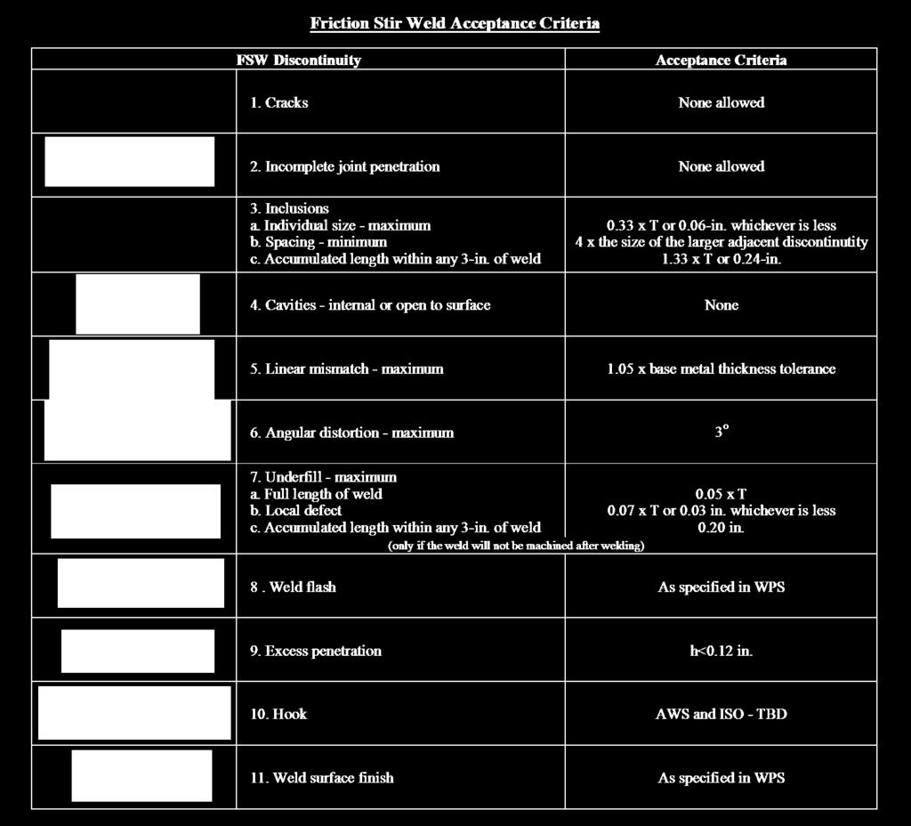
13 TABLE 3 FIGURE 4 - Hook 12
14 8) Weld classifications None of the existing FSW process standards address ballistic welding. However the three existing FSW process standards each designate separate weld quality criteria for several levels of classification dependent on the end use of the weldment. See Table 4. IMPORTANT FINDINGS AND CONCLUSIONS A) Specific FSW welding joint design characteristics for ballistic structures, which would be similar to those shown in MIL-HDBK-21, have not been developed. B) FSW has not been evaluated on most of the approved ballistic armor materials and relevant thickness ranges. See Appendix D. IMPLICATIONS FOR FURTHER RESEARCH A) An equivalent FSW joint for each of the approved fusion weld ballistic joints should be defined. See Appendix B. B) For each ballistic FSW weld joint, the relationships of each joint s dimensional parameters and their effect on weld strength should be studied and optimized. C) The developed FSW weld joints should be qualified for ballistic application by undergoing ballistic shock testing. D) For each of the approved ballistic armor materials, the strength and metallurgy of FSW joints should be studied to confirm the applicable of FSW to the respective materials. Because of its solid-state nature, the FSW process may be feasible for joining materials that are known to be difficult or impossible to weld by fusion methods. 13
15 SIGNIFICANT HARDWARE DEVELOPMENT Not applicable SPECIAL COMMENTS None 14

16 APPENDIX A FSW Definitions (The contents of this appendix are taken from Section 3 of the preliminary FSW standard that has been prepared by Focus: HOPE Center for Advanced Technology.) 3.1 Advancing side of weld. The side of the weld where the direction of tool rotation is the same as the direction of welding. See Figure Angular distortion of the joint. A distortion between two welded pieces such that their surface planes are not parallel or at the intended angle. See Figure 3.2. FIGURE Angular Distortion of the Joint 3.3 Anvil. The structure supporting the root side of the joint. 3.4 Axial force. Force applied to the work piece along the axis of tool rotation. See Figure Bobbin tool. A FSW tool with two shoulders separated by a fixed length or an adjustable length pin. See Figure 3.3. Note - The self-reacting bobbin tool allows the shoulders to automatically maintain contact with the workpiece. 15


17 FIGURE Bobbin Tool 3.6 Cavity. A void-type discontinuity within a solid-state weld. See Figure 3.4. FIGURE Cavity 3.7 Complex weld joint. A continuous weld joint with variations in section thickness and/or tapered thickness transitioning. 3.8 Direction of tool rotation. The rotation as viewed from the spindle that is rotating the tool. See Figure Dwell time at end of weld. The time interval after travel has stopped but before the rotating tool has begun to withdraw from the weld Dwell time at start of weld. The time interval between when the rotating tool reaches its maximum depth in the parent material and the start of travel Engineering Authority. The contracting agency or corporate organization that acts for and in behalf of the Customer on all matters within the scope of this standard. The Engineering Authority has the responsibility for the structural integrity or maintenance of airworthiness of the hardware and compliance with all contract documents Engineering drawing. Technical information, given on an information carrier, presented graphically in accordance with agreed rules and usually to scale Entrance block. A sacrificial piece of metal that is secured to the beginning of a FSW joint, and provides filler material as the tool enters the edge of a workpiece. 16

18 3.14 Exit hole. The depression located at the weld termination point which remains after the withdrawal of the tool. See Figure Exit block. A sacrificial piece of metal that is secured to the end of a FSW joint, and by providing filler material, eliminates an exit hole in the weldment. The exit hole will be relocated to the exit block Contractor. A person or organization that is responsible for production welding Faying surface. The surface of one component which is intended to be in contact with, or in close proximity to the surface of another component to form a joint Fixed pin. A fixed length pin protruding from the shoulder and the pin's rotation is the same as the shoulder during welding Flash. Material expelled along the weld toe during FSW. See Figure 3.5. FIGURE Toe Flash 3.20 Force control. A method to maintain the required force on the tool during welding Friction stir welding. A material joining process where two or more metal workpieces are joined by the friction heating and mixing of material in the plastic state caused by a rotating tool that traverses along the weld. See Figures 3.1 and 3.6. FIGURE 3.6 Graph of FSW Process 17

.")

19 3.22 Friction stir welding methods. Methods include, but are not limited to, robotic, single spindle, multiple spindles, self-reacting tool, and simultaneous two-sided welding Friction stir welding operator. A person who performs fully mechanized or automatic friction stir welding Heat affected zone (HAZ). The area of weld joint which has had its microstructure and properties altered by the heat of a welding process Heel. Part of the tool shoulder that is at the rear of the tool relative to its forward motion. See Figure Heel plunge depth. Distance the heel extends into the workpiece. See Figure 3.7. FIGURE 3.7 Heel Plunge Depth 3.27 Hook. Faying surface that curves upward or downward along the side of the weld metal in a friction stir welded lap joint. See Figure 3.8. FIGURE 3.8 Hook in a Lap Weld 18


20 3.28 Hole plug. A piece of filler metal which has been machined to allow its insertion into a hole and will be joined to the structure by FSW Incomplete joint penetration. A weld discontinuity where the full thickness of the joint has not been welded. See Figure 3.9. FIGURE 3.9 Incomplete Joint Penetration 3.30 Lateral offset. The distance from the tool axis to the faying surface. See Figure FIGURE 3.10 Lateral Offset 19
21 3.31 Linear mismatch across joint. Misalignment between two welded pieces such that while their surface planes are parallel, they are not in the required plane. See Figure FIGURE Figure Linear Mismatch 3.32 Multi-run welding. Welding in which the weld is made in more than one run Multiple spindles. A friction stir welding system with two or more spindles Pin. Part of the welding tool that extends into the workpiece to make the weld. See Figure NOTE: The pin can be either fixed or adjustable Pipe. Tube in standardized combination of outside diameter and wall thickness. NOTE: In this standard, the term pipe will be used for pipe and tube Plasticity.The softening of metal material before it reaches its melting point. The mechanism usually becomes dominant at temperatures greater than approximately one third of the absolute melting temperature Plate. Rolled, extruded, cast, forged, or deposited products other than pipe in thickness greater than inches [0.152 mm]. NOTE: In this standard, the term plate is being used to describe all metal products, other than pipe Position control. A method to maintain the required position of the tool during welding Preliminary Welding Procedure Specification (pwps). A document containing the required variables of a qualified welding procedure Pre-production test. A Welding test having the same function as a welding procedure test, but based on a non-standard test piece representative of the production conditions Procedure qualification variable. Controllable detail, which, if changed beyond the limitations of the welding procedure specification, requires re-qualification of the WPS Production sample test. Testing of actual welded products sampled from a continuous production Referencing Document. A fabrication code, specification, contract document, or internal document, such as the engineering drawing, quality control or quality assurance manuals that invokes this specification Retreating side of weld. Side of the weld where the direction of tool rotation is opposite to the welding direction. See Figure Self-reacting tool. A tool with two shoulders separated by a fixed length probe or an adjustable-length probe. Also see 3.5, Bobbin Tool. 20
22 3.46 Shoulder. The portion of the tool contacting the surface of the parent material during welding. See Figure Side tilt angle. The angle between the tool's axis and an axis normal to the base material surface, measured in a plane perpendicular to the weld path Single run welding. Welding in which the weld is made in one run Single spindle. A friction stir welding system with one spindle Standard welding test. Welding and testing of a standardized test piece in order to qualify a welding operator Stirred zone. The oval shaped region in the center of the weld, where a fine-grained, equated microstructure exists Test piece. A weldment used for testing purposes Test specimen. Portion cut from a test piece in order to perform a specified destructive test Test specimen blank. Portion of a test piece removed for the production of a destructive test specimen. NOTE: In some cases, the test specimen blank is also the test specimen Thermo-mechanically affected zone (TMAZ). The area of weld joint that has been plastically deformed by the tool and has also had its microstructure and properties altered by the heat of a welding process Tilt angle. The angle between the tool's axis and a plane perpendicular to the weld path, when viewed perpendicular to the weld path Tool (friction stir welding). A FSW tool is the rotating component that includes the shoulder and pin. See Figure Generally, as base material thickness is increased, the shoulder diameter and pin length are also increased. Various pin designs include, but are not limited to, threaded, scrolled, fluted, or smooth. Pins may also have adjustable length and, with a special spindle, counter-rotating. NOTE- A tool usually has a shoulder and a pin, but a tool may have more than one shoulder or more than one pin. Also, a tool may not have a shoulder or a pin. FIGURE FSW Tool 21
23 3.58 Tool rotation speed. Angular speed of the welding tool in revolutions per minute Travel speed. Rate at which the welding operation progresses in the direction of welding Tube. Hollow, wrought product that is long in relation to its cross section, which is symmetrical and is round, elliptical, a regular hexagon or octagon, or square or rectangular with sharp or rounded corners, and has uniform wall thickness except as affected by corner radii Underfill. A depression resulting when the weld face is below the adjacent parent material surface. See Figure NOTE - This is a common characteristic of the friction stir welding process. FIGURE Underfill 3.62 Weld overlap area (WOA). The area where the end of the weld overlaps the start of the weld. NOTE - A WOA is common during pipe welding Welding Procedure Specification (WPS). A document that has been qualified and provides the required variables of the welding procedure to ensure repeatability during production welding Welding Procedure Qualification Record (WPQR). The WPQR is a statement of the test results of each test specimen. 22
24 APPENDIX B Design Characteristics of Ballistic Weld Joints FSW vs. Fusion Welding 23
25 APPENDIX B Fusion weld joint (MIL-HDBK-21) Equivalent FSW joint (AWS or ISO) Type I Single V-Grooved Butt Joint 24
26 APPENDIX B Fusion weld joint (MIL-HDBK-21) Equivalent FSW joint (AWS or ISO) Type 2 Single V-Grooved Butt Joint with Backing 25
27 APPENDIX B Fusion weld joint (MIL-HDBK-21) Equivalent FSW joint (AWS or ISO) Type 3 Double V-Grooved Butt Joint 26
")
 Types 4 & 6 Corner")
28 APPENDIX B Fusion weld joint (MIL-HDBK-21) Equivalent FSW joint (AWS or ISO) Types 4 & 6 Corner Joints 27
")
 Types 5 & 7")
29 APPENDIX B Fusion weld joint (MIL-HDBK-21) Equivalent FSW joint (AWS or ISO) Types 5 & 7 T Joints 28
30 APPENDIX B ` Fusion weld joint (MIL-HDBK-21) Equivalent FSW joint (AWS or ISO) Type 10 Joints with Mechanical Reinforcement 29
31 APPENDIX C FSW Test Weld Geometry (From AWS D17.3) 30

32 APPENDIX D Ballistic Armor Materials MIL-SPECS L-DTL L-DTL L-DTL MIL-A-11356F MIL-DTL-12560J MIL-DTL-46177C Control-rolled 9 L-DTL MIL-PRF C D referenced in current US Army armor welding codes D NOT referenced!lli@j Unfeasible thickness ranges 31
Using SolidWorks & CFD to Create The Next Generation Airlocks
 Using SolidWorks & CFD to Create The Next Generation Airlocks Matthew Gaffney Mechanical Engineer Geo-Centers, INC US Army Natick Soldier Center Natick, MA 01760 508-233-5557 Matthew.gaffney@natick.army.mil
AFRL-RX-WP-TP
 AFRL-RX-WP-TP-2012-0215 REVERSE PRESSURE CAPABLE FINGER SEAL (PREPRINT) Nathan Gibson and Joe Yanof Honeywell International, Inc. JANUARY 2012. See additional restrictions described on inside pages STINFO
AFRL-RH-WP-TR
 AFRL-RH-WP-TR-2016-0040 C-130J BREATHING RESISTANCE STUDY George W. Miller Air Force Research Laboratory Wright-Patterson Air Force Base, OH 45433 May 2016 Final Report STINFO COPY AIR FORCE RESEARCH LABORATORY
Kelly Legault, Ph.D., P.E. USACE SAJ
 Kelly Legault, Ph.D., P.E. USACE SAJ Report Documentation Page Form Approved OMB No. 0704-0188 Public reporting burden for the collection of information is estimated to average 1 hour per response, including
Development of Low Volume Shape Memory Alloy Variable Ballast System for AUV Use
 Development of Low Volume Shape Memory Alloy Variable Ballast System for AUV Use Dr. Graeme J Rae Ocean Engineering Program Division of Marine and Environmental Systems Florida Institute of Technology
M2.50-cal. Multishot Capabilities at the US Army Research Laboratory
 ARL-TN-0694 SEP 2015 US Army Research Laboratory M2.50-cal. Multishot Capabilities at the US Army Research Laboratory by Todd Brinkman Approved for public release; distribution is unlimited. NOTICES Disclaimers
Future Trends Internet of Things, Automated Welding and Additive Manufacturing in India. Friction Stir Welding
 Future Trends Internet of Things, Automated Welding and Additive Manufacturing in India Friction Stir Welding Friction Stir Welding in Action Take-up of FSW by Industry 300 280 260 240 220 200 180 160
Navy Shipbuilding Industrial Base
 Navy Shipbuilding Industrial Base May 11, 2011 David J. Berteau Senior Adviser and Director, Defense-Industrial Initiatives Report Documentation Page Form Approved OMB No. 0704-0188 Public reporting burden
COST COMPARISON OF FSW AND MIG WELDED ALUMINIUM PANELS
 COST COMPARISON OF FSW AND MIG WELDED ALUMINIUM PANELS Jukka Mononen 1 Mika Sirén 2 Hannu Hänninen 1 jukka.t.mononen@hut.fi mika.siren@vtt.fi hannu.hanninen@hut.fi 1) Helsinki University of Technology
OPENINGS AND REINFORCEMENTS 26
 ASME BPVC.VIII.1-2015 UG-35.2 UG-36 (4) It is recognized that it is impractical to write requirements to cover the multiplicity of devices used for quick access, or to prevent negligent operation or the
DEVELOPMENT OF PRIMARY FRAGMENTATION SEPARATION DISTANCES FOR CASED CYLINDRICAL MUNITIONS
 DEVELOPMENT OF PRIMARY FRAGMENTATION SEPARATION DISTANCES FOR CASED CYLINDRICAL MUNITIONS by William H. Zehrt, Jr., P. E. and Michelle M. Crull, PhD, P. E. U. S. Army Engineering and Support Center, Huntsville
SEMFWE305 HY20 04 Welding materials by the Semi-Automatic MIG/MAG and Flux Cored Arc processes
 SEMFWE305 HY20 04 Welding materials by the Semi-Automatic MIG/MAG and Flux Cored Overview This standard identifies the competencies you need to prepare and operate semi-automatic MIG, MAG and flux cored
ADVANCES IN NDT TECHNIQUES FOR FRICTION STIR WELDING JOINTS OF AA2024
 ADVANCES IN NDT TECHNIQUES FOR FRICTION STIR WELDING JOINTS OF AA2024 Telmo Santos, Pedro Vilaça, Luís Reis, Luísa Quintino, Manuel de Freitas Technical University of Lisbon, Instituto Superior Técnico,
Internal Waves and Mixing in the Aegean Sea
 Internal Waves and Mixing in the Aegean Sea Michael C. Gregg Applied Physics Laboratory, University of Washington 1013 NE 40 th St. Seattle, WA 98105-6698 phone: (206) 543-1353 fax: (206) 543-6785 email:
AN EXPERIMENTAL INVESTIGATION OF SPILLING BREAKERS
 AN EXPERIMENTAL INVESTIGATION OF SPILLING BREAKERS Prof. James H. Duncan Department of Mechanical Engineering University of Maryland College Park, Maryland 20742-3035 phone: (301) 405-5260, fax: (301)
z Interim Report for May 2004 to October 2005 Aircrew Performance and Protection Branch Wright-Patterson AFB, OH AFRL-HE-WP-TP
 AFRL-HE-WP-TP-26-89 Neck Muscle Fatigue with Helmet-Mounted Systems Edward S. Eveland Joseph A. Pellettiere Air Force Research Laboratory LL September 26 z Interim Report for May 24 to October 25 (n 261124
OE Barricade Guide Development. Michelle Crull, PhD, PE Wallace Watanabe James Manthey, PE Charles Barker, PE
 OE Barricade Guide Development by Michelle Crull, PhD, PE Wallace Watanabe James Manthey, PE Charles Barker, PE U.S. Army Engineering and Support Center, Huntsville ATTN: CEHNC-ED-CS-S P.O. Box 1600 Huntsville,
High-Frequency Scattering from the Sea Surface and Multiple Scattering from Bubbles
 High-Frequency Scattering from the Sea Surface and Multiple Scattering from Bubbles Peter H. Dahl Applied Physics Laboratory College of Ocean and Fisheries Sciences University of Washington Seattle, Washington
Evaluation of Friction Stir Weld Process and Properties for Aircraft Application
 Evaluation of Friction Stir Weld Process and Properties for Aircraft Application Christian Widener Evaluation of Friction Stir Weld Process and Properties for Aircraft Application Motivation and Key Issues
Air-Sea Interaction Spar Buoy Systems
 DISTRIBUTION STATEMENT A: Distribution approved for public release; distribution is unlimited Air-Sea Interaction Spar Buoy Systems Hans C. Graber CSTARS - University of Miami 11811 SW 168 th Street, Miami,
Long-Term Autonomous Measurement of Ocean Dissipation with EPS-MAPPER
 Long-Term Autonomous Measurement of Ocean Dissipation with EPS-MAPPER Neil S. Oakey Bedford Institute of Oceanography Dartmouth, Nova Scotia Canada B2Y 4A2 phone: (902) 426-3147 fax: (902) 426-7827 e-mail:
Characterizing The Surf Zone With Ambient Noise Measurements
 Characterizing The Surf Zone With Ambient Noise Measurements LONG-TERM GOAL Grant Deane Marine Physical Laboratory Scripps Institution of Oceanography La Jolla, CA 93093-0213 phone: (619) 534-0536 fax:
Aircraft Fuel Cell Repair Equipment
 Aircraft Fuel Cell Repair Equipment After Iniative Report AMB-05-005 PROJECT MANAGER: Capt John M. Yerger DSN 650-7608 john.yerger@mcguire.af.mil Air Force Air Mobility Battlelab DISTRIBUTION A. Approved
Other Si min/max. Cr min/max. 0.4/ / / / Bal.
 178.46 Specification 3AL seamless aluminum cylinders. (a) Size and service pressure. A DOT 3AL cylinder is a seamless aluminum cylinder with a imum water capacity of 1000 pounds and minimum service pressure
High Frequency Acoustical Propagation and Scattering in Coastal Waters
 High Frequency Acoustical Propagation and Scattering in Coastal Waters David M. Farmer Graduate School of Oceanography (educational) University of Rhode Island Narragansett, RI 02882 Phone: (401) 874-6222
MIL-STD-883H METHOD EXTERNAL VISUAL
 * EXTERNAL VISUAL 1. PURPOSE. The purpose of this test method is to verify the workmanship of hermetically packaged devices. This test method shall also be utilized to inspect for damage due to handling,
TITLE: Assessing the Hydrodynamic Performance of Fouling-Release Surfaces (ONR Research Contract # N WR )
") TITLE: Assessing the Hydrodynamic Performance of Fouling-Release Surfaces (ONR Research Contract # N00014-07-WR-2-0213) INVESTIGATOR: Associate Professor Michael P. Schultz, Naval Architecture & Ocean
TITLE: Assessing the Hydrodynamic Performance of Fouling-Release Surfaces (ONR Research Contract # N00014-07-WR-2-0213) INVESTIGATOR: Associate Professor Michael P. Schultz, Naval Architecture & Ocean
( max)o Wind Waves 10 Short Swell (large wave steepness) 25 Long Swell (small wave steepness) 75
o Wind Waves 10 Short Swell (large wave steepness) 25 Long Swell (small wave steepness) 75") CEPi-I-18 REvKn, 3188 IRREGULAR WAVE DIFFRACTION BY GODA'S KETHOD PURPOSE : To provide a simplified method for determining random wave diffraction coefficients for a semi-infinite breakwater. GENERAL :
CEPi-I-18 REvKn, 3188 IRREGULAR WAVE DIFFRACTION BY GODA'S KETHOD PURPOSE : To provide a simplified method for determining random wave diffraction coefficients for a semi-infinite breakwater. GENERAL :
Preparing and using manual gas welding equipment
 Unit 030 Preparing and using manual gas welding Level: 2 Credit value: 14 NDAQ number: 500/9514/6 Unit aim This unit covers the skills and knowledge needed to prove the competences required to cover a
BRRAKING WAVE FORCES ON WALLS
 CETN-III-38 3/88 BRRAKING WAVE FORCES ON WALLS PURPOSE: To introduce the Goda method as an alternative to the Minikin method for the determination of breaking wave forces on semirigid wall structures.
AWS New Welding Technologies
 AWS New Welding Technologies Friction Stir Welding - Recent Developments and Process Enhancements Presentation Contents: FSW Market Review Challenges for FSW Users Process Enhancements Summary Mike Russell
Marine Mammal Acoustic Tracking from Adapting HARP Technologies
 DISTRIBUTION STATEMENT A: Approved for public release; distribution is unlimited. Marine Mammal Acoustic Tracking from Adapting HARP Technologies Sean M. Wiggins and John A. Hildebrand Marine Physical
SECTION 48 - TRAFFIC STRIPES AND PAVEMENT MARKINGS TABLE OF CONTENTS
 SECTION 48 - TRAFFIC STRIPES AND PAVEMENT MARKINGS TABLE OF CONTENTS Section Page 48-1 GENERAL...48.1 48-2 THERMOPLASTIC TRAFFIC STRIPES AND PAVEMENT MARKINGS...48.1 48-3 PAINTED TRAFFIC STRIPES AND PAVEMENT
REPORT DOCUMENTATION PAGE
 REPORT DOCUMENTATION PAGE Form Approved OMB NO. 0704-0188 The public reporting burden for this collection of information is estimated to average 1 hour per response, including the time for reviewing instructions,
Temporary Flying Restrictions Due to Exogenous Factors
 Army Regulation 40 8 Medical Services Temporary Flying Restrictions Due to Exogenous Factors Headquarters Department of the Army Washington, DC 17 August 1976 UNCLASSIFIED REPORT DOCUMENTATION PAGE Form
DVS Technical Codes an Bulletins
 DVS Technical Codes an Bulletins DVS 1904-1 (2010-02) Adhesive bonding of plastics in domestic installation Requirements on plants and personnel... 1 DVS 1904-2 (2010-02) Adhesive bonding of plastics in
Imaging the Lung Under Pressure
 DISTRIBUTION STATEMENT A: Approved for public release; distribution is unlimited. Imaging the Lung Under Pressure Peter L. Tyack, Andreas Fahlman, Michael Moore, and Darlene Ketten Woods Hole Oceanographic
User Instruction Manual Fixed Beam Anchor
 Instructions for the following series products: FIXED BEAM ANCHOR Model Numbers: The Ultimate in Fall Protection 2108406 2108407 2108408 2108409 2108410 2108411 User Instruction Manual Fixed Beam Anchor
P-04 Stainless Steel Corrugated Hoses and Metal Bellows Expansion Joints
 Guideline No.P-04 (201510) P-04 Stainless Steel Corrugated Hoses and Metal Bellows Expansion Joints Issued date: 20 th October 2015 China Classification Society Foreword This Guideline is a part of CCS
Waves, Turbulence and Boundary Layers
 Waves, Turbulence and Boundary Layers George L. Mellor Program in Atmospheric and Oceanic Sciences Princeton University Princeton NJ 8544-71 phone: (69) 258-657 fax: (69) 258-285 email: glm@splash.princeton.edu
The Need for a New Joining Technology for the Closure Welding of Radioactive Materials Containers
 ABSTRACT The Need for a New Joining Technology for the Closure Welding of Radioactive Materials Containers - 9516 G.R. Cannell Fluor Government Group P.O Box 1000, Richland, WA 99352 G.J. Grant Pacific
New Highly Productive Phased Array Ultrasonic Testing Machine for Aluminium Plates for Aircraft Applications
 19 th World Conference on Non-Destructive Testing 2016 New Highly Productive Phased Array Ultrasonic Testing Machine for Aluminium Plates for Aircraft Applications Christoph HENKEL 1, Markus SPERL 1, Walter
Calculation of the Internal Blast Pressures for Tunnel Magazine Tests
 Calculation of the Internal Blast Pressures for Tunnel Magazine Tests by Kevin Hager Naval Facilities Engineering Service Center Pt Hueneme, CA and Naury Birnbaum Century Dynamics, Inc. San Ramon, CA ABSTRACT
The Influence of Process Parameters on the Temperature Profile of Friction Stir Welded Aluminium Alloy 6063-T6 Pipe Butt Joint
 From the SelectedWorks of Azman Ismail Summer June 7, 2015 The Influence of Process Parameters on the Temperature Profile of Friction Stir Welded Aluminium Alloy 6063-T6 Pipe Butt Joint Azman Ismail Mokhtar
Stability & Control Aspects of UCAV Configurations
 Stability & Control Aspects of UCAV Configurations Paul Flux Senior Aerodynamicist BAE SYSTEMS Air Programmes Report Documentation Page Form Approved OMB No. 0704-0188 Public reporting burden for the collection
Compact Triple Cabinet Outlet Station Model Installation and Operating Instructions
 Compact Triple Cabinet Outlet Station Model 6258-1 Installation and Operating Instructions The Porter Compact Triple Outlet Station (6258-1) provides a quick, safe, and reliable method of connection to
Compact Triple Cabinet Outlet Station Model B Installation and Operating Instructions
 PORTER Parker Hannifin Corporation Porter Instrument Division 245 Township Line Rd. P.O. Box 907 Hatfield, PA 19440-0907 USA (215) 723-4000 / fax (215) 723-5106 Compact Triple Cabinet Outlet Station Model
Pressure Equipment Directive PED 2014/68/EU Commission's Working Group "Pressure"
 F. INTERPRETATION OF THE ESSENTIAL SAFETY REQUIREMENTS ON MANUFACTURING Guideline F-01 Guideline related to: Annex 1 Section 3.1.2 According to section 3.1.2 (permanent joining) of Annex I, the third party
DoD Coral Reef Protection and Management Program
 DoD Coral Reef Protection and Management Program PROJECT TEAM U.S. NAVY TOM EGELAND (ASN(I&E)) LORRI SCHWARTZ (NAVFAC) ALEX VIANA (NFESC) STEVE SMITH (NFESC) BOSTON UNIV. MARINE PRG. PHILLIP LOBEL MINDY
GENERAL GUIDELINES FOR PROPER RIGGING PRACTICES AND INSPECTION & REMOVAL CRITERIA FOR SLINGS PER OSHA
 GENERAL GUIDELINES FOR PROPER RIGGING PRACTICES AND INSPECTION & REMOVAL CRITERIA FOR SLINGS PER OSHA 1910.184 SAFE OPERATING PRACTICES -.Whenever any sling is used, the following practices shall be observed:
Operations and Instruction Manual Might Swivel Model # Concrete and Steel Anchorage Connector ANSI Z ,000 lbs / 44kn
 Operations and Instruction Manual Might Swivel Model # 00238 Concrete and Steel Anchorage Connector ANSI Z359.1 10,000 lbs / 44kn Description: Zinc plated forged heat treated steel, Special design gives
SECTION 48 - TRAFFIC STRIPES AND PAVEMENT MARKINGS TABLE OF CONTENTS
 SECTION 48 - TRAFFIC STRIPES AND PAVEMENT MARKINGS TABLE OF CONTENTS Section Page 48-1 GENERAL... 48.1 48-2 THERMOPLASTIC TRAFFIC STRIPES AND PAVEMENT MARKINGS... 48.1 48-3 PAINTED TRAFFIC STRIPES AND
User Instruction Manual Fixed Beam Anchor
 User Instruction Manual Fixed Beam Anchor This manual is intended to meet the Manufacturer s Instructions as required by ANSI Z359.1 and ANSI A10.14, and should be used as part of an employee training
Examples of Carter Corrected DBDB-V Applied to Acoustic Propagation Modeling
 Naval Research Laboratory Stennis Space Center, MS 39529-5004 NRL/MR/7182--08-9100 Examples of Carter Corrected DBDB-V Applied to Acoustic Propagation Modeling J. Paquin Fabre Acoustic Simulation, Measurements,
FRACTURE TOUGHNESS OF FRICTION STIR WELDED ALUMINIUM ALLOY
 FRACTURE TOUGHNESS OF FRICTION STIR WELDED ALUMINIUM ALLOY W. M. Syafiq 1, M. A. Rojan 1, M. S. Abdul Majid 1 and N. A. Jaafar 2 1 School of Mechatronics, Kampus Pauh Putra, Universiti Malaysia Perlis,
LIGHTBLANK Reducing the Weight of Al BIW by using Friction Stir Tailor Welded Blanks Pressed by HFQ
 LIGHTBLANK Reducing the Weight of Al BIW by using Friction Stir Tailor Welded Blanks Pressed by HFQ Joao Gandra joao.gandra@twi.co.uk friction@twi.co.uk 1 Overview Transport sector demands How can FSW
Evaluating the Design Safety of Highway Structural Supports
 Evaluating the Design Safety of Highway Structural Supports by Fouad H. Fouad and Elizabeth A. Calvert Department of Civil and Environmental Engineering The University of Alabama at Birmingham Birmingham,
IAPMO GUIDE CRITERIA FOR BALL VALVES IAPMO IGC PURPOSE
 INTERNATIONAL ASSOCIATION OF PLUMBING AND MECHANICAL OFFICIALS IAPMO GUIDE CRITERIA FOR BALL VALVES IAPMO IGC 157-20067 1 PURPOSE 1.1 The purpose of this standard is to establish an acceptable standard
Press Release. Friction Stir Welding: Grenzebach extends its portfolio
 Friction Stir Welding: Grenzebach extends its portfolio Higher dynamics, higher welding speeds, lower process forces and even higher quality welding seams and welding surfaces: at the Düsseldorf Schweissen
THE EFFECTS OF ULTRAHIGH-PRESSURE WATERJET IMPACT ON HIGH EXPLOSIVES
 THE EFFECTS OF ULTRAHIGH-PRESSURE WATERJET IMPACT ON HIGH EXPLOSIVES Paul L. Miller Senior Principal Developmental Engineer Alliant Techsystems 5901 Lincoln Drive Edina, MN 55436 ABSTRACT Alliant Techsystems
Revisions to the Regulations for Agility Trials
 Revisions to the Regulations for Agility Trials Effective January 2, 2018 Equipment changes may be done prior to January 2, 2018, but must be completed by January 2, 2018 This insert is issued as a supplement
This is an author-deposited version published in: Handle ID:.http://hdl.handle.net/10985/8774
 Science Arts & Métiers (SAM) is an open access repository that collects the work of Arts et Métiers ParisTech researchers and makes it freely available over the web where possible. This is an author-deposited
Mild steel. Stainless steel. HPR130XD Auto Gas Revision 2. Nozzle retaining cap. tube. Shield cap 30 A 50 A 80 A 130 A
 Operation Mild steel cap Nozzle retaining cap Nozzle Swirl ring Electrode 220194 220754 220193 220180 220192 220555 220754 220554 220553 220552 Water tube 30 A 50 A 220340 220747 80 A 220189 220756 220188
STANDARD SPECIFICATION FOR SPLIT TEES (HOT TAP MATERIAL)
") STANDARD SPECIFICATION FOR SPLIT TEES (HOT TAP MATERIAL) TEE (HOT TAPPING MATERIAL) S-04-02-040 Page 1 of 7 1.0 SCOPE This specification covers the basic requirements for the design, manufacture and supply
STANDARD SPECIFICATION FOR SPLIT TEES (HOT TAP MATERIAL) TEE (HOT TAPPING MATERIAL) S-04-02-040 Page 1 of 7 1.0 SCOPE This specification covers the basic requirements for the design, manufacture and supply
Driveway Design Criteria
 Design Manual Chapter 5 - Roadway Design 5L - Access Management 5L-4 Driveway Design Criteria A. General For efficient and safe operations, access drives and minor public street intersections can be improved
PUSH PIER SYSTEMS STABILITY. SECURITY. INTEGRITY. Push Pier Systems PN #MBPPT
 PUSH PIER SYSTEMS STABILITY. SECURITY. INTEGRITY. PN #MBPPT Push Pier Systems About Foundation Supportworks is a network of the most experienced and knowledgeable foundation repair and new construction
PRODUCT SPECIFICATION. SFP+ Cage and Cage Assembly 1 of 8 A
 SFP+ Cage and Cage Assembly 1 of 8 A 1.0 Objective This specification defines the performance, test, quality and reliability requirements of the _Small Form-factor Pluggage (SFP+) product. 2.0 Scope This
DISTRIBUTION: Electronic Recipients List TRANSMITTAL LETTER NO. (13-01) MINNESOTA DEPARTMENT OF TRANSPORTATION. MANUAL: Road Design English Manual
 MINNESOTA DEPARTMENT OF TRANSPORTATION. MANUAL: Road Design English Manual") DISTRIBUTION: Electronic Recipients List MINNESOTA DEPARTMENT OF TRANSPORTATION DEVELOPED BY: Design Standards Unit ISSUED BY: Office of Project Management and Technical Support TRANSMITTAL LETTER NO.
DISTRIBUTION: Electronic Recipients List MINNESOTA DEPARTMENT OF TRANSPORTATION DEVELOPED BY: Design Standards Unit ISSUED BY: Office of Project Management and Technical Support TRANSMITTAL LETTER NO.
MIL-DTL-5886G Ballistic Fragmentation Qualification of the Carleton Life Support Systems Oxygen Cylinder, Part Number
 MIL-DTL-5886G Ballistic Fragmentation Qualification of the Carleton Life Support Systems Oxygen Cylinder, Part Number 3270081-0201 by Brian G. Smith ARL-TR-3759 March 2006 Approved for public release;
Engineering Data Sheet
 Page 1 of 6 CE MARKING AND THE PRESSURE EQUIPMENT DIRECTIVE 97/23/EC Valves must be installed into a well designed system and it is recommended that the system be inspected in accordance with the appropriate
SECTION BUTTERFLY VALVES
 SECTION 15112 BUTTERFLY VALVES PART 1 GENERAL 1.01 SUMMARY A. All butterfly valves shall be of the tight closing, rubber seated type and fully comply with the latest revision of AWWA Standard C504, Class
Installing, Repairing or Modifying Construction Resources by Heating, Welding, Brazing, Soldering and Thermal Cutting in the Workplace L/505/0144
 Unit Title Ofqual unit reference number (code) Organisation Reference QCF 665 Unit Level Unit Sub Level Installing, Repairing or Modifying Construction Resources by Heating, Welding, Brazing, Soldering
TABLE OF CONTENTS International Racquetball Federation officially approved specifications. Copyright 01/13/1983; rev.
 Racquetball Court Specifications TABLE OF CONTENTS International Racquetball Federation officially approved specifications. Copyright 01/13/1983; rev. 1988; 1997, 2013 SECTION ONE: Performance and Specifications
Use of Underwater Dry Welding for In Situ Repair to Offshore Structures. Sabine Powell 02/12/2016
 Use of Underwater Dry Welding for In Situ Repair to Offshore Structures Sabine Powell engineering@neptunems.com 02/12/2016 In Situ Welding Steel Structures Suitability of Repair Methods Mobile Offshore
SEMFEW205 - SQA Unit Code H1VP 04 Joining materials by the manual MIG/MAG and other continuous wire processes
 Joining materials by the manual MIG/MAG and other continuous wire Overview This unit identifies the competencies you need to prepare and operate manual MIG, MAG or cored-wire arc welding equipment, in
User Instructions 1789 Parapet Wall Anchor
 User Instructions 1789 Parapet Wall Anchor This manual is intended to meet the Manufacturer Instructions as required by ANSI Z359.1 and should be used as part of an employee training program as required
Behavioral Response of Dolphins to Signals Simulating Mid-Frequency Sonar
 DISTRIBUTION STATEMENT A. Approved for public release; distribution is unlimited. Behavioral Response of Dolphins to Signals Simulating Mid-Frequency Sonar Dorian S. Houser Biomimetica, 7951 Shantung Drive,
County of Sacramento Standard Construction Specifications January 1, 2008 TECHNICAL PROVISIONS
 County of Sacramento Standard Construction Specifications January 1, 2008 TECHNICAL PROVISIONS SECTION 48 TRAFFIC STRIPES AND PAVEMENT MARKINGS 48-1 GENERAL Traffic stripes and pavement markings shall
The evolution of the Ex-proof flame path
 April 2017 The evolution of the Ex-proof flame path As written in previous dissertation, the most critical part of a flameproof enclosure 'Ex d' is the flame path. Although the Standards are divided into
TECHNICAL MANUAL. COPRA Anchoring Coupler. For Smart Bolted Connections
 TECHNICAL MANUAL Anchoring Coupler For Smart Bolted Connections Version: PEIKKO GROUP 03/2017 Anchoring Coupler For bolted connections Multi-purpose anchoring system for all bolted connections Simplifi
SEMFWE SQA Unit Code H1W9 04 Forming platework using power rolling machines
 Overview This standard identifies the competencies you need to bend and form plate for fabrications in accordance with approved procedures using power operated pinch or pyramid rolls which may be hand
DOMESTIC PREPAREDNESS: PROTECTION FACTOR TESTING OF THE SE-SHIELD SUIT WITH THE SE400 POWERED AIR PURIFYING RESPIRATOR (PAPR)
") ECBC-TR- XXXX DOMESTIC PREPAREDNESS: PROTECTION FACTOR TESTING OF THE SE-SHIELD SUIT WITH THE SE400 POWERED AIR PURIFYING RESPIRATOR (PAPR) Adam D. Seiple Alex G. Pappas ENGINEERING DIRECTORATE April 2003
ECBC-TR- XXXX DOMESTIC PREPAREDNESS: PROTECTION FACTOR TESTING OF THE SE-SHIELD SUIT WITH THE SE400 POWERED AIR PURIFYING RESPIRATOR (PAPR) Adam D. Seiple Alex G. Pappas ENGINEERING DIRECTORATE April 2003
THE PROCESS OF JOINT INTEGRITY
 BOLTED JOINTS A.333 THE PROCESS OF JOINT INTEGRITY To assist in managing a process, ask yourself the following questions: why, what, who, and how? Why do we need a Flange Joint Integrity program? This
ZIN Technologies PHi Engineering Support. PHi-RPT CFD Analysis of Large Bubble Mixing. June 26, 2006
 ZIN Technologies PHi Engineering Support PHi-RPT-0002 CFD Analysis of Large Bubble Mixing Proprietary ZIN Technologies, Inc. For nearly five decades, ZIN Technologies has provided integrated products and
WARNING! DO NOT THROW AWAY THESE INSTRUCTIONS! READ AND UNDERSTAND BEFORE USING EQUIPMENT!
 Guardian Fall Protection Kent, WA 800-466-6385 www.guardianfall.com GENERAL SYSTEM SELECTION CRITERIA: Selection of fall protection shall be made by a Competent Person. All fall protection equipment shall
Remote Monitoring of Dolphins and Whales in the High Naval Activity Areas in Hawaiian Waters
 DISTRIBUTION STATEMENT A: Approved for public release; distribution is unlimited. Remote Monitoring of Dolphins and Whales in the High Naval Activity Areas in Hawaiian Waters Whitlow W. L. Au and Marc
TRAFFIC CONTROL DEVICES
 TRAFFIC CONTROL DEVICES SIGNS Temporary traffic control work zone signs include regulatory, warning and guide signs utilized to provide regulations, warnings and guidance information to road users impacted
MASTER TRUING STAND TS-3. Optional Dial indicator set with brackets Dial indicator bracket set only
 MASTER TRUING STAND TS-3 3 2 1 3 8 9 4 10 7 6 5 12 13 Optional 1555-1 Dial indicator set with brackets 1556-1 Dial indicator bracket set only 49 11 16 14 15 48 32 31 37 38 20 19 17 18 34 39 21 36 22 33
Translation of the original Operating Instructions for HKS rubber compensators
 Because of their flexible elements and mechanisms, HKS rubber compensators are susceptible to damage of all types and adverse loads in operation. For reliable operation of a compensator and, thus, the
Standard Practice for Eddy-Current Examination of Steel Tubular Products Using Magnetic Saturation 1
 Designation: E 309 95 An American National Standard Standard Practice for Eddy-Current Examination of Steel Tubular Products Using Magnetic Saturation 1 This standard is issued under the fixed designation
Sample Procurement Specifications for Aluminum Traffic Control Signs and Components
 Sample Procurement Specifications for Aluminum Traffic Control Signs and Components These sample procurement Specifications were prepared by the American Traffic Safety Services Association (ATSSA) Sign
Item 404 Driving Piling
 Item Driving Piling 1. DESCRIPTION Drive piling. 2. EQUIPMENT 2.1. Driving Equipment. Use power hammers for driving piling with specified bearing resistance. Use power hammers that comply with Table 1.
Statistical Regression-based Modeling of Friction Stir Welding of AL7075
 Statistical Regression-based Modeling of Friction Stir Welding of AL7075 Sasidhar Muttineni 1, Pandu R. Vundavilli 2 1 Department of Mechanical Engineering Mother Teresa Institute of Science & Technology
TECHNICAL CIRCULAR. Circular No: S-P 32/13 Revision: 1 Page: 1 of 7 Date:
 Circular No: S-P 32/13 Revision: 1 Page: 1 of 7 Date:22.05.2014 Related Requirement: UR S27 (Rev.6 June 2013) Subject: Retroactive Application for Strength Requirements for Fore Deck Fittings and Equipment
IMPACT RING BIT SYSTEM Care & Maintenance Instructions
 IMPACT RING BIT SYSTEM Care & Maintenance Instructions 646 Thompson Road Thompson, CT 06277 USA Phone: +1 (860) 923-9551 Fax: +1 (860) 923-2617 E-mail: numa@numahammers.com www.numahammers.com 2010 Numa
INTERNATIONAL STANDARD
 INTERNATIONAL STANDARD IS0 4823 Second edition 1992-03-l 5 Dental elastomeric impression materials Produits dentaires pour- empreintes, ii base d%lastom&es Reference number IS0 4823: 19921 E) IS0 4823:1992(E)
Downloaded from
 NOTE: has been redesignated as a Test Method Standard. The cover page has been changed for Administrative reasons. There are no other changes to this Document. 15 FEBRUARY 1957 SUPERSEDING NAVSHIPS 250-344-7
Installation and Operation Instruction Manual
 Installation and Operation Instruction Manual Toggle Lok Anchor - Model #7442 Portable Concrete Anchorage Connector ANSI Z359.1 5,000 lbs / 22.24 kn FallTech, Inc 1306 Alameda Street Compton, CA 90221
OPERATION. Estimated kerf width compensation. HPR260 Manual Gas Instruction Manual 4-9
 Estimated kerf width compensation The widths in the chart below are for reference. Differences between installations and material composition may cause the specific user results to vary from those shown
Roller Chain and Sprocket Troubleshooting Guide
 Roller Chain and Sprocket Troubleshooting Guide Drive System (Roller Chain and Sprockets) Troubleshooting Guide 1. General Chain is riding up on the sprocket. The roller chain and sprocket do not match.