Valve Sizing Considerations. Steven Hocurscak Metso Automation
|
|
|
- Eleanor Hood
- 5 years ago
- Views:
Transcription
1 Valve Sizing Considerations Steven Hocurscak Metso Automation
2 Oversizing Your Valves Issue with oversized valve A valve that is oversized can cause premature failure of valve trim or body - Oversized valves have low opening angles, and lower opening angles increase the velocity of the liquid - Properly sizing control valves can dramatically improve performance and life E, loss of material EROSION, E 2 FLOW VELOCITY, v
3 Guideline for Proper Valve Sizing Solution to oversizing your valves Maintaining larger opening angles (above 20%) is ideal for flow conditions that are seen often - If the condition is a startup case that will only be seen a few times a year, it s okay to size the valve in this application. - On a normal flow condition ideally we want the valve to be open around 50% 3

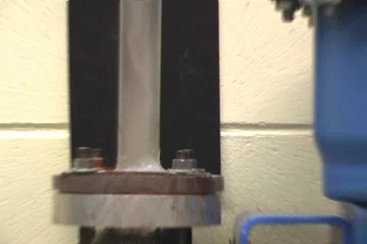
4 Guideline for Proper Valve Sizing Death by oversizing Seat is eroded away Segment shows signs of erosion 4

5 Guideline for Proper Valve Sizing Death by oversizing Hole in body Seat is eroded away Erosion pattern in body 5
 Water (Liquid) Triple Point Water Vapor (gas) 6.")
6 Cavitation Definition of Cavitaion Each liquid has a different pressure and temperature at which it boils (or vaporizes). Water for example at atmospheric pressure will boil at 100 C (212 F). Dropping the pressure inside of a valve for example can effect the temperature at which a liquid will boil. 1 atm Pressure.006 atm Ice (solid) Water (Liquid) Triple Point Water Vapor (gas) 6.01 C Temperature 100 C
7 Cavitation P 1 P VC P 2 A valve is represented as a simple orifice plate to represent a restriction in the flow path Pressure Velocity Vapor Pressure Because of the law of conservation of energy, when the velocity of the liquid increases through the valve, the pressure must decrease 7
8 Cavitation P 1 P VC P 2 Pressure P 1 P 2 Velocity Vapor Pressure Cavitation occurs when the pressure inside the valve drops below the vapor pressure of the liquid, allowing the liquid to turn into a gas. 8

9 Pressure Shock Generation Mechanisms 9
10 10


11 Cavitation The damage caused by cavitation is very rough and pitted and can occur quickly. 11
12 Pressure Recovery Factor F L The Pressure Recovery Factor of the valve indicates the size of the pressure recovery relative to P VC and P 2. P 1 P VC P 2 A valve is represented as a simple orifice plate to represent a restriction in the flow path P 1 P 1 P 2 F L = P 1 -P 2 P 1 -P VC P 2 Pressure Recovery P 2 P VC P VC 12
13 Pressure Recovery Factor F L A high recovery valve (similar to the red line) has a greater recovery from P VC to P 2. This can mean the valve is more likely to experience problems with cavitation. The higher the pressure recovery factor (F L ) the lower the recovery of the valve and the better the valve is able to avoid cavitation and noise issues. P 1 Higher F L (Low Recovery) Lower F L (High Recovery) P 2 Pressure Recovery P 2 P VC P VC 13
14 Pressure Recovery Factor F L P 1 = 15 P 1 -P 2 P 2 = 10 Pressure Recovery F L = P 1 -P 2 P 1 -P VC P 2 -P VC P VC = 5 = = 5 =.5 =
15 Pressure Recovery Factor F L F L = P 1 -P 2 P 1 -P VC P 1 -P 2 P 1 = 15 P 2 -P VC P 2 = 10 P VC = 8 P VC = 5 = = 5 =.714 =


16 Valve Geometry Effects F L Turbulence and friction cause permanent pressure loss VELOCITY CHANGE DIRECTION CHANGE P 1 P 2 P 1 P 2 P V Vapor Pressure P V Vapor Pressure


17 Valve Geometry Effects F L MOSTLY VELOCITY CHANGE DIRECTION & VELOCITY CHANGE P 1 P 1 P2 P2 P V Vapor Pressure P V Vapor Pressure
18 Pressure Recovery Factor F L 1 Recovery Factor, FL H.P. Butterfly Globe Ecc. Plug Ball Percent Open 18
19 Sizing w/ Orifice Plates p2 P1 Pi P2 Vapor pressure Lowest system pressure w/o plate Lowest system pressure with plate 19


20 Design Features Variable Resistor in Valve 20
21 21
22 Design Features Variable Resistor vs. Fixed Resistor A typical defined process tells us the largest dp a valve will experience will typically be on the minimum flow A fixed resistor must be sized for the maximum flow, so it s most effective on lower dp s If a liquid application is going to cavitate often times they do on a minimum / startup flow Pressure P O P Pump Curve P m System Curve System Pressure Drop 22 Q min Q max Flowrate

23 Flashing Issue with oversized valve Caused when the downstream pressure is below the vapor pressure of the liquid. Similar to cavitation, vapor bubbles form, but unlike cavitation the vapor pressure never recovers high enough for the vapor bubbles to implode Vapor bubble remain mixed in the media and travel downstream 23
24 Flashing (Liquid) P1 Pvc P2 Pressure P1 Velocity Vapor pressure P2 24


25 Flashing Damage Typically, damage potential of flashing is smaller than in cavitation. Damages are erosion type wear, smooth grooves and cavities. 25


26 Flashing Solutions It s important to understand flashing is caused by the process, not the valve. Therefore there isn t anything you can do to stop the valve from flashing, it has to be a process change. To prevent flashing damage to the body we turn the valve to the FTC or non-preferred direction. When flashing occurs it will hit the seat of the valve, instead of the body. The seat is made of a harder material, and easier to replace, thus less damaging. 26
 FTC direction 27 Valve Discharging Directly into")
27 Flashing - conclusions Rotary valves FTC direction Hardened trim, SST body Discharging into vessel if possible Wide valve openings Limit flow velocities Enlarger downstream pipe No Q-trim in clear flashing service (P2 << Pv) FTC direction 27 Valve Discharging Directly into Vessel
Cavitation in Valves
 VM CAV/WP White Paper Cavitation in Valves Table of Contents Introduction............................... 2 Cavitation Analysis.......................... 2 Cavitation Data............................. 3
TUTORIAL. NPSHA for those who hate that stuffy word. by Jacques Chaurette p. eng. copyright 2006
 TUTORIAL NPSHA for those who hate that stuffy word by Jacques Chaurette p. eng. www.lightmypump.com copyright 2006 page.2 NPSHA for those who hate that stuffy word This article follows the same approach
DFT Valves. Selecting Control Valves
 DFT Valves Selecting Control Valves Evaluating Process Conditions in Control Valve Selection A one-size-fits-all approach is not the best way to go about choosing the proper control valve for a particular
Safeguarding your process flow control system
 Safeguarding your process flow control system 1 Cavitation Understanding Flashing and Cavitation and flashing are major causes of metal erosion in flow control systems. It occurs when a media goes through
The Discussion of this exercise covers the following points:
 Exercise 3-2 Orifice Plates EXERCISE OBJECTIVE In this exercise, you will study how differential pressure flowmeters operate. You will describe the relationship between the flow rate and the pressure drop
This portion of the piping tutorial covers control valve sizing, control valves, and the use of nodes.
 Piping Tutorial A piping network represents the flow of fluids through several pieces of equipment. If sufficient variables (flow rate and pressure) are specified on the piping network, CHEMCAD calculates
Restriction Orifice. Single or Multi Stage Orifice to. Reduce Pressure or. Limit the Flow Rate
 Restriction Orifice Single or Multi Stage Orifice to Reduce Pressure or Limit the Flow Rate Restriction Orifice Plates Series ROPS Principle Restriction Orifice Plates and Critical Flow Devices and their
(Refer Slide Time: 2:16)
") Fluid Machines. Professor Sankar Kumar Som. Department Of Mechanical Engineering. Indian Institute Of Technology Kharagpur. Lecture-23. Diffuser and Cavitation. Good morning and welcome you all to this
Fluid Machines. Professor Sankar Kumar Som. Department Of Mechanical Engineering. Indian Institute Of Technology Kharagpur. Lecture-23. Diffuser and Cavitation. Good morning and welcome you all to this
Appendix A Frequently Asked Questions
 Appendix A Frequently Asked Questions This set of Frequently Asked Questions has been supplied courtesy of Mitech Spirex Sarco Ltd, South Africa, with acknowledgements and thanks to Michael Sessions. Questions
How to use the PBM Flow Calculator Spreadsheet (V2.04)
") How to use the PBM Flow Calculator Spreadsheet (V2.04) o Navigate to the F:\Common\ENGINEERING\Common Design Calculations folder o o Open PBM FLOW CALC 2.04.xlsm On the title page, the version, version
How to use the PBM Flow Calculator Spreadsheet (V2.04) o Navigate to the F:\Common\ENGINEERING\Common Design Calculations folder o o Open PBM FLOW CALC 2.04.xlsm On the title page, the version, version
Aspects of Flow Control in Metering Henry Gomes SGS Kuwait WLL
 Aspects of Flow Control in Metering Henry Gomes SGS Kuwait WLL HENRY GOMES Metering Consultant SGS Kuwait Born on Aruba (Carribean) in 1963 School and College in the Netherlands Resident in Romania - Bucharest
INDIAN INSTITUTE OF TECHNOLOGY KHARAGPUR NPTEL ONLINE CERTIFICATION COURSE. On Industrial Automation and Control
 INDIAN INSTITUTE OF TECHNOLOGY KHARAGPUR NPTEL ONLINE CERTIFICATION COURSE On Industrial Automation and Control By Prof. S. Mukhopadhyay Department of Electrical Engineering IIT Kharagpur Topic Lecture
INTRODUCTION TO REGULATOR AND RELIEF VALVE SIZING. Introduction
 INTRODUCTION TO REGULATOR AND RELIEF VALVE SIZING MARK DYKOFF MANAGER, GAS REGULATION AND CONTROL CALTROL, INC. Introduction Regulators used in natural gas applications are devices made up of a valve and
Balancing HVAC Hydronic Systems Part 3: Flow Measurement Valves
 Balancing HVAC Hydronic Systems Part 3: Flow Measurement Valves Monday Morning Minutes by Norm Hall, August 20, 2018 The flow balance of a hydronic system is a critical component in the commissioning of
Cost Effective. Responsiveness to Customer
 Severe Service When you partner with Trimteck you can expect: Cost Effective Made in USA High Quality Applications Support Quick Delivery Responsiveness to Customer About Trimteck Trimteck is a family-owned
Practical Guide. By Steven T. Taylor, P.E., Member ASHRAE
 ractical Guide The following article was published in ASHRAE Journal, March 2003. Copyright 2003 American Society of Heating, Refrigerating and Air- Conditioning Engineers, Inc. It is presented for educational
CONTROL VALVE WHAT YOU NEED TO LEARN?
 CONTROL VALVE WHAT YOU NEED TO LEARN? i) The control valve characteristics refers to the relationship between the volumetric flowrate F (Y-axis) through the valve AND the valve travel or opening position
Application Worksheet
 Application Worksheet All dimensions are nominal. Dimensions in [ ] are in millimeters. Service Conditions Medium Through Valve: Required C v : Temperature Maximum: Minimum: Normal: Flow Maximum: Minimum:
Hydronic Systems Balance
 Hydronic Systems Balance Balancing Is Misunderstood Balancing is application of fundamental hydronic system math Balance Adjustment of friction loss location Adjustment of pump to requirements By definition:
The Discussion of this exercise covers the following points: Pumps Basic operation of a liquid pump Types of liquid pumps The centrifugal pump.
 Exercise 2-3 Centrifugal Pumps EXERCISE OBJECTIVE In this exercise, you will become familiar with the operation of a centrifugal pump and read its performance chart. You will also observe the effect that
Understanding Net Positive Suction Head
 Understanding Net Positive Suction Head Atmospheric Pressure Until the early 17 th century air was largely misunderstood. Evangelista Torricelli, an Italian scientist, was one of the first to discover
FACHGESPRÄCH 3 NPSH NPSH3. Let us call it: CAVITATION A LOOK UNDER THE HOOD
 FACHGESPRÄCH 3 NPSH Let us call it: NPSH3 CAVITATION A LOOK UNDER THE HOOD OUR APPROACH TO LEARNING AT THIS PRESTIGIOUS W.T.F. FORMULAS DEFINITIONS B.U.T.Ts Broadly Useful Technical Tips T.I.T.S T.I.T.S
Pressure and Flow Control Valves DBGM, German and European Patents
 Pressure and Flow Control Valves DBGM, German and European Patents Absolutely Reliable Pressure and Flow Control In water mains of sizes DN 50 to DN 150, ERHARD Control Valves in straight or angle pattern
Process Dynamics, Operations, and Control Lecture Notes - 20
 Lesson 0. Control valves 0.0 Context Controller output is a signal that varies between 0 and 100%. Putting this signal to use requires a final control element, a device that responds to the controller
Control Valve Sizing. Sizing & Selection 3 P 1. P 2 (Outlet Pressure) P V P VC. CONTENTS Introduction Nomenclature Calculating C v
 P V P VC. CONTENTS Introduction Nomenclature Calculating C v") Sizing & Selection 3 Control Valve Sizing CONTENTS Introduction 3-1 Nomenclature 3-1 Calculating for Liquids 3-3 Liquid Sizing Examples 3-7 Calculating for Gases 3-10 Gas Sizing Examples 3-13 Calculating
Sizing & Selection 3 Control Valve Sizing CONTENTS Introduction 3-1 Nomenclature 3-1 Calculating for Liquids 3-3 Liquid Sizing Examples 3-7 Calculating for Gases 3-10 Gas Sizing Examples 3-13 Calculating
Exercise 4-2. Centrifugal Pumps EXERCISE OBJECTIVE DISCUSSION OUTLINE DISCUSSION. Pumps
 Exercise 4-2 Centrifugal Pumps EXERCISE OBJECTIVE Familiarize yourself with the basics of liquid pumps, specifically with the basics of centrifugal pumps. DISCUSSION OUTLINE The Discussion of this exercise
Stormy Phillips BASICS OF LEASE AUTOMATIC CUSTODY TRANSFER (LACT) SYSTEMS
 SYSTEMS") Stormy Phillips BASICS OF LEASE AUTOMATIC CUSTODY TRANSFER (LACT) SYSTEMS Why is Stormy Walking Funny?? What is a LACT system? Introduction A LACT unit is a group of equipment designed specifically for
Stormy Phillips BASICS OF LEASE AUTOMATIC CUSTODY TRANSFER (LACT) SYSTEMS Why is Stormy Walking Funny?? What is a LACT system? Introduction A LACT unit is a group of equipment designed specifically for
Using the CONVAL software for the petrochemical plant control valves checking. Case study
 Using the CONVAL software for the petrochemical plant control valves checking. Case study C. Patrascioiu, G. Stamatescu, C. Lazar Abstract In the paper there are presented the researches into field of
Operational Settings:
 instrucalc features more than 70 routines associated with control valves, ISO flow elements, relief valves and rupture disks, and calculates process data at flow conditions for a comprehensive range of
Pumping Systems for Landscaping Pumps, Controls and Accessories. Mark Snyder, PE
 October 21, 2010 Pumping Systems for Landscaping Pumps, Controls and Accessories Mark Snyder, PE Pump Station Design Purpose of Pump Stations Pump stations are designed to boost water pressure from a lower
BACK PRESSURE / SUSTAINING
 In many liquid piping systems, it is vital that line pressure is maintained within relatively narrow limits. This is the function of the 108 Pressure Relief / Back Pressure Series of the OCV control valves.
THE INNER WORKINGS OF A SIPHON Jacques Chaurette p. eng. January 2003
 THE INNER WORKINGS OF A SIPHON Jacques Chaurette p. eng. www.lightmypump.com January 2003 Synopsis The objective of this article is to explain how a siphon works. The difference between low pressure, atmospheric
BACK PRESSURE / SUSTAINING
 SPECIFICATIONS DIMENSIONS In many liquid piping systems, it is vital that line pressure is maintained within relatively narrow limits. This is the function of the 108 Pressure Relief / Back Pressure Series
Workshop 302-compressor-anti-surge
 Workshop Objectives Workshop 302-compressor-anti-surge Illustrate how to create a simple anti-surge control on a compressor Workshop Description Flowsheeet: A feed stream at 1 bar with methane, ethane
fserve. Experience In Motion
 Experience In Motion 1 Index Section Page 1 to Cavitation... 3 2 Product Comparison... 7 3 DiamondBack... 10 4 ChannelStream... 11 5 Multi-Z... 12 6 CavControl... 13 7 SideWinder... 13 8 CavStream... 14
Engineering / Technical Section
 TABLE OF CONTENTS Valve Dimensions...E-2 ANSI Flange Data...E-3 Performance Charts...E-4 - E-8 Cavitation Information...E-9 Metric Valve Dimensions...E-10 DIN Flange Data...E-11 - E-12 Metric Conversion
Chapter 16 Test. Directions: Write the correct letter on the blank before each question.
 Chapter 16 Test Name: Date: Directions: Write the correct letter on the blank before each question. Objective 1: Explain the way vaporization and steam relate to the extinguishing properties of water.
THE INFLOW OF UNWANTED AIR
 IN PRESSURIZED PIPES The main reason for the inflow of air in public water distribution systems is excessive water velocity. Air traveling with water in pressurized pipes can result in high turbulence
Modeling a Pressure Safety Valve
 Modeling a Pressure Safety Valve Pressure Safety Valves (PSV), Pressure Relief Valves (PRV), and other pressure relieving devices offer protection against overpressure in many types of hydraulic systems.
DANFLO Control Valves 400 Series Model 20
 DANFLO Control Valves 400 Series Model 20 Back Pressure/Pressure Relief The DANFLO Model 20 is a pilot operated valve suitable for use in gas or liquid facilities and requires no outside power for operation.
Injector Dynamics Assumptions and their Impact on Predicting Cavitation and Performance
 Injector Dynamics Assumptions and their Impact on Predicting Cavitation and Performance Frank Husmeier, Cummins Fuel Systems Presented by Laz Foley, ANSYS Outline Overview Computational Domain and Boundary
A centrifugal pump consists of an impeller attached to and rotating with the shaft and a casing that encloses the impeller.
 Centrifugal pump How centrifugal pumps work A centrifugal pump consists of an impeller attached to and rotating with the shaft and a casing that encloses the impeller. In centrifugal pump, liquid is forced
VB-7211 Series. Application. Features. Applicable Literature. 1/2" to 1-1/4" Union End NPT Stem Up Open, Two-Way Valves General Instructions
 TAC 1354 Clifford Avenue P. O. Box 2940 Loves Park, IL 61132-2940 www.tac.com VB-7211 Series 1/2" to 1-1/4" Union End NPT Stem Up Open, Two-Way Valves General Instructions Application VB-7211 series stem
NAF-Trimball Control Ball Valves
 NAF-Trimball Control Ball Valves Size DN 50-500, Size 2-20 PN 10 40, ANSI Class 150 and 300 Fk 41.65(9)GB 11.04 Primary characteristics The NAF-Trimball represents an entirely new approach for addressing
Anti-Cavitation Trim. Eliminates cavitation damage Reduces noise Preserves valve and surrounding pipe systems. singervalve.com
 Anti-Cavitation Trim Eliminates cavitation damage Reduces noise Preserves valve and surrounding pipe systems Say Goodbye to Cavitation Damage! Cavitation, a common problem in pumps and control valves,
TECHNICAL DATA. Notes: For use with Trim Charts on Pages 2-4
 Page 1 of 5 Telephone: 29-95-9501 Technical Services: 877-8-5 Fax: 29-8-0 Email: techsvcs@vikingcorp.com Model F Dry Valve with Trim Valve Size Part Number 17PTR 175PTR 17PTR Standard Trim Sets include
Spring Loaded Regulators Constant Loaded Regulators Twin Parallel Flow Regulators Field Service Regulators
 Product Line Brochure J0B Effective Date 2/01 Spring Loaded Regulators Constant Loaded Regulators Twin Parallel Flow Regulators Field Service Regulators P R O D U C T L I N E O V E R V I E W Regulator
Characterizers for control loops
 Characterizers for control loops By: F. G. Shinskey (May 1999) Introduction Commercial controllers such as the PID series (proportional, integral, derivative, and their combinations) are linear devices
Pneumatic Conveying Systems Theory and Principles Session 100
 Pneumatic Conveying Systems Theory and Principles Session 100 1 Controls & Instrumentation P = Actual Pressure V = Actual Volume T is Typically Ignored Key Relationship PV/T Terminal Point Any Point Pick
Valves. Controllers. Valves Two Types
 Hydraulics Taking the Irritation out of Irrigation My plants are getting irrigated, so I m all set, right? Marcus Duck Academic Advisor, Instructor & Program Coordinator MSU s 2-year Horticulture Programs
VB-7323 Series. Application. Features. Applicable Literature. 1/2 to 2 Screwed NPT Three-Way Diverting Valves General Instructions
 VB-7323 Series 1/2 to 2 Screwed NPT Three-Way Diverting Valves General Instructions Application VB-7323 series three-way diverting valves control hot or chilled water in heating or air conditioning systems.
SAMSON SOLUTIONS Energy and Power (Critical Applications)
") SAMSON SOLUTIONS Energy and Power (Critical Applications) Speakers: Ing. Gianluigi Rossi Ing. Stefano Salvadori Managing Director - SAMSON Italy Head of Sales and Project Department - SAMSON Italy MARKET
SAMSON SOLUTIONS Energy and Power (Critical Applications) Speakers: Ing. Gianluigi Rossi Ing. Stefano Salvadori Managing Director - SAMSON Italy Head of Sales and Project Department - SAMSON Italy MARKET
WW-730. Pressure Sustaining/Relief Control Valve
 WW-730 Pressure Sustaining/Relief Control Valve Installation Operation & Maintenance Page 1 of 6 1. DESCRIPTION The Model 730 Pressure Relief / Sustaining Valve is an automatic control valve designed to
SINGLE VALVE WITH LOW-FLOW BYPASS
 CONTROL VALVES Pressure Reducing Valve Sizing Guide Sizing pilot operated reducing valves is not a complicated process. It starts with determining requirements and following these guidelines in valve size
API th Edition Ballot Item 7.8 Work Item 4 Gas Breakthrough
 API 521 7 th Edition Ballot Item 7.8 Work Item 4 Gas Breakthrough NOTE: This is a reballot of previously approved API 521 7 th Edition Ballot Item 6.3 which was modified based on comments. Comments should
ADVANCED CONTROL VALVE AND ACTUATOR: Selection, Calculations, Sizing, Applications, Operation, Diagnostic Testing, Troubleshooting and Maintenance.
 Training Title ADVANCED CONTROL VALVE AND ACTUATOR: Selection, Calculations, Sizing, Applications, Operation, Diagnostic Testing, Troubleshooting and Maintenance. Training Duration 5 days Training Dates
Cash Valve TYPE KP PILOT OPERATED BACK PRESSURE VALVE. ISSUED - DECEMBER 2000 CAVMC-0518-US-0208 ISO 9001 Certified
 Cash Valve PILOT OPERATED BACK PRESSURE VALVE ISSUED - DECEMBER 2000 CAVMC-0518-US-0208 ISO 01 Certified KP HIGH CAPACITY PILOT OPERATED BACK PRESSURE VALVE DESCRIPTION The Cash Valve Type KP is a pilot
Engineering Letter. Pump Protection
 Engineering Letter Pump Protection Content 1. Introduction...1 1.1 What systems are available to ensure the minimum flow through the pump at all times?...2 1.1.1 Continuous Bypass System...2 1.1.2 Controlled
VB-7212 Series. Application. Features. Applicable Literature. 5/8" O.D., 45 SAE Flared Stem Up Open, Two-Way Valves General Instructions
 VB-7212 Series 5/8" O.D., 45 SAE Flared Stem Up Open, Two-Way Valves General Instructions Application VB-7212 series single seat, stem up open, two-way valves control water from 20 to 281 F (-7 to 138
RELIEF VALVES IN PARALLEL
 RELIEF VALVES IN PARALLEL Mary Kay O'Connor Process Safety Center International Symposium BEYOND REGULATORY COMPLIANCE MAKING SAFETY SECOND NATURE October 26-28, 2010 James R. Lawrence Sr. Why use a Relief
PILOT OPERATED RELIEF VALVE SAFETY PRODUCTS THAT PROTECT EQUIPMENT, LIVES & THE ENVIRONMENT
 PILOT OPERATED RELIEF VALVE SAFETY PRODUCTS THAT PROTECT EQUIPMENT, LIVES & THE ENVIRONMENT Model Number Model Description Page # Pilot operated Relief Valves Pilot Operated Relief Valves 3-27 Operation
HOW TO NOT MEASURE GAS - ORIFICE. Dee Hummel. Targa Resources
 HOW TO NOT MEASURE GAS - ORIFICE Dee Hummel Targa Resources Introduction Measuring natural gas is both a science and an art. Guidelines and industry practices explain how to accurately measure natural
Back to Basics: Pumping Systems RM ASHRAE TECH CONFERENCE
 Back to Basics: Pumping Systems RM ASHRAE TECH CONFERENCE 4/29/2016 1 AGENDA Closed loop heating and cooling piping systems Expansion Tanks Pumps 2 BASIC PUMPING LOOP Nice and simple too simple? Constant
Sizing Pulsation Dampeners Is Critical to Effectiveness
 Sizing Pulsation Dampeners Is Critical to Effectiveness Pressure variation is an important consideration when determining the appropriate size pulsation dampener needed for an application. by David McComb,
DN300 DN2000 C Plunger Valve
 ל DN300 DN2000 C Plunger Valve P.O.B 46 MOSHAV SHTULA WESTERN GALILEE 2286500 Tl. +972-(0)77-6656101, Fax. +972-(0)77-6656196 Website: www.saisanketvalves.com www.saisanket.com email: saisanket@saisanket.com
Pressure and/or Temperature Pilot Operated Steam Regulators Series 2000
 Hoffman Specialty Regulators Regulators Pressure and/or Temperature Operated Regulators Series 2000 The Hoffman Specialty Series 2000 consists of main valves, pilot valves, wells and hardware kits. They
Pressure reducing valves Index
 Index General information page Introduction 506 General introduction 507 for a steam plant 509 Product information BSP thread page Brass 510 ; BSP female thread 511 ; BSP male thread 513 Stainless steel
PUMP CONSULTING & TRAINING LLC Joseph R. Askew 1811 Stonecrest Ct. Lakeland, Fl
 PUMP CONSULTING & TRAINING LLC Joseph R. Askew 1811 Stonecrest Ct. Lakeland, Fl. 33813 863-644-3118 E-mail: pmpcnslt@tampabay.rr.com June 10, 2006 Phosphate Conference Clearwater Convention June 2006 Presentation
SABERINDO PACIF SABERINDO PACIFIC CIFIC SABERINDO PA. A Tyco International Company
 CIF A Tyco International Company 1 Foam Concentrate CIF 3% AFFF -UL Listed -UL Canada Listed 6% AFFF 6 parts AFFF concentrate to 94 parts water -UL Listed- Foam Liquid -UL Canada Listed 3% FLUOROPROTEIN
CASH VALVE TYPE KP BACK PRESSURE VALVES
 A high capacity pilot operated back pressure valve that offers accurate control and dependable protection against overpressure conditions FEATURES Automatically maintains maximum pressure in a vessel or
VB-7213 Series. Application. Features. Applicable Literature. 1/2" to 2" Screwed NPT Stem Up Open, Two-Way Valves General Instructions
 VB-7213 Series 1/2" to 2" Screwed NPT Stem Up Open, Two-Way Valves General Instructions Application VB-7213 series single seat, stem up open, two-way valves control water from 20 to 281 F (-7 to 138 C)
Tirpur Area Water Supply Project A Report on Transient Modeling Study
 y February 2008 1 of 81 y INTRODUCTION: The report presents results from a transient modeling study conducted on the clear water transmission main of Tirpur Areas Water Supply Project, Tamilnadu, India.
Control Valves, Actuators, & Pressure Safety Valves
 A Successful 4-Day In-house Training Course Control Valves, Actuators, & Pressure Safety Valves 14-MAR-17 This course is Designed, Developed, and will be Delivered under iso Quality Standards Control Valves,
Air Eliminators and Combination Air Eliminators Strainers
 Description Air Eliminators and Combination Air Eliminator Strainers are designed to provide separation, elimination and prevention of air in piping systems for a variety of installations and conditions.
H o w t o U s e a R e g u l a t o r t o R e d u c e T i m e D e l a y i n a n A n a l y t i c a l S y s t e m
 H o w t o U s e a R e g u l a t o r t o R e d u c e T i m e D e l a y i n a n A n a l y t i c a l S y s t e m By Doug Nordstrom and Mike Adkins Swagelok Company Process measurements are instantaneous but
The capacity of the cargo tank venting system (46 CFR );
;") INDUSTRY GUIDELINES FOR DETERMINING THE MAXIMUM LIQUID TRANSFER RATE FOR A TANK VESSEL TRANSFERRING A FLAMMABLE OR COMBUSTIBLE CARGO USING A VAPOR CONTROL SYSTEM This document provides guidance from the
INDUSTRY GUIDELINES FOR DETERMINING THE MAXIMUM LIQUID TRANSFER RATE FOR A TANK VESSEL TRANSFERRING A FLAMMABLE OR COMBUSTIBLE CARGO USING A VAPOR CONTROL SYSTEM This document provides guidance from the
Chapter 10: Bidirectional Flow Controls
 Chapter 10: Bidirectional Flow Controls Objectives Learn about the patented, bidirectional flow control valves. Understand how the flow force affects the performance of the ZL70-36. Learn why there is
TECHNICAL DATA. the Viking Pilot Pressure Regulating Valve 1 Model A-1 Speed Control Assembly: OBSOLETE. the Viking Speed Control Assembly 1
 November 30, 1994 534 a 1. PRODUCT NAME VIKING 2" (50mm), 3" (75mm), 4" (100mm), 6" (150mm) 2. MANUFACTURER THE VIKING CORPORATION 210 N. Industrial Park Road Hastings, Michigan 49058 U.S.A. Telephone:
S.A. Klein and G.F. Nellis Cambridge University Press, 2011
 16-1 A flow nozzle is to be used to determine the mass flow rate of air through a 1.5 inch internal diameter pipe. The air in the line upstream of the meters is at 70 F and 95 psig. The barometric pressure
HOW TO MANAGE VAPORIZATION IN AN ANALYTICAL SYSTEM By Dean Slejko and Tony Waters
 HOW TO MANAGE VAPORIZATION IN AN ANALYTICAL SYSTEM By Dean Slejko and Tony Waters If the analyzer in your analytical system requires gas but your sample is liquid, the only option is to convert the liquid
OWNER S TECHNICAL MANUAL
 EL SERIES OWNER S TECHNICAL MANUAL DP7002 1 Air Operated Diaphragm Pump Description The DP7002 1 air operated diaphragm pump is the ideal device for the pumping, transfer and dispensing of chemical liquids,
APPLYING VARIABLE SPEED PRESSURE LIMITING CONTROL DRIVER FIRE PUMPS. SEC Project No
 APPLYING VARIABLE SPEED PRESSURE LIMITING CONTROL DRIVER FIRE PUMPS SEC Project No. 1803007-000 November 20, 2006 TABLE OF CONTENTS I. ABSTRACT...1 II. INTRODUCTION...1 III. HISTORY...2 IV. VARIABLE SPEED
INSTALLATION, OPERATION AND MAINTENANCE MANUAL
 3200-300 INSTALLATION, OPERATION AND MAINTENANCE MANUAL PLEASE READ CAREFULLY YOUR WARRANTY MAY BE VOID IF INSTRUCTIONS ARE NOT FOLLOWED Note: when ordering parts give pump model and serial number Cornell
Pressure Control. where: p is the pressure F is the normal component of the force A is the area
 Pressure Control First of all, what is pressure, the property we want to control? From Wikipedia, the free encyclopedia. Pressure is the application of force to a surface, and the concentration of that
MEMORIAL UNIVERSITY OF NEWFOUNDLAND Faculty of Engineering and Applied Science FLUID MECHANICS LABORATORY PIPE FRICTION
 MEMORIAL UNIVERSITY OF NEWFOUNDLAND Faculty of Engineering and Applied Science FLUID MECHANICS LABORATORY PIPE FRICTION Objective To estimate the fluid pressure drops and roughness specifications for copper
FUNDAMENTALS OF PRESSURE REGULATORS ROBERT BENNETT MANAGER OF TRAINING ELSTER AMERICAN METER
 FUNDAMENTALS OF PRESSURE REGULATORS ROBERT BENNETT MANAGER OF TRAINING ELSTER AMERICAN METER SUPPLY = DEMAND FUNCTION OF A REGULATOR A regulator may be defined as a "mechanism for controlling or governing
Gerald D. Anderson. Education Technical Specialist
 Gerald D. Anderson Education Technical Specialist The factors which influence selection of equipment for a liquid level control loop interact significantly. Analyses of these factors and their interactions
TECHNICAL DATA PILOT PRESSURE REGULATED DELUGE SYSTEM CONTROLLED BY PNEUMATIC RELEASE. 1. DESCRIPTION (Refer to Figures 1, 2 or 3.
 Page 1 of 8 1. DESCRIPTION A Viking Pilot Pressure Regulated Deluge System utilizes a Viking Flow Control Valve to control water flow into the deluge system. The flow control valve must be installed with
FE Petro vs. New Red Jacket Competitive Comparison
 FE Petro vs. New Red Jacket Competitive Comparison Price & Performance Comparison 1-1/2 HP FE Petro vs. New Red Jacket 140 120 1-1/2 HP Fixed Speed Pump Performance FE Petro STP150 "New" Red Jacket P150U1
Reliable System Performance PM valves
 MAKING MODERN LIVING POSSIBLE Service manual Reliable System Performance PM valves Danfoss components are designed to give a high level of performance over an extended operating life. When Danfoss develops
TEST SPECIFICATION NYT-909-C
 748 Starbuck Ave, Watertown, NY 13601 Phone: +1-315-786-5200 Engineering Fax: +1-315-786-5673 TEST SPECIFICATION NYT-909-C CODE OF TESTS FOR TESTING "AB" TEST RACK P/N 702546 & 702612 ISSUE NO. 5 1.0 THE
Operating Instructions
 Operating Instructions Note: 1. Never let the centrifugal pump run dry. 2. Make sure that there is at least one open path for water flow in the pipe network before turning the pump on. Never run the pump
International Journal of Technical Research and Applications e-issn: , Volume 4, Issue 3 (May-June, 2016), PP.
, PP.") DESIGN AND ANALYSIS OF FEED CHECK VALVE AS CONTROL VALVE USING CFD SOFTWARE R.Nikhil M.Tech Student Industrial & Production Engineering National Institute of Engineering Mysuru, Karnataka, India -570008
DESIGN AND ANALYSIS OF FEED CHECK VALVE AS CONTROL VALVE USING CFD SOFTWARE R.Nikhil M.Tech Student Industrial & Production Engineering National Institute of Engineering Mysuru, Karnataka, India -570008
Training Fees 4,000 US$ per participant for Public Training includes Materials/Handouts, tea/coffee breaks, refreshments & Buffet Lunch.
 Training Title CONTROL & SAFETY RELIEF VALVES Training Duration 5 days Training Venue and Dates Control & Safety Relief Valves 5 06-10 May, 2018 $4,000 Dubai, UAE Trainings will be conducted in any of
REFERENCE GUIDE. Rev. 0 15/09/2016
 VALVE SIZING CALCULATOR REFERENCE GUIDE Rev. 0 15/09/2016 Copyright HIT VALVE S.p.A. 2016 All rights reserved. No part of this publication may be reproduced, stored in a retrieval system, or transmitted,
Selecting Controls for Water Distribution Systems
 Utah State University DigitalCommons@USU Reports Utah Water Research Laboratory January 1994 Selecting Controls for Water Distribution Systems J. Paul Tullis Follow this and additional works at: https://digitalcommons.usu.edu/water_rep
Pump Selection and Sizing (ENGINEERING DESIGN GUIDELINE)
") Guidelines for Processing Plant Page : 1 of 64 Feb 2007 (ENGINEERING DESIGN GUIDELINE) Author: A L Ling Checked by: Karl Kolmetz TABLE OF CONTENT INTRODUCTION Scope 5 General Design Consideration Type
Guidelines for Processing Plant Page : 1 of 64 Feb 2007 (ENGINEERING DESIGN GUIDELINE) Author: A L Ling Checked by: Karl Kolmetz TABLE OF CONTENT INTRODUCTION Scope 5 General Design Consideration Type
700 SIGMA SERIES ENGINEERING DATA
 700 SIGMA SERIES ENGINEERING DATA CONTENT 700 SIGMA EN/ES 2-8 700 SIGMA EN/ES 2 Exploded View 3 Material Specifications 4 Principle of Operation 5 Plug Options 6 Cavitation 7 Cavitation Cage 8 700 SIGMA
Flow in a shock tube
 Flow in a shock tube April 30, 05 Summary In the lab the shock Mach number as well as the Mach number downstream the moving shock are determined for different pressure ratios between the high and low pressure
my SYSTEM A guide to common applications in water distribution systems
 my SYSTEM A guide to common applications in water distribution systems WWW.SINGERVALVE.COM INDEX This short guide is intended to offer guidance on some of the common problems, applications and questions