Mounting and Operating Instructions EB 8020 EN. Type Gas and Type Gas Automatic Shut-off Valves for Gases
|
|
|
- Rosamund Hart
- 5 years ago
- Views:
Transcription
1 Type Gas and Type Gas Automatic Shut-off Valves for Gases Valve class D and valve class E Translation of original instructions Type Gas with Type 3963 Solenoid Valve and Type 3730 Positioner Mounting and Operating Instructions Edition January 2018

2 Note on these mounting and operating instructions These mounting and operating instructions assist you in mounting and operating the device safely. The instructions are binding for handling SAMSON devices. For the safe and proper use of these instructions, read them carefully and keep them for later reference. If you have any questions about these instructions, contact SAMSON s After-sales Service Department (aftersalesservice@samson.de). The mounting and operating instructions for the devices are included in the scope of delivery. The latest documentation is available on our website ( > Product documentation. You can enter the document number or type number in the [Find:] field to look for a document. Definition of signal words! DANGER Hazardous situations which, if not avoided, will result in death or serious injury! WARNING Hazardous situations which, if not avoided, could result in death or serious injury! NOTICE Property damage message or malfunction Note Additional information Tip Recommended action 2
3 Contents 1 Safety instructions and measures Notes on possible severe personal injury Notes on possible personal injury Notes on possible property damage Markings on the control valve Nameplate for gas version Valve nameplate Actuator nameplate Other markings DVGW register number Material number Position of marking Design and principle of operation Fail-safe positions Versions Technical data Common technical data Technical data of version for valve class D Technical data of version for valve class E Measures for preparation Unpacking Transporting and lifting Transporting Lifting Storage Preparation for installation Mounting and start-up Mounting the actuator onto the valve Installing the valve into the pipeline Checking the installation conditions Additional fittings Installing the control valve
4 Contents 5.3 Quick check Operation Servicing Replacing the gasket Other service work Aligning the V-port plug Cleaning the strainer Testing the control valve Preparation for return shipment Ordering spare parts and operating supplies Malfunctions Troubleshooting Emergency action Decommissioning and disassembly Decommissioning Removing the valve from the pipeline Removing the actuator from the valve Disposal Appendix After-sales service Certificates Spare parts
5 Safety instructions and measures 1 Safety instructions and measures Intended use The SAMSON Type 3241G Globe Valve in combination with the Type 3271 or Type 3277 Pneumatic Actuator and a solenoid valve is designed to regulate the flow rate, pressure or temperature of fuel gases in gas-consuming equipment. The valve, actuator, and solenoid valve are designed to operate under exactly defined conditions (e.g. operating pressure, process medium, temperature). Therefore, operators must ensure that the control valve is only used in applications that meet the specifications used for sizing the valve at the ordering stage. In case operators intend to use the control valve in other applications or conditions than specified, SAMSON must be contacted. SAMSON does not assume any liability for damage resulting from the failure to use the valve for its intended purpose or for damage caused by external forces or any other external factors. Refer to the technical data and nameplate for limits and fields of application as well as possible uses. Reasonably foreseeable misuse The control valve is not suitable for the following applications: Use outside the limits defined during sizing and in the technical data Use outside the limits defined by the valve accessories mounted on the control valve Furthermore, the following activities do not comply with the intended use: Use of non-original spare parts Performing service and repair work not described in these instructions Qualifications of operating personnel The control valve must be mounted, started up, serviced, and repaired by fully trained and qualified personnel only; the accepted industry codes and practices are to be observed. According to these mounting and operating instructions, trained personnel refers to individuals who are able to judge the work they are assigned to and recognize possible hazards due to their specialized training, their knowledge and experience as well as their knowledge of the applicable standards (e.g. Directive 2009/142/EC). Furthermore, the operating personnel must be specially trained for the correct and safe handling of fuel gases in gas-consuming equipment. SAMSON does not assume any liability for personal injury or property damage caused by untrained operating personnel. 5
6 Safety instructions and measures Personal protective equipment We also recommend checking the hazards posed by the process medium being used (e.g. u GESTIS (CLP) hazardous substance database). Provide protective equipment (e.g. safety gloves, eye protection) appropriate for the process medium used. Wear hearing protection when working near the valve. Check with the plant operator for details on further protective equipment. Revisions and other modifications Revisions, conversions or other modifications to the product are not authorized by SAMSON. They are performed at the user's own risk and may lead to safety hazards, for example. Furthermore, the product may no longer meet the requirements for its intended use. Safety devices Upon supply air or control signal failure, the valve moves to its fail-safe position (see section 3.1). The fail-safe action of the actuator is the same as its direction of action and is specified on the nameplate of SAMSON actuators (see actuator documentation). Valve class D: the safety control valves are tested according to DIN EN 161 ( ). In the event of a malfunction, the valves shut off the gas supply. They meet the strict leakage requirements of Class D. Valve class E: the safety control valves are tested according to DIN EN 161 ( ). In the event of a malfunction, the valves shut off the gas supply. The valves meet the strict leakage requirements of Class E and are assigned to Valve Group 2. Warning against residual hazards To avoid personal injury or property damage, plant operators and operating personnel must prevent hazards that could be caused in the control valve by the process medium, the operating pressure, the signal pressure or by moving parts by taking appropriate precautions. They must observe all hazard statements, warning and caution notes in these mounting and operating instructions, especially for installation, start-up, and service work. We also recommend checking the hazards posed by the process medium being used (e.g. u GESTIS (CLP) hazardous substance database). Observe safety measures for handling the device as well as fire prevention and explosion protection measures. 6
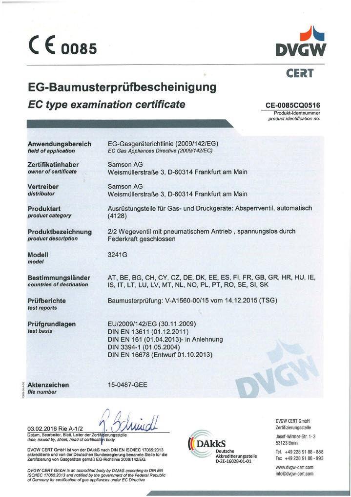
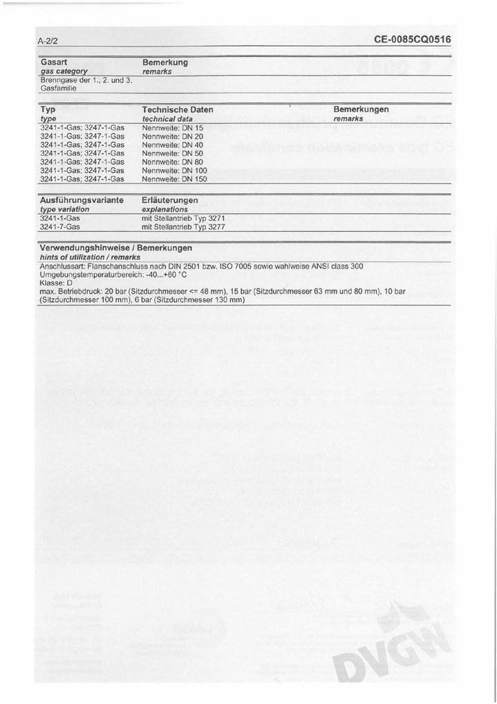
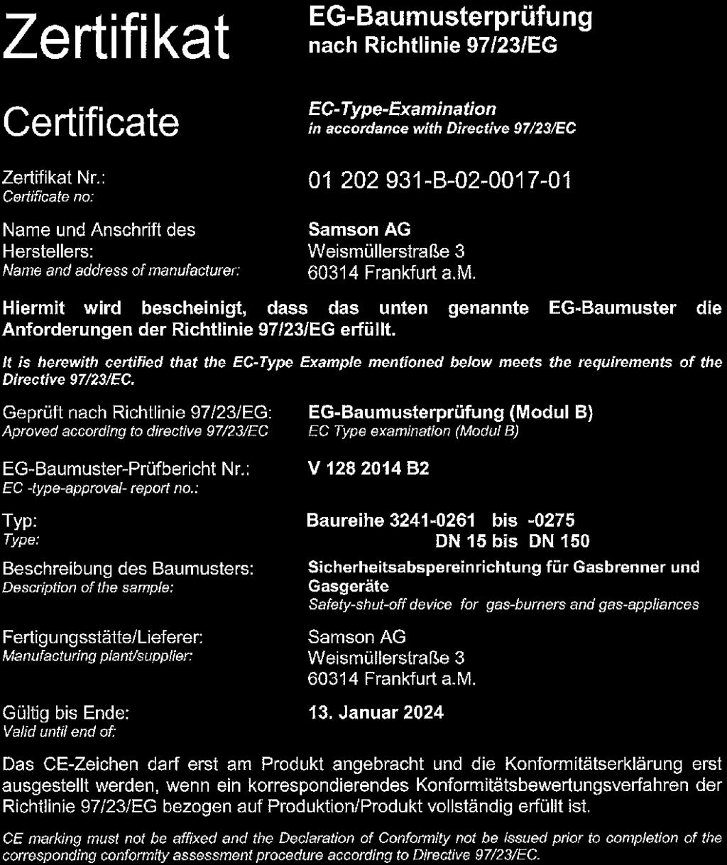
7 Safety instructions and measures Responsibilities of the operator The operator is responsible for proper operation and compliance with the safety regulations. Operators are obliged to provide these mounting and operating instructions as well as the referenced documents to the operating personnel and to instruct them in proper operation. Furthermore, the operator must ensure that operating personnel or third persons are not exposed to any danger. Responsibilities of operating personnel Operating personnel must read and understand these mounting and operating instructions as well as the referenced documents and observe the hazard statements, warning and caution notes specified in them. Furthermore, the operating personnel must be familiar with the applicable health, safety and accident prevention regulations and comply with them. Referenced standards and regulations The control valves comply with the requirements of the European Pressure Equipment Directive 2014/68/EU. Valves with a CE marking have a declaration of conformity, which includes information about the applied conformity assessment procedure. This declaration of conformity is included in the Appendix of these instructions (see section 10.2). Valve class D: the control valves meet the requirements of the European Gas Appliance Directive 2009/142/EC. The corresponding EC type examination certificate is the Appendix of these instructions (see section 10.2). Valve class E: the control valves meet the requirements of the 90/396/EEC. This type examination certificate is included in the Appendix of these instructions (see section 10.2). The control valves meet the safety, construction and function requirements for automatic shut-off valves with gas burners, gas equipment, and similar applications according to DIN EN
8 Safety instructions and measures Referenced documentation The following documents apply in addition to these mounting and operating instructions: Mounting and operating instructions for mounted actuator, e.g. u EB 8310 X for Type 3271 and Type 3277 Actuators Mounting and operating instructions for mounted valve accessories (positioner, solenoid valve etc.) u AB 0100 for tools, tightening torques, and lubricant 1.1 Notes on possible severe personal injury! DANGER Risk of bursting in pressure equipment. Control valves and pipelines are pressure equipment. Improper opening can lead to valve components bursting. Before starting any work on the control valve, depressurize all plant sections concerned as well as the valve. Drain the process medium from all the plant sections concerned as well as the valve. Wear personal protective equipment. 1.2 Notes on possible personal injury! WARNING Crush hazard arising from moving parts. The control valve contains moving parts (actuator and plug stems), which can injure hands or fingers if inserted into the valve. Do not insert hands or fingers into the yoke while the valve is in operation. While working on the control valve, disconnect and lock the pneumatic air supply as well as the control signal. 8
9 Safety instructions and measures! WARNING Risk of personal injury when the actuator vents. While the valve is operating, the actuator may vent during closed-loop control or when the valve opens or closes. Install the control valve in such a way that the actuator does not vent at eye level. Use suitable silencers and vent plugs. Wear eye protection when working in close proximity to the control valve. Risk of personal injury due to preloaded springs. Valves in combination with pneumatic actuators with preloaded springs are under tension. These control valves with SAMSON pneumatic actuators can be identified by the long bolts protruding from the bottom of the actuator. Before starting any work on the actuator, relieve the compression from the preloaded springs (see associated actuator documentation). Risk of personal injury due to residual process medium in the valve. While working on the valve, residual process medium can escape and, depending on its properties, may lead to personal injury, e.g. (chemical) burns. If possible, drain the process medium from all the plant sections concerned and the valve. Wear protective clothing, safety gloves, and eyewear. Risk of burn injuries due to hot or cold components and pipelines. Depending on the process medium, valve components, and pipelines may get very hot or cold and cause burn injuries. Allow components and pipelines to cool down or heat up. Wear protective clothing and safety gloves. 9
10 Safety instructions and measures 1.3 Notes on possible property damage! NOTICE Risk of valve damage due to contamination (e.g. solid particles) in the pipeline. The plant operator is responsible for cleaning the pipelines in the plant. Flush the pipelines before start-up. Observe the maximum permissible pressure for valve and plant. Risk of valve damage due to unsuitable medium properties. The valve is sized according to Directive 2009/142/EC (valve class D) or 90/396/ EEC (valve class E) for fuel gases. Only use the process medium specified for sizing the valve. Risk of leakage and valve damage due to excessively high or low tightening torques. Observe the specified torques on tightening control valve components. Excessively tightened torques lead to parts wearing out quicker. Parts that are too loose may cause leakage. Observe the specified tightening torques (u AB 0100). Risk of valve damage due to the use of unsuitable tools. Certain tools are required to work on the valve. Only use tools approved by SAMSON (u AB 0100). Risk of valve damage due to the use of unsuitable lubricants. The lubricants to be used depend on the valve material. Unsuitable lubricants may corrode and damage the valve surface. Only use lubricants approved by SAMSON (u AB 0100). 10
11 11
12 Markings on the control valve 2 Markings on the control valve 2.1 Nameplate for gas version Type Stellventil Control Valve Auftrags-Nr. Order No. N O de commande Vanne de réglage Meßstelle TAG No. Repère SAMSON AG Weismüllerstraße 3 D Frankfurt/M DN Material Kvs 6 PN 7 8 Cv 9 Characteristic 10 % 10 lin. 10 on-off Sitz/Kegel weich dichtend stellitiert Hub Isolierteil Mischventil Seat/Plug 11 soft seated 11 stellited 11 Travel 12 mm Insulating section 13 Mixing Valve 14 Siège/Clapet PTFE élanchéité stellité Course Pièce d isolement Vanne Mélangeuse Stopfbuchse 15 PTFE entlastet 16 PTFE Balg Strömungsteiler Verteilventil Stuffing box balanced Bellows 17 Flow divider 18 Diverting Valve 14 Presse-étoupe Graphite équilibré Graphite Soufflet Répartiteur de flux Vanne de Distribution Stellantrieb Feder schließt öffnet Max. Stelldruck 6 bar Actuator 19 cm² Spring closes 20 opens 20 Max. signal pressure 87 psi 21 Servo-moteur Ressort ferme ouvre Pression de commande max. Federbereich Stelldruckbereich Spring range 22 bar Signal pressure range 23 bar Δp max. = 24 bar p Gamme du ressort 2 = 0 Plage de pression de commande Betriebsdruck p 1 abs Betriebstemp. t 1 Medium Operating pressure 25 bar Operating temp. 26 C Fluid Pression de service Temp. de service Fluide Made in Germany Fig. 1: Nameplate for gas version 1 Type 2 Configuration ID 3 (empty) 4 Order number 5 Tag no. 6 Valve size: DIN: DN ANSI: NPS 7 Pressure rating: DIN: PN ANSI: CL 8 Material 9 Flow coefficient: DIN: K VS ANSI: C V 10 Characteristic: %: equal percentage lin: linear on-off: quick opening 11 Seat-plug seal: Material Stellite facing Soft seal with PTFE 12 Valve travel in mm 13 Insulating section 14 Mixing or diverting valve 15 Packing: PTFE Graphite 16 Pressure balancing: PTFE Graphite 17 Bellows material 18 Flow divider 19 Actuator area in cm² 20 Direction of action Fail-close Fail-open 21 Max. signal pressure in bar 22 Bench range in bar 23 Signal pressure range in bar 24 Max. differential pressure in bar 25 Operating pressure in bar 26 Operating temperature in C 27 Process medium 28 (empty) 12
13 Markings on the control valve 2.2 Valve nameplate SAMSON Fig. 2: Valve nameplate 1 5 PED (Pressure Equipment Directive), "Art. 4, Abs. 3" ID of the notified body, fluid group, and category 6 Type designation 8 Material 9 Year of manufacture 10 Valve size: DIN: DN ANSI: NPS 11 Pressure rating: DIN: PN ANSI: CL 12 Order no. with modification index For after-sales service orders: AA prefix 13 Position in order For after-sales service orders: configuration ID 14 Flow coefficient: DIN: K VS ANSI: C V 15 Characteristic: %: equal percentage Lin: linear NO/NC: quick opening 16 Seat-plug seal: ST: Stellite facing PT: soft seal with PTFE 17 Seat code (trim material) On request 19 Flow divider: 1: ST 1 20 Country of origin 2.3 Actuator nameplate See associated actuator documentation. 13

14 Markings on the control valve 2.4 Other markings DVGW register number A Typ 3241-G 0085 DVGW-PIN Klasse D, p zul. Zul. Außentemp C Fig. 3: DVGW register number Material number The seat and plug of the valves have an article number written on them. Specifying this article number, you can contact us to find out which material is used. Additionally, a seat code is used to identify the trim material. This seat code is specified on the nameplate (17 on nameplate). For more details on the nameplate, see section Position of marking The nameplate for the gas version (210) is affixed to the actuator. The valve nameplate (80) is affixed to the flange. The actuator nameplate (A100) is stuck on the diaphragm casing (Fig. 4). The plate with the DVGW register number (212) is affixed to the bellows seal. Fig. 4: Markings on the control valve 14
15 15
16 Design and principle of operation 3 Design and principle of operation The single-seated Type 3241G Globe Valve is combined with a SAMSON Type 3271 or Type 3277 Pneumatic Actuator, solenoid valve, and strainer (see Fig. 5). Optionally, a positioner can be used. The seat (4) and plug with plug stem (5) are installed in the body (1). The plug stem is screwed to the plug stem with bellows seal (37). The plug stem is sealed by the metal bellows and the packing (15). The stem connector clamps (A26/27) connect the actuator stem (A7) of the mounted actuator. The bellows seal (22) is fitted with a test connection (42). It can be used to monitor the sealing ability of the bellows. A strainer installed upstream of the valve body. It prevents solid particles in the process medium from damaging the valve. The strainer is not required when a central strainer facility is installed. plug to move. The actuator size is determined by the diaphragm area. The process medium flows through the strainer and the valve in the direction indicated by the arrow. A rise in signal pressure causes the force acting on the diaphragm in the actuator to increase. The springs are compressed. Depending on the selected direction of action, the actuator stem retracts or extends. As a result, the plug position in the seat changes and determines the flow rate through the valve. The signal pressure p st is applied to the pilot valve whose coil is connected to the safety interlock circuit (switch 14, Fig. 6 and Fig. 7). During operation, the coil is energized and the signal pressure p st acts on the diaphragm. In the event of a malfunction, the pilot valve is activated and the pressure acting on the diaphragm is relieved, causing the control valve to quickly close. Note For special versions made of A216 WCC or A351 CF8M in Class 300: as a DIN version of the Type 2 NI Strainer is only available, a central strainer facility must be installed when an ANSI version is used. The springs in the pneumatic actuator are located either above or below the diaphragm depending on the selected fail-safe action (see section 3.1). A change in the signal pressure acting on the diaphragm causes the 16
17 Design and principle of operation A7 A26/ Pilot valve 8 P st Strainer Body 2 Flange 4 Seat 5 Plug (with plug stem) 8 Threaded bushing (packing nut) 9 Stem connector nut 10 Lock nut 14 Body nut 15 Packing 17 Body gasket 22 Bellows seal 37 Plug stem with metal bellows 42 Test connection A7 Actuator stem A26/27 Stem connector clamps Fig. 5: Type Gas Automatic Shut-off Valve 17
18 Design and principle of operation Voltage P st 14 Fig. 6: Functional diagram showing version without positioner 11 Pilot valve 13 Positioner 14 Switch for safety interlock circuit 2 11 Voltage P st 13 Fig. 7: Functional diagram showing version with positioner 18
19 Design and principle of operation 3.1 Fail-safe positions The fail-safe position depends on the mounted actuator. Depending on how the compression springs are arranged in the pneumatic actuator, the valve has two different fail-safe positions: Actuator stem extends (FA) When the signal pressure is reduced or the air supply fails, the springs move the actuator stem downward and close the valve. The valve opens when the signal pressure is increased enough to overcome the force exerted by the springs. Actuator stem retracts (FE) When the signal pressure is reduced or the air supply fails, the springs move the actuator stem upwards and open the valve. The valve closes when the signal pressure is increased enough to overcome the force exerted by the springs. 3.2 Versions Actuators To select a suitable actuator, see Table 6 (valve class D) or Table 9 (valve class E). 3.3 Technical data The nameplate provide information on the control valve version (see section 2.1) Common technical data DIN DVGW test mark The valves were typetested by TÜV (German technical surveillance association) and received the test mark by DVGW (German Technical and Scientific Association for Gas and Water) as specified in Table 5 or Table 8. Compliance The Type 3241G Valve bears both the CE and EAC marks of conformity. Note The "stem retracts" direction of action is only permitted for a certain version designated for valve class E. See Table 9. Leakage class Leakage class according to DIN EN
20 Design and principle of operation Noise emission SAMSON is unable to make general statements about noise emission as it depends on the valve version, plant facilities, and process medium. On request, SAMSON can perform calculations according to IEC 60534, Part 8-3 and Part 8-4 or VDMA (edition 89).! WARNING Risk of hearing loss or deafness due to loud noise. Wear hearing protection when working near the valve. Table 1: Materials (material numbers according to DIN EN) Valve Body 1) DN 15 to 150 (NPS ½ to 6) Cast steel Cast stainless steel Forged steel DN 15 to 80 Forged stainless steel Valve bonnet Seat and plug Plug with soft seal, PTFE seal with 15 % glass fiber Guide bushing Packing V-ring packing: PTFE with carbon Spring: Intermediate piece Metal bellows Body gaskets Graphite on metal core Cast steel Strainer Cast stainless steel Standard strainer insert and dual strainer insert ) Special version: A216 WCC or A351 CF8M in Class 300. As a DIN version of the Type 2 NI Strainer is only available, a central strainer facility must be installed. 20
21 Design and principle of operation Dimensions and weights Table 2 to Table 4 provide a summary of the dimensions and weights of the standard version of Type 3241 Valve. Dimensions in mm Weights in kg Table 2: Dimensions for Type 3241G Valve Valve DN ) 150 1) Length L mm Length L1 mm Height H1 with 175, 355, and 750 cm² actuator area mm H2 Cast steel mm Forged steel mm ) Only with valve body made of or Table 3: Dimensions for Types 3271 and 3277 Pneumatic Actuators Actuator area cm² Diaphragm ØD mm H 1) mm H3 2) mm H5 Type 3277 mm Thread Type 3271 M30 x 1.5 Type 3277 M30 x 1.5 a Type 3271 G ¼ (¼ NPT) G ¼ (¼ NPT) G 3 /8 ( 3 /8 NPT) G 3 /8 ( 3 /8 NPT) G 3 /8 ( 3 /8 NPT) G 3 /8 ( 3 /8 NPT) a2 Type 3277 G 3 /8 G 3 /8 G 3 /8 G 3 /8 G 3 /8 G 3 /8 1) Height with welded-on lifting eyelet or height of eyebolt according to DIN 580. Height of the swivel lifting hook may differ. Actuators up to 355 cm² without lifting eyelet 2) Minimum clearance to remove actuator due to solenoid valve and bracket 21
22 Design and principle of operation Table 4: Weights Valve DN Weight without actuator kg (approx.) Strainer Weight kg (approx.) Actuator cm² Weight of Type 3271 kg (approx.) Weight of Type 3277 kg (approx.) Solenoid valve kg (approx.) 1 Dimensional drawings ØD a H2 H1 H H3 ØD a a2 H2 H1 H5 H H3 L1 L Type Gas L1 Type Gas L 22
23 Design and principle of operation Technical data of version for valve class D Table 5: Type 3241G Valve Cast body: DN 15 to 150 Forged body: DN 15 to 80 DIN DVGW test mark CE-0085CQ0516 Nominal size DN Nom. pressure PN 40 K VS coefficient (without flow divider ) K VS I (with flow divider 1) Seat diameter mm Perm. diff./ operating pressure bar Rated travel mm Rangeability 50:1 30:1 Perm. ambient temperature 40 to +60 C Perm. medium temperature 20 to +220 C Closing time <5 s 1) Valve class Valve class D Strainer Type 2 NI, special version for gas, 0.25 mm mesh size 1) Closing time <1 s when fitted with correspondingly sized pilot valves (possibly in combination with a quick exhaust valve) Table 6: Types 3271 and 3277 Pneumatic Actuators Actuator area in cm² Signal pressure range Required supply pressure bar 0.8 to to to to to 2.65 bar Max. supply pressure bar Closing force kn Fail-safe position Fail-close 23
24 Design and principle of operation Table 7: Pilot valves for Type Gas Valid for closing time <5 s Nominal size DN Control valve Actuator area [cm²] Fail-safe position Solenoid valve manufacturer and model number SAMSOMATIC model K VS coefficient (Attachment: threaded connection) 3963-xxxxx xxxxx Norgren series Herion (Attachment: NAMUR interface) ) Stem 355 extends (FA) 355 Fail-close ) Herion Type Solenoid valve with quick exhaust module 24
25 Design and principle of operation Technical data of version for valve class E Table 8: Type 3241G Valve Cast body: DN 15 to 150 Forged body: DN 15 to 80 DIN DVGW test CE-0085AQ mark 1) Nom. size DN ) Nominal PN 40 pressure K VS coefficient (without flow divider 1) K VS I (with flow divider 1) Seat diameter mm Perm. diff./ operating pressure bar Rated travel mm Rangeability 50:1 30:1 50:1 Perm. ambient temperature 40 to +60 C Perm. medium temperature 20 to +220 C Closing time <1 s Valve class Valve class E Valve group 2, class 2 Strainer Type 2 NI, special version for gas, 0.25 mm mesh size 1) Test mark: CE 0085AQ 0734 for special version with "fail-open" fail-safe action 25
26 Design and principle of operation Table 9: Types 3271 and 3277 Pneumatic Actuators Actuator area in cm² Signal pressure bar range Required supply pressure Max. supply pressure Closing force Fail-safe position 0.4 to to to to to to to to to to to to to to bar bar kn Fail-close 0.4 to 2.0 Failopen Table 10: Pilot valves for Type Gas Valve Type 3241 DN Actuator Fail-safe position Solenoid valve manufacturer and model number SAMSOMATIC model K VS coefficient (Attachment: threaded connection) 3963-xxxxx xxxxx Norgren series Herion (Attachment: NAMUR interface) ) Stem extends (FA) Fail-close Stem retracts (FE) Fail-open 1) Herion Type Solenoid valve with quick exhaust module 26
27 Measures for preparation 4 Measures for preparation After receiving the shipment, proceed as follows: 1. Check the scope of delivery. Compare the shipment received against the delivery note. 2. Check the shipment for transportation damage. Report any damage to SAMSON and the forwarding agent (refer to delivery note). 4.1 Unpacking Note Do not remove the packaging until immediately before installing the valve into the pipeline. Proceed as follows to lift and install the valve: 1. Remove the packaging from the valve. 2. Dispose of the packaging in accordance with the valid regulations. 4.2 Transporting and lifting! DANGER Hazard due to suspended loads falling. Stay clear of suspended or moving loads.! WARNING Risk of lifting equipment tipping and risk of damage to lifting accessories due to exceeding the rated lifting capacity. Only use approved lifting equipment and accessories whose minimum lifting capacity is higher than the weight of the valve (including actuator, if applicable). Refer to section 3.3 for weights.! WARNING Risk of personal injury due to control valve tipping. Observe the valve's center of gravity. Secure the valve against tipping over or turning.! NOTICE Risk of valve damage due to foreign particles entering the valve. The protective caps fitted on the valve's inlet and outlet prevent foreign particles from entering the valve and damaging it. Do not remove the protective caps until immediately before installing the valve into the pipeline. 27
28 Measures for preparation! NOTICE Risk of valve damage due to incorrectly attached slings. The welded-on lifting eyelet on SAMSON actuators is only intended for mounting and removing the actuator as well as lifting the actuator without valve. Do not use this lifting eyelet to lift the entire control valve assembly. When lifting the control valve, make sure that the slings attached to the valve body bear the entire load. Do not attach load-bearing slings to the actuator or any other parts. Observe lifting instructions (see section 4.2.2). Tip SAMSON's After-sales Service department can provide more detailed transport and lifting instructions on request Transporting The control valve can be transported using lifting equipment (e.g. crane or forklift). Leave the control valve in its transport container or on the pallet to transport it. Observe the transport instructions. Transport instructions Protect the control valve against external influences (e.g. impact). Do not damage the corrosion protection (paint, surface coatings). Repair any damage immediately. Protect the control valve against moisture and dirt. The permissible transportation temperature of standard control valves is 20 to +65 C. Note Contact SAMSON's After-sales Service department for the transportation temperatures of other valve versions Lifting To install a large valve into the pipeline, use lifting equipment (e.g. crane or forklift) to lift it. Lifting instructions Secure slings against slipping. Make sure the slings can be removed from the valve once it has been installed into the pipeline. 28
29 Measures for preparation Prevent the control valve from tilting or tipping. Do not leave loads suspended when interrupting work for longer periods of time. Make sure that the axis of the pipeline is always horizontal during lifting and the axis of the plug stem is always vertical. Make sure that the additional sling between the lifting eyelet and rigging equipment (hook, shackle etc.) does not bear any load when lifting actuators with an actuator area of 700 cm² or larger. The sling only protects the control valve from tilting while being lifted. Before lifting the control valve, tighten the sling. Make sure that the sling around the strainer is long enough and that the load that it bears is not too heavy. The sling must not bend the strainer upwards and not place strain on the flanged joint. Attach one sling to each flange of the body and to the rigging equipment (e.g. hook) of the crane or forklift (see Fig. 8) cm² and larger: attach another sling to the lifting eyelet on the actuator and to the rigging equipment. 4. Attach another sling to the flange of the strainer. 5. Carefully lift the control valve. Check whether the lifting equipment and accessories can bear the weight. Fig. 8: Lifting points on the control valve 29
30 Measures for preparation 6. Move the control valve at an even pace to the site of installation. 7. Install the valve into the pipeline (see section 5.2.3). 8. After installation in the pipeline, check whether the flanges are bolted tight and the valve in the pipeline holds. 9. Remove slings. Tip We recommend using a hook with safety latch (see Fig. 8). The safety latch prevents the slings from slipping during lifting and transporting. 4.3 Storage! NOTICE Risk of valve damage due to improper storage. Observe storage instructions. Avoid long storage times. Contact SAMSON in case of different storage conditions or long storage periods. Note We recommend regularly checking the control valve and the prevailing storage conditions during long storage periods. Storage instructions Protect the control valve against external influences (e.g. impact). Do not damage the corrosion protection (paint, surface coatings). Repair any damage immediately. Protect the control valve against moisture and dirt. Store it at a relative humidity of less than 75 %. In damp spaces, prevent condensation. If necessary, use a drying agent or heating. Make sure that the ambient air is free of acids or other corrosive media. The permissible storage temperature of standard control valves is 20 to +65 C. Note Contact SAMSON's After-sales Service department for the storage temperatures of other valve versions. Do not place any objects on the control valve. Special storage instructions for elastomers Elastomer, e.g. actuator diaphragm To keep elastomers in shape and to prevent cracking, do not bend them or hang them up. We recommend a storage temperature of 15 C for elastomers. Store elastomers away from lubricants, chemicals, solutions, and fuels. Tip SAMSON's After-sales Service department can provide more detailed storage instructions on request. 30
31 Measures for preparation 4.4 Preparation for installation Proceed as follows: Flush the pipelines. Note The plant operator is responsible for cleaning the pipelines in the plant. Check the valve to make sure it is clean. Check the valve for damage. Check to make sure that the type designation, valve size, material, pressure rating, and temperature range of the valve match the plant conditions (size and pressure rating of the pipeline, medium temperature etc.). Check any mounted pressure gauges to make sure they function. When the valve and actuator are already assembled, check the tightening torques of the bolted joints (u AB 0100). Components may loosen during transport. 31
32 Mounting and start-up 5 Mounting and start-up SAMSON valves are delivered ready for use. The procedure to mount and start up the valve are described in the following.! NOTICE Risk of valve damage due to excessively high or low tightening torques. Observe the specified torques on tightening control valve components. Excessively tightened torques lead to parts wearing out quicker. Parts that are too loose may cause leakage. Observe the specified tightening torques (u AB 0100).! NOTICE Risk of valve damage due to the use of unsuitable tools. Only use tools approved by SAMSON (u AB 0100). 5.1 Mounting the actuator onto the valve Valve and actuator are delivered ready mounted. 5.2 Installing the valve into the pipeline Checking the installation conditions Pipeline routing The inlet and outlet lengths vary depending on the process medium. To ensure the control valve functions properly, follow the installation instructions given below: Observe the inlet and outlet lengths (see Table 11). Contact SAMSON if the valve conditions or state of the medium process deviate. Install the valve free of stress and with the least amount of vibrations as possible. If necessary, attach supports to the valve. Install the valve allowing sufficient space to remove the actuator and valve or to perform service and repair work on them. Mounting position Generally, we recommend installing the valve with the actuator upright and on top of the valve. Contact SAMSON if the mounting position is not as specified above. Support or suspension Depending on the valve version and mounting position, the control valve and pipeline must be supported or suspended. The plant engineering company is responsible in this case. 32
33 Mounting and start-up Table 11: Inlet and outlet lengths Q Q a b Flow rate Inlet length Outlet length a x DN b x DN State of process medium Gas Valve conditions Inlet length a Outlet length b Ma Ma ! NOTICE Premature wear and leakage due to insufficient support or suspension. In the following versions, the control valve must be supported or suspended: Valves that are not installed with the actuator in the upright position on top of the valve. Attach a suitable support or suspension to the valve. Vent plug Vent plugs are screwed into the exhaust air ports of pneumatic devices. They ensure that any exhaust air that forms can be vented to the atmosphere (to avoid excess pressure in the device). Furthermore, the vent plugs allow air intake to prevent a vacuum from forming in the device. Locate the vent plug on the opposite side to the workplace of operating personnel. On mounting valve accessories, make sure that they can be operated from the workplace of the operating personnel. Note The workplace of operating personnel is the location from which the valve, actuator, and any mounted valve accessories can be accessed to operate them Additional fittings Insulation Only insulate control valves with bellows seal up to the bonnet flange of the valve body for medium temperatures below 0 C and above 220 C. Test connection Versions with bellows seal fitted with a test connection (G 1 / 8) at the top flange allow the sealing ability of the bellows to be monitored. 33
34 Mounting and start-up! WARNING Risk of personal injury due to pressurized components and process medium escaping under pressure. Do not loosen the screw of the test connection while the valve is in operation. Noise emission Trims with flow dividers can be used to reduce noise emission (see u T 8081) Installing the control valve 1. Depressurize the plant. 2. Remove the protective caps from the valve ports before installing the valve. 3. Lift the valve using suitable lifting equipment to the site of installation (see section 4.2.2). Observe the flow direction through the valve. The arrow on the valve indicates the direction of flow. 4. Make sure that the correct flange gaskets are used. 5. Bolt the pipe to the valve free of stress. 6. Depending on the field of application, allow the valve to cool down or heat up to reach ambient temperature before start up. 7. Make sure that the vent of the pilot valve and the pressure connection on the top case of the actuator are open. 8. Check the valve to ensure it functions properly. 5.3 Quick check SAMSON valves are delivered ready for use. To test the valve's ability to function, the following quick checks can be performed: Leak testing Perform the leak testing as described in section 7.5. Travel motion The movement of the actuator stem must be linear and smooth. Open and close the valve, observing the movement of the actuator stem. Apply the maximum and minimum control signals to check the end positions of the valve. Check the travel reading at the travel indicator scale. Fail-safe position Shut off the signal pressure line. Check whether the valve moves to the fail-safe position. Pressure test During the pressure test, make sure the following conditions are met: Retract the plug stem to open the valve. Observe the maximum permissible pressure for valve and plant. 34
35 Mounting and start-up Note The plant operator is responsible for performing the pressure test. SAMSON's After-sales Service department can support you to plan and perform a pressure test for your plant. 35
36 Operation 6 Operation Immediately after completing mounting and start-up (see section 5), the valve is ready for use.! WARNING Crush hazard arising from moving parts (actuator and plug stem). Do not insert hands or fingers into the yoke while the valve is in operation.! WARNING Risk of personal injury when the actuator vents. Wear eye protection when working in close proximity to the control valve.! WARNING Risk of burn injuries due to hot or cold components and pipelines. Depending on the process medium, valve components, and pipelines may get very hot or cold and cause burn injuries. Wear protective clothing and safety gloves.! NOTICE Operation disturbed by a blocked actuator or plug stem. Do not impede the movement of the actuator or plug stem by inserting objects into their path. 36
37 Servicing 7 Servicing The control valve is subject to normal wear, especially at the seat, plug, and packing. Depending on the operating conditions, check the valve at regular intervals to prevent possible failure before it can occur. SAMSON's After-sales Service department can support you to draw up an inspection plan for your plant. We recommend removing the valve from the pipeline for service or repair work (see section 9.2).! Tip DANGER Risk of bursting in pressure equipment. Control valves and pipelines are pressure equipment. Improper opening can lead to bursting of the valve. Before starting any work on the control valve, depressurize all plant sections concerned as well as the valve. Drain the process medium from all the plant sections concerned as well as the valve. Wear personal protective equipment.! WARNING Risk of personal injury due to residual process medium in the valve. While working on the valve, residual process medium can escape and, depending on its properties, may lead to personal injury, e.g. (chemical) burns. Wear protective clothing, safety gloves, and eyewear.! WARNING Risk of burn injuries due to hot or cold components and pipeline. Valve components and the pipeline may become very hot or cold. Risk of burn injuries. Allow components and pipelines to cool down or heat up. Wear protective clothing and safety gloves.! NOTICE Risk of valve damage due to incorrect servicing or repair. Service and repair work must only be performed by trained staff.! NOTICE Risk of valve damage due to excessively high or low tightening torques. Observe the specified torques on tightening control valve components. Excessively tightened torques lead to parts wearing out quicker. Parts that are too loose may cause leakage. Observe the specified tightening torques (u AB 0100). 37
38 Servicing! Risk of valve damage due to the use of unsuitable tools. Only use tools approved by SAMSON (u AB 0100).! NOTICE NOTICE Risk of valve damage due to the use of unsuitable lubricants. Only use lubricants approved by SAMSON (u AB 0100). Note The control valve was checked by SAMSON before it left the factory. Certain test results (seat leakage and leak test) certified by SAMSON lose their validity when the valve body or actuator housing is opened. After completing servicing work, the gastight shut-off of the valve must be tested. This test must be performed by fully trained, qualified operating personnel. The product warranty becomes void if service or repair work not described in these instructions is performed without prior agreement by SAMSON's After-sales Service department. Only use original spare parts by SAMSON, which comply with the original specifications. 7.1 Replacing the gasket 1. Remove the actuator from the valve. See associated actuator documentation. 2. Unscrew the body nuts (14) gradually in a criss-cross pattern. 3. Lift the bellows seal (22) with valve bonnet (2) and plug with plug stem (5) off the body (1). 4. Remove the gasket (17). Carefully clean the sealing faces in the valve body (1) and on the bellows seal (22). 5. Insert a new gasket (17) into the body. 6. Place the bellows seal (22) with valve bonnet (2) and plug with plug stem (5) onto the body. Version with V-port plug: place the assembly onto the valve body, making sure that the largest V-shaped port of the V-port plug faces toward the valve outlet. See section Firmly press the plug (5) into the seat (4). Fasten down the bellows seal (22) with the body nuts (14). Tighten the nuts gradually in a criss-cross pattern. Observe tightening torques. 8. Mount actuator. See associated actuator documentation. 9. Adjust lower or upper signal bench range. See associated actuator documentation. 10. Check the control valve. See section
39 Servicing Strainer A7 A26/ P st Pilot valve Body 2 Flange 4 Seat 5 Plug (with plug stem) 8 Threaded bushing (packing nut) 9 Stem connector nut 10 Lock nut 14 Body nut 15 Packing 17 Body gasket 22 Bellows seal 37 Plug stem with metal bellows 42 Test connection A7 Actuator stem A26/27 Stem connector clamps 1 Fig. 9: Type Gas Automatic Shut-off Valve 7.2 Other service work! NOTICE Risk of control valve damage due to incorrect service or repair. To replace seat and plug, packing or bellows seal, contact SAMSON's After-sales Service department. 7.3 Aligning the V-port plug Each V-port plug has three V-shaped ports. Depending on the valve size, the size of the symmetrically arranged V-shaped ports varies. The process medium in the valve flows through the V-shaped ports as soon as the plug is lifted out of the seat (i.e. the valve opens). 1. Before mounting the actuator, determine which V-shaped port is uncovered first when the plug is lifted out of the seat. 39
40 Servicing Tip Usually, this is the largest V-shaped port. 2. On mounting the actuator, make sure that the V-shaped port uncovered first faces toward the valve outlet.! NOTICE Risk of damage to the wall of the valve body due to incorrectly diverted jet stream. The process medium cannot flow unobstructed through the valve when the V-port plug has been installed incorrectly. This will result in the process medium hitting the body wall, which may lead to severe valve damage. Make sure the V-port plug is installed correctly. 7.4 Cleaning the strainer See associated device documentation. 7.5 Testing the control valve After completing servicing work, the gastight shut-off of the valve must be tested, for example. The tests must be documented. The following tests are required (see Table 12): Seat leakage testing Leak test Function testing Tip SAMSON's After-sales Service department can support you to perform the required tests. 7.6 Preparation for return shipment Defective valves can be returned to SAMSON for repair. Proceed as follows to return valves to SAMSON: 1. Put the control valve out of operation (see section 9). 2. Decontaminate the valve. Remove any residual process medium. 3. Fill in the Declaration on Contamination, which can be downloaded from our website at u > Services > Check lists for after sales service > Declaration on Contamination. 4. Send the valve together with the filled-in form to your nearest SAMSON subsidiary. SAMSON subsidiaries are listed on our website at u > Contact. 7.7 Ordering spare parts and operating supplies Contact your nearest SAMSON subsidiary or the SAMSON After-sales Service department for information on spare parts, lubricants, and tools. 40
41 Servicing Table 12: Required tests Seat leakage testing Standard IEC or ANSI/FCI 70-2 Test medium Test pressure Use dry compressed air free of oil and grease Inlet: 4 bar (standard); max. 40 bar Outlet: atmospheric pressure or connection to a flow meter 1. Move the plug out of the seat (valve closed). 2. Apply the test medium at the test pressure to the inlet side. Test procedure 3. As soon as the leakage rate is constant, measure the seat leakage. Make sure the measured seat leakage does not exceed the maximum permissible leakage rate specified for the associated leakage class. Leak test Standard Test similar to DIN EN , test P11 Test medium Use dry compressed air free of oil and grease Test pressure 5 bar (standard) Test time See DIN EN Clamp the valve into the test fixture or fit it with a test adapter. 2. Move the plug out of the seat (valve open). 3. Apply the test pressure to the valve and hold the pressure for the specified test duration. 4. Perform the leak test visually using leak detection spray or immerse the valve Test procedure in a water bath. No bubbles must become visible during the test period. 5. Leak-test the bellows. For example, connect a hose to the test connection and immerse the end of the hose into a water bath. No bubbles must become visible during the test period. 6. After the test duration has elapsed, reduce the test pressure to atmospheric pressure. Functional test: testing the rated travel Measures for preparation The actuator is mounted properly. Valve accessories (positioner, solenoid valve etc.) are mounted properly. The packing is tightened correctly. No pressure prevails inside the valve. Test procedure 1. Apply the input signal to move the valve to the end positions. 2. Determine the rated travel using the travel indicator scale. 41
42 Servicing Spare parts See section 10.3 for details on spare parts. Lubricant Details on suitable lubricants can be found in the document u AB Tools Details on suitable tools can be found in the document u AB
43 43
44 Malfunctions 8 Malfunctions Depending on the operating conditions, check the valve at certain intervals to prevent possible failure before it can occur. Operators are responsible for drawing up an inspection plan. Tip SAMSON's After-sales Service department can support you to draw up an inspection plan for your plant. 8.1 Troubleshooting Malfunction Possible reasons Recommended action Actuator or plug stem does not move on demand. Actuator is blocked. Check attachment. Unblock the actuator. Signal pressure too low Check the signal pressure. Check the signal pressure line for leakage. Actuator or plug stem does not move through the whole range. The valve leaks to the atmosphere (fugitive emissions). Increased flow through closed valve (seat leakage) Signal pressure too low The packing and metal bellows are defective. Metal bellows is defective. Flange joint loose or gasket worn out. Dirt or other foreign particles deposited between the seat and plug. Valve trim is worn. Check the signal pressure. Check the signal pressure line for leakage. Contact SAMSON's After-sales Service department. Contact SAMSON's After-sales Service department. Check the flange joint. Replace gasket at the flanged joint (see section 7.1 or contact SAMSON's After-sales Service department). Shut off the section of the pipeline and flush the valve. Contact SAMSON's After-sales Service department. Reduced flow rate Strainer blocked Clean strainer. See associated device documentation. 44
45 Malfunctions Note Contact SAMSON's After-sales Service department for malfunctions not listed in the table. 8.2 Emergency action Upon supply air or control signal failure, the valve moves to its fail-safe position (see section 3.1). The plant operator is responsible for emergency action to be taken in the plant. In the event of a valve malfunction: 1. Depressurize the plant. 2. Check the valve for damage. If necessary, contact SAMSON's Aftersales Service department. 45
46 Decommissioning and disassembly 9 Decommissioning and disassembly! DANGER Risk of bursting in pressure equipment. Control valves and pipelines are pressure equipment. Improper opening can lead to bursting of the valve. Before starting any work on the control valve, depressurize all plant sections concerned as well as the valve. Drain the process medium from all the plant sections concerned as well as the valve. Wear personal protective equipment.! WARNING Risk of personal injury due to residual process medium in the valve. While working on the valve, residual process medium can escape and, depending on its properties, may lead to personal injury, e.g. (chemical) burns. Wear protective clothing, safety gloves, and eyewear.! WARNING Risk of burn injuries due to hot or cold components and pipeline. Valve components and the pipeline may become very hot or cold. Risk of burn injuries. Allow components and pipelines to cool down or heat up. Wear protective clothing and safety gloves. 9.1 Decommissioning To decommission the control valve for service and repair work or disassembly, proceed as follows: 1. Depressurize the plant. 2. Completely drain the pipelines and valve. 3. Disconnect and lock the pneumatic air supply to depressurize the actuator. 4. If necessary, allow the pipeline and valve components to cool down or heat up. 9.2 Removing the valve from the pipeline 1. Put the control valve out of operation (see section 9.1). 2. Unbolt the flange joint. 3. Remove the valve from the pipeline (see section 4.2). 9.3 Removing the actuator from the valve See associated actuator documentation. 9.4 Disposal Observe local, national, and international refuse regulations. Do not dispose of components, lubricants, and hazardous substances together with your other household waste. 46
47 47
48 Appendix 10 Appendix 10.1 After-sales service Contact SAMSON's After-sales Service department for support concerning service or repair work or when malfunctions or defects arise Certificates The declarations of conformity and the type examination certificates are provided on the next pages. You can reach the After-sales Service Department at Addresses of SAMSON AG and its subsidiaries The addresses of SAMSON AG, its subsidiaries, representatives, and service facilities worldwide can be found on the SAMSON website, in all SAMSON product catalogs or on the back of these Mounting and Operating Instructions. Required specifications Please submit the following details: Order number and position number in the order Type, model number, nominal size, and valve version Pressure and temperature of the process medium Flow rate in kg/h or Nm³/h Bench range of the actuator (e.g. 0.2 to 1 bar) Installation drawing 48
49 SAMSON erklärt in alleiniger Verantwortung für folgende Produkte: Stellventil Typ Gas (mit pneumatischem Antrieb Typ 3271) Stellventil Typ Gas (mit pneumatischem Antrieb Typ 3277) die Konformität mit nachfolgender Anforderung: Verordnung des Europäischen Parlaments und des Rates über Geräte zur Verbrennung gasförmiger Brennstoffe und zur Aufhebung der Richtlinie 2009/142/EG (EU) 2016/426 vom 9. März 2016 Produktart Produktbezeichnung Ausrüstungsteile für Gas- und Druckgeräte Absperrventil, automatisch, Klasse D 2/2 Wegeventil mit pneumatischem Antrieb, spannungslos durch Federkraft geschlossen Prüfgrundlagen (EU) 2016/426 EN DIN DIN EN 161 DIN EN EG-Richtlinie 2009/142/EG Prüfberichte EG-Baumusterprüfbescheinigung CE-0085CQ0516 vom DVGW CERT GmbH Hersteller SAMSON AG Weismüllerstraße Frankfurt am Main, Germany Frankfurt am Main, Klaus Hörschken Zentralabteilungsleiter Entwicklung Ventile und Antriebe Dr. Michael Heß Zentralabteilungsleiter Product Management & Technical Sales Classification: Public SAMSON AKTIENGESELLSCHAFT Weismüllerstraße Frankfurt am Main Telefon: Telefax: samson@samson.de Revision 00 49
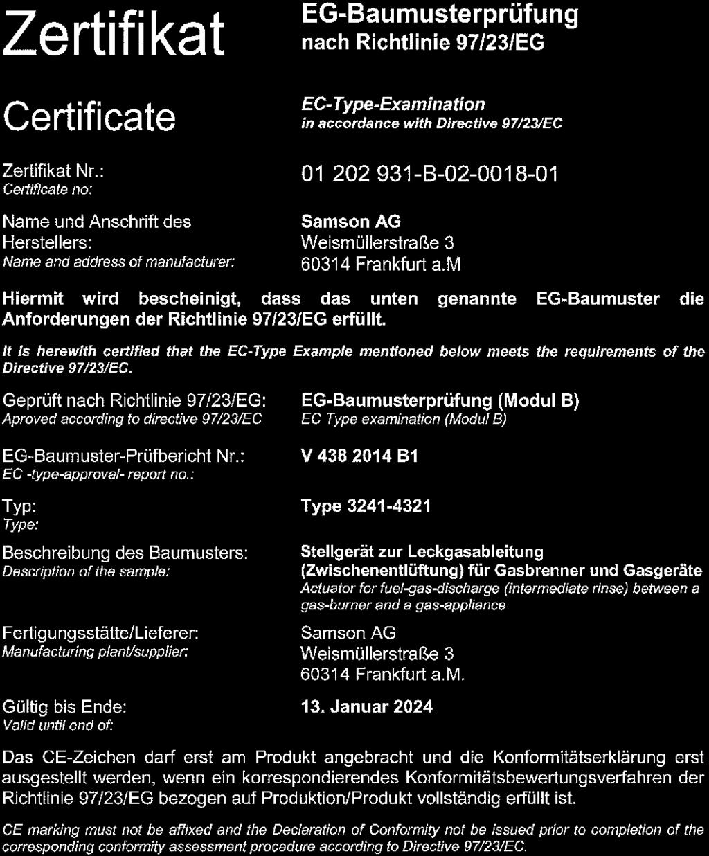
50 Modul/Module D / N CE-PED-D-SAM DEU SAMSON erklärt in alleiniger Verantwortung für folgende Produkte/explaines in sole resposibility for the following products: Geräte/Devices Bauart/Series Typ/Type Ausführung/Version Stellgerät für Heißwasser und Dampf mit Sicherheitsfunktion/Safety Accessories for Hot Water and Steam Sicherheitsabsperreinrichtung für Feuerungsanlagen/ Safety Accessories for Firing Plants Stellgerät für Heißwasser und Dampf mit Sicherheitsfunktion/ Safety Accessories for Hot Water and Steam Stellgerät für Wasser und Dampf mit Sicherheitsfunktion/ Safety Accessories for Water and Steam Sicherheitsabsperreinrichtung für Gasbrenner und Gasgeräte/Safety Accessories for Gas-burners and Gas- Equipment Stellgerät zur Leckgasableitung für Gasbrenner und Gasgeräte/Control Valve for draining for Gas-burners and Gas-equipm (2000 N) , , , , (1800 N) 3274 (3000 N) 3222, 3213, 2488, 2489, 2487, 2491, , 2495, 2423, mit Typ/with Type No. 2811, 2814, 2823, 3321, 3241, 3267 Zertifikat-Nr./Certificate No.: B , Zertifikat-Nr./Certificate No.: B , Zertifikat-Nr./Certificate No.: B mit/with 3271, Zertifikat-Nr./Certificate No.: B mit/with 3271 und/and 3277, 240cm² Zertifikat-Nr./Certificate No.: B mit/with 3271 und/and 3277, 350cm² Zertifikat-Nr./Certificate No.: B auch druckentlastet/also pressure relieved mit/with 3271 und/and 3277 Zertifikat-Nr./Certificate No.: B mit/with 3241, 2423, 2823, 3267 Zertifikat-Nr./Certificate No.: B mit/with 3241, 3214, 2814 Zertifikat-Nr./Certificate No.: B mit/with 3267, 2814, 2823, 2710, 2730 Zertifikat-Nr./Certificate No.: B bis/to Zertifikat-Nr./Certificate No.: B Zertifikat-Nr./Certificate No.: B die Konformität mit nachfolgender Anforderung/we declare conformity with the demands of the: Richtlinie des Europäischen Parlaments und des Rates zur Harmonisierung der Rechtsvorschriften der Mitgliedstaaten über die Bereitstellung von Druckgeräten auf dem Markt/Directive of the European Parliament and oft the Council on the harmonisation of the 2014/68/EU laws of the Member States relating to the making available on the market of pressure equipmentsiehe auch Artikel 41 und 48/See also Article 41 and 48 Angewandtes Konformitätsbewertungsverfahren/ Applied Conformity Assessment Procedure für Fluide nach Art. 4 Abs. 1/for fluids acc. to Article 4, Section 1 Modul D/ Module D vom/of durch/by Bureau Veritas 0062 Das Qualitätssicherungssystem des Herstellers wird von folgender benannten Stelle überwacht/the Manufacturer s Quality Assurance System is monitored by following Notified Body: Bureau Veritas S. A. nr /71, boulevard du Château, Neuilly-sur-Seine, France Angewandte technische Spezifikation/Technical Standards used: DIN EN ; DIN EN ; ASME B16.34 Hersteller/Manufacturer: SAMSON AG, Weismüllerstraße 3, Frankfurt Frankfurt, ce_modul_d_de_en_rev01.docx Klaus Hörschken Zentralabteilungsleiter / Head of Central Department Entwicklung Ventile und Antriebe / R&D Valves and Actuators SAMSON AKTIENGESELLSCHAFT Weismüllerstraße Frankfurt am Main Günther Scherer Zentralabteilungsleiter / Head of Central Department Qualitätsmanagement / Total Quality Management Telefon: Telefax: samson@samson.de Revison 01 50
51 51
52 52


53 53

54 54
Type 3709 Pneumatic Lock-up Valve. Translation of original instructions. Mounting and Operating Instructions EB 8391 EN
 Type 3709 Pneumatic Lock-up Valve Translation of original instructions Mounting and Operating Instructions EB 8391 EN Edition July 2017 Note on these mounting and operating instructions These mounting
Mounting and Operating Instructions EB 2558 EN. Self-operated Pressure Regulators. Type Pressure Build-up Regulator
 Self-operated Pressure Regulators Type 2357-31 Pressure Build-up Regulator with safety function and integrated excess pressure valve Type 2357-31 with non-return unit at port C Ports A and B with soldering
Mounting and Operating Instructions EB 3007 EN. Self-operated Pressure Regulators. Differential Pressure Regulators (opening) Type Type 42-25
 Type Type 42-25") Self-operated Pressure Regulators Differential Pressure Regulators (opening) Type 42-20 Type 42-25 Type 42-20 Differential Pressure Regulator Type 42-25 Differential Pressure Regulator Mounting and Operating
Self-operated Pressure Regulators Differential Pressure Regulators (opening) Type 42-20 Type 42-25 Type 42-20 Differential Pressure Regulator Type 42-25 Differential Pressure Regulator Mounting and Operating
Mounting and Operating Instructions EB 3009 EN. Self-operated Regulators. Type RS Check Valve (backflow protection)
") Self-operated Regulators Type 42-10 RS Check Valve (backflow protection) Type 42-10 RS Check Valve (backflow protection) Mounting and Operating Instructions EB 3009 EN Edition December 2015 Definition
Self-operated Regulators Type 42-10 RS Check Valve (backflow protection) Type 42-10 RS Check Valve (backflow protection) Mounting and Operating Instructions EB 3009 EN Edition December 2015 Definition
Mounting and Operating Instructions EB 3007 EN. Self-operated Pressure Regulators. Type Type Differential Pressure Regulators (opening)
") Self-operated Pressure Regulators Type 42-20 Type 42-25 Differential Pressure Regulators (opening) Translation of original instructions Type 42-20 Differential Pressure Regulator Type 42-25 Differential
Self-operated Pressure Regulators Type 42-20 Type 42-25 Differential Pressure Regulators (opening) Translation of original instructions Type 42-20 Differential Pressure Regulator Type 42-25 Differential
Differential Pressure Regulator Type Type 45-6 (0.1 to 1 bar, DN 15) Mounting and Operating Instructions EB 3226 EN
 Mounting and Operating Instructions EB 3226 EN") Differential Pressure Regulator Type 45-6 Type 45-6 (0.1 to 1 bar, DN 15) Mounting and Operating Instructions EB 3226 EN Edition March 2008 Contents Contents Page 1 Design and principle of operation...................
Differential Pressure Regulator Type 45-6 Type 45-6 (0.1 to 1 bar, DN 15) Mounting and Operating Instructions EB 3226 EN Edition March 2008 Contents Contents Page 1 Design and principle of operation...................
EB EN. Type 44-0 B Steam Pressure Reducing Valve Type 44-1 B Pressure Reducing Valve. Translation of original instructions
 EB 2626-1 EN Translation of original instructions Type 44-0 B Steam Pressure Reducing Valve Red brass body with screwed ends Type 44-1 B Pressure Reducing Valve Stainless steel body with screwed ends Type
Mounting and Operating Instructions EB EN. Self-operated Pressure Regulators. Type 2335 Excess Pressure Valve with pilot valve
 Self-operated Pressure Regulators Type 2335 Excess Pressure Valve with pilot valve Type 2335 Excess Pressure Valve Mounting and Operating Instructions EB 2552-2 EN Edition January 2016 Definition of signal
Mounting and Operating Instructions EB 3017 EN. Self-operated Regulators
 Self-operated Regulars Flow and Differential Pressure Regular Type 42-37 Flow and Differential Pressure or Flow and Pressure Regular Type 42-39 Type 42-37 Type 42-39 Fig. 1 Flow and differential pressure
Mounting and Operating Instructions EB 8546 EN. Type 4708 Supply Pressure Regulators. Translation of original instructions. Type Type
 Type 4708 Supply Pressure Regulators Translation of original instructions Type 4708-53 Type 4708-64 Type 4708-12 Mounting and Operating Instructions Edition March 2018 Note on these mounting and operating
Mounting and operating instructions EB 2530 EN. Self-operated Pressure Regulator. Pressure Reducing Valve Type M 44-2
 Self-operated Pressure Regulator Pressure Reducing Valve Type M 44-2 Type M 44-2, connection G 1 4, K VS = 0.15 Type M 44-2, connection G 1, K VS = 6 Fig. 1 Type M 44-2 Pressure Reducing Valve Mounting
Mounting and Operating Instructions EB 2172 EN. Series 43 Temperature Regulators. Type 43-5 and Type Type Type 43-6
 Series 43 Temperature Regulators Type 43-5 and Type 43-7 Type 43-6 Type 43-6 Type 43-7 with flanged valve body, DN 32 to 50 Type 43-5 Type 43-7 with welding ends Mounting and Operating Instructions EB
Self-operated Pressure Regulators Type Universal Pressure Reducing Valve
 Self-operated Pressure Regulators Type 41-23 Universal Pressure Reducing Valve JIS version Application Pressure regulators for set points from 5 to 2800 kpa/0.05 to 28 bar Valve sizes ½B/15A to 4B/100A
Series 42 Self-operated Regulators Differential Pressure Regulators with Type 2424/Type 2428 Actuator (closing) Type Type 42-28
 Type Type 42-28") Series 42 Self-operated Regulators Differential Pressure Regulators with Type 2424/Type 2428 Actuator (closing) and balanced Type 2422 Valve Type 42-24 Type 42-28 Application Differential pressure regulators
Series 42 Self-operated Regulators Differential Pressure Regulators with Type 2424/Type 2428 Actuator (closing) and balanced Type 2422 Valve Type 42-24 Type 42-28 Application Differential pressure regulators
Mounting and Operating Instructions EB 8546 EN. Supply Pressure Regulator Type Fig. 1 Supply pressure regulators
 Supply Pressure Regulator Type 4708 Type 4708-5352 on Type 3730 Positioner Type 4708-52 with filter receptacle Type 4708-6252 on Type 3372 ctuator Fig. Supply pressure regulators Mounting and Operating
Mounting and Operating Instructions EB 2555 EN. Self-operated Pressure Regulators. Pressure Reducing Valves Type 50 ES Type 50 EM.
 Self-operated Pressure Regulators Pressure Reducing Valves Type 50 ES Type 50 EM Type 50 ES Type 50 EM Fig. 1 Pressure reducing valves Mounting and Operating Instructions EB 2555 EN Edition November 2011
Mounting and Operating Instructions EB EN. Type Supply Pressure Regulator. with increased air capacity
 Type 4708-45 Supply Pressure Regulator with increased air capacity Translation of original instructions Mounting and Operating Instructions EB 8546-1 EN Edition March 2016 Note on these mounting and operating
Declaration of Conformity as per Directive 97/23/EC
 Declaration of Conformity as per Directive 97/23/EC The manufacturer declares that:, 47906 Kempen, Germany Multi-way diverting valves Series 29a and Series 29b, with packing with lever 1. The valves are
Manual Actuated Boiler Blowdown Valves
 Manual Actuated Boiler Blowdown Valves Installation and Maintenance Instructions 1. Safety information 2. General product information 3. Installation 4. Operation 5. Maintenance 6. Spare parts p.1 1. Safety
T 2523 EN Type 2406 Excess Pressure Valve Self-operated Pressure Regulators ANSI version
 T 2523 EN Type 2406 Excess Pressure Valve Self-operated Pressure Regulators ANSI version Application Excess pressure valve for set points from 0.075 to 150 psi (5 mbar to 10 bar) Valve size NPS ½ to 2
Self-operated Pressure Regulators Type 2405 Pressure Reducing Valve
 Self-operated Pressure Regulators Type 2405 Pressure Reducing Valve ANSI version Application Pressure reducing valve for set points from 0.075 to 150 psi (5 mbar to 10 bar) Valve size NPS ½ to 2 1) (DN
Declaration of Conformity as per Directive 97/23/EC
 Declaration of Conformity as per Directive 97/23/EC The manufacturer declares that:, 47906 Kempen, Germany Continuous, inline sampling valves Series 27f, with packing Operate with either; Star lever, or
Self-operated Pressure Regulators for special applications
 Self-operated Pressure Regulators for special applications Type 2357-31 Pressure Build-up Regulator with safety function and integrated excess pressure valve Application Pressure regulators for cryogenic
Type 4708 Supply Pressure Regulator
 Type 478 Pressure Regulator Application pressure regulators used to provide pneumatic measuring and control equipment with a constant air supply Set point ranges. to. bar ( to 4 psi). to bar (8 to 9 psi)
Series 44 Self-operated Pressure Regulators. Type 44-0 B Pressure Reducing Valve. ANSI version
 Series 44 Self-operated Pressure Regulators Type 44-0 B Pressure Reducing Valve ANSI version Application Set points from 3 to 290 psi (0.2 to 20 bar) with valves ½ NPT to 1 NPT as well as NPS ½ and 1 Pressure
Installation, Operation and Maintenance Manual for Back Pressure Regulator
 Installation, Operation and Maintenance Manual for Back Pressure Regulator Model 8860 2009 Groth Corporation IOM-8860 Rev. B 12541 Ref. ID: 95565 Page 2 of 13 Table of Contents I. INTRODUCTION 3 II. DESIGN
Series 44 Self-operated Pressure Regulators. Type 44-1 B Pressure Reducing Valve. Type 44-6 B Excess Pressure Valve. ANSI version
 Series 44 Self-operated Pressure Regulators Type 44-1 B Pressure Reducing Valve Type 44-6 B Excess Pressure Valve ANSI version Application Set points from 3 to 290 psi (0.2 to 20 bar) with valves ½ NPT
Declaration of Conformity as per Directive 97/23/EC
 Declaration of Conformity as per Directive 97/23/EC The manufacturer declares that:, 47906 Kempen, Germany Discontinous, inline sampling valves Series 27a and Series 27g, with packing with lever (180 )
Type 2000 INOX. Quickstart. English Deutsch Français. 2/2-way angle seat valve 2/2-Wege Schrägsitzventil Vanne à siège incliné 2/2 voies
 Type 2000 INOX 2/2-way angle seat valve 2/2-Wege Schrägsitzventil Vanne à siège incliné 2/2 voies Quickstart English Deutsch Français Contents 1 QUICKSTART... 2 2 CONTACT ADDRESS... 2 3 INTENDED USE...
APCO ARV CLEAN WATER AIR RELEASE VALVES. Model 50A
 APCO ARV CLEAN WATER AIR RELEASE VALVES Model 50A Instruction D12013 February 2017 Instructions These instructions provide installation, operation and maintenance information for APCO ARV Clean Water Air
Bray/ VAAS O-Ported Series Knife Gate Valve 770/780 Series Operation and Maintenance Manual
 Bray/ VAAS Knife Gate Valve 770/780 Series Operations and Maintenance Manual Table of Contents Definition of Terms 1 Safety Instructions 1 Introduction 2 Unpacking 2 Storage 2 Installation 2 Commissioning
Declaration of Conformity as per Directive 97/23/EC and Manufacturer s Declaration as per Directive 98/37/EC
 Declaration of Conformity as per Directive 97/23/EC and Manufacturer s Declaration as per Directive 98/37/EC The manufacturer declares that:, 47906 Kempen, Germany Continuous, PFA-lined, inline sampling
Type 4708 Supply Pressure Regulator
 Type 478 Pressure Regulator Application pressure regulator used to provide pneumatic measuring and control equipment with a constant air supply Set point ranges. to.6 bar ( to 4 psi) or. to 6 bar (8 to
Type 4708 Supply Pressure Regulator
 Type 708 Pressure Regulator Application pressure regulator used to provide pneumatic measuring and control equipment with a constant air supply Set point range 0.5 to bar (8 to 90 psi) The pressure regulator
GM-7000 Series CE Approved Gas Control Valve
 Installation Instructions GM-7000 Issue Date November 9, 2012 GM-7000 Series CE Approved Gas Control Valve Installation IMPORTANT: These instructions are intended as a guide for qualified personnel installing
Installation & Operation Manual Proven Quality since 1892
 Content 1. ERIKS operating companies 2. Product description 3. Requirements for maintenance staff 4. Transport and storage 5. Function 6. Application 7. Installation 8. Maintenance 9. Service and repair
Ball Float Steam Trap UNA 45 MAX, UNA 46 MAX, UNA 46A MAX PN 40/Class 300 DN 40, 50, 65
 Data Sheet 819346-02 Issue Date: 05/17 Ball Float Steam Trap UNA 45 MAX, UNA 46 MAX, UNA 46A MAX PN 40/Class 300, 50, 65 UNA 45hl MAX, UNA 46hl MAX, UNA 46Ahl MAX UNA 45v MAX with cover for mounting electrode
Non-Return Valve SRK 22A
 Non-Return Valve SRK 22A Original Installation Instructions 819238-02 Contents Foreword... 3 Availability... 3 Formatting features in the document... 3 Safety... 3 Use for the intended purpose... 3 Basic
Type Pressure Regulator. for increased air capacity. Fig. 1: Type Pressure Regulator. Mounting and Operating Instructions EB EN
 Type 4708-45 Pressure Regulator for increased air capacity Fig. 1: Type 4708-45 Pressure Regulator Mounting and Operating Instructions EB 8546-1 EN Edition March 2010 Definition of the signal words used
Installation, operation & maintenance manual - original version
 Installation, operation & maintenance manual - original version AVK gate valves for water and wastewater Series 01, 02, 06, 12, 15, 18, 20, 26, 32, 33, 36, 38, 50, 55 and 636 COPYRIGHT AVK GROUP A/S 2018
Modular valve block. Operating manual Series MVB 100/200. Version BA EN Print-No TR MA DE Rev001
 Modular valve block Operating manual Series MVB 100/200 Version BA-2016.04.20 EN Print-No. 300 627 TR MA DE Rev001 ASV Stübbe GmbH & Co. KG Hollwieser Straße 5 32602 Vlotho Germany Phone: +49 (0) 5733-799-0
Needle valve. Contents. User s Manual. (1) Be sure to read the following warranty clauses of our product 1. (2) General operating instructions 2
 Be sure to read the following warranty clauses of our product 1. (2) General operating instructions 2") Serial No. H-V024-E-7 Needle valve User s Manual Contents (1) Be sure to read the following warranty clauses of our product 1 (2) General operating instructions 2 (3) General instructions for transportation,
Serial No. H-V024-E-7 Needle valve User s Manual Contents (1) Be sure to read the following warranty clauses of our product 1 (2) General operating instructions 2 (3) General instructions for transportation,
Self-operated Pressure Regulators Type 2405 Pressure Reducing Valve
 Self-operated Pressure Regulators Type 2405 Pressure Reducing Valve Application Pressure reducing valve for set points from 5 mbar to 10 bar Nominal size DN 15 to 50 Nominal pressure PN 16 to 40 Suitable
Pressure relief valve
 Pressure relief valve Operating manual Series DHV 718 Version BA-2016.01.11 EN Print-No. 300 524 TR MA DE Rev001 ASV Stübbe GmbH & Co. KG Hollwieser Straße 5 32602 Vlotho Germany Phone: +49 (0) 5733-799-0
Engineering Data Sheet
 Page 1 of 6 CE MARKING AND THE PRESSURE EQUIPMENT DIRECTIVE 97/23/EC Valves must be installed into a well designed system and it is recommended that the system be inspected in accordance with the appropriate
KTM OM-2 SPLIT BODY FLOATING BALL VALVES INSTALLATION AND MAINTENANCE INSTRUCTIONS
 Before installation these instructions must be fully read and understood SECTION 1 - STORAGE 1.1 Preparation and preservation for storage All valves should be properly packed in order to protect the parts
Dual Solenoid Gas Valve Installation
 Installation IMPORTANT: These instructions are intended as a guide for qualified personnel installing or servicing FLYNN Gas Products. Carefully follow all instructions in this bulletin and all instructions
Pressure Reducing Valve for Steam Type 2333 A
 Pressure Reducing Valve for Steam Type 2333 A Fig. 1 Type 2333 A 1. Design and principle of operation The pressure reducing valve consists of a balanced control valve and a closing actuator equipped with
SAPAG. Safety valves, type 5700 Storage, Use, Operation and Maintenance Instructions. IMPORTANT NOTICE
 SAPAG IMPORTANT NOTICE Contents Important notice 1 0 Valve identification 2 1 Storage 2 2 Installation 2 3 Operation 2 4 Maintenance 3 4.1 Dismantling 3 4.2 Inspection 3 4.3 Repair 3 4.4 Assembly 4 4.5
Pressure relief valve
 Pressure relief valve Operating manual Series DHV 712 R Version BA-2016.01.19 EN Print-No. 300 472 TR MA DE Rev001 ASV Stübbe GmbH & Co. KG Hollwieser Straße 5 32602 Vlotho Germany Phone: +49 (0) 5733-799-0
Type /2-Way Globe Valve 3/2-Wege-Geradsitzventil Vanne à siège droit 3/2 voies Operating Instructions Bedienungsanleitung Manuel d utilisation
 3/2-Way Globe Valve 3/2-Wege-Geradsitzventil Vanne à siège droit 3/2 voies Operating Instructions Bedienungsanleitung Manuel d utilisation We reserve the right to make technical changes without notice.
CAST IRON SAFETY VALVE TYPE 6301
 CHARACTERISTICS The 6301 safety valve is dedicated to protect the equipment from potential overpressure. This is an automatic device that closes when the pressure conditions are back to normal. It is a
MODEL 200 KNIFE GATE VALVES INSTALLATION & MAINTENANCE MANUAL
 MODEL 200 KNIFE GATE VALVES INSTALLATION & MAINTENANCE MANUAL Index 1. List of components / General arrangement 2. Description 3. Handling 4. Installation 5. Actuators / Operation 6. Maintenance a. Changing
Steam trap BK 37 BK 28 BK 29 BK 37 ASME BK 28 ASME BK 29 ASME
 Steam trap BK 37 BK 28 BK 29 BK 37 ASME BK 28 ASME BK 29 ASME Original Installation Instructions 818689-05 Contents Foreword... 3 Availability... 3 Formatting features in the document... 3 Safety... 3
English. Introduction. Safety Instructions. All Products. Inspection and Maintenance Schedules. Parts Ordering. Specifications WARNING WARNING
 Contents All Products... Gb-1 Control Valves... Gb-2 Control Valve Actuators... Gb-3 Regulators... Gb-3 Relief Valves... Gb-4 Instruments, Switches, and Accessories... Gb-4 Products Covered by Battery
GM Series Dual-Block Multi-Function Gas Control Valves
 Installation Sheets Manual 121 Gas Combustion Combination Controls and Systems Section G Technical Bulletin GM Issue Date 0297 GM Series Dual-Block Multi-Function Gas Control Valves Figure 1: GM Series
Flowmeter. Original operating manual DFM
 Flowmeter Original operating manual Series DFM 165 350 Version BA-2016.08.09 EN Print-No. 300 458 TR MA DE Rev002 ASV Stübbe GmbH & Co. KG Hollwieser Straße 5 32602 Vlotho Germany Phone: +49 (0) 5733-799-0
Pneumatic switch module 3/2-way valve (On/Off) Types P Types FP Function tested for use of the float in Ex-zone 0
 Types P Types FP Function tested for use of the float in Ex-zone 0") Operating Manual LTIA3E Pneumatic switch module 3/2-way valve (On/Off) Types P Types FP Function tested for use of the float in Ex-zone 0 Contents 1. Safety Instructions 2. Conformity to standards 3. Technical
Operating Manual LTIA3E Pneumatic switch module 3/2-way valve (On/Off) Types P Types FP Function tested for use of the float in Ex-zone 0 Contents 1. Safety Instructions 2. Conformity to standards 3. Technical
Operating Manual VSA100A. tina29e1 ( )
") Operating Manual Incl. EU Declaration of Conformity Vacuum Switch VSA100A tina29e1 (2017-05) 1 Product Identification In all communications with INFICON, please specify the information on the product nameplate.
Operating Manual Incl. EU Declaration of Conformity Vacuum Switch VSA100A tina29e1 (2017-05) 1 Product Identification In all communications with INFICON, please specify the information on the product nameplate.
Ball valve. Operating instructions for series. Version BA Print-No TR MA DE Rev001
 Ball valve Operating instructions for series Version BA-2016.02.05 Print-No. 300 587 TR MA DE Rev001 We reserve the right to make technical changes. Read carefully before use. Save for future use. ASV
G92 Series BASOTROL Automatic Pilot Gas Valve
 Installation Instructions Issue Date September 17, 2008 G92 Series BASOTROL Automatic Pilot Gas Valve Installation IMPORTANT: Only qualified personnel should install or service BASO Gas Products. These
ITT RICHTER CHEMIE-TECHNIK
 ITT RICHTER CHEMIE-TECHNIK The Answer to Corrosion Series MV/MVP Operating Manual for Diaphragm Valves Contents 1 General 2 Safety 3 Transport and storage 4 Product description 5 Installation 6 Operation
Safety. Operating instructions Solenoid valve for gas VG 6 VG 15/10 DANGER. Contents WARNING CAUTION. Changes to edition 09.14
 15 Elster GmbH Edition 7.15 Translation from the German 519 D F NL I E DK S N P GR TR CZ PL RUS H www.docuthek.com Operating instructions Solenoid valve for gas VG VG 15/1 Contents Solenoid valve for gas
Steam Trap BK 15 (DN40, DN 50) Original Installation Instructions English
 Original Installation Instructions English") Steam Trap BK 15 (DN40, DN 50) EN English Original Installation Instructions 810682-03 1 Contents Page Important Notes Usage for the intended purpose... 4 Safety note... 4 Danger... 4 Attention... 4 Application
Steam Trap BK 15 (DN40, DN 50) EN English Original Installation Instructions 810682-03 1 Contents Page Important Notes Usage for the intended purpose... 4 Safety note... 4 Danger... 4 Attention... 4 Application
Ball Float Steam Trap UNA 43 PN 16/CL 125/JIS 10K UNA 46 PN 40/CL 150/CL 300/JIS 10K/JIS 20K DN 80, 100, 150, 3", 4", 6"
 Data Sheet 819584-00 Issue Date: 01/17 Ball Float Steam Trap UNA 43 PN 16/C 125/JIS 10K UNA 46 PN 40/C 150/C 300/JIS 10K/JIS 20K DN 80, 100, 150, 3", 4", 6" UNA 43 hl, UNA 46 hl UNA 43 v, UNA 46 v with
Atmospheric relief valve type 1100 Installation and maintenance instructions
 SAPAG 1. Description Sapag atmospheric relief valves type 1100 have been selected for installation because of their performance features, reliability and ease of maintenance. They are designed to protect
KBV21i and KBV40i Key Operated Boiler Blowdown Valves Installation and Maintenance Instructions
 4059051/3 IM-P405-48 EMM Issue 3 KBV21i and KBV40i Key Operated Boiler Blowdown Valves Installation and Maintenance Instructions 1. Safety information 2. General product information 3. Installation 4.
Bermad Pressure Reducing. Model: 42T
 Bermad Pressure Reducing Pilot Operated Pressure Control Valve Model: 42T Installation Operation Maintenance Manual (IOM) REV. 27.7.17 Page 1 of 12 Safety First BERMAD believes that the safety of personnel
INSTALLATION COMMISSIONING, OPERATION & MAINTENANCE MANUAL
 WedgeRock RW Series Worm Gear Actuators INSTALLATION COMMISSIONING, OPERATION & MAINTENANCE MANUAL Revision 01 Date 4/3/17 Page 1 Table of Contents 1.0 INTRODUCTION... 4 1.1 PURPOSE... 4 1.2 AUDIENCE...
INSTALLATION, OPERATION AND SERVICE MANUAL ABS AIR BAG LIFT
 INSTALLATION, OPERATION AND SERVICE MANUAL ABS AIR BAG LIFT P.O. Box 1058 1058 West Industrial Avenue Guthrie, OK 73044-1058 405-282-5200 FAX: 405-282-8105 www.autoquip.com Item # 830ABS Version 1.0 07/2001
Installation, Operating and Maintenance Manual Overflow Regulator Type 94/ 94 E
 Installation, Operating and Maintenance Manual Overflow Regulator Type 94/ 94 E Table of content 1. General information on installation, operating and maintenance instructions 1.1 Hazard notices 1.2 Qualified
Type 2080 FALTENBALGVENTIL BELLOWS VALVE VANNE A SOUFFLET. Operating Instructions. Bedienungsanleitung Manuel d utilisation
 Type 2080 FALTENBALGVENTIL BELLOWS VALVE VANNE A SOUFFLET 2/2-way valve with piston actuator and PTFE bellows 2/2-Wege Ventil mit Kolbenantrieb und PTFE-Faltenbalg Vanne 2/2 voies avec entraînement à piston
INSTALLATION, OPERATION & MAINTENANCE MANUAL
 INSTALLATION, OPERATION & MAINTENANCE MANUAL AWWA C500 SOLID WEDGE GATE VALVE 2 72 NRS and OS&Y Series 100 and Series 105 TABLE OF CONTENTS SECTION PAGE # Equipment List 2 General 3 Receipt and Inspection
Wafer Check Valve. Contents. User s Manual. (1) Be sure to read the following description of our product warranty 1
 Be sure to read the following description of our product warranty 1") Serial No. H-V066-E-3 Wafer Check Valve User s Manual Contents (1) Be sure to read the following description of our product warranty 1 (2) General operating instructions 2 (3) General instructions for
Serial No. H-V066-E-3 Wafer Check Valve User s Manual Contents (1) Be sure to read the following description of our product warranty 1 (2) General operating instructions 2 (3) General instructions for
Inverted Bucket Steam Trap IB 16A-7
 Inverted Bucket Steam Trap IB 16A-7 Original Installation Instructions 819114-02 Contents Preface... 3 Availability... 3 Text layout... 3 Safety... 3 Usage for the intended purpose... 3 Basic safety notes...
BCV31 DN20 - Blowdown Control Valve
 4034650/8 IM-P403-37 AB Issue 8 BCV31 DN20 - Blowdown Control Valve Installation and Maintenance Instructions 1. Safety information 2. Application 3. Technical data 4. Operation 5. Installation 6. Flow
WHEATLEY Series 500 Swing Check Valve
 Document Number: TC003001-13 Revision: 02 WHEATLEY Series 500 Swing Check Valve Installation, Operation, and Maintenance Manual TABLE OF CONTENTS BILL OF MATERIALS...3 SCOPE...5 INSTALLATION AND OPERATION
Type BBS-03, BBS-05, BBS-06, BBS-25
 Type BBS-03, BBS-05, BBS-06, BBS-25 Sterile connection elements Sterile Verbindungselemente Raccords union stériles Operating Instructions Bedienungsanleitung Manuel d utilisation 1. THE OPERATING INSTRUCTIONS
PV4 and PV6 Piston Valves
 1181250/1 IM-P118-05 ST Issue 1 PV4 and PV6 Piston Valves Installation and Maintenance Instructions 1. Safety information 2. General product information 3. Installation 4. Commissioning 5. Operation 6.
RS(H)10,15 USER MANUAL. Read the complete manual before installing and using the regulator.
10,15 USER MANUAL. Read the complete manual before installing and using the regulator.") RS(H)10,15 USER MANUAL Read the complete manual before installing and using the regulator. WARNING INCORRECT OR IMPROPER USE OF THIS PRODUCT CAN CAUSE SERIOUS PERSONAL INJURY AND PROPERTY DAMAGE. Due to
RS(H)10,15 USER MANUAL Read the complete manual before installing and using the regulator. WARNING INCORRECT OR IMPROPER USE OF THIS PRODUCT CAN CAUSE SERIOUS PERSONAL INJURY AND PROPERTY DAMAGE. Due to
Installation, Operating and Maintenance Instructions. V914 Cast Iron Flanged Swing Check Valve V914
 Installation, Operating and Maintenance Instructions V914 Cast Iron Flanged Swing Check Valve V914 THE PRESSURE EQUIPMENT DIRECTIVE 97/23/EC and CE MARKING The Pressure Equipment Regulations 1999 (SI 1999/2001)
Type Operating Instructions. 2/2-way solenoid valve 2/2-Wege Magnetventil Electrovanne 2/2 voies.
 2/2-way solenoid valve 2/2-Wege Magnetventil Electrovanne 2/2 voies We reserve the right to make technical changes without notice. Technische Änderungen vorbehalten. Sous réserve de modifications techniques.
Type 0404 / /2-way solenoid valve 2/2-Wege-Magnetventil Électrovanne 2/2 voies Operating Instructions Bedienungsanleitung Manuel d utilisation
 Type 0404 / 5404 2/2-way solenoid valve 2/2-Wege-Magnetventil Électrovanne 2/2 voies Operating Instructions Bedienungsanleitung Manuel d utilisation 1 OPERATING INSTRUCTIONS The operating instructions
Operating Manual FSV, FSÖV, SSVF
 Contents 1. General Remarks... 1 1.1. Marking... 2 1.2. Tightness of the Quick-Closing Valve... 2 1.3. Medium... 2 1.4. Ambient and Medium Temperature... 3 1.5. Vibrations... 3 1.6. Pipe Tensions... 3
KBV21i and KBV40i Air Actuated Boiler Blowdown Valves
 4059051/1 IM-P405-48 AB Issue 1 KBV21i and KBV40i Air Actuated Boiler Blowdown Valves Installation and Maintenance Instructions 1. Safety information 2. General product information 3. Installation 4. Commissioning
Pure-Flo Handwheel Operated Valves (903, 913, 963) Instruction Manual
 Instruction Manual") PFMM-08 Pure-Flo Handwheel Operated Valves (903, 913, 963) Instruction Manual This manual provides installation, operation and maintenance instructions for Pure-Flo Diaphragm Valves (with 903, 913, 963
PFMM-08 Pure-Flo Handwheel Operated Valves (903, 913, 963) Instruction Manual This manual provides installation, operation and maintenance instructions for Pure-Flo Diaphragm Valves (with 903, 913, 963
Steam Trap BK BK 212-ASME. Original Installation Instructions English
 Steam Trap BK 212.. BK 212-ASME EN English Original Installation Instructions 810609-02 1 Contents Page Important Notes Usage for the intended purpose... 3 Safety note... 3 Danger... 3 Attention... 3 Application
Model: 720-UL INSTALLATION OPERATION MAINTENANCE. Bermad Pressure Reducing Valve IOM. Model: FP -720-UL Sizes: 2"-12" BERMAD. Application Engineering
 Bermad Pressure Reducing Valve Model: 720-UL INSTALLATION OPERATION MAINTENANCE Application Engineering BERMAD 1. Safety First BERMAD believes that the safety of personnel working with and around our equipment
WHEATLEY Series 822/820 Swing Check Valve
 Document Number: TC003001-12 Revision: 02 WHEATLEY Series 822/820 Swing Check Valve Installation, Operation, and Maintenance Manual TABLE OF CONTENTS BILL OF MATERIALS...3 SCOPE...4 INSTALLATION AND OPERATION
WHEATLEY WHEATLEY SERIES 500 SWING CHECK VALVE. Installation, Operation and Maintenance Manual
 WHEATLEY SERIES 500 SWING CHECK VALVE STANDARD INTEGRAL SEAT & OPTIONAL REMOVABLE SEAT 2" FP - 6" FP 150# - 1500# 8" FP - 12" FP 150# - 900# API 6D and B16.34 2" FP - 4" FP 5000# DRILLING PRODUCTION VALVE
Technical Data Sheet T 2025
 Self-operated emperature Regulators emperature Regulator ype 4 Valve closes when the temperature rises. emperature Regulator ype 4u Valve opens when the temperature rises. Balanced single-seated globe
BGA158 Series CE Approved Class A Shutoff Gas Valve
 Installation Instructions BGA158 Issue Date August 24, 2011 BGA158 Series CE Approved Class A Shutoff Gas Valve Applications The BGA158 Series shutoff gas valve is an electrically operated gas valve that
Neotecha SAPRO - Aseptic sampling valve SV Installation, operation and maintenance instructions
 Before installation these instructions must be fully read and understood 2 Safety Please read these instructions carefully. 2.1 General danger potential Not paying attention to this instruction Incautious
MSC-P and MSC-N Manifolds for Steam Distribution and Condensate Collection
 1170850/1 IM-P117-36 ST Issue 1 MSC-P and MSC-N Manifolds for Steam Distribution and Condensate Collection Installation and Maintenance Instructions 1. Safety information 2. General product information
DelVal Flow Controls Private limited
 DelVal Flow Controls Private limited (A DIVISION OF DelTech CONTROLS LLC, USA) DelVal Series 50/5, 5A/5B Butterfly Valves INSTALLATION, OPERATION AND MAINTENANCE MANUAL ENGINEERING DATA SHEET E.D.S. NO
G96 Series BASOTROL Dual Operator Valve
 Installation Instructions 9. Issue Date February 22, 2013 G96 Series BASOTROL Dual Operator Valve Applications The G96 valves are combination, dual operator, automatic valves available with or without
Spiratec ST14, ST16 and ST17 Sensor Chambers and sensors
 0862050/1 IM-P086-18 MI Issue 1 Spiratec ST14, ST16 and ST17 Sensor Chambers and sensors Installation and Maintenance Instructions 1. Safety Information 2. General product information 3. Installation 4.
TITAN FLOW CONTROL, INC.
 PREFACE: This manual contains information concerning the installation, operation, and maintenance of Titan Flow Control (Titan FCI) Simplex Basket Strainers. To ensure efficient and safe operation of Titan
BSA6T and BSA64T Stainless Steel Bellows Sealed Stop Valves Installation and Maintenance Instructions
 1843950/3 IM-P184-03 ST Issue 3 BSA6T and BSA64T Stainless Steel Bellows Sealed Stop Valves Installation and Maintenance Instructions 1. General safety information 2. General product information 3. Installation
Pneumatic proportional controller Types M Types FM Function tested for use of the float in Ex-zone 0
 Operating Manual LTIA5E Pneumatic proportional controller Types M Types FM Function tested for use of the float in Ex-zone 0 Contents 1. Safety Instructions 2. Conformity to standards 3. Technical data