INSTALLING THE ECHO SOUNDER TRANSDUCER CHANGING THE OPERATING CONFIGURATION
|
|
|
- Leon Warren Ferguson
- 5 years ago
- Views:
Transcription


1
2 INTRODUCTION INSTALLING THE DISPLAY INSTALLING THE LOG PADDLE WHEEL UNIT INSTALLING THE ECHO SOUNDER TRANSDUCER NOTES ON ELECTRICAL INTERFERENCE USING THE INSTRUMENT SETTING THE MINIMUM DEPTH ALARM SETTING THE SPEED ALARM CHANGING THE OPERATING CONFIGURATION TO SELECT THE OPERATING UNITS SETTING THE KEEL OFFSET CHANGING THE GAIN THRESHOLD CHANGING THE LOG CALIBRATION HULL FITTING FLOW DIAGRAM

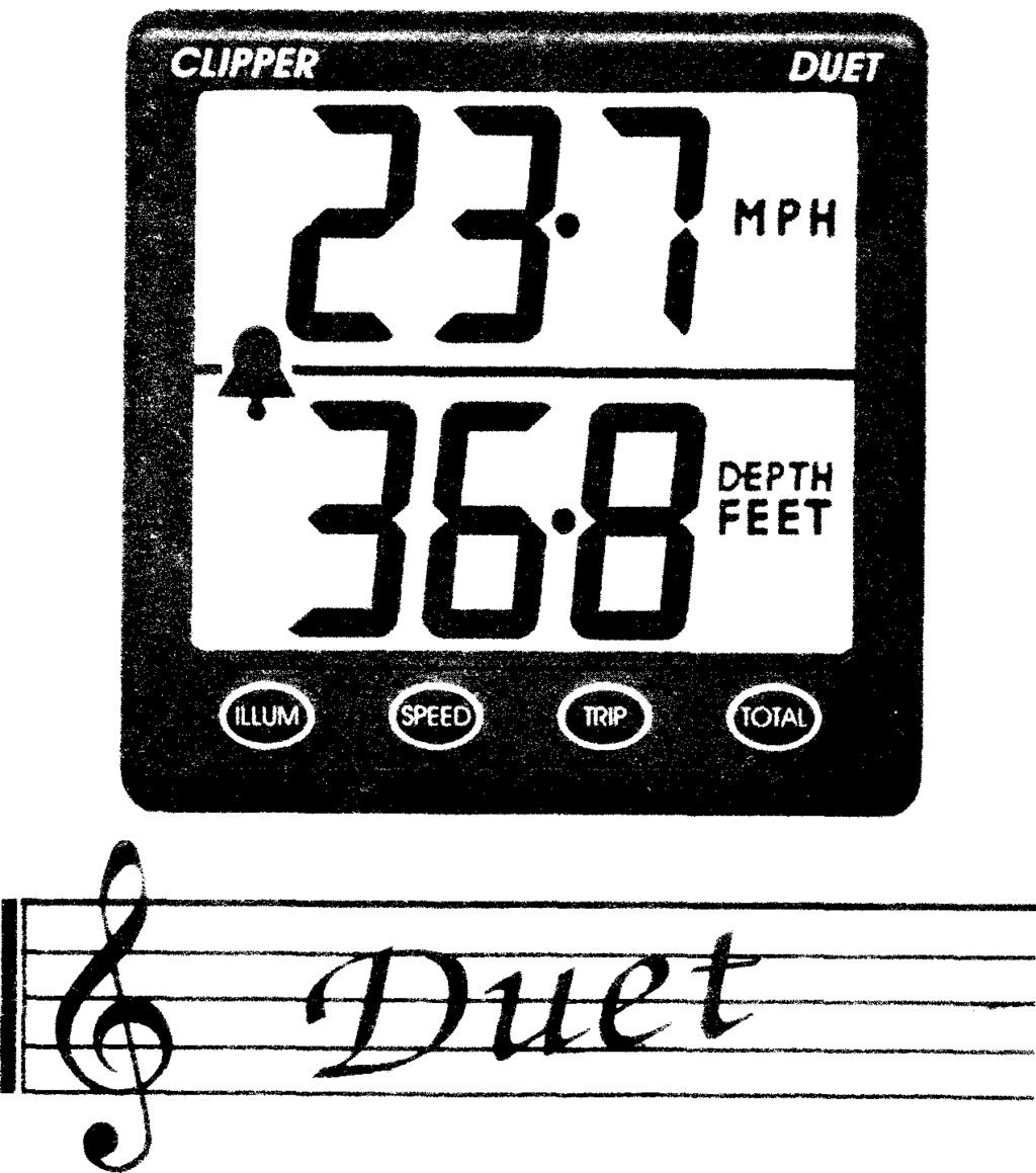
3 INTRODUCTION The Clipper Duet is a combined log and depth sounder. It is supplied complete with paddlewheel unit, transducer, and alarm bleeper. The Duet is designed to be powered from the vessel's 12 volt battery supply. INSTALLING THE DISPLAY Select a convenient position for the display on a panel or bulkhead. The site must be flat and the cavity behind the panel must remain dry at all times. (The cable entry is deliberately not sealed to ensure adequate ventilation. This prevents misting of the display). Cut a hole in the panel 87mm wide and 67mm high. Bring the wiring through the hole in the panel and connect the black wire to negative and red to positive. (See Figure 1). It is wise to use a fused supply to provide protection should a fault occur. The current consumption is very small, so any supply with at least a '/4 amp fuse is more than adequate. SUPPLY Figure 1 - Wiring Installation 2

4 With the vessel out of water, drill a hole of 42mm diameter through the hull to take the paddle housing and use conventional methods for sealing. It is advisable to avoid the use of mastic materials - use a form of proprietary silicon sealant. SILICONE/ SEA LAN T I I 42mm -+I I I NOTTOSCALE Figure 2 - Paddle Housing Installation (Sectioned view) The securing nut has a groove on its underside which should also be filled with sealing compound. Take care not to over tighten this nut. After the sealing compound has set, wipe off the excess and encapsulate the whole assembly in G.R.P. as shown on Figure 2. Take care to ensure that a minimum of 20mm of thread is clear at the top of the paddle housing. The paddle wheel unit can now be slid into the housing so that it is exposed to the water flow, with the arrow pointing forward along the centre line of the vessel. It is recommended that a little silicon grease is smeared over the rubber O-ring to keep the unit free. Tighten the retaining nut onto the top of the housing, and plug the cable into the paddlewheel socket on the display. For added protection it is again recommended that the plug is lightly covered with silicon grease. 4
5 INSTALLING THE ECHO SOUNDER TRANSDUCER The transducer can be mounted in one of three ways: (i) The transducer face can be bonded directly to the inside of the hull. (Some energy is lost to the hull but the loss in performance is, for most G.R.P hulls, hardly noticeable). (ii) A transom mount is available from your dealer. (iii) The transducer can be positioned inside a G.R.P. hull by means of an In Hull Transducer Kit. The latter method of installation offers the advantage that the transducer can easily be removed for examination or installation elsewhere. It should be mentioned however, that although the accuracy will in no way be affected by installing the transducer inside the hull, the maximum range sensitivity may be reduced, depending on the thickness and quality of the glass fibre. The In Hull Kit is available direct from NASA Marine or your local chandler. Whichever method is selected, the best location still has to be found. Select a position below the water level where the transducer will point substantially vertically downwards towards the seabed, and where the transducer and its cable (do NOT shorten the transducer cable) will be well clear of equipment which might be a source of interference. Such sources might include the engine ignition and starting systems, alternators and dynamos, electric pumps, etc. This position should also be well clear of large masses of bubbles or cavitation near propellers or sudden changes in hull profile which could disrupt the signal. 5
6 To test the suitability of the location when the vessel is in the water at a reasonable depth, press a little sticky chewing gum on the surface of the transducer and stick it down to the inside of the hull (it may be necessary to remove dirt and oily residue first). The unit can then be tested over a range of speeds and depths. If the location is satisfactory, the chewing gum must be removed and the transducer permanently mounted using one of the methods described previously. (Note: do NOT shorten the transducer cable). It is important that the face of the transducer is thoroughly bonded down to the hull. A single air bubble will cause a considerable loss in performance. The transducer and the place of mounting must be kept entirely free of any antifouling compound as this can also effect the performance of the unit. Plug the transducer into the transducer socket on the display. NOTES ON ELECTRICAL INTERFERENCE External electrical interference is characterised by persistent, random numbers on the display which obscure the true depth reading on the depth sounder. This is caused by large amplitude voltage spikes generally associated with the engine s alternator and/or ignition system which has not been properly suppressed. These spikes may find their way into the sensitive amplifier section of the depth sounder in two ways: (a) Through the craft s common power supply or (b) Through direct radiation from the source of interference. 6
7 To reduce the possibility of induced interference from the engine s generator and/or ignition system, choose a position as far away from the engine as possible and run the cable from the transducer as far as practicable from the engine. Do NOT cut the transducer cable, but stow excess away from any possible source of electrical interference. USING THE INSTRUMENT When power is connected to the instrument it will show the depth and boat speed. Pressing TRIP will show the trip distance, that is the distance since power was connected. Disconnecting the power will reset the TRIP to zero. Pressing TOTAL will show the accumulated total distance travelled. This total cannot be reset. Pressing ILLUM will turn on the display backlight. The lighting is concentrated over the active part of the display, the top corners being omitted. Pressing ILLUM again will turn the backlight off. Pressing SPEED will return to boat speed. The instrument will show depth at all times. If echo is temporarily lost then the depth units will momentarily flash. If the echo is completely lost then the display will show OUT. SETTlNG THE MINIMUM DEPTH ALARM This is done during normal operation. Press SPEED and TRIP simultaneously. The instrument will show SHA, the bell and the current minimum depth setting. Use TRIP to decrement the setting and TOTAL to increment the setting. When the required minimum depth setting has been selected press SPEED. This will enter the new value into memory and return to normal operation. To arm the alarm press TRIP and TOTAL simultaneously. Pressing TRIP and TOTAL simultaneously a second time will disable the alarm (without altering the alarm setting). The bell symbol will show only when the alarm is armed and will flash when the alarm is active. 7
8 SETTlNG THE SPEED ALARM The speed alarm will give an audible and visual warning if the boat speed exceeds a preset limit. To set this speed limit press SPEED and TOTAL simultaneously. The lower half of the display will show SPD, the upper half will show the current speed limit setting. Use TRIP to decrement and TOTAL to increment this value. (To disable the speed alarm decrement the value to zero where upon the display will show OFF). Pressing SPEED will enter this value into memory and return to normal operation. CHANGING THE OPERATING CONFIGURATION This allows the user to program the instrument to operate in the units of choice i.e. feet/metres, miles, nautical miles or kilometres. It also gives access to the gain threshold, the keel offset, the speed alarm and the log calibration settings. To enter the configuration mode press and keep depressed the ILLUM key whilst power to the instrument is switched on. When the key is released the display will show SET ENG. The instrument is now in the configuration mode. TO SELECT THE OPERATING UNITS Put the instrument into the configuration mode. The display will show SET ENG. Press TOTAL. The display will now show SET followed by the current speed units. (i.e. knots, miledhour or kilometres/hour). Use the TOTAL key to roster through the speed units. Press SPEED to enter the desired units. The display will briefly show CON to confirm the operation. The display will now show SET followed by the current depth units (i.e. feet or metres). Use the TOTAL key to select the desired units. Pressing SPEED will enter the desired units. 8
9 The display will briefly show CON to confirm the operation and then return to the SET ENG display. If no further settings are to be made then pressing the ILLUM key will exit the configuration mode and return to normal operation. SETTING THE KEEL OFFSET The Echo Sounder measures the depth from the transducer to the seabed. If the craft has a keel it is more often convenient to show the depth from the keel to the seabed. To operate in this way the depth of the keel (keel offset) must be entered into the instrument as follows: Put the instrument into the configuration mode. The display will now show SET ENG. Press SPEED, the upper half of the display will show USET and the lower half the current keel offset value. Use TRIP to decrement and TOTAL to increment this value. Pressing SPEED will enter this new value. The display will briefly show CON to confirm the operation and then return to the SET ENG display. If no further settings are to be made then pressing the ILLUM key will exit the configuration mode and return to normal operation. CHANGING THE GAIN THRESHOLD The Echo Sounder emits a high frequency pulse which bounces off the seabed back to the transducer. Echoes from nearby objects are much stronger than those from distant objects so an automatic gain control compensates for these different strength signals. However, reflections from nearby turbulence or bubbles can sometimes be confused with those from the bottom. To prevent nearby reflections from causing a problem, the sensitivity to nearby objects can be reduced. 9
10 The depth at which the sensitivity returns to normal is called the Gain Threshold. For example, if the Gain Threshold is set at 2 metres then the gain is low for echoes between 0 and 2 metres. The gain remains normal for echoes over 2 metres. To adjust the gain threshold put the instrument into the configuration mode. The display will show SET ENG. Press SPEED. The display will show the keel offset value. Press SPEED again, the upper half of the display mill show THR and the lower half the current Gain Threshold. Use TRIP to decrement and TOTAL to increment this value. Pressing SPEED will enter this new value. The display will briefly show CON to confirm the operation and then return to the SET ENG display. If no further settings are to be made then pressing the ILLUM key will exit the configuration mode and return to normal operation. CHANGING THE LOG CALIBRATION The calibration factor determines the number of revolutions of the paddle required to represent a fixed distance. The instrument is pre-calibrated in the factory. However, the type of hull and the position of the paddlewheel unit may affect the performance causing.the speed (and distance) to under-read or over-read. To correct any error, put the instrument into the configuration mode. The display will show SET ENG. Press TRIP. The display will show CAL and the current calibration factor (which is factory set to 100% to give correct readings in free flow conditions). The factor can be incremented to a total of 150% by pressing TOTAL and can be decremented to a minimum of 70% by pressing TRIP. 10
11 I ', The general rule is that if the instrument over-reads, the factor must be reduced, and if it under-reads, the factor must be increased, the percentage error in the readings is the same percentage change that must be made. For example if the instrument is found to under-read by 6% then the calibration factor should be increased by 6%. Pressing SPEED will enter a new calibration factor and return to the SET ENG display. If no further settings are to be made then pressing the ILLUM key will exit the configuration mode and return to normal operation. 11
CLIPPER DUET M P H DEPTH F E E T SPEED TOTAL TRIP ILLUM. Duet COMBINED LOG AND ECHO SOUNDER
 CLIPPER DUET M P H DEPTH F E E T ILLUM SPEED TRIP TOTAL Duet CLIPPER DUET COMBINED LOG AND ECHO SOUNDER INTRODUCTION INSTALLING THE DISPLAY INSTALLING THE LOG PADDLE WHEEL UNIT INSTALLING THE ECHO SOUNDER
DESIGNED AND MANUFACTURED IN ENGLAND CLIPPER DEPTH DEPTH METRES ECHO SOUNDER.
 DESIGNED AND MANUFACTURED IN ENGLAND CLIPPER DEPTH DEPTH 7 METRES ECHO SOUNDER INTRODUCTION 2 INSTALLING THE DISPLAY 2 INSTALLING THE TRANSDUCER 3 NOTES ON ELECTRICAL INTERFERENCE 5 GETTING STARTED 5 OPERATIONAL
CLIPPER DEPTH METRES ENTER SHALL DEEP ILLUM CLIPPER ECHO SOUNDER
 CLIPPER DEPTH DEPTH DUET CLIPPER ECHO SOUNDER INTRODUCTION INSTALLING THE DISPLAY INSTALLING THE TRANSDUCER NOTES ON ELECTRICAL INTERFERENCE GETTING STARTED OPERATIONAL CONTROLS BACKLIGHT SETTING CHANGING
INSTALLATION AND USER INSTRUCTIONS for TARGET 2 LOG, DEPTH & WIND MARINE INSTRUMENTS
 INSTALLATION AND USER INSTRUCTIONS for TARGET 2 LOG, DEPTH & WIND MARINE INSTRUMENTS NASA MARINE LTD BOULTON ROAD STEVENAGE HERTS. SG1 4QG (01438) 354033 1: INTRODUCTION Target instruments are designed
WIND CLIPPER KTS ILLUM SCALE INC DEC CLIPPER WIND SYSTEM
 CLIPPER WIND KTS ILLUM SCALE DEC INC CLIPPER WIND SYSTEM TABLE OF CONTENTS INTRODUCTION PRE-TEST OF INSTRUMENT INSTALLING THE MASTHEAD SENSOR UNIT INSTALLING THE DISPLAY NORMAL OPERATION CHANGING THE
Depth sensor. Product reference : REV 1. USER GUIDE and INSTALLATION GUIDE. nke Sailing competition
 Depth sensor Product reference : 90-60-456 REV 1 USER GUIDE and INSTALLATION GUIDE nke Sailing competition Z.I. Kerandré Rue Gutenberg 56700 HENNEBONT- FRANCE http://www.nke.fr After sale service n 33
Copyright 2004 by the Thomas G. Faria Corporation, Uncasville CT No part of this publication may by reproduced in any form, in an electronic
 Copyright 2004 by the Thomas G. Faria Corporation, Uncasville CT No part of this publication may by reproduced in any form, in an electronic retrieval system or otherwise, without the prior written permission
USER GUIDE FOR DATALINE-X SDX. Stowe Marine Ltd. Tel +44(0)
") USER GUIDE FOR DATALINE-X SDX Stowe Marine Ltd. www.stowemarine.com Tel +44(0)1590 610071 Dataline-X SDX Manual, Part Number 05707SM, Issue 2, Dec 1995. Warning The equipment to which this manual applies
USER GUIDE FOR DATALINE-X SDX Stowe Marine Ltd. www.stowemarine.com Tel +44(0)1590 610071 Dataline-X SDX Manual, Part Number 05707SM, Issue 2, Dec 1995. Warning The equipment to which this manual applies
ST60 Depth Instrument Owner s Handbook. Document number: Date: 1 April 2004
 ST60 Depth Instrument Owner s Handbook Document number: 81038-4 Date: 1 April 2004 Raymarine, ST60 and SeaTalk are trademarks of Raymarine Limited Handbook contents copyright Raymarine Limited 2004 Preface
Operating instructions Installation instructions To be kept in the vehicle!
 ON OFF Sonatic Sonatic Level indicator for gas cylinders (Type GB) h Operating instructions Installation instructions To be kept in the vehicle! Service (UK and Eire) Tel. (0 12 83) 51 10 92 Fax (0 12
SR MARINER DIGITAL DEPTH METER DDM- 1 DDM- 2 INSTALLATION INSTRUCTIONS
 SR MARINER DIGITAL DEPTH METER DDM- 1 DDM- 2 INSTALLATION INSTRUCTIONS Congratulatio n s in choosing a high perfor m a n c e marine instru m e n t and welcome to the growing family of SR Mariner produc
FISH 4100 / Installation and Operation Manual. English... 3 Français Español Português
 FISH 4100 / 4150 Installation and Operation Manual English... 3 Français... 24 Español... 46 Português...68 www.navman.com FCC Statement Note: This equipment has been tested and found to comply with the
Horizon Strike 200/220s
 Horizon Strike 200/220s Fishfinder Owner s Manual MARINE PRODUCTS LIMITED WARRANTY Standard Communications Corp. (SCC) warrants to the original consumer purchaser (the Purchaser) only that each new Marine
ST40 Bidata Instrument Owner s Handbook. Document number: Date: March 2006
 Bidata Instrument Owner s Handbook Document number: 81159-3 Date: March 2006 Raymarine, and SeaTalk are trademarks of Raymarine UK Ltd Handbook contents copyright Raymarine UK Ltd. Preface i Important
PIRANHA I & 2 OPERATION GUIDE
 PIRANHA I & 2 OPERATION GUIDE Thank You Thank you for purchasing a Piranha fishfinder from Humminbird, America s #1 Manufacturer of quality consumer marine electronics WARNING! This device should not be
WIND. - Instrument - Installation and Operation Manual English
 - Instrument - Installation and Operation Manual 1 Introduction Thank you for choosing Star Wind instrument. We are convinced that you will appreciate all the valuable information either you are a cruiser
ECHO MANUAL WARNING. L B A ltim e te rs. ECHO is a trademark of LB Altimeters, Denmark
 ECHO MANUAL L B A ltim e te rs ECHO is a trademark of LB Altimeters, Denmark LB Altimeters operates a policy of continuous development Therefore, we reserve the right to make changes and improvements to
What hull material types will the system work on? Do I still need an antifoul paint?
 1. The Hull What hull material types will the system work on? The system is effective on all GRP (Glass Reinforced Plastic), STEEL and ALUMINIUM hulls up to thickness of 70mm. Unfortunately the system
INTRODUCTION TO NETWORK WIND 3 MOUNTING THE UNIT 14 SELECTING THE DISPLAY MODE 5 ABBREVIATIONS AND DEFINITIONS 17
 CONTENTS CONTENTS 1 INSTALLATION 14 GENERAL INTRODUCTION TO B&G NETWORK 2 SITING THE UNIT 14 INTRODUCTION TO NETWORK WIND 3 MOUNTING THE UNIT 14 EXAMPLE SYSTEMS USING NETWORK WIND 4 SPECIFICATION 16 SELECTING
ST60+ Depth Instrument Owner s Handbook
 ST60+ Depth Instrument Owner s Handbook Document reference: 81262-2 Date: December 2005 Raymarine, ST60+ and SeaTalk are trademarks of Raymarine UK Limited Handbook contents copyright Raymarine UK Limited
OPERATION AND INSTALLATION MANUAL
 AP46 Autopilot OPERATION AND INSTALLATION MANUAL www.tmq.com.au TMQ AP46 Autopilot Page 1 of 34 Ver1.0 07/03/2007 This page is Blank TMQ AP46 Autopilot Page 2 of 34 Ver1.0 07/03/2007 WARNING!...4 INTRODUCTION...5
TOP BLEED Position for SeaTalk 2 colour logo ST 30. COMPASS Operation and Installation
 Distributed by Any reference to Raytheon or RTN in this manual should be interpreted as Raymarine. The names Raytheon and RTN are owned by the Raytheon Company. TOP BLEED Position for SeaTalk 2 colour
New product release. Universal Rebreather Monitor (URBM) Single O2 cell and Dual HP package
 Single O2 cell and Dual HP package") New product release Closed Circuit Research is pleased to announce the launch of our range of Universal Rebreather Monitors Key features and benefits include: Universal Rebreather Monitor (URBM) Single
New product release Closed Circuit Research is pleased to announce the launch of our range of Universal Rebreather Monitors Key features and benefits include: Universal Rebreather Monitor (URBM) Single
Depth transducer TH 52
 Depth transducer TH 52 performance by NEXUS NETWORK Installation Manual English DEPTH TH52 English 11-1 English DEPTH TH52 11-2 DEPTH TH52 English CONTENTS: 1 Applications...4 2 Tools and Materials Needed...4
Stand-Alone Bubble Detection System
 Instruction Sheet P/N Stand-Alone Bubble Detection System 1. Introduction The Bubble Detection system is designed to detect air-bubble induced gaps in a bead of material as it is being dispensed. When
Model PSI Compressor with 3-Gallon Air Tank 12VDC
 Model 6350 150 PSI Compressor with 3-Gallon Air Tank 12VDC IMPORTANT: It is essential that you and any other operator of this product read and understandd the contents of this manual before installing
Model No. D10D INSTALLATION AND OPERATION MANUAL D10DX.01T Digital Depth Sounder with Air & Water Temperature, Transom Mount Transducer
 Model No. D10D INSTALLATION AND OPERATION MANUAL D10DX.01T Digital Depth Sounder with Air & Water Temperature, Transom Mount Transducer SAFETY INFORMATION: To ensure safety and many years of trouble-free
Installation, Compensation and Maintenance Instructions for. RITCHIE Compasses. Made In U.S.A
 Installation, Compensation and Maintenance Instructions for RITCHIE Compasses Made In U.S.A All Magnetic Compasses are vulnerable to magnetic interference, which will produce errors, called deviation.
ST30 Round Bidata Owner s Handbook
 ST30 Round Bidata Owner s Handbook Document number: 81075_4 Date: 1st April 2001 Copyright Raymarine Limited 2001 Preface i Important information WARNING Although your ST30 instrument is designed to give
Installation, Operation and Maintenance Instructions for Electronically Controlled Pressurisation Units
 Installation, Operation and Maintenance Instructions for Electronically Controlled Pressurisation Units Models: EPS Single Pump EPT Twin Pump EPS-HP EPT-HP Single Pump High Pressure Twin Pump High Pressure
Paddle Bar Replacement
 This procedure is to help facilitate the replacement of the 23 Paddle Bar Assembly on the ANKOM Dietary Fiber Analyzer. Note: The following items will be sent in a replacement package as part of the 23
INSTALLATION PREPARATION
 PARTS SUPPLIED INSTALLATION PREPARATION PARTS SUPPLIED Before installing your new Humminbird fishfinder, please ensure the following parts are included in the box: Fishfinder Transducer with 20 (6m) of
200 PSI COMPRESSORS - MODEL NUMBERS
 200 PSI COMPRESSORS - MODEL NUMBERS 380C AIR COMPRESSOR KIT PART NO. 38033 480C AIR COMPRESSOR KIT PART NO. 48043 380C 480C IMPORTANT: It is essential that you and any other operator of this product read
IMPORTANT SAFETY INSTRUCTIONS
 IMPORTANT SAFETY INSTRUCTIONS CAUTION - To reduce risk of electrical shock: - Do not disassemble. Do not attempt repairs or modifications. Refer to qualified service agencies for all service and repairs.
Ultrasonic Antifouling Systems
 HOW DOES IT WORK? The Sonihull and Oceonic antifouling systems work by eliminating the first part of the food chain (ie. algae). If you prevent the food source barnacles and other marine life will not
97C COMPRESSOR KIT 12V PART NO C COMPRESSOR KIT 24V PART NO C COMPRESSOR KIT PART NO
 97C COMPRESSOR KIT 12V PART NO. 00097 97C COMPRESSOR KIT 24V PART NO. 02497 98C COMPRESSOR KIT PART NO. 00098 97C 98C IMPORTANT: It is essential that you and any other operator of this product read and
420C AIR COMPRESSOR KIT PART NO C AIR COMPRESSOR KIT PART NO
 420C AIR COMPRESSOR KIT PART NO. 42042 460C AIR COMPRESSOR KIT PART NO. 46043 420C 460C IMPORTANT: It is essential that you and any other operator of this product read and understand the contents of this
Operations Manual. Internal automatic Pressure control for orbital tube welding. By Exel Orbital Systems, Inc. Page
 Operations Manual Internal automatic Pressure control for orbital tube welding. By Exel Orbital Systems, Inc. Page SG1 Overview and Dimensions 5.25 / 133 mm PS Power Supply Connection 4.06 / 103 mm Top
100C Air Compressor Kit
 10010 100C Air Compressor (standard mounting bracket, CE Spec) 10014 100C Air Compressor (no leader hose or check valve, CE Spec) 10016 100C Air Compressor (with Omega Bracket, CE Spec) IMPORTANT: It is
9A5N Solid State CW Paddle
 9A5N Solid State CW Paddle User manual Table of contents: 1. General description 2. Before you begin 3. Finger piece and/or battery installation 4. Interconnection 5. Lever(s) sensitivity adjustment 6.
444C DUAL PERFORMANCE VALUE PACK
 (Chrome) PART NO. 44432 IMPORTANT: It is essential that you and any other operator of this product read and understand the contents of this manual before installing and using this product. SAVE THIS MANUAL
400C & 450C DUAL PERFORMANCE VALUE PACKS
 (Chrome) PART NO. 40013 (Silver) PART NO. 45012 (Chrome) PART NO. 45013 IMPORTANT: It is essential that you and any other operator of this product read and understand the contents of this manual before
RAM Operation Manual. Worldwide Manufacturer of Gas Detection Solutions
 RAM 4021 Operation Manual Worldwide Manufacturer of Gas Detection Solutions TABLE OF CONTENTS RAM 4021 For Your Safety... 2 Description.... 2 Setup Mode.... 2 Lights/Alarms.... 3 Operation.... 4 Calibration....
MP15 Jockey Pump Controller
 Setup and Operating Instructions MP15 Jockey Pump Controller This manual provides general information, installation, operation, maintenance, and system setup information for Metron Model MP15 Jockey Pump
USER S GUIDE DepthTrax 1H HawkEye Portable Depth Finder (DT1H)
") USER S GUIDE DepthTrax 1H HawkEye Portable Depth Finder (DT1H) Thank you for purchasing a HawkEye product, and welcome to the innovations of NorCross Marine Products, Inc. To ensure safety and many years
USER S GUIDE DepthTrax 1H HawkEye Portable Depth Finder (DT1H) Thank you for purchasing a HawkEye product, and welcome to the innovations of NorCross Marine Products, Inc. To ensure safety and many years
Heavy Duty Dissolved Oxygen Meter
 User's Manual Heavy Duty Dissolved Oxygen Meter Model 407510 Test Equipment Depot - 800.517.8431-99 Washington Street Melrose, MA 02176 FAX 781.665.0780 - TestEquipmentDepot.com Introduction Congratulations
INSTALLATION.. 6 Transom Installation... 6 Inside the Hull Installation. 10 Control Head Installation Test the Installation 15
 TABLE OF CONTENTS INSTALLATION PREPARATION 2 Parts Supplied. 2 Accessories. 2 Installation Overview.. 2 Alternative Transducers and Mounting Methods... 4 Transducer Exchange 5 INSTALLATION.. 6 Transom
RAM 4021-PR. Operation Manual. Worldwide Manufacturer of Gas Detection Solutions
 RAM 4021-PR Operation Manual Worldwide Manufacturer of Gas Detection Solutions TABLE OF CONTENTS RAM 4021-PR For Your Safety... 2 Description.... 2 Setup Mode.... 2 Lights/Alarms.... 3 Operation.... 4
MODEL NUMBER: M20005 AIR SOURCE KIT. 30% Duty Compressor on. 2.0 Gallon Air Tank SAVE THIS MANUAL FOR FUTURE REFERENCE
 MODEL NUMBER: M20005 AIR SOURCE KIT 30% Duty Compressor on 2.0 Gallon Air Tank SAVE THIS MANUAL FOR FUTURE REFERENCE USER MANUAL IMPORTANT SAFETY INSTRUCTIONS CAUTION - To reduce risk of electrical shock
200 PSI HIGH-FLOW AIR SOURCE KIT
 200 PSI HIGH-FLOW AIR SOURCE KIT 50% Duty Compressor on 2.0 Gallon Air Tank PART NO. 20008 IMPORTANT: It is essential that you and any other operator of this product read and understand the contents of
RAM Operation Manual. Worldwide Manufacturer of Gas Detection Solutions
 RAM 4021 Operation Manual Worldwide Manufacturer of Gas Detection Solutions TABLE OF CONTENTS RAM 4021 For Your Safety... 2 Description.... 2 Setup Mode.... 2 Lights/Alarms.... 3 Operation.... 4 Calibration....
ACV-10 Automatic Control Valve
 ACV-10 Automatic Control Valve Installation, Operation & Maintenance General: The Archer Instruments ACV-10 is a precision automatic feed rate control valve for use in vacuum systems feeding Chlorine,
250C-IG COMPRESSOR KIT 12V PART NO C-IG COMPRESSOR KIT 24V PART NO
 250C-IG COMPRESSOR KIT 12V PART NO. 25050 250C-IG COMPRESSOR KIT 24V PART NO. 25058 IMPORTANT: It is essential that you and any other operator of this product read and understand the contents of this manual
250C-IG COMPRESSOR KIT 12V PART NO C-IG COMPRESSOR KIT 24V PART NO
 250C-IG COMPRESSOR KIT 12V PART NO. 25050 250C-IG COMPRESSOR KIT 24V PART NO. 25058 IMPORTANT: It is essential that you and any other operator of this product read and understand the contents of this manual
GV Standard X-Vent. Setup, Commissioning & Installation Guide
 GV Standard X-Vent Setup, Commissioning & Installation Guide Technical experts in the design, manufacture and supply of precision engineered, architectural rooflights for residential and commercial buildings.
120 PSI FAST-FILL AIR SOURCE KIT 25% Duty Compressor on 1.5 Gallon Air Tank
 120 PSI FAST-FILL AIR SOURCE KIT 25% Duty Compressor on 1.5 Gallon Air Tank PART NO. 20003 IMPORTANT: It is essential that you and any other operator of this product read and understand the contents of
EMC Conformance. Important
 Digital Display mn100 Digital Display EMC Conformance All Raymarine equipment is designed to the best industry standards for use in the recreational marine environment. The design and manufacture of Raymarine
Sincerely, Trevor Sumption President, Grayden Outdoor, LLC.
 Thank you for your purchase. For over 30 years anglers have relied on Fish Hawk Electronics to give them accurate speed and water temperature information to help them catch more fish. As a family owned
TS1. Ultrasonic Tank Sender. Installation and Operating Instructions. For TS1 Firmware v3.8. Page 1 INST-TS1-V13 18/11/10
 TS1 Ultrasonic Tank Sender Installation and Operating Instructions For TS1 Firmware v3.8 Page 1 Table of Contents 1. FEATURES... 3 2. SPECIFICATIONS... 3 3. DIMENSIONS... 4 4. MOUNTING AND INSTALLATION...
Aquavar SOLO 2 Frequently Asked Questions
 Aquavar SOLO 2 Frequently Asked Questions How do I size the Aquavar SOLO 2 for the appropriate pump/motor combination? Can I use a 208 Volt motor? Can I run the Aquavar SOLO 2 up to 80HZ? What are the
ECONORESS ELECTRONIC EPS & EPT - ENHANCED PRESSURISATION SET INSTALLATION OPERATION & MAINTENANCE DOCUMENTATION
 ECONORESS ELECTRONIC EPS & EPT - ENHANCED PRESSURISATION SET INSTALLATION OPERATION & MAINTENANCE DOCUMENTATION OCT2010 STOKVIS ENERGY SYSTEMS 96R WALTON ROAD EAST MOLESEY SURREY KT8 0DL TEL: 020 87833050
mn100 Analog Display
 mn100 Analog Display uu040 rev. 8 mn100 Analog Display EMC Conformance All Tacktick equipment is designed to the best industry standards for use in the recreational marine environment. The design and manufacture
How to calibrate the formaldehyde sensor within a PPMonitor Wireless Unit:
 How to calibrate the formaldehyde sensor within a PPMonitor Wireless Unit: Please read this document thoroughly before attempting to check or adjust the calibration of the formaldehyde sensor within the
Installation and operating manual. Pneumatic control station LK product no: PCS 1-10
 LK product no: PCS 1-10 Article no: 74503 Revision:8 Article no: 74503 Revision: 8 2 (23) Contents 1. General information... 5 2. Safety precautions... 5 2.1 Significance of symbols... 5 2.2 Explanatory
ACCURACY, PERFORMANCE, AND HANDLING OF OIL-FILLED DIGIQUARTZ PRESSURE INSTRUMENTATION
 Application Note Doc. G8108-001 Rev. A - 23-Jul-02 ACCURACY, PERFORMANCE, AND HANDLING OF OIL-FILLED DIGIQUARTZ PRESSURE INSTRUMENTATION For more information regarding Digiquartz products contact: Paroscientific,
PLAQUE MFM0680 UNDERWATER LIGHT. Operating Instructions
 PLAQUE MFM0680 UNDERWATER LIGHT Operating Instructions CONTENTS Preface... 3 Features... 3 Precautions... 3 Controls and Connectors... 4 Underwater Light PLAQUE MFM0680... 4 Power Supply Unit MPS021000
200 PSI FAST-FILL AIR SOURCE KIT
 200 PSI FAST-FILL AIR SOURCE KIT 55% Duty Compressor on 2.0 Gallon Air Tank PART NO. 20007 IMPORTANT: It is essential that you and any other operator of this product read and understand the contents of
Inverse Prop. Pressure-Relief Cart., Size 2 4
 Inverse Prop. Pressure-Relief Cart., Size Q max = l/min (6 gpm), p max = bar (58 psi) Direct acting, electrically operated Description inverse proportional pressure-relief valves are direct acting screw-in
New product release. Universal Rebreather Monitor (URBM) Three cell / Independent backup
 Three cell / Independent backup") New product release Closed Circuit Research is pleased to announce the launch of our range of Universal Rebreather Monitors Universal Rebreather Monitor (URBM) Three cell / Independent backup Key features
New product release Closed Circuit Research is pleased to announce the launch of our range of Universal Rebreather Monitors Universal Rebreather Monitor (URBM) Three cell / Independent backup Key features
Proportional Pressure-Relief Cartridge Valve, Size 2...4
 Proportional Pressure-Relief Cartridge Valve, Size... Q max = l/min, p max = 3 bar Direct acting, electrically operated 1 Description proportional pressure-relief valves are direct acting screw-in cartridges
GILMONT ACCUCAL FLOWMETERS
 OPERATING MANUAL GILMONT ACCUCAL FLOWMETERS 28W092 Commercial Ave. Barrington, IL U.S.A. 60010-2392 (847) 381-4888 (847) 381-7053 (Fax) 800-962-7142 www.barnant.com e-mail: barnant@barnant.com A-1299-0766
INTERNATIONAL MARITIME ORGANIZATION
 Page 1 of 16 INTERNATIONAL MARITIME ORGANIZATION IMO Resolution A.586(14) REVISED GUIDELINES AND SPECIFICATIONS FOR OIL DISCHARGE MONITORING AND CONTROL SYSTEMS FOR OIL TANKERS. ANNEX This document quote
StockWeigh 500 D3632 US-B
 OPERATORS MANUAL DIGI-STAR 790 WEST ROCKWELL AVENUE FORT ATKINSON, WISCONSIN 53538 PHONE: (920) 563-1400 TECHNICAL SERVICE: 1-800-225-7695 (920) 563-9700 D3632 US- Rev. B August 4, 2004 StockWeigh 500
PART 5 - OPTIONS CONTENTS 5.1 SYSTEM EXPANSION 5-3
 PART 5 - OPTIONS CONTENTS Para Page 5.1 SYSTEM EXPANSION 5-3 5.2 SENSORS 5-3 5.2.1 Trim Angle Sensor 5-3 5.2.2 Mast Rotation Sensor 5-3 5.2.3 Heel Angle Sensor 5-3 5.2.4 Barometric Pressure Sensor 5-3
High-performance submersible pressure transmitter For level measurement Model LH-10
 Electronic pressure measurement High-performance submersible pressure transmitter For level measurement Model LH-10 WIKA data sheet PE 81.09 Applications Level measurement in rivers and lakes Deep well
Installation, Operation and Maintenance Instructions for Electronically Controlled Pressurisation Units
 Installation, Operation and Maintenance Instructions for Electronically Controlled Pressurisation Units Micro-S / Micro-S Digital Wall Hung Unit Please fulfil all listed requirements prior to and during
AUTOMATIC GAS MANIFOLDS
 AUTOMATIC GAS MANIFOLDS Phoenix Pipeline Products Limited. Unit 8, McKenzie Industrial Park, Tel No.: 44 (0) 161 428 7200 Bird Hall Lane, Fax No.: 44 (0) 161 428 7010 Stockport, Email: info@p3-phoenix.com
IMPORTANT SAFETY INSTRUCTIONS READ AND FOLLOW ALL INSTRUCTIONS SAVE THESE INSTRUCTIONS
 Warrior D.E. Filter Operating Procedures IMPORTANT SAFETY INSTRUCTIONS READ AND FOLLOW ALL INSTRUCTIONS SAVE THESE INSTRUCTIONS Table of Contents SECTION I. FILTER INSTALLATION... 1 SECTION II. FILTER
A4 Operation Manual. Fig.1-1 Controller Socket Diagram
 A4 Operation Manual Safety Instruction Please read this manual carefully, also with related manual for the machinery before use the controller. For installing and operating the controller properly and
Manual Leveling Control Installation/Operation
 ELECTROMECHANICAL TRIM TAB SYSTEMS Manual Leveling Control Installation/Operation Linear Devices Corporation dba Lectrotab 11126 Air Park Road, Suite G Ashland, VA 23005 www.lectrotab.com Phone: 804-368-8428
Planning and general precautions ithrust Tunnel Systems installations.
 Version 1.0 This recommendation will go through the different factors to consider when choosing where and how to fit thruster tunnels in a boat. Some of these recommendations might be difficult, or even
Installation manual. 38/200 Combi D Echo sounder transducer. M A X I M I Z I N G Y O U R P E R F O R M A N C E A T S E A
 Installation manual 38/200 Combi D Echo sounder transducer www.simrad.com M A X I M I Z I N G Y O U R P E R F O R M A N C E A T S E A 851-165215 / Rev.A Simrad 38/200 Combi D Transducer Installation manual
RAM 4021 Operation Manual
 RAM 4021 Operation Manual Worldwide Manufacturer of Gas Detection Solutions TABLE OF CONTENTS RAM 4021 For your safety...3 Description...3 Set-up mode...4 Annunciator lights/alarms...4 Operation...5 Calibration...6
AP55 Display OPERATION AND INSTALLATION MANUAL.
 AP55 Display OPERATION AND INSTALLATION MANUAL www.tmq.com.au Index INDEX... 2 INTRODUCTION... 3 System configuration... 3 System Block Diagram... 4 Definition of Terms... 6 Overview of Operation... 8
Simple, Robust, Reliable Measures ph Doses either acid (lower) or alkali (raise) Displays ph, Total Dose Count (DCT) and Dose Count per hour (DC/h)
 or alkali (raise) Displays ph, Total Dose Count (DCT) and Dose Count per hour (DC/h)") Simple, Robust, Reliable Measures ph Doses either acid (lower) or alkali (raise) Displays ph, Total Dose Count (DCT) and Dose Count per hour (DC/h) Integrated peristaltic dosing pump When using automatic
Simple, Robust, Reliable Measures ph Doses either acid (lower) or alkali (raise) Displays ph, Total Dose Count (DCT) and Dose Count per hour (DC/h) Integrated peristaltic dosing pump When using automatic
LINDGREN-PITMAN, INC. LS-3 / LS-4 Line Setter
 LINDGREN-PIAN, INC. LS-3 / LS-4 Line Setter MOUNTING The Lindgren-Pitman Line Setter should be mounted on or near the transom of the boat such that the line will fall overboard as it leaves the exit. The
user leaflet GAUGING TRANSDUCERS
 user leaflet Solartron Metrology Gauging Transducers are high precision measurement probes intended for all gauging applications demanding high accuracy and a high degree of repeatability. The one piece
FULL OPERATING INSTRUCTIONS FOR MODELS AE 50/100 and/or AE 160/200
 FULL OPERATING INSTRUCTIONS FOR MODELS AE 50/100 and/or AE 160/200 The single pan electronic balance works off of the theory of a double pan mechanical balance, but is a much faster and unencumbered process.
Installation and Operating Instructions for Blow Down Controller Type LRR 1-12
 LRR1-12 8010 GENERAL PURPOSE & APPLICATION 1) Continuous monitoring of the conductivity of water within steam boilers, evaporators and similar plants with the added facility of temperature monitoring and
NORMAL OPERATING DISPLAYS GENERAL OPERATION
 SunTapWat e rsys t e ms WS1Cl ac kwat e rsof t ne r Owne r smanual MAIN COMPONENTS Your water treatment system is a point of entry (POE) system composed of three components: A. The control valve and computer
TECHNICAL DATA MAINTENANCE AIR COMPRESSOR MODEL G-1
 Dry 131h 1. DESCRIPTION The Viking Model G-1 Maintenance Air Compressor is an electric motor-driven, aircooled, single-stage, oil-less compressor. The unit is equipped with a check valve and provides a
SEAFARER 5 ECHO SOUNDER. I nstallation and Operating Instructions
 I Seafarer 5 SEAFARER RANGE SEAFARER 5 ECHO SOUNDER I nstallation and Operating Instructions SEAFARER NAVIGATION INTERNATIONAL LIMITED Fleets Lane, Poole, Dorset BH15 3BW, England Telephone: Poole 674641
LS-UT Ultrasonic Level Transmitter
 Four Elms Road Edenbridge Kent TN8 6AB UK Features & Benefits Maintenance free Simple set-up procedure IP86 housing (2m for 24 hours) Low consumption Locking nut supplied Technical Overview The LS-UL ultrasonic
RAM 4021-DPX Operation Manual
 RAM 4021-DPX Operation Manual Worldwide Manufacturer of Gas Detection Solutions TABLE OF CONTENTS ABL 4021-DPX / RAM 4021-DPX For Your Safety... 3 Description... 3 Setup Mode... 4 Lights/Alarms... 4 Operation...
Proportional Pressure-Relief Cartridge Valve, Size 2...4
 Proportional Pressure-Relief Cartridge Valve, Size... Q max = l/min (6 gpm), p max = bar (58 psi) Direct acting, electrically operated Description proportional pressure-relief valves are direct acting
User's Manual. Heavy Duty Dissolved Oxygen Meter. Model
 User's Manual Heavy Duty Dissolved Oxygen Meter Model 407510 Introduction Congratulations on your purchase of Extech's Heavy Duty Dissolved Oxygen / Temperature Meter which simultaneously displays Dissolved
INSTRUCTION MANUAL FOR MODEL 7360V VERTICAL CURING CHAMBER Revision E May
 INSTRUCTION MANUAL FOR MODEL 7360V VERTICAL CURING CHAMBER Revision E May 2015 98-0520 S/N 2001 N. Indianwood Ave. Tulsa, Oklahoma 74012 U.S.A. TEL: (918) 250-7200 FAX: (918) 459-0165 E-mail: chandler.sales@ametek.com
Remote Control Bait Boat
 CARPIO 2.0 User Manual All pictures shown are for illustration purpose only. Actual product may vary due to product enhancement Remote Control Bait Boat (Smart Remote Control at 868 MHz) 1 Table of Contents
Sondaloop and MiniSonda Version 2 Ultrasonic Level Transmitter
 Sondaloop and MiniSonda Version 2 Ultrasonic Level Transmitter Installation & Setting up Instructions Hawker Electronics Limited O&M 82 57 The Avenue Issue H Rubery Industrial Estate APR 2017 Birmingham
Do Not Print This Page.
 Do Not Print This Page. Load 1 sheet of cardstock paper. Print Page 2 - the cover For the body of the text, load 3 sheets of 28lb matte finish paper into the printer. Print pages 3, 5, 7 (Sheet 1, 2, 3)