User Manual. FlowAnalyser
|
|
|
- Marianna Maxwell
- 5 years ago
- Views:
Transcription
1 User Manual FlowAnalyser
2
3 1 Content 1 Content Preface Intended Use Safety Instructions Symbols for Danger, Warnings and Notes Personnel Responsibilities and Guarantees Technical Data Measurement Categories Analyser Values Respiratory Parameters Principle of Operation for Flow Measurement Special Functions Communication Interfaces Physical Data Calibration by User Operational Data Extras Standard Conditions for Flow Measurement Power Supply Battery Mode Compliance and Approvals Device Labels and Symbols Minimum PC Requirements Preparing for Use Individual Supplied Parts Power Supply Supply Voltage Mechanical Connections Protection Filter FlowAnalyser TM Adapter Set Low Flow High Flow Differential Pressure Low pressure (PF-302 LOW) Pressure sensor +/- 1 bar (PF-301 VAC) High Pressure Electrical Interfaces USB Ethernet RS External Trigger Grounding Version 2.1 Page 3 of 81
4 7 Operation Switching the Device On and Off The Start Screen Adjusting the Contrast Description of Operating Controls Specifications for the Operating Controls Numerical Display Specification for the Numerical Display Configuration Display Specification for the Configuration Display Statistics Display Specification of the Statistics Display Menu Display Specification of the Menu Display Data Storage Capabilities Storing Data Retrieving Data Erasing Data Calibrations Calibrating the Pressure and Flow Sensors Calibrating the Oxygen Sensor Calibrating the MultiGasAnalyser TM OR Gas Type and Standard Setting the Volume Trigger Selection of Ventilation Mode Standard Trigger Detailed Trigger Settings Usage of an External Volume Trigger Filter Setting the Language HW Activation Accessing System Info Invisible Menu Options Factory Defaults FlowLab TM Software Installation USB Communication Overview Options Panels Configuration Curve Trigger Cursors Numerics Trending Configuration Display Reporting Configuration Gas Calculator FlowLab TM Settings Page 4 of 81 Version 2.1
5 9 MultiGasAnalyser TM OR Description Intended use Warnings Design and theory How to connect LED Signal Calibration of Sensor head Preventive maintenance Specifications MultiGasAnalyser TM OR Measuring Respiratory Coefficients General Connection to the Ventilator Standard Trigger Values Baseflow Finding the Correct Trigger Values Flow curve after Y-Piece Flow curve before Y-Piece Pressure curve before Y-Piece Special situations Inspiration Volume Vti Expiration Volume Vte Care and Maintenance Guidelines for Care and Maintenance Notes on Replacing Components Preventative Cleaning and Maintenance Routines Replacing the Measuring Screen Replacing the Oxygen Sensor Replacing the Fuses Contacts Manufacturer's Address Technical Support Accessories and Spare Parts Address for Ordering Available Models Options Spare Parts Disposal Appendix A: Abbreviations and Glossary Appendix B: Values and Units Pressure Flow Metrology Values Gas Concentrations Respiratory Parameters Conversion Factors Version 2.1 Page 5 of 81
6 2 Preface Application This documentation applies to the products described as: FlowAnalyser TM PF-300, FlowAnalyser TM PF-301, FlowAnalyser TM PF-302 MultiGasAnalyser TM OR-703 FlowLab TM You will find the designation FlowAnalyser TM on the nameplate on the back of the device. In this user manual, the designation FlowAnalyser TM includes the FlowAnalyser TM PF-300, FlowAnalyser TM PF-301 and the FlowAnalyser TM PF-302. Software and Firmware versions This documentation applies to the following versions: FlowLab TM Software Version FlowAnalyser TM Firmware Version When using older or newer versions small differences to this manual may appear. Key to symbols used in this manual Keys, FlowAnalyser TM labels and information in the display References to pages and chapters Keys, such as Power, labels, such as USB, and information in the display, such as Changing the settings, are shown in bold, italic type. The symbol (> XY) is used for references to pages and chapters (> Physical Data). Version details Edition of this User Manual: July 2008 Version: 2.1 Subject to technical modification without prior warning. Page 6 of 81 Version 2.1
7 3 Intended Use The FlowAnalyser TM is a compact, mobile and easy-to-use measuring device. The FlowAnalyser TM carries out all the following measurements: Low flow ( l/min) High flow ( l/min) Volume Differential pressure High pressure Atmospheric pressure Oxygen Temperature Humidity Dew point It can also measure a variety of respiratory parameters: Inspiration volume, expiration volume Rate of respiration I:E Inspiration time, expiration time Ppeak Pmean PEEP PF Insp (Peak flow inspiratory) PF Exp (Peak flow expiratory) Ti/TCycle Cstat, Pplateau and HF The FlowAnalyser TM has been designed for mobile use. In the event of power failure the device can be operated from a built-in battery. The FlowAnalyser TM is a measuring device for testing and calibrating ventilators. The FlowAnalyser TM should not be used for patient monitoring. The FlowAnalyser TM must not be connected to a ventilator which is being used by a patient. Version 2.1 Page 7 of 81
8 4 Safety Instructions 4.1 Symbols for Danger, Warnings and Notes This User Manual uses the symbols below to draw your specific attention to the remaining dangers associated with proper use, and to emphasize important technical requirements. Information or directions / warnings to prevent any sort of damage / risk. 4.2 Personnel The FlowAnalyser TM may only be operated or worked on by personnel with suitable technical training and appropriate experience. 4.3 Responsibilities and Guarantees The manufacturer assumes no responsibility or guarantee, and exonerates himself accordingly from liability claims, where the operator or any third party has: Used the device improperly Disregarded technical data Tampered with the device in any way (modifications, changes, etc.) Operated the device using accessories that are not listed in the associated product documentation. Although this device features a high standard of quality and safety and has been built and tested according to the current state of the art, improper usage or misuse can result in injuries with serious consequences. Therefore please read this user manual carefully and keep this documentation within reach of the device. Page 8 of 81 Version 2.1
9 5 Technical Data 5.1 Measurement Categories Analyser Values 1 Low flow Range sl/min Accuracy +/- 1.75% of reading or +/ sl/min High flow Range sl/min Accuracy +/- 1.75% of reading or +/- 0.1 sl/min Volume Range sl Accuracy +/- 2% of reading or +/ sl (High flow) +/ sl (Low flow) Pressure (in High flow) Range mbar Accuracy +/- 0.75% of reading or +/- 0.1 mbar Differential pressure Range mbar Accuracy +/- 0.75% of reading or +/- 0.1 mbar High pressure Range bar Accuracy +/- 1% of reading or +/- 10 mbar Atmospheric pressure Range mbar Accuracy +/- 1% of reading or +/- 5 mbar Oxygen Range % Accuracy +/- 1% O 2 Humidity Range % Not condensing Accuracy +/- 3% r. H. Temperature Range C Accuracy +/- 1.75% of reading or +/- 0.5 C Dew point Range C Accuracy +/- 2% of reading or +/- 1 C Find details in chapter Low Additional pressure pressure (PF-302 LOW) and sensors Pressure sensor +/- 1 bar (PF-301 VAC). 1 Standard liter per minute (calculated using STP conditions of 21 C and 1013 mbar) Version 2.1 Page 9 of 81
10 5.1.2 Respiratory Parameters Vti, Vte Vi, Ve Breath volume of inspiration and expiration Minute volume of inspiration and expiration Range Accuracy Range Accuracy Ti, Te Inspiration and expiration times Range Accuracy Ti/TCycle Ratio Inspiration time : Breath cycle time Range Accuracy Ppeak Maximum pressure Range Accuracy Pmean Mean pressure Range Accuracy I:E Respiration time ratio Range Accuracy PEEP Positive End Expiratory Pressure Range Accuracy Rate Rate of respiration Range Accuracy PF Insp. Maximum flow of inspiration Range Accuracy PF Exp. Maximum flow of expiration Range Accuracy Cstat Static Compliance Range Accuracy Pplateau Plateau Pressure Range Accuracy +/- 10sl +/- 2% or 0.02sl (High flow) 0.01 (Low flow) +/- 300 sl/min +/- 2% or 0.02 (High flow) 0.01 (Low flow) s +/- 0.02s 0 100% +/- 5% mbar +/- 0.75% or +/- 0.1 mbar mbar +/- 0.75% or +/- 0.1 mbar 1: :1 +/- 2.5% mbar +/- 0.75% or +/- 0.1 mbar bpm +/- 2.5% or +/- 1 bpm +/- 300 sl/min +/- 1.75% or +/-0.1 sl/min +/-300 sl/min +/- 1.75% or +/- 0.1 sl/min ml/mbar +/- 3% or +/- 1 ml/mbar mbar +/- 0.75% or +/- 0.1 mbar Page 10 of 81 Version 2.1
11 5.1.3 Principle of Operation for Flow Measurement The Flow is measured over a differential pressure measurement in the flow channel. As restrictor a screen is used. η: dynamic viscosity of gas [Pa s] ρ: density of gas [kg / m3] c1, c2: device specific constants (channel geometry) Dynamic Viscosity The viscosity of a medium is its resistance to shear or flow The viscosity is strongly temperature dependent Small dependent on humidity and pressure Density The density is a measure of the medium's mass per unit of volume The density is strongly temperature and pressure dependent The dependence on the ambient conditions is the reason why the flow is sometimes transferred to standard conditions (>5.2 Standard Conditions for Flow Measurement). Version 2.1 Page 11 of 81
12 5.1.4 Special Functions Automatic battery operation in event of power failure Communication Interfaces USB RS-232 port for FW download, remote control and connection of optional MultiGasAnalyser TM OR-703 Trigger input (digital) for volume trigger Physical Data Weight: 3.7 kg Dimensions (l x w x h): 22 x 25 x 12 cm Gas types: Air, O 2, N 2 O, He, N 2, CO 2 and Mixed: Air/O 2, N 2 O/O 2, He/O Calibration by User Offset calibration of pressure sensors Calibration of oxygen sensor Operational Data Temperature: C ( F) Humidity: 10%... 90% r. H. not condensing Air pressure: mbar Storage and transport C ( F) conditions: at % r. H Extras - FlowLab TM Software - MultiGasAnalyser TM OR-703 Page 12 of 81 Version 2.1
13 5.2 Standard Conditions for Flow Measurement Ambient Temperature and Pressure Ambient Temperature and Pressure (D = dry) Ambient Temperature and Pressure (S = saturated) ATP ATPD ATPS Volume calculation using ambient conditions of actual temperature, actual pressure and actual humidity. Volume calculation using ambient conditions of actual temperature, actual pressure and 0% humidity. (D = dry) Volume calculation using ambient conditions of actual temperature, actual pressure and 100% humidity. (S = saturated) Ambient Pressure at 21 C AP21 Volume calculation using ambient conditions of 21.1 C (70 F), actual pressure and actual humidity. Standard Conditions USA STP Volume calculation using ambient conditions of 21.1 C, mbar and 0% humidity. (70 F / 760mmHg) Standard Conditions USA (humid) Body Temperature and Pressure Saturated Body Temperature and Pressure Dry Standard Conditions according to DIN 1343 Standard Conditions according to ISO (DIN 102) STPH BTPS BTPD Volume calculation using ambient conditions of 21.1 C, mbar and actual humidity. (70 F / 760 mmhg) Volume calculation using ambient conditions of 37 C (99 F), actual pressure and 100% humidity. (S = saturated) Volume calculation using ambient conditions of 37 C (99 F), actual pressure and 0%. humidity. (D = dry) 0/1013 Volume calculation using ambient conditions of 0 C, mbar and 0% humidity. (32 F / 760mmHg) 20/981 Volume calculation using ambient conditions of 20 C, 981mbar and 0% humidity. (68 F / 736mmHg) API Standard Conditions 15/1013 Volume calculation using ambient conditions of 15.5 C, mbar and 0% humidity. (60 F / 760mmHg) 20 C/ 1013mbar 20/1013 Volume calculation using ambient conditions of 20 C, mbar and 0% humidity. (68 F / 760 mmhg) Cummings Standard 25/991 Volume calculation using ambient conditions of 25 C, 991mbar and 0% humidity. (77 F / 743mmHg) In this user manual the unit sl/min is based on ambient conditions of 0 C and 1013 mbar (DIN 1343). Please refer to Appendix B: Values and Units where you also can find conversion factors for the units. Version 2.1 Page 13 of 81
14 5.3 Power Supply Input voltage of power pack Supply voltage Power consumption VAC, Hz 15 V DC 25 V A 5.4 Battery Mode Running time in battery mode 3 h Running time in battery mode with the MultiGasAnalyser TM 2 h Charging the battery A complete charge takes 8 h. The life time of the battery will be enlarged if the battery is used till the request for recharge and than charged for 8 h. The instrument is warning visually and acoustically as soon as the battery has to be recharged by connecting to the power supply. Do not keep the battery in discharged mode! Attention: A total discharge may destroy the battery! 5.5 Compliance and Approvals IEC (safety) EN (EMC) CAN/CSA-C22.2 No. 0-M91 (General) CAN/CSA-C22.2 No (Safety) CAN/CSA-C22.2 No B-97 (Safety) UL. Std No B-1. 1 st Ed. (General) The instrument is classified in Installation category II. The instrument is assigned to Pollution degree 2. The instrument is designed for indoor use only. Page 14 of 81 Version 2.1
15 5.6 Device Labels and Symbols The following labels and symbols can be found on the FlowAnalyser TM : RS232 RS232 interface (for servicing) USB USB interface (for PC communication) SN: xxxx Serial number Warning: observe accompanying documents. Date of production Month - Year Ground 5.7 Minimum PC Requirements Intel Pentium III 800 MHz (P MHz recommended) Microsoft Windows 98, Me, 2000, XP Microsoft Internet Explorer 5.01 or above 128 MB RAM (256 MB recommended) 160 MB hard disc space (full installation) CD ROM drive Screen 800 x 600 (1024 x 768 recommended) Version 2.1 Page 15 of 81


16 6 Preparing for Use 6.1 Individual Supplied Parts Basic unit: FlowAnalyser TM Power pack USB cable User manual and calibration certificate FlowLab TM PC software Filter FlowAnalyser TM Adapter Set Page 16 of 81 Version 2.1
17 6.2 Power Supply Power is connected to the back of the FlowAnalyser TM. The main power switch is used to switch the instrument on and off. A LED marked with Charging lights up when the battery is being charged. This also works when the device is off Supply Voltage The mains voltage for the power pack supplied is V AC at Hz. The FlowAnalyser TM original power pack supplied! may only be operated with the For protection against interference from electromagnetic fields and static electricity, the device must be grounded using the pins provided. Before you switch on the device, check that the operating voltage of the power pack complies with the local mains voltage. Details can be found on the nameplate on the back of the power pack. Version 2.1 Page 17 of 81
18 6.3 Mechanical Connections Protection Filter In order to protect the instrument from contaminations with particles of the air it is important to use the filter, which is delivered with each instrument. The filter has to be used on the High flow as well as on the Low flow channel. Particles in the air may clog the measuring system and provoke inaccurate measuring results. The Filter has to be checked on a regular basis (> 11.3 Preventative Cleaning and Maintenance Routines) FlowAnalyser TM Adapter Set The FlowAnalyser TM Adapter Set included assists in connecting various test objects to the FlowAnalyser TM. A minimal amount of dead space as well as minimal differences in the Flow stream assist in assuring highly accurate measurements. When using the Low flow connection for measuring respiratory parameters, the positive interface of the differential pressure sensor is used for the pressure measurement. The T-Piece included with the connection tube connects the corresponding interfaces. Page 18 of 81 Version 2.1
19 6.3.3 Low Flow 3 The Low flow connection is used to measure small flow rates. In order to calculate respiratory parameters using this measurement channel, the trigger must be set to infant (>10.3 Standard Trigger Values). Thereby, the positive interface from the differential pressure sensor will automatically be used as the pressure sensor. The T-Piece with the connection tube can be used to connect these two interfaces. Low flow Range: Accuracy: sl/min +/- 1.75% of reading or 0.05 sl/min There are no additional sensors in the low flow channel to measure temperature, humidity, or O 2 concentration which have an impact on flow measurement. To achieve very accurate measurements it helps if the back end of the low flow channel is connected to the high flow channel. On this way the additional values can be measured. For Flows higher than 20 sl/min the measurement is not accurate anymore. 3 Standard liter per minute (calculated using STP conditions of 21 C and 1013 mbar) Version 2.1 Page 19 of 81
20 6.3.4 High Flow 4 The High flow connection can be used for the following bidirectional measurements: High flow rates ( sl/min) Volume Temperature Humidity Oxygen Pressure in the channel High flow High flow: Range: sl/min Accuracy: +/- 1.75% of reading or +/- 0.1 sl/min Volume: Range: sl Accuracy: +/- 2% of reading or +/ sl Temperature: Range: C Accuracy: +/- 1.75% of reading or +/- 0.5 C Humidity: Range: % not condensing Accuracy: +/- 2% r. H. Oxygen: Range: % Accuracy: +/- 1% O 2 Pressure Range: mbar Accuracy: +/- 0.75% of reading or +/- 0.1 mbar When working with higher humidity it is important that there is no condensation inside the instrument. Water can destroy the sensors! Pressures higher than 500 mbar will destroy the sensors! 4 Standard liter per minute (calculated using STP conditions of 21 C and 1013 mbar) Page 20 of 81 Version 2.1
21 6.3.5 Differential Pressure The Differential pressure connections can be used to measure differential pressure. Differential pressure Range: Accuracy: mbar +/- 0.75% of reading or 0.1 mbar Low pressure (PF-302 LOW) There is an additional low pressure sensor for the PF-302 LOW. The sensor is connected to the specified connector and is marked with a blue ring. Low pressure Range: Accuracy: mbar +/- 1% of reading or 0.01 mbar When using one of the pressure options (low P or +/- 1bar), the sensor (+/- 150 mbar) will be connected to the remaining connector where as the second port of the sensor is measuring against ambient. The measurement range remains the same. Version 2.1 Page 21 of 81
22 6.3.7 Pressure sensor +/- 1 bar (PF-301 VAC) There is an additional pressure sensor +/- 1 bar for the PF-301 VAC. The sensor is connected to the specified connector and is marked with a yellow ring. Pressure sensor +/-1bar Range: Accuracy: mbar +/- 0.5% or reading or 2 mbar When using one of the pressure options (low P or +/- 1bar), the sensor (+/- 150 mbar) will be connected to the remaining connector where as the second port of the sensor is measuring against ambient. The measurement range remains the same. Page 22 of 81 Version 2.1
. High pressure Range: Accuracy: 0.")
23 6.3.8 High Pressure The High pressure connection can be used to measure pressures greater than 150 mbar. If you prefer for this connection a DISS O 2 Connection, there is an appropriate adapter available (> 12.4 Spare Parts). High pressure Range: Accuracy: bar +/- 1% of reading or 10 mbar When measuring below 150mbar it is recommended to use the Differential Pressure port +/-150mbar since the accuracy is up to 100 times higher. Pressures higher than 15 bar will destroy the sensor! Version 2.1 Page 23 of 81
24 6.4 Electrical Interfaces USB The USB interface is used to connect the FlowAnalyser TM to the PC. The connection is located on the back of the device. If FlowLab TM software was supplied with the device, the recorded values can be graphically displayed on the computer. If your device does not have this software, the USB connection will be blocked. It can be released at any time with a clearance code (> 8.2 USB Communication). USB Ethernet The Ethernet interface permits connection between the FlowAnalyser TM and the Internet. This function is not a standard feature, but is optionally available (Mini Web Interface). In order to use this Ethernet interface customized software is necessary. If you are interested in this feature, please ask imtmedical for more details. Ethernet Page 24 of 81 Version 2.1
25 6.4.3 RS 232 The RS232 interface is used for servicing (firmware download), for the connection of the MultgasAnalyser TM OR-703 as well as for remote control of the unit and is located on the back of the FlowAnalyser TM. RS 232 The connection to the RS 232 port has to be established over the special RS 232 Download Cable (>12.4 Spare Parts) If the instrument has to be remote controlled e.g. through a specific software package you can as your authorized dealer for a detailed description of the protocol. Assignment: The pin numbers are equal on the instrument as well as on the D-Sub 9 plug where as pin 1 on the instrument is on the top. Pin 5 Pin 7 Pin 8 Pin 1,2,3,4,6,9 GND TxD RxD Not connected Version 2.1 Page 25 of 81

26 6.4.4 External Trigger The external trigger interface is used to trigger measurement of volume. The input is decoupled. Please use a 4 pole FCC plug of the type RJ-10 to connect. Ext. Trigger Assignment 1, V DC 3,4 GND Grounding To protect the device from interference by electromagnetic fields, as well as prevent internal static electricity build-up, it must be grounded using this connection. Grounding pin Page 26 of 81 Version 2.1

27 7 Operation 7.1 Switching the Device On and Off Check that all cables and hoses are connected correctly, and check compliance with technical data (>6 Preparing for Use). The device can be switched on and off with the on/off switch on the back. 7.2 The Start Screen When the FlowAnalyser TM is switched on, a welcome screen appears. Three seconds later the numerical readings are displayed. If you wish to change the displayed language please use the language selector (>7.15 Setting the Language). 7.3 Adjusting the Contrast The display quality depends on the angle of viewing. You may have to adjust the contrast to suit the angle of viewing to get the best display quality. You adjust the contrast by simultaneously pressing the two highlighted keys. Version 2.1 Page 27 of 81
 can be found next to each mechanical connection.")

28 7.4 Description of Operating Controls Keys Direct Access Control Power 7.5 Specifications for the Operating Controls Keys: Direct Access Control (DAC): The keys do not have specific functions. The different functions assigned to them can be seen in the display. A Direct Access Control Knob (DAC) can be found next to each mechanical connection. If you press a DAC the information associated with that mechanical connection is shown on the display, e.g. measured variables, range of values, current reading, etc. Gas type and gas standard is also shown in the header of the display. The LED above the DAC indicates which connection is active on the display. The DAC window of the HighFlow Channel. (Details will show you information about the various other sensors of that channel.) Power: The LED indicates whether the device is on. Page 28 of 81 Version 2.1

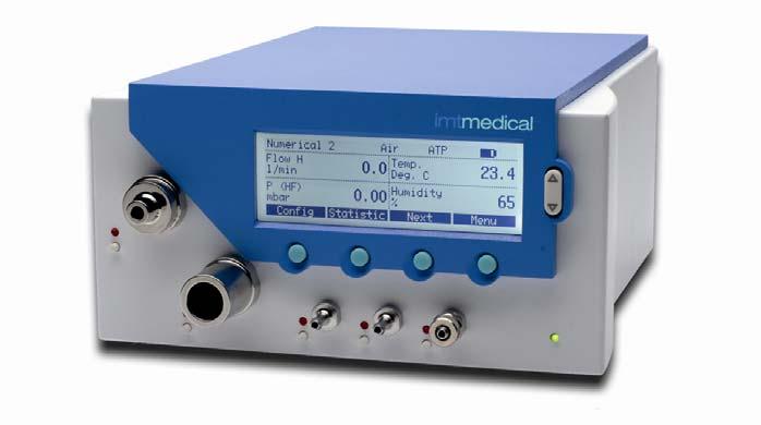
29 7.6 Numerical Display When you switch on the device Numerical 1 appears on the display. Four measured values can be displayed on the display at the same time. In the title bar you can see the current settings for the gas type, standard, battery status, mains mode and USB connection Specification for the Numerical Display (1) Numerical display number. Altogether there are four different numerical displays, allowing a maximum of 16 values to be displayed. (2) Trigger Indication. This icon indicates the detection of a trigger at the actual ventilation cycle. The icon is displayed for ½ second and indicates the start of a new inspiration. If this icon does not appear the trigger settings need to be adjusted (> 7.13 Setting the Volume Trigger). As long as there is no trigger event being detected, No Trig information is shown in the reading field. (3) Baseflow. This symbol appears if the baseflow function has been activated for volume measurement (> 7.13 Setting the Volume Trigger). (4) Gas type currently selected. Depending on what type of gas is being measured, the device must be set accordingly (> 7.12 Gas Type and Standard). (5) Standard. The values displayed will be calculated using the selected standards. Choose from several common gas standards (> 7.12 Gas Type and Standard). Version 2.1 Page 29 of 81
30 (6) Power supply. This symbol appears when the device is connected to the power supply. The analyzer can also be operated with the built-in battery. A battery symbol appears to indicate battery operation and loading status of battery: Battery full Battery empty Please recharge! A warning message appears if the battery gets very low (> 5.4 Battery Mode). (7) USB. The analyser can be connected to a PC via the USB connection. This symbol appears if a connection to the PC has been established. (8) Measured variable. Shows the variable. Variables can be changed in the configuration monitor (> Specification for the Configuration Display). (9) Unit of measurement. Shows the unit of the variable. Units can be changed in the configuration monitor (> Specification for the Configuration Display). (10) Config. Press the assigned key to reach the configuration display. Here you can change the variables and unit of measurement (> 7.7 Configuration Display). (11) Statistics. Press the assigned key to reach the statistics display, where you can view the minimum, maximum and average values for the individual variables (> 7.8 Statistics Display). (12) Reading. Shows the actual measured value. (13) Next. Use the assigned key to move between the four numerical displays. (14) Menu. Press the assigned key to reach the menu display. You can access the gas type, volume trigger, calibrations, language and system info from the menu. Page 30 of 81 Version 2.1

31 7.7 Configuration Display The numerical displays can be configured in the four configuration displays. Here you can change the variables and corresponding units of measurement for all four numerical displays Specification for the Configuration Display (1) Number of configuration display. You can switch between four different configuration displays. The number of the configuration display corresponds with the number of the numerical display. (2) The measured variable currently shown on the numerical display (> 15 Appendix B: Values and Units). You can highlight any value in the display by pressing the arrow keys. A red LED alerts you to the corresponding mechanical connection. (3) The unit of measurement used to for the variable in the numerical display (> 15 Appendix B: Values and Units). (4) Change. This key switches you to edit mode so that you can change the corresponding variable or unit of measurement. Press Save to save the new value. (5) Next. Use this key to switch from one of the four configuration displays to the next. (6) Numerical. Press this key to exit the configuration display. The numerical display returns. Version 2.1 Page 31 of 81
32 7.8 Statistics Display The four statistics displays show the current readings, minimum, maximum and mean values for the measured variables. The variables in the statistics display correspond with the variables in the numerical display Specification of the Statistics Display (1) Number of the statistics display. You can switch between four different statistics displays. The number of the statistics display corresponds with the number of the numerical display. (2) Measured variable. Shows the measured variable. Variables can be changed in the configuration monitor (> Specification for the Configuration Display). (3) Current reading. Shows the actual measured value using the same units as in the numerical display.. (4) Min. This value shows the lowest value measured since the last reset. (5) Max. This value shows the highest value measured since the last reset. (6) Mean. This value shows the arithmetic average of all values measured since the last reset. After one minute a moving average of one minute is displayed. (7) Reset. Press this key to reset the statistical values to zero. Simultaneously, all respiratory parameters will be set to no Tr. (8) Next. Use this key to switch from one of the four statistics displays to the next. (9) (10) Numerical. Press this key to exit the statistics display. The numerical display returns. Store. Press this key to save measurement parameters. In the statistic display the same units are being used as defined in the numeric display! Page 32 of 81 Version 2.1
 Calibrations.")
33 7.9 Menu Display The following parameters can be viewed and changed in the menu display: Calibrations Gas type and standard Volume trigger Language HW Activation System information Specification of the Menu Display (1) Calibrations. The oxygen sensor as well as all pressure and flow sensors and the MultiGasAnalyser TM OR-703 can be calibrated from this submenu. The offset calibration for pressure and flow can also be started by pressing the Zero! button. (2) Gas type/standard. The gas type and standard can be specified in this submenu. (3) The settings in the Trigger submenu are used to measure the respiratory values. By choosing different respiration modes standard triggers can be selected. (4) By selecting a Filter the displayed values of the Screen can be averaged over a certain time. (5) Language. Select the desired language here. (6) In the HW Activation submenu you can see if the USB port or the communication to the OR-703 multi gas sensor is enabled. If the FlowLab TM software or the integration of the gas sensor was ordered at a later date, you will need to enter a clearance code before a connection can be made. Version 2.1 Page 33 of 81
34 (7) System info contains information on the software and hardware versions, as well as data of the last factory calibration. Pressing the keys 2 and 3 simultaneously will hide all menu content that impacts the measurements. This avoids unwanted changes of the settings. (8) Factory Default button gives you the option or resetting your FlowAnalyser TM to the original delivery settings. (9) Back always brings you one level back. In this screen it will bring you to the numerical values. (10) Zero! Starts an offset calibration for the pressure and flow sensors. Attention: During this "fast calibration" no warnings are displayed and the screen will change at the end automatically to the numerical values. (11) Select. Press this key to open the selected submenu. (12) (13) Numerical. Press this key to exit the menu display. The numerical display returns. Data Storage. Measurement parameters can be saved and viewed. Page 34 of 81 Version 2.1
 2.")
35 7.10 Data Storage Capabilities 10 records each containing up to 16 measurement values can be stored directly on the FlowAnalyser. The selected gas standard and gas type are automatically stored in the data record Storing Data Step 1 1. Enter the Statistics display (>7.8 Statistics Display) 2. Press Store to save the displayed measurement values Step 2 1. Select the data no. you would like to store the measurement values under 2. Press Store Warning: If a record is already saved under the number you have selected, the new data will automatically replace the old data. Version 2.1 Page 35 of 81


36 Retrieving Data Step 1 1. Enter the Menu display and select Data Storage (>7.9 Menu Display) Step 2 1. Select the Data No. you would like to view 2. Press View Step 3 1. Scroll through the four pages of your selected data number by pressing Previous and Next. Once you have viewed all four pages of the selected data number, the first page of the next data number will automatically appear. Page 36 of 81 Version 2.1
37 Erasing Data Step 1 1. Enter the Menu display and select Data Storage (>7.9 Menu Display) Step 2 1. Under Action select Erase All Warning: If Erase All is selected all stored data will be automatically erased. Version 2.1 Page 37 of 81

38 7.11 Calibrations All the pressure and flow sensors, the oxygen sensor and the MultiGasAnalyser TM OR-703 can be calibrated in this submenu Calibrating the Pressure and Flow Sensors These calibrations are required if a value other than zero is displayed for differential pressure, high pressure or flow, although no connections have been made. This can happen during extreme fluctuations in temperature. Calibration will reset all values to zero. For a short time after turning on the instrument some displays may vary slightly from Zero until the optimal operating temperature is reached (10 to 15 Min). Therefore zero calibrations must not be performed, as long the instrument is cold. During a zero calibration it is important that no pressure or flow is applied to any connector! Attention: When performing the offset calibration using Zero! these warnings are not displayed on the display. Page 38 of 81 Version 2.1

39 Calibrating the Oxygen Sensor The oxygen sensor consists of an electrochemical cell and has to be recalibrated from time to time as a result of aging. When you start the calibration 100% oxygen and then ambient air must be applied, as instructed by the device. During both steps it is essential that enough of each gas flows through the main measuring channel for a sufficient duration. The calibration takes 75 seconds for each gas. The optimal flow is 20 to 30 l/min and may not be changed during the calibration process. If you make any changes to the measuring screen of the High flow or Low flow channel, flow measurement will have to be recalibrated. Recalibration can only be carried by the manufacturer or an authorized metrology station Calibrating the MultiGasAnalyser TM OR-703 Please refer to the special chapter regarding the MultiGasAnalyser TM OR-703 (>9 MultiGasAnalyserTM OR-703). Version 2.1 Page 39 of 81
40 7.12 Gas Type and Standard Depending on the gas to be measured, you will first have to set the appropriate gas type on the FlowAnalyser TM. Select from the following gas types: Air (100%) Air/O 2 -Man. (Air O 2 Mixture according to manual input. Standard value is 100% O 2 ) Air/O 2 Auto. (Air O 2 Mixture according to sensor reading of the internal Mixture cell). N 2 O/O 2 -Man.(Nitrous oxide O 2 Mixture according to manual input. Standard value is 100% O 2 ) N 2 O/O 2 -Auto.(Nitrous oxide-o 2 Mixture according to sensor reading of the internal Mixture cell) Heliox (21% O 2 ) He/O 2 -Man.(Helium-O 2 Mixture according to manual input. Standard value is 100% O 2 ) He/O 2 -Auto (Helium-O 2 Mixture according to sensor reading of the internal Mixture cell) N 2 O (100%) CO 2 (100%) Press Change to switch between the various options, and select the value with Save. When using O 2 -Man the O 2 Concentration can be changed in the same manner. Standard conditions are specific conditions for pressure, temperature and sometimes humidity as well, which form the basis for ascertaining the actual measured flow. It is therefore essential that you check precisely which standard condition the displayed value is based on! The currently selected standard is shown in the numerical display (> 5.2 Standard Conditions for Flow Measurement). If you press Change you will see a plus and minus, which you can use to switch between the different options. Select the value with Save. Selecting the wrong gas type or wrong gas standard can lead to measurement inaccuracies of up to 20%. Page 40 of 81 Version 2.1
.")
41 7.13 Setting the Volume Trigger Selection of Ventilation Mode Volume calculations are started and stopped by means of a trigger. The volume trigger can be set to start and stop according to flow or pressure in the High flow channel (> 10 Measuring Respiratory Coefficients). Over the selection of the ventilation mode you can adjust reasonable standard trigger values for each mode. Using these standard triggers 90% of all measuring tasks can be performed. You can choose out of the following Ventilation modes: Pediatric Ventilation (The flow measurement will be taken on the Low Flow Channel where as the pressure is measured on the connector for differential pressure Pdiff) Adult Ventilation (Measurements in the High Flow Channel.) High Frequency Ventilation (Measurements in the High Flow Channel.) Version 2.1 Page 41 of 81
42 Standard Trigger Each Ventilation Mode is related to a set of standard triggers. By pressing Reset you can always come back to these standards. Standard Trigger for Pediatric Ventilation: Attention: The measurements in the pediatric mode are taken in the Low Flow Channel. The appropriate pressure values have to be measured on the Pdiff connector. This is why the Pdiff has to be connected to the flow channel using a T-connector. If the trigger mode is set to pediatric, a pressure compensation for Low Flow Channel is activated automatically. Standard Trigger for Adult Ventilation: Standard Trigger for High Frequency Ventilation: Page 42 of 81 Version 2.1
43 Detailed Trigger Settings Flow channel. Here you can change the measuring (1) channel (HF = High Flow; LF = Low Flow). Further on you can decide whether the internal values (Flow or Pressure) are used to detect a trigger or whether an external trigger shall be used (> Usage of an External Volume Trigger). (2) Variable used for the start and stop triggers. You can select either pressure or flow in the High flow channel. (3) Trigger edge > Positive edge (rising curve) < Negative edge (falling curve) (4) Trigger level. If this level is passed, volume measurement will start or stop. The level must be in the range of lpm (HF channel) or lpm (LF channel) (5) Unit of measurement for the selected start and stop trigger variable. (6) Reset. Press the assigned reset key to load the default values for the volume trigger. Most volumes can be measured with these settings (> 10.3 Standard Trigger Values). (7) Baseflow. Here you can switch the baseflow on and off. The baseflow is a constant flow which should not be included in the calculation. If this function has been selected, a corresponding symbol appears in the display (> 7.6 Numerical Display). (8) Change. This key takes you to edit mode, where you can change the corresponding variable. (9) The Delay prevents that a single spot will release a trigger. If the appropriate trigger level is not maintained for the duration of the selected delay the trigger will not be accepted. High Frequency mode uses as standard a short delay! (10) Numerical. Press this key to exit the statistics display. The numerical display returns. Version 2.1 Page 43 of 81
 Reset. Press the assigned reset key to load the default values for the volume trigger.")
44 Usage of an External Volume Trigger (1) External. An external trigger signal is used to calculate the volume (> External Trigger). (2) Start. Specify whether volume measurement should take place upon a rising or falling edge in the signal. (3) Reset. Press the assigned reset key to load the default values for the volume trigger. Most volumes can be measured with these settings. (4) Baseflow. Here you can specify the baseflow. The baseflow is a constant flow which should not be included in the calculation. If this function has been selected, a corresponding symbol appears in the display (> 7.6 Numerical Display). (5) Change. This key takes you to edit mode, where you can change the corresponding variable. (6) The Delay prevents that a single spot will release a trigger. (7) Numerical. Press this key to exit the statistics display. The numerical display returns. Page 44 of 81 Version 2.1
45 7.14 Filter The display of the FlowAnalyser TM is updated every 500ms or in other words twice a second. The acquisition of new measuring values takes place every 5ms. Without using a filter the latest measured value will be displayed when updating the screen. Since each measurement is showing some noise it makes sense to average the values over a certain period of time. This is the meaning of the filter function. You can select one of the following filters: None (Display of the latest measured value without thresholds) Low (Mean value over 240ms) Medium (Mean value over 480ms) High (Mean value over 960ms) The standard filter is Medium. Press Change and scroll through the different filters using the arrow keys. Press Save to save the selected filter. The filter function does only impact the values displayed on the screen of the FlowAnalyser. The FlowLab TM Software does always show the raw, unfiltered values Setting the Language The display can be set to a number of languages. The available languages are continuously being revised and updated. Press Change and scroll through the different languages using the arrow keys. Press Save to save the selected value HW Activation In the submenu HW Activation you can see if the USB port or the communication to the MultiGasAnalyser TM OR-703 is enabled. If the FlowLab TM software or the integration of the gas sensor was added later, you will have to enter a clearance code, before you can use the optional feature. Version 2.1 Page 45 of 81


46 7.17 Accessing System Info 7.18 Invisible Menu Options To enter the code press Release. Various numbers then appear, which can be selected with the arrow keys. Using Change you can set each individual number to the correct value, and then save it with Save. Once all digits have been adjusted press Set PW to save the code. Enabled will appear on the screen if the code entered was correct. Please enter the code with right justification, and leave the remaining positions as 0. The following information can be found here: Software version Hardware version Date of last factory calibration Serial number of device In the System Info Menu it is possible to make invisible all menu options that contain settings which have an impact on the measurements. This avoids unwanted changes, e.g. when used in a production line. Press the keys 2 and 3 simultaneously while the System Info menu is active to make the options invisible. Enter System Info again and press the keys 2 and 3 simultaneously to get back all menu options visible. Page 46 of 81 Version 2.1

47 7.19 Factory Defaults The Factory Defaults setting allows you to re-set your FlowAnalyser TM settings to the delivered, neutral settings. Please note: the new settings can only be activated by turning off and re-starting your FlowAnalyser TM equipment. Version 2.1 Page 47 of 81

48 8 FlowLab TM Software 8.1 Installation Check that your computer meets all minimum requirements before installation (> 5.7 Minimum PC Requirements). Please observe the software instructions during the installation process. 8.2 USB Communication If your device was not configured to use FlowLab TM software in the factory, you will need to do this afterwards by entering a clearance code for the USB interface. This code can be obtained from your FlowAnalyser TM dealer (> 7.16 HW Activation). 8.3 Overview FlowLab TM software is divided into three areas: panels, numerics and trending. Select the required area from the icons on the lefthand side of the FlowLab TM window. The three areas will be described in the following chapters. 8.4 Options In the Tools / Options menu you can set the same settings as in Menu of the FlowAnalyser TM : Language, gas Standardisation, Gas type and volume Triggers. (> 7.9 Menu Display). Warning: Except of the language the device will adopt any changes that you make here to the FlowAnalyser! Additionally you can find the setting Performance where you can change the update rate for your monitor and the configuration area for Reports. (> 8.8 Reporting). Page 48 of 81 Version 2.1


49 8.5 Panels A maximum of 6 readings can be graphically displayed here. All related settings can be made in the Configuration menu Configuration Whenever you select a variable the corresponding mechanical connection is highlighted in the box on the right-hand side, and the range is shown below. Version 2.1 Page 49 of 81
 Title/Background color.")
50 (1) Value. Measured variable and its unit of measurement. (2) Grid. A grid can be displayed. (3) Line color and it's type can be chosen. (4) Curve type. The curve can be chosen in function of the time or as loop. For the display of a loop two values have to be selected, one for the x-axis and one for the y-axis. (5) Title/Background color. Each chart can here be identified by title. The back color of the chart can be changed. Page 50 of 81 Version 2.1

51 8.5.2 Curve Trigger The menu curve trigger is relates to the graphical display of the curves. If the curve shall be displayed as Norm- or Single Shot Curve, curve triggers are needed to start the display. Do not confuse this trigger with the volume trigger, which calculates volumes and respiratory coefficients (> 7.13 Setting the Volume Trigger) Version 2.1 Page 51 of 81

52 (1) Trigger source. Here you can choose the curve which shall be adjusted below. (2) Trigger type. Here you can choose the type of the trigger. This setting stays the same for all curves. There are three different types: Auto: This always displays the updated curve. No curve triggers are needed! Norm: This displays a static curve, which is updated with each new trigger. Single Shot: Use this function to capture a single curve. The trigger has to be activated manually. (3) Trigger level. The curve starts to be displayed when the measured value passes this level. (4) Pretrigger. If a certain period of the curve has to be displayed prior the effective trigger point this can be adjusted here. (5) Edge for the trigger Cursors If you wish to look at a curve in more detail, this can easily be done with the cursors provided. Altogether there are 4 different styles of cursor: Value Y Displays the Y value at the point where the cursor is intersected. Period Displays the time period between two cursors. Frequency Displays the frequency between two cursors. Peak - Peak Displays the Y value between two cursors Page 52 of 81 Version 2.1
 Curve.")
53 (1) Global Cursor. By choosing one of the 4 corresponding icons you can select a cursor to apply to all displayed curves in the corresponding style. (2) Individual Curser. It is also possible to apply a cursor only for one curve. If you right-click the cursor, a menu pops up where you can change the style of the cursor. (3) Curve. If two curves are displayed simultaneously in one panel, you can click the corresponding curve title to select the curve relating to the cursor. 8.6 Numerics In this area the data are numerically displayed. The statistical values for each variable can also be seen here, i.e. the mean value, and the smallest and largest value since the last reset. Further it s possible to check the tolerance of each measurement. If the measured value is fitting to the predefined accepted measurement range, the software will mark the value with: The general sensor variables are in the top section and the respiratory parameters in the bottom section. The overall appearance of the Numerics display can also be adjusted to individual requirements in the Configuration menu. In the columns Setpoint, Limit Lo and Limit Hi you can set the conditions for the automatic check of the measurements. Version 2.1 Page 53 of 81

54 8.7 Trending In this area measurements can be recorded within a specific time range. Select the Configuration menu to start a specific trending recording Configuration (1) In the field Measured Variables you can define the variables and units of measurement to be recorded. You can also select the color of the graphical display. The corresponding mechanical connection and possible measurement range can be found in the box at the top right-hand section of the display. (2) In the field Recording duration you can specify the length of the data recording. The range goes from 1 minute to 100 hours. (3) The field Recording interval defines how often data should be recorded. Select from a range of 0.1 seconds to 60 minutes. (4) In the field Memory resources you can check the expected file size and required working memory. (5) In the Time axis field you can select the unit of measurement which applies to the x-axis. (6) In the File name field you can specify the file name and storage location. Page 54 of 81 Version 2.1
 The section File enables you can to enter a title, which will be displayed above the trending curves.")
55 Depending on the recording time and interval very large files can be produced which can cause problems with the computer. Under normal circumstances we recommend a maximum file size of 1 MB. (7) The section File enables you can to enter a title, which will be displayed above the trending curves. Descriptive notes will be copied to the trending file but are not shown in the Display section Display (8) Once the Start button is pressed, the data are captured as defined and displayed online. Two files will be generated: The *.log file is containing all measurements and can be used by Excel or other data base systems. The *.cfg file contains the information for FlowLab TM to be able to reopen the trending files. You can follow the data acquisition in the Display menu. In the Display view the curves can be visualized and analyzed. You can use the same zooming functions and cursors as with the Panels. By pressing load trend you can load another trending file which has been produced earlier. Version 2.1 Page 55 of 81
 In the Reporting Options area you can select whether numerical data and/or curves shall be printed in the report.")
56 8.8 Reporting The reporting function is to print out your measurements in a sheet which includes the measured numerical data, the curves, the company s data and descriptions Configuration In the Configuration menu you can configure all heather information of the reports as well as what shall be printed on the report (1) In the Reporting Options area you can select whether numerical data and/or curves shall be printed in the report. (2) In the Test Equipment area you see all information regarding the connected FlowAnalyser TM. The data is automatically loaded from the device. (3) In the Test Center field you can edit the company s data and there is also the possibility to load your company s logo to be shown in the report. (4) Use the Test Object area to edit the information about the test object, such as place of test, tested instrument or serial number of the instrument under test. Further you can define to print a unique ID number in the footer of the report. (5) With the Preview Actual Data Report button an actual data report can be produced, which displays the actual numerical data and curves. Page 56 of 81 Version 2.1

57 On the preview screen you have access to the printing options as well as to page layout and save settings options. Version 2.1 Page 57 of 81


 Total gas mixture Balance Gas (The")
58 8.9 Gas Calculator The gas calculator enables users to configure a mixture of varying gas fractions for flow and volume measurements. Users can select the ratio of standard gases as well as the ratio and physical characteristics of customized gases (1) (2) (3) (4) (5) Customized gases (user-defined) Ratio of the total gas volume Physical characteristics (entered by the user) Total gas mixture Balance Gas (The ratio of the balance gas is automatically calculated. The sum of the ratios must be 100%.) Page 58 of 81 Version 2.1
59 8.10 FlowLab TM Settings In the header toolbar menu listing under File the Load FlowLab Settings and Save FlowLab Settings options allows users to save and load user-defined settings. The following settings can be saved using this important menu function: - Panels - Numerics - Trending - Reports The settings are then saved as an *.ini File. Version 2.1 Page 59 of 81
60 9 MultiGasAnalyser TM OR Description The MultiGasAnalyser TM OR-703 head comprises a stateof-the-art ten-channel non-dispersive infrared (NDIR) gas bench, a barometric pressure sensor, a power regulator, a CPU and an RS-232 digital interface. The sensor measures concentrations of Carbon dioxide Dioxide (CO 2 ), Nitrous oxide Oxide (N 2 O), Halothane (HAL), Enflurane (ENF), Isoflurane (ISO), Sevoflurane (SEV), Desflurane (DES) At the same time you can measure CO 2, N 2 O and one of the five narcotic agents. 9.2 Intended use The MultiGasAnalyser TM OR-703 is intended to be connected to the FlowAnalyser TM for gas measurements in order to calibrate or test anaesthetic systems. It is not intended to be used in means of monitoring a patient. It is not intended to be used in outdoor transport applications, such as in cars or in aircrafts. 9.3 Warnings The MultiGasAnalyser TM OR-703 is intended for use by professionally trained personnel only. The MultiGasAnalyser TM OR-703 must not be used with flammable anaesthetic agents. Used disposable airway adapters shall be disposed of in accordance with local regulations for contaminated and biologically fluids. Measurements can be affected by mobile and RF communications equipment. It should be assured that the MultiGasAnalyser is used in the electromagnetic environment specified. Page 60 of 81 Version 2.1


61 9.4 Design and theory The MultiGasAnalyser TM OR-703 consists of an OR-sensor head (1), an oxygen sensor cell (optional) (2) an airway adapter (3) and an adapting cable (4). The OR sensor head snaps in place on the top of the airway adapter that includes the optical components for measuring all gases. As all necessary calibration constants are stored within each sensor head, the probes can be replaced without the need for recalibration. The measurement of CO 2, N 2 O and anaesthetic agents in the gas mixture is based on the fact that the different gas components absorb infrared light at specific wavelengths. The gas measurements are obtained by continuously measuring the infrared gas absorption in the gas flow through the adapter. To measure the concentrations and identify the gases, absorption of up to ten different wavelengths of infrared light is measured. Version 2.1 Page 61 of 81


62 9.5 How to connect Plug the OR sensor via adapter cable into the RS-232 input of the FlowAnalyser TM and switch the power on. Only use the adapter cable provided by imtmedical ag. Snap the OR sensor head on top of the OR airway adapter. It will click into place when properly seated. Wait for 15 Minutes until measurements are taken, the sensor needs to warm up. A green LED indicates that the OR sensor is ready for use. The above message will appear to show that connection has been established successfully. By selecting Details all technical information regarding the sensor will be displayed. Page 62 of 81 Version 2.1
63 Always position the OR-sensor with the LED pointing upwards. Place the MultiGasAnalyser TM between gas source and FlowAnalyser TM. According to flow direction through FlowAnalyser TM the MultiGasAnalyser TM can be connected on front or back airway connector of FlowAnalyser TM. 9.6 LED Signal The LED situated on the MultiGasAnalyser TM OR-703 sensor head is used to signal the following conditions: Steady green light Steady blue light Steady red light Blinking red light System OK Anesthetic agent present Sensor error Check adapter 9.7 Calibration of Sensor head A room air calibration of the IR measurement should be performed at regular intervals as well as after replacing the airway adapter. The need for a room air calibration is indicated by the permanent alarm message Room air calibration of OR required! being displayed on the monitor (message disappears after calibration). Room air calibration may also be performed if an offset in gas readings should be discovered when verifying gas readings with a reference instrument. The calibration is performed by snapping a new OR airway adapter onto the OR sensor, without connecting the airway adapter to the airway circuit, and then start the calibration procedure in the menu options of the FlowAnalyser TM (> Calibrating the MultiGasAnalyser TM OR-703). It will click into place when properly seated. Wait for 15 Minutes before continuing, the sensor needs to warm up. Version 2.1 Page 63 of 81
 in the OR airway adapter is of crucial importance for a successful room air calibration.")

64 When replacing the airway adapter, a zero calibration must be performed. Special care should be taken to avoid breathing into the adapter during the calibration procedure. The presence of ambient air (21% O 2 and 0% CO 2 ) in the OR airway adapter is of crucial importance for a successful room air calibration. Always perform a pre-use check after performing a calibration. 9.8 Preventive maintenance The sensor can be cleaned using a cloth moistened with ethanol or isopropyl alcohol. Gas readings should be verified at regular intervals with a reference instrument. imtmedical ag is offering a service for recertification the measurements of the sensor. Page 64 of 81 Version 2.1
65 9.9 Specifications MultiGasAnalyser TM OR-703 Physical Data Dimensions (W x D x H) 37 x 27 x 25 mm 1.45 x 1.1 x 0.9 inches Weight <30 g (cable excluded) Cable length 2.50 m ±0.02 Environmental Data Operating temperature C, F Storage temperature Operating humidity Storage humidity Operating atmospheric pressure C, F 10 95% RH, non-condensing 5 100% RH, condensing hpa (700 hpa corresponding to an altitude of 3048 m) Accuracy specifications Gas Range Inaccuracy CO % ±8 % of reading or ±0.3 % ABS N 2 O 0 100% ±8 % of reading or ±2 % ABS HAL, ISO, ENF 0 5% ±8 % of reading or ±0.15 % ABS SEV 0-8% ±8 % of reading or ±0.15 % ABS DES 0 18% ±8 % of reading or ±0.15 % ABS Rise time (@ 10 l/min) Monitoring CO 2 < 60 ms N 2 O, Hal, Iso, Enf, Sev, Des < 150ms Numerical Data and Real-time Waveform with FlowLab TM Software Version 2.1 Page 65 of 81
66 10 Measuring Respiratory Coefficients 10.1 General To be able to measure respiratory coefficients the FlowAnalyser TM has to be able to pick out a respiratory cycle from the pressure and/or flow curves. The triggers are controlling this. V & Breath Cycle Inspiration Expiration Start Trigger S E S V & 0 End Trigger It is therefore essential that the start and stop triggers are correctly defined, as they have a significant effect on the resulting measurements. General volume triggers are used to trigger a respiratory cycle (> 7.13 Setting the Volume Trigger). It is therefore very important that the volume triggers are set correctly before starting to measure the respiratory coefficients. t The start trigger is defined as the start of the inspiration phase. The stop trigger is defined as the end of the inspiration phase and start of the expiration phase. Expiration continues until the next start trigger appears. Page 66 of 81 Version 2.1
67 10.2 Connection to the Ventilator There are three different ways to connect the FlowAnalyser TM to the ventilator: A. After the Y-piece PF-30X Ventilator Test lung B. In the inspiration channel before the Y-piece PF-30X Ventilator Test lung C. In the expiration channel before the Y-piece Ventilator PF-30X Test lung 10.3 Standard Trigger Values As the FlowAnalyser TM can measure flows in both directions, connection A would seem to be the best option. With this configuration the flow is usually selected as trigger variable. The standard trigger values for the flow trigger are: Start trigger: Flow > 3 l/min End trigger: Flow < -3 l/min Further standard triggers you will find in the chapter Operation: (> Standard Trigger) Pressure is usually used as the trigger signal for connections B and C. In this case the standard values are as follows: Start trigger: Pressure > 1 mbar End trigger: Pressure < 1 mbar Version 2.1 Page 67 of 81

68 10.4 Baseflow Baseflow refers to a constant base flow that is not included in the volume calculation. For example, if there is a definite leak in the system, which constantly loses 3 l/min air, these 3 l/min are not part of the inspiration volume. By entering Baseflow: On 3.0 l/min The volume calculation can be corrected for this example Finding the Correct Trigger Values The first time you have to set a trigger you need to know the curve pattern of the signal used for the trigger (flow or pressure). We therefore advise that you observe this curve first with the FlowLab TM software. On the graph it is then very easy to see where the triggers should be set. Below are a few examples to illustrate possible problems Flow curve after Y- Piece This example shows a normal flow curve. Standard triggers (> 3 l/min / < -3 l/min) can be used here without any difficulty. In this situation you must ensure that the trigger is set well above the noise in the base line, as this may trigger false readings. Page 68 of 81 Version 2.1

69 Flow curve before Y- Piece False Trigger! This curve shows the flow curve in the inspiration channel before the Y-piece. The first two circles mark the triggers that should be used here. The figure above shows another little false signal at this measuring point after inspiration. This was due to the valves switching over and caused a false trigger! Warning: Flow may not be used as the trigger in this instance the pressure curve should be used (> Pressure curve before Y-Piece). Version 2.1 Page 69 of 81

70 Pressure curve before Y-Piece The standard triggers can again be used for the pressure curve: (> 1 mbar / < 1 mbar). However, please ensure here as well that the trigger is set well above the noise of the base line. If not the value must be raised. Please note that it is very easy to work out where the trigger should be set by using the cursor in the FlowLab TM software (>8.5.3 Cursors) Special situations The use of a standard trigger threshold enables the acquisition of very good calculated data, usually of higher accuracy than the ones calculated by today s ventilators. More accurate calculated data may indeed be obtained by setting different trigger thresholds. If the values of the FlowAnalyser TM have to be compared to the values of a ventilator it is important to know exactly how the requested value is measured or calculated in the ventilator. Page 70 of 81 Version 2.1
71 Inspiration Volume Vti When the ventilation cycle reaches a plateau or a pause, the inspiration flow is technically zero, however, a very small flow could remain and be measured and integrated. Most current ventilators do not count this flow into the volume calculation. By adapting the trigger settings as described below, one can set the FlowAnalyser TM to disregard these measurements: V & Breath Cycle Inspiration Expiration Vti Start and End Trigger E V & 0 S S t Expiration Volume Vte A similar situation could arise while measuring Vte: V & Breath Cycle Inspiration Expiration Vte Start Trigger S S V & 0 End Trigger E t Version 2.1 Page 71 of 81
72 11 Care and Maintenance 11.1 Guidelines for Care and Maintenance Maintenance work must be carried out with care and according to regulations to ensure that the FlowAnalyser TM functions safely and effectively. Only use manufacturer's recommended parts (>12.4 Spare Parts). Guidelines and maintenance tips provided by the individual manufacturers must be explicitly followed Notes on Replacing Components The maintenance work listed below should only be carried out by experienced personnel who are familiar with the FlowAnalyser TM. All other repairs and service should only be carried out by trained personnel. Always refer to the individual manufacturer's instructions Preventative Cleaning and Maintenance Routines To guarantee the maximum long-term precision and reliability of your device, the following maintenance routines must be carried out at regular intervals: During operation: Always use the protection filter on both channels. Every four weeks Check the protection filter for permeability. This has to be measured as a pressure drop across the filter. Install a T- connector on each input and output of the filter and connect each to the differential pressure port while applying a flow of 60 l/min. The filter must be changed if the pressure drop is greater than 2 mbar. Every 12 months: Factory calibration to ensure accurate and reliable measuring. Page 72 of 81 Version 2.1


73 Replacing the Measuring Screen Replacing the Oxygen Sensor When the measuring screens are replaced flow measurement will require subsequent recalibration. This can only be carried out by the manufacturer or authorized metrology laboratories. To replace the oxygen sensor the lid must be removed: 1 2 Using an appropriate tool release screws 1 and 2 which hold the lid on. Push the lid carefully forward. Lift the cover up. The oxygen sensor is located inside the analyzer. 1. Remove the plug from the oxygen sensor. 2. Take out the oxygen sensor by turning counter clockwise. 3. Turn the new oxygen sensor clockwise to insert it into the block and reconnect the plug. Version 2.1 Page 73 of 81


74 4. Replace the lid. 5. Calibrate O 2 Sensor (> Calibrating the Oxygen Sensor) Replacing the Fuses To replace the fuses you need to remove the back plate: Using an appropriate tool release screws 1-6 which hold the back plate on. 5 6 Pull the back plate off. Both fuses are located on the printed circuit board inside the FlowAnalyser TM. 1. Unplug the battery. 2. Remove the faulty fuse. 3. Insert the new fuse. Page 74 of 81 Version 2.1
81 750 66 99 Fax: +41 (0)81 750 66 95 E-Mail: sales@imtmedical.")
75 F2 F1 (F1) (F2) 1.25 A F (external feed 18V) 1.25 A F (internal feed 12V) Only use manufacturer's recommended parts (>12 Accessories and Spare Parts). 4. Replace the back plate Contacts Please direct any queries or problems to one of the addresses below Manufacturer's imtmedical ag Address Gewerbestrasse 8 CH-9470 Buchs Switzerland Tel: +41 (0) Fax: +41 (0) sales@imtmedical.com Technical Support Tel: +41 (0) Fax: +41 (0) techsupport@imtmedical.com Version 2.1 Page 75 of 81
BENCHTOP FLOW ANALYZER
 BENCHTOP FLOW ANALYZER PFC-3000 SERIES USER MANUAL NOTICE DISCLAIMER USER ASSUMES FULL RESPONSIBILITY FOR UNAUTHORIZED EQUIPMENT MODIFICATIONS OR APPLICATION OF EQUIPMENT OUTSIDE OF THE PUBLISHED INTENDED
1 Content. 7 Operation Switching the Device On and Off The Start Screen Adjusting the Contrast... 26
 Innovating Together RIGEL VENTEST 8XX ventilator tester Copyright 2015 SEAWARD GROUP Last Update: 15th October 2015 Instruction Manual 800A550 Revision 1.0 1 Content 1 Content... 1 2 Preface... 4 3 Intended
CITREX H4 Mobile gas flow analyser. The ideal mobile device for flow and pressure analysing.»
 CITREX H4 Mobile gas flow analyser «The ideal mobile device for flow and pressure analysing.» Ventilator tester for mobile use CITREX is designed for mobile and easy use while still meeting all requirements
Panther 5 Acute Care Ventilator
 1 HIGHLIGHTS High performance and advanced features target the ICU environment Utilizes an internal blower with a specially designed flow control valve removing the need for using compressed air without
VT650. Gas Flow Analyzer. Technical data. Key benefits and features:
 VT650 Gas Flow Analyzer Technical data Accurately test gas flow equipment including ventilators with the all-in-one, portable Fluke Biomedical VT650 Gas Flow Analyzer. Accurate The VT650 Gas Flow Analyzer
VT900. Gas Flow Analyzer. Technical data. Key benefits and features:
 VT900 Gas Flow Analyzer Technical data The Fluke Biomedical VT900 is designed to accurately and reliably test all types of medical gas flow equipment ventilators, insufflators, oxygen meters especially
RM-80 respiration monitor
 RM-80 respiration monitor User Manual September 18, 2015 0025-003M 950 North Hague Avenue Columbus, Ohio 43204-2121 USA Sales: sales@colinst.com Service: service@colinst.com Phone: (614) 276-0861 Fax:
Pegas 4000 MF Gas Mixer InstructionManual Columbus Instruments
 Pegas 4000 MF Gas Mixer InstructionManual Contents I Table of Contents Foreword Part I Introduction 1 2 1 System overview... 2 2 Specifications... 3 Part II Installation 4 1 Rear panel connections...
VT900A + VAPOR. Technical data. One Solution. Auto-detection to Ensure Patient Safety. Key benefits and features
 Technical data VT900A + VAPOR The Fluke Biomedical VT900A + VAPOR is designed to efficiently and reliably perform a full anesthesia machine PM, from ventilators to vaporizers. One Solution VT900A + VAPOR
Pneumatic high-pressure controller Model CPC7000
 Calibration technology Pneumatic high-pressure controller Model CPC7000 WIKA data sheet CT 27.63 Applications Healthcare and avionics industry Industry (laboratory, workshop and production) Transmitter
Multi-Gas Analyzer. Multi-Gas Analyzer bcgroupintl.com. Features - MGA MGA-3050 Multi-Gas Analyzer
 65 Multi-Gas Analyzer Multi-Gas Analyzer Features - MGA-3050 ± Displays anesthetic agent output in percentage values ± Easy-to-use ± Fast response time ± Very compact ± Connects directly to common gas
OxyScan Graphic. Operating Instructions. UMS Micro-oxygen sensor 501. Microprocessor instrument
 OxyScan Graphic Operating Instructions UMS Micro-oxygen sensor 501 Microprocessor instrument Introduction Thank you for choosing the UMS Micro Oxygen Sensor 501 - a highly advanced product! Please read
The HumiSys. RH Generator. Operation. Applications. Designed, built, and supported by InstruQuest Inc.
 The HumiSys RH Generator Designed, built, and supported by InstruQuest Inc. Versatile Relative Humidity Generation and Multi-Sensor System The new HumiSys with single or dual RH probes capabilities is
PTS 2000Version User s Manual. Operators Manual
 PTS 2000Version 4.0.. User s Manual Operators Manual ... Copyright Puritan-Bennett Corporation 1999, 2003. All rights reserved. The information contained in this manual is the sole property of Puritan
HumiSys HF High Flow RH Generator
 HumiSys HF High Flow RH Generator Designed, built, and supported by InstruQuest Inc. Versatile Relative Humidity Generation and Multi-Sensor System The HumiSys HF is a high flow version of the previously
973-SF 6 Analyzer. Precise and Stable SF 6 Gas Analyzer REFLECTING YOUR STANDARDS
 Precise and Stable SF 6 Gas Analyzer Simultaneous measurement of humidity, SF 6 purity and SO 2 concentration Integrated gas recovery system with automatic pump back Fully automated SF 6 gas testing Fundamental
HUMOR 20. High-precision Humidity Calibrator HUMOR 20. Operation
 High-precision Humidity Calibrator The role of humidity calibrations that are accurate, reproducible, and documentable is becoming more and more important. ISO quality guidelines and regulations according
FTC130 Transmitter. Operating Manual
 Seite 1 von 11 FTC130 Transmitter Fast Thermal Conductivity Analyzer Operating Manual 1.09KD180724CWI1V05 Messkonzept GmbH Seite 2 von 11 1. Intended Use... 3 2. Description... 4 3. Measuring gases and
Oxygen Meter User Manual
 Oxygen Meter User Manual Monday, July 23, 2007 1. Outline...2 2. Program...3 2.1. Environment for program execution...3 2.2. Installation...3 2.3. Un installation...3 2.4. USB driver installation...3 2.5.
Pneumatic high-pressure controller Model CPC7000
 Calibration technology Pneumatic high-pressure controller Model CPC7000 WIKA data sheet CT 27.63 Applications Automotive and avionics industry Industry (laboratory, workshop and production) Transmitter
VENTIlogic LS VENTIlogic plus. 100 % Mobility and Reliability in IV and NIV
 VENTIlogic LS VENTIlogic plus 100 % Mobility and Reliability in IV and NIV VENTIlogic LS VENTIlogic plus Your requirements for reliability and mobility are our benchmark. VENTIlogic LS and VENTIlogic plus
Technology. In the My Files [My Files] submenu you can store all the programs that you have made on the NXT or downloaded from your computer.
![Technology. In the My Files [My Files] submenu you can store all the programs that you have made on the NXT or downloaded from your computer.](/thumbs/74/70002303.jpg "Technology. In the My Files [My Files] submenu you can store all the programs that you have made on the NXT or downloaded from your computer.") NXT Main Menu My Files Files are automatically placed into the appropriate folders. When you download a program using a Sound file to the NXT, the program will be placed under Software files while the
NXT Main Menu My Files Files are automatically placed into the appropriate folders. When you download a program using a Sound file to the NXT, the program will be placed under Software files while the
Oxylog 3000 plus Emergency & Transport Ventilation
 Oxylog 3000 plus Emergency & Transport Ventilation Offering high ventilation performance with features such as AutoFlow, integrated capnography and non-invasive Ventilation, the compact and robust Oxylog
Mass Flowmeters. Mass Flowmeters for Gases
 Mass Flowmeters Mass Flowmeters for Gases Fast, Accurate, Low Pressure Drop for critical measurement applications! Flow (Std l/min) Response to a step change in flowrate 300 200 100 4 Milliseconds 63%
Servo UNIVERSAL ADVANCED VENTILATION PLATFORM ALL PATIENT CATEGORIES
 DATA ADVANCED VENTILATION PLATFORM ALL PATIENT CATEGORIES CRITICAL CARE HIGHLIGHTS! For all patient categories, from neonate and pediatric to adult! A platform for the future choose the level of system
HUMOR 20. High Accuracy Humidity Calibrator. Water T, p1 HUMOR 20 V1.0
 High Accuracy Humidity Calibrator The role of humidity calibrations that are accurate, reproducible, and documentable is becoming more and more important. ISO quality guidelines and regulations according
CONSOLE-320 ENGLISH. 230A: CONSOLE-320 with cable data output Item 230B: CONSOLE-320 with cable + wireless radio data output
 CONSOLE-320 Item 230A: CONSOLE-320 with cable data output Item 230B: CONSOLE-320 with cable + wireless radio data output Table of contents 1. INTRODUCTION...2 1.1 Power supply...2 1.2 Connections...2 1.3
Mass Flow Controller (MFC) for Gases
 for Gases") Mass Flow Controller (MFC) for Gases Type 8713 can be combined with... Direct flow measurement by MEMS- Technology for nominal flow rates from 1 ml N /min to 8 l N /min (N 2 ) High accuracy and repeatability
Mass Flow Controller (MFC) for Gases Type 8713 can be combined with... Direct flow measurement by MEMS- Technology for nominal flow rates from 1 ml N /min to 8 l N /min (N 2 ) High accuracy and repeatability
VENTIlogic LS VENTIlogic plus. 100 % Mobility and Reliability in IV and NIV
 VENTIlogic LS VENTIlogic plus 100 % Mobility and Reliability in IV and NIV VENTIlogic VENTIlog LS Your Requirements for Reliability and Mobility are Our Benchmark. VENTIlogic LS and VENTIlogic plus are
Operating Manual. BACVis. Manual BACVis. for. Sensors and MilliGascounter. Rev
 Operating Manual BACVis Manual BACVis for Sensors and MilliGascounter Rev.150728001 Contents 1 ABOUT THIS DOCUMENT... 2 1.1 Function... 2 1.2 Target group... 2 1.3 Symbols used... 2 2 SYSTEM REQUIREMENTS...
SLE4000. Infant Ventilator with touch-screen operation. When the smallest thing matters
 SLE4000 Infant Ventilator with touch-screen operation When the smallest thing matters SLE4000 - The Total Solution for Conventional Infant Ventilation SLE is a world leader in the design and manufacture
OXY Integral. INTERCON ENTERPRISES INC Tel: Fax: Internet:
 OXY Integral INTERCON ENTERPRISES INC Tel: 800 665 6655 Fax: 604 946 5340 E-Mail: sales@intercononline.com Internet: www.intercononline.com Manual Integral 2006 1 INDEX 2-3 PREFACE 4 INTRODUCTION 5 Principle
UNDERSTANDING, ACCELERATED
 UNDERSTANDING, ACCELERATED MEASURE FLOW, PRESSURE, AND TEMPERATURE ALL IN ONE INSTRUMENT! Designed for Performance TSI thermal mass flowmeters incorporate a proprietary platinum film sensor design for
Precision digital pressure gauge Model CPG1000
 Calibration technology Precision digital pressure gauge Model CPG1000 WIKA data sheet CT 10.01 Applications Oil and gas industry Maintenance and service facilities Calibration service companies and service
GA-300 Gas Analyzer. Technical Note. Overview. Front Panel. iworx Systems, Inc. GA-300
 Technical Note GA-300 Overview The GA-300 CO2 and O2 Gas Analyzer is easy to use, robust, and adaptable to human, animal, and plant applications. The GA-300 has two analog outputs to allow recording and
DATA SHEET. VENTILATION SERVO-s
 DATA SHEET VENTILATION The Gold Standard Critical Care 3 PROVEN SERVO SIMPLICITY, RELIABILITY AND SENSITIVITY MAQUET THE GOLD STANDARD Leading the way: MAQUET is a premier international provider of medical
EPP4 Pressure Regulator Basic G 1/4"
 EPP4 Pressure Regulator Basic G 1/4" Flow Curve 1/4" Dimensions Outlet pressure - bar 9 8 7 6 5 4 3 2 1 0 0 20 40 60 70 80 100 120 Flow rate - Nm 3 /h The male connector adopted on the EPP4 is a standard
Helium Level Measurement Unit
 Helium Level Measurement Unit HLMU User Manual Version 002 The information in this manual may be altered without notice. BRUKER BIOSPIN accepts no responsibility for actions taken as a result of use of
Overview. Front Panel: Keypad and Display
 Overview The GA-200B is an analyzer that integrates a gas sampling system with sensors to measure and display the concentrations of oxygen and carbon dioxide in a sample as the percentage of a gas in the
Experiment AMe-1: Small Animal Respiratory Exchange Ratio (RER)
") Experiment AMe-1: Small Animal Respiratory Exchange Ratio (RER) Background There are two main sources of energy available for animal metabolism: carbohydrates (CHO) and fats. These molecules are broken
Experiment AMe-1: Small Animal Respiratory Exchange Ratio (RER) Background There are two main sources of energy available for animal metabolism: carbohydrates (CHO) and fats. These molecules are broken
Hand-held pressure calibrator with integrated pump Model CPH6600
 Calibration technology Hand-held pressure calibrator with integrated pump Model CPH6600 WIKA data sheet CT 16.01 Applications Calibration service companies and service industry Measurement and control
Pressure Automated Calibration Equipment
 GE Measurement & control Pressure Automated Calibration Equipment Safety Instructions and User Guide - K0447 PACE5000 PACE6000 K0447 Issue No. 9 1 10 1 PACE5000 1 2 3 4 5 PACE6000 2 6 7 8 3 4 5 6 7 8 9
Calibration Gas Instrument INSTRUCTION MANUAL. Release I. Advanced Calibration Designs, Inc.
 Advanced Calibration Designs, Inc. Calibration Gas Instrument INSTRUCTION MANUAL Release I www.goacd.com Instruction Manual Gas Generator Release I TABLE OF CONTENTS I. General Description Page 2 II. Start-Up
WF STEUERUNGSTECHNIK GMBH. INFORMATION and TECNICAL DESCRIPTION
 1 INFORMATION and TECNICAL DESCRIPTION 14 2 AIRLEADER Professional Compressor Management + Compressed Air Visualisation + Alarm Service Management + AIRLEADER - has been the effective answer for compressed
PGA3510 Portable 3-Gas IR Analyzer. Operations Manual
 PGA3510 Portable 3-Gas IR Analyzer Operations Manual Please read, understand, and follow these instructions before operating this equipment. Super Systems, Inc. is not responsible for damages incurred
User's Manual. Heavy Duty Dissolved Oxygen Meter. Model
 User's Manual Heavy Duty Dissolved Oxygen Meter Model 407510 Introduction Congratulations on your purchase of Extech's Heavy Duty Dissolved Oxygen / Temperature Meter which simultaneously displays Dissolved
GAS ANALYSER OXYBABY 6.0 for O 2. or O 2 /CO 2
 GAS ANALYSER OXYBABY 6.0 for or Cordless hand held oxygen or combined oxygen and carbon dioxide analyser for checking modified atmospheres in food packs. The ideal instrument for portable, faster and accurate
Operating Manual. SUPREMA Calibration. Software for Fire and Gas Warning Units. Order No.: /01. MSAsafety.com
 Operating Manual Software for Fire and Gas Warning Units Order No.: 10154656/01 MSAsafety.com MSA Europe GmbH Schlüsselstrasse 12 8645 Rapperswil-Jona Switzerland info.ch@msasafety.com www.msasafety.com
Instruction Manual. BZ7002 Calibration Software BE
 Instruction Manual BZ7002 Calibration Software BE6034-12 Index _ Index Index... 2 Chapter 1 BZ7002 Calibration Software... 4 1. Introduction... 5 Chapter 2 Installation of the BZ7002... 6 2. Installation
MEGAS 2.0. Gas analysis with direct C-Level Calculation and Bus-Connection. Data sheet
 Data sheet MEGAS 2.0 Gas analysis with direct C-Level Calculation and Bus-Connection Mesa Industrie-Elektronik GmbH Neckarstraße 19, D-45768 Marl info@mesa-gmbh.de +49 (0) 2365-97 45 1-0 +49 (0) 2365-97
HUMOR 20 HUMOR 20. High-precision Humidity Calibrator. Water T, p1
 High-precision Humidity Calibrator The role of humidity calibrations that are accurate, reproducible, and documentable is becoming more and more important. ISO quality guidelines and regulations according
Mass Flow Controller (MFC) for Gases
 for Gases") Mass Flow Controller (MFC) for Gases Bypass MFC with capillary technology for nominal flow rates from 5 ml N /min to 15 l N /min Applicable for aggressive gases Compact design and digital communication
Mass Flow Controller (MFC) for Gases Bypass MFC with capillary technology for nominal flow rates from 5 ml N /min to 15 l N /min Applicable for aggressive gases Compact design and digital communication
1. Foreword. Scope This documentation is valid for the product named: CITREX You will find the name CITREX on the bottom of the casing of the device.
 User Manual 10.14 2 / 65 Contents 1. Foreword...4 2. Intended use...5 3. Safety instructions...6 4. Technical specifications...8 5. Start up... 17 6. Operation... 24 7. Connecting up the device... 33 8.
Mass Flow Meter (MFM) for Gases
 for Gases") 873 Mass Flow Meter (MFM) for Gases Direct flow measurement by MEMS- Technology for nominal flow rates from 1 ml N /min to 8 l N /min (N 2 ) High accuracy Short response time Compact design and digital
873 Mass Flow Meter (MFM) for Gases Direct flow measurement by MEMS- Technology for nominal flow rates from 1 ml N /min to 8 l N /min (N 2 ) High accuracy Short response time Compact design and digital
Oxylog VE300 Emergency & Transport Ventilation
 Oxylog VE300 Emergency & Transport Ventilation The straightforward and user-friendly Dräger Oxylog VE300 is built to face your challenges in preclinical emergency services With reliable ventilation technology,
Airox Supportair Ventilator
 Airox Supportair Ventilator A versatile hospital ventilator with a titration platform that enables a smooth transition to the patient s home care ventilator Titration Platform The Supportair ventilator
Technical Information Conducal CLY421
 TI00496C/07/EN/01.12 71142150 Products Solutions Services Technical Information Conducal CLY421 Conductivity calibration set for ultrapure water applications Factory calibrated measurement box Certified
User Manual PTW-DensiX. D / Di/Zi
 User Manual PTW-DensiX D148.131.0/3 2005-05 Di/Zi General Information General Information The product bears the CE-mark "CE-0124" in accordance with the Council Directive 93/42/EEC about Medical Devices
Operating manual. Oxi 3205 O mg/l C. [Sal] Dissolved oxygen (D.O.) meter
![Operating manual. Oxi 3205 O mg/l C. [Sal] Dissolved oxygen (D.O.) meter](/thumbs/83/87153656.jpg "Operating manual. Oxi 3205 O mg/l C. [Sal] Dissolved oxygen (D.O.) meter") O 2 Operating manual Oxi 3205 [Sal] 7.92 25.0 mg/l C 3205 Dissolved oxygen (D.O.) meter ba75797e03 09/2011 Oxi 3205 Accuracy when going to press The use of advanced technology and the high quality standard
O 2 Operating manual Oxi 3205 [Sal] 7.92 25.0 mg/l C 3205 Dissolved oxygen (D.O.) meter ba75797e03 09/2011 Oxi 3205 Accuracy when going to press The use of advanced technology and the high quality standard
SATURN EVO COLOR A N A E S T H E S I A S Y S T E M. Manufacturer of high quality anaesthesia products
 Saturn Evo SATURN EVO COLOR A N A E S T H E S I A S Y S T E M i n t e l l i g e n t s i m p l i c i t y Manufacturer of high quality anaesthesia products SATURN EVO COLOR PATIENT SAFETY AND USER PATIENT
Digital Melting Point Apparatus
 Digital Melting Point Apparatus Heating Plateau Ramping Start/Stop Plateau set Ramp stop Hold User Guide Version 1.1 Heating Viewing tube Sample Chamber IEC power inlet socket Power on/off Temperature
Operating instructions for. For visualization of your measurements
 Operating instructions for For visualization of your measurements FermVis operating instructions Important message In the interest of preventing operator errors and incorrect measurement results, you must
Experiment AMe-1: Small Animal Respiratory Exchange Ratio (RER)
") Experiment AMe-1: Small Animal Respiratory Exchange Ratio (RER) Background There are two main sources of energy available for animal metabolism: carbohydrates (CHO) and fats. These molecules are broken
Experiment AMe-1: Small Animal Respiratory Exchange Ratio (RER) Background There are two main sources of energy available for animal metabolism: carbohydrates (CHO) and fats. These molecules are broken
ACV-10 Automatic Control Valve
 ACV-10 Automatic Control Valve Installation, Operation & Maintenance General: The Archer Instruments ACV-10 is a precision automatic feed rate control valve for use in vacuum systems feeding Chlorine,
Device overview. 6 Breathing circuit connection. Note: When the remote control foot pedal is connected, the manual switch is disabled.
 CoughAssist E70 Quick start guide 1 2 3 4 5 Device overview Starting therapy Modifying therapy settings Monitoring view and icons 6 7 Suggested guidelines for therapy Device menu Mask fitting 1 Device
Benefits. Rev.III_032018_Oxybaby 6.0_engl subject to technical alterations
 OXYBABY 6.0 for O 2 or O 2 /CO 2 Cordless hand held oxygen or combined oxygen and carbon dioxide analyser for checking modified atmospheres in food packs. The ideal instrument for portable, faster and
Automatic Isokinetic Sampler. ST5 Evo
 Automatic Isokinetic Sampler ST5 Evo Automatic Isokinetic Sampler ST5 Evo Moreover, in case of pump failure, the CU can work with a spare Dado PU unit or with any pump capable to supply the needed flowrate,
PTG100 Precision Test Gauge
 PTG100 Precision Test Gauge User Manual PD1007 Rev B 03/28/2014 Palmer Instruments Inc. 234 Old Weaverville Road Asheville, NC 28804 Toll Free: 800-421-2853 Phone: 828-658-3131 Fax: 828-658-0728 Email:
SLE5000 Infant Ventilator with HFO
 SLE5000 Infant Ventilator with HFO When the smallest thing matters SLE5000 - The Total Solution for Infant Ventilation Shown on optional roll stand. Ventilator may be mounted either way round on stand.
Air Bubbler Depth Gauge DG2200 Installation and Reference Manual
 Air Bubbler Depth Gauge DG2200 Installation and Reference Manual Rev. 3.2.2 06/2011 Installation and Reference Manual Page 2 Contents Chapter 1: Installation and Overview... 3 1.1 DG2200 Location Diagram...
AMS 6916 Board mount pressure sensor with ratiometric analog output
 FEATURES Piezoresistive pressure sensor with amplified analog output Calibrated and temperature compensated Ratiometric voltage output, 0.5 4.5 V Digital signal conditioning, 12 bit output resolution Differential,
Columbus Instruments
 0215-003M Portable O 2 /CO 2 /CH 4 Meter User s Manual Columbus Instruments 950 NORTH HAGUE AVENUE TEL:(614) 276-0861 COLUMBUS, OHIO 43204, USA FAX:(614) 276-0529 1 www.colinst.com TOLL FREE 1-800-669-5011
APA software instruction manual
 1. Starting the program In order to start the control software for the APA device press APAxx shortcut located on the desktop of the supplied computer. XX corresponds to the current software version. When
SLE5000 Neonatal Ventilator with High Frequency Oscillation
 SLE5000 Neonatal Ventilator with High Frequency Oscillation The SLE5000 is superb: the best High Frequency Ventilator I ve used When the smallest thing matters SLE5000 - The Total Solution for Infant Ventilation
TEL/jlRE" Introduction. Display Features and Modes. Startup Procedure. Power-Up Procedure. Adjustment Modes
 TEL/jlRE" Introduction The Telaire 7001 CO 2 /T emperature monitor (shown in Fi gt u e 1 below) is an easy to use hand-held instnunent, which provides stable and highly accurate readings due to Telaire
AHE58/59 AC Servo System
 AHE58/59 AC Servo System HMI-12 User Manual Safely INstruction Please read this manual carefully, also with related manual for the machine head before use. For perfect operation and safety, installing
Operation Manual. Pro 4 Warn Analyzer TM Rev 08.17
 Operation Manual Pro 4 Warn Analyzer TM Rev 08.17 If you have any questions on this equipment please contact Technical Support at: Nuvair 1600 Beacon Place Oxnard, CA 93033 Phone: 805-815-4044 FAX: 805-486-0900
Roller AC Servo System
 Safely Instruction Roller AC Servo System HMI-15 User Manual Please read this manual carefully, also with related manual for the machinery before use the controller. For installing and operating the controller
GasSense NDIR User Manual
 INDEX INDEX... 1 1. OVERVIEW... 2 2. TECHNICAL DATA... 3 3. SPECIFICATIONS... 4 4. PRODUCT DESCRIPTION... 5 4.1 Mechanical details... 5 4.2 Piping... 7 4.3 Connections... 7 5. INSTALLATION... 10 6. CALIBRATION
Bante821 Portable Dissolved Oxygen Meter Instruction Manual
 Bante821 Portable Dissolved Oxygen Meter Instruction Manual BANTE INSTRUMENTS CO., LTD Bante821 Portable Dissolved Oxygen Meter 1 Introduction Thank you for selecting the Bante821 portable dissolved oxygen
Multifunction Altimeter/Variometer AV1
 Multifunction Altimeter/Variometer AV1 Revision#3.0, 21/11/2014 For firmware version 2.2 Page intentionally left blank SECTIONS MECHANICAL INSTALLATION ELECTRICAL INSTALLATION USE OF THE INSTRUMENT INSTRUMENT
628 Differential Pressure Decay Leak Tester
 628 Differential Pressure Decay Leak Tester The 628 puts Uson s industry leading differential pressure decay sensitivity in your hands and in your budget with no compromise in quality, reliability, and
Operation of Oxylog 3000 ventilator
 Operation of Oxylog 3000 ventilator Overview Suitable for patients from approximately 7Kg body weight upwards (smallest tidal volume 50mls). Entirely power dependant- will not ventilate if no available
PHOENIX L300i Best-in-class Helium Leak Detectors
 180.85.02 Best-in-class Helium Leak Detectors The perfect Helium leak detector matching your demands The helium leak detector opens up new dimensions of productivity and reliability for your applications.
Instruction Manual Differential Pressure Transmitter
 DE61 Instruction Manual Differential Pressure Transmitter Table of Contents 1. Safety Instructions 2. Intended Applications 3. Product Description and Functions 4. Installation 5. Commissioning 6. Maintenance
Mass Flow Meter (MFM) for gases
 for gases") Mass Flow Meter (MFM) for gases Type can be combined with Inline MFM for nominal flow rates from 25 l N /min to 1,500 l N /min; 1/4 to 3/4 High accuracy Fast settling time Fieldbus option Special version
Mass Flow Meter (MFM) for gases Type can be combined with Inline MFM for nominal flow rates from 25 l N /min to 1,500 l N /min; 1/4 to 3/4 High accuracy Fast settling time Fieldbus option Special version
e360t and e360t+ Model
 Addendum 1 e360t and T Model Addendum e360t+ Model Congratulations on your purchase of the Newport TM e360t Ventilator. This package includes an addendum to the Newport e360 Ventilator Operating Manual
UNITY 2 TM. Air Server Series 2 Operators Manual. Version 1.0. February 2008
 UNITY 2 TM Air Server Series 2 Operators Manual Version 1.0 February 2008 1. Introduction to the Air Server Accessory for UNITY 2...2 1.1. Summary of Operation...2 2. Developing a UNITY 2-Air Server method
FireHawk M7 Interface Module Software Instructions OPERATION AND INSTRUCTIONS
 FireHawk M7 Interface Module Software Instructions OPERATION AND INSTRUCTIONS WARNING THE WARRANTIES MADE BY MSA WITH RESPECT TO THE PRODUCT ARE VOIDED IF THE PRODUCT IS NOT USED AND MAINTAINED IN ACCORDANCE
Technical Data and Specifications
 Technical Data and Specifications INTENDED USE Ventilator designed to provide Invasive and Non-invasive ventilation for the critical care management of adult, pediatric and neonate-infant (including premature)
ASSISTANCE. Cardinal Health Pulmonetic Systems Medina Rd., Suite 100 Minneapolis, Minnesota
 ASSISTANCE Cardinal Health Pulmonetic Systems 17400 Medina Rd., Suite 100 Minneapolis, Minnesota 55447-1341 Customer Care: (800) 754-1914 (763) 398-8500 Fax: (763) 398-8403 Website: www.cardinalhealth.com/viasys
Heavy Duty Dissolved Oxygen Meter
 User's Manual Heavy Duty Dissolved Oxygen Meter Model 407510 Test Equipment Depot - 800.517.8431-99 Washington Street Melrose, MA 02176 FAX 781.665.0780 - TestEquipmentDepot.com Introduction Congratulations
BAROMETER PRESSURE STANDARD PRESSURE CONTROLLER
 BAROMETER PRESSURE STANDARD PRESSURE CONTROLLER Features ±0.01% FS Measurement & Control Accuracy ±0.001% /ºC Thermal Stability Pressure Ranges from ±1 psid to 1200 psia Applications Barometric Measurement
This multi-functional device allows the determination of up to six quality parameters with only one measurement:
 Devices for determination of the gas quality For verification of several parameters in one operation 3-038-R... Multi-Analyser without return system 3-038R-R... Multi-Analyser with return system This multi-functional
The Univentor 1250 Anaesthesia Unit
 THE UNIVENTOR 1200/1250 ANAESTHESIA UNIT The Univentor 1250 Anaesthesia Unit TABLE OF CONTENTS EDITION 1 Section 1 - WARRANTY & SERVICE 1.1. WARRANTY 2 1.2. DAMAGED SHIPMENTS 2 1.3. SERVICE 2 Section 2
Digital pressure gauge Model CPG500
 Calibration technology Digital pressure gauge Model CPG500 WIKA data sheet CT 09.01 Applications Calibration service companies and service industry Measurement and control laboratories Quality assurance
Operating Instructions METTLER TOLEDO Pipette Check Application for AX and MX/UMX Balances Version 1.xx
 Operating Instructions METTLER TOLEDO Pipette Check Application for AX and MX/UMX Balances Version 1.xx Contents 1 Introducing the Pipette Check application... 3 2 important notes... 3 3 Selecting the
AIR FLOW CALIBRATORS Single Sensor Designs
 F&J SPECIALTY PRODUCTS, INC. The Nucleus of Quality Air Monitoring Programs AIR FLOW CALIBRATORS Single Sensor Designs 100 240 VAC World Calibrator PC Version World Calibrator VFD Version Compact Digital
AMS 2710 PCB pressure sensor module with V output
 FEATURES Universal pressure sensor module with 0.. 10 V voltage output Fully calibrated and temperature compensated sensor module Variants for (bidirectional) differential, gage, absolute and barometric
WELCOME TO THE REVOLUTION
 USER GUIDE WELCOME TO THE REVOLUTION THANK YOU FOR CHOOSING THE GCQUAD We listened to what you wanted - and created the most accurate, versatile and game-enhancing ball and club analysis solution available