Mass Ultrasonic / 2006 Flow meter INSTRUMENTS, INC. THE FLOW MEASUREMENT. HVA/C Mass Flow Meter (HVA/C 1510)
|
|
|
- Mervin Bryan Underwood
- 5 years ago
- Views:
Transcription


")


")

 Compact")


1 INSTRUMENTS, INC. THE FLOW MEASUREMENT Mass Ultrasonic 2005 / 2006 Flow meter HVA/C Mass Flow Meter (HVA/C 1510) HVA/C Mass Flow Meter (HF 1820) Industrial Mass Flow Meter (HMFM 3100) Industrial Mass Flow Meter (HMFM 3200) Stack Mass Flow Meter (SMFM 3420) Air Master (AM 4386) Ultrasonic Flow Meter (UFT 7210,7220,7230) Ultrasonic Flow Meter (UFT 7240) Compact Pressure Transmitter (CPT-H-010G) Humidity & Temp. Transmitter (HTT-20B)
2
3 Thermal Mass Flow Meters 質量流量計 9 HVA/C 1510S Smart Insertion Gas Flow Meter HVA/C 1520S Smart Insertion Liquid Flow Meter Thermal Mass Flow Meters 質量流量計 13 HF 1810S Smart IN-line Gas Mass Flow Meter HF 1820S Smart IN-line Liquid Mass Flow Meter High Flow Thermal Mass Flow Meters 質量流量計 S Smart-IN TM Mass Flow Meter 3120S Smart-IN TM Mass Flow Meter (EX) High Flow Thermal Mass Flow Meters 質量流量計 S Smart-IN TM FLG Mass Flow Meter 3220S Smart-IN TM FLG Mass Flow Meter (EX) Stack Thermal Mass Flow Meters 質量流量計 S Smart-IN TM Stack Mass Flow Meter 3420S Smart-IN TM Stack Mass Flow Meter (EX) Air Velocity Meter (Air Master ) 空氣流速計 Air Velocity Meter 4384A Air Velocity Meter 4385 Air Velocity Meter 4385A Air Velocity Meter 4386 Air Velocity Meter 4386A Air Velocity Meter 4387 Air Velocity Meter 4387A Air Velocity Meter Ultrasonic Flow Meter 超音波流量計 S Smart-In US Wall Ultrasonic Flow Meter 7220S Smart-In US PORT Ultrasonic Flow Meter 7230S Smart-In US PAN Ultrasonic Flow Meter 7240S Smart-In US Hand held Ultrasonic Flow Meter Certificates & Approvals 認證書 55 Conversion Factors 67 Conversion Table 68 Gas Factor Table 69 Chemical Resistant Table 72 Flange Dimension (ISO, DIN, JIS) 82 3
4 Flow meters with various measuring principle to meet your needs Simply select to suit the application Application Object of measurement Application Operating condition Installing condition Performance Thermal mass Type Inline Insertion Ultrasonic Electromagnetic Diff. pressure Vortex Liquid X O O O O Gas O X X O O Vapor X X X O O Steam X X X O O Control O O O O O Monitor O O O O O Supply O X O X X Temperature -40 to to to to to 200 Pressure Max 7MPa -1 to 2MPa -0.1 to 42MPa Max 5MPa Pressure loss Negligible None None Large Small Range ability Large Large Large Small Medium Bore 13 to to to to to 100 Straight Upstream 1D 10D 10D 10D 30D 15D Pipe length Downstream 0D 5D 5D 5D 15D 5D Piping work Required Not required Required Required Required Explosion-proofing O X X O X Accuracy ±0.5% F.S. ±1% of rate ±0.5% of rate ±2.0% F.S. 1 to 3% of rate Velocity range Liquid 1.0 ~ 10m s 0.5 ~ 10m s 0.1~140m s 0 ~+32m s 0.3 ~ 10m s Gas, Steam 2.0 ~ 120m s 1.5 ~ 80m s Typical application for flow meter Application Measuring fluid Oil Ultra-demineralized water Note : Straight pipe length (D) : Represents pipe bore. Chemical & Petroleum chemical Crude oil, refined oil, fertilizer, chemical Steel Cooling water Water treatment Pure water, drainage, sludge, Condensed sludge, chemical air Semiconductor Demineralized water, chemical drainage Food & beverage Water, liquor, milk, fruit juice, sauce, etc. Pharmaceuticals Chemical, water Building and regional heating/cooling Chilled water, hot water Energy conservation Air, vapor, water Assembly plant Air, vapor, water, chemical oil Molding plant Cooling water Applicable flow meter Fluid Type Thermal mass Ultrasonic Electromagnetic Diff. pressure Vortex Oil X X Ultra-demineralized water X X Chemical X Warm cooling water X Pure water X Drainage X Sludge X Condensed sludge X X X X High purity alcohol X X Liquor X Milk, fruit juice X Soy sauce, dip X Air X X Vapor X X X Gas X X Chemical Warm cooling water Pure water Drainage Sludge Condensed sludge High purity alcohol Liquor Milk/fruit juice Soy sauce, dip Air Vapor : Optimum : Suitable : May be used (but conditional) X : Should not be used 4


5 Flow Sensing Principle Thermal Mass Flow Sensing Series 3000 SMART-IN TM SENSOR i entek s unique SMART-IN TM sensor probe is responsible for the unsurpassed accuracy, ruggedness and reliability of ientek industrial flow meters. The immersible SMART-IN TM sensor consists of two sensing elements a velocity sensor and a temperature sensor that automatically corrects for changes in gas temperature. When power is applied to the flow meter, the transducer electronics heats the velocity sensor to a constant temperature differential above the gas temperature and measures the cooling effect of the gas flow. The electrical power required to maintain a constant temperature differential is directly proportional to the gas mass flow rate. Both sensors are reference-grade platinum resistance temperature detectors(rtds). The platinum RTD wire is wound an a rugged ceramic mandrel for strength and stability. SMART IN TM sensors are clad in a rugged, sealed 316 stainless steel encasement.(series 3000) Ultrasonic Flow Sensing Series 7200 SMART-IN US LTRASONIC SENSOR When the ultrasonic spreads in the liquid, the fluid flow will take a little change to the spreading time and time changes positive ratio the fluid velocity, through this we can get the fluid velocity. As chart 1, on the surface of the pipe for measuring mounting a pair of sensors according to relatative positions. The method includes Z and V one sensor receives current pulses and produces ultrasonic pulses, through pipe-fluid-pipe the second sensor receiving the spreading time according to up and down direction is : MD / COSθ T UP = (1) Co+VSINθ MD / COSθ T DOWN = (2) Co - VSINθ V = MD Sin2θ T T UP x T DOWN 5
6 Product Selection Guide ientek Product Name Fluids Flow Body Process Line Size Thermal Mass Flow Meter (Series 1500) HVAC 1510S Smart Insertion Gas Flow Mater Clean & inert gas Insertion 2-72 inch pipe or duct HVAC 1520S Smart Insertion Liquid Flow Mater Clean water Insertion 2-72 inch pipe or duct Thermal Mass Flow Meter (Series 1800) HF 1810S Smart In-line Gas Mass Flow Meter Clean & inert gas In-line 2-72 inch pipe or duct HF 1820S Smart In-line Liquid Flow Mater Clean water In-line 2-72 inch pipe or duct High Flow Thermal Mass Flow Meter (Series 3000) 3110S Smart-IN TM Mass Flow Meter Industrial gas Insertion 2-72 inch pipe or duct 3120S Smart-IN TM Mass Flow Meter(EX) Industrial gas Insertion 2-72 inch pipe or duct 3210S Smart-IN TM FLG Mass Flow Meter Industrial gas In-line 1/4, 1/2, 3/4, 1, 1.5, 2, 3, 4, 6, 8 inch flange 3220S Smart-IN TM FLG Mass Flow Meter(EX) Industrial gas In-line 1/4, 1/2, 3/4, 1, 1.5, 2, 3, 4, 6, 8 inch flange 3410S Smart-IN TM Stack Mass Flow Meter Industrial gas In-line 1/4, 1/2, 3/4, 1, 1.5, 2, 3, 4, 6, 8 inch flange 3420S Smart-IN TM Stack Mass Flow Meter(EX) Industrial gas In-line 1/4, 1/2, 3/4, 1, 1.5, 2, 3, 4, 6, 8 inch flange Air Velocity Meter (Series 4300)Air Master Velocity Volumetric Flowrate Temperature Differential Pressure Thermal / Pitot Humidity Dew point Wet Bulb Temperature Heat Flow Calculations CO2 density Data Logging / Downloading Statistics / Review Data Density Correction Factor Variable Time Constant Articulating Probe Printer Output Calibration Certificate 4384 Air Velocity Meter Clean & inert gas Insertion 4384A Air Velocity Meter Clean & inert gas Insertion 4385 Air Velocity Meter Clean & inert gas Insertion 4385A Air Velocity Meter Clean & inert gas Insertion 4386 Air Velocity Meter Clean & inert gas Insertion 4386A Air Velocity Meter Clean & inert gas Insertion 4387 Air Velocity Meter Clean & inert gas Insertion 4387A Air Velocity Meter Clean & inert gas Insertion Ultrasonic Flow Meter (Series 7200) 7210S Smart-IN US Wall Ultrasonic Flow Meter Liquid Clamp-on D0-6000mm 7220S Smart-IN US PORT Ultrasonic Flow Meter Liquid Clamp-on D0-1000mm 7230S Smart-IN US PAN Ultrasonic Flow Meter Liquid Clamp-on D0-6000mm 7240S Smart-IN US Hand-held Ultrasonic Flow Meter Liquid Clamp-on D0-1000mm 6
7 ientek Co., Ltd. Flow Range(1) Temp. Range Pressure Range Accuracy Comments / Application 0~200 to 0~20,000 sfpm (0~1 to 0~100 nmps) -10~80 (14~176 ) 10 bar max 1% F.S. Smart Insertion 0~200 to 0~2000 sfpm (0~1 to 0~10 nmps) -10~80 (14~176 ) 10 bar max 1% F.S. Smart Insertion ~100 to 0~500 SLPM (0~10 to 0~50 m/s) -10~80 (14~176 ) 10 bar max 1% F.S. Smart Insertion 0~10 to 0~100 SLPM (0~1 to 0~10 m/s) -10~80 (14~176 ) 10 bar max 1% F.S. Smart Insertion ~1 to 0~100 smps (0~3.28 to 0~328 sfps) 0~1 to 0~100 smps (0~3.28 to 0~328 sfps) 0~20 to 0~12000 scmh (0~0.8 to 0~7000 scfm) 0~20 to 0~12000 scmh (0~0.8 to 0~7000 scfm) 0~20 to 0~12000 scmh (0~0.8 to 0~7000 scfm) 0~20 to 0~12000 scmh (0~0.8 to 0~7000 scfm) -10~120 (230 ) (10~247 (446 ) 70 bar max 2% rate Smart Insertion -10~120 (230 ) (10~247 (446 ) 70 bar max 2% rate Smart Insertion, Explosion-proof -10~120 (230 ) (10~247 (446 ) 70 bar max 2% rate Smart In-line -10~120 (230 ) (10~247 (446 ) 70 bar max 2% rate Smart In-line, Explosion-proof -10~120 (230 ) (10~247 (446 ) 70 bar max 2% rate Smart Stack mass flow -10~120 (230 ) (10~247 (446 ) 70 bar max 2% rate Smart Stack mass flow, Explosion-proof 3000 Flow Range(m/s) Thermal Pitot 0~50 m/s -40~120 ±0.5 0~50 m/s -40~120 ±0.5 DRY Temp. (DB C ) Humidity(RH %) Wet Temp.(WB ) Dew Point Temp.(DP ) CO2(%) Note 0~50 m/s 1.27~78.7 m/s -40~120 ±0.5 0~100% RH ±2% RH 0~50 m/s 1.27~78.7 m/s -40~120 ±0.5 0~100% RH ±2% RH 0~50 m/s 1.27~78.7 m/s -40~120 ±0.5 0~100% RH ±2% RH +5~+60-15~+60 0~50 m/s 1.27~78.7 m/s -40~120 ±0.5 0~100% RH ±2% RH +5~+60-15~+60 0~50 m/s 1.27~78.7 m/s -40~120 ±0.5 0~100% RH ±2% RH +5~+60-15~+60 0~5% 0~50 m/s 1.27~78.7 m/s -40~120 ±0.5 0~100% RH ±2% RH +5~+60-15~+60 0~5% 4300 clamp-on transducer wetted transducer 0~+32 m/s -20~80-20~+120 Unlimitation 1% rate Wall mount type 0~+32 m/s -20~80-20~+120 Unlimitation 1% rate Portable type 0~+32 m/s -20~80-20~+120 Unlimitation 1% rate Panel mount type 0~+32 m/s -20~80-20~+120 Unlimitation 1% rate Hand-held type 7200 Note(1) : Range are different fluids. smps : Standard meter per sec. scmp : Standard cubic meter per hour scfm : Standard cubic feet per minute sfpm : Standard feet per minute Standard conditions for air 70F and 1 atmosphere pressure. 7
8 Features Fast response flow meter ideal for inert gas and liquid mass flow measurement applications Smart electronics permit field adjustment of critical flow meter setting Field validation of flow meter calibration 200 millisecond response to changes in flow rate Outstanding range ability Optional 2 x 16 backlight LCD display Minimal flow blockage and low pressure drop RS-232 communication Gas & Liquid 1500 i Description entek Instrument s Series 1500S Smart Insertion mass flow meter provides an alternative for inert gas and clean water flow measurement applications. The meter s sensor offers long-term reliability and 200 millisecond response to changes in flow rate. The versatile microprocessor-based transmitter integrates the functions of flow-range adjustment, meter validation and diagnostics in a probe-mounted NEMA 4X (IP65) housing. Mass flow rate and totalized flow, as well as other configuration variables, can be displayed on the meter s optional 2 x 16 backlight LCD panel. The meter also provides an optical / galvanic isolated 4-20 ma, 0-10VDC output and two alarm outputs. The programmable transmitter is easily configured via RS-232 and ientek Smart Interface Windows -based software minimum 8 MB of RAM, preferred 16 MB of RAM. This series 1500S is suitable for pipes or ducts from 2 inch to 48 inches (DN 50 to DN 1200) The information contained herein is subject to change without notice. 9
9 Performance Specifications Accuracy of Point Velocity ± 1% of full scale Repeatability ± 0.2% of full scale Temperature Coefficient ±0.02% of reading per within ±50 of customer specified conditions. ±0.03% of reading per within ±50 to 100 of customer specified conditions. ±0.04% of reading per within ±25 of customer specified conditions. ±0.06% of reading per within ±25 to 50 of customer specified conditions. Pressure Coefficient 0.02% per psia for air, consult factory for other gases, Liquid Response Time 200 milliseconds to 63% of final velocity value Operating Specifications (Gas) Gases Most non-combustible, non-corrosive gases Mass Flow Rates 0 to 200 sfpm (0 to 1 nmps) minimum, 0 to 20,000 sfpm (0 to 100 nmps) maximum for air and nitrogen (maximum full scale varies with other gases consult factory) Gas Pressure 145 psia (10 barg) maximum Pressure Drop Negligible Gas & Ambient Temperature Gas to 176 (-10 to 80 ) Ambient... Operating : 32 to 122 (0 to 50 ) Storage : -40 to 180 (-40 to 80 ) 0 to 90% relative humidity, non-condensing conditions Power Requirements DC 24 V ±10% (regulated), 150 ma maximum Warm-up time : 10 minutes(max) Operating Specifications (Liquid) Flow Rates 0 to 200 sfpm (0 to 1 nmps) minimum 0 to 2000 sfpm (0 to 10 nmps) maximum Liquid Pressure 145 psia (10 barg) maximum Pressure Drop Negligible Water & Ambient Temperature Water to 176 (-10 to 80 ) Ambient... Operating : 32 to 122 (0 to 50 ) Storage : -40 to 180 (-40 to 80 ) 0 to 90% relative humidity, non-condensing conditions Power Requirements DC 24 V ±10% (regulated), 300 ma maximum Warm-up time : 10 minutes(max) Operating Specifications (Gas) Output Signal Linear 0~10 VDC, 1000 ohms minimum load resistance or Linear 4~20 ma proportional mass flow rate. 700 ohms maximum resistance power supply dependent User-selectable... Active non-galvanic ally separated or passive galvanic ally separated (loop power required) Alarms Hard contact user-adjustable high and low dead band adjustable with Smart Interface windows software Relay ratings... Maximum 42 VDC or VAC, 140 ma Displays Alphanumeric 2 x 16 digit backlight LCD Adjustable variables via on-board switches (password protected) or with Smart Interface windows software Adjustable variables... Full scale (50 to 100 %) Time Response (1 to 7 seconds) Correction factor setting (0.5 to 5) Zero and span High and low alarm settings Totalize Seven digits (9,999,999.9) in engineering units Reset table by software, on-board switches or external magnet Software Smart Interface Windows -based software minimum 8 MB of RAM, preferred 16 MB of RAM RS-232 communication Additional features... Alarm dead band adjustment Zero cut-off adjustment Linearization adjustment Save / Load configurations Flow meter validation 10
10 Physical Specifications Mass Flow Ranges (Gas) Wetted Materials 1500S-Minimum pipe diameter 1 316L, 304 stainless steel Enclosure NEMA 4X (IP65) Powder-coated cast aluminum Electrical Connections One 1/2 inch NPT... NEMA 4X Enclosure (IP65) Mounting (Optional) 1/2-inch tube compression fitting with 1/2-inch male NPT 1/2-inch duct mounting bracket Certifications* CE (All enclosures) CSA (Explosion-proof for Class 1, Division 1, Groups B, C, D) EEx (EEx d IIC T6...T2) FM (Explosion-proof for Class 1, Division 1, Groups B, C, D) * Certifications Pending, Contact factory Gas Code Spec(%FS) Gas Max Vel (SFPM) Max Vel (NMPS) Max PSIA 0 Standard accuracy Air 20, Standard accuracy Argon 28, Standard accuracy CO 2 20, Standard accuracy Helium 12, Standard accuracy 19, Other-consult factory Dimensional Specification Table Compression Fitting-Front View (EN2) Compression Fitting-Side View (EN2) Length Chart Code L X L (152.4) (218.4) L (228.6) (294.6) L (330.2) (396.2) L (457.2) (523.2) L (609.6) (675.6) L (914.4) (980.4) Remote Mount Junction Box-Front (EN4) Remote Mount Junction Box-Side (EN4) 11
11 ientek Co., Ltd. Factor2 (P) Daeryung Technotown 5th # , Gasan-dong Gumcheon-Gu Seoul, Korea TEL : +82(2) FAX : +82(2) Order Information Sheet(OIS) HVAC 1500S High Flow Mass Flow Meter Type Probe L Mount Enclosures Power Output Display Flow, D Cali 1 Cali 2 Press Option HVAC 15 S L M E P V Model Direction Code 1 Input Power Code 8 Calibration 2 9 Code 13 Gas Mass Flow 10 DC24V ±10% 2 70 F ( C) 8 A Liquid Flow VAC±10%, E20 ONLY. N/A 14.7 psia (1.103 bar) Agency approved, customer specified W Agency approved, customer specified W 32 F (0 C) 14.7 psia (1.103 bar) Insertion Lenght 2 Code 2,3 Output Code 9 Agency approved, customer 6-inch (15cm) 06 Relay output(high, Low) 1 specified 9-inch (23cm) VDC, Linear 3 13-inch (33cm) ma, Linear 4 Pressure Code inch (46cm) 18 Agency approved, customer specified W 24-inch (61cm) inch (92cm) 36 Display Code 10 Special Length (in) No Readout NR Probe with 1-inch 1501b Flange (in)-m5 Digital Display DD High Pressure Hot Tap with Retractor (in)-m9 Agency approved, customer specified WW Agency approved, customer specified WW Low pressure 50 psia [ 3.5 bar ] Max. B W Medium pressure 250 psia [ 17 bar ] Max. M Agency approved, customer specified Mounting Code 4,5 Flow Direction Code 11 Option Code 15 None 0 Horizontal right to left, or Pressure Test Certificate PT 1 Compression Fitting 2 Vertical up Certificate of Conformance CC 10 (3/4-inch tube x 1-inch Male NPT) Horizontal left to right, or 2 NACE Certificate NC Thread let (3/4-inch Female NPT) Vertical down 24VDC Supply Unit DC 2 ( ) Specify pipe O.D. in parentheses Agency approved, customer specified W RS-232 Cable 1M RS Flat Duct Bracket (3/4-inch tube compression Fitting) Curved Duct Bracket (3/4-inch tube 3 Calibration 1 9 Code 12 compression Fitting) Specify duct O.D. 4 ( ) Standard Calibration in parentheses Air, only for 3 inch and large pipe Low Pressure Hot Tap. size 8 ( ) Specify duct O.D. in parentheses Compressed Air, only for 3 inch Quick Removal Tap. and larger pipe sizes 15 ( ) Maximum 40 psig (2.8 barg) Customer Calibration Agency approved, customer specified WW Air Enclosures 5 Air equivalency (digester gas, flue, Code 6,7 gas, etc). C Hazardous-Area Location Enclosure 20 Nitrogen, helium, argon, carbon Remote Hazardous-Area Location 10 dioxide, compressed air or digester E 3(ft) Enclosure (Only with EEx Meters) gas Remote Hazardous-Area Location Hydrocarbons(natural gas, methane, 4(ft) Enclosure with Junction Box ethane, propane, etc). F NEMA 4X N2 Hydrogen or hydrogen mixture G Remote NEMA 4X with Junction Box N4(ft) Agency approved, customer specified W Agency approved, customer specified WW A D B Notes 1. Flange is tapped and threaded on the compression fitting. 2. Material matches the selection in Box 2. Metal ferrule permanently locks after tightening compression fitting. 3. Flange must be ANSI or DIN specifications. 4. Maximum length is 60 inches [1524 mm]. 5. Enclosure required for agency approvals. T6 rated at 104 F [40 C]. 6. Wire resistance must be less than 8 ohms. 7. Turndown ratio is 10:1 minimum and 100:1 maximum 8. SFPS is the abbreviation for standard feet per second at 14.7 psia [1.01 bar(a)] and 70 F [21.1 C]. 9. Customer specified calibration must not exceed temperature and pressure limitations of the series product specifications. 10. Remote configuration is only available with aluminum local enclosure. L W 12

12 Features Fast response flow meter ideal for inert gas and liquid mass flow measurement applications Smart electronics permit field adjustment of critical flow meter setting Field validation of flow meter calibration 200 millisecond response to changes in flow rate Outstanding range ability Optional 2 x 16 backlight LCD display Minimal flow blockage and low pressure drop RS-232 communication Gas & Liquid 1800 Description i entek Instrument s Series 1800S Smart Insertion mass flow meter provides an alternative for inert gas and clean water flow measurement applications. The meter s sensor offers long-term reliability and 200 millisecond response to changes in flow rate. The versatile microprocessor-based transmitter integrates the functions of flow-range adjustment, meter validation and diagnostics in a probe-mounted NEMA 4X (IP65) housing. Mass flow rate and totalized flow, as well as other configuration variables, can be displayed on the meter s optional 2 x 16 backlight LCD panel. The meter also provides an optical / galvanic isolated 4-20 ma, 0-10VDC output and two alarm outputs. The programmable transmitter is easily configured via RS-232 and ientek Smart Interface Windows -based software minimum 8 MB of RAM, preferred 16 MB of RAM. The information contained herein is subject to change without notice. 13
13 Dimensional Specification Series 1810 Side View Series 1810-Outlet View Series 1810-Bottom View HF1810S-W-N2-EN2-P2 HF1810S-W-N2-EN2-P2 HF1810S-W-N2-EN2-P2 All dimensions are inches and in parentheses are millimeters. Certified drawings are available on request. Performance Specifications Accuracy ± 1% of full scale including linearity over 15 to 25 and 5 to 60 psia (0.3 to 4 barg) If the meter is mounted with a vertical (up or down) flow path the following accuracy de-rating applies: OPERATING PRESSURE (Gas) Inlet Pressure 2 50 psia 100 psia 150 psia Deviation ± 1 psia ± 1.5% of ± 1.5% of ± 1.5% of full scale full scale full scale ± 5 psia ± 3.8% of ± 4.5% of ± 5.3% of full scale full scale full scale ± 10 psia ± 6% of ± 7.5% of ± 9% of full scale full scale full scale Notes: (1) Do not exceed ± 145 psia. (2) Difference between inlet pressure and calibrated pressure. Do not exceed ± 10 psia. Repeatability ± 0.5% of full scale Temperature Coefficient 0.08% of full scale per (0.15% of full scale per ), or better Pressure Coefficient 0.01% of full scale per psia (0.15% of full scale per bar), or better Response Time 800 ms time constant; six seconds (typical) within ± 2% of final value over 25 to 100% of full scale Operating Specifications Fluid Clean Gas, Air, Clean water, specify when ordering. Flow Rates Gas : SLPM to SLPM (50m/s) Liquid : 0-10 SLPM to SLPM (10m/s) Fluid Pressure 145 psia (10 barg) maximum 20 psia (1.4 barg) optimum Fluid & Ambient Temperature Fluid : 14 to 176 (-10 to 80 ) Ambient : 32 to 122 (0 to 50 ) Leak Integrity 1 X 10⁻⁴ atm cc/sec of helium maximum Pressure Drop Gas Liquid Flow Rate Cm of water Flow Rate Cm of water 50 SLPM 10 SLPM 100 SLPM 20 SLPM 150 SLPM 40 SLPM 200 SLPM 60 SLPM 300 SLPM 70 SLPM 400 SLPM 80 SLPM 500 SLPM 100 SLPM Power Requirements Gas : DC24 V ± 10% (regulated), 150 ma maximum Liquid : DC24 V ± 10% (regulated), 300 ma maximum 14
14 Operating Specifications Output Signal Linear 0~10 VDC, 1000 ohms minimum load resistance or Linear 4~20 ma proportional mass flow rate. 700 ohms maximum resistance power supply dependent User-selectable... Active non-galvanic ally separated or Passive galvanic ally separated (loop power required) Alarms Hard contact user-adjustable high and low dead band adjustable with Smart Interface TM software Relay ratings... Maximum 42 VDC or VAC, 140 ma Displays Alphanumeric 2 x 16 digit backlight LCD Adjustable variables via on-board switches (password protected) or with Smart Interface windows software Adjustable variables... Full scale (50 to 100 %) Time Response (1 to 7 seconds) Correction factor setting (0.5 to 5) Zero and span High and low alarm settings Totalize Seven digits (9,999,999.9) in engineering units Reset table by software, on-board switches or external magnet Software Smart Interface Windows -based software minimum 8 MB of RAM, preferred 16 MB of RAM RS-232 communication Additional features... Alarm dead band adjustment Zero cut-off adjustment Linearization adjustment Save / Load configurations Flow meter validation Physical Specifications Wetted Materials 316L, 304 stainless steel Enclosure NEMA 4X (IP65) Powder-coated cast aluminum Electrical Connections One 1/2 inch NPT... NEMA 4X Enclosure (IP65) Certifications* CE (All enclosures) CSA (Explosion-proof for Class 1, Division 1, Groups B, C, D) EEx (EEx d IIC T6...T2) FM (Explosion-proof for Class 1, Division 1, Groups B, C, D) * Certifications Pending, Contact factory 15
15 ientek Co., Ltd. Factor2 (P) Daeryung Technotown 5th # , Gasan-dong Gumcheon-Gu Seoul, Korea TEL : +82(2) FAX : +82(2) Order Information Sheet(OIS) HF 1800S High Flow Mass Flow Meter Type Flange Flange Spec. Enclosures Power Output Display Flow, D Cali 1 Cali 2 Press Option HF 18 S E P V Model Direction Code 1 Input Power Code 8 Calibration 2 9 Code 13 Gas Mass Flow 10 DC24V ±10% 2 70 F (21.1 C) 8 A Liquid Flow VAC ±10%, E20 ONLY. N/A 14.7 psia (1.103 bar) Agency approved, customer specified W Agency approved, customer specified W 32 F (0 C) 14.7 psia (1.103 bar) Flange Standard Code 2 Output Code 9 Agency approved, customer DIN Flange D Relay output(high, Low) 1 specified W ANSI Flange A 0-10 VDC, Linear 3 Agency approved, customer specified W 4-20 ma, Linear 4 Pressure Code 14 Agency approved, customer specified Flange Spec. 1,3 Code 3,4,5 Size NPT 150 lb PN16 PN40 Display Code 10 1/4 - inch N1 No Readout NR 1/2 - inch N2 F2 Digital Display DD 3/4 - inch N3 F3 Agency approved, customer specified WW 1 - inch(dn25) N4 F4 D4 E4 W Low pressure 50 psia [ 3.5 bar ] Max. Medium pressure 250 psia [ 17 bar ] Max. Agency approved, customer specified 1.5 -inch(dn40) N5 F5 D5 E5 Flow Direction Code 11 Option Code inch(dn50) N6 F6 D6 E6 Horizontal right to left, or Pressure Test Certificate PT inch(dn65) N7 F7 D7 E7 Vertical up Certificate of Conformance CC 3 - inch(dn80) N8 F8 D8 E8 Horizontal left to right, or NACE Certificate NC inch(dn90) N9 F9 D9 E9 Vertical down 24VDC Supply Unit DC 4 - inch(dn100) N10 F10 D10 E10 Agency approved, customer specified W RS-232 Cable 1M RS 5 - inch(dn125) N11 F11 D11 E inch(dn150) N12 F12 D12 E inch(dn175) N13 F13 D13 E13 Calibration 1 9 Code inch(dn200) N14 F14 D14 E14 Standard Calibration Enclosures 5 Code 6,7 Hazardous-Area Location Enclosure 20 Remote Hazardous-Area Location Enclosure (Only with EEx Meters) Remote Hazardous-Area Location Enclosure with Junction Box NEMA 4X Remote NEMA 4X with Junction Box Agency approved, customer specified 3(ft) 4(ft) N2 N4(ft) WW Air, only for 3 inch and large pipe size Compressed Air, only for 3 inch and larger pipe sizes Customer Calibration Air Air equivalency (digester gas, flue, gas, etc). Nitrogen, helium, argon, carbon dioxide, compressed air or digester gas Hydrocarbons(natural gas, methane, ethane, propane, etc). Hydrogen or hydrogen mixture Agency approved, customer specified A D B C E F G W Notes 1. Flange is tapped and threaded on the compression fitting. 2. Material matches the selection in Box 2. Metal ferrule permanently locks after tightening compression fitting. 3. Flange must be ANSI or DIN specifications. 4. Maximum length is 60 inches [1524 mm]. 5. Enclosure required for agency approvals. T6 rated at 104 F [40 C]. 6. Wire resistance must be less than 8 ohms. 7. Turndown ratio is 10:1 minimum and 100:1 maximum 8. SFPS is the abbreviation for standard feet per second at 14.7 psia [1.01 bar(a)] and 70 F [21.1 C]. 9. Customer specified calibration must not exceed temperature and pressure limitations of the series product specifications. 10. Remote configuration is only available with aluminum local enclosure. 11. Code No3 F : Female M : Male. B L M W 16
16 Features Close loop control 24 bit Analog digital converter (ADC) Output accuracy ± 0.1%, ± 2.5μA (4~20mA) Output accuracy ± 0.01%, ± 1mV (0~10VDC) Field adjustment of critical flow meter settings Smart interface (RS-232) Field validation of flow meter calibration Direct mass flow monitoring eliminates need for temperature and pressure compensation Greatly reduces upstream piping requirements Outstanding Range ability One-second response to changes in flow rate CE, EEx, CENELEC (Pending) i Description entek Instruments ientek 3100S Smart Insertion mass flow meter accommodates the change measurement requirements and instrumentvalidation demands of industrial gas flow monitoring installations. The versatile microprocessor-based transmitter integrates the functions of flow measurement, flow range adjustment, meter validation and diagnostics, in either a probe-mounted or remote housing. Mass flow rate and totalized flow, as well as other configuration variables, are displayed on the meter s optional 2 16 LCD panel. The programmable transmitter is easily configured via an RS-232 communication port and ientek s Smart Interface TM software, or via the display and magnetic switches on the instrument panel. The ientek 3100S allows you to configure or change the following password protected parameters : flow range, totalize, alarm settings, time response, low flow cutoff and a calibration correction factor that compensates for flow profile flow variations. ientek s Smart Interface TM software guides you through a procedure to fully validate instrument performance. The meter is available with a variety of input power, output signal, mounting and packaging options. TM 3100 The information contained herein is subject to change without notice. 17
17 Performance Specifications Accuracy of Point Velocity ±2% of reading from 10 to 100% of calibrated range ±0.5% of full scale below 10% of calibrated range Repeatability ±0.2% of full scale Temperature Coefficient ±0.02% of reading per within ±50 of customer specified conditions. ±0.03% of reading per within ±50 to 100 of customer specified conditions. ±0.04% of reading per within ±25 of customer specified conditions. ±0.06% of reading per within ±25 to 50 of customer specified conditions. Pressure Coefficient 0.02% per psi for air, consult factory for other gases Response Time One second 63% of final velocity value. Operating Specifications Gases Most gases compatible with 316L stainless steel Gas Pressure(2 limitations) Compression fittings : 500 psia(34 barg) 1-inch 150 lb flange(-40 to 150 ) : 185 psia(12.8 barg) Low Pressure Hot Tap : 100 psia(7 barg) High Pressure Hot Tap : 1000 psia(70 barg) Application gas pressure : See mass flow range tables for maximum application gas pressures. Pressure Drop Negligible for pipes three inches in diameter or larger Gas & Ambient Temperature Gas 15 to 250 (-10 to 120 ) Optional -40 to 450 (-40 to 230 ), Application dependent Higher temperature available, consult factory Ambient -5 to 120 (-20 to 50 ) Leak Integrity atm cc/sec of helium maximum Power Requirements DC 24 V ±10% (regulated), 625mA maximum VAC ±10% (regulated), 15watts maximum Output Signal Linear 0~10VDC, 1000 ohms minimum load resistance or Linear 4~20mA proportional mass flow rate. 700 ohms maximum resistance power supply dependent User - selectable Active non-galvanic ally separated or passive galvanic ally separated (loop power required) Alarms Hard contact user-adjustable high and low Dead band adjustable with Smart Interface TM software Relay ratings - Maximum 42VDC or VAC, 140mA Displays Alphanumeric 2 16 digit backlight LCD Adjustable variables via on-board switches (password protected) or with Smart Interface TM software Adjustable variables Full scale (50 to 100%) Time Response (1 to 7 seconds) Correction factor setting (0.5 to 5) Zero and span High and low alarm settings Totalize Seven digits (9,999,999.9) in engineering units Reset table by software, on-board switches or external magnet Software Smart Interface TM Windows - bases software minimum 8 MB of RAM, preferred 16 MB of RAM RS-232 communication Additional features Alarm dead band adjustment Zero cut-off adjustment Linearization adjustment Save/Load configurations Flow meter validation Physical Specifications Wetted Materials 316L stainless steel Enclosure Hazardous-Area Location Enclosure (IP67) or NEMA 4X (IP65) Both are powder-coated cast aluminum Electrical Connections Two 3/4 inch NPT Hazardous-Area Location Enclosure (IP67) One 1/2 inch NPT NEMA 4X Enclosure (IP65) Mounting (optional) ANSI 1-inch 150 lb flange 3/4-inch tube compression fitting with 1-inch male NPT. Hot tap systems Certifications* CE (All enclosures) CSA(Explosion-proof for Class 1, Division 1, Groups B,C,D) EEx (EEx d IIC T6 T2) FM (Explosion-proof for Class 1, Division 1, Groups B,C,D) * Certifications Pending, Contact factory 18
18 Mass Flow Ranges EEx approved meters maximum velocities and flow rate are 50% of standard values shown in charts. 3100S-Air-Gas Code 0 Application Temp.= F Spec (%rdg) Pipe Area Max Vel Max Max Max Size (SqFt) (SFPM) (SCFM) nm 3 /hr PSIA standard accuracy 1" , standard accuracy 1-1/2" , standard accuracy 2" , standard accuracy 3" , standard accuracy 4" , standard accuracy 6" , standard accuracy 8" , standard accuracy 10" , standard accuracy 12" , standard accuracy 14" , standard accuracy 16" , standard accuracy 18" , standard accuracy 24" , standard accuracy 36" , S-Argon-Gas Code 1 Application Temp.= F Spec (%rdg) Pipe Area Max Vel Max Max Max Size (SqFt) (SFPM) (SCFM) nm 3 /hr PSIA standard accuracy 1" , standard accuracy 1-1/2" , standard accuracy 2" , standard accuracy 3" , standard accuracy 4" , standard accuracy 6" , standard accuracy 8" , standard accuracy 10" , standard accuracy 12" , standard accuracy 14" , standard accuracy 16" , standard accuracy 18" , standard accuracy 24" , standard accuracy 36" , S-CO 2 -Gas Code 2 Application Temp.= F Spec (%rdg) Pipe Area Max Vel Max Max Max Size (SqFt) (SFPM) (SCFM) nm 3 /hr PSIA standard accuracy 1" , standard accuracy 1-1/2" , standard accuracy 2" , standard accuracy 3" , standard accuracy 4" , standard accuracy 6" , standard accuracy 8" , standard accuracy 10" , standard accuracy 12" , standard accuracy 14" , standard accuracy 16" , standard accuracy 18" , standard accuracy 24" , standard accuracy 36" , S-Digester-Gas Code 4 Application Temp.= F Spec (%rdg) Pipe Area Max Vel Max Max Max Size (SqFt) (SFPM) (SCFM) nm 3 /hr PSIA standard accuracy 1" , standard accuracy 1-1/2" , standard accuracy 2" , standard accuracy 3" , standard accuracy 4" , standard accuracy 6" , standard accuracy 8" , standard accuracy 10" , standard accuracy 12" , standard accuracy 14" , standard accuracy 16" , standard accuracy 18" , standard accuracy 24" , standard accuracy 36" , S-Digester-Gas Code 5 Application Temp.= F Spec (%rdg) Pipe Area Max Vel Max Max Max Size (SqFt) (SFPM) (SCFM) nm 3 /hr PSIA 4% correlation 1" , % correlation 1-1/2" , % correlation 2" , % correlation 3" , % correlation 4" , % correlation 6" , % correlation 8" , % correlation 10" , % correlation 12" , % correlation 14" , % correlation 16" , % correlation 18" , % correlation 24" , % correlation 36" , S-Helium-Gas Code 6 Application Temp.= F Spec (%rdg) Pipe Area Max Vel Max Max Max Size (SqFt) (SFPM) (SCFM) nm 3 /hr PSIA standard accuracy 1" , standard accuracy 1-1/2" , standard accuracy 2" , standard accuracy 3" , standard accuracy 4" , standard accuracy 6" , standard accuracy 8" , standard accuracy 10" , standard accuracy 12" , standard accuracy 14" , standard accuracy 16" , standard accuracy 18" , standard accuracy 24" , standard accuracy 36" , S-Chlorine-Gas Code 3 Application Temp.=50-90 F Spec (%FS) Pipe Area Max Vel Max Max Max Size (SqFt) (SFPM) (SCFM) nm 3 /hr PSIA 5% correlation 1" , % correlation 1-1/2" , % correlation 2" , % correlation 3" , % correlation 4" , % correlation 6" , % correlation 8" ,
19 Mass Flow Ranges EEx approved meters maximum velocities and flow rate are 50% of standard values shown in charts. 3100S-Hydrogen-Gas Code 7 Application Temp.=50-90 F Spec (%FS) Pipe Area Max Vel Max Max Max Size (SqFt) (SFPM) (SCFM) nm 3 /hr PSIA standard accuracy 1" , standard accuracy 1-1/2" , standard accuracy 2" , standard accuracy 3" , standard accuracy 4" , standard accuracy 6" standard accuracy 8" See chart below for flows greater than 100 SCFM standard accuracy 1-1/2" , standard accuracy 2" , standard accuracy 3" , standard accuracy 4" , standard accuracy 6" , standard accuracy 8" See chart below for flows greater than 250 SCFM standard accuracy 3" , ambient standard accuracy 4" , ambient standard accuracy 6" , ambient standard accuracy 8" , ambient 3100S-CH 4 -Gas Code 8 Application Temp.= F Spec (%rdg) Pipe Area Max Vel Max Max Max Size (SqFt) (SFPM) (SCFM) nm 3 /hr PSIA standard accuracy 1" , standard accuracy 1-1/2" , standard accuracy 2" , standard accuracy 3" , standard accuracy 4" , standard accuracy 6" , standard accuracy 8" , standard accuracy 10" , standard accuracy 12" , standard accuracy 14" , standard accuracy 16" , standard accuracy 18" , standard accuracy 24" , standard accuracy 36" , S-CH 4 -Gas Code 9 Application Temp.= F Spec (%rdg) Pipe Area Max Vel Max Max Max Size (SqFt) (SFPM) (SCFM) nm 3 /hr PSIA 4% correlation 1" , % correlation 1-1/2" , % correlation 2" , % correlation 3" , % correlation 4" , % correlation 6" , % correlation 8" , % correlation 10" , % correlation 12" , % correlation 14" , % correlation 16" , % correlation 18" , % correlation 24" , % correlation 36" , S-Nitrogen-Gas Code 10 Application Temp.= F Spec (%rdg) Pipe Area Max Vel Max Max Max Size (SqFt) (SFPM) (SCFM) nm 3 /hr PSIA standard accuracy 1" , standard accuracy 1-1/2" , standard accuracy 2" , standard accuracy 3" , standard accuracy 4" , standard accuracy 6" , standard accuracy 8" , standard accuracy 10" , standard accuracy 12" , standard accuracy 14" , standard accuracy 16" , standard accuracy 18" , standard accuracy 24" , standard accuracy 36" , S-Oxygen-Gas Code 11 Application Temp.= F Spec (%rdg) Pipe Area Max Vel Max Max Max Size (SqFt) (SFPM) (SCFM) nm 3 /hr PSIA 4% correlation 1" , % correlation 1-1/2" , % correlation 2" , % correlation 3" , % correlation 4" , % correlation 6" , % correlation 8" , % correlation 10" , % correlation 12" , % correlation 14" , % correlation 16" , % correlation 18" , % correlation 24" , % correlation 36" , S-Propane-Gas Code 12 Application Temp.= F Spec (%rdg) Pipe Area Max Vel Max Max Max Size (SqFt) (SFPM) (SCFM) nm 3 /hr PSIA standard accuracy 1" , standard accuracy 1-1/2" , standard accuracy 2" , standard accuracy 3" , standard accuracy 4" , standard accuracy 6" , standard accuracy 8" , standard accuracy 10" , standard accuracy 12" , standard accuracy 14" , standard accuracy 16" , standard accuracy 18" , standard accuracy 24" , standard accuracy 36" , S-Propane-Gas Code 13 Application Temp.= F Spec (%rdg) Pipe Area Max Vel Max Max Max Size (SqFt) (SFPM) (SCFM) nm 3 /hr PSIA 4% correlation 1" , % correlation 1-1/2" , % correlation 2" , % correlation 3" , % correlation 4" , % correlation 6" , % correlation 8" , % correlation 10" , % correlation 12" , % correlation 14" , % correlation 16" , % correlation 18" , % correlation 24" , % correlation 36" ,
20 Dimensional Specifications Tables Compression Fitting - Front View (E2) Compression Fitting - Side View (E2) Length Chart Code L X L06 L09 L13 L18 L24 L (152.4) 9.0 (228.6) 13.0 (330.2) 18.0 (457.2) 24.0 (609.6) 36.0 (914.4) 7.0 (177.8) 10.0 (254.0) 14.0 (355.6) 19.0 (482.6) 25.0 (635.0) 37.0 (939.8) Flange Mounting - Front View (E2) Flange Mounting - Side View (E2) Length Chart Code L X L06 L09 L13 L18 L24 L (152.4) 9.0 (228.6) 13.0 (330.2) 18.0 (457.2) 24.0 (609.6) 36.0 (914.4) 9.0 (228.6) 12.0 (304.8) 16.0 (406.4) 21.0 (533.4) 27.0 (685.8) 39.0 (990.6) Remote Mount Junction Box - Front View (E4) Remote Mount Junction Box - Side View (E4) Length Chart Code L X L06 L09 L13 L18 L24 L (152.4) 9.0 (228.6) 13.0 (330.2) 18.0 (457.2) 24.0 (609.6) 36.0 (914.4) 7.5 (190.5) 10.5 (266.7) 14.5 (368.3) 19.5 (495.3) 25.5 (647.7) 37.5 (952.5) Remote Mount - Front View (E3, EEx only) Remote Mount - Side View (E3, EEx only) Mounting Holes for Remote Bracket All dimensions are inches. Millimeters are in parentheses. Certified drawings are available on request. 21
21 Dimensional Specifications (Ⅰ) Tables Remote Rear Bracket Mounted Electronics Remote Side Bracket Mounted Electronics Length Chart Code L X L06 L09 L13 L18 L24 L (154.9) 9.1 (231.1) 13.1 (332.7) 18.1 (459.7) 24.1 (612.1) 36.1 (916.9) 7.1 (180.3) 10.1 (256.5) 14.1 (358.1) 19.1 (485.1) 25.1 (637.5) 37.1 (942.3) NEMA 4X Dimensional Specifications Tables Compression Fitting - Front View (EN2) Compression Fitting - Side View (EN2) Length Chart Code L X L06 L09 L13 L18 L24 L (152.4) 9.0 (228.6) 13.0 (330.2) 18.0 (457.2) 24.0 (609.6) 36.0 (914.4) 8.6 (218.4) 11.6 (294.6) 15.6 (396.2) 20.6 (523.2) 26.6 (675.6) 38.6 (980.4) Remote Mount Junction Box - Front View (EN4) Remote Mount Junction Box - Side View (EN4) All dimensions are inches. Millimeters are in parentheses. All drawings have a ±0.25 inch(6.4mm) tolerance. Certified drawings are available on request. 22
22 Low Pressure Hot Tap Dimensional Specification Side View All dimensions are inches. Millimeters are in parentheses. All drawings have a ±0.25 inch(6.4mm) tolerance. Certified drawings are available on request. Up & Downstream Requirements Select an installation site that will minimize possible distortion in the flow profile. Valves, elbows, control valves and other piping components may cause flow disturbances. Check your specific piping condition against the examples shown below. In order to achieve accurate and repeatable performance install the flow meter using the recommended number of straight run pipe diameters upstream and downstream of the sensor. 23
23 ientek Co., Ltd. Factor2 (P) Daeryung Technotown 5th # , Gasan-dong Gumcheon-Gu Seoul, Korea TEL : +82(2) FAX : +82(2) Order Information Sheet(OIS) HMFM 3100S High Flow Mass Flow Meter Type Probe L Mount Enclosures Power Output Display Flow, D Cali 1 Cali 2 Press Option HMFM 31 S L M E P V Model Direction Code 1 Input Power Code 8 Calibration 2 9 Code 13 NAEA 4X 10 DC24V ±10% 2 70 F ( C) 8 Hazardous-Area Location Enclosure VAC ±10%, E20 ONLY psia (1.103 bar) A Agency approved, customer specified W Agency approved, customer specified W 32 F (0 C) 14.7 psia (1.103 bar) B Insertion Lenght 4 Code 2,3 Output Code 9 Agency approved, customer 6- inch (15cm) 06 Relay output(high, Low) 1 specified W 9- inch (23cm) VDC, Linear 3 13-inch (33cm) ma, Linear 4 Pressure Code inch (46cm) 18 Agency approved, customer specified W Low pressure 24-inch (61cm) psia [ 3.5 bar ] Max. L 36-inch (92cm) 36 Display Code 10 Medium pressure Special Length (in) No Readout NR 250 psia [ 17 bar ] Max. M Probe with 1-inch 1501b Flange (in)-m5 Digital Display DD Agency approved, customer High Pressure Hot Top with Retractor (in)-m9 Agency approved, customer specified WW specified W Agency approved, customer specified WW Mounting Code 4,5 Flow Direction Code 11 Option Code 15 None 0 Horizontal right to left, or Pressure Test Certificate PT 1 Compression Fitting 2 Vertical up Certificate of Conformance CC 10 (3/4-inch tube x 1-inch Male NPT) Horizontal left to right, or NACE Certificate NC 2 Thread let (3/4-inch Female NPT) Vertical down 24VDC Supply Unit DC 2 ( ) Specify pipe O.D. in parentheses Agency approved, customer specified W RS-232 Cable 1M RS Flat Duct Bracket (3/4-inch tube compression Fitting) 3 Notes Curved Duct Bracket (3/4-inch tube Calibration 1 9 Code Flange is tapped and threaded on the compression compression Fitting) Specify duct O.D. 4 ( ) Standard Calibration fitting. in parentheses Air, only for 3 inch and large pipe A 2. Material matches the selection in Box 2. Metal Low Pressure Hot Tap. size ferrule permanently locks after tightening 8 ( ) compression fitting. Specify duct O.D. in parentheses Compressed Air, only for 3 inch D 3. Flange must be ANSI or DIN specifications. Quick Removal Tap. and larger pipe sizes 15 ( ) 4. Maximum length is 60 inches [1524 mm]. Maximum 40 psig (2.8 barg) Customer Calibration B 5. Enclosure required for agency approvals. Agency approved, customer specified WW Air T6 rated at 104 F [40 C]. Enclosures 5 Code 6,7 Air equivalency (digester gas, flue, C 6. Wire resistance must be less than 8 ohms. gas, etc). 7. Turndown ratio is 10:1 minimum and 100:1 Hazardous-Area Location Enclosure 20 Nitrogen, helium, argon, carbon maximum Remote Hazardous-Area Location dioxide, compressed air or digester E 8. SFPS is the abbreviation for standard feet per 3(ft) Enclosure (Only with EEx Meters) gas second at 14.7 psia [1.01 bar(a)] and 70 F [21.1 C]. Remote Hazardous-Area Location Hydrocarbons(natural gas, methane, 9. Customer specified calibration must not exceed 4(ft) F Enclosure with Junction Box ethane, propane, etc). temperature and pressure limitations of the NEMA 4X N2 Hydrogen or hydrogen mixture G series product specifications. Remote NEMA 4X with Junction Box N4(ft) Agency approved, customer specified W 10. Remote configuration is only available with Agency approved, customer specified WW aluminum local enclosure. 24
 Field adjustment of critical flow meter settings Smart Interface (RS-232) Field validation of flow meter calibration Direct mass flow monitoring eliminates need for temperature")
24 Features Close loop control 24 bit Analog digital converter(adc) Output accuracy ± 0.1%, ± 2.5μA(4~20mA) Output accuracy ± 0.01%, ± 1mV(0~10VDC) Field adjustment of critical flow meter settings Smart Interface (RS-232) Field validation of flow meter calibration Direct mass flow monitoring eliminates need for temperature and pressure compensation Greatly reduces upstream piping requirements Outstanding Range ability One-second response to changes in flow rate CE, EEx, CENELEC(Pending) Description The 3200S Smart-IN TM flow body eliminates velocity profile distortions, swirl and temperature stratifications in the gas stream and reduces the amount of upstream piping required for accurate flow measurement. The versatile microprocessor-based transmitter integrates the functions of flow measurement, flowrange adjustment, meter validation and diagnostics, in either a probe-mounted or remote housing. Mass flow rate and totalized flow, as well as other configuration variables, are displayed on the meter s optional 2 16 LCD panel. The programmable transmitter is easily configured via an RS-232 communication port and ientek s Smart Interface TM software, or via the display and magnetic switches on the instrument panel. The Series 3200S allows you to configure or change the following password protected parameters : flow range, totalize, alarm settings, time response, low flow cutoff and a calibration correction factor that compensates for flow profile variations. ientek s Smart Interface TM software guides you through a procedure to fully validate instrument performance. The meter is available with a variety of input power, output signal, mounting and packaging options. TM 3200 The information contained herein is subject to change without notice. 25

25 Performance Specifications Accuracy ±2% of reading from 10 to 100% of calibrated range ±0.5% of full scale below 10% of calibrated range Repeatability ±0.2% of full scale Temperature Coefficient ±0.02% of reading per within ±50 of customer specified conditions. ±0.03% of reading per within ±50 to 100 of customer specified conditions. ±0.04% of reading per within ±25 of customer specified conditions. ±0.06% of reading per within ±25 to 50 of customer specified conditions. Pressure Coefficient 0.02% per psi for air, consult factory for other gases Response Time One second 63% of final velocity value. Operating Specifications Gases Most gases compatible with 316L stainless steel (consult factory) Gas Pressure(2 limitations) Mechanical design pressure : Compression fittings : 500 psia(34.5 barg) 150 lb flange or PN16 DIN(-40 to 100 ) : 230 psia(15.9 barg) 150 lb flange or PN16 DIN(250 ) : 185 psia(12.8 barg) 150 lb flange or PN16 DIN(450 ) : 155 psia(10.7 barg) NPT (-40 to 250 ) : 500 psia(34.5 barg) Application gas pressure : See mass flow range tables for maximum application gas pressures. Pressure Drop Gas & Ambient Temperature Gas 15 to 250 (-10 to 120 ) Gas dependent. See mass flow range tables for details Ambient -5 to 120 (-20 to 50 ) Leak Integrity atm cc/sec of helium maximum Power Requirements DC 24 V ±10% (regulated), 625mA maximum VAC ±10%, 50/60Hz, 15watts maximum Output Signal Linear 0~10 VDC, 1000 ohms minimum load resistance or Linear 4~20mA proportional to mass flow rate, 700 ohms maximum resistance power supply dependent User - selectable Active non-galvanic ally separated or Passive galvanic ally separated (loop power required) Alarms Hard contact user-adjustable high and low Dead band adjustable with Smart Interface TM software Relay ratings - Maximum 400 VDC or VAC(peak), 140mA Displays Alphanumeric 2 16 digit backlight LCD Adjustable variables via on-board switches (password protected) or with Smart Interface TM software Adjustable variables Full scale (50 to 100%) Time Response (1 to 7 seconds) Correction factor setting (0.5 to 5) Zero and span High and low alarm settings Totalize Seven digits (9,999,999.9) in engineering units Reset table by software, on-board switches or external magnet Software Smart Interface TM Windows -bases software minimum 8 MB of RAM, preferred 16 MB of RAM RS-232 communication Additional features Alarm dead band adjustment Zero cut-off adjustment Linearization adjustment Save/Load configurations Flow meter validation 26
26 Physical Specifications Wetted Materials 316L stainless steel Carbon steel flow bodies available in some sizes Enclosure Hazardous-Area Location Enclosure (IP67) or NEMA 4X (IP65) are powder-coated cast aluminum Electrical Connections Two 3/4 inch NPT Hazardous-Area Location Enclosure (IP67) One 1/2 inch NPT NEMA 4X Enclosure (IP65) Piping Requirements STRAIGHT PIPE LENGTH REQUIREMENTS AT 1 ATM Piping Condition 3210S Smart-IN TM Upstream(1) Downstream(2) Orifice Plate(3) Single 90 Elbow or T-Piece 1D 0D 28D Reduction(4:1) 3D 0D 14D Expansion(4:1) 3D 0D 30D After Control Valve 3D 0D 32D Two 90 Elbows (In Same Plane) 3D 0D 36D Two 90 Elbows (Different Planes) 5D 0D 62D Notes : (1) Number of diameters (D) of straight pipe required between upstream disturbance and the flow meter. (2) Number of diameters (D)of straight pipe required downstream of the flow meter. (3) For comparison purposes only. Table shows number of diameters (D) of upstream straight pipe length required for an ISO Standard 5167 Orifice Plate with a beta ratio of 0.7 (4) Consult factory for pressure effects. Certifications* CE (All enclosures) CSA (Explosion-proof for Class 1, Division 1, Groups B, C, D) EEx (EEx d IIC T6 T2) CENELEC FM (Explosion-proof for Class 1, Division 1, Groups B, C, D) * Certifications Pending, Contact factory 27
27 Dimensional Specifications 1/4 - inch NPT - Front View (E2) Compression Fitting - Side View (E2) 1/2, 3/4 - inch NPT - Front View (E2) 1/2, 3/4 - inch NPT - Side View (E2) 1 - inch Through 8 - inch NPT - Front View (E2) 1 - inch Through 8 - inch NPT - Side View (E2) SIZES FOR NPT Size H1 C L1 L2 1/4-inch 1/2-inch 3/4-inch 1-inch 1.5inch 2-inch 3-inch 4-inch 6-inch 8-inch 8.41 (213.6) 7.79 (197.9) 7.79 (197.9) 8.97 (227.8) 8.97 (227.8) 8.97 (227.8) 8.97 (227.8) 8.98 (228.1) (278.9) (329.7) 9.28 (235.7) 6.94 (176.3) 6.94 (176.3) 9.00 (228.6) 9.00 (228.6) (265.4) (290.8) (290.8) (316.2) (341.6) 2.20 (55.9) 2.20 (55.9) 1.50 (38.1) 2.25 (57.2) 3.50 (88.9) 4.00 (101.6) 4.00 (101.6) 6.00 (152.4) 8.00 (203.2) 6.50 (165.1) 7.00 (177.8) 3.50 (88.9) 5.25 (133.4) 7.50 (190.5) (254) (304.8) (457.2) (609.6) 1/2, 3/4 - inch 150 lb Flange - Front View (E2) 1/2, 3/4 - inch 150 lb Flange - Side View (E2) SIZES FOR 150 LB ANSI FLANGES Size H1 C L1 L2 A 1/2-inch 3/4-inch 7.79 (197.9) 7.79 (197.9) 6.94 (176.3) 6.94 (176.3) 2.60 (66.0) 2.78 (70.6) 6.95 (176.5) 7.56 (192.0)
28 Dimensional Specifications 1 Through lb Flange - Front View (E2) 1 Through lb Flange - Side View (E2) Tables SIZES FOR 150 LB ANSI FLANGES Size H1 C L1 L2 A 1-inch 1.5-inch 2-inch 3-inch 4-inch 6-inch 8-inch 6.35 (161.3) 7.35 (186.7) 7.35 (186.7) 8.35 (212.1) 8.35 (212.1) 9.35 (237.5) (262.9) 9.47 (240.5) 9.47 (240.5) 9.47 (240.5) 9.47 (240.5) 9.47 (240.5) (291.3) (342.1) 3.60 (91.4) 3.80 (96.5) 3.50 (88.9) 4.00 (101.6) 4.00 (101.6) 6.00 (152.4) 8.00 (203.2) 7.40 (188.0) 7.50 (190.5) 7.50 (190.5) (254.0) (304.8) (457.2) (609.6) DIN Flange - Front View (E2) DIN Flange - Side View (E2) Remote Mounted with Junction Box (E4) Remote Mounted Remote Mounted with Junction Box (EN4) NEMA 4X Enclosure (EN2) SIZES FOR PN16 DIN FLANGES Size H1 C L1 L DN25 (210.8) (225.6) (80.8) (188.0) DN40 (226.1) (241.3) (91.7) (188.0) DN50 (256.5) (271.8) (84.8) (180.3) DN80 (251.5) (266.7) (105.2) (259.1) DN100 (254.0) (269.2) (116.1) (320.0) DN150 (299.7) (315.0) (172.0) (480.1) DN200 (353.1) (368.3) (215.1) (619.8) SIZES FOR REMOTE MOUNTED Size H2 1/4 - inch 6.28 (159.5) 1/2 - inch 5.21 (132.3) 3/4 - inch 5.21 (132.3) 1 - inch 6.41 (162.8) inch 6.41 (162.8) 2 - inch 7.32 (185.9) 3 - inch 8.32 (211.3) 4 - inch 6.32 (160.5) 6 - inch 8.32 (211.3) 8 - inch (262.1) 29
29 ientek Co., Ltd. Factor2 (P) Daeryung Technotown 5th # , Gasan-dong Gumcheon-Gu Seoul, Korea TEL : +82(2) FAX : +82(2) Order Information Sheet(OIS) HMFM 3200S High Flow Mass Flow Meter Type Flange Flange Spec. Enclosures Power Output Display Flow, D Cali 1 Cali 2 Press Option HMFM 32 S E P V Model Direction Code 1 Input Power Code 8 Calibration 2 9 Code 13 NAEA 4X 10 DC24V ±10% 2 70 F ( C) 8 Hazardous-Area Location Enclosure VAC ±10%, E20 ONLY psia (1.103 bar) A Agency approved, customer specified W Agency approved, customer specified W 32 F (0 C) 14.7 psia (1.103 bar) B Flange Standard Code 2 Output Code 9 Agency approved, customer DIN Flange D Relay output(high, Low) 1 specified W ANSI Flange A 0-10 VDC, Linear 3 Agency approved, customer specified W 4-20 ma, Linear 4 Pressure Code 14 Agency approved, customer specified W Low pressure Flange Spec. 1,3 Code 3,4,5 50 psia [ 3.5 bar ] Max. L Size NPT 150 1b PN16 PN40 Display Code 10 Medium pressure 1/4 - inch N1 No Readout NR 250 psia [ 17 bar ] Max. M 1/2 - inch N2 F2 Digital Display DD Agency approved, customer 3/4 - inch N3 F3 Agency approved, customer specified WW specified W 1 - inch(dn25) N4 F4 D4 E inch(dn40) N5 F5 D5 E5 Flow Direction Code 11 Option Code inch(dn50) N6 F6 D6 E6 Horizontal right to left, or Pressure Test Certificate PT inch(dn65) N7 F7 D7 E7 Vertical up Certificate of Conformance CC 3 - inch(dn80) N8 F8 D8 E8 Horizontal left to right, or NACE Certificate NC inch(dn90) N9 F9 D9 E9 Vertical down 24VDC Supply Unit DC 4 - inch(dn100) N10 F10 D10 E10 Agency approved, customer specified W RS-232 Cable 1M RS 5 - inch(dn125) N11 F11 D11 E inch(dn150) N12 F12 D12 E12 Notes 7 - inch(dn175) N13 F13 D13 E13 Calibration 1 9 Code Flange is tapped and threaded on the compression 8 - inch(dn200) N14 F14 D14 E14 Standard Calibration Air, only for 3 inch and large pipe A fitting. 2. Material matches the selection in Box 2. Metal Enclosures 5 Code 6,7 size ferrule permanently locks after tightening compression fitting. Hazardous-Area Location Enclosure 20 Compressed Air, only for 3 inch D 3. Flange must be ANSI or DIN specifications. Remote Hazardous-Area Location 10 and larger pipe sizes 3(ft) 4. Maximum length is 60 inches [1524 mm]. Enclosure (Only with EEx Meters) Customer Calibration B 5. Enclosure required for agency approvals. Remote Hazardous-Area Location Air 4(ft) T6 rated at 104 F [40 C]. Enclosure with Junction Box Air equivalency (digester gas, flue, C 6. Wire resistance must be less than 8 ohms. NEMA 4X N2 gas, etc). 7. Turndown ratio is 10:1 minimum and 100:1 Remote NEMA 4X with Junction Box N4(ft) Nitrogen, helium, argon, carbon maximum Agency approved, customer specified WW dioxide, compressed air or digester gas E 8. SFPS is the abbreviation for standard feet per second at 14.7 psia [1.01 bar(a)] and 70 F [21.1 C]. Hydrocarbons(natural gas, methane, 9. Customer specified calibration must not exceed F ethane, propane, etc). temperature and pressure limitations of the Hydrogen or hydrogen mixture G series product specifications. Agency approved, customer specified W 10. Remote configuration is only available with aluminum local enclosure. 11. Code No3 F : Female M : Male. 30
 Field adjustment of critical flow meter settings Smart interface (RS-232) Field validation of flow meter calibration Direct mass flow monitoring eliminates need for temperature")
30 Features Close loop control 24 bit Analog digital converter (ADC) Output accuracy ± 0.1%, ± 2.5μA (4~20mA) Output accuracy ± 0.01%, ± 1mV (0~10VDC) Field adjustment of critical flow meter settings Smart interface (RS-232) Field validation of flow meter calibration Direct mass flow monitoring eliminates need for temperature and pressure compensation Greatly reduces upstream piping requirements Outstanding Range ability One-second response to changes in flow rate CE, EEx, CENELEC (Pending) Description i entek Instruments ientek 3400S Smart Insertion mass flow meter accommodates the change measurement requirements and instrumentvalidation demands of industrial gas flow monitoring installations. The versatile microprocessor-based transmitter integrates the functions of flow measurement, flow range adjustment, meter validation and diagnostics, in either a probe-mounted or remote housing. Mass flow rate and totalized flow, as well as other configuration variables, are displayed on the meter s optional 2 16 LCD panel. The programmable transmitter is easily configured via an RS-232 communication port and ientek s Smart Interface TM software, or via the display and magnetic switches on the instrument panel. The ientek 3400S allows you to configure or change the following password protected parameters : flow range, totalize, alarm settings, time response, low flow cutoff and a calibration correction factor that compensates for flow profile flow variations. ientek s Smart Interface TM software guides you through a procedure to fully validate instrument performance. The meter is available with a variety of input power, output signal, mounting and packaging options. TM 3400 The information contained herein is subject to change without notice. 31
31 Performance Specifications Accuracy of Point Velocity ±2% of reading from 10 to 100% of calibrated range ±0.5% of full scale below 10% of calibrated range Repeatability ±0.2% of full scale Temperature Coefficient ±0.02% of reading per within ±50 of customer specified conditions. ±0.03% of reading per within ±50 to 100 of customer specified conditions. ±0.04% of reading per within ±25 of customer specified conditions. ±0.06% of reading per within ±25 to 50 of customer specified conditions. Pressure Coefficient 0.02% per psi for air, consult factory for other gases Response Time One second 63% of final velocity value. Operating Specifications Gases Most gases compatible with 316L stainless steel Gas Pressure(2 limitations) Compression fittings : 500 psia(34 barg) 1-inch 150 lb flange(-40 to 150 ) : 185 psia(12.8 barg) Low Pressure Hot Tap : 100 psia(7 barg) High Pressure Hot Tap : 1000 psia(70 barg) Application gas pressure : See mass flow range tables for maximum application gas pressures. Pressure Drop Negligible for pipes three inches in diameter or larger Gas & Ambient Temperature Gas 15 to 250 (-10 to 120 ) Optional -40 to 450 (-40 to 230 ), Application dependent Higher temperature available, consult factory Ambient -5 to 120 (-20 to 50 ) Leak Integrity atm cc/sec of helium maximum Power Requirements DC 24 V ±10% (regulated), 625mA maximum VAC ±10% (regulated), 15watts maximum Output Signal Linear 0~10VDC, 1000 ohms minimum load resistance or Linear 4~20mA proportional mass flow rate. 700 ohms maximum resistance power supply dependent User - selectable Active non-galvanic ally separated or passive galvanic ally separated (loop power required) Alarms Hard contact user-adjustable high and low Dead band adjustable with Smart Interface TM software Relay ratings - Maximum 42VDC or VAC, 140mA Displays Alphanumeric 2 16 digit backlight LCD Adjustable variables via on-board switches (password protected) or with Smart Interface TM software Adjustable variables Full scale (50 to 100%) Time Response (1 to 7 seconds) Correction factor setting (0.5 to 5) Zero and span High and low alarm settings Totalize Seven digits (9,999,999.9) in engineering units Reset table by software, on-board switches or external magnet Software Smart Interface TM Windows - bases software minimum 8 MB of RAM, preferred 16 MB of RAM RS-232 communication Additional features Alarm dead band adjustment Zero cut-off adjustment Linearization adjustment Save/Load configurations Flow meter validation Physical Specifications Wetted Materials 316L stainless steel Enclosure Hazardous-Area Location Enclosure (IP67) or NEMA 4X (IP65) Both are powder-coated cast aluminum Electrical Connections Two 3/4 inch NPT Hazardous-Area Location Enclosure (IP67) One 1/2 inch NPT NEMA 4X Enclosure (IP65) Mounting (optional) ANSI 1-inch 150 lb flange 3/4-inch tube compression fitting with 1-inch male NPT. Hot tap systems Certifications* CE (All enclosures) CSA(Explosion-proof for Class 1, Division 1, Groups B,C,D) EEx (EEx d IIC T6 T2) FM (Explosion-proof for Class 1, Division 1, Groups B,C,D) * Certifications Pending, Contact factory 32
32 Mass Flow Ranges EEx approved meters maximum velocities and flow rate are 50% of standard values shown in charts. 3400S-Air-Gas Code 0 Application Temp.= F Spec (%rdg) Pipe Area Max Vel Max Max Max Size (SqFt) (SFPM) (SCFM) nm 3 /hr PSIA standard accuracy 1" , standard accuracy 1-1/2" , standard accuracy 2" , standard accuracy 3" , standard accuracy 4" , standard accuracy 6" , standard accuracy 8" , standard accuracy 10" , standard accuracy 12" , standard accuracy 14" , standard accuracy 16" , standard accuracy 18" , standard accuracy 24" , standard accuracy 36" , S-Argon-Gas Code 1 Application Temp.= F Spec (%rdg) Pipe Area Max Vel Max Max Max Size (SqFt) (SFPM) (SCFM) nm 3 /hr PSIA standard accuracy 1" , standard accuracy 1-1/2" , standard accuracy 2" , standard accuracy 3" , standard accuracy 4" , standard accuracy 6" , standard accuracy 8" , standard accuracy 10" , standard accuracy 12" , standard accuracy 14" , standard accuracy 16" , standard accuracy 18" , standard accuracy 24" , standard accuracy 36" , S-CO 2 -Gas Code 2 Application Temp.= F Spec (%rdg) Pipe Area Max Vel Max Max Max Size (SqFt) (SFPM) (SCFM) nm 3 /hr PSIA standard accuracy 1" , standard accuracy 1-1/2" , standard accuracy 2" , standard accuracy 3" , standard accuracy 4" , standard accuracy 6" , standard accuracy 8" , standard accuracy 10" , standard accuracy 12" , standard accuracy 14" , standard accuracy 16" , standard accuracy 18" , standard accuracy 24" , standard accuracy 36" , S-Digester-Gas Code 4 Application Temp.= F Spec (%rdg) Pipe Area Max Vel Max Max Max Size (SqFt) (SFPM) (SCFM) nm 3 /hr PSIA standard accuracy 1" , standard accuracy 1-1/2" , standard accuracy 2" , standard accuracy 3" , standard accuracy 4" , standard accuracy 6" , standard accuracy 8" , standard accuracy 10" , standard accuracy 12" , standard accuracy 14" , standard accuracy 16" , standard accuracy 18" , standard accuracy 24" , standard accuracy 36" , S-Digester-Gas Code 5 Application Temp.= F Spec (%rdg) Pipe Area Max Vel Max Max Max Size (SqFt) (SFPM) (SCFM) nm 3 /hr PSIA 4% correlation 1" , % correlation 1-1/2" , % correlation 2" , % correlation 3" , % correlation 4" , % correlation 6" , % correlation 8" , % correlation 10" , % correlation 12" , % correlation 14" , % correlation 16" , % correlation 18" , % correlation 24" , % correlation 36" , S-Helium-Gas Code 6 Application Temp.= F Spec (%rdg) Pipe Area Max Vel Max Max Max Size (SqFt) (SFPM) (SCFM) nm 3 /hr PSIA standard accuracy 1" , standard accuracy 1-1/2" , standard accuracy 2" , standard accuracy 3" , standard accuracy 4" , standard accuracy 6" , standard accuracy 8" , standard accuracy 10" , standard accuracy 12" , standard accuracy 14" , standard accuracy 16" , standard accuracy 18" , standard accuracy 24" , standard accuracy 36" , S-Chlorine-Gas Code 3 Application Temp.=50-90 F Spec (%FS) Pipe Area Max Vel Max Max Max Size (SqFt) (SFPM) (SCFM) nm 3 /hr PSIA 5% correlation 1" , % correlation 1-1/2" , % correlation 2" , % correlation 3" , % correlation 4" , % correlation 6" , % correlation 8" ,
33 Mass Flow Ranges EEx approved meters maximum velocities and flow rate are 50% of standard values shown in charts. 3400S-Hydrogen-Gas Code 7 Application Temp.=50-90 F 3400S-Nitrogen-Gas Code 10 Application Temp.= F Spec (%FS) Pipe Area Max Vel Max Max Max Size (SqFt) (SFPM) (SCFM) nm 3 /hr PSIA standard accuracy 1" , standard accuracy 1-1/2" , standard accuracy 2" , standard accuracy 3" , standard accuracy 4" , standard accuracy 6" standard accuracy 8" See chart below for flows greater than 100 SCFM standard accuracy 1-1/2" , standard accuracy 2" , standard accuracy 3" , standard accuracy 4" , standard accuracy 6" , standard accuracy 8" See chart below for flows greater than 250 SCFM standard accuracy 3" , ambient standard accuracy 4" , ambient standard accuracy 6" , ambient standard accuracy 8" , ambient 3400S-CH 4 -Gas Code 8 Application Temp.= F Spec (%rdg) Pipe Area Max Vel Max Max Max Size (SqFt) (SFPM) (SCFM) nm 3 /hr PSIA standard accuracy 1" , standard accuracy 1-1/2" , standard accuracy 2" , standard accuracy 3" , standard accuracy 4" , standard accuracy 6" , standard accuracy 8" , standard accuracy 10" , standard accuracy 12" , standard accuracy 14" , standard accuracy 16" , standard accuracy 18" , standard accuracy 24" , standard accuracy 36" , S-CH 4 -Gas Code 9 Application Temp.= F Spec (%rdg) Pipe Area Max Vel Max Max Max Size (SqFt) (SFPM) (SCFM) nm 3 /hr PSIA 4% correlation 1" , % correlation 1-1/2" , % correlation 2" , % correlation 3" , % correlation 4" , % correlation 6" , % correlation 8" , % correlation 10" , % correlation 12" , % correlation 14" , % correlation 16" , % correlation 18" , % correlation 24" , % correlation 36" , Spec (%rdg) Pipe Area Max Vel Max Max Max Size (SqFt) (SFPM) (SCFM) nm 3 /hr PSIA standard accuracy 1" , standard accuracy 1-1/2" , standard accuracy 2" , standard accuracy 3" , standard accuracy 4" , standard accuracy 6" , standard accuracy 8" , standard accuracy 10" , standard accuracy 12" , standard accuracy 14" , standard accuracy 16" , standard accuracy 18" , standard accuracy 24" , standard accuracy 36" , S-Oxygen-Gas Code 11 Application Temp.= F Spec (%rdg) Pipe Area Max Vel Max Max Max Size (SqFt) (SFPM) (SCFM) nm 3 /hr PSIA 4% correlation 1" , % correlation 1-1/2" , % correlation 2" , % correlation 3" , % correlation 4" , % correlation 6" , % correlation 8" , % correlation 10" , % correlation 12" , % correlation 14" , % correlation 16" , % correlation 18" , % correlation 24" , % correlation 36" , S-Propane-Gas Code 12 Application Temp.= F Spec (%rdg) Pipe Area Max Vel Max Max Max Size (SqFt) (SFPM) (SCFM) nm 3 /hr PSIA standard accuracy 1" , standard accuracy 1-1/2" , standard accuracy 2" , standard accuracy 3" , standard accuracy 4" , standard accuracy 6" , standard accuracy 8" , standard accuracy 10" , standard accuracy 12" , standard accuracy 14" , standard accuracy 16" , standard accuracy 18" , standard accuracy 24" , standard accuracy 36" , S-Propane-Gas Code 13 Application Temp.= F Spec (%rdg) Pipe Area Max Vel Max Max Max Size (SqFt) (SFPM) (SCFM) nm 3 /hr PSIA 4% correlation 1" , % correlation 1-1/2" , % correlation 2" , % correlation 3" , % correlation 4" , % correlation 6" , % correlation 8" , % correlation 10" , % correlation 12" , % correlation 14" , % correlation 16" , % correlation 18" , % correlation 24" , % correlation 36" ,
34 Dimensional Specifications Tables Compression Fitting - Front View (E2) Compression Fitting - Side View (E2) Length Chart Code L X L06 L09 L13 L18 L24 L (152.4) 9.0 (228.6) 13.0 (330.2) 18.0 (457.2) 24.0 (609.6) 36.0 (914.4) 7.0 (177.8) 10.0 (254.0) 14.0 (355.6) 19.0 (482.6) 25.0 (635.0) 37.0 (939.8) Flange Mounting - Front View (E2) Flange Mounting - Side View (E2) Length Chart Code L X L06 L09 L13 L18 L24 L (152.4) 9.0 (228.6) 13.0 (330.2) 18.0 (457.2) 24.0 (609.6) 36.0 (914.4) (293.1) (369.3) (470.9) (597.9) (750.3) (1055.1) Remote Mount Junction Box - Front View (E4) Remote Mount Junction Box - Side View (E4) Length Chart Code L X L06 L09 L13 L18 L24 L (152.4) 9.0 (228.6) 13.0 (330.2) 18.0 (457.2) 24.0 (609.6) 36.0 (914.4) (331.2) (407.4) (509.0) (636.0) (788.4) (1093.2) Remote Mount - Front View (E3, EEx only) Remote Mount - Side View (E3, EEx only) Mounting Holes for Remote Bracket All dimensions are inches. Millimeters are in parentheses. Certified drawings are available on request. 35
35 Dimensional Specifications (Ⅰ) Tables Remote Rear Bracket Mounted Electronics Remote Side Bracket Mounted Electronics Length Chart Code L X L06 L09 L13 L18 L24 L (154.9) 9.1 (231.1) 13.1 (332.7) 18.1 (459.7) 24.1 (612.1) 36.1 (916.9) (321.0) (397.2) (498.8) (625.8) (778.2) (1083.0) NEMA 4X Dimensional Specifications Tables Compression Fitting - Front View (EN2) Compression Fitting - Side View (EN2) Length Chart Code L X L06 L09 L13 L18 L24 L (152.4) 9.0 (228.6) 13.0 (330.2) 18.0 (457.2) 24.0 (609.6) 36.0 (914.4) 13.6 (345.4) 16.6 (421.6) 20.6 (523.2) 25.6 (650.2) 31.6 (802.6) 43.6 (1107.4) Remote Mount Junction Box - Front View (EN4) Remote Mount Junction Box - Side View (EN4) All dimensions are inches. Millimeters are in parentheses. All drawings have a ±0.25 inch(6.4mm) tolerance. Certified drawings are available on request. 36
36 Low Pressure Hot Tap Dimensional Specification Side View All dimensions are inches. Millimeters are in parentheses. All drawings have a ±0.25 inch(6.4mm) tolerance. Certified drawings are available on request. Up & Downstream Requirements Select an installation site that will minimize possible distortion in the flow profile. Valves, elbows, control valves and other piping components may cause flow disturbances. Check your specific piping condition against the examples shown below. In order to achieve accurate and repeatable performance install the flow meter using the recommended number of straight run pipe diameters upstream and downstream of the sensor. 37
37 ientek Co., Ltd. Factor2 (P) Daeryung Technotown 5th # , Gasan-dong Gumcheon-Gu Seoul, Korea TEL : +82(2) FAX : +82(2) Order Information Sheet(OIS) SMFM 3400S Stack Mass Flow Meter Type Probe L Mount Enclosures Power Output Display Flow, D Cali 1 Cali 2 Press Option SMFM 34 S L M E P V Model Direction Code 1 Input Power Code 8 Calibration 2 9 Code 13 NAEA 4X 10 DC24V ±10% 2 70 F ( C) 8 Hazardous-Area Location Enclosure VAC ±10%, E20 ONLY psia (1.103 bar) A Agency approved, customer specified W Agency approved, customer specified W 32 F (0 C) 14.7 psia (1.103 bar) B Insertion Lenght 4 Code 2,3 Output Code 9 Agency approved, customer 6- inch (15cm) 06 Relay output(high, Low) 1 specified W 9- inch (23cm) VDC, Linear 3 13-inch (33cm) ma, Linear 4 Pressure Code inch (46cm) 18 Agency approved, customer specified W 24-inch (61cm) inch (92cm) 36 Display Code 10 Special Length (in) No Readout NR Probe with 1-inch 1501b Flange (in)-m5 Digital Display DD High Pressure Hot Top with Retractor (in)-m9 Agency approved, customer specified WW Agency approved, customer specified WW Low pressure 50 psia [ 3.5 bar ] Max. Medium pressure 250 psia [ 17 bar ] Max. Agency approved, customer specified Mounting Code 4,5 Flow Direction Code 11 Option Code 15 None 0 Horizontal right to left, or Pressure Test Certificate PT Vertical up 1 Compression Fitting 2 (3/4-inch tube x 1-inch Male NPT) Thread let (3/4-inch Female NPT) Specify pipe O.D. in parentheses Flat Duct Bracket (3/4-inch tube compression Fitting) 10 2 ( ) 3 Certificate of Conformance CC Horizontal left to right, or NACE Certificate NC Vertical down 2 24VDC Supply Unit DC Agency approved, customer specified W RS-232 Cable 1M RS Curved Duct Bracket (3/4-inch tube Calibration 1 9 Code 12 compression Fitting) Specify duct O.D. 4 ( ) Standard Calibration in parentheses Air, only for 3 inch and large pipe A Low Pressure Hot Tap. size 8 ( ) Specify duct O.D. in parentheses Compressed Air, only for 3 inch D Quick Removal Tap. and larger pipe sizes 15 ( ) Maximum 40 psig (2.8 barg) Customer Calibration B Agency approved, customer specified WW Air Enclosures 5 Code 6,7 Air equivalency (digester gas, flue, gas, etc). C Hazardous-Area Location Enclosure 20 Nitrogen, helium, argon, carbon Remote Hazardous-Area Location 10 dioxide, compressed air or digester E 3(ft) Enclosure (Only with EEx Meters) gas Remote Hazardous-Area Location Hydrocarbons(natural gas, methane, 4(ft) Enclosure with Junction Box ethane, propane, etc). F NEMA 4X N2 Hydrogen or hydrogen mixture G Remote NEMA 4X with Junction Box N4(ft) Agency approved, customer specified W Agency approved, customer specified WW Notes 1. Flange is tapped and threaded on the compression fitting. 2. Material matches the selection in Box 2. Metal ferrule permanently locks after tightening compression fitting. 3. Flange must be ANSI or DIN specifications. 4. Maximum length is 60 inches [1524 mm]. 5. Enclosure required for agency approvals. T6 rated at 104 F [40 C]. 6. Wire resistance must be less than 8 ohms. 7. Turndown ratio is 10:1 minimum and 100:1 maximum 8. SFPS is the abbreviation for standard feet per second at 14.7 psia [1.01 bar(a)] and 70 F [21.1 C]. 9. Customer specified calibration must not exceed temperature and pressure limitations of the series product specifications. 10. Remote configuration is only available with aluminum local enclosure. L M W 38
38 ientek Co., Ltd. Factor2 (P) Daeryung Technotown 5th # , Gasan-dong Gumcheon-Gu Seoul, Korea TEL : +82(2) FAX : +82(2) Application Data Sheet (ADS) 1000 and 3000 Series 7200 Series CUSTOMER INFORMATION Customer Name & Address : P.O. No : Customer Order No: Contact : Phone : Fax : PROCESS DETAILS Application Description Tag Number(s) : Flow Element Mounting INSTRUMENT DETAILS Describe type of application (example; boiler feed, flare gas, etc.) Process Media Include gas name and percent composition by volume (moles) or Weight (mass). Please attach a gas composition list or fill in composition below. Total composition must add up to 100% ٱ Horizontal pipe, side mount, flow left to right ٱ Horizontal pipe, side mount, flow right to left ٱ Horizontal pipe, top mount, flow left to right ٱ Horizontal pipe, top mount, flow right to left ٱ Vertical pipe, Flow up ٱ Vertical pipe, Flow down Flow Transmitter Setup Gas Components : ٱ % Volume (moles) ٱ % Weight (mass) Input Power : ٱ 110VAC±10% ٱ 220VAC±10% ٱ 24VDC±10% % % % % % % % Process Conditions Application : Signal Output : ٱ 90 ~ 240 VAC ٱ Flow (default) ٱ Temperature ٱ 4 to 20mA ٱ 1 to 5VDC ٱ 0 to 5VDC ٱ 0 to 10VDC Nominal Minimum Maximum Flow Units Flow Rate : Temperature : Pressure : Required Dimensions Pipe/Dute Size (ID and units of measurement) B-dimension per diagram below : Upstream straight length pipe/duct : Downstream straight length pipe/duct : Upstream disturbance Installation Details or Drawing Output Units Zero Value Full Scale Alarm Set points ٱ RS-232C Stander Temperature and Pressure 70 F and 14.7 psia [ 21.1 and bar(a) ] is the factory calibration default for standard temperature and pressure unless otherwise indicated below. Standard Other ٱ 70 F [ 21.1 C ] ٱ 14.7 psia [ bar(a) ] Note (Remark) Hot tap ٱ No ٱ Yes 39

39 Features Wide velocity range of 0 to 50 m/s (10,000 ft/min) Flow rate feature makes simple calculations of volumetric flow rate when the user inputs the duct shape and size, K factor or horn size Velocity measurements are made from the thermal sensor or a Pitot tube Automatic conversion between actual and standard velocity readings Direct calculation of dew point and wet bulb temperature no psychometric chart needed (Model 4386, 4387 only) Heat flow function calculates heat transferred after a heating or cooling element (Model 4386, 4387 only) Stable digital display when measuring fluctuating flows Back-lit display is easy to read in poor lighting conditions 115 cm telescoping probe with etched length marks make duct traverse measurements easier Optional articulating probe available Optional portable printer provides hard copy documentation of your measurements CO 2 density can measurements(model 4387 only) 4300 Description i entek Air Master simultaneously measure and data log several ventilation parameters using a single probe with multiple sensors. Based on the model, these hand-held instruments measure velocity, temperature, differential pressure, humidity and CO 2 density. All versions calculate volumetric flow rate. The Model 4386 also performs dew point, wet bulb temperature and heat flow calculations. The information contained herein is subject to change without notice. 41
40 Performance Specifications Velocity of Thermal Sensor (all model) Measuring principle : Thermal Mass Flow Sensor Measuring range : 0.1 ~ 100 m/s Accuracy 1 & 2 : ±2% of reading or ±0.05 m/s Response Time : < 2 S (depending on velocity and dt) Warm up time : < 1 min (according to mounting) Temperature range : -30 ~ +100 Short term to 150 Permissible humidity : 0-95% RH (no condensate) Substrate material : Ceramic 0.15 mm Dimension sensor : 7 x 2.4 x 0.15 mm Velocity of Pitot Tube (Model 4385, 4386, 4387) Range 3 : 1.27 to 78.7 m/s (250 to 15,500 ft/min) Accuracy 4 : ±1.5% at m/s (2,000 ft/min) Resolution : 0.01 m/s (1 ft/min) Volumetric Flow Meter (all models) : Range : Actual range is a function of maximum velocity, pressure, duct size, and K factor Duct Size (all models) Range : 1 to 635 cm in increments of 0.1 cm (1 to 250 inch in increments of 0.1 inch) Static/Differential Pressure (Models 4385(A) and 4386(A) 4387(A)) Precisely located, burr-free static pressure holes. Hemispherical tip design, best for accuracy if imperfectly aligned and nearly impossible to damage. Long lasting 304 stainless steel construction. ASME design meets AMCA and ASHRAE specifications. 5/16 models rated to 1500 Extended static connection helps guide tip within recommended 15 of air flow direction. Range 5 : -9.3 to mmhg, or to Pa (-5 to +15 in H 2 O) Accuracy 6 : ±1% of reading, ±1 Pa or ±0.01 mmhg (±0.005 in H 2 O) ±0.03%/ C (±0.02%/ F) Resolution : 1 Pa, 0.01 mmhg (0.001 in H 2 O) Operating (Probe) : -30 ~ 100 ( -22 to 212 ) Operating (Electronics) : +5 ~ 45 ( 41 to 113 ) Storage : -20 ~ +60 ( -4 to 140 ) Wet Bulb Temperature Range : -15 to +50 ( 40 to 140 ) Resolution : 0.1 ( 0.1 ) Dew Point Temperature Range : +5 to +60 ( 5 to 122 ) Resolution : 0.1 ( 0.1 ) Heat Flow (Models 4386, 4387) Range : Function of Flow Rate, Temperature, Humidity and Barometric Pressure Measurements Available : Sensible Heat Flow, Latent Heat Flow, Total Heat Flow and Sensible Factor Units Measured : BTU/h, KW Time Constant Intervals : 1sec, 2sec, 5sec, 10sec, 15sec, 20sec External Meter Dimensions (all Models) Size Measurements : 10.6cm x 18.5cm x 3.8cm (4.2 inch x 7.2 inch x 1.5 inch) Meter Probe Dimensions (all Models) Probe Length : cm (42.7 inch) Probe Diameter of Tip : 7.19 mm (0.283 inch) Probe Diameter of Base : 11 mm (0.433 inch) Probe Handle Dimensions Articulating Section Length : cm ( 4.79 inch) Diameter of Handle : mm (0.96 inch) Meter Weight (all models) Weight ( with batteries ) : 0.57 kg ( 1.25 lbs ) Power Requirements (all models) Four AA-size batteries ( included ) or AC adapter (optional) 5 VDC, 1 A, 5 watts (input voltage and frequency) Temperature & Humidity (all models) Application of industrial CMOS processes with patented micro-machining (CMOSens technology) ensures highest reliability and excellent long term stability. The device includes a capacitive polymer sensing element for relative humidity and a bandgap temperature sensor. 42
 slowly moving air 4 S")
41 Temperature & Humidity Sensor Performance Specification Resolution Humidity Conditions Min. Typ. Max. Units %RH Bit Repeatability ±0.1 %RH Accuracy Uncertainty linearzed see figure 1 Interchangeability Nonlinearity Fully interchangeable raw data ±3 %RH linearzed < 1 %RH Range %RH Response time 1/e (63%) slowly moving air 4 S Hysteresis ±1 %RH Long term stability typical < 0.5 %RH/yr Temperature Resolution Repeatability Accuracy see figure 1 Range C bit ±0.1 C ± C Response time 1/e (63%) 5 30 S Figure 1 Rel. Humidity, Temperature and Dew point accuracies Where 43XX(A) is listed, the specifications apply to both the 43XX (straight probe) and 43XX A (articulating probe) models. 1. Temperature compensated over an air temperature range of 5 to 65 (40 to 150 ) 2. The accuracy statement of ±3.0% of reading or ±0.015 m/s (±3 ft/min), whichever is greater, begins at 30 ft/min through 9,999 ft/min. 3. Pressure velocity measurements are not recommended below 1,000 ft/min and are best suited to velocities over 2,000 ft/min. Range can vary depending on barometric pressure. 4. Accuracy is a function of converting pressure to velocity. Conversion accuracy improves when actual pressure values increase. 5. Overpressure range = 520 mmhg, 69 kpa (275 in H 2 O) 6. Accuracy with instrument case at 25 (77 ), add uncertainty of 0.03%/ (0.02 %/ ) for change in instrument temperature. 7. Accuracy with instrument case at 25 (77 ), add uncertainty of 0.03%/ (0.05 / ) for change in instrument temperature. 8. Accuracy with probe at 25 (77 ). Add uncertainty of 0.2%RH/ (0.1%RH/ ) for change in probe temperature. Includes 1% hysteresis. Specifications are subject to change without notice. 43

42 Data Logging Capabilities Data logging ability allows user to log 1394 samples with a time and date stamp Simultaneously records all parameters available in each model Single point and continuous data logging modes to fit your application Data can be reviewed on-screen, printed or downloaded to a computer spreadsheet program ientek downloading software permits easy transfer of data to a computer Statistics function displays average, maximum and minimum values, and the number of recorded samples Parts Identification Figure 1-2 Air Master 4300 Series 1. Display 6. AC Adapter Port 2. Keypad 7. Sensor Handle 3. Linking 8. Sensor Probe 4. Sensor Connector 9. Sensor 5. RS-232C port Velocity Volumetric Flow Meter Temperature Differential Pressure Thermal/Pitot Humidity Dew Point Wet Bulb Temperature Heat Flow Calculations CO 2 Data Logging/Downloading Statistics/Review Data Density Correction Factor Variable Time Constant Printer Output All models are available with either a straight or articulating probe. 44

43 Features Series 7200 is single-board, self-contained and state-of -the-art ultrasonic flow meter. It has the notable characteristics of high precision, high reliability, high performance, low price etc.. Main features are The sensors being clamp-on type, there s no pressure loss. The sensors are easily mounted on the surface of the pipe without interrupting the flow for installation or maintenance.. Advanced intelligent display, computation and printing to suit user s diversified requirements. The flow is displayed in all pertinent engineering units. It runs out of regular power(110v/220v), built-in battery or DC power. Using the most advanced direct-time-measuring method, the unit offers a signal resolution of 0.2ns. In addition, advanced data processing functions ensure series 7200 of high linearity. Signal outputs including current signal, frequency signal and RS serial data ; switch output includes one OCT and one relay output ; And all the outputs displayed on the unit can be configured to be transmitted to a PC via RS-232C Description When an ultrasonic wave travels in a liquid, the flow of the liquid will cause its speed to change. When it travels in the flow direction, its speed increases and against it, it decreases. By measuring the difference in travel times between both directions, one can measure the flow speed. As shown in Chart 1, a pair of sensors are mounted upstream and downstream on the surface of the pipe. Its mounting configuration can be Z or V. The time - difference of ultrasonic signals transmitted and received across upstream and downstream are calculated as below; MD / COSθ MD / COSθ T UP = (1) T DOWN = (2) Co+VSINθ Co-VSINθ M - travel time D - inner diameter θ - transmit angle C 0 - fluid static sound velocity T UP - travel time of upstream signal T DOWN - travel time of downstream signal T - time difference as per equations (1) and (2), Using these, we can get the average velocity across the pipe diameter : US V = MD Sin2θ T T UP x T DOWN The information contained herein is subject to change without notice. 45

44 Technical Specifications Liquids Measured Water, sea water and other clean liquids with a content of suspended solids less than 10000ppm (mg / l) and without a high content of air bubbles. -20 C ~ +80 C, without ice in pipes at low temperature Pipe Materials Measured Steel, stainless steel, cast iron, plastics etc. (25 ~ 3000mm) Up & Down Stream Straight Runs In the upstream, it must be 10D and in the downstream 5D. If there s a pump in the upstream, the length must be at least 30D from the pump. Flow Velocity 0 ~ ±32m/s Measurement Accuracy ±0.5 ~ 1% of rate Repeatability : ±0.2 ~ 0.5 % at 0 ~ ±32 m/s Linearity : ±0.5% Pipe size : 25mm ~ 3000mm (ID) Display Alphanumeric 2 x 20 digit backlight LCD Total ( m3 ), flow velocity (m/s), and instant flow ( m3 / hr) W / 4x4 keyboard Output 0/4 ~ 20mA(precision 0.1%) Frequency output : 1 ~ 9999Hz Relay Output RS-232C serial output. (Optional RS-485) Power Requirement Wall mount type : 110VAC, 220VAC ±10% or 8~36VDC Portable type : 110VAC, 220VAC ±10% (Recharge) Panel mount type : 220VAC ±10% or 8~36VDC Hand-held type : VAC ±10% (Recharge) Printer Output Via RS - 232C : Total flow, flow velocity and instant flow. Operating Condition Host : Temp : -20 ~ +50 C Humid : 85% RH max. Sensor : Temp : -20~+80 C Humid : 98% RH max. (able to operate immersed in water depth of 2m max.) Weight Series 7210 Wall mount Type - 3.1kg Series 7220 Portable Type - 6.5kg Series 7230 Panel mount Type - 2kg Series 7240 Hand-held Type - 4.5kg Sensor Distance The distance takes the fronts edges as the standard. After inputting the necessary parameter, check up the numbers displayed in M25 window, sensors and pipe wall. At the some time, on the horizontal pipe sensors must be mounted horizontally and symmetrically, to prevent existing air bubble on the upper part in the pipe, this will effect the measurement precision. Pay attention to the mounting direction. Series 7200 SYSTEM SCHEMATIC Transducer Type Standard - M1 (50 ~ 700 mm range) Standard - S1 (20 ~ 100 mm range) Standard - L1 (300 ~ 6000 mm range) Application Water supply, draining off and the processor of filthy water Oil field, petroleum chemical engineer system Power plant (heat power, water power, fire power) Steel factory, mining industry Food, Medicine, paper-made Automobile making and check-up Semi-conductor (Pure water) Heat net balance of heat supply system 46
45 Sensor Installation Site Selection Sensor Location Mounting method of sensor There are two mounting methods, V method and Z method : V method : usually V method is the standard method. It s easier to install and offers high grade of accuracy. The scope of pipe diameter that V method can measure is 50 ~ 350mm; while mounting, two sensors should be horizontal and aligned, their axis and the center lines should be aligned. Z method : When the signal can be attenuated or interfered by scale quilted up inside pipe, by a thick liner, suspended solids in the fluid, etc., use Z method instead Using Z method ultrasonic wave spreads in the pipe directly without diffraction (straight sound signal path) 47
46 7200 Series Ultrasonic Calorimeter Ultrasonic + Temp sensor = Ultrasonic Calorimeter Display of flow calorimeter, Net calorimeter, Temp. Select of Temperature Range Temp output : 4-20 ma (PT100, PT1000, Semi con) Method of Calorimeter Calculation Calorimeter = flow rate x (( T1 x K) ( T2 x K)) Calorimeter = flow rate x T x K(Thermal capacity) 48
 Standard M1 (Magnetic)")

 Cast iron Pipe Type (CI) DN50 ~ Fluid Temp.")
47 Various Ultrasonic Sensor 1. Clamp-on Sensor Type Standard S1 (Magnetic) Standard M1 (Magnetic) Standard L1 DN15 - DN100 DN50 DN700 DN300 - DN6000 Fluid Temp. < 80 Fluid Temp. < 80 Fluid Temp. < Insert Type (1) Wetted Type (WS) DN50 ~ Fluid Temp. < 120 Wetted WS (2) Cast iron Pipe Type (CI) DN50 ~ Fluid Temp. < 120 Cast iron Pipe Band CI (3) Cement Pipe Bend (CB) DN100~ Fluid Temp. < 120 Cement Pipe Band CB 49
 DN(mm) (mm) D D1 N- 50 350 160 125 4-18 65 350 180 145 4-18 80 350 195 160 8-18 100 400 215 180 8-18 125 425 245 210 8-18 150 450 280 240 8-23 200 500 335")
48 3. Standard л pipe Sensor Type 4. Flange Type PIPE DIA PIPE LENGTH SIZE (mm) DN(mm) (mm) D D1 N Max. Pressure (Mpa)
49 Dimensional Specification Series 7210 HOST (Wall mount Type EN2) Series 7210 HOST (Wall mount Type E2) Series 7220 HOST (Portable Type) Series 7230 HOST (Panel mount Type) Series 7240 HOST (Hand-held Type) 51
50 Transducer dimension UFT-7210, 7220, 7230 Size L H H1 W Note S1 45mm 30mm 30mm M1 60mm 45mm 35mm 45mm L1 80mm 70mm 55mm Front View Side View UFT mm (W) x 200mm (L) x 42mm (H) Front View Side View Wetted type sensor - L 52mm (W) x 141mm (L) x 77mm (H) Wiring Connection (UFT-7210) 52
51 ientek Co., Ltd. Factor2 (P) Daeryung Technotown 5th # , Gasan-dong Gumcheon-Gu Seoul, Korea TEL : +82(2) FAX : +82(2) Order Information Sheet(OIS) UFT 7200 Ultrasonic Flow Meter Type Agency Sensor Type Power Output Display Cable Con. Cable Len. Enclosures UFT 72 S P V Pipe D. Option Model Direction Code 1 Display Code 6 WALL Ultrasonic Flow Meter 10 No Readout NR PORT Ultrasonic Flow Meter 20 Digital Display DD PAN Ultrasonic Flow Meter 30 Agency approved, customer specified W W HAND Ultrasonic Flow Meter 40 Agency approved, customer specified W Cable Connector Code 7 Standard Connector Agency Approvals Code 2 BNC Connector BC Non-Agency Approved Meter NAA Agency approved, customer specified W Explosion Proof for Class 1, Division 1, Groups B, C, D CSA SC Cable Length Code 8 EEx d IIC T6...T2 CENELEC EEx Standard Length (5m) S5 Explosion Proof for Class 1, Division 1, Groups B, C, D Agency approved, customer specified FM W Special Length ( )m S( ) Agency approved, customer specified Enclosures Code 9 Sensor Type Code 3 Hazardous-Area Location Enclosure E2 Clamp-on transducer Clamp-on transducer Clamp-on transducer Wetted transducer Cast Iron Pipe Bend Cement Pipe Bend Standard л pipe Standard л pipe Standard л pipe Standard л pipe Standard л pipe Flange type * DN( ) : mm S1 M1 L1 WS CI CB DN15 DN20 DN25 DN32 DN40 CS1 CM1 CL1 WS NEMA 4X Agency approved, customer specified W EN2 Pipe Dimension Code 10 CI Pipe Dia. DN ( ) mm D ( ) CB Not Application NA D15 D20 D25 D32 D40 DN ( ) F ( ) Agency approved, customer specified Option Code 11 Pressure Test Certificate Certificate of Conformance Agency approved, customer specified W NACE Certificate NC Input Power Code 4 DC24V ±10% AC 110V±10% AC 220V ±10% AC V Adaptor (7240 Only) P2 P3 P4 P5 Mount Fixture (Transducer Space 200mm) Mount Fixture (Transducer Space 75mm) Mount Fixture (Transducer Space 350mm) Agency approved, customer specified W Mounting ball valve w/drill hall tool. MVT Output Code 5 0/4 ~ 20mA and pulse V1 Relay Output(when using in net) RS-232 series port RS-485 (Option) Agency approved, customer specified V2 V3 V4 W Agency approved, customer specified W W PT CC SFA SFB SFC W D
52 55
53 56
54 57
55 58
56 59
57 60
58 61
59 62
60 63
61 64
62 65
63 Conversion Factors 1 cubic meter (m 3 ) 1 cubic meter (m 3 ) 1 cubic foot (ft 3 ) 1 liters (l) 1 liters (l) 1 cubic meter per hour (m 3 /h) 1 cubic centimeter per minute (ccm) 1 liter per minute (lpm) 1 liter per minute (lpm) 1 kilogram per second (kg/s) 1 kilogram pre second (kg/s) VOLUME = = = = = 1000 liters (l) cubic feet (ft 3 ) liters (l) 1000 cubic centimeters (cc) cubic feet (ft 3 ) VOLUMETRIC FLOW RATE, Q 1 meter per second (m/s) 1 meter per second (m/s) 1 miles per hour(mph) 1 atmosphere (atm) 1 atmosphere (atm) 1 bar 1 bar 1 dyne per second centimeter (d/cm 2 ) 1 inches of mercury (in Hg) 1 inch of water (in H 2 O) 1 kilogram per square centimeter (kg/cm 2 ) 1 kilogram per square meter (kg/m 2 ) 1 Newtown per square meter (N/m 2 ) 1 Pascal 1 Kilopascal pounds per square inch absolute (psia) = = = = MASS FLOW RATE, m = = VELOCITY, V = = = PRESSURE, P = = = = = = = = = = = = = cubic feet per minute (cfm) cubic feet per minute (cfm) cubic feet per minute (cfm) 1000 cubic centimeter per minute (ccm) 1000 grams per second (gm/s) 7937 pounds mass per hour (lbm/hr) 100centimeters of oer second(cps) feet per minute (fpm) 88 feet per minute(fpm) centimeters of mercury (cm Hg) pounds per square inch (psi) 10 5 Newton per square meter (N/m 2 ) pounds per square inch (psi ) pounds per square inch (psi) inches of water (inh 2 O) pounds per square inch (psi) pounds per square inch (psi) pounds per square inch (psi) pounds per square inch (psi) 1 Newton per square meter (N/m 2 ) pounds per square inch (psi) pounds per square inch gauge (psig) TEMPERATURE, T degrees Centigrade degrees Fahrenheit degrees Kelvin ( o K) degrees Rankin ( o R) = = = = ( -32) x x degrees Centigrade ( ) degrees Fahrenheit( ) 1 kilogram per cubic meter (kg/m 3 ) 1 gram per liter (gm/1) 1 gram per cubic centimeter (g/cc) MASS DENSITY, p = = = SPECIFIC HEAT, Cp 1cal/gm = 1 Btu/lbm VISCOSITY, µ 1 poise = 1gm/cm sec = lbm/ft hr pounds mass per cubic foot (Ib/ft 3 ) gm per cubic centimeter (gm/cc) pounds mass per cubic foot (Ib/ft 3 ) 67
64 Conversion Table MULTIPLY DENSITY BY TO OBTAIN Grams per cc Pound per cubic foot Gram-moles of ideal 0 & 760 mmhg Pounds per cubic inch Pound-moles of ideal 0 & 760 mmhg PRESSURE Atmospheres Bars Centimeters of Hg Feat of water Inches of Hg Inches of water Kg. per square centimeter Pounds per square inch FLOW Ft 3 / min Ft 3 / hour Ft 3 / sec. Gallons / hour * Pounds per cubic feet Pounds per cubic inch Pounds per U.S. gallon Kg. per cubic meter Liters Pounds per cubic feet Grams per cc. Cubic feet Kilopascals Millimeters of mercury Inches of mercury Feet of water Kg. per square meter Lbs. per square inch Lbs. per square inch Bars Kg. per square centimeter Kilopascals Inches of water Feet of water Kilopascals Lbs. per square inch Lbs. per square foot Kg. per square meter Atmosphere Lbs. per square inch Lbs. per square foot Kilopascals Atmospheres Inches of water Feet of water Kilopascals Lbs. per square inch Lbs. per square foot Kg. per square meter Kilopascals Lbs. per square inch Lbs per square foot Kg. per square meter Atmospheres Kilopascals Lbs. per square meter Grams per cm 2 Kilopascals Inches of mercury Feet of water cm 3 / sec Liters / sec cm 3 / sec. Liters / hour Liters / sec Liters / min cm 3 / sec m 3 / min Liters / hour MULTIPLY HEATING VALVE BY TO OBTAIN 8 TU / ft 3 8 TU / pound VOLUME Cubic centimeter Liters Cubic feet Cubic inches MASS Pounds Pounds of water Ounces * * TEMPERATURE Degrees Fahrenheit= 1.8(degrees Celsius) + 32 Degrees Kelvin = degrees Celsius Degrees Rankin s = degrees Fahrenheit VISCOSITY (Absolute) Poise Centipoises VISCOSITY (Kinematics) Stoke density (gm / cm 3 ) MISC.PHYSICAL CONSTANTS CONSTANT NUMERICAL VALUE Abogodro s Number Gas-Law Constant R * * 10 3 Joules / cm 3 Joules / gram Liters Cubic inches Gallons Cubic feet Quarts Cubic Inches Cubic centimeters Cubic Inches Cubic yards Gallons Liters Cubic meters Cubic centimeters Liters Gallons Quarts (liquid) Cubic meters Kilograms Grams Joules / cm Joules / meter Cubic feet Cubic inches Gallons Grams Gm / cm sec. Dyne sec / cm 2 Centipoises Lb./ ft. dec. Lb. sec./ ft 2 Lb./ ft. hr cm 2 / sec in. 2 / sec Ft. 2 / sec Poise UNITS Molecules / gm-mole Cal./(gm-mole) ( K.) BTU/(lb.-mole) )( R.) (cm 3 )(atm)(gm-mole)( K.) (liter)(atm)(gm-mole)( K) (ft 3 )(lb.)(in)(lb.-mole)( R) (ft 3 )(atm)(ib.mole)( R.) J(k mole) ( K.) 68
65 Gas Factor Table Actual Gas Acetylene Air Allen (Prop dine) Chemical Symbol C 2 H 2 C 3 H 4 Ref. Gas K-Factor Rel. to Ref. Gas K-Factor Relative N2 Cp (Cal / g) Density (g / Elastomer O-Ring Valve O-Ring Seat Ammonia Argon Arsine Boron Dichloride Boron Trifluoride Bromine Boron Tribromide Bromine Pent fluoride Bromine Trifluoride Bromotrifloromethane (freon-13 B1) 1, 3-Butadiene Butane 1-Butane 2 Butane 2-Butane Carbon Dioxide Carbon Disulfide Carbon Monoxide Carbon Tetrachloride Carbon Tetra fluoride (Feon-14) Carbonyl Fluoride Carbonyl Sulfide Chlorine Chorine Trifluoride Chlorodifluoromethane (Freon-22) Chloroform Chloropentafluoroethane (Freon-115) Chlorotrifluromehane (Freon-13) Cyanogens Cyanogens Chloride Cychlopropane Deuterium Diborane Dibromodifluoromethane Dibromethane Dichlorodifluoromethane (Freon-12) Dichlorofluoromethane (Freon-21) Dichloromethylsilane Dihlorosilane Dichloroterafluoroethane (Freon-114) 1, 1-Difluoroethylene (Freon-1132A) Dim ethylamine NH 3 Ar AsH 3 BCl 3 BF 3 Br 2 BrF 5 BrF 3 BrF 3 CBrF 3 C 4 H 6 C 4 H 10 C 4 H 8 C 4 H 8 CIS C 4 H 8 TRANS CO 2 CS 2 CO CCI 4 CF 4 COF 2 COS CL 2 CIF 3 CHCIF 2 CHCI 3 C 2 CIF 5 CCIF 3 C 2 CICN C 3 H 5 D 2 Ar B 2 H 6 CBr 2 F 2 CCI 2 F 2 CHCI 2 F (CH 3 ) 2 SICl 2 SiH 2 Cl 2 C 2 Cl 2 F 4 C 2 H 2 F 2 (CH 3 ) 2 MH NEO
66 Actual Gas Diethyl Ether 2, 2-Dimethylpropane Ethane Ethanol Ethyl Acetylene Ethyl Chloride Ethylene Ethylene Oxide Flouring Fluoroform (Freon-23) Freon-11 Freon-12 Freon-13 Freon-13 Freon-14 Freon-21 Freon-22 Freon-113 Freon-114 Freon-115 Freon-C318 Germane Germanium Tetrachloride Helium Hexafluroethane (Freon-116) Hexane Hydrogen Hydrogen Bromide Hydrogen Chloride Hydrogen Cyanide Hydrogen Fluoride Hydrogen Iodide Hydrogen Selenide Hydrogen Sulfide Iodine Pent fluoride Isobutene Isobutylene Krypton Methane Methanol Methyl Acetylene Methyl Bromide Methyl Chloride Methyl Fluoride Methyl Mecraptan Methyl Trichlorosilane Molybdenum Hex fluoride Monethylamine Monomethylamine Neon Nitric Oxide Nitrogen Nitrogen Dioxide Chemical Symbol (CH 3 ) 2 O C 3 H 12 C 2 H 6 C 2 H 6 O C 4 H 6 C 2 H 5 CI C 2 H 4 C 2 H 4 O F 2 CHF 3 CCI 3 F CCI 2 F 2 CCIF 3 B 1 CFRF 3 CF 4 CHCI 2 F CHCIF 2 CCI 2 FCCIF 2 C 2 CI 2 F 4 C 2 CIF 5 C 4 F 6 GeH 4 GeCL 4 He C 2 F 6 C 6 H 14 H 2 HBr HCI HCN HF HI H 2 Se H 2 S IF 5 CH(CH 3 ) C 4 H 8 Kr CH 4 CH 3 OH C 3 H 4 CH 2 Br CH 3 CI CH 3 F CH 3 SH (CH 3 )SiCI 3 MoF 6 C 2 H 5 NH 2 CH 3 NH 2 NE NO NO 2 Ref. Gas He He Ar Ar K-Factor Rel. to Ref. Gas K-Factor Relative N Cp (Cal / g) Density (g / Elastomer O-Ring Valve O-Ring Seat
67 Actual Gas Nitrogen Triflyoride Nitrosyl Chloride Nitrous Oxide Octafluorocyclobutane (Freon-C318) Oxygen Difluoride Oxygen Ozone Pentaborane Pentane Perchloryl Fluoride Pefluoropane Phosgene Phosphate Phosphorous Oxchloride Phosphorous Pent fluoride Phosphorous Dichloride Propane Propylene Silence Silicon Tetrachloride Silicon Tetrafluoride Sulfur Dioxide Sulfur Hexafluoride Sulfur Fluoride Teas Tetra fluorahydrazine Trichlorofluormethane (Freon-11) Trichlorisilane 1,12-Trichloro-1,2,2 Trifluorethane (Freon-113) Trisobutyl Aluminum Titanium Tetrachloride Tricolor Ethylene Trim ethylamine Tungsten Hex fluoride Uranium Hex fluoride Vinyl Bromide Vinyl Chloride Xenon Chemical Symbol NF 3 NOCI O C 4 F 6 OF 2 O 2 O 3 B 5 H 9 C 5 HI 2 CIO 3 F C 3 F 8 COCI 2 PH 3 POCI 3 PH 5 PCI 5 C 3 H 8 C 3 H 6 SiH 4 SiCI 4 SiF 4 So 2 SF 6 SO 2 F 2 F 4 CCI 3 F SiHCI 3 CCI 2 FCCIF 2 (C 4 H 9 )AI TiCI 4 C 2 HCI 3 (CH 3 ) 3 N WF 6 UF 6 CH 2 CHBr CH 2 CHCI Xe Ref. Gas K-Factor Rel. to Ref. Gas Ar K-Factor Relative N Cp (Cal / g) Density (g / Elastomer O-Ring Valve O-Ring Seat Teflon 71
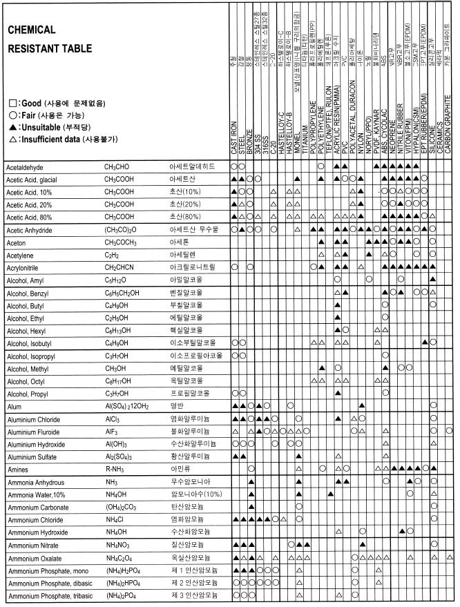
68 화학적부식표 72
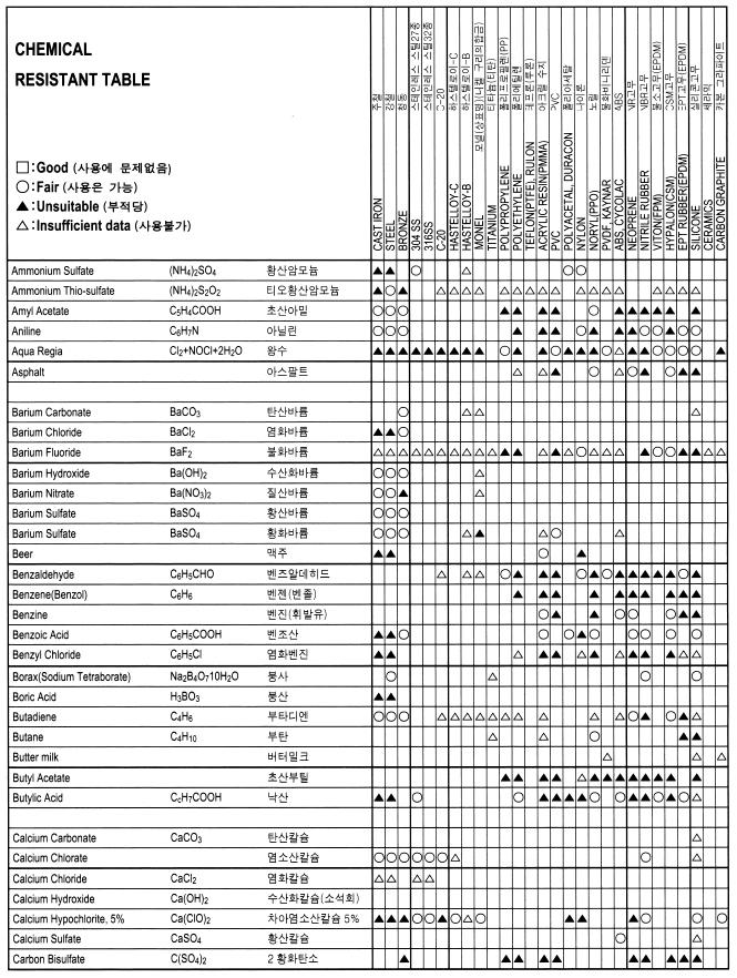
69 73
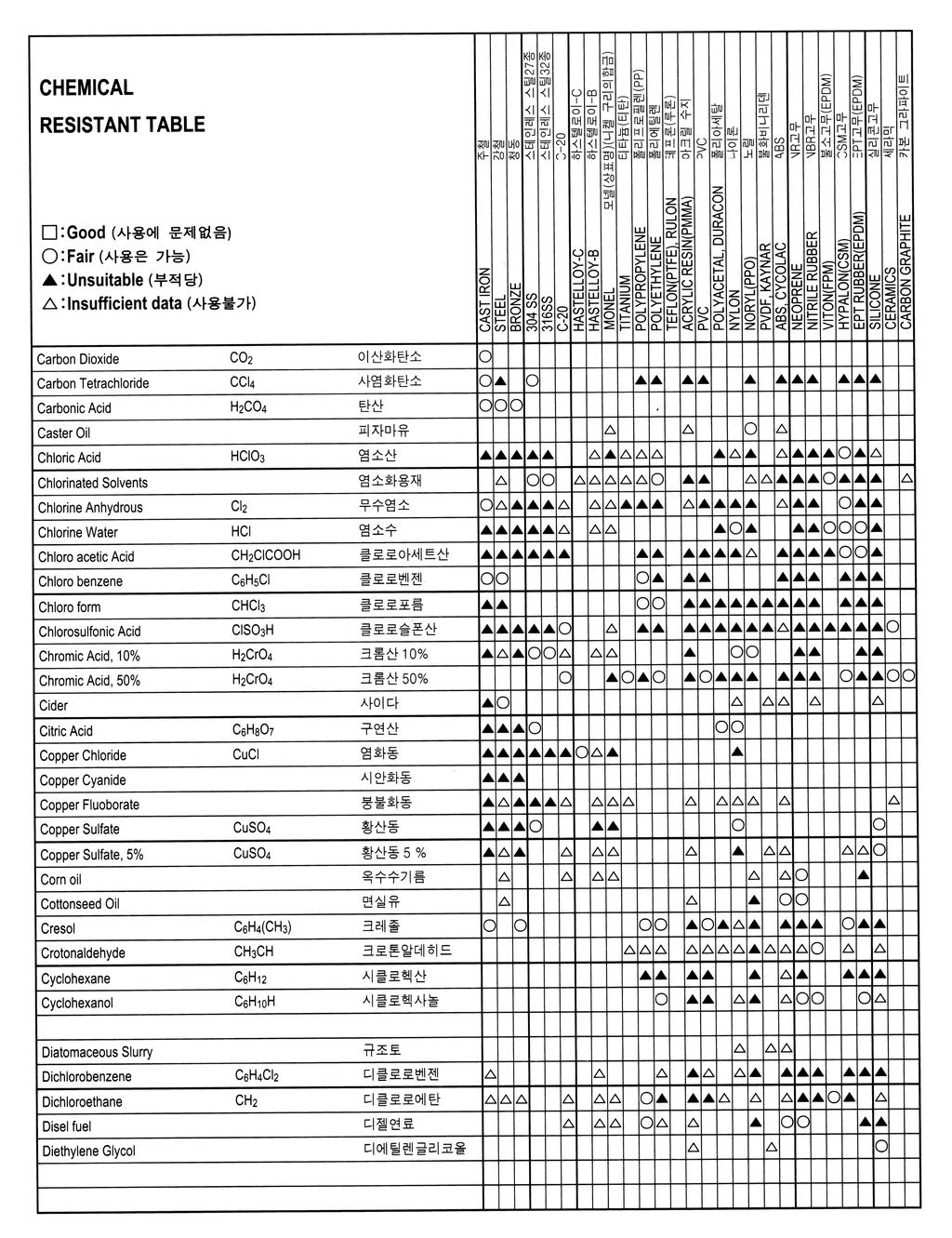
70 74
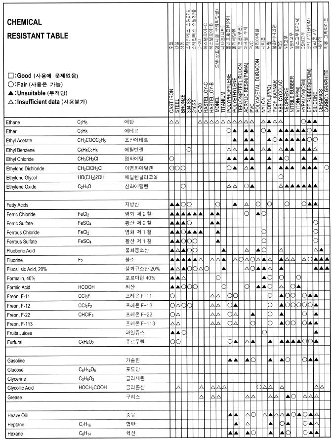
71 75
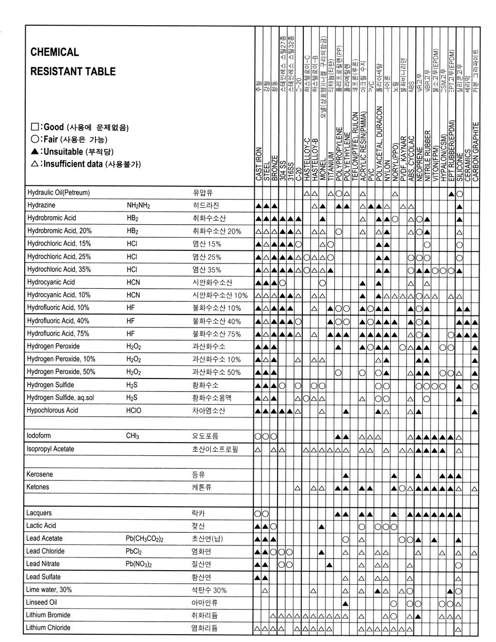
72 76
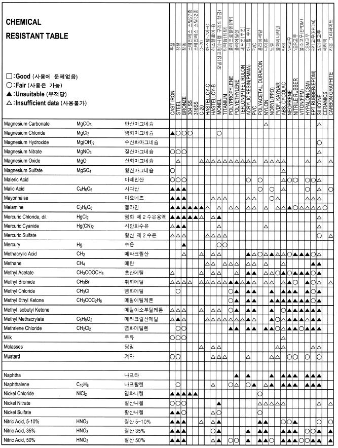
73 77
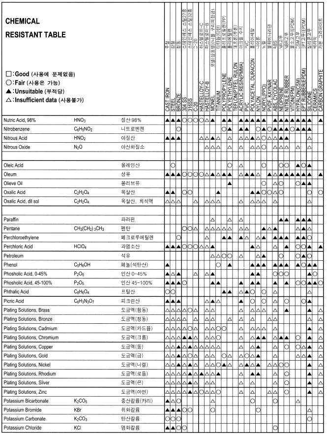
74 78
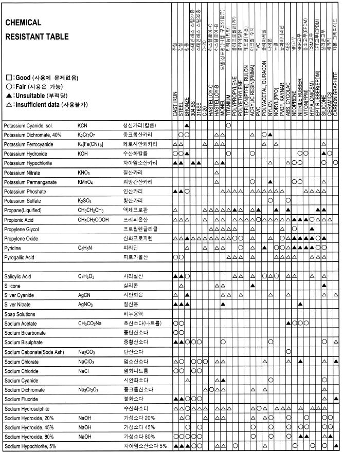
75 79
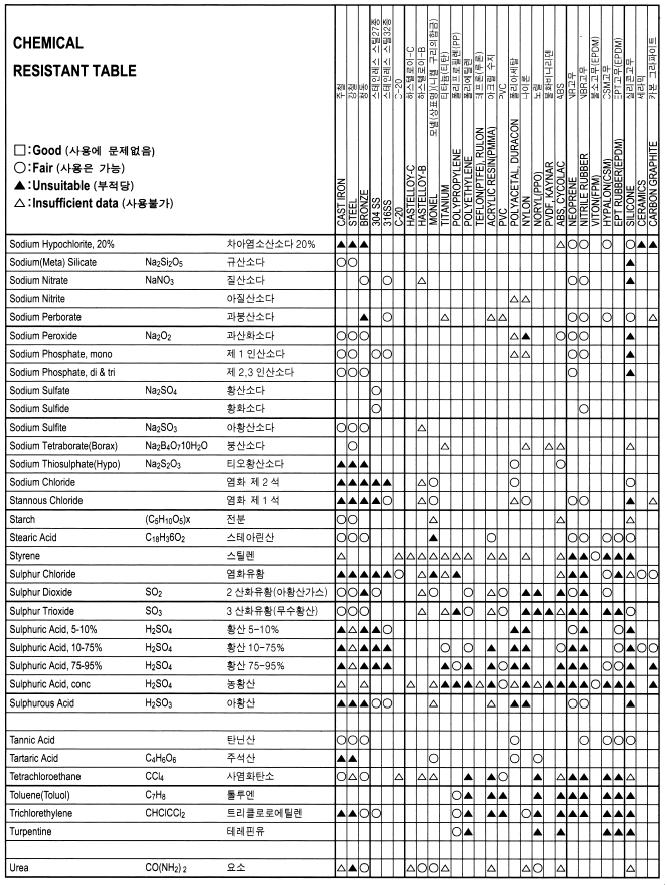
76 80
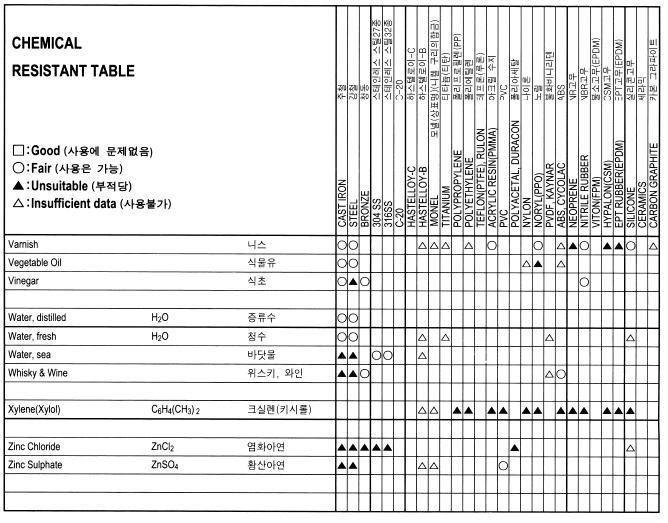
77 81
78 Dimensions normalisées des brides BRIDES ISO ou ANSI B16-5 DN PN class D C K L N f1 d / / / / / / /4 25/ / / / / / / / / / / / / BRIDES suivant DI501 DN PN D C K L N f1 d / / / / / / / / / / Notice technique A42.01 Sous réserve des modifications sans préavis Page4 82
79 CLASS 150#, 300# Flange Dimension ANSI 150# Nominal Size D t C g Bolt Bolt hole B A inch mm inch mm inch mm inch mm No. Dia. inch mm 1 / / / / / / 2 5 / / / 8 98 / / / 2 / / / / 2 / / / / / / 2 / / / / / 2 / / / / 8 / / / / / 8 / / / / 8 3 / / / / 4 / / / / 4 / / / 4 7 / / / / / 4 / / / / / / / / / / / / / / / / / / / / 4 32 Includes 1 / 16 raised face=1.6mm ANSI 300# Nominal Size D t C g Bolt Bolt hole B A inch mm inch mm inch mm inch mm No. Dia. inch mm / / 4 95 / / / / 2 / 8 16 / / / / / / 8 / / / / / 8 / / / / / / / 8 / / / / / / / 4 / / / / / / 8 / / / / / / 4 7 / / / / 4 / / / / / 4 / / / / / 4 7 / / / / / / 4 / / / / / / / / / / / / / / / / / / / / / / / / / / / / / / / / 8 35 Includes 1 / 16 raised face=1.6mm 83
80 CLASS 600#, 900# Flange Dimension ANSI 600# Nominal Size D t C g Bolt Bolt hole B A inch mm inch mm inch mm inch mm No. Dia. inch mm 1 / / / / / / 8 5 / / / / / / 4 / / / / 4 / / / / / / / 4 / / / / / / 4 / / / / 8 / / / / / / / 4 / / / / / 8 7 / / / / / / / / / / / / / / / / / / / / / / / / / / / / / / / / / / / / / / / / / / / / / / / 4 45 Includes 1 / 16 raised face=1.6mm ANSI 900# Nominal Size D t C g Bolt Bolt hole B A inch mm inch mm inch mm inch mm No. Dia. inch mm / / / / / / 4 / 8 22 / / / / / 4 / / / / / / / / / / / / / / / / / / / / / / / / / / / / / / / / / / / / / / / / / / / / / / / / / / / / / / / / / / / / / / / / / / / / / / / / / / / / 8 54 Includes 1 / 16 raised face=1.6mm 84
81 CLASS 150#, 300# Flange Dimension JIS 10K [mm] JIS 16K [mm] Nominal Size FLANGE Bolt Bolt Nominal Size FLANG Bolt Bolt D B A t f g c No. Hole Dia. D B A t f g c No. Hole Dia. / / / / / / / / / / / / / 2 (90) / 2 (90) (175) (225) JIS 20K [mm] JIS 30K [mm] Nominal Size FLANGE Bolt Bolt Nominal Size FLANG Bolt Bolt D B A t f g c No. Hole Dia. D B A t f g c No. Hole Dia. 3 / / / / / / / / / / / / / 2 (90) / 2 (90)
82 CLASS 600#, 900# Flange Dimension JIS 40K [mm] Nominal Size FLANGE Bolt Bolt B A D t f g c No. Hole Dia. 3 / / / / / / / 2 (90) JIS 63K [mm] Nominal Size FLANGE Bolt Bolt B A D t f g c No. Hole Dia. 3 / / / / / / / 2 (90)
83 MEMO Date : Note : 87
84 MEMO Date : Note : 88
85 MEMO Date : Note : 89
86 MEMO Date : Note : 90
416-2228 FAX : +82(31)416-2338 http://www.flowcountry.com http://www.flowcountry.co.kr http://www.ientek.com http://www. 질량유량계.com http://www. 아이엔텍.")
87 p Daeryung Technotown V # , Gasan-dong, Gumcheon-gu, Seoul, Korea TEL : +82(2) FAX : +82(2) p th Engineering B/D 1271, Sa 1-dong, Sangnok-gu, Ansan, Kyonggi-do, Korea TEL : +82(31) FAX : +82(31) 질량유량계.com 아이엔텍.kr master@flowcountry.com
Features. Description
 Features Fast response flow meter ideal for inert gas and liquid mass flow measurement applications Smart electronics permit field adjustment of critical flow meter settings Field validation of flow meter
780S Ultra High Purity Series
 Smart Ultra High Purity Thermal Gas Mass Flow Meter Features Measures mass flow directly, no seperate temperature or pressure inputs required Field adjustment of critical flow meter settings via on-board
Ultra High Purity Model 780S
 Smart Ultra High Purity Thermal Gas Mass Flow Meter Features Measures mass flow directly, no separate temperature or pressure inputs required Built-in flow conditioner which eliminates velocity-profile
C-1500 Series Velocity Transmitter for HVAC Application (Gas, Liquid) C Thermal Mass Flow Meters. Gas & Liquid Type Mass Flow meter
 C Thermal Mass Flow Meters. Gas & Liquid Type Mass Flow meter") Thermal Mass Flow Meters C-1500 Gas & Liquid Type Mass Flow meter Features - Fast Response flow meter ideal for inert gas and liquid mass flow measurement applications. - Smart electronics permit field
Thermal Mass Flow Meters C-1500 Gas & Liquid Type Mass Flow meter Features - Fast Response flow meter ideal for inert gas and liquid mass flow measurement applications. - Smart electronics permit field
Steel-Mass Model 640S
 Smart Insertion Thermal Gas Mass Flow Meter Features Direct mass flow monitoring eliminates need for seperate temperature and pressure inputs Accuracy +/- 1% of reading plus 0.5% of full scale Patented
7Flat-Trak Model 780S. Smart In-Line Thermal Gas Mass Flow Meter with Flow Conditioner. For information online...
 Smart In-Line Thermal Gas Mass Flow Meter with Flow onditioner Features Direct mass flow monitoring eliminates need for seperate temperature and pressure inputs Built-in flow conditioner which eliminates
Pro-V Multivariable Flowmeter
 Pro-V Multivariable Flowmeter Model M23 Insertion Meter M23-V flowmeter provides cost-effective volumetric flow monitoring solution for most liquids M23-VT incorporates temperature sensing to provide a
Pro-V Multivariable Flowmeter Model M22 In-line Vortex
 Pro-V Multivariable Flowmeter Model M22 In-line Vortex Pro-V TM Advantage: Volumetric or mass flow monitoring of most liquids, gases, and steam Multivariable meter delivers mass flow, temperature, pressure,
analytical bulk flow distance FLOW level pressure temperature industrial communication
 analytical bulk flow distance level pressure temperature industrial communication isolv THERMAL MASS METER Measuring Principle Self-heated Sensor Reference Sensor isolv Thermal Mass Flow Meters have two
For Multi-Parameter Meters see mvx
 Design Features VORTEX IN-LINE FLOW METERS For Multi-Parameter Meters see m Principles of Operation n No moving parts to wear or fail. n Electronics can be remotely mounted up to 30.5 m (0 ft). n No fluid
Steel-Mass Model 640S
 Immersible Thermal Gas Mass Flow Meter Direct mass flow monitoring eliminates need for separate temperature and pressure inputs Accuracy +/- 1% of reading plus 0.5% of full scale Patented Dry-Sense technology
For Multi-Parameter Meters see mvx
 VORTEX IN-LINE FLOW METERS Design Features For Multi-Parameter Meters see mvx Principles of Operation VX No moving parts to wear or fail. Electronics can be remotely mounted up to 30.5 m (0 ft). No fluid
PanaFlow MV82. Insertion Style Multivariable Flowmeter. GE Measurement & Control. Key Benefits. Applications
 GE Measurement & Control PanaFlow MV82 Insertion Style Multivariable Flowmeter Key Benefits Multivariable vortex flowmeter for measuring volumetric flow, temperature, pressure, density, and mass flow using
Flow and Energy Measurement F-5400 THERMAL MASS FLOW METER
 THERMAL MASS FLOW METER s Series Thermal Mass Flow Meters provide accurate and reliable flow measurement for natural gas, compressed air, and other industrial gas applications. Natural Gas Compressed Air
Design Features. General Description
 Model thermal Mass Flow Controllers are designed to indicate and control set flow rates of gases. The combines the characteristics and accuracy of conventional mass flow devices into a unique compact design
GFM. Typical Aluminum GFM Mass Flow Meter NIST MASS FLOW METERS. Principles of Operation. Design Features
 Design Features Rigid metallic construction. Maximum pressure of 1000 psig (70 bars). Leak integrity 1 x 10⁻⁷ of helium. NIST traceable certification. Built-in tiltable LCD readout. 0-5 Vdc and 4-20 ma
Technical Data Sheet High Performance Digital Gas Mass Flow Meters and Controllers Features Description
 Smart-Trak Model 100 High Performance Digital Gas Mass Flow Meters and Controllers Features Measure & control gas mass flow rates up to 1000 slpm True digital performance provides high accuracy and great
Max-Trak Model 180. Technical Data Sheet. NEMA 6 / IP67 Compliant Industrial Mass Flow Meters and Controllers For Gases
 NEMA 6 / IP67 Compliant Industrial Mass Flow Meters and Controllers For Gases Features Industry s only NEMA 6/IP67 industrial MFC affords wash down protection eliminating the need for secondary enclosures
Over 20,000 Strain Gage Target flowmeters installed since 1952.
 Over 20,000 Strain Gage Target flowmeters installed since 1952. Liquid, gases, superheated and saturated steam from -320 to 500 O F and up to 15,000 psi. No frictional moving parts. Designed to withstand
Flow metering in gases Introduction to COMBIMASS family
 Flow metering in gases Introduction to COMBIMASS family - physical principle, basic information - different types of instruments, pricing & delivery time Sales Training Germany October 17 th to 19 th,
3000 Series OPTIMASS Mass Flowmeter. Stainless Steel Hastelloy
 KROHNE 07/2005 7.02446.25.00 GR 3000 Series OPTIMASS Mass Flowmeter with single Z-shaped measuring tube Stainless Steel Hastelloy Status: 10/99 One tube no limits No limits with tube material No limits
KMT. Thermal Mass Flow Meter. for Compressed Air and Gases. Measuring range: m3n/h m3 N
 Thermal Mass Flow Meter for Compressed Air and Gases measuring monitoring analysing KMT Measuring range: 0.32... 63 m3n/h... 3.5... 1400 m3 N /h Accuracy: ±2,5% of reading + 0,15% of full scale p max :
TEK-THERMAL 1700B. Thermal Mass Flowmeter. FLOW. Technology Solutions
 Technology Solutions TEK-THERMAL 1700B Thermal Mass Flowmeter FLOW www.tek-trol.com Flow Level Temperature Pressure Valves Analyzers Accessories TekValSys Introduction Tek-Thermal 1700B Thermal Mass Flowmeters,
Brooks TMF-Zone 1 Models 5816-Ex/5864-Ex
 Data Sheet DS-TMF-586Ex-MFC-eng TMF-Zone Brooks TMF-Zone Models 586-Ex/5864-Ex Customer Benefits Assured process accuracy and repeatability Long-term reliability Reduced maintenance CE certified Improved
MASS FLOW SYSTEMS MASS FLOW MEASURING, CONTROLLING AND BLENDING SYSTEMS
 MASS FLOW SYSTEMS MASS FLOW MEASURING, CONTROLLING AND BLENDING SYSTEMS Using state-of-the-art measuring and microprocessor technologies, Advanced has assembled a series of systems which can measure mass
Technical Data Sheet. OPTIMASS 7000 Custody Transfer Mass Flowmeter
 Technical Data Sheet KROHNE 12/2004 7.02516.21.00 CH/GR OPTIMASS 7000 Custody Transfer Mass Flowmeter with single straight measuring tube OIML R117 Pattern Approval Accuracy classes 0.3 / 0.5 / 1.0 / 1.5
Thermatel Model TA2 Mass Flow Transmitter
 Thermatel Model TA2 Mass Flow Transmitter D E S C R I P T I O N Thermatel Model TA2 Thermal Mass Flow Transmitter provides reliable mass measurement for air and gas flow applications. The powerful, yet
Pro-V Multivariable Flowmeter Model M22 In-line Vortex
 Pro-V Multivariable Flowmeter Model M22 In-line Vortex Pro-V TM Advantage: Volumetric or mass flow monitoring of most liquids, Multivariable meter delivers mass flow, temperature, pressure, and density
COMPAFLOW. Compressed Air. Volumetric flow. Gas. Mass flow. Steam. Net volumetric flow. Liquid
 Volumetric flow Compressed Air Mass flow Gas Net volumetric flow Steam Liquid Universal compact orifice flow meter combines a compact orifice flow sensor and sotiphicated converter One-piece flow sensor,
TransPort PT878GC Panametrics Portable Gas Ultrasonic Flowmeter. GE Sensing. Applications. Features
 Applications The TransPort PT878GC clamp-on gas flowmeter is a complete ultrasonic flow metering system for measurement of most gases, including: Natural gas Compressed air Fuel gases Erosive gases Corrosive
Vortex flow sensor VA Di Ex-d with integrated, configurable transducer UVA in a flameproof enclosure for applications in explosive atmospheres
 Vortex flow sensor VA Di Ex-d with integrated, configurable transducer UVA in a flameproof enclosure for applications in explosive atmospheres Drawing 1 VA Di ZG1 Ex-d Measured variables actual flow rate
Two-Wire In Situ Oxygen Analyzer (550 to 1400 C)
") Product Data Sheet PDS 106-581.A01 March, 2004 Model 5081FG Two-Wire In Situ Oxygen Analyzer (550 to 1400 C) Intrinsically safe: - CENELEC EEx ia IIC - Class I Div. I Gr. B, C, D (pending) Operates at
Product Data Sheet PDS 106-581.A01 March, 2004 Model 5081FG Two-Wire In Situ Oxygen Analyzer (550 to 1400 C) Intrinsically safe: - CENELEC EEx ia IIC - Class I Div. I Gr. B, C, D (pending) Operates at
AFC. SDPROC and AFC Analog Mass Flow Controller ANALOG MASS FLOW CONTROLLERS. Principles of Operation. Design Features
 ANALOG MASS FLOW CONTROLLERS Model AF mass fl ow controllers are designed to indicate fl ow rates and control set fl ow rates of gases. Each of these units incorporates an advanced straight tube sensor
KMT. Thermal Mass Flowmeter. for compressed air and gases. Measuring range: Nm³/h Nm³/h
 Thermal Mass Flowmeter for compressed air and gases measuring monitoring analysing KMT Measuring range: 0.32... 63 Nm³/h - 263.4... 263350 Nm³/h Accuracy: ± 1.5% of reading + 0.5% of full scale ( DN 50)
TransPort PT878GC Panametrics Ultrasonic Portable Gas Flowmeter. GE Infrastructure Sensing. Features. Applications
 Applications The TransPort PT878GC clamp-on gas flowmeter is a complete ultrasonic flow metering system for measurement of most gases, including: Natural gas Compressed air Fuel gases Erosive gases Corrosive
XMO2. Panametrics Smart Oxygen Analyzer. Applications. Features. bhge.com. An oxygen transmitter for use in:
 XMO2 Panametrics Smart Oxygen Analyzer Applications An oxygen transmitter for use in: Inerting/blanketing liquid storage tanks Reactor feed gases Centrifuge gases Catalyst regeneration Solvent recovery
How to specify a product. Process Sensors and Mechanical Instruments
 How to specify a product Process Sensors and Mechanical Instruments Keep the overview. Here is some guideline information on how to specify our products. Intended as supplementary help to specification
C-Flow Coriolis Mass Flow Meters
 Coriolis Mass Flow Meters Ready for Take Off The New Compact C-Flow Küppers Elektromechanik GmbH The C-Flow The C-Flow Coriolis Mass Meters consist of two components: KCE Transmitter KCM Transducer 2 KEM
The M-Series Eletta Flow Meter High accuracy DP Flow Meter with multiple functions
 The M-Series Eletta Flow Meter High accuracy DP Flow Meter with multiple functions Flow Meter with multiple functions for gases and liquids M3 The M-series Flow Meter, with its versatile and user-friendly
Vortex Flow Sensor VA Di Ex-d for flow measurement in gases; with integrated, configurable transducer UVA in Ex-d housing
 Vortex Flow Sensor VA Di Ex-d Vortex Flow Sensor VA Di Ex-d for flow measurement in gases; with integrated, configurable transducer UVA in Ex-d housing Drawing 1 Measurable variables actual flow rate actual
Mass Flow Meter (MFM) for Gases
 for Gases") 873 Mass Flow Meter (MFM) for Gases Direct flow measurement by MEMS- Technology for nominal flow rates from 1 ml N /min to 8 l N /min (N 2 ) High accuracy Short response time Compact design and digital
873 Mass Flow Meter (MFM) for Gases Direct flow measurement by MEMS- Technology for nominal flow rates from 1 ml N /min to 8 l N /min (N 2 ) High accuracy Short response time Compact design and digital
Mass Flow Controller (MFC) for Gases
 for Gases") Mass Flow Controller (MFC) for Gases Type 8713 can be combined with... Direct flow measurement by MEMS- Technology for nominal flow rates from 1 ml N /min to 8 l N /min (N 2 ) High accuracy and repeatability
Mass Flow Controller (MFC) for Gases Type 8713 can be combined with... Direct flow measurement by MEMS- Technology for nominal flow rates from 1 ml N /min to 8 l N /min (N 2 ) High accuracy and repeatability
2 Overview. SITRANS P measuring instruments for pressure. Transmitters for gage and absolute pressure. Z series for gage pressure
 Z series for gage pressure Overview Design The main components of the pressure transmitter are: Brass housing with silicon measuring cell and electronics plate Process connection Electrical connection
DTG - LCD Digital Temperature Gauge USER MANUAL
 DTG - LCD USER MANUAL Page 1 of 7 USERS GUIDE page 1. Description 3 2. Function 3 3. Safety Instruction 3 3.1. Safety Conventions 3 3.2. Proper Use 3 4. Installation 4 4.1. Unpacking 4 4.2. Storage 4 4.3.
THERMAL MASS FLOW MEASUREMENT FOR GASES
 THERMAL MASS MEASUREMENT FOR GASES Make the Wise Choice. Choose Sage Flow Meters. A Commitment to Higher Performance SAGE METERING is a manufacturer of high performance Thermal Mass Flow Meters which measure
Integral type Differential pressure flowmeter VNT Series
 Integral type Differential pressure flowmeter VNT Series OUTLINE VH series Wafer-Cone differential pressure flowmeter and high precision differential pressure transmitter are integrated into one flowmeter.
7000 Series OPTIMASS Mass Flowmeters. Titanium Hastelloy Stainless Steel
 KROHNE 04/2003 7.02445.71.00 GR 7000 Series OPTIMASS Mass Flowmeters with single straight measuring tube Titanium Hastelloy Stainless Steel One tube no limits No limits with tube material No limits with
Expert Hydrostatic Level Transmitters
 Expert Hydrostatic s General Features MJK Expert hydrostatic level transmitters are designed for level measurement by submerging the transmitter in open channels, drains and tanks. Expert hydrostatic level
RCD - Ultra-Rugged Differential Pressure Flowmeter
 0.15-1 to 85-600 GPM Liquids 2.5-25 to 300-1700 SCFM Gases 1/2 to 3 Line Sizes Bronze or 316-Ti Stainless Steel Mechanical Indicator, Digital Indicator, Transmitters and Switches Available Custom Calibrations
Excellent Vortex Flowmeter INSERTION Type BATTERY POWERED EX DELTA
 Excellent Vortex meter INSERTION Type BATTERY POWERED EX DELTA GENERAL SPECIFICATION GS.No.GBD604E-6 GENERAL The battery-powered EX DELTA is a dedicated on site monitor with a wide variety of applications
SITRANS P measuring instruments for pressure
 SITRANS P measuring instruments for pressure Z series for gage pressure Siemens AG 008 Overview Design The main components of the pressure transmitter are: Brass housing with silicon measuring cell and
Torque Tube TB300 Digital Transmitters
 Page 1 of 7 7E.300-E Issue 4-2009 Description Series TB300 torque tube liquid level instruments utilize the buoyancy exerted on a displacer when immersed in a liquid. The buoyancy on the displacer is proportional
deltaflowc deltaflowc Venturi or Probe
 deltaflowc Mass Flowmeter for Gases - Multivariable with ultra fast dp, p and T-sensors - Compact, accurate and user-friendly - Ideal for OEMs deltaflowc Venturi or Probe Precise mass flow metering deltaflowc
Thermal Energy Flowmeter Model KEC. Application Range. Special Features
 Thermal Energy Flowmeter for gases measuring monitoring analysing KEC O O Direct mass flow rate measurement of gases OMeasuring O accuracy: ± 0.3% of full scale ±1.5% of reading on request: ± 0.3% of full
SideTrak 830/840. Process Gas Mass Flow Meters and Controllers. FEATURES DESCRIPTION
 Process Gas Mass Flow Meters and Controllers FETURES n Direct monitoring of mass flow eliminates need for ancillary pressure and temperature sensing n Patented straight sensor tube with access ports permits
Differential Pressure Transmiter
 Differential Pressure Transmiter Description The is an economical alternative to established differential pressure transmitters. It combines state of the art electronics and a high performance sensor;
Level transmitter LT 100
 KROHNE 09/2001 7.02363.21.00 GR/PRINTO Level transmitter LT 100 Status: 10/99 Variable area flowmeters Vortex flowmeters Flow controllers Electromagnetic flowmeters Ultrasonic flowmeters Mass flowmeters
Autocalibration Systems For In Situ Oxygen Analyzers
 Product Data Sheet PDS 106-340AC SPS 4000, IMPS 4000, and MPS 3000 January, 1999 Autocalibration Systems For In Situ Oxygen Analyzers Cost-effective autocalibration systems for installations ranging from
2600T Series Pressure Transmitter Models 264DC Differential and 264HC Gage Level Transmitters. Kent-Taylor
 INDUSTRIAL INSTRUMENTS AND CONTROLS SPECIALIST Kent-Taylor 2600T Series Pressure Transmitter Models 264DC Differential and 264HC Gage Level Transmitters Features Include Base accuracy : ±0.075% Span limits
Type N-10, N-11 Hazardous Area Non-incendive Transmitters
 Electronic Pressure Catalog > Hazardous Area > N-10, N-11 Type N-10, N-11 Hazardous Area Non-incendive Transmitters Applications Natural gas compressors Wellhead monitoring Pipeline pressure General industrial
Energy Management solutions for compressed air and industrial gases. vpinstruments.com
 Energy Management solutions for compressed air and industrial gases vpinstruments.com 6 Introduction VPINSTRUMENTS Measure, Discover and Save! Compressed air is a very expensive energy source. In fact,
TFE-LINED VAREA-METER PVC-TUBE VAREA-METER
 TFE-Lined Varea-Meter PVC-Tube Varea-Meter USFilter s Wallace & Tiernan Products offers a choice of two straight-through rotameters for metering difficult fluids and gases. The TFE-lined Varea-Meter is
Vortex Flow Meter Wafer or Flange Connection. - Steam - Liquid - Gas
 Vortex Flow Meter Wafer or Flange Connection - Steam - Liquid - Gas Working Principle & Circuit Diagram Working Principle When a column body placed in flowing fluids in pipe, a series of vortices will
T EK-COR 1100A. Coriolis Mass Flowmeter. FLOW. Technology Solutions
 Technology Solutions T EK-COR 1100A Coriolis Mass Flowmeter FLOW www.tek-trol.com Flow Level Temperature Pressure Valves Analyzers Accessories TekValSys Introduction There can often be more than one type
better measurement Simply a question of SCHMIDT Flow Sensor SS The cost-effective alternative in pressurised systems up to 10 bars.
 Simply a question of better measurement SCHMIDT Flow Sensor SS 20.261 The cost-effective alternative in pressurised systems up to 10 bars. Compressed air technology Industrial processes A cost analysis
SmartTrak 100HP. Ultra-High Pressure Digital Gas Mass Flow Meters & Controllers. FEATURES DESCRIPTION
 Ultra-High Pressure Digital Gas Mass Flow Meters & Controllers FEATURES n Ideal for pilot plants, hydrogenation reactors, and autoclave processes n Measure and control gas mass flow rates over an inlet
DM01. Please visit our website: Battery Powered Precision Digital Gauge. Stainless Steel Sensor. class 0.05
 DM0 Battery Powered Stainless Steel Sensor class 0.05 Nominal pressure from 0 00 mbar up to 0... 00 bar Special characteristics modular sensor concept data logger graphic display stainless steel housing
VersaFlow Vortex 100 Vortex Flow Meter Technical Datasheet. Specification. The all-in-one solution. Highlights. Industries.
 VersaFlow Vortex 100 Vortex Flow Meter Technical Datasheet 34-VF-03-05 September 3rd, 2008 Specification The all-in-one solution The VERSAFLOW is the only vortex flowmeter with integrated pressure and
X-Flow Mass Flow Controller 授权代理 : 北京品超思瑞科技学院公司
 X-Flow Mass Flow Controller 2 Highlights Parker Hannifin Precision Fluidics Division is excited to introduce X-Flow, a new easy to use general purpose mass flow controller for your instrument, lab, or
TH-1800-T TRX-700-CNG Converter
 TH-1800-T TRX-700-CNG Converter low detector The CNG fuel gas flowmeter is so accurate as to meet a demand of measuring the CNG directly by making the most use of our well-established mini-thermal flowmeter
9700 Transmitter Submersible hydrostatic level transmitter
 Specification sheet IP0078 October 2007 Level 9700 Transmitter Submersible hydrostatic level transmitter Description The 9700 series hydrostatic level transmitter is designed to perform in the most arduous
P9000 DESCRIPTION. For parts requiring RoHS compliance, please contact factory. P February /6
 P9000 High accuracy through digital compensation High thermal stability Rugged stainless steel construction Ideal for test stands High burst pressure limit DESCRIPTION The P9000 Series is a range of advanced,
Mass Flowmeters. Mass Flowmeters for Gases
 Mass Flowmeters Mass Flowmeters for Gases Fast, Accurate, Low Pressure Drop for critical measurement applications! Flow (Std l/min) Response to a step change in flowrate 300 200 100 4 Milliseconds 63%
Mass Flow Meter (MFM) for gases
 for gases") Mass Flow Meter (MFM) for gases Type can be combined with Inline MFM for nominal flow rates from 25 l N /min to 1,500 l N /min; 1/4 to 3/4 High accuracy Fast settling time Fieldbus option Special version
Mass Flow Meter (MFM) for gases Type can be combined with Inline MFM for nominal flow rates from 25 l N /min to 1,500 l N /min; 1/4 to 3/4 High accuracy Fast settling time Fieldbus option Special version
Installation, operating and maintenance Instructions for Seemag bypass level indicator
 Issue: S Date: 05-09-14 Type G35 General information The Seetru bypass magnetic level indicator, abbreviate SEEMAG, serves to show the filling level of fluids in tanks, basins, tubes etc. The Seemag operates
T EK-COR 1100A Coriolis Mass Flowmeter
 T EK-COR 1100A Coriolis Mass Flowmeter Instruction Manual Document Number: IM-1100A NOTICE Read this manual before working with the product. For personal and system safety, and for optimum product performance,
Analogue and Digital Mass Flow Meters and Controllers for Gases MASS-STREAM
 Analogue and Digital Mass Flow Meters and Controllers for Gases MASS-STREAM M+W Instruments Your partner Key Facts M+W Instruments was founded in 1988 and has always specialised in thermal mass flow meters
IDL01. Battery Powered Precision Digital Gauge for Leak Testing. Stainless Steel Sensor. class 0.05
 IDL0 Battery Powered Precision Digital Gauge for Leak Testing Stainless Steel Sensor class 0.05 Nominal pressure from 0 00 mbar up to 0... 00 bar Special characteristics modular sensor concept data logger
Features. Main Voltage: Vdc. Input Control Signal: 0-5 Vdc or 4-20 madc (Sourcing) Monitor Output Voltage: 0-5 Vdc or 4-20 madc (Sourcing)
 Monitor Output Voltage: 0-5 Vdc or 4-20 madc (Sourcing)") 1 X-Flow Mass Flow Controller Flow Range from 0.8 ml/min to 20 l/min Target Markets Laboratory and Process Instrumentation Pharma / Bio-Pharma Equipment Air Quality Monitoring Systems Furnace and Coatings
1 X-Flow Mass Flow Controller Flow Range from 0.8 ml/min to 20 l/min Target Markets Laboratory and Process Instrumentation Pharma / Bio-Pharma Equipment Air Quality Monitoring Systems Furnace and Coatings
DM01. Battery Powered Precision Digital Gauge. Stainless Steel Sensor. class 0.05
 Battery Powered Stainless Steel Sensor class 0.05 Nominal pressure from 0 00 mbar up to 0... 00 bar Special characteristics modular sensor concept data logger graphic display stainless steel housing Ø
Online data sheet FLOWSIC30 GAS FLOW METERS
 Online data sheet A B C D E F H I J K L M N O P Q R S T Ordering information LTRASONIC GAS FLOW METER FOR CTION Type Part no. On request The exact device specifications and performance data of the product
ETd 04. Battery Powered Precision Digital Gauge. Stainless Steel Sensor. Type: ETd 04. class 0.05
 Battery Powered Stainless Steel Sensor class 0.05 Nominal pressure from 0 100 mbar up to 0... 400 bar Special characteristics modular sensor concept data logger graphic display stainless steel housing
Variable Area Flow Meters
 Variable Area Flow Meters Over sixty years of variable area meter expertise Brooks started designing and manufacturing variable area (VA) meters, also referred to as rotameters, in 1946. Now, with more
UNDERSTANDING, ACCELERATED
 UNDERSTANDING, ACCELERATED MEASURE FLOW, PRESSURE, AND TEMPERATURE ALL IN ONE INSTRUMENT! Designed for Performance TSI thermal mass flowmeters incorporate a proprietary platinum film sensor design for
Equipment. Flowmeter Tutorial
 Flowmeter Tutorial Flowmeters are used to measure the rate of flow of liquids or gases. They do not control the rate of flow unless they are equipped with a control valve or flow controller. There are
Porter Analytical & Industrial Products
 Porter Analytical & Industrial Products Porter Analytical & Industrial Products Engineered to Excel in Critical Applications The Porter Instrument Division of Parker Hannifin Corporation is a leading manufacturer
Ultrasonic level transmitter and indicator
 Ultrasonic level transmitter and indicator No contact with the product Compact design with polycarbonate housing (electronics and display). Remote display available on request Very good resistance in corrosive
better measurement Simply a question of
 Simply a question of better measurement SCHMIDT Flow Sensor SS 20.600 The powerful industrial professional for demanding applications involving air and gases. Industrial processes Pneumatic technology
GP1 & GP2. Electropneumatic Regulators FOR PRESSURE CONTROL TO 1,000 PSI
 GP1 & GP2 Electropneumatic Regulators FOR PRESSURE CONTROL TO 1, PSI GP1 & GP2 Functional Description The GP series control valve is an electronic pressure regulator designed to precisely control the pressure
Two-Wire In Situ Oxygen Analyzer (550 to 1400 C)
") Product Data Sheet PDS 106-581.A01 September, 2007 Model 5081FG Two-Wire In Situ Oxygen Analyzer (550 to 1400 C) Intrinsically safe: ATEX, Zone 1, EEx ia IIC T4 Class I, Div. I, Gr. A, B, C, D T4 Operates
Product Data Sheet PDS 106-581.A01 September, 2007 Model 5081FG Two-Wire In Situ Oxygen Analyzer (550 to 1400 C) Intrinsically safe: ATEX, Zone 1, EEx ia IIC T4 Class I, Div. I, Gr. A, B, C, D T4 Operates
Turbine Flowmeters for Gas Applications
 Turbine Flowmeters for Gas Applications Description Flow Technology s FT Series turbine flowmeters utilize a proven flow measurement technology to provide exceptionally reliable digital outputs. Because
High Performance Digital Gas Mass Flow Meters & Controllers
 High Performance Digital Gas Mass Flow Meters & Controllers FEATURES n Measure and control gas mass flow rates up to 1000 slpm n Pressure up to 500 psig (34.5 barg). For pressures greater than 500 psig
Mass Flow Controller (MFC) for Gases
 for Gases") Mass Flow Controller (MFC) for Gases Bypass MFC with capillary technology for nominal flow rates from 5 ml N /min to 15 l N /min Applicable for aggressive gases Compact design and digital communication
Mass Flow Controller (MFC) for Gases Bypass MFC with capillary technology for nominal flow rates from 5 ml N /min to 15 l N /min Applicable for aggressive gases Compact design and digital communication
VIC offers a variety of Calibrated Gas Leaks
 CALIBRATED GAS LEAKS VIC offers a high quality line of calibrated gas leaks traceable to National Institute of Standards Technology (NIST). Calibrated gas leaks are used to provide a controlled delivery
THE INSIDE STORY OF THE F-SERIES:
 BRFSERIES15E THE INSIDE STORY OF THE FSERIES: Response Time < 1ms Analog Differential ressure Sensor for Real Time Measurement Analog Output = Measured Flow Many Connector Options I65 Housing ressure Compensated
Flow Sensors & Hydrometers Specification Sheet
 Baseline Flow s and Hydrometers Baseline s smart flow sensors and hydrometers are two-wire ready flow measurement and control devices that are pre-programmed with the correct K and Offset values. In addition,
Electro-Pneumatic Converter YT-940 SERIES
 Electro-Pneumatic Converter YT-940 SERIES PRODUCT MANUAL VERSION 1.00 Contents 1. Introduction 3 1.1 General information for the users. 3 1.2 Manufacturer Warranty 3 1.3 Explosion Proof Warning. 4 2. Product
RTX 1000H Series. Versatile Transmitters for a World of Pressure. GE Measurement & Control. Features
 GE Measurement & Control RTX 1000H Series Versatile Transmitters for a World of Pressure GE Measurement & Control is renowned for the design and manufacture of compact and rugged high performance pressure
ALL-IN-ONE MINI THERMAL MASS FLOWMETER
 INDICATION, TOTAIZATION, -POINT AARM, DC to ma AND PUSE OUTPUT BY ONE UNIT TF-T Series A-IN-ONE MINI TERMA MASS FOWMETER OUTINE TF-T MINI TERMA MASS FOWMETER is for the measurement of mass flow rate of
TEK-SUB 4800B. Submersible Level Transmitter. Flow Level Temperature Pressure Valves Analyzers Accessories TekValSys LEVEL
 Technology Solutions TEK-SUB 4800B Submersible Level Transmitter LEVEL Flow Level Temperature Pressure Valves Analyzers Accessories TekValSys Introduction The Tek-Sub 4800B Submersible Level Transmitter