W I L D W E L L C O N T R O L SNUBBING OPERATIONS
|
|
|
- Rudolf Quinn
- 5 years ago
- Views:
Transcription


1 SNUBBING OPERATIONS
2 Snubbing Operations Learning Objectives You will learn - Various activities suitable for snubbing operations. Best practices and techniques for conducting snubbing operations. The types of snubbing units, components, tools and BOPs. How to handle common problems confronting snubbing operators, and how to handle equations relating to snubbing operations. Minimal safety and control procedures regarding snubbing operations.
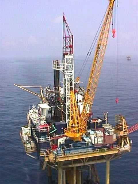
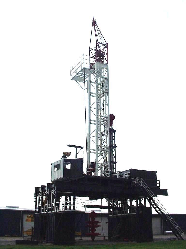
3 Snubbing Operations Overview (Hydraulic) Snubbing units are designed to run pipe into and out of a well under pressure. Snubbing units can rig up/down in a fraction of the time of a conventional rig or workover unit. Snubbing units can perform most operations normally performed by conventional rigs and workover units. Certain safety issues must be addressed because of the small pipe size used. Units can be used for drilling, or for workovers on live wells.
4 Snubbing Operations Overview Snubbing Operations can be broken down into two major categories - Live Well Operations Dead Well Operations
5 Snubbing Operations Overview In Live Well Operations there are usually production issues that require the well to be worked under pressure or there are mechanical problems that prevent the well from being killed. Dead Well Operations are usually done for issues related to rig costs or space and mobilization issues.
6 Snubbing Operations Overview Live Well Operations Well Control Recovery Formation Protection Workovers with Mechanical Problems Dead well Operations Workovers Tubing Changeouts Fishing Coil & Wireline Tools also under Pressure Stimulation Procedures
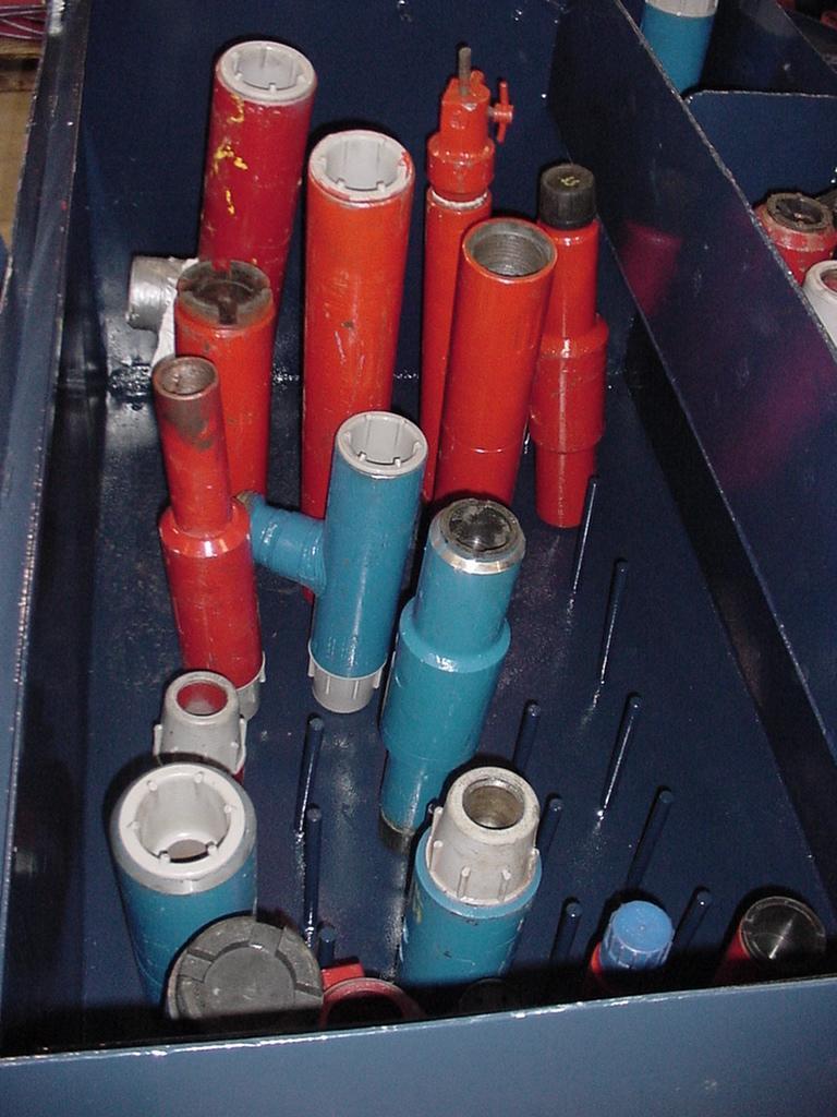
7 Snubbing Applications Snubbing - pipe raising / lowering operations where specialized equipment is used to overcome forces trying to push the pipe out of the hole due to shut-in wellbore pressures. Running/pulling production strings Resetting weight on packers Fishing operations Squeezing cement slurry Washing perforations, sand Well control Milling / drilling

8 Hydraulic Unit Control Panel Traveling Slips Counterbalance Winch Telescoping Mast Hydraulic Cylinders Telescoping Guide Tube Stationary Slips Access Window Equalizing Loop Ram Preventers Guide Tube Tubing Stripper or Annular Preventer Vent Line BOP Stack Choke Line
9 Hydraulic Unit - Components Work Basket & Controls Platform for operators and helpers Operator console controls - Jacking direction controls Weight indicators & pressure gauges Rotary direction & torque controls Slips and stripping BOP bank valves Pump Controls & gauges Counterbalance console for pipe handling Tongs and controls

10 Hydraulic Unit - Components

11 Work Basket
12 Work Basket Jack Cylinders Provide lifting and lowering force. Lifting forces from 120k to 600k. Slip Assemblies Traveling slips attached to operating cylinders, move with Jack head. Stationary slips hold tubing for connections and while additional strokes are taken. Lower stationary slips used when pipe is heavy. Inverted stationary slips used when pipe is light.

13 Jack Cylinders

14 Slip Assembly
15 Slip Assembly Telescoping Mast- Gin Pole (not shown) Lifts and lowers tubing and tools on and off platform Tong Pole Mast Holds tong and hydraulically moves tong into working position. BOP Snubbing Loop Used to equalize and bleed stripper ram cavities when snubbing from ram to ram.
16 BOP Snubbing Loop
17 Rig-Assist Unit Components The RA snubbing unit uses a rig s block thru a pulley system for snubbing force. As block moves up the pipe moves in the hole; as the block moves down the pipe moves up confusing at first but effective. Unit capacity limited by pulley cable load limit and well pressure against tubulars. Traveling Slips Stationary Slips Unsupported length if no guide tube used
18 Rig-Assist Unit Components Once a balance point is reached, the snubbing unit is not needed and rig can then strip string to bottom. Exercise care due to unsupported pipe lengths. The RA unit has no guide tube so buckling is a concern. The RA unit can be rigged up quickly and is less costly than hydraulic units.
19 Rig-Assist Unit Components Applications Snubbing drill pipe back to bottom for well killing or UG blowouts. Running/pulling tubing, casing, or a workstring under pressure. Running / Installing / Resetting packers. Pulling tubing with a hole that prevents conventional kills. Drilling / Fishing / Milling under pressure. Acidizing and/or washing. Squeeze jobs and plug-backs.
20 Rig-Assist Unit Components Typical Snubbing Sequence Close Lower Ram, bleed Cavity Pressure, open Upper Ram & Lower Tubing. Close Upper Ram, Pressure Cavity, open Lower Ram and continue. Snub until Tool Joint blocked by Closed Ram.

21 Rig-Assist Unit Components

22 Rig-Assist Unit Components Travelling Assembly Travelling Slip Assembly Leaf Chain Hydraulic Cylinder Assembly Drillpipe Sheave Assembly Stationary Slip Assembly
23 Barrier A Barrier is any device or substance that prevents the flow of the well bore fluids. Primary Barrier Used during normal operations, e.g., a stripper rubber, BPV and stripping rams. A liquid (e.g., brine) used as a barrier must be able to control pressures. - Must be able to monitor density. - Must be able to adjust density.
24 Barrier Secondary Barrier Used in support of normal operations or as a contingency, e.g., a BOP, stripping rams and back pressure valve Tertiary Barrier Used in emergency, e.g., a shear seal, a master valve that cuts wireline, safety head
25 Barrier Closeable Barriers Ability to open and close, e.g., BOP, safety valves Fluid Barriers Seawater, brines, drilling fluid Mechanical Barriers Closes off the flow path by sealing against casing or tubing wall - positive plug in tubing-n nipple Combination Barriers A combination of mechanical and fluid barriers may be used Testing of a Barriers Test in direction of Flow. (BPV against flow) Test to maximum anticipated surface pressure
26 BOPs and Accessories Stripper Inside BOP - Stops flow up snubbing string. Annular BOP - Used at low pressure depending on well conditions. Stripper Rams - Used if well pressure exceeds annular rating - minimum of two stripper rams required to pass tool joints. Pump/Bleed Manifold Upper Stripper Ram Lower Stripper Ram Upper Safety Ram Blind Ram Kill Line Shear Ram To Choke Safety Ram Crown Valve
27 BOPs and Accessories Stripper rams must be separated by a spool for lubricating tool joints and have pump in and bleed off capability between strippers. Safety Rams - Actually pipe rams - allow safe replacement of stripper ram packing - two rams for well pressure > 5,000 psi. Shear or Blind Rams - Cut pipe or seal wellbore - two rams for well pressure > 5,000 psi. Wellhead - Should have a minimum of two master valves, two blind rams or a combination of both below the BOP stack.

28 BOPs and Accessories Tubing Stripper Sometimes Called an Annular Capabilities and limitations Provides seal around Workstring under low Pressure situations Max. WP of 3000 psi Accepts variety pipe sizes This stripper relies on wellbore pressure for seal around pipe. Others use hydraulic pressure acting on a piston and packing element to maintain a seal.
29 BOPs and Accessories Hydraulic pressure applied through closing chamber to effect a seal. Opening by relieving pressure from closing chamber. Stripper is well bore assisted. Could be well pressure energized and may require reducing closing pressure with increasing surface pressure. Apply just enough closing pressure to gain a seal. Excessive closing pressure will shorten the life of the packing element.


30 BOPs and Accessories Hydril GK 7-1/16 3,000 and 5,000 psi WP Model similar to drilling GK in function and design; sized for workovers. Hydraulic pressure applied through closing chamber to underside of piston. Piston rises and causes constriction of packing element. Hydraulic pressure applied via opening chamber, piston t travels downward for element to open. Wear Plate Head Packing Unit Opening Chamber Piston Closing Chamber Sleeve


31 BOPs and Accessories Hydril GS 4-1/16 10,000 & 15,000 psi WP GS Snubbing Annular has all features of its drilling counterparts including well bore assistance. Piston Indicator Port Wear Plate Latch Head Release Ring Groove Opening Chamber Cover Install compensator bottle on closing line for tooljoints to pass through packing element. Packing Element Opening Chamber Operating Chambers Closing Chamber Piston Piston Seal Preventer Body


32 BOPs and Accessories Cameron 4-1/16 Snubbing Annular Preventer And Tubing Stripper 10,000 psi & 15,000 psi WP


33 BOPs and Accessories Cameron 4-1/16 S/QRC Snubbing Rams 15M psi WP


34 BOPs and Accessories Cameron 4-1/16 S/QRC 25M psi WP 7-1/16 S/QRC 20M psi WP


35 BOPs and Accessories Cameron Type UL 7-1/16 Ram Preventer 5M, 10M, and 15M psi WP


36 BOPs and Accessories The Cameron Type UM is specifically designed for workover and well servicing operations. Cameron 7-1/16 Type UM Ram Preventer 3,000 psi 15,000 psi WP


37 BOPs and Accessories Cameron Type U Preventer was designed for drilling applications, smaller sizes are used in workover and snubbing operations. Cameron 7-1/16 Type U Ram Preventer 3,000 psi 15,000 psi WP

38 BOPs and Accessories Bowen Double Snubbing Rams capable of either conventional workover or snubbing service.

39 BOPs and Accessories Stem Lock End Plate Rear Body Stem Pressure Plate Bolt Piston Bonnets Handle QD Coupling Preventer Body Sentry by Hydril 7-1/ psi to 5,000 psi WP Capable of either conventional workover or snubbing service.

40 BOPs and Accessories Safety Head Shear Samples
41 BOPs and Accessories Shear Tests Include Slick Line w/o Tension, 1 strand Slick Line w/o Tension, 10 strands Cable w/o Tension, 1 strand Core Cables w/o Tension, 10 strands 1.25", Wall Coiled Tubing l0 strands 3 Parallel Strings of Heavy Wall 1.5, 1.75, & 2.0 CT w/ 7/16 Cable inside
42 BOPs and Accessories Shear Tests Include 2 Parallel Strings of Heavy Wall 2.38 & 2.88 CT w/ 7/16 Cable inside 2" Sinker Bar, ANS 4230 Steel 3.5 Drill Pipe S-135, N/m (15.5 lbs/ft) 4 Tubing 13 Chrome L N/m (12.6 lbs/ft) tubing 4-5/8 Gravel Pack Screen w/ 2-3/8 Wash Pipe inside
43 Snubbing BOP Stacks Stack configurations vary greatly and the component selection is based on Maximum anticipated surface pressure Tapered or non-tapered workstring Hydrogen sulfide (H2S) resistant A non-tapered workstring Stack provides primary pressure control Configurations are examples only

44 Snubbing BOP Stacks 0-3,000 psi Stack
45 Snubbing BOP Stacks Notes for Testing ALL BOP Stacks Use an environmentally friendly test fluid. Test at low pressures ( psi). Test at rated working pressure of the stack. If rigged up on a drilling stack, the blind rams of the drilling stack may not hold working pressure from above. This may limit the test pressures of the snubbing stack.
46 Snubbing BOP Stacks Testing < 3,000 psi Stack Configuration STEP 1: Pick up a muleshoe and a length of workstring to cover the BOP stack; tag top master valve and lift string one foot above master valve; install a full opening workstring valve (TIW), in the open position and install a pump-in line. STEP 2: Open all valves on the stack, chokes, and equalizing loop. STEP 3: Close the stationary slips and use the travelling slips to pull tension on the workstring to ensure the workstring is not pumped out of the stack during the test procedures.
47 Snubbing BOP Stacks STEP 4 STEP 5 STEP 6 Close the lowest safety ram and perform the pressure tests (high and low); bleed the pressure and open the ram; repeat this procedure for the stripper ram. Fill with fluid before closing rams. Test each valve individually; first in the open position and then in the closed position. Test all inside valves to shorten tests. Function test each ram under rated working pressure.
48 Snubbing BOP Stacks 3,000 5,000 psi Stacks Non-tapered workstring. Stripper provides primary pressure control. Remove bleeder valve if ram-to-ram snubbing or stripping is to be done.
49 Snubbing BOP Stacks Stripper Bleed Valve Choke/valve Equalizing Loop Upper Stripper Ram Spacer Spool Bleed Valves Choke/valve Lower Stripper Ram Upper Safety Ram Lower Safety Ram Wellhead/ BOP Connection Bleed Valves Outlet Spool Outlet Spool
50 Snubbing BOP Stacks Testing 3,000 5,000 psi Stack STEP 1 Pick up a muleshoe and a length of workstring to cover BOP stack; tag top master valve and lift string one foot above master valve; install a full opening workstring valve (TIW) in the open position and install a pump-in line. STEP 2 Open all valves on the stack, chokes, and equalizing loop.
51 Snubbing BOP Stacks STEP 3 STEP 4 STEP 5 STEP 6 Close the stationary slips and use the travelling slips to pull tension on the workstring to ensure the workstring is not pumped out of the stack during the test procedures. Close the lower safety ram and test. Bleed pressure and open the ram. Close the upper safety ram and test. Bleed pressure and open the ram. Close the lower stripper ram and test. Bleed pressure.
52 Snubbing BOP Stacks STEP 7 STEP 8 STEP 9 STEP 10 With the lower stripper ram closed, individually test the valves below the stripper rams. Bleed pressure and open the lower stripper rams. Close upper stripper rams and test. Following test, bleed pressure but leave the rams closed. With upper stripper rams closed, test each valve individually bleeding pressure after each test. Function test each ram at full rated working pressure.
53 Snubbing BOP Stacks Surface Pressure: 5,000 10,000 psi Use for non-tapered string. Use an environmentally friendly test fluid Test at low and high pressures ( psi; and rated working pressure). If rigged up on a drilling stack, the blind rams of the drilling stack may not hold working pressure from above, this may limit the test pressures of the snubbing stack.
54 Snubbing BOP Stacks 5K 10K psi Stack Choke/valve Choke/valve Equalizing Loop Stripper Upper Stripper Ram Lower Stripper Ram Upper Safety Ram Spacer Spool Bleed Valve Bleed Valves Bleed Valves Outlet Spool Blind Ram Outlet Spool Shear Ram Outlet Spool W I L D W E L L C O N T R O L Lower Safety Ram Wellhead/ BOP Connection Outlet Spool
55 Snubbing BOP Stacks
, in the open position and install a pump-in line. Open all valves on the stack, chokes and equalizing loop.")
56 Snubbing BOP Stacks Testing 5,000 10,000 psi snub stack STEP 1 STEP 2 Pick up a muleshoe and a length of workstring to cover BOP stack; tag top master valve and lift string one foot above master valve; install a full opening workstring valve (TIW), in the open position and install a pump-in line. Open all valves on the stack, chokes and equalizing loop. Close the stationary slips and use the travelling slips to pull tension on the workstring to ensure the workstring is not pumped out of the stack during the test procedures.
57 Snubbing BOP Stacks STEP 3 STEP 4 Close the lower safety ram and test. Bleed pressure after the test and open the ram. Release the slips and pick up the string above the blind rams. Reset the slips so the workstring is not pumped out of the stack. Close the shear rams. Pump into the outlet below the blind rams and test the valves and chokes individually.
58 Snubbing BOP Stacks STEP 5 STEP 6 Close the blind rams, pump into the outlet below the blind rams to test the blinds. Bleed pressure and open the blind rams. Open the blind rams. Close the upper safety rams and test. Bleed pressure and open the upper safety rams. Close the lower stripper rams. Test lower stripper rams. Bleed pressure but leave rams closed. Test valves on outlet below upper stripper rams individually. Bleed pressure and open the lower stripper rams.
59 Snubbing BOP Stacks STEP 7 Close the upper stripper rams and test. Test the valves on the outlet below the upper stripper rams individually. Leave the upper stripper rams closed and function test each ram under rated working pressure.
60 Snubbing BOP Stacks > 10,000 psi Stacks Choke/valve Choke/valve Equalizing Loop Stripper Upper Stripper Ram Spacer Spool Lower Stripper Ram Upper Safety Ram Bleed Valve Bleed Valves Bleed Valves Outlet Spool Blind Ram Outlet Spool Shear Ram Outlet Spool Lower Safety Ram Wellhead/ BOP Connection Outlet Spool
61 Snubbing BOP Stacks
62 Snubbing BOP Stacks Alternate Configuration Choke/valve Choke/valve Equalizing Loop Stripper Upper Stripper Ram Spacer Spool Lower Stripper Ram Upper Safety Ram Upper Safety Ram Blind Ram Bleed Valve Bleed Valves Bleed Valves Outlet Spool Outlet Spool Shear Ram Lower Safety Large Pipe Ram Lower Safety Small Pipe Ram Wellhead/BOP Connection Outlet Spool Outlet Spool Outlet Spool
63 Snubbing BOP Stacks Testing 10,000 psi Configurations STEP 1 STEP 2 Pick up a muleshoe and a length of workstring to cover BOP stack; tag top master valve lift string one foot above master valve; install a full opening workstring valve (TIW) in the open position and install a pump-in line. Open all valves on the stack, chokes, and equalizing loop. Close the stationary slips and use the travelling slips to pull tension on the workstring to ensure the workstring is not pumped out of the stack during the test procedures.
64 Snubbing BOP Stacks STEP 3 Close lowermost safety rams (small pipe) and test. Bleed pressure and open the lowermost safety rams. Close the next up safety rams (large pipe) and test. Bleed pressure and open the safety rams. STEP 4 Release the slips and position the workstring between the blind rams and #2 (2nd from the top) safety rams. Pump into the side outlets below the blind rams and test the valves/chokes individually.
65 Snubbing BOP Stacks STEP 5 STEP 6 Close the blind rams and test through the side outlet. Bleed pressure and open the blind rams. Close the #2 safety rams (2nd from the top) and test. Bleed pressure and open the safety rams. Close the upper safety rams and test. Bleed pressure and open the rams. Close the lower stripper rams and test. Bleed pressure but leave the rams closed. Test the valves/chokes on the lower portion of the equalizing loop. Bleed pressure and open the lower stripper rams.
66 Snubbing BOP Stacks STEP 7 Close the upper stripper rams and test. Then test the valves/choke located on the upper portion of the equalizing loop. Following the tests, bleed pressure from the valves. Leaving the upper stripper rams closed, function test all rams under rated working pressure.
67 Snubbing BOP Stacks Choke manifold Fluids can be circulated in and out of well in a controlled fashion. Has same pressure rating as the BOP stack. Plumbed to allows normal and reverse circulation. To Tubing Line To Pump Manual Choke To Casing Line Hydraulic Choke

68 Snubbing BOP Stacks
69 Snubbing BOP Stacks Planning a Snubbing Job - 1 Snubbing Force Concerns Capacity required to push against well pressure Force to snub the first joint of 2 7/8 tubing against 8,500 psi would be x x 8500 = 55,180 lbs. After first joint, weight of tubing helps snubbing unit Eventually weight of workstring may equal wellbore force This is the balance point
70 Snubbing BOP Stacks After balance point the pipe is heavy - snubbing stops, and stripping begins. Lower stationary slips are used. (This is reversed when stripping out.) There are several companies that build snubbing units. Often the service company builds its own units. There are charts and tables that can be provided by the manufacturer.
71 Snubbing BOP Stacks Hydraulic Snubbing Unit Capabilities Unit Maximum 150, , , ,000 Hook Load ( lbs) Maximum 65, , , ,000 Snub Load ( lbs) Tubing Size Range Throughbore 7-1/ / / /8 Limit Rotating Torque 1,000 2,000 2,800 11,500 Jack Stroke
72 Snubbing BOP Stacks Planning a Snubbing Job - 2 Other Concerns Size unit for reasonable overpull above maximum estimated string weight. The maximum allowed is usually specified by the snubbing company. If used on rig, verify unit will fit inside the derrick. Drill pipe requires a higher snubbing force while stripping through an annular due to TJs. For this reason a surge bottle is often incorporated on the annular. Drill pipe connections may not seal gas tight.
73 Snubbing BOP Stacks If the stripper can be used, tubing can be snubbed through without sequencing the rams. Rig Assist Snubbing Unit Capabilities Unit Snubbing 90, , ,000 Capability ( lbs) Maximum 5-1/2 7 5/8 13 5/8 Pipe Size Snubbing Cable Cable Cable Lines Working Pressure Limited to BOP Capability
74 Snubbing BOP Stacks Pre-Job Considerations Pipe Light When pressure force greater than pipe weight (sq. inches of area) Snubbing required Pipe Heavy When pipe weight greater than pressure force Stripping allowed Pipe Weight Pressure Force *May be adjusted for buoyancy effect of fluid.
75 Snubbing BOP Stacks Balance Point is affected by Surface pressure. Dissimilar fluids in well (gas, liquid). Weight of the pipe being snubbed. Area of pipe. If pipe filled with fluid as it is snubbed in hole. If string light (macaroni tubing), balance point may never be reached and string will be snubbed in and out of well. Always fill pipe as it is snubbed into the wellbore.
76 Snubbing BOP Stacks Critical when snubbing into high pressure wells. Pump thru BPV occasionally to prevent plugging. String becomes heavier quicker and balance point achieved sooner than if the string not being filled. By filling the pipe the risk of collapse is minimized. Scenarios which influence balance point are - The pipe is initially entering dry gas. The pipe is initially entering liquid. SICP Wellbore Force on Pipe Xsec. Area Force = Pipe Area Across Preventer x Pressure
77 Snubbing BOP Stacks Note Snubbing force is calculated by taking well pressure and applying it against the square inches of area that a BOP is closed around. You never calculate the OD of Packers unless you have annular velocity around these tools. Forces are calculated at the sealing area. SICP Wellbore Force on Pipe Xsec. Area Force = Pipe Area Across Preventer x Pressure
78 Snubbing BOP Stacks Snubbing into Dry Gas Wellbore Force lbs = x (Pipe OD) 2 x Shut-in Pressure Balance Point = Wellbore Force ({ 42 gal/bbl x Pipe Capacity x Fluid Weight} + Pipe Weight) Example Snubbing Info: Pipe Size = 2 7/8 OD, ppf Packer Fluid Weight = 10.2 ppg Shut-in Annulus Pressure = 1,200 psi At what point while snubbing in will the pipe go from light to heavy conditions. Balance Point = x (2.875)2 x 1,200 ( { 42 x x 10.2 } ) = 7, = ft
79 Snubbing BOP Stacks Snubbing into Fluid Wellbore Force lbs = x (Pipe OD)2 x Shut-in Pressure Balance Point = Wellbore Force ({ 42 gal/bbl x Pipe Capacity x Fluid Weight} + {Buoyancy Factor x Pipe Weight}) Example Snubbing Info: Pipe Size 27/8 OD, ppf Packer Fluid Weight 10.2 ppg Shut-in Annulus Pressure 1,200 psi At what point while snubbing will the pipe go from light to heavy conditions. Balance Point = x (2.875) 2 x 1,200 ( ( 42 x x 10.2 ) + ( 0.84 x 10.4 ) = 7, = ft
80 Snubbing BOP Stacks The force required to run and lift the workstring is provided by a multicylinder hydraulic jack. When snubbing is taking place, hydraulic pressure is applied to the top side of a piston contained within a cylinder. To lift the string, hydraulic pressure is applied to the under side of the piston. Hydraulic Pressure Applied Here to Snub Piston Rod Cylinder Piston Hydraulic Pressure Applied Here to Lift
81 Snubbing BOP Stacks Estimated Required Hydraulic Pressure To Snub Hydraulic pressure required to snub a workstring into a well is based on: Wellbore force against pipe area, and the geometry of the snubbing jack. Most snubbing units have 4 hydraulic cylinders. The operator determines if all four are needed, or just two, at any given time, based on snubbing/lifting requirements at the time. Use the following formula to estimate hydraulic pressure to apply to cylinder to snub:
82 Snubbing BOP Stacks Hydraulic Cylinder Pressure - = Wellbore Force ( x {Cylinder ID2 Piston Rod OD2} x Number of Cylinders) Consider friction created between the exterior wall of the workstring and the rubber elements of the BOP s or tubing stripper in use at the time. Required hydraulic pressure would increase when taking this into account.
83 Snubbing BOP Stacks Calculation of the string weight off bottom The weight of the string is affected by pipe weight, buoyancy of the wellbore fluids, hole angle, pipe drag, overpull, and surface pressures. If the hole is near vertical, an estimate of the string weight is simple, but more difficult if the hole is deviated.
84 Snubbing BOP Stacks String Weight Vertical Section: = (Buoyancy Factor x Weight ppf + 42 gal/bbl x Pipe Capacity x Fluid Weight ) x Length V String Weight Build Section: = (Buoyancy Factor x Weight ppf + 42 gal/bbl x Pipe Capacity x Fluid Weight ) x Length B x Cos (max <) 2 String Weight Build Tangent Section: = (Buoyancy Factor x Weight ppf + 42 gal/bbl x Pipe Capacity x Fluid Weight ) x Length T x Cos <
85 Snubbing BOP Stacks Total String Weight: = String Weight in Vertical + String Weight in Build + String Weight in Tangent Required Hydraulic Pressure: = Total String Weight + Overpull Wellbore Force x Cylinder ID 2 x Number of Cylinders

86 Snubbing BOP Stacks Snubbing Packer into Live Well
87 Snubbing BOP Stacks Calculate the estimated snubbing force required - Data - Casing 5 ½ OD; ID Tubing 2 3/8 OD; 4.7 Lbs/ft Well Pressure 5,000 psi Estimate Friction Force = 3,000 lbs Estimated Force = (4.995)² x x 5, ,000 lbs = 100,979 lbs force against the bottom of the packer.
88 Snubbing BOP Stacks Conclusions of this case Threads snapped at the top of the packer. Blowout caused the well to catch on fire.
89 Buckling of Snubbing String Buckling is when the pipe being snubbed is disfigured, fatigued, and possibly failed. Results can be catastrophic. Snubbing crew should recognize warning signs when buckling occurs. Two types of buckling: - Major axis buckling. - Local buckling.
90 Buckling of Snubbing String Major axis buckling Smaller diameter workstrings takes a sine wave or an S curve shape Local buckling Pipe balloons or diameter slightly increases, usually not noticeable to the naked eye. Occurs more often with larger diameter pipe. Pipe failure, in either case, can occur above a check valve in the string, creating instant communication between the annulus under pressure and the inside of the workstring.
91 Buckling of Snubbing String Major Warning Signs High snubbing pressures Low Yield Strength snubbing workstring Rusted or severely worn snubbing string
92 Force Force Types of Buckling Deformation of the pipe due to the applied force, unsupported length, pipe wall thickness, and metal properties. Applied force created by existing surface pressure and friction bit of BOP. Major Axis Buckling Force Local Buckling Force Buckling
93 Snubbing BOP Stacks Pre-Job Considerations Compression Effects on Surface Pressure Surface and BH pressure changes occur while snubbing As the string is lowered it takes up space previously occupied by wellbore gases and/or liquids Surface and bottom hole pressure will therefore increase due to displacement of string in closed system environment of a well Pipe Direction
94 Snubbing BOP Stacks Constant bottom hole pressure must be maintained to prevent excessive wellbore pressures and formation breakdown. Continuous manipulation of the choke is required. An individual is placed at the choke with instructions on how to maintain correct constant bottom hole pressure. Pipe Direction
95 Snubbing BOP Stacks Required Accumulator Pressure To Shear Pipe Snubbing stacks equipped with shear rams must have an accumulator able to supply sufficient pressure to shear the workstring. The equation below provides the accumulator pressure to shear the string: Use manufacturers recommendations. Diameters of the BOP and booster pistons. Grade of pipe. Cross sectional area of pipe to be sheared. Hydraulic Fluid Pressure = x ( Pipe OD 2 Pipe ID 2 ) x Minimum Yield x ( BOP Piston OD 2 + Booster Piston OD 2 )
96 Snubbing BOP Stacks Working under pressure requires specialized tools in the workstring. Downhole Tools - Back Pressure Valves,( BPV), are installed in the workstring to prevent flowback, or pressure from below. - A BPV also allows pumping into the wellbore. This prevents plugging of the BPV. - A BPV is sometimes referred to as a check valve.

97 Snubbing BOP Stacks Ball And Seat BPV The ball and seat BPV is a ball resting against a sealing surface and held in place by a spring. The ball is held in place with the spring. Fluids may be pumped through the BPV, the ball seats and the BPV holds pressure from below. Top Connection Ball and Seat Bottom Connection Ball and Seat Check Valve


98 Snubbing BOP Stacks Back Pressure Valve Uses a Spring- Loaded Flapper to Seal. Holds pressure from below. Allows fluids to pump-thru. Some models use internal sleeve to retract the flapper. Allows for wireline work through the flapper. Top Connection Flapper Seat Bottom Connection Single Flapper Dual Flapper
99 Snubbing BOP Stacks A profile nipple used in production tubing strings and a corresponding locking device and pumpin plug are utilized when problems develop in the tubing string. Holds pressure from both directions. Once the positive plug has been pumped down then the tubing string must be pulled out of the hole.
100 Snubbing BOP Stacks Locking Mandrel and Plug Profile Nipple Plunger and Seat Ball and Seat Profile Nipples and Plugs
101 Snubbing BOP Stacks Back Pressure Valve Placement Place the two BPV in the BHA. The pump seat nipple is placed either one joint above or just above a pup joint located above the BHA. Run two BPVs in the string along with a profile nipple. Spacing can be affected by stack configuration in use.
102 Snubbing BOP Stacks BHA is the portion of string with an irregular OD that cannot be stripped through the stripper rams. BHA is whatever you are running, sometimes only a muleshoe. BPV, Profile Nipple and BHA must be made up so they can be stripped into and out of the hole. BHA should allow the use of stripper rams. This allows for a longer BHA, useful in fishing operations. If fishing takes place, consider spacing where a long fish may be present.
103 Snubbing BOP Stacks Spacing The length of the BHA that cannot be stripped through the top stripper rams must be less than the distance between the top stripper rams and the second lowest blind mechanism (ram or valve - preferably ram). The BHA not covered by the BOP stack, must be properly supported if it is to be pulled above the top stripper ram.
104 Snubbing BOP Stacks Workstring Selection Prior to the selection of a workstring, careful consideration must be given to the loads that will be placed on the pipe. Four considerations in this area are Tension Collapse Buckling Burst pumping and volumes to clean the hole should be considered and calculated
105 Snubbing BOP Stacks Design Safety Factors A design safety factor is the ratio of rated capacity to the anticipated or observed load. The anticipated load must not exceed a certain percentage of the rated strength. It can be calculated by the following equation: Design Factor = Rated Strength of Pipe Anticipated Load
106 Snubbing BOP Stacks Design safety factors for workstrings in four previously mentioned categories are: Tension 80% of the pipe tensile strength (1.25 design factor). Buckling 70% of the critical buckling load (1.43 design factor). Collapse 80% of the rated collapse pressure (1.25 design factor). Burst 80% of the rated burst pressure (1.25 design factor). If the calculated design factor is less than the values given in tables, consider using a stronger or heavier and more competent pipe for the job.

107 Snubbing BOP Stacks W I L D W E L L C O N T R O L Killing a Well During Snubbing Operations Stripping is the most used well control procedure using a snubbing unit to return the string into a pressured wellbore.
108 Snubbing BOP Stacks Long or short term stripping is the recommended procedure whenever snubbing the pipe into the well. Avoid using wellbore pressure when equalizing pressure between snubbing preventers, it s much safer to use surface injected fluids. Caution should be used as this fluid may freeze in a gas well.
109 Killing a Well During Snubbing Operations Driller s Method Snubbing units are used to perform workovers on dead wells. Should a kick occur, the kill procedure used may be a circulating technique or non-circulating technique. The circulating technique would usually be the Driller s Method.
110 Killing a Well During Snubbing Operations Wait & Weight Method The Wait & Weight Method would seldom be used. Should the workover fluid be lightened by inadvertent dilution on the surface or downhole the Wait & Weight Method may be used.

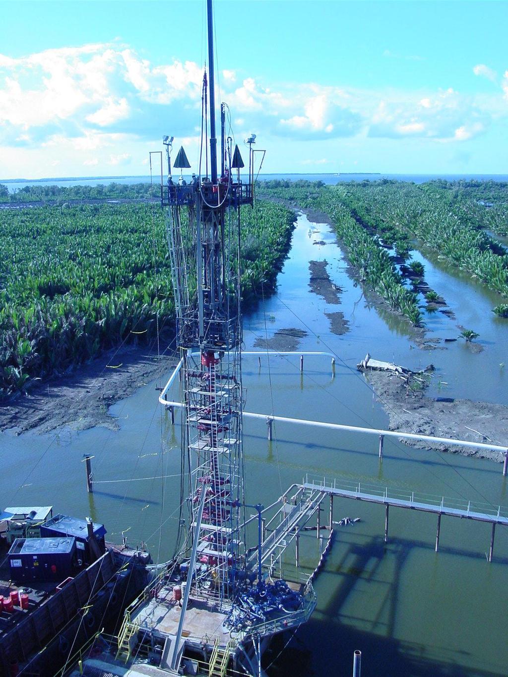
111 Killing a Well During Snubbing Operations Argentina

112 Killing a Well During Snubbing Operations Access Window

113 Killing a Well During Snubbing Operations

114 Killing a Well During Snubbing Operations

115 Killing a Well During Snubbing Operations Unit Anchors

116 Killing a Well During Snubbing Operations Deluge System Test

117 Killing a Well During Snubbing Operations Long Stroke Unit

118 Killing a Well During Snubbing Operations

119 Killing a Well During Snubbing Operations Guide Tube
120 Snubbing Operations Learning Objectives You learned - Various activities suitable for snubbing operations. Best practices and techniques for conducting snubbing operations. The types of snubbing units, components, tools and BOPs. How to handle common problems confronting snubbing operators, and how to handle equations relating to snubbing operations. Minimal safety and control procedures regarding snubbing operations.
121 Snubbing Operations

122 Snubbing Operations
123 Snubbing Operations

124 Snubbing Operations On Dual String Job
125 Snubbing Operations

126 Snubbing Operations Operator s Control Console

127 Snubbing Operations Tubing Guide Support Bracket

128 Snubbing Operations Bell Nipple With Fill-up Line
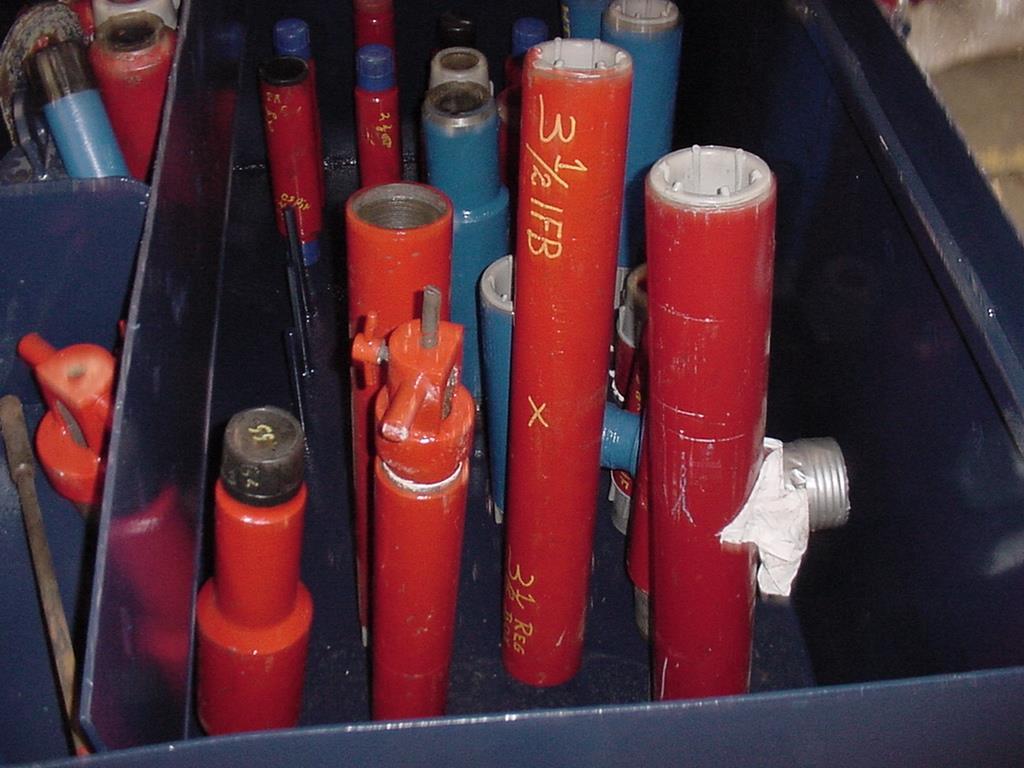
129 Snubbing Operations Tool Baskets

130 Snubbing Operations 600K

131 Snubbing Operations 340K

132 Snubbing Operations Kill Manifold

133 Snubbing Operations Rotary/Power Drive
134 Snubbing Operations
IWCF Equipment Sample Questions (Combination of Surface and Subsea Stack)
") IWCF Equipment Sample Questions (Combination of Surface and Subsea Stack) 1. Given the volumes below, how much hydraulic fluid will be required to carry out the following operations (no safety margin)?
IWCF Equipment Sample Questions (Combination of Surface and Subsea Stack) 1. Given the volumes below, how much hydraulic fluid will be required to carry out the following operations (no safety margin)?
IWCF Equipment Sample Questions (Surface Stack)
") IWCF Equipment Sample Questions (Surface Stack) 1. During a well control operation 4000 psi was shut in below the middle pipe rams. Ram type BOP data: Model: Cameron U type Rated Working Pressure: 15000
IWCF Equipment Sample Questions (Surface Stack) 1. During a well control operation 4000 psi was shut in below the middle pipe rams. Ram type BOP data: Model: Cameron U type Rated Working Pressure: 15000
Casing Design. Casing Design. By Dr. Khaled El-shreef
 Casing Design By Dr. Khaled El-shreef 1 Casing Design CONTENTS Function of Casing Casing Types & Tools Strength Properties Casing Specification Casing Design 2 1 RUNNING AND CEMENTING CASING Reasons for
SPE Coiled Tubing in High-pressure Wells. Well Control Considerations. Introduction
 Society of Petroleum Engineers SPE 24793 Coiled Tubing in High-pressure Wells K.R. Newman and M.G. Allcorn, Dowel1 Schlumberger SPE Members Copyright 1992, Society of Petroleum Engineers Inc. This paper
Subsea Safety Systems
 Subsea Safety Systems The ELSA-HP has been developed to service the high pressure horizontal tree completion and intervention market. With systems designed and qualified up to 15,000 psi, 250 degf and
Hydro-Mech Bridge Plug
 Manual No: 0620000303 Revision: F Approved By: Quality Engineer Date: 2014-9-9 Hydro-Mech Bridge Plug DESCRIPTION: Map Hydro-Mech Bridge Plug is hydraulically actuated and mechanically set. Compact, with
WellCAP IADC WELL CONTROL ACCREDITATION PROGRAM
 WellCAP IADC WELL CONTROL ACCREDITATION PROGRAM WELL SERVICING OPERATIONS (WIRELINE, COILED TUBING & SNUBBING) CORE CURRICULUM AND RELATED FORM WCT-2WSI INTRODUCTORY LEVEL For information on how an course
DB Bridge Plug. Features. Benefits. Applications
 DB Bridge Plug The WELLFIRST Premium Cast Iron Bridge Plug designed to run on electric line. Rated between 2000-10000-psi differential, and 300 F from above and below. Features Field Proven Design Constructed
SCORPION HIGH-QUALITY, FULLY COMPOSITE PLUGS
 SCORPION HIGH-QUALITY, FULLY COMPOSITE PLUGS A DIFFERENT KIND OF ENERGY COMPANY Nine Energy Service isn t your typical oilfield services company. Our success stems from a culture driven by performance
Bridge Plugs, Ball Drop & Caged Ball Plugs For Zone Isolation
 Bridge Plugs, Ball Drop & Caged Ball Plugs For Zone Isolation ADVANTAGE composite bridge plug, caged ball and ball drop (flow thru) frac plug provide a means to isolate multiple zones during high pressure
OPERATING MANUAL DOUBLE ACTING DRILLING INTENSIFIER HYDRAULIC TYPE
 Page 1 of 8 OPERATING MANUAL DOUBLE ACTING DRILLING INTENSIFIER HYDRAULIC TYPE Size Series 6.50" 478 Reviewed And Approved By: Signature: Initials: Date: Page 2 of 8 Section OPERATING MANUAL DOUBLE ACTING
5k Slickline Lightweight Pressure Control Equipment 4 ID
 5k Slickline Lightweight Pressure Control Equipment 4 ID Table of Contents 5k Slickline Lightweight Pressure Control Equipment 4 ID... 1 Hydraulic Slickline Stuffing Box... 3 Wireline Lubricators... 4
North American sealing solutions Bridge Plug Ball Drop Frac Plug Caged Ball Frac Plug
 North American sealing solutions Bridge Plug Ball Drop Frac Plug Caged Ball Frac Plug The North American Sealing Solutions composite bridge plug, caged ball and ball drop (flow thru) frac plug provide
W I L D W E L L C O N T R O L FLUIDS
 FLUIDS Fluids Learning Objectives You will learn about different fluids that can be used in well control. You will become familiar with the characteristics and limitations of fluids. You will learn general
WellCAP IADC WELL CONTROL ACCREDITATION PROGRAM
 WellCAP IADC WELL CONTROL ACCREDITATION PROGRAM WIRELINE OPERATIONS CORE CURRICULUM AND RELATED FORM WCT-2WLF FUNDAMENTAL LEVEL The purpose of the core curriculum is to identify a body of knowledge and
Model A Sleeve Valve Cement Retainer
 Ret. O.D. Model A Sleeve Valve Cement Retainer DIMENSIONAL DATA A B C D E F G H J K L M N P Q R 3.593 3.593 3.500 2.500 3.531 3.531 1.345 3.375.750.437 2.437 2.187 7.062 2.437 5.312 11.685 20.093 3.937
OCEAN DRILLING PROGRAM
 BIH OCEAN DRILLING PROGRAM www.oceandrilling.org Scientifi c Application Packers A packer is an inflatable rubber element that inflates to seal the annular space between the drill string and the borehole
Practice Exam IADC WellSharp Driller and Supervisor
 Workover & Completion Day 4 1. In a workover operation of a shut in well a Lubricator is being used together with a Wireline BOP / Wireline Valve. Which Barrier is classified as the Primary Barrier? A.
W I L D W E L L C O N T R O L CIRCULATION & WELL CONTROL
 CIRCULATION & WELL CONTROL Learning Objectives You will learn: The importance of pump rates and pressures during well control operations Pressure relationships Basic calculations necessary in well control
Deepwater Horizon Incident Internal Investigation
 Not all Information has been verified or corroborated. Subject to review based on additional information or analysis. Deepwater Horizon Incident Internal Investigation 1 Areas of Discussion Investigation
Blowout during Workover Operation A case study Narration by: Tarsem Singh & Arvind Jain, OISD
 1. Introduction An incident of gas leakage from a well took place during workover operations. Subsequently, the gas caught fire on the fourth day in which twelve persons were injured. Two contract workers,
APPENDIX A1 - Drilling and completion work programme
 APPENDIX A1 - Drilling and completion work programme Information about the well and drilling To the extent possible, the international system of units (SI) should be adhered to, and the drilling programme
WellCAP IADC WELL CONTROL ACCREDITATION PROGRAM
 WellCAP IADC WELL CONTROL ACCREDITATION PROGRAM WELL SERVICING OPERATIONS SNUBBING CORE CURRICULUM AND RELATED FORM WCT-2SS SUPERVISORY LEVEL The purpose of the core curriculum is to identify a body of
TAM Single SeT inflatable
 TAM Single SeT inflatable ReTRievAble PAckeRS Sets with pressure only Releases with straight pull or rotate Ideal for horizontal applications Sets in casing or open hole Runs on tubing, coiled tubing,
VOLUMETRIC METHODS and STRIPPING OPERATIONS
 VOLUMETRIC METHODS and STRIPPING OPERATIONS WELL CONTROL SCHOOL Muscat, Oman Training Center VOLUMETRIC METHODS and STRIPPING OPERATIONS The material contained here, is based on the best sources available
W I L D W E L L C O N T R O L COMPLICATIONS
 COMPLICATIONS Complications Learning Objectives You will learn to detect changes that deviate from established trends. You will learn how to respond to problems such as: Pump problems String problems Hole
W I L D W E L L C O N T R O L SHUT-IN PROCEDURES
 SHUT-IN PROCEDURES Shut-in Procedures Learning Objectives You will learn general shut-in procedures: For surface BOPs. For subsea BOPs. You will learn to interpret shut-in pressures and be able to perform
DAY ONE. 2. Referring to the last question, what mud weight would be required to BALANCE normal formation pressure?
 DAY ONE 1. Normal formation pressure gradient is generally assumed to be: A..496 psi/ft B..564 psi/ft C..376 psi/ft D..465 psi/ft 2. Referring to the last question, what mud weight would be required to
1. The well has been shut in on a kick and the kill operation has not started.
 Well Control Methods Day 2 1. The well has been shut in on a kick and the kill operation has not started. Shut in drill pipe pressure Shut in casing pressure 500 psi 700 psi After stabilization, both pressures
Offshore Managed Pressure Drilling Experiences in Asia Pacific. SPE paper
 Offshore Managed Pressure Drilling Experiences in Asia Pacific SPE paper 119875 Authors: Steve Nas, Shaun Toralde, Chad Wuest, SPE, Weatherford Solutions Sdn Bhd, SPE, Weatherford Indonesia SPE, Weatherford
W I L D W E L L C O N T R O L COMPLETIONS AND WORKOVERS
 COMPLETIONS AND WORKOVERS Completions & Workovers Learning Objectives You will learn - The reasons why a well needs to be worked over. The benefits derived from working a well over. To prepare a well completion.
On-Off Connector Skirt
 On-Off Connector Skirt Retrievable Packers & Accessories The On-Off Connector Skirt is compact, reliable, fully sealing, J-type tubing disconnect device that automatically engages and releases with a small
HPHT Annular Casing Packer. Obex Annular Casing Packer
 HPHT Annular Casing Packer Obex Annular Casing Packer Industry Challenge Casing packer to support second stage cement Reduce hydrostatic pressure on formation Get cement to surface Annular gas migration
Inflatable Packer Single & Double. Single & Double Packer Dimension. Wireline Packer. Water Testing Packer (WTP) Packer
 Packer") Inflatable Packer Single & Double Single & Double Packer Dimension Wireline Packer Water Testing Packer (WTP) Packer Packer Working Pressure & Depth Chart Packer Water Hand Pump Packer Air Driven Pump
Inflatable Packer Single & Double Single & Double Packer Dimension Wireline Packer Water Testing Packer (WTP) Packer Packer Working Pressure & Depth Chart Packer Water Hand Pump Packer Air Driven Pump
Engineered solutions for complex pressure situations
 SPECIAL SERVICES Engineered solutions for complex pressure situations Cudd Energy Services (CES) delivers custom engineered solutions to resolve complex pressure situations resulting from equipment failure
Pasquale Imbò e Marco Pelucchi ENI S.pA;
 7th European Gas Well Deliquification Conference Innovative Failsafe Capillary Injection System Resolves Liquid Loading in Gas Well with a Cost- Effective Solution that Maintaining Production and Well-Safety
SUPPLEMENT Well Control for Drilling Operations Workover & Completion for Drillers Core Curriculum and Related Learning Objectives
 SUPPLEMENT Well Control for Drilling Operations Workover & Completion for Drillers Core Curriculum and Related Learning Objectives Form WSP-02-DO-SU-WOC-D Revision 0 13 February 2015 DC 2015 COPYRGHT PROTECTED
Restoring Fluid Flow in Tubing Strings
 Restoring Fluid Flow in Tubing Strings Andrew Roth, Product Manager Fike Corporation Fike Hydraulic Tubing Drains (HTD) for use with deep hole drilling tools, downhole devices and other oil and off shore
W I L D W E L L C O N T R O L PRESSURE BASICS AND CONCEPTS
 PRESSURE BASICS AND CONCEPTS Pressure Basics and Concepts Learning Objectives You will be familiarized with the following basic pressure concepts: Defining pressure Hydrostatic pressure Pressure gradient
Wellwork Chronological Regulatory Report
 Well Name: UNIVERSITY 49 #0808H Field: Lin (Wolfcamp) S/T/R: / / County, State: Location Desc: Operator: Enduring Resources, LLC Project Type: Completion District: Southern Project AFE: DV02151 AFE's Associated:
Success Paths: A Risk Informed Approach to Oil & Gas Well Control
 API Winter E&P Standards Conference, Austin January 18, 2017 Success Paths: A Risk Informed Approach to Oil & Gas Well Control Dr. Dan Fraser Director, Strategic Alliances for Global Energy Solutions,
Rig Math. Page 1.
 Page 1 The Calculator and Main Keyboard Display Numerical 10-key pad used for entering numerical values Trigonometric Functions These keys will be used where wellbore angle is an issue These are the keys
Successful Deployment of a Long Gun String Via Intelligent Coiled Tubing
 Successful Deployment of a Long Gun String Via Intelligent Coiled Tubing Parry Hillis: Technical Manager BakerHughes David Ayre: BP Well Perforation Specialist Jim Gilliat: TCP/DST Business Development
Best Practices - Coiled Tubing Deployed Ball Drop Type Perforating Firing Systems
 Best Practices - Coiled Tubing Deployed Ball Drop Type Perforating Firing Systems As a result of a recent job incident utilizing a Ball Drop Type firing system deployed on coiled tubing, the following
BP SIT Testing Franks Facility Lafayette
 BP SIT Testing Franks Facility Lafayette General Information Status: Franks test well Lafayette La. Rig: Franks Test Rig Casing: 13 3/8, 0 to 4,600 Workstring: 4 ½ IF Brine: Fresh Water Directional: Straight
RPSEA UDW Forum June 22 & 23, Secure Energy for America
 RPSEA UDW Forum June 22 & 23, 2010 Secure Energy for America PROJECT TEAM RPSEA Operator Advisory Committee Anadarko Chevron Shell ConocoPhillips Subcontractors IntecSea NOV CTES General Marine Contractors
6-3/4 DUAL PORTED PBL BYPASS SYSTEM (Applicable to sizes 6-1/4 & 6-1/2 also)
") RECEIVING PBL AT RIG SITE TITLE: Operating Instructions for -3/4 PBL -3/4 DUAL PORTED PBL BYPASS SYSTEM (Applicable to sizes -1/4 & -1/2 also) OPERATING INSTRUCTIONS 1. On receipt of PBL Bypass Tools at
RECEIVING PBL AT RIG SITE TITLE: Operating Instructions for -3/4 PBL -3/4 DUAL PORTED PBL BYPASS SYSTEM (Applicable to sizes -1/4 & -1/2 also) OPERATING INSTRUCTIONS 1. On receipt of PBL Bypass Tools at
SUPPLEMENT Well Control for Drilling Operations Workover & Completion for Supervisors Core Curriculum and Related Learning Objectives
 SUPPLEMENT Well Control for Drilling Operations Workover & Completion for Supervisors Core Curriculum and Related Learning Objectives Form WSP-02-DO-SU-WOC-S Revision 0 13 February 2015 DC 2015 COPYRGHT
Well Control Drill Guide Example Only. Drill Guide is the list of drills, questions and attributes that are in DrillPad.
 Well Control Drill Guide Example Only Drill Guide is the list of drills, questions and attributes that are in DrillPad. This Well Control Drill Guide will be used in conjunction with the rig-specific well
VortexFlow DX (Downhole) Tool Installation Instructions
 Tool Installation Instructions") VortexFlow DX (Downhole) Tool Installation Instructions www.vortextools.com Page 1 of 10 The VortexFLOW tools are based upon Technology that is a result of U.S.A. patents 6,151,751; 6,659,118; 6,749,374;
VortexFlow DX (Downhole) Tool Installation Instructions www.vortextools.com Page 1 of 10 The VortexFLOW tools are based upon Technology that is a result of U.S.A. patents 6,151,751; 6,659,118; 6,749,374;
TECHNICAL BENEFITS OF CJS / RAISE HSP. Technical Advantages
 TECHNICAL BENEFITS OF CJS / RAISE HSP Technical Advantages The HSP is designed for low- to mid- volume applications at flow rates of 1 cubic meter to 30 c. m per day. The benefits are in the details. The
Dilution-Based Dual Gradient Well Control. Presented at the 2011 IADC Dual Gradient Workshop, 5 May 2011 by Paul Boudreau, Dual Gradient Systems LLC
 Dilution-Based Dual Gradient Well Control Presented at the 2011 IADC Dual Gradient Workshop, 5 May 2011 by Paul Boudreau, Dual Gradient Systems LLC In this very short presentation, we will Review Dilution-based
Float Equipment TYPE 925/926
 Type 925 Float Collar Plunger Valve Float Equipment For less demanding well conditions, such as shallower depths or lower pressures, Top- Co offers economical float equipment certified to API RP 10F category
Study Guide IADC WellSharp Driller and Supervisor
 Times to Flow Check: Before pulling out of the hole Before pulling BHA into the BOP When bit is pulled into the casing Increase in cuttings at shakers with same ROP On connections Upon abnormal trip tank
PROPOSED NEW SUB- CODE 1 RIG UP AND TEAR. Possibly Fits into Existing Code. 7/26/2018 Review PROPOSED NEW CODE EXISTING OPERATION
 NW NW 1 RIG UP AND TAR 1 no sub-code RIG UP AND TAR DOWN Start: Rig released from previous well, nd: Rig fully rigged up, acceptance tests successfully completed, and signed off. DOWN 1 1 Rig Under Tow
Standard Operating Procedures
 Standard Operating Procedures GlassBore and GlassLine EUE 8RD Tubular Goods Composite Lining Systems Focus on Safety and Quality COMPOSITE LINING SYSTEMS Table of Contents Section 1 page 3 Arrival on Production
PHE KE30-A8 WORKOVER PROGRAM
 PHE WMO KE30-A8 WORKOVER PROGRAM PHE KE30-A8 WORKOVER PROGRAM Prepared by: Ross Webber. Hendra Wahyudi. Chandra Maulana. George Lattimore Adi Benanjaya Achmad Soendaroe. Tri Wiyono DRILLING ENGINEER SR.
Investigation of Loss of Well Control Eugene Island Block 277 OCS-G Well A-2 Off the Louisiana Coast July 6, 2001
 OCS Report MMS 2002-040 Investigation of Loss of Well Control Eugene Island Block 277 OCS-G 10744 Well A-2 Off the Louisiana Coast July 6, 2001 U.S. Department of the Interior Minerals Management Service
Appendix K Appendix K
 Appendix K BOP Leaks There were five minor leaks in the Deepwater Horizon BOP control system: three were identified after the BOP stack was latched to the wellhead in February 2010, and two were identified
2-7/8 TRIPLE PORTED PBL BYPASS SYSTEM
 RECEIVING PBL AT RIG SITE TITLE: Operating Instructions for 2-7/8 Triple Port PBL 1-10-201 2-7/8 TRIPLE PORTED PBL BYPASS SYSTEM OPERATING INSTRUCTIONS 1. On receipt of PBL Bypass Tools at Rig site, the
SURFACE CASING SELECTION FOR COLLAPSE, BURST AND AXIAL DESIGN FACTOR LOADS EXERCISE
 SURFACE CASING SELECTION FOR COLLAPSE, BURST AND AXIAL DESIGN FACTOR LOADS EXERCISE Instructions Use the example well data from this document or the powerpoint notes handout to complete the following graphs.
Squeeze Cementing. Brett W. Williams Cementing Technical Advisor January 2016 Tulsa API Meeting
 Squeeze Cementing Brett W. Williams Cementing Technical Advisor January 2016 Tulsa API Meeting Definition Squeeze Cementing is the process of applying hydraulic pressure to force or squeeze a cement slurry
International Well Control Forum. Well Intervention Pressure Control Level 2 Syllabus July 2015 Version 7.0
 International Well Control Forum Well Intervention Pressure Control Level Syllabus July 01 Version 7.0 Well Intervention Pressure Control Syllabus - Level Contents Guidance Notes... 1. OVERVIEW... 1.1.
Air Operated Hydraulic Pumping Systems to 50,000 psi
 High Pressure Equipment Air Operated Hydraulic Pumping Systems to 50,000 psi PS-10: 10,000 psi PS-20: 20,000 psi PS-30: 30,000 psi PS-40: 40,000 psi PS-50: 50,000 psi PS-90: 90,000 psi High Pressure air
Coiled Tubing string Fatigue Management in High Pressure Milling Operation- Case Study
 Coiled Tubing string Fatigue Management in High Pressure Milling Operation- Case Study Abstract: Paper Presenter: Ebrahim Rabbani 1 e.rabbani@mehranservices.com Ebrahim Rabbani, Danial Davoodi 2, Fatemeh
Packer-Type Gas Separator with Seating Nipple
 8 th Annual Sucker Rod Pumping Workshop Renaissance Hotel Oklahoma City, Oklahoma September 25-28, 2012 Packer-Type Gas Separator with Seating Nipple Jim McCoy Lynn Rowlan, Dieter Becker, Ken Skinner -
Cased-Hole Logging Environment
 Cased-Hole Logging Environment 2 Planning a Production Logging Job Planning is an important part of a production logging job. Frequently these jobs can only be done in safety during daylight. Thus, the
Perforating Options Currently Available in Horizontal Shale Oil and Gas Wells. Kerry Daly, Global BD Manager- DST TCP
 MENAPS 2013 Perforating Options Currently Available in Horizontal Shale Oil and Gas Wells Kerry Daly, Global BD Manager- DST TCP MENAPS 13-17 WELL FLOW MANAGEMENT TM Scope/ Contents: MENAPS 13-17 Study
Completion Workover Riser System. Enabling efficient operations by reducing interface complexities and minimizes operational risk
 Completion Workover Riser System Enabling efficient operations by reducing interface complexities and minimizes operational risk Well integrity with fatigue management were key drivers for our system design
float equipment OPERATING MANUAL TYPE 505/506 Float Equipment 1. INFORMATION & RECOMMENDATIONS Float Equipment
 Contents 1. GENERAL INFORMATION & RECOMMENDATIONS 1 2. INSTALLATION FLOAT EQUIPMENT 2 2.1 PRE-USE FIELD INSPECTION 2 2.2 POSITION FLOAT ON CASING STRING 3 3. RUNNING OF FLOAT EQUIPMENT 3 3.1 CIRCULATION
ENDEAVOR ENERGY RESOURCES
 ENDEAVOR ENERGY RESOURCES Lease WELL NO FIELD PBTD PERFORATIONS FOREMAN TOOLPUSHER API NUMBER DATE University 5-20-21 #1H 14,223' Tony Cody 07/02/13 OART WEATHER FLUID SUMMARY W/O UNIT DATA W/L UNIT DATA
Performance and Value of the invision System : Offshore in Coiled Tubing Operations
 Performance and Value of the invision System : Offshore in Coiled Tubing Operations Case Study #0004 Date November 01 21, 2017 Location Gulf of Mexico, Deep Water Introduction Intelligent Wellhead Systems
Introduction to Through Tubing Rotary Drilling
 Introduction to Through Tubing Rotary Drilling By: LEAding Edge Advantage International Ltd Old Stoneywood Church Bankhead Road Bucksburn, Aberdeen AB21 9HQ Tel 44-1224-716969 Fax 44-1224-712333 Email:
BENEDUM (DEVONIAN, GAS) API # UPTON COUNTY, TX DRILLING PERMIT # DAILY REPORTS
 API # UPTON COUNTY, TX DRILLING PERMIT # DAILY REPORTS") 11/17/2011 11/18/2011 11/19/2011 AFE dated 11/18/2011 - pull tbg out of hole and make a mill run. Run packer on tbg and attempt to reestablish production from Devonian Formation. MIRU Great Basin Pulling
11/17/2011 11/18/2011 11/19/2011 AFE dated 11/18/2011 - pull tbg out of hole and make a mill run. Run packer on tbg and attempt to reestablish production from Devonian Formation. MIRU Great Basin Pulling
BLACK HILLS PLATEAU PRODUCTION COMPANY
 BLACK HILLS PLATEAU PRODUCTION COMPANY DRILLING PROGRAM Homer Deep Unit 9 11CH SHL: 300 FNL, 200 FWL, NWNW Sect. 9 T8S R98W BHL: 1350 FSL, 2100 FEL NWSE Sect. 15 T8S R98W Garfield & Mesa Counties, Colorado
BUTTERFLY VALVES Series 800
 BUTTERFLY VALVES Series 800 WARNING Before proceeding read ALL instructions and become familiar with the equipment and associated drawings. Follow ALL applicable safety regulations and codes for pressurized
NeoProducts, LLC 1201 Dealers Ave. Harahan, LA Ph:
 Please read this entire document. It concerns all 9⅝ Vented Thru-tubing Bridge Plugs Read this document before proceeding to NeoProducts Recommended Best Practices for 9⅝ vented T- TBPs. Whenever running
Chapter 5 Drilling and Well Testing Practices
 Chapter 5 Drilling and Well Testing Practices Drilling and Well Testing Practices Activities in rotary drilling, completing, testing and maintaining a well. Health and safety requirements shall be covered
HydroPull. Extended-Reach Tool. Applications
 Extended-Reach Tool HydroPull This tool incorporates a cycling valve that momentarily interrupts the flow to create water-hammer pressure pulses inside coiled or jointed tubing used in horizontal well
The topics I will briefly cover, are; Stack Configurations Wellhead Connector Considerations Control Systems Tensioning Systems will be discussed by
 Thank you Greg. 1 The topics I will briefly cover, are; Stack Configurations Wellhead Connector Considerations Control Systems Tensioning Systems will be discussed by Mr. Muhammad Sadiq, however in short,
Retrievable Bridge Plugs
 Retrievable Bridge Plugs & Associated Equipment Well Intervention omega-completion.com Our Philosophy High performance and integrity The Omega range of Retrievable Bridge Plugs and our accompanying suite
WHEATLEY WHEATLEY SERIES 500 SWING CHECK VALVE. Installation, Operation and Maintenance Manual
 WHEATLEY SERIES 500 SWING CHECK VALVE STANDARD INTEGRAL SEAT & OPTIONAL REMOVABLE SEAT 2" FP - 6" FP 150# - 1500# 8" FP - 12" FP 150# - 900# API 6D and B16.34 2" FP - 4" FP 5000# DRILLING PRODUCTION VALVE
Understanding pressure and pressure
 CHAPTER 1 1-1 PRESSURE BASICS Remember to think downhole. The concepts provided in this section cover the foundations for good well control. Understanding pressure and pressure relationships is important
Why Do Not Disturb Is a Safety Message for Well Integrity
 Why Do Not Disturb Is a Safety Message for Well Integrity Presented at the Practical Well Integrity Conference 9-10 December, 2014 in Houston By Ron Sweatman, Principal Advisor, Reservoir Development Services,
The Time Has Come For Coiled Rod. Reprinted from Well Servicing magazine
 The Time Has Come For Coiled Rod Reprinted from Well Servicing magazine The development of flush-by well service units and stand-alone coiled rod injector head technology has helped grow the coiled rod
Type 967 Diamond Broaching Type 968 Sidewinder reamer shoe
 Type 965 float collar Type 966 float shoe 1. GENERAL INFORMATION & RECOMMENDATIONS Type 967 Diamond Broaching Type 968 Sidewinder reamer shoe Type 969 Sidewinder reamer shoe Float Equipment Top-Co Float
The key to connectivity
 The key to connectivity Kerry Daly, Global BD Manager, Tubing Conveyed Perforating (TCP) First published by Oilfield Technology, November 2015 Connecting oil or gas-bearing formations with the wellbore
The Developing Design of the Blowout Preventer in Deep Water
 The Developing Design of the Blowout Preventer in Deep Water IADC World Drilling 2011 Conference & Exhibition 15-16 June 2011, Bella Centre, Copenhagen Eric Brown Project Manager National Oilwell Varco
Exercise 2-3. Flow Rate and Velocity EXERCISE OBJECTIVE C C C
 Exercise 2-3 EXERCISE OBJECTIVE C C C To describe the operation of a flow control valve; To establish the relationship between flow rate and velocity; To operate meter-in, meter-out, and bypass flow control
Abandonment Program for Paramount Fort Liard F 36
 Abandonment Program for Paramount Fort Liard F 36 Well Name: Paramount et al Liard F 36 Area: 60 0 10 N, 123 0 15 W Location: Latitude: 60 0 05 27 Longitude: 123 0 22 00 UWI: 300F366010123150 WID: 1841
Oman Central Gas Velocity Strings in deep tight gas wells. September th European Conference on Gas Well Deliquification.
 Oman Central Gas Velocity Strings in deep tight gas wells September 2009-4th European Conference on Gas Well Deliquification. Velocity Strings Oman Central Gas Agenda: - Objectives - Completions - VS design
August 21, Deepwater MPD / PMCD
 August 21, 2011 Deepwater MPD / PMCD Managed Pressure Drilling (MPD) Pressure held on top of riser while drilling. Drill in overbalance condition Pressurized Mud Cap Drilling (PMCD) Pressure of mud column
API Std 53 - Blowout Prevention Equipment Systems for Drilling Wells Standard Edition Section Inquiry # Question Reply
 API Std - Blowout Prevention Equipment Systems for Drilling Wells Standard Edition Section Inquiry # Question Reply Last update: August 12, 2015 Question 1: In reference to API Standard requirement 4.4.3,
INTERMEDIATE CASING SELECTION FOR COLLAPSE, BURST AND AXIAL DESIGN FACTOR LOADS EXERCISE
 INTERMEDIATE CASING SELECTION FOR COLLAPSE, BURST AND AXIAL DESIGN FACTOR LOADS EXERCISE Instructions Use the example well data from this document or the powerpoint notes handout to complete the following
Live well deployment of long perforating gun system using combined CT technologies
 Live well deployment of long perforating gun system using combined CT technologies SPE ICoTA European Well Intervention Conference Aberdeen - 12 November, 2014 Simon Smith, Technical Support Manager Baker
Worked Questions and Answers
 Worked Questions and Answers A Learning Document for prospective Candidates For the Rotary Drilling Well Control Test Programme Copyright, IWCF June 2000 Revision No.1, November 2000 IWCF 2000 page 1 of
Instruction Manual Updated 7/26/2011 Ver. 2.2
 4-Unit Model MB HTHP Filter Press #171-50-4: 115-Volt #171-51-4: 230-Volt Instruction Manual Updated 7/26/2011 Ver. 2.2 OFI Testing Equipment, Inc. 11302 Steeplecrest Dr. Houston, Texas 77065 U.S.A. Tele:
MOCS. Multiple Opening Circulation Sub. Fluid Bypass Valve
 MOCS Multiple Opening Circulation Sub Fluid Bypass Valve 1 Applications BHA Protection o o Pumping LCM Spotting Acid Work-over and completions o o o Well bore cleanout Fluid displacements Bottoms-up circulation
Drilling Efficiency Utilizing Coriolis Flow Technology
 Session 12: Drilling Efficiency Utilizing Coriolis Flow Technology Clement Cabanayan Emerson Process Management Abstract Continuous, accurate and reliable measurement of drilling fluid volumes and densities
Case studies from classes led by Dr. Ron Fulbright, University of South Carolina Upstate. IMPROVED BLOWOUT PREVENTER
 INNOVATIVE ANALYSIS IMPROVED BLOWOUT PREVENTER 1. BRIEF DESCRIPTION OF THE SITUATION The blowout preventer (BOP) is a valve assembly usually mounted on the sea floor at the mouth of an oil well to control