Standard Operating Procedure. For. PVD E-Beam
|
|
|
- Baldric Fletcher
- 5 years ago
- Views:
Transcription

1 P a g e 1 Standard Operating Procedure For PVD E-Beam
2 P a g e 2 Introduction The PVD Electron-Beam Evaporator (E-Beam) thin film deposition machine uses a magnetically guided and collimated stream of electrons generated by applying high voltage to a large tungsten filament to heat, melt and vaporize materials in a vacuum chamber. This vaporized material streams out from the source and is deposited on all surfaces within line of sight in the chamber. At present only metals can be deposited using the PVD but in theory anything that can be melted and vaporized can be deposited. The E-beam has the advantage of being able to achieve high deposition rates and thicker films because of its large supply of deposition material in the chamber. The substrate receiving the film is far removed from the energies of the vapor source and so the deposition process is gentler on the sample. The process does, however, require a relatively high quality vacuum and so extended pump-down times are required any time the main chamber is opened to change the source material. Reservations are required at least 24 hours in advance for the machine and any new material not on the deposition list must be pre- approved. Deposition materials are typically loaded, refilled and cleaned for the day between 8 and 9 am; after materials loading, the chamber will typically be ready for use by 10 am. Safety considerations The e-beam is designed safely with interlocks that protect the user and machine, however if proper procedures are not followed there are risks to the user, the users materials and the machine. There are open moving parts, heavy hatches, hot surfaces, and intensely bright light sources that can cause injury; and actions are required in specific sequence so as to not cause injury and or damage. It is the responsibility of the user to follow all current procedures and failure to do so will incur additional cost to the user should there be a mishap. Always use this SOP while processing as updates and changes in procedure will always be current here. Altering the recipes beyond the evaporation run time can severely damage loaded devices and should only be done after consultation with staff. Alteration of any calibration settings, ramp times and crystal monitor settings can only be accomplished by staff. After long intense runs the substrate can be hot; use caution when handling the substrate holder and the holder cannot be removed from the load-lock until it is below 50 C. Visually confirm all crucible and shutter motions to ensure proper alignment and actuations; failure to do so could cause reversible damage to your substrate.


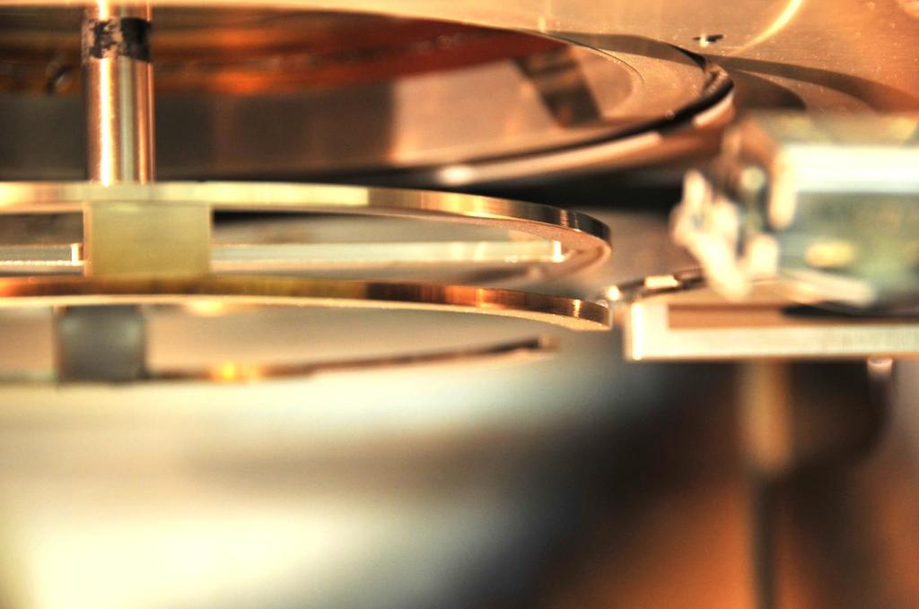
3 P a g e 3 Machine "Anatomy"


4 P a g e 4 Pre-operational Checks and Sign On: Step 1: Make sure that your deposition material has been loaded by checking the Load board. Step 2: Select the Chamber Tab on the PVD Laptop 1. Ensure that the Chamber Ion Gauge Vac 10-7 Torr 2. Ensure that the Load Lock Ion Gauge Vac 10-7 Torr 3. Ensure that the Chamber Cryo is on and is 15K 4. Ensure that the Chamber Cryo Gate Valve is open and Isolation is closed.

5 P a g e 5 5. Check the Interlock lights on the left of the screen and make sure that 1, 2, 3, 5, 9, 10, and 11 are on and 4, 6, 7, and 8 are off. Select the Evaporation Tab. 6. Ensure that the Inficon SQC-310 mode box is set to Auto. 7. If not already connected Click on Connect to Inficon button. 8. The Rate through active layer boxes should populate. Check that the frequency box and the % life box has data not 0 or characters. If there is no data in these boxes then the crystal monitor is not functioning properly and processes will not run. 9. Contact staff to fix this problem.


6 P a g e 6 Step 3: Sign on to the TUMI; you will be required to enter in the total thicknesses of each of the materials you plan to deposit. Step 4: Check that the interlock lights 4 and 7 on the left side of the screen are now lit. Step 5: Select Evaporation Tab 1. Click on the source shutter button to open the shutter that covers the hearth, this ill allow the chamber light to fully illuminate the hearth.


7 P a g e 7 2. Turn on the chamber light so that the hearth can be seen more easily 3. Click Indexer Mode button so it indicates manual. 4. Click the 4 button and watch the motor on the left of the machine drive the hearth feed through to ensure it rotates completely. It should rotate once for each pocket, check the rotary hearth in the chamber and confirm that is moving from pocket to pocket; if it does not rotate properly then repeat several times alternating from #1 to #4. If it fails after several attempts call staff for assistance. Watch the crucibles in the hearth rotate as well if there is any doubt about whether the indexing is correct call staff.

8 P a g e 8 Diagram of Hearth Configuration 5. Change the Indexer mode back to Auto mode, the hearth will automatically return to the last pocket that was selected by the program. 6. Close the source shutter and confirm visually. Powering up the machine: AT THE ELECTRONIC CONTROL RACK


9 P a g e 9 Step 1: Press the Power Supplies Enable button (turns green). Step 2: Turn the Main Power key to on, then press the On button. Step 3: In the High Voltage section press the Reset button.

 Step 5: Once the Air/Cab light is")

10 P a g e 10 Step 4: Check that the VAC/Tank/Aux 1 lights are lit. The Air/Cab interlock light will light after approximately 5 minutes. Wait for this to happen. You can work on sample prep while waiting. ( See page edge tab for this section) Step 5: Once the Air/Cab light is on, press the On button. Do not press lightly; press firmly with no hesitation. Step 6: Ensure the DC/Kilovolts readout shows voltage. Do not change the voltage.


11 P a g e 11 AT SOURCE 1 SECTION Step 7: Move Remote/Loc/Hand toggle to Loc. Step 8: Press the On button. Step 9: Move the Remote/Loc/Hand toggle to Remote. AT THE POWER SUPPLY CONTROLLER Step 10: Set toggle to On.

: Step 1: Ensure that the loader handle")
12 P a g e 12 AT THE LAPTOP Step 11: Check to ensure all the lights, except for the Cryo High Temp, on the left of the screen are on. Start a log entry on the Excel workbook on the desktop. there should be a single line used for each deposition run, a stack of three metals should use three lines! Date time first name last name user number material FTF Xtal life (%) From the Xtal Set Dep rate (A/sec) set thickness indicated thickness measured thickness yy/mm/dd 1300 Nivla Nedgo 4242 Al Loading the sample (See sample preparation guide at the end): Step 1: Ensure that the loader handle is all the way against the right stop.


13 P a g e 13 Look in the chamber and make sure that there is no sample or sample holder loaded on the substrate Z stage. If there is then it will have to be unloaded first. (see removing the sample on pg 22) Step 2: Select the Chamber Tab. 1. Ensure that the isolation valve is closed. 2. Select the Pump Sequence drop down menu and select LoadLock Vent is vented when the load lock chamber reads ~ 7.5 E+2 Torr.. The loadlock Step 3: Once vented, manually open the loadlock door. Be careful, the door is heavy. DO NOT TOUCH THE O-RING.

 Step 10: Open the manual isolation valve completely by turning the crank handle counterclockwise, slight resistance is felt followed by the sound of")
14 P a g e 14 Step 6: Place the properly prepared (see sample prep section) sample holder on the loader arm; the posts on the loader arm (one on the right ant two on the left) should correspond with the slots on the sample carrier. Check to ensure there is there is no debris on the o-ring; if there is debris; clean the o-ring an isopropyl alcohol moistened wiper. Step 7: Close lid gently. Select loadlock pumpdown in Pump Sequence Window and wait for the load lock chamber ion gauge to reach 2.0 x 10⁻⁶ Torr. (lower if the material is reactive with Oxygen) Step 10: Open the manual isolation valve completely by turning the crank handle counterclockwise, slight resistance is felt followed by the sound of the gate snapping open, continue to turn the crank until the white bar appears in the Open Window.

15 P a g e 15 Step 11: Turn on chamber light if not already on. Step 12: Click the Main Tab. Step 13: Visually check to see if the substrate stage is in the load position. If not, then lower the substrate Z stage by clicking the Down button. Step 14: Slide the loader handle to the Chuck Safety Check line.

16 P a g e 16
 until proper alignment is obtained by inputting 2mm into the jog box and clicking the Jog Up.")
17 P a g e 17 Step 15: Ensure that the sample holder will go between the substrate Z upper and lower rings as in the photo above. If it does not, adjust the Substrate Z (in the Main tab) until proper alignment is obtained by inputting 2mm into the jog box and clicking the Jog Up. Repeat if necessary until the proper alignment is reached. Be aware that more precision is required for the clamping small sample holder and or thicker samples. It may be that some samples may only be loaded manually. During this operation, no substrate Z motion is permitted with the loader arm past the safety line. Step 16: Slowly insert the sample holder all the way against the stop. If you feel resistance, visually inspect the sample holder. If further adjustment is needed, return the loader arm to the Safe position and make the proper adjustments. DO NOT FORCE ANYTHING, IT SHOULD BE EASY AND FRICTION FREE MOTION. If there is any mis-alignment or obstructions preventing a safe and proper load then stop return to safety line and call staff. there is ANY resistace to the remoal of the arm, stop and all staff!!! If Step 17: Press the Up button on the Substrate Z holder in the window and watch for the substrate holder to seat properly and clear the arm after picking up the sample holder. One can jog up as well I that is more comfortable. Any time that the Z is in motion the cursor should be hovering over the STOP button so that motion can be stopped instantly if there is a problem.


18 P a g e 18 Step 18: Click Main Tab 1. Ensure that Z is up (light will be on). Step 19: Once clear, move the loader arm to the far right stop. Step 20: Close the manual isolation valve by turning the crank clockwise. When nearly closed a slight resistance is felt during crank rotation followed by the sound of the gate snapping closed, a few more turns to resistance is all that is needed (The white bar appears in the Closed Window)


19 P a g e 19 Running a Process: Go to the chamber tab Step 1: Check that the substrate shutter is closed and the source shutter is closed. Do so by checking for the light on the computer as well as visually through the chamber port hole. If the light is off, the shutter is closed. Step 2: If rotation is not required, skip to Step 3. If you desire substrate rotation, go to the Main tab and enter the RPM set point you prefer (i.e. 10) and click Rotate. If substrate heating is required now is when the heater would be started; please note that heating is Staff programmed and a request must be made at least 24 hours in advance. See the substrate heating section at the end of this document. Step 3: Select the Evaporation Tab. 1. Ensure that the Inficon SQC-310 mode box is set to Auto.


20 P a g e Select proper process number (See Process Assignment Board) 3. Click on Connect to Inficon button if it is not already connected. 4. The Rate through active layer boxes should be populated. Check that the frequency box and the % life box has data not 0 or characters. If there is no data in these boxes then the crystal monitor is not functioning properly and the process will not run. Call staff for assistance. Step 4: Set the desired thickness as follows. 1. Go to Electronics Control Rack 2. Go to SQC-310 deposition controller. 3. Press the Next Menu button until you see Process Menu on the list. 4. Press the Process Menu button. 5. Rotate the selector knob until your process is selected. 6. Press the Edit button


21 P a g e Check that the layer contains the requested deposition material on the display. 8. Select the layer with the knob. 9. Select Edit. 10. Rotate the process knob until Final Thickness is selected. 11. Select Edit. 12. Set final thickness by rotating selector knob to desired set point.


22 P a g e Press Enter. 14. If a different deposition rate is desired then it can be changed in this window, Dep rates over 5A/s are not allowed on any material. Usually the slower the rate the better the film. Discuss any changes to the default dep rate with staff prior to processing as there are many factors that affect the rate. 15. Press To Main button. 16. Press the main menu button until the process and film menu buttons are displayed, press the film menu then select each material to be deposited and confirm that each loaded material is designated with the correct pocket number as indicated on the load board.


23 P a g e 23 AT LAPTOP Step 17: Choose the correct process number by pressing the arrows next to the process number window (the correct process is indicated on the load board for each material) then press Start Process button. NOTE: The Indexer will move to the proper pocket if not already selected. Then the process will start. Turn on the chamber light and open source shutter so that the hearth is well illuminated, Watch the pockets move to the desired material. If I doubt that the proper pocket is not aligned properly in the window then press Stop Process and call or staff assistance. Step 18: Press Zero Thickness button. The process will proceed in the following manner. Indexing phase Film conditioning phase active evaporation phase material cool down and be designated using the following short hand so that one will be able to determine the total process time from beginning to end. percent power / time dwell time percent power / time dwell time evaporation power Evaproation A/sec percent power / time IE: 10 / / / 5 Will increase the power to 10 percent over a 5 minute period and hold it there for five minutes then will proceed to 30 percent power over the next 10 minutes and hold it there for 1 minute then a final ramp to the evaporation power set point at which time the shutters will open and the evaporation controller

24 P a g e 24 will vary the power to achieve rate setpoint, when the desired thickness is reached the shutters will close and the cool down will occur over the next 5 minutes. The phase box will indicate Stopped. Removing the sample: Step 1: Once the shutter closes after the deposition, select the Evaporation Tab. 1. Ensure that the source shutter is closed and open the substrate shutter. Step 2: Select the Chamber Tab. Step 3: Open the manual isolation valve. Step 4: Move the loader arm all the way to the left against the stop. Step 5; Select the Main Tab 1. Select the Down button in the Substrate Z stage box. 2. Move the cursor over the stop button (Do Not Click Yet) and watch the substrate lower on to the loading arm. Watch to make sure the loader arm pins align and seat will with the substrate holder pin holes. If they do not click the Stop button and call for assistance. 3. If there are not issues, click stop once the sample holder is elevated by the loader arm to the center substrate z assembly. Step 6: slide the loader arm all the way to the right against the stop. If ANY resistance or unusual friction is felt stop and visually check for proper adjustment and use the jog buttons to reposition the z holder BY SMALL STEPS until the sample holder if free of contact while removal Step 7: Close the manual isolation valve. (The white bar appears in the Closed Window ) Step 8: Select the Chamber Tab. 1. In the Pump Sequence drop down, select Loadlock Vent. Step 9: Once the chamber pressure reaches ~7.0E+2, carefully lift the loadlock door and remove sample.
25 P a g e 25 Step 10: Close the loadlock door. Step 11: In the Pump Sequence dropdown, select Loadlock Pumpdown. Shutting down the machine: AT THE POWER SUPPLY CONTROLLER Step 1: Set toggle to off. AT THE SOURCE 1 SECTION Step 2: Move Remote/Loc/Hand toggle to Loc. Step 3: Press the Off button. AT THE HIGH VOLTAGE SECTION Step 4: Press the Off button. AT THE MAIN POWER SECTION Step 5: press the OFF button, then turn the Main Power key to the off position. Step 6: Press the Power Supplies Off button. Step 6: Log off TUMI, making any notes that you feel are appropriate.
26 P a g e 26 Wafer and sample prep For whole 4 and 6 inch wafers there are dedicated holders and the wafer will just sit in the depression. For small pieces there is a holder with multiple screw holes and clamps so that many samples may be loaded on one carrier. A word of caution about the clamps on the small sample carrier; if the deposition is going to be long and intense so that the sample holder heats up or if the substrate heater is used there is the possibility that the clamps will loosen and drop the sample, in this case use multiple clamps of consult with staff. If a sample drops into the crucible and contaminates it then the user will be charged for the entire crucible of material. The small sample holder will not be used if there are any open holes; make sure that uncovered screw holes have a screw in them. For alternate methods of securing samples in the machine consult with staff. Fresh clear wafers and samples (No pattern clear substrate) should be thoroughly clean with the oxide stripped if appropriate. Samples that are post lithography should be well developed and residue free in the clear areas and, ideally, be undercut if liftoff is planned after deposition. It is wise to stop by the Asher and O2 clean the cleared features just before loading, be careful not to over clean, 10 seconds should do to remove any residue and over cleaning can remove too much PR and change the pattern. Sample holders can be made out of 4 inch wafers using the dicing machine and then loaded on the 4 wafer holder; custom holders must be designed with staff consultation and approval.


27 P a g e 27 Substrate Heating Note: Substrate heating must be requested 24 hours in advance and all samples, materials and mounting methods must be approved by staff. It is a staff programmed procedure that is initiated by the user at the appropriate time. There may be times, depending on the condition of the chamber that staff will require that a heated process be postponed until after a thorough chamber clean. Substrate heating process; 1 at the electronics rack press the PWR switch on the Heater Controller and allow it to initialize to the Standby mode. 2 Press the Start button so that the POWER indicator lights. 3 At the laptop; select the Main tab and click on the run button under Heater Substrate.
 4 after the deposition is finished and the shutter is closed return to the Heater Substrate")
28 P a g e 28 The substrate heater will go through a preprogrammed heater ramping routine to the requested temperature. Wait for the temperature to stabilize at set point before proceeding with the deposit (return to Step 3) 4 after the deposition is finished and the shutter is closed return to the Heater Substrate window and press Skip; the heater will go through a pre-programmed cool down. 5 The Heated sample will not be removed until it has cooled down to less than 50 C. the progress of the cooling can be monitored on the laptop or the electronic rack. 6 after cool down go the the Removing Sample section.
Issue: H Title: CHA E-Beam Evaporator Page 1 of 7. Table of Contents
 Title: CHA E-Beam Evaporator Page 1 of 7 Table of Contents Purpose/Scope... 2 2.0 Reference Documents... 2 3.0 Equipment/Supplies/Material... 2 4.0 Safety... 2 5.0 Set Up Procedures... 2 5.1 PC Logon and
Operating Procedures for Metal Evaporator I
 Operating Procedures for Metal Evaporator I Metal Evaporator I is intended as a tool and a training device. Understanding the operation of this equipment should give you a basic knowledge of vacuum and
SPUTTER STATION STANDARD OPERATING PROCEDURE
 SPUTTER STATION STANDARD OPERATING PROCEDURE Purpose of this Instrument: This instrument is used for deposition of thin metal or oxide films. Source materials supplied by WVU Shared Research Facilities:
Angstrom E-Beam Instructions. PROCESS CHECKS: the tooling factors of each metal; Ti/Au layer for wire bonding pull test.
 Angstrom E-Beam Instructions Tool Manager: Joe Palmer (jpalmer@princeton.edu) Office: 8-4706; Cell:609-751-1353 Backup: David Barth (dbarth@princeton.edu) Office: 8-4626; Cell: 610-405-8227 PROCESS CHECKS:
Angstrom Dielectric Sputterer Operation Manual
 Angstrom Dielectric Sputterer Operation Manual I. System overview The Angstrom Dielectric Sputterer (ADS) has a similar interface as the Angstrom metal sputterer. It has two screens, the process screen
Cryo-Evaporator Operation
 Cryo-Evaporator Operation Cara Ricci November 25, 2003 Thin Film Deposition THE UNIVERSITY OF TEXAS AT DALLAS ERIK JOHNSON SCHOOL OF ENGINEERING DOCUMENT NUMBER: FA2003-TF-008 EDITION: 1.1 PAGE: 1 of 28
MJB4 Mask Aligner Operating Procedure. Effective Date: 07/12/2012 Author(s): Jiong Hua Phone:
: Jiong Hua Phone:") MJB4 Mask Aligner Operating Procedure Effective Date: 07/12/2012 Author(s): Jiong Hua Phone: 402-472-3773 Email: jhua2@unl.edu 1 1 Introduction 1.1 Key Words Karl Suss MJB4 Mask Aligner, Optical Lithography,
MJB4 Mask Aligner Operating Procedure Effective Date: 07/12/2012 Author(s): Jiong Hua Phone: 402-472-3773 Email: jhua2@unl.edu 1 1 Introduction 1.1 Key Words Karl Suss MJB4 Mask Aligner, Optical Lithography,
Oerlikon Sputtering Evaporator SOP
 Oerlikon Sputtering Evaporator SOP Short UNT Cleanroom 1. Taking out sample holder from Transport Chamber : Log in FOM to access the software Go to the software and log in with user1 and password user1
Temescal BJD-1800 E-Beam Evaporator 1 System Overview - Cryo-pumped for typical base pressures in the low 10e-7 Torr range. - Four pockets in the
 Temescal BJD-1800 E-Beam Evaporator 1 System Overview - Cryo-pumped for typical base pressures in the low 10e-7 Torr range. - Four pockets in the rotating hearth of the electron gun which allows deposition
5.1.3 Mechanical Hazards Drive assemblies have sufficient power to cause injury. Keep hands, fingers, clothing and tools clear of moving parts.
 Approved by: Process Engineer / / / / Equipment Engineer 1 SCOPE The purpose of this document is to detail the use of the PE4400. All users are expected to have read and understood this document. It is
Revised: June 7, 2017
 LC Technologies Thermal Evaporator Standard Operating Procedure Faculty Supervisor: Prof. Robert White, Mechanical Engineering (x72210) Safety Office: Peter Nowak x73246 (Just dial this directly on any
OPERATION OF THE DIMPLER
 OPERATION OF THE DIMPLER After thinning your sample to ~80 μm you can now do a dimpling process to thin the center up to 10 μm. When you walk in and use the DIMPLER it should already be calibrated and
Standard Operating Manual
 Standard Operating Manual Denton Explorer 14 RF/DC Sputter Version 1.0 Page 1 of 11 Contents 1. Picture and Location 2. Process Capabilities 1. Cleanliness Standard 2. Available for Sputtering Materials
Unifilm Technology PVD-300 Sputter Deposition Operation Instructions
 Unifilm Technology PVD-300 Sputter Deposition Operation Instructions Contributors: Devin Brown, Kevin Klein, Ben King, Eric Woods Anything that is BOLD UNDERLINED ITALICS means that you should press that
Standard Operating Manual
 Standard Operating Manual AB-M Mask Aligner Version 1.1 Page 1 of 18 Contents 1. Picture and Location 2. Process Capabilities 2.1 Cleanliness Standard 2.2 Wafer Chuck Selection 2.3 Mask Holder Selection
SSI Solaris 150 RTA Revision /27/2016 Page 1 of 9. SSI Solaris 150 RTA
 Page 1 of 9 SSI Solaris 150 RTA The Solaris 150 RTA is a rapid thermal annealing system capable of handling sample sizes up to 100mm (4 diameter) or smaller. The system can anneal in N 2 and Forming gas
PLASMA ENHANCED CHEMICAL VAPOR DEPOSITION (PECVD) SOP OXFORD PLASMALAB SYSTEM 100
 SOP OXFORD PLASMALAB SYSTEM 100") PLASMA ENHANCED CHEMICAL VAPOR DEPOSITION (PECVD) SOP OXFORD PLASMALAB SYSTEM 100 June 2013 Interface Overview. The Oxford software is divided into 5 main screens. 1) Pump Control page 2) Recipe page 3)
PLASMA ENHANCED CHEMICAL VAPOR DEPOSITION (PECVD) SOP OXFORD PLASMALAB SYSTEM 100 June 2013 Interface Overview. The Oxford software is divided into 5 main screens. 1) Pump Control page 2) Recipe page 3)
Title: Xactix XeF2 Etcher Semiconductor & Microsystems Fabrication Laboratory Revision: A Rev Date: 03/23/2016
 Approved by: Process Engineer / / / / Equipment Engineer 1 SCOPE The purpose of this document is to detail the use of the Xactix XeF2 Etcher. All users are expected to have read and understood this document.
JETFIRST 150 RTA SYSTEM OPERATING MANUAL Version: 2 Feb 2012
 JETFIRST 150 RTA SYSTEM OPERATING MANUAL Version: 2 Feb 2012 UNIVERSITY OF TEXAS AT ARLINGTON Nanofabrication Research and Teaching Facility TABLE OF CONTENTS 1. Introduction....2 1.1 Scope of Work.....2
R I T. Title: STS ASE Semiconductor & Microsystems Fabrication Laboratory Revision: Original Rev Date: 01/21/ SCOPE 2 REFERENCE DOCUMENTS
 Approved by: Process Engineer / / / / Equipment Engineer 1 SCOPE The purpose of this document is to detail the use of the STS ASE. All users are expected to have read and understood this document. It is
Approved by Principal Investigator Date: Approved by Super User: Date:
 Approved by Principal Investigator Date: Approved by Super User: Date: Standard Operating Procedure BNC Commonwealth Dual Ion Beam Deposition System (CDIBS) Version 2010 February 14 I. Purpose This Standard
Scanning Electron Microscope JEOL JSM F
 Scanning Electron Microscope JEOL JSM - 7600F How to Use This Manual You will be promised to obtain successful results if you follow this step by step manual gently and carefully. In order to that, you
1)! DO NOT PROCEED BEYOND THIS MARK
! DO NOT PROCEED BEYOND THIS MARK") Operating Instructions for X-ray Photoelectron Spectrometer: Physical Electronics Model 555 XPS/AES (John H. Thomas, III, Ph.D., Electron Spectroscopy) Sample Insertion: figure 1. Sample insertion rod
Operating Instructions for X-ray Photoelectron Spectrometer: Physical Electronics Model 555 XPS/AES (John H. Thomas, III, Ph.D., Electron Spectroscopy) Sample Insertion: figure 1. Sample insertion rod
Unaxis ICP/RIE SOP Revision 8 09/30/16 Page 1 of 5. NRF Unaxis ICP/RIE Etch SOP
 Page 1 of 5 NRF Unaxis ICP/RIE Etch SOP Unaxis Shuttlelock Reactive Ion Etcher with Inductively Coupled Plasma Module. Etch Capabilities: SiO2, Si3N4, Al, dielectrics and other commonly used materials.
1.1 Equipment: substrate, wafer tweezers, metal targets 1.2 Personal Protective Equipment: nitrile gloves, safety glasses 1.
 Nanomaster NSC-3000 DC Magnetron Sputter Tool Standard Operating Procedure Faculty Supervisor: Prof. Robert White, Mechanical Engineering (x72210) Safety Office: Peter Nowak x73246 (Just dial this directly
Standard Operating Manual
 Standard Operating Manual ARC12M Sputter Copyright 11.2015 by Hong Kong University of Science & Technology. All rights reserved. Page 1 Contents 1. Picture and Location 2. Process Capabilities 2.1 Cleanliness
QUARTZ HOUSING COATING PROCEDURE
 W. W. Hansen Experimental Physics Laboratory STANFORD UNIVERSITY STANFORD, CALIFORNIA 94305-4085 Gravity Probe B Relativity Mission QUARTZ HOUSING COATING PROCEDURE GP-B P0044 Rev- November 18, 1997 Prepared
University of Minnesota, MN Nano Center Standard Operating Procedure
 Equipment Name: HDPCVD Revision Number: 2 Badger Name: HDPCVD Revisionist: L. von Dissen Model: Advanced Vacuum Date: 10/25/2016 Apex SLR ICP Location: PAN, Bay 3 1 Description The Apex SLR ICP is a high
Standard Operating Manual
 Standard Operating Manual Branson IPC 3000 O 2 Asher Copyright 2014 by Hong Kong University of Science & Technology. All rights reserved. Page 1 Contents 1. Picture and Location 2. Process Capabilities
BEST KNOWN METHODS. Transpector XPR3 Gas Analysis System. 1 of 6 DESCRIPTION XPR3 APPLICATIONS PHYSICAL INSTALLATION
 BEST KNOWN METHODS Transpector XPR3 Gas Analysis System DESCRIPTION The Transpector XPR3 is a third-generation, quadrupole-based residual gas analyzer that operates at PVD process pressures and is the
Karl Suss MA6 Mask Aligner SOP
 Page 1 of 11 Karl Suss MA6 Mask Aligner SOP Safety UV Exposure: The high energy light produced by the high pressure Mercury Xenon lamp can cause eye damage and skin burns. Be sure that the light guards
MMRC PVD Evaporator Instructions
 Warnings MMRC PVD Evaporator Instructions (Updated Aug 2016) Under PVD conditions, even oils and greases are volatile. WEAR GLOVES, and if you touch your skin or anything else oily or wet, change them.
March CS-1701F Reactive Ion Etcher
 March CS-1701F Reactive Ion Etcher Standard Operating Procedure Faculty Supervisor: Prof. Robert White, Mechanical Engineering (x72210) Safety Office: Peter Nowak x73246 (Just dial this directly on any
KARL SUSS MJB3 MASK ALIGNER STANDARD OPERATING PROCEDURE
 KARL SUSS MJB3 MASK ALIGNER STANDARD OPERATING PROCEDURE Purpose of this Instrument: This instrument is for patterning photosensitive polymers with UV light. Location: White Hall 410 Cleanroom Primary
NRF Suss Delta 80 Spinner SOP Revision /14/2016 Page 1 of 11. Suss Delta 80 Spinner SOP
 Page 1 of 11 Note: latest updates are blue. Table of Contents Suss Delta 80 Spinner SOP 1.0 Safety 2.0 Quality Controls and Calibration 3.0 Equipment Uses and Restrictions 4.0 Equipment Specifications
Savannah S100 ALD at SCIF, UC Merced Standard operating Procedure
 This document covers the procedure that should be followed for normal operation of the Cambridge NanoTech: Savannah S100 (Atomic Layer Deposition ALD). This tool is design to be used with whole 4inch wafers.
COBILT CA-800 Mask Aligner Equipment Operation
 COBILT CA-800 Mask Aligner Equipment Operation For the Micro-Electronics Laboratory At University of Notre Dame Department of Electrical Engineering This user manual is not be removed from room 247A. This
R I T. Title: Amray 1830 SEM Semiconductor & Microsystems Fabrication Laboratory Revision: A Rev Date: 09/29/03 1 SCOPE 2 REFERENCE DOCUMENTS
 Fabrication Laboratory Revision: A Rev Date: 09/29/03 Approved by: Process Engineer / / / / Equipment Engineer 1 SCOPE The purpose of this document is to detail the use of the Amray 1830 SEM. All users
Notes-PECVD: Chamber 1
 plasmatherm (EML) STANDARD OPERATING PROCEDURE CORAL Name: Plasmatherm Model Shuttlelock System VII SLR-770/734 Number: Location: EML What it Deposits the following films via Plasma-Enhanced Chemical Vapor
Login to ilab Kiosk. Revised 05/22/2018. Load your sample:
 Login to ilab Kiosk Load your sample: 1. Check: The analysis chamber pressure is
Standard Operating Manual
 Standard Operating Manual Branson IPC 3000 O 2 Asher Page 1 of 14 Contents 1 Picture and Location 2 Process Capabilities 2.1 Cleanliness Standard 2.2 Recipes 2.3 Performance of Branson IPC 3000 O 2 Asher
Nanofabrication Facility: PECVD SOP Rev. 00, April 24
 Author: Charlie Yao & Mario Beaudoin Email: charlieyao@gmail.com; Beaudoin@physics.ubc.ca Phone: 604-822-1853(MB). Purpose This document outlines the standard operation for the Trion Plasma Enhanced Chemical
LESKER #1 STANDARD OPERATION PROCEDURE
 Arizona State University NanoFab LESKER #1 STANDARD OPERATION PROCEDURE Rev D Table of Contents Contents Table of Contents...1 1. Purpose / Scope...2 2. Reference Documents...2 3. Equipment / Supplies
University of MN, Minnesota Nano Center Standard Operating Procedure
 Equipment Name: University of MN, Minnesota Nano Center Deep Trench Etcher Badger Name: deeptrench Revision Number: 9 Model: SLR -770 Sofware Version: CORTEX v4.5 Revisionists: Paul Kimani Location: Bay
STS PECVD Instructions
 STS PECVD Instructions I. Introduction A PECVD (Plasma Enhanced Chemical Vapor Deposition) reacts gases in a RF- (Radio Frequency) - induced plasma to deposit materials such as SiO 2 and Si X N Y. This
Usage Policies Notebook for NanoFurnace Furnace (EasyTube 3000 System)
") Usage Policies Notebook for NanoFurnace Furnace (EasyTube 3000 System) Revision date October 2014 2 Emergency Plan for Nano Furnace Standard Operating Procedures for Emergencies Contact information Person
Usage Policies Notebook for NanoFurnace Furnace (EasyTube 3000 System) Revision date October 2014 2 Emergency Plan for Nano Furnace Standard Operating Procedures for Emergencies Contact information Person
Standard Operating Manual
 Standard Operating Manual Karl Suss MA6 Mask Aligner Version 1.1 Page 1 of 24 Contents 1. Picture and Location 2. Process Capabilities 2.1 Cleanliness Standard 2.2 Substrate Size 2.3 Photo Mask Size 2.4
LEO 1525 FEG SEM Standard Operating Procedures Mar. 6, 2012 For additional assistance, please contact the facility manager.
 LEO 1525 FEG SEM Standard Operating Procedures Mar. 6, 2012 For additional assistance, please contact the facility manager. Please contact in case of emergency: SEM microscopist: Mr. Eric Miller, 7-0789
LEO SEM SOP Page 1 of 9 Revision 1.4 LEO 440 SEM SOP. Leica Leo Stereoscan 440i
 LEO SEM SOP Page 1 of 9 LEO 440 SEM SOP Gun (Filament) Column Manual Valves Chamber Window Chamber Stage Movement Leica Leo Stereoscan 440i 1. Scope 1.1 This document provides the procedure for operating
Edge Isolation Tool. Standard Operating Procedure. Version 1.1. Date: Prepared by, Sandeep S S. Department of Electrical Engineering
 Edge Isolation Tool Standard Operating Procedure Version 1.1 Date: 20-9-2012 Prepared by, Sandeep S S Department of Electrical Engineering IIT Bombay This document is meant for internal circulation only
Approved by Principal Investigator Date: Approved by Super User: Date:
 Approved by Principal Investigator Date: Approved by Super User: Date: Standard Operating Procedure BNC OAI 200 Lithographic Mask Aligner (Aligner 3) Version 2011 June 2 I. Purpose This Standard Operating
Equipment Standard Operating Procedure Greg Allion and Kimberly Appel
 Date Created: May 3, 2004 Date Modified: June 1, 2005 MA6/BA6 Mask Aligner Equipment Standard Operating Procedure Greg Allion and Kimberly Appel 1. Purpose 1.1. Photolithography involves transferring a
Approved by Principal Investigator Date: Approved by Super User: Date:
 Approved by Principal Investigator Date: Approved by Super User: Date: Standard Operating Procedure BNC OAI Lithographic Mask Aligner (Aligner 2) Version 2008 October 31 I. Purpose This Standard Operating
Usage Policies Notebook for AMST Molecular Vapor Deposition System MVD 100
 Usage Policies Notebook for AMST Molecular Vapor Deposition System MVD 100 Revision date September 2014 2 Emergency Plan for AMST MVD 100 Standard Operating Procedures for Emergencies Contact information
Nanofabrication Facility: ECR Etcher SOP Rev. 01b, March 06. Standard Operating Procedure for PlasmaQuest ECR II Etching
 Standard Operating Procedure for PlasmaQuest ECR II Etching Authors: Rev. 00: Al Schmalz, Vighen Pacradouni and Jeff Young, December 21, 1998 Rev. 01: Dr. Andras G. Pattantyus-Abraham, May 24, 2005 Rev.
Xactix XeF2 OPERATION MANUAL
 General Information The Xactix e-1 is a xenon difluoride (XeF 2) isotropic silicon etcher. XeF 2 is a vapor phase etch, which exhibits very high selectivity of silicon to photo-resist, silicon dioxide,
ABM MASK ALIGNERS. NanoFab 26 March 2009 A Micro Machining & Nanofabrication Facility
 ABM MASK ALIGNERS LOCATION: Optical Lithography PRIMARY TRAINER: Stephanie Bozic (2-6724, sbozic@ualberta.ca) SECONDARY TRAINER: Jolene Chorzempa (2-4823, jolenec@ualberta.ca) 1. OVERVIEW The ABM Mask
Trion PECVD SOP IMPORTANT: NO PLASTIC, TAPE, RESISTS, OR THERMAL PASTE ARE ALLOWED IN THE CHAMBER
 Trion PECVD SOP IMPORTANT: NO PLASTIC, TAPE, RESISTS, OR THERMAL PASTE ARE ALLOWED IN THE CHAMBER CAUTION: THE CHAMBER PLATE GETS EXTREMELY HOT Start Up Procedure 1) Open bottle and regulator for Helium,
BASIC Z-STACK AND TIME SERIES SCAN ON THE ZEISS LIGHTSHEET Z. 1
 BASIC Z-STACK AND TIME SERIES SCAN ON THE ZEISS LIGHTSHEET Z. 1 The front door of the main body of the instrument may be open when you arrive. Take the sample chamber and slide it into position with the
Plasma Asher: March PX-500 User guide (May-30, 2017)
") Plasma Asher: March PX-500 User guide (May-30, 2017) This is a highly versatile plasma etch tool that can etch using a direct plasma configuration (Oxygen plasma cleaner), a downstream plasma (Remote plasma),
Plasma Asher: March PX-500 User guide (May-30, 2017) This is a highly versatile plasma etch tool that can etch using a direct plasma configuration (Oxygen plasma cleaner), a downstream plasma (Remote plasma),
Plasma-Therm PECVD. Operating Characteristics. Operating Instructions. Typical Processes. I. Loading. II. Operating
 Plasma-Therm PECVD A PECVD (plasma enhanced chemical vapor deposition) reacts gases in a RF (radio frequency) induced plasma to deposit materials such as silicon dioxide and silicon nitride. This PECVD
THERMAL EVAPORATION UNIT (for Al evaporation)
") THERMAL EVAPORATION UNIT (for Al evaporation) System Owner: NeerajPanwar 9619507210 panwar.iitr@gmail.com System Operator: 1. Bhimraj Sable 9930189878 bhimrajsable71@gmail.com Authorized User: 1. Ramesh
THERMAL EVAPORATION UNIT (for Al evaporation) System Owner: NeerajPanwar 9619507210 panwar.iitr@gmail.com System Operator: 1. Bhimraj Sable 9930189878 bhimrajsable71@gmail.com Authorized User: 1. Ramesh
Karl Suss MJB4 Mask Aligner
 Karl Suss MJB4 Mask Aligner Tool Manager: Yong Sun ( yongs@princeton.edu; Office 8-8234; Cell 609-917-5076 ) Backup: George Watson ( gwatson@princeton.edu; Office 8-4626; Cell 732-996-2713 ) ******************************************************************************
KARL SUSS MJB3 UV400 Mask Aligner Standard Operating Procedure
 KARL SUSS MJB3 UV400 Mask Aligner Standard Operating Procedure Version: 1.0 February 2014 UNIVERSITY OF TEXAS AT ARLINGTON Nanotechnology Research Center (NRC) 1 TABLE OF CONTENTS 1 Introduction 3 1.1
Usage Policies Notebook for STS DRIE System
 Usage Policies Notebook for STS DRIE System Revision date September 2014 2 Emergency Plan for STS DRIE System Standard Operating Procedures for Emergencies Contact information Person Lab Manager Director
Nordiko Metal Sputtering System Standard Operating Procedure
 Nordiko Metal Sputtering System Standard Operating Procedure Specifications : Target Size Gases used in the system Base pressure Sputtering pressure Substrates used Substrate size : 2 inch or 4 inch :
O P E R ATING INSTRUCTIONS FOR MODEL SPR-45 Automatic Screen and Stencil Printer
 O P E R ATING INSTRUCTIONS FOR MODEL SPR-45 Automatic Screen and Stencil Printer TABLE OF CONTENTS I. SPECIFICATIONS...3. II. SAFETY INSTRUCTIONS...4. III. INSTALLATION...5. IV. SET-UP...6. V. SYSTEM OPERATION...9.
Usage Policies Notebook for Xenon Difluoride (XeF 2 ) Isotropic Si Etch
 Isotropic Si Etch") Usage Policies Notebook for Xenon Difluoride (XeF 2 ) Isotropic Si Etch Revision date September 2014 2 Emergency Plan for XeF 2 Si Etcher Standard Operating Procedures for Emergencies Contact information
Usage Policies Notebook for Xenon Difluoride (XeF 2 ) Isotropic Si Etch Revision date September 2014 2 Emergency Plan for XeF 2 Si Etcher Standard Operating Procedures for Emergencies Contact information
Misaligned Folds Paper Feed Problems Double Feeds Won t Feed FLYER Won t Run iii
 Operator s Manual Table of Contents Operator Safety... 1 Introduction... 2 Unpacking and Setup... 3 Unpacking... 3 Setup... 4 FLYER Overview... 5 FLYER Diagram... 5 Capabilities... 5 Control Panel... 6
The SPI Sputter Coater Handbook
 The SPI Sputter Coater Handbook Coating of Specimens SPI-Module Sputter Coater with Etch Mode 1. Mount the specimens onto the SEM stub. Keep in mind that many adhesives have high vapor pressure solvents
Warnings: Notes: Revised: October 5, 2015
 Karl Suss MA6 Mask Aligner Standard Operating Procedure Faculty Supervisor: Prof. Robert White, Mechanical Engineering (x72210) Safety Office: Peter Nowak x73246 (Just dial this directly on any campus
QUORUM TECH 150RES THE FIRST AND THIRD WEEK WILL BE SET UP FOR CARBON COATING THE SECOND AND LAST WEEK WILL BE SET UP FOR GOLD COATING
 QUORUM TECH 150RES This document is intended to describe the function and use of the QuorumTech Q150RES system. Formal training and qualification by staff is required before gaining access to the tool.
Warnings: Notes: Revised: January 8,
 OAI Model 204IR Mask Aligner Standard Operating Procedure Faculty Supervisor: Prof. Robert White, Mechanical Engineering (x72210) Safety Office: Peter Nowak x73246 (Just dial this directly on any campus
Operating Procedures for the. SAMCO ICP RIE System
 Operating Procedures for the SAMCO ICP RIE System General Overview: The purpose of the SAMCO Model 200iP Inductively Coupled Plasma Reactive Ion Etcher (ICP RIE) is to etch III-V compound semiconductors
OXFORD PLASMALAB 80PLUS (CLOEY)
") Arizona State University NanoFab OXFORD PLASMALAB 80PLUS (CLOEY) Rev D Table of Contents Contents Table of Contents...1 1. Purpose / Scope...2 2. Reference Documents...2 3. Equipment / Supplies / Material...2
Arizona State University NanoFab OXFORD PLASMALAB 80PLUS (CLOEY) Rev D Table of Contents Contents Table of Contents...1 1. Purpose / Scope...2 2. Reference Documents...2 3. Equipment / Supplies / Material...2
PROPORTIONING VALVE. Model 150 INSTRUCTION MANUAL. March 2017 IMS Company Stafford Road
 PROPORTIONING VALVE Model 150 INSTRUCTION MANUAL March 2017 IMS Company 10373 Stafford Road Telephone: (440) 543-1615 Fax: (440) 543-1069 Email: sales@imscompany.com 1 Introduction IMS Company reserves
MP15 Jockey Pump Controller
 Setup and Operating Instructions MP15 Jockey Pump Controller This manual provides general information, installation, operation, maintenance, and system setup information for Metron Model MP15 Jockey Pump
STS ICP-RIE. Scott Munro (2-4826,
 STS ICP-RIE LOCATION: Plasma Etch Area PRIMARY TRAINER: Scott Munro (2-4826, email@address.com) 1. OVERVIEW The STS ICP-RIE is available to users who require deep anisotropic silicon etching with near
Model 130M Pneumatic Controller
 Instruction MI 017-450 May 1978 Model 130M Pneumatic Controller Installation and Operation Manual Control Unit Controller Model 130M Controller is a pneumatic, shelf-mounted instrument with a separate
In Response to a Planned Power Outage: PPMS EverCool II Shut Down and Re-start Procedure
 PPMS Service Note 1099-412 In Response to a Planned Power Outage: PPMS EverCool II Shut Down and Re-start Procedure Introduction: Loss of electricity to the PPMS EverCool II should not cause damage to
STS DRIE User SOP Location: NRF Cleanroon, Dry Etch Bay
 Page 1 of 20 STS DRIE User SOP Location: NRF Cleanroon, Dry Etch Bay Page 2 of 20 STS DRIE SOP The STS DRIE is an Inductively Coupled Plasma Process etcher designed and configured to etch deep high aspect
University of MN, Minnesota Nano Center Standard Operating Procedure
 Equipment name: STS Etcher Badger name: STS Revision number: 3 Model: 320 Revisionist: Paul Kimani Location: Bay 3 Date: 1 October 2013 A. Description The 320 is a manually loaded batch plasma etching
Standard Operating Manual
 Standard Operating Manual Oxford Plasmalab 80 Plus Plasma Etcher Page 1 of 24 Contents 1. Picture and Location 2. Process Capabilities 2.1 Cleanliness Standard 2.2 Available Etching Materials 2.3 Performance
2 Switching off ECRIS 3. 4 Acquire Beam Spectrum 4. 6 Vent Instrument Chamber 5. 7 Pump down Chamber 5. 8 Baking out Chamber 5.
 Contents 1 Starting the ECR ion source (ECRIS) 2 2 Switching off ECRIS 3 3 Starting Mefisto Beam Analyzer 4 4 Acquire Beam Spectrum 4 5 Open Valve ECRIS/Chamber (Gate valve) 4 6 Vent Instrument Chamber
Arizona State University Center for Solid State Electronic Research. Table of Contents. Issue: C Title: Oxford Plasmalab 80plus (Floey) Page 1 of 8
 Page 1 of 8") Title: Oxford Plasmalab 80plus (Floey) Page 1 of 8 Table of Contents 1.0 Purpose/Scope... 2 2.0 Reference Documents... 2 3.0 Equipment/Supplies/Material... 2 4.0 Safety... 2 5.0 Set Up Procedures... 2
Title: Oxford Plasmalab 80plus (Floey) Page 1 of 8 Table of Contents 1.0 Purpose/Scope... 2 2.0 Reference Documents... 2 3.0 Equipment/Supplies/Material... 2 4.0 Safety... 2 5.0 Set Up Procedures... 2
Quintel Mask Aligner
 Quintel Mask Aligner (quintel) 1.0 1.0 Title Quintel Q4000 Mask Aligner 2.0 2.0 Purpose The Quintel Q4000 MA (Mask Aligner) is a top and bottom side contact lithography printer with the video-view split
Superconducting Susceptometer (MPMS-5S) Quantum Design Room 296 (MPMS)
 Quantum Design Room 296 (MPMS)") Superconducting Susceptometer (MPMS-5S) Quantum Design Room 296 (MPMS) Sensitivity: 1x10 11 A m 2 Applied DC fields: 0 T to 5 T Applied AC fields: 0 G to 3 G (zero-to-peak), 0.01 Hz to 1000 Hz Temperatures
Superconducting Susceptometer (MPMS-5S) Quantum Design Room 296 (MPMS) Sensitivity: 1x10 11 A m 2 Applied DC fields: 0 T to 5 T Applied AC fields: 0 G to 3 G (zero-to-peak), 0.01 Hz to 1000 Hz Temperatures
Unaxis PECVD. SiH4 (5% in He)
") Unaxis PECVD Table of Contents: I: Introduction II: Machine Specifications III: System Components IV: Deposited Materials and Precursor Gases V: Operating Instructions VI: Creating a Recipe VII: Troubleshooting
Unaxis PECVD Table of Contents: I: Introduction II: Machine Specifications III: System Components IV: Deposited Materials and Precursor Gases V: Operating Instructions VI: Creating a Recipe VII: Troubleshooting
The MRL Furnaces USED FOR THIS MANUAL COVERS
 The MRL Furnaces USED FOR 1. Making Silicon Oxide films from 10nm to 2um thickness 2. Annealing with temperatures from 30 800C and times from 5min to 2days 3. Diffusion with temperatures from 30 1100C
Installation Instructions
 Page 5750-S-1 Installation Instructions General These mounting instructions for Circular INCINO- PAK Burners are in addition to the specific instructions offered for other Maxon component items: Shut-Off
Arizona State University Center for Solid State Electronics Research Issue: E Title: Heat Pulse 610 Operating Procedure Page 1 of 7
 Title: Heat Pulse 610 Operating Procedure Page 1 of 7 Table of Contents 1.0 Purpose/Scope... 2 2.0 Reference Documents... 2 2.1 Heat Pulse Operations Manual... 2 2.2 Solaris software Operations Manual...
User Manual GRI- 1500Li
 User Manual GRI- 1500Li Your Cart Tek caddy cart was thoroughly quality control checked and road tested before being shipped to your address. We do everything possible to assure that your caddy is in perfect
OFI MODEL 20 CONSTANT SPEED BLENDER INSTRUCTIONAL MANUAL
 OFI MODEL 20 CONSTANT SPEED BLENDER INSTRUCTIONAL MANUAL OPERATING INSTRUCTIONS OFI MODEL 20 CONSTANT SPEED BLENDER GENERAL OFI's Model 20 Constant Speed Blender was designed to prepare well cements for
OLED vacuum deposition cluster system Sunicel Plus 400 / Plus 400L (Sunic Systems)
") OLED vacuum deposition cluster system Sunicel Plus 400 / Plus 400L (Sunic Systems) Gen2 substrate size : 370 (+/- 0.2) mm x 470 (+/- 0.2) mm. Thickness : 0.55 to 2.0mm. Supports the following deposition
OLED vacuum deposition cluster system Sunicel Plus 400 / Plus 400L (Sunic Systems) Gen2 substrate size : 370 (+/- 0.2) mm x 470 (+/- 0.2) mm. Thickness : 0.55 to 2.0mm. Supports the following deposition
Nanofabrication Facility: Sputter Evaporator SOP Rev. 04, June 2007
 Author: Rev. 00: David Webster, TRIUMF, February 22, 1995. Rev. 01: A. Schmalz, October 12, 1999 Rev. 02: Doug Wong, August 2, 2002 (STS File: S02-014) Rev. 03: Mario Beaudoin, April 2006 Rev. 04: Bahador
Syringe, Distribution Valve and Infusion Pump Removal/Replacement ATTENTION SYRINGE REPLACEMENT
 ATTENTION SYRINGE REPLACEMENT Please read through the document completely before starting any repairs. Refer to the proper section in the service manual for complete removal and replacement procedures.
Cover Page for Lab Report Group Portion. Boundary Layer Measurements
 Cover Page for Lab Report Group Portion Boundary Layer Measurements Prepared by Professor J. M. Cimbala, Penn State University Latest revision: 30 March 2012 Name 1: Name 2: Name 3: [Name 4: ] Date: Section
ACV-10 Automatic Control Valve
 ACV-10 Automatic Control Valve Installation, Operation & Maintenance General: The Archer Instruments ACV-10 is a precision automatic feed rate control valve for use in vacuum systems feeding Chlorine,
Instructions for Assembly, Installation, and Operation of the Gas Addition Kit Accessory with the CEM Discover Systems
 Corporation Issued: 5/09 P/N: 600104 Rev. 2 Instructions for Assembly, Installation, and Operation of the Gas Addition Kit Accessory with the CEM Discover Systems The Gas Addition Accessory permits the
Standard Operating Manual
 Standard Operating Manual Allwin21 AW610 RTP Page 1 of 18 Contents 1 Picture and Location 2 Process Capabilities 2.1 Cleanliness Standard 2.2 Recipes 2.3 Performance of Allwin21 AW610 RTP 3 Contact List