W I L D W E L L C O N T R O L AIR DRILLING
|
|
|
- Homer Pierce
- 5 years ago
- Views:
Transcription


1 AIR DRILLING
2 Air Drilling Learning Objectives You will learn the basics of: Air drilling equipment Types of air drilling Differences between mud and air drilling You will learn how to apply well control principles to air drilling operations.

3 Air Drilling Technology What is Air Drilling? Air is used instead of drilling fluids Air is used in hard rock formations. Air compressors used instead of mud pumps. BOP equipment is completely different. Drilling with a gas in the blooey line all the time. Boosters pump for air pressure.

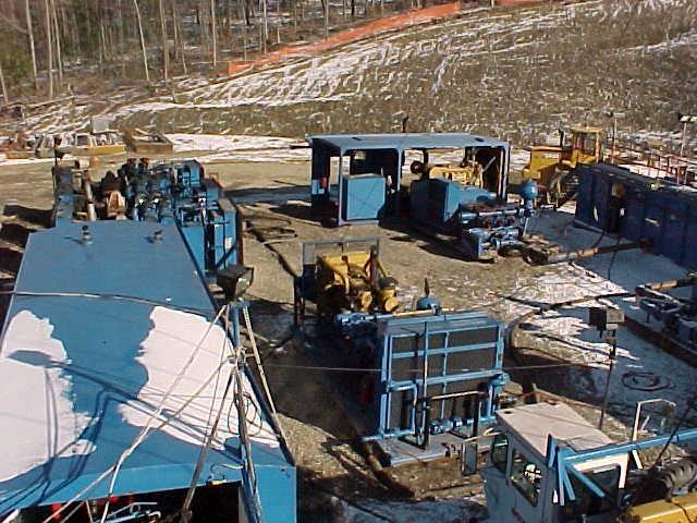
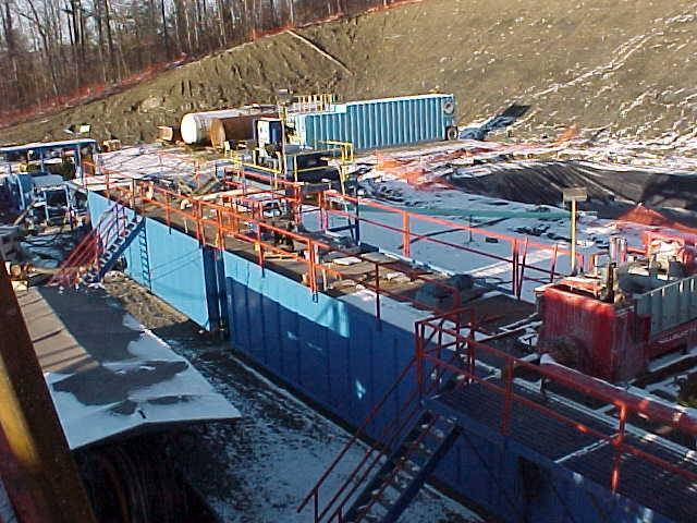
4 Air Drilling Site

5 Why Use Air Drilling? Advantages No Pay Zone Damage Increased Penetration Rate Deviation Control Differential Sticking Reduction Lost Circulation Control Lower Bit Costs Continuous Pay Zone Evaluation Tolerates Formation Fluid Influx Low annular Friction Low Air Volume Requirements
6 Pay Zone Drilling Many gas reservoirs or pay zones experience very low bottom hole formation pressures and gradients, and are marginal producers when drilled based with a fluid based drilling system. The economics of producing these wells becomes greatly hampered when drilled with conventional drilling fluids. The (pay zone) systems supplied by different service companies can be readily adaptable.
7 Pay Zone Hazards The use of air to drill through these pay zones prevents skin damage and overbalancing which are both common with mud. The major advantage is that the sensitive pay zone is not exposed to any fluids. In addition, an inexpensive flow test can be easily conducted without pulling the drill string out of the hole.
8 Applications for Air Drilling Use Low pressure reservoirs Dry, hard formations Wet, hard formations Unconsolidated formations Fractured formations Deviated formations Large diameter holes

9 Air Drilling Unit
10 Advantages of Air for Drilling Used where drilling muds would damage formations. For economics. High penetration rates. Air is used in hard rock formations where there is no, or depleted pressure.
11 Advantages of Air Circulation Air allows under balanced circulation resulting in formation fluid entry to the well bore and eliminating drilling fluid and cutting damage to the formation.
12 Air Drilling Limitations Air drilling is not used: If conventional muds must be used Areas with frequent water zones High pressure zones Unstable formations Most of the time when a rig drills this type of zone the well is lost! Most wells in the Northeast are low/pressure-high/volume. Some of these wells produce up to 70 million cubic/ft of gas.
13 Rental of Surface Equipment Most air and gas drilling equipment is available on a rental basis from contractors that supply various air and gas drilling equipment. The contractors supply the necessary surface equipment to carry out air drilling operation equipment to rotary drilling contractors.
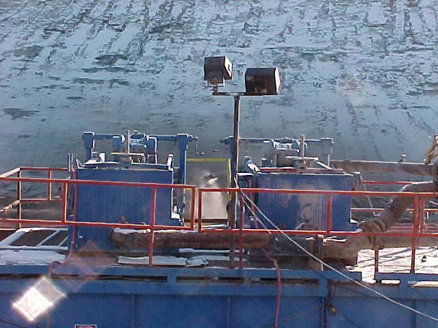
14 Air Compressors
15 Compressors and Boosters Compressors are equipped with after-cooling systems to cool the output flow stream to the acceptable limits (about 150 to 190 F). The number of compressors needed depends on the expected characteristics of the borehole as well as the surface location (i.e., elevation). The necessary manifold piping to connect the compressors and boosters to the rig equipment is supplied by the air and gas drilling equipment contractor. The compressors supply initial air under pressure (100 psi to 300 psi) for drilling or for charging the booster. If additional pressure for drilling is needed, the booster can utilize the compressor s output and increase the line pressure to as much as 1,500 psi.
16 Compressors and Boosters Chemical or Water Tank and Pump The pump injects water, chemical corrosion inhibitors, and liquid foamers into the high pressure air/gas line after initial compression and boost compression of the air/gas. Even in dry air (or dust) drilling, some water and chemical corrosion inhibitors may be injected. In mist drilling, a corrosion inhibitor should be injected with the water. In normal unstable foam drilling, a liquid foamer, which usually has a corrosion inhibitor, is injected.
17 Compressors and Boosters Solids Injector This is used to inject hole-drying powder into the wellbore to dry any water seeping into the borehole from water-bearing formation; it is also used to inject other solids, such as those that reduce torque between the drill string and the borehole. Meter for Measuring Air (or Gas) Volumes A standard orifice plate meter is generally used for measuring air (or gas) injection volumes.

18 Air Compressors (Boosters)
19 Standard Air Equipment 900 CFM-350 psi discharge two stage compressor. Two stage booster. Variable speed/displacement mist pump (35 1,850 psi). Variable speed/displacement chemical Injection pump (10 1,850 psi) 1,000 gallon water storage tank with charger pump.
20 Trailer Mounted Equipment Example Trailer Mounted Unit Components: One Sulliar 900 CFM-350 psi discharge Rotary Screw Two Stage Compressors powered by Detroit Diesel 475 HP 12V. One Joy WB 12 15,000# Rod Load Reciprocating Two Stage Booster Powered by Detroit Diesel 320 HP 8V71. Hydraulic powered Variable Speed/Displacement Positive Reciporcating Tri-Plex Mist Pump capable of 35 gallons per 1,850 psi.
21 Trailer Mounted Equipment Example (cont.) Hydraulic powered Variable Speed/Displacement Positive Reciporcating Tri-Plex Chemical Injection pump capable of 10 gallons per 1,850 psi. 1,000 Gallon Water Storage Tank with Hydraulic Powered Charge Pump.
22 Air/Gas Equipment Suppliers The air/gas equipment supplier usually provides the following: All necessary manifold piping to connect the compressors and booster to the rig equipment. The air scrubber. The chemical tank and pump. The solids injector equipment. Air and gas metering is provided as part of the pipe manifold.
23 Drilling Contractor Supplies The drilling contractor supplies the majority of the drilling equipment. Additionally, contractors typically also provide the following for air operations: Compressors Booster Float valve subs Kelly Rotating head Bleed-off line The sample catcher The bleed-off line Air (or gas) jets The pilot light The gas sniffer The burn pit Blooey line
24 Float Valve Subs Float Valve Subs Run at the bottom and near the top of the drill string. The bottom float valve sub prevents the backflow of cutting into the drill string during connections or other air (or gas) flow shutdowns that would otherwise plug the bit. The bottom float valve sub will also aid in preventing extensive damage to the drill string in the event of a downhole fire.
25 Float Valve Subs The top float valve sub (optional) will aid in retaining high-pressure air within the drill string while making connections. The upper float valve should be released by opening it when it comes out of the hole. This can be done with a sinker bar or a wire line. Pressure may be trapped and caution used when opening the valve. Some operators use ported valves to allow bleeding of pressure during trips.
26 Scrubber This removes excess water from the injected air (or gas) stream to ensure that minimal moisture is circulated (where dry air is required) and to protect the booster.
27 Equipment Differences The BOP stacks are somewhat different than most areas. Air drill rigs use air heads or rotating heads on the top of the stack. This is the only line of protection from a blowout - not a kick.
28 BOP Requirements Below is a typical example of BOP requirements: The 13-5/8 3M annular preventer installed on the 13-3/8 casing (Test pressure 500 psi or maximum discharge pressure of 2-stage air). The 11 5M double ram BOP & 11 5M annular preventer (test pressure 4,000 psi for double ram BOP, 2,000 psi for annular preventer) installed on the 9-5/8 casing. A 5,000 psi kelly valve(s) should be used and tested with the 11 5M BOP stack.
29 BOP Requirements Rotating Kelly Packer: Also called a rotating head or rotating blowout preventer (RBOP). - Packs off the annulus return flow from the rig floor (i.e., seals against the rotating kelly) and diverts the upward flowing air (or gas) and cuttings to the blooey line while allowing pipe rotation and up/down movement. Little pressure (a few psi) exists in the annular flow at the rotating head. - If reverse circulation is utilized, a pressure of several hundred psi is exerted on the rotating head. A hexagonal kelly should be used because the RBOP cannot effectively seal on a square kelly.
30 BOP Requirements All BOP s must be pressure tested to the listed test pressures before the drilling of new hole commences. A test plug is employed for use on the 9-5/8 casing. The BOP s should be function tested as frequently as required by operator. The 13-5/8 3M BOP s are installed prior to drilling out of the 13-3/8 casing shoe. The 11 5M BOP s are installed prior to drilling out of the 9-5/8 casing.

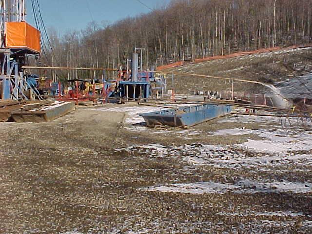
31 BOP Setup on Air Drilling Rig

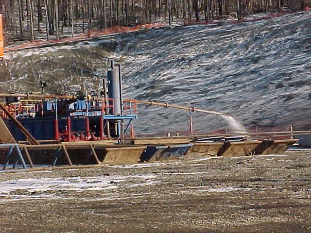
32 BOP Showing RBOP

33 Choke Manifold

34 Choke Manifold

35 Power House for Top Drive
36 Instrumentation In addition to normal rig instrumentation, accurate pressure gauges should be installed in the low and high pressure air (or gas) lines. In particular, a gauge should be installed at the stand pipe and another at the meter run after the compressor (or booster). If possible, both pressure gauges should be provided with 12 or 24 hour pressure recorders.
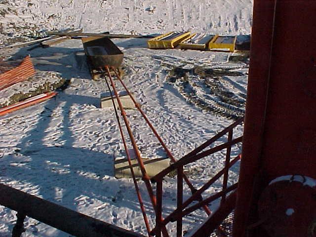
37 Instrumentation The recorder at the meter run is a part of the orifice meter where constant pressure and differential pressure are measured. Measurements at both stations will allow easy calculation of air volume output, which is very important should air pressure decrease or increase during drilling. Also, a high pressure alarm set to indicate any unusual increase in air/gas injection drilling pressure should be installed on the rig floor. These pressure changes are important and helpful in determining problems down hole.
38 Bleed - Off Line The bleed-off line bleeds pressure in the stand pipe, rotary base, and the drill pipe. It allows air or gas in the string assembly to vent pressure directly to the blooey line. The bleed-off line is generally used when making connections and allows rig operators to quickly reduce pressure in the flow lines prior to connections or making trips.
39 Blooey Line This carries exhaust air and cuttings coming from the annulus to the flare pit. The length of the blooey line should be sufficient to keep dust exhaust from the line from interfering with the rig area operations. The length usually used is about 100 ft to 300 ft. The blooey line should not have any curved joints (i.e. L s) and should be tied down to the surface with rigid supports.
40 Blooey Line The end of the blooey line should terminate downwind from the prevailing wind. It is important that the ID of the blooey line be as large as practical. 7 lines are used in many areas. The large ID diameter blooey lines help compensate for the fluid flow energy loss that will occur as the flow of air (or gas) and cuttings make the 90 turn at the preventer from vertical flow to horizontal flow under the rig floor.
41 Drilling With Gas in the Blooey Line As was stated earlier, air drilling operations don t take kicks, they take blowouts on top of the ground. They usually know where the pay zones are with sufficient time to get the crew ready for whatever comes next. The blooey line should be at least 80 feet down wind of the rig.
42 Well Flaring Operations An example of a Flare Line Installation would be: The choke manifold consists of a 4 1/16 5M choke line, 2 ea. 4 1/16 5M valves, 2 ea. 2 1/16 5M valves, 2 ea. 2 5M manual chokes and the necessary 4 casing and 2 tubing lines to the flare pit. The flow line from the wellhead to the flare pit is typically constructed of a 7 line pipe or casing. This flow line should be buried where possible and secured with anchors or tubs if it can not be buried.

43 Well Flaring Operations
44 Sample Catchers A small diameter pipe ( 2 in.) is fixed to the bottom of the blooey line. The small pipe runs into the blooey line at an angle. The end of the sample catcher is held in the blooey line by a structural support welded to the small diameter pipe and the blooey line.
45 Sample Catchers A valve is placed on the small pipe outside the blooey line to facilitate sampling. To sample, the valve is opened and allowed to vent residue material, and a sample of the cuttings is then taken. The sample catcher is placed upstream from the de-duster.
46 Air (or Gas) Jets Jets are often used instead of a bleed off line when large amounts of gas enters the annulus. Switching to the jet allows the reduced air flow from the compressors (and booster) to pass directly to the blooey line. The jets pull a vacuum on the blooey line and therefore on the annulus. Keeps gas from the rig floor area on connections or trips.
47 Pilot Light A small pilot light or flame should be maintained at the end of the blooey line which will ignite any gas while drilling. When drilling with natural gas, the flame should be extinguished until flow is available in the blooey line.
48 Burn Control/Lighting of Flare Line A propane pilot flame should be located at the end of the flowline and kept burning (depending upon the situation). The local fire departments and Emergency Response Centers should be notified when any gas shows are encountered which cause the flare to light.
49 Gas Sniffer A gas sniffer can be hooked into the blooey line to detect very small amounts of gas entering the return flow of air and cuttings from the annulus. The gas sniffer is located on the blooey line just after the return flow from the annulus enters the blooey line.
50 Burn Pit A burn pit should be provided at the end of the blooey line for an air (or gas) drilling operation. The burn pit prevents hydrocarbon liquids from flowing to and burning in the reserve pit and thus prevents a reserve pit fire near the rig. The burn pit location should be away from the standard mud drilling reserve pit.
")
51 Burn Pit (Half Railroad Tank)
52 Burn Pit
53 Stabilizing Tools There are three basic types of stabilizing tools: - Rotating blade stabilizer - Non-rotating rubber sleeve stabilizer - The rolling cutter reamer stabilizer
54 Rotating Blade Stabilizer A rotating blade stabilizer can be a straight blade or spiral blade configuration. In both cases the blades can be short or long. Rotating blades are available in two types: Shop Repairable Rig Repairable
55 Rotating Blade Stabilizer Shop Repairable The shop repairable tools are either integral blade, welded blade or shrunk on sleeve construction. Welded blade stabilizers are popular in soft formations but are not recommended in hard formations because of rapid fatigue damage in the weld area.
56 Rotating Blade Stabilizer Rig Repairable Rig repairable stabilizers either have a replaceable metal sleeve or replaceable metal wear pads. These tools were originally developed for remote locations, but have received widespread acceptance in the last few years.
57 Non - Rotating Sleeve Stablizer The non-rotating rubber sleeve tool is popular stabilizer because it is a safe tool to run from the standpoint of sticking and washover. Very effective in areas of hard formations such as lime and dolomite. Since the sleeve is stationary, it acts like a drill bushing and therefore will not dig into and damage the wall of the hole. The sleeve is made of rubber and temperature over 250 F is not recommended. It has no reaming ability and sleeve life may be short in holes with hard or abrasive formations.
58 Rolling Cutter Reamer Rolling cutter reamers are used for reaming and added stabilization in hard formations. The wall contact area is very small, but it is the only tool that can ream hard rock effectively. Any time rock bit gauge problems are encountered, the lowest contact tool should definitely be a rolling cutter reamer.
59 Bottomhole Assemblies In general, the drill pipe and in particular bottomhole assemblies for air and gas drilling are the same as those used in mud drilling. Because the rate of penetration in air (or gas) drilling is so rapid, special precautions should be taken to prevent hole deviations. Hole deviation problems can be reduced by using less weight on the bit.
60 Bottomhole Assemblies Tri-cone and PDC bits can give high penetration rates, with less weight on the bit. It is established practice to use hammer and hammer bits using a packed hole assembly to try to maintain a straight hole. With air hammer technology advancements of recent years, it is seldom necessary to use stabilization due to the light bit weights required for maximum penetration.

61 Bottomhole Assemblies Hole Deviation This illustration shows that with normal WOB angle increases. By decreasing the WOB the angle drops back to vertical. If the weight is reduced too quickly, a severe dog leg may occur.
62 Bottomhole Assemblies Deviation should be controlled throughout drilling operations. This is very important in the upper part of the borehole. Deviation in this section will create excessive drag and wear on the drill pipe and tool joints as the depth increases. This is especially true when drilling harder formations. These high-transient loads can fatigue the joints and cause premature drill string failure.
63 Bottomhole Assemblies Penetration rates are not highly affected if a stabilization or a pendulum assembly is required with air hammer and hammer bits. However, the use of packed-hole or stiff bottomhole assemblies is recommended. Because of the lack of liquid dampening forces (i.e. water or mud drilling fluid) downhole, the drill string, particularly the bottomhole assembly and the connections between the bottomhole assembly and drill pipe, can be subject to vibration stress.
64 Drilling Methods Pay zone drilling Mist drilling Stable/stiff foam drilling Air (dust) drilling Dusting drilling Aerated fluid drilling Gas (in the blooey line)

65 Air/Mist Drilling Operation

66 Air/Mist Drilling Operation
67 Mist Drilling Mist drilling is used when small amounts of fluid invade the well bore from a wet formation zone. A small amount of foaming/inhibitor agent is mixed with the water and added to the compressed air. Mist drilling maintains high penetration rates while handling the fluid influx. The quantity of fluid entry that can be handled effectively is dependent on the depth and fluid content.
68 Mist Drilling A major condition which governs the success of a mist drilling system is the type of formations exposed. Dry hard,wet hard, fractured, deviated, and low pressure formations are good Mist drilling prospects. Water sensitive shales or sloughing formations are not good mist drilling formations.

69 Mist Drilling
70 Stable/ Stiff Foam Stable/Stiff Foam Drilling is a mixture of fresh/salt water, surfactant, and appropriate chemical additives. It acts like a drilling fluid, cleaning the hole by suspending and carrying the cuttings out of the wellbore. When properly formulated to produce an appropriate liquid volume fraction, stable foam exhibits superior hole cutting carrying capabilities to that of a drilling fluid.
71 Stable/Stiff Foam The lower air volumes needed for a stable foam system results in reduced equipment requirements, particularly in large diameter holes. Also, the lower annular velocities minimizes hole erosion in unconsolidated formations. Stable foam is used in wells with relatively low reservoir pressures. It is exceptional for drilling more than one horizontal hole in the same wellbore, cased hole sand cleanouts, milling cased hole packers, and drilling out cased hole plugs.

72 Stable/Stiff Foam
73 Air (Dust) Drilling Air (dust) drilling is a circulating method providing a high penetration rate. Dry air is compressed and boosted to the required circulation pressure to remove cuttings from the hole with high annular air velocities from 2,500-3,000 feet per minute. Dust drilling is used in medium to hard formation structures, as well as deviated or fractured zones.
74 Dusting
75 Dusting
76 Dusting
77 Aerated Fluid Drilling Aerated fluid drilling refers to a fluid (water or mud) based drilling system into which air is injected into the drill string under pressure in order to lower the hydrostatic pressure in the wellbore often resulting in a desired ECD (Equivalent Circulating Density) of 7 ppg or less. PH values should be kept very high in order to combat the corrosive environment indigenous to an aerated fluid system.
78 Aerated Fluid Drilling Aerated fluid systems are very beneficial in severe loss zones where conventional mud systems cannot function or are cost prohibitive. By regulating air pressure and volumes with the mud pump rate, a state of equilibrium in the annulus is reached, resulting in neither losses or gains to the formation.
79 Maximum Bottomhole Cleaning In air and gas drilling, rock cuttings from the free cutting surface are able to leave the surface rapidly. The bottomhole cleaning effect of the expanding air/gas at the bit nozzles, can be optimized to produce the maximum turbulence at the bit/rock cutting surface. The loose rock stresses of the free cutting surface allow easy rock destruction and initial movement of the cut particles into the flow stream. This is counter to the mud drilling situation where rock destruction by the bit is greatly affected by the fluid hydrostatic pressure at the bottom of the hole.

80 Switching to Mud

81 Yellow U - Pipe
82 Mud Pits

83 Fluid Pumps
84 Mud Pits
85 Shakers

86 Gas Buster

87 Driller s Panel
88 Drill-in Procedure Responsibilities The Rig Manager and Operator s Representative should have a safety meeting with each crew prior to starting their shift to discuss drill-in procedures. They should designate a safe area in which personnel on location will meet should there be an accident or uncontrolled well flow necessitating evacuation of the rig floor.
89 Drill-in Procedure Responsibilities The Rig Manager, Operator s Rep, Mud- logger, or Geologist informs the driller and the rig crew when the penetration of pay zones is anticipated. At this time, the Rig Manager positions the rig crew as follows: Driller at control panel and brake handle. Derrickman at accumulator controls. Chain hand/corner hand positioned to shut down engines if needed
90 Drill-in Procedure Responsibilities All personnel remain in position until instructed otherwise or are relieved. An Operator s Representative or the Mud-logger catches cutting samples. The Operator s Representative and the Rig Manager remain in close proximity to the driller s controls, and maintain checks on all personnel and equipment. The Rig Manager is responsible for teaching all rig personnel their job tasks during an actual shut-in.
91 Drill-in Procedure Responsibilities This will include BOP, choke, and accumulator function and engine shutdown procedures. This training will also include shut-in drills before penetration of any pay zones. Also, hand signals for all shut-in operations are to be mastered by all personnel on location.
92 Before Drill-in Check HCR Valve It is to be in the closed position. Check 4 choke manifold valves The chokes and manifold valves are checked and are open to the gas buster and closed to the earth pit. The chain and corner hands shut down the light plant, then proceed to the safe area.
93 Before Drill-in The Driller and Rig Manager will shut down the rig engines and soap pump engine. The Driller will then proceed to the safe area and the Rig Manager will proceed to the accumulator with the Operator s Representative. If signaled to evacuate the rig floor, Emergency Shutdown Procedures start immediately. The Driller chains down the brake handle before evacuating the rig floor.
94 During Drill-in Large gas flows may be encountered at any depth. There may be a drilling break. If a large gas flow is encountered the rotary table will torque-up or possibly lock-up. The Driller should: Back out torque Kicks out the rotary clutch Picks up the kelly and set the slips high enough on the drill pipe so that the elevators may be latched below the tool joint
95 During Drill-in If the Operator s Representative or Rig Manager confirms that the flow needs to be diverted through the choke manifold; the driller signals the derrickman to open the HCR valve. After the HCR valve is open, the driller signals the derrickman to close the pipe rams. If the kelly cannot be pulled from the BOP due to excessive flow or other reasons, and flow must be diverted through the choke manifold, the driller signals the derrickman to open the HCR valve.

96 Pits and Discharge Line

97 Location View

98 Location View Pipe Rack

99 Choke Manifold Photo
100 A Case History Following is a case history - The slides titled Case History relate to a real life scenario. The slides titled Training evaluate the case history and explore other procedures to support the case history and/or well control operations.
101 Case History Objective To determine if operations handled a kick successfully while air drilling. To determine if other procedures/methods would have accomplished the same results as the method used in the case history. To tie training objectives into case history. Draw conclusions to case history from both operational and training views.
102 Case History Location - Pennsylvania Planned total depth - 9,685 ft Elevation - 1,105 ft Geologic prognosis - 17 formations consisting of: Grey shale, siltstone, limestone, grey & black shale, sandstone, dolomite, gypsum, salt, and red shale.
103 Case History: Casing Program 24 Casing Hole Size: 24 in Depth: 100 ft 20 Casing Cemented back to surface Hole Size: 23 in Depth: 160 ft 13 3 / 8 Casing: 54.5 lb/ft J55 Cemented back to surface Hole size: 17 1 / 2 drilled with Smith H42 hammer bit Depth: 1,000 ft
104 Case History: Drilling Operations After setting 13 3 / 8, began drilling to a target zone of 5,640 ft Casing program called for 9 5 / 8 40 lb J55 casing to be run upon completion Bit 12 3 / 8 Smith H42 hammer bit BHA: NUMA Challenger 125 hammer with 5 / 8 choke 4, 8 OD Drill Collars 4 1 / 2 OD Drill Pipe Mud type: Air/Soap
105 Case History: Drilling Operations Anticipated swapping to air/water based gel (3% KCL, 6 lb/bbl Clay-seal) at 4,000 ft Air requirements: minimum of 4,000 SCFM and 2 Boosters
106 Case History Scenario Company Representative (normally associated with water based drilling) was asked to oversee the air drilling operation. At 3,516 ft, rig encountered extremely high increase in flow at blooey line. Looked to be mostly gas. Operations elected to shut in well.
107 Training: Shut In Procedures for Air Drilling What are the procedures for correctly shutting in an air drilling operation? What are the differences between air and water based shut in procedures? Are there any?
108 Shut in Procedures for Air Drilling Raise drill string out of hole until the kelly clears the rotary table. Shut down compressors and boosters and close kelly safety valve and/or standpipe valve. Close manifold valve(s) from compressors and boosters to standpipe. Close annular preventer.
109 Shut in Procedures for Air Drilling Relieve trapped pressures at surface on manifold/drill pipe. Make sure there is no communication from well on drill pipe side. Determine stabilization point on casing. Read and record shut in pressure. Organize well control operation.
110 Case History: Evaluating the Well Shut in casing pressure on well stabilized at 875 psi. Drill pipe registered a pressure of 160 psi. With multiple float valves in the string, why did drill pipe have pressure on it after bleeding down?
111 Case History: Define the Problem Operations determined that there was a small leak between the connections above the last float valve. Company Man did not think it would create an operational concern when killing the well. Would monitor closely during kill operations.
112 Case History: Solving The Problem Company man elects to estimate bottom hole formation pressure using simple calculations. What formula (s) do you think he used? Why was he interested in determining formation pressure?
113 Case History: Calculations The Company man performed the following calculations: Kick Hydrostatic Pressure: MW ppg x x Feet tvd = Hydrostatic Pressure psi 2 ppg gas x x 3,516 = 366 psi Formation Pressure: SICP + Hydrostatic Pressure = Formation Pressure psi SICP 875 psi psi = 1,241 psi
114 Training: Calculations - Question After determining formation pressure, what calculation did the Company Man use to see if fresh water would kill the well? Fresh Water Hydrostatic Pressure: MW ppg x x Feet tvd = Hydrostatic Pressure psi 8.33 ppg x x 3,516 = 1,523 psi Operations concluded that 1,523 psi of HP would control a formation pressure of approximately 1,241 psi.
115 Training: Solving the Well Control Problem Could the kill weight fluid calculation have been utilized to determine if fresh water would have killed this well? Can shut in casing pressure be used to calculate kill weight mud?
116 Training: Kill Weight Fluid Kill Weight Fluid = SIDPP TVD to bit + Present Mud In air drilling, SICP* can be used instead of SIDPP , = 6.8 ppg Kill Fluid Note: Assumes a 2 ppg gas.
117 Case History: Kill Volume Requirements Fresh water volumes need to be determined to fill drill pipe and annulus. What calculations do you think the Company Man used?
118 Case History: Tbg., Ann. Vol. Requirements Company Man elected to simplify calculations at job site. Drill pipe capacity to MD: Bbls/ft x Ft = Barrels bbls/ft x 3,516 = 50 bbls in Drill String
119 Case History: DP And Ann. Vol. Requirements Annular capacity used to TD: Casing ID: DP OD: 4.5 (OD 2 ID 2 ) = Bbls/ft capacity ( ) = Bbls/ft = bbls/ft Bbls/ft x Ft = volume, bbls bbls/ft x 3,516 = 475 bbls in Annulus Total Volume = 50 bbls bbls = 525 bbls Justification Company Man elects to use casing capacity to TD to ensure extra water volume was on location. The concern was this high volume flow could void water from annulus during well kill operations.
120 Training: Calculations What calculations would you have used to more accurately calculate all tubular and annular volumes?
121 Training: Tubular Volume Requirements DP capacity = bbls/ft; Length 3,396 ft. DC capacity = bbls/ft; Length 120 ft. Bbls/ft x Ft = Barrels bbls/ft x 3,396 = 48.3 bbls in DP bbls/ft x 120 = 0.5 bbls in DC Training Total Barrels in Drill String = 49 bbls. Company Man s calculation = 50 bbls.
122 Training: Annular Volume Requirements Ann. Cap. between Csg and DP = bbls/ft Ann. Cap. between OH and DP = bbls/ft Ann. Cap. between OH and DC = bbls/ft bbls/ft x 1,000 = 135 bbls bbls/ft x 2,396 = 309 bbls bbls/ft x 120 = 10 bbls Training Total barrels in Annulus = 454 bbls Company Man s calculation = 475 bbls
123 Training: Total Volume Requirements Total Barrels in Drill String = 49 bbls Total Barrels in Annulus = 454 bbls Training Total Barrels = 503 bbls Company Man s Total Barrels = 525 bbls On wells where fresh water volumes are critical, these additional calculations may be required. At this point, operations seems to be on track!
124 Training: Additional Volume Requirements Total Barrels in Drill String = 49 bbls Barrels Bit to Casing Shoe = 319 bbls = 368 bbls What is the importance of knowing this volume? (Please take a few minutes to consider this and we will address further into the case history scenario.)
125 Case History: Determining Strokes and/or Time to Kill Well Pump output = bbls/stk Company Man then elects to calculate strokes to fill Drill Pipe: Barrels in DP Pump Output bbls/stk = Strokes to Pump Vol. 50 bbls bbls/stk = 373 strokes Bottoms Up Total Volume to be Pumped: Total Barrels Pump Output bbls/stk = Strokes to Pump Vol. 475 bbls bbls/stk = 3,545 strokes
126 Case History: Kill Procedure Concerns Operations concerned about the high volume they encountered before shutting in well. Were concerned that high flow rates could prevent filling annulus with water on location. Operations elects to kill well through choke rather than through blooey line.
127 Case History: Kill Procedure Operations verifies alignment of all valves. Choke fully opened before operations begin. Company Man begins to fill drill pipe volume with water at high pump rate of 50 stks/min. After 50 bbls are pumped, Company Man elects to close choke back to established shut in casing pressure of 875 psi while continuously pumping. What was the purpose of adding this pressure? How does he reduce this pressure when filling annulus with fresh water?
128 Case History: Kill Procedure Company Man elects at this point to monitor time vs. strokes to complete kill operation (bottoms up) and to reduce casing pressure in relation to gaining hydrostatic pressure with kill fluid (fresh water). Bbls Pump Output bbls/stk = Strokes to pump volume 475 bbls bbls/stk = 3,545 stks to fill annulus Strokes Pump Rate stks/min = Time to pump volume 3,545 stks 50 stks/min = 71 min What was the reason for swapping to minutes?
129 Case History: Kill Procedure Company Man elects to back off pressure on casing side while utilizing time. 875 psi 71 min = 12.3 psi/min Every 8 minutes, Company Man bleeds 100 psi off casing. Was this approximation correct? Elects to hold remaining 75 psi until shutting down operations. Does everyone understand why he did this?
130 Training: Reduction in Casing Pressure There are several ways to calculate and monitor casing pressure reduction when gaining fluid hydrostatic head in the annulus. The Company Man elected to use time to simplify his operations. Does anyone know how to use strokes vs. time?
131 Training: Reduction in Casing Pressure Pressure Strokes (bit to surface) , , , , , , ,195 10? 3,545 (3,550)
132 Training: Reduction in Casing Pressure Does anyone recommend completing a pressure chart with bit to casing shoe volumes being considered? How would this change the beginning of the reduction of 875 psi? By holding 875 psi until kill fluid reaches casing shoe, have we applied any additional stress to the formation at the shoe? We can now answer why the additional calculation (surface to casing shoe volume) is critical in relation to holding casing pressure.
133 Case History Conclusion From the case history above, do you feel that the Company Man was successful in killing the well? Are there any other recommendations or concerns that should have been addressed during this operation? Always remember, there are multiple ways to attack a well control operation!!!
134 Training: Well Control Conclusions Water considerations Killing well at high rate Blooey line vs choke Calculating kill fluid Understanding pressure relations when filling annulus Using kill sheet to assist operations Understanding when to use back pressure to minimize water loss Determining if well is dead Safety meeting before start up
135 Air Drilling Learning Objectives You learned the basics of: Air drilling equipment You also learned how to apply well control principles to air drilling operations. Types of air drilling Differences between mud and air drilling
Air and Gas Drilling
 Air and Gas Drilling Air and Gas Drilling It is a technique in which the more common drilling fluids, (water or mud) are replaced by highly compressible Air or Natural gas. But Compressibility makes pressure
W I L D W E L L C O N T R O L PRESSURE BASICS AND CONCEPTS
 PRESSURE BASICS AND CONCEPTS Pressure Basics and Concepts Learning Objectives You will be familiarized with the following basic pressure concepts: Defining pressure Hydrostatic pressure Pressure gradient
DAY ONE. 2. Referring to the last question, what mud weight would be required to BALANCE normal formation pressure?
 DAY ONE 1. Normal formation pressure gradient is generally assumed to be: A..496 psi/ft B..564 psi/ft C..376 psi/ft D..465 psi/ft 2. Referring to the last question, what mud weight would be required to
IWCF Equipment Sample Questions (Combination of Surface and Subsea Stack)
") IWCF Equipment Sample Questions (Combination of Surface and Subsea Stack) 1. Given the volumes below, how much hydraulic fluid will be required to carry out the following operations (no safety margin)?
IWCF Equipment Sample Questions (Combination of Surface and Subsea Stack) 1. Given the volumes below, how much hydraulic fluid will be required to carry out the following operations (no safety margin)?
IWCF Equipment Sample Questions (Surface Stack)
") IWCF Equipment Sample Questions (Surface Stack) 1. During a well control operation 4000 psi was shut in below the middle pipe rams. Ram type BOP data: Model: Cameron U type Rated Working Pressure: 15000
IWCF Equipment Sample Questions (Surface Stack) 1. During a well control operation 4000 psi was shut in below the middle pipe rams. Ram type BOP data: Model: Cameron U type Rated Working Pressure: 15000
1. The well has been shut in on a kick and the kill operation has not started.
 Well Control Methods Day 2 1. The well has been shut in on a kick and the kill operation has not started. Shut in drill pipe pressure Shut in casing pressure 500 psi 700 psi After stabilization, both pressures
Study Guide IADC WellSharp Driller and Supervisor
 Times to Flow Check: Before pulling out of the hole Before pulling BHA into the BOP When bit is pulled into the casing Increase in cuttings at shakers with same ROP On connections Upon abnormal trip tank
Understanding pressure and pressure
 CHAPTER 1 1-1 PRESSURE BASICS Remember to think downhole. The concepts provided in this section cover the foundations for good well control. Understanding pressure and pressure relationships is important
Dilution-Based Dual Gradient Well Control. Presented at the 2011 IADC Dual Gradient Workshop, 5 May 2011 by Paul Boudreau, Dual Gradient Systems LLC
 Dilution-Based Dual Gradient Well Control Presented at the 2011 IADC Dual Gradient Workshop, 5 May 2011 by Paul Boudreau, Dual Gradient Systems LLC In this very short presentation, we will Review Dilution-based
Rig Math. Page 1.
 Page 1 The Calculator and Main Keyboard Display Numerical 10-key pad used for entering numerical values Trigonometric Functions These keys will be used where wellbore angle is an issue These are the keys
Worked Questions and Answers
 Worked Questions and Answers A Learning Document for prospective Candidates For the Rotary Drilling Well Control Test Programme Copyright, IWCF June 2000 Revision No.1, November 2000 IWCF 2000 page 1 of
WILD WELL CONTROL WARNING SIGNS OF KICKS
 WARNING SIGNS OF KICKS Warning Signs of Kicks Learning Objectives You will learn the warning signs that indicate the well may be kicking: Warning signs of kicks False kick indicators You will also learn
OCEAN DRILLING PROGRAM
 BIH OCEAN DRILLING PROGRAM www.oceandrilling.org Scientifi c Application Packers A packer is an inflatable rubber element that inflates to seal the annular space between the drill string and the borehole
W I L D W E L L C O N T R O L FLUIDS
 FLUIDS Fluids Learning Objectives You will learn about different fluids that can be used in well control. You will become familiar with the characteristics and limitations of fluids. You will learn general
W I L D W E L L C O N T R O L CIRCULATION & WELL CONTROL
 CIRCULATION & WELL CONTROL Learning Objectives You will learn: The importance of pump rates and pressures during well control operations Pressure relationships Basic calculations necessary in well control
August 21, Deepwater MPD / PMCD
 August 21, 2011 Deepwater MPD / PMCD Managed Pressure Drilling (MPD) Pressure held on top of riser while drilling. Drill in overbalance condition Pressurized Mud Cap Drilling (PMCD) Pressure of mud column
Deepwater Horizon Incident Internal Investigation
 Not all Information has been verified or corroborated. Subject to review based on additional information or analysis. Deepwater Horizon Incident Internal Investigation 1 Areas of Discussion Investigation
SUBSEA KILL SHEET EXERCISE No. 5
 Subsea Kill Sheet Exercise No. 5 SUBSEA KILL SHEET EXERCISE No. 5 Name: Date: Complete the Subsea vertical kill sheet provided on pages 2 and 3. Then answer questions 1 to 12. Please round calculations
VOLUMETRIC METHODS and STRIPPING OPERATIONS
 VOLUMETRIC METHODS and STRIPPING OPERATIONS WELL CONTROL SCHOOL Muscat, Oman Training Center VOLUMETRIC METHODS and STRIPPING OPERATIONS The material contained here, is based on the best sources available
W I L D W E L L C O N T R O L SHUT-IN PROCEDURES
 SHUT-IN PROCEDURES Shut-in Procedures Learning Objectives You will learn general shut-in procedures: For surface BOPs. For subsea BOPs. You will learn to interpret shut-in pressures and be able to perform
Blowout during Workover Operation A case study Narration by: Tarsem Singh & Arvind Jain, OISD
 1. Introduction An incident of gas leakage from a well took place during workover operations. Subsequently, the gas caught fire on the fourth day in which twelve persons were injured. Two contract workers,
Chapter 5 HORIZONTAL DRILLING
 Chapter 5 HORIZONTAL DRILLING Chapter 5 How much money am I about to put on the table for a horizontal well? Did I do sufficient planning? Keys to Successful Horizontal Wells Multi-disciplined teams working
Offshore Managed Pressure Drilling Experiences in Asia Pacific. SPE paper
 Offshore Managed Pressure Drilling Experiences in Asia Pacific SPE paper 119875 Authors: Steve Nas, Shaun Toralde, Chad Wuest, SPE, Weatherford Solutions Sdn Bhd, SPE, Weatherford Indonesia SPE, Weatherford
float equipment OPERATING MANUAL TYPE 505/506 Float Equipment 1. INFORMATION & RECOMMENDATIONS Float Equipment
 Contents 1. GENERAL INFORMATION & RECOMMENDATIONS 1 2. INSTALLATION FLOAT EQUIPMENT 2 2.1 PRE-USE FIELD INSPECTION 2 2.2 POSITION FLOAT ON CASING STRING 3 3. RUNNING OF FLOAT EQUIPMENT 3 3.1 CIRCULATION
Casing Design. Casing Design. By Dr. Khaled El-shreef
 Casing Design By Dr. Khaled El-shreef 1 Casing Design CONTENTS Function of Casing Casing Types & Tools Strength Properties Casing Specification Casing Design 2 1 RUNNING AND CEMENTING CASING Reasons for
DB Bridge Plug. Features. Benefits. Applications
 DB Bridge Plug The WELLFIRST Premium Cast Iron Bridge Plug designed to run on electric line. Rated between 2000-10000-psi differential, and 300 F from above and below. Features Field Proven Design Constructed
Practice Exam IADC WellSharp Driller and Supervisor
 Workover & Completion Day 4 1. In a workover operation of a shut in well a Lubricator is being used together with a Wireline BOP / Wireline Valve. Which Barrier is classified as the Primary Barrier? A.
Inflatable Packer Single & Double. Single & Double Packer Dimension. Wireline Packer. Water Testing Packer (WTP) Packer
 Packer") Inflatable Packer Single & Double Single & Double Packer Dimension Wireline Packer Water Testing Packer (WTP) Packer Packer Working Pressure & Depth Chart Packer Water Hand Pump Packer Air Driven Pump
Inflatable Packer Single & Double Single & Double Packer Dimension Wireline Packer Water Testing Packer (WTP) Packer Packer Working Pressure & Depth Chart Packer Water Hand Pump Packer Air Driven Pump
Hard or Soft Shut-in : Which is the Best Approach?
 HARD - SOFT shut-in? Hard or Soft Shut-in : Which is the Best Approach? March '93 INTRODUCTION There is now reasonable acceptance through-out the industry for the use of a hard shut-in procedure following
Drilling Efficiency Utilizing Coriolis Flow Technology
 Session 12: Drilling Efficiency Utilizing Coriolis Flow Technology Clement Cabanayan Emerson Process Management Abstract Continuous, accurate and reliable measurement of drilling fluid volumes and densities
RULES OF THE OIL AND GAS PROGRAM DIVISION OF WATER RESOURCES CHAPTER DRILLING WELLS TABLE OF CONTENTS
 RULES OF THE OIL AND GAS PROGRAM DIVISION OF WATER RESOURCES CHAPTER 0400-52-06 DRILLING WELLS TABLE OF CONTENTS 0400-52-06-.01 Drilling Equipment 0400-52-06-.03 Casingheads 0400-52-06-.02 Blowout Prevention
Float Equipment TYPE 925/926
 Type 925 Float Collar Plunger Valve Float Equipment For less demanding well conditions, such as shallower depths or lower pressures, Top- Co offers economical float equipment certified to API RP 10F category
Model A Sleeve Valve Cement Retainer
 Ret. O.D. Model A Sleeve Valve Cement Retainer DIMENSIONAL DATA A B C D E F G H J K L M N P Q R 3.593 3.593 3.500 2.500 3.531 3.531 1.345 3.375.750.437 2.437 2.187 7.062 2.437 5.312 11.685 20.093 3.937
Type 967 Diamond Broaching Type 968 Sidewinder reamer shoe
 Type 965 float collar Type 966 float shoe 1. GENERAL INFORMATION & RECOMMENDATIONS Type 967 Diamond Broaching Type 968 Sidewinder reamer shoe Type 969 Sidewinder reamer shoe Float Equipment Top-Co Float
MOCS. Multiple Opening Circulation Sub. Fluid Bypass Valve
 MOCS Multiple Opening Circulation Sub Fluid Bypass Valve 1 Applications BHA Protection o o Pumping LCM Spotting Acid Work-over and completions o o o Well bore cleanout Fluid displacements Bottoms-up circulation
W I L D W E L L C O N T R O L COMPLICATIONS
 COMPLICATIONS Complications Learning Objectives You will learn to detect changes that deviate from established trends. You will learn how to respond to problems such as: Pump problems String problems Hole
HydroPull. Extended-Reach Tool. Applications
 Extended-Reach Tool HydroPull This tool incorporates a cycling valve that momentarily interrupts the flow to create water-hammer pressure pulses inside coiled or jointed tubing used in horizontal well
ECD Reduction Tool. R. K. Bansal, Brian Grayson, Jim Stanley Control Pressure Drilling & Testing
 ECD Reduction Tool R. K. Bansal, Brian Grayson, Jim Stanley Control Pressure Drilling & Testing Drilling Engineering Association, Fourth Quarter Meeting November 20, 2008 1 Presentation outline Description
Well Control Drill Guide Example Only. Drill Guide is the list of drills, questions and attributes that are in DrillPad.
 Well Control Drill Guide Example Only Drill Guide is the list of drills, questions and attributes that are in DrillPad. This Well Control Drill Guide will be used in conjunction with the rig-specific well
Bridge Plugs, Ball Drop & Caged Ball Plugs For Zone Isolation
 Bridge Plugs, Ball Drop & Caged Ball Plugs For Zone Isolation ADVANTAGE composite bridge plug, caged ball and ball drop (flow thru) frac plug provide a means to isolate multiple zones during high pressure
North American sealing solutions Bridge Plug Ball Drop Frac Plug Caged Ball Frac Plug
 North American sealing solutions Bridge Plug Ball Drop Frac Plug Caged Ball Frac Plug The North American Sealing Solutions composite bridge plug, caged ball and ball drop (flow thru) frac plug provide
APPENDIX A1 - Drilling and completion work programme
 APPENDIX A1 - Drilling and completion work programme Information about the well and drilling To the extent possible, the international system of units (SI) should be adhered to, and the drilling programme
6-3/4 DUAL PORTED PBL BYPASS SYSTEM (Applicable to sizes 6-1/4 & 6-1/2 also)
") RECEIVING PBL AT RIG SITE TITLE: Operating Instructions for -3/4 PBL -3/4 DUAL PORTED PBL BYPASS SYSTEM (Applicable to sizes -1/4 & -1/2 also) OPERATING INSTRUCTIONS 1. On receipt of PBL Bypass Tools at
RECEIVING PBL AT RIG SITE TITLE: Operating Instructions for -3/4 PBL -3/4 DUAL PORTED PBL BYPASS SYSTEM (Applicable to sizes -1/4 & -1/2 also) OPERATING INSTRUCTIONS 1. On receipt of PBL Bypass Tools at
Hydro-Mech Bridge Plug
 Manual No: 0620000303 Revision: F Approved By: Quality Engineer Date: 2014-9-9 Hydro-Mech Bridge Plug DESCRIPTION: Map Hydro-Mech Bridge Plug is hydraulically actuated and mechanically set. Compact, with
Chapter 4 Key Findings. 4 Key Findings
 Chapter 4 Key Findings 211 4 Key Findings 212 Chapter 4 Key Findings This summarizes the key findings of the investigation team based on its extensive review of available information concerning the Macondo
Wellwork Chronological Regulatory Report
 Well Name: UNIVERSITY 49 #0808H Field: Lin (Wolfcamp) S/T/R: / / County, State: Location Desc: Operator: Enduring Resources, LLC Project Type: Completion District: Southern Project AFE: DV02151 AFE's Associated:
Perforating Options Currently Available in Horizontal Shale Oil and Gas Wells. Kerry Daly, Global BD Manager- DST TCP
 MENAPS 2013 Perforating Options Currently Available in Horizontal Shale Oil and Gas Wells Kerry Daly, Global BD Manager- DST TCP MENAPS 13-17 WELL FLOW MANAGEMENT TM Scope/ Contents: MENAPS 13-17 Study
Restoring Fluid Flow in Tubing Strings
 Restoring Fluid Flow in Tubing Strings Andrew Roth, Product Manager Fike Corporation Fike Hydraulic Tubing Drains (HTD) for use with deep hole drilling tools, downhole devices and other oil and off shore
International Well Control Forum. IWCF Drilling Well Control Syllabus Level 3 and 4 March 2017 Version 7.0
 International Well Control Forum IWCF Drilling Well Control Syllabus and 4 March 2017 Version 7.0 IWCF Drilling Well Control Syllabus and 4 Contents Guidance Notes... 5 1.1. Introduction... 5 1.2. Who
BLOCK: CB-ONN-2010/8 GUJRAT-INDIA
 Well Control Manual Bharat PetroResources Limited BLOCK: CB-ONN-2010/8 GUJRAT-INDIA Prepared By: EnQuest PetroSloutions Pvt. Ltd. Contents 1.0.0 Definitions 2.0.0. Causes of Kicks 3.0.0. Kick indications
Faculty of Science and Technology. Master Thesis. Writer: Audun Tufte Veisene (Writer s signatures)
") Faculty of Science and Technology Master Thesis Study program/ Specialization: Petroleum Engineering/ Drilling Technology Spring semester, 2014 Open Writer: Audun Tufte Veisene (Writer s signatures) Faculty
Faculty of Science and Technology Master Thesis Study program/ Specialization: Petroleum Engineering/ Drilling Technology Spring semester, 2014 Open Writer: Audun Tufte Veisene (Writer s signatures) Faculty
Coiled Tubing string Fatigue Management in High Pressure Milling Operation- Case Study
 Coiled Tubing string Fatigue Management in High Pressure Milling Operation- Case Study Abstract: Paper Presenter: Ebrahim Rabbani 1 e.rabbani@mehranservices.com Ebrahim Rabbani, Danial Davoodi 2, Fatemeh
INTERPRETATION NOTE ISSUED UNDER THE PETROLEUM DRILLING REGULATIONS (CNR 1150/96)
") BOP CLASSIFICATION SYSTEM FOR ONSHORE NEWFOUNDLAND AND LABRADOR INTERPRETATION NOTE ISSUED UNDER THE PETROLEUM DRILLING REGULATIONS (CNR 1150/96) PREPARED BY THE PETROLEUM RESOURCE DEVELOPMENT DIVISION
BOP CLASSIFICATION SYSTEM FOR ONSHORE NEWFOUNDLAND AND LABRADOR INTERPRETATION NOTE ISSUED UNDER THE PETROLEUM DRILLING REGULATIONS (CNR 1150/96) PREPARED BY THE PETROLEUM RESOURCE DEVELOPMENT DIVISION
Irrigation System Winterization and Pressurization Procedures
 Irrigation System Winterization and Pressurization Procedures Introduction Any time that an irrigation system is filled and pressurized, or when the system is drained and water flushed from the system,
SCORPION HIGH-QUALITY, FULLY COMPOSITE PLUGS
 SCORPION HIGH-QUALITY, FULLY COMPOSITE PLUGS A DIFFERENT KIND OF ENERGY COMPANY Nine Energy Service isn t your typical oilfield services company. Our success stems from a culture driven by performance
PowerDrive X6. Rotary Steerable System for high-performance drilling and accurate wellbore placement
 Rotary Steerable System for high-performance drilling and accurate wellbore placement The PowerDrive X6 RSS maintains control under the most difficult conditions, bringing the benefits of rotary steerable
Injection Systems INSTALLATION AND OPERATING GUIDE HI FLO VERTICAL TANK SYSTEMS
 TM INSTALLATION AND OPERATING GUIDE HI FLO VERTICAL TANK SYSTEMS When the HI-FLO Metering Head is attached to a tank, the tank will be pressurized to the same pressure as the irrigation system. Before
Subsea Safety Systems
 Subsea Safety Systems The ELSA-HP has been developed to service the high pressure horizontal tree completion and intervention market. With systems designed and qualified up to 15,000 psi, 250 degf and
Drilling Morning Report
 REPORT DATE 5/0/200 Report # AFE # Casing OD(in) WT(lbs/ft) Grade Btm MD(ft) Btm TVD(ft) DCRB04 TVD: 32 MD: 32 Progress: 32 Planned TD:,500 Current Hole Size: Days From Spud: Spud Date: 5//0 Days on Well:
Air Operated Hydraulic Pumping Systems to 50,000 psi
 High Pressure Equipment Air Operated Hydraulic Pumping Systems to 50,000 psi PS-10: 10,000 psi PS-20: 20,000 psi PS-30: 30,000 psi PS-40: 40,000 psi PS-50: 50,000 psi PS-90: 90,000 psi High Pressure air
"Sharing To Be Better. Influx through failed cement in shoetrack during completion operations
 "Sharing To Be Better Influx through failed cement in shoetrack during completion operations 2 Well status completion operations Seabed @ 364m 7" liner cemented across reservoir Well filled with 1.54 SG
Solid Expandable Tubular Technology: The Value of Planned Installation vs. Contingency
 Solid Expandable Tubular Technology: The Value of Planned Installation vs. Contingency Chris Carstens Unocal Corporation 14141 Southwest Freeway Sugar Land, Texas 77478 Mike Breaux Unocal Corporation 14141
NEW PROGRAM! OIL AND GAS TECHNOLOGY PROGRAM
 NEW PROGRAM! PROGRAM Mechanical Maintenance MODEL H-IRT-1 Industrial Refrigeration Trainer MODEL H-RIG-1C Rigging Systems Trainer MODEL H-IMTS-1 Industrial Maintenance Training System MODEL H-FP-223-14
Why Do Not Disturb Is a Safety Message for Well Integrity
 Why Do Not Disturb Is a Safety Message for Well Integrity Presented at the Practical Well Integrity Conference 9-10 December, 2014 in Houston By Ron Sweatman, Principal Advisor, Reservoir Development Services,
WELL SCAVENGER. Versatile wellbore clean-up tool for the most demanding operations
 WELL SCAVENGER Versatile wellbore clean-up tool for the most demanding operations WELL SCAVENGER: A versatile wellbore cleanup tool for flowrestricted applications The inability to recover wellbore debris
TECHNICAL BENEFITS OF CJS / RAISE HSP. Technical Advantages
 TECHNICAL BENEFITS OF CJS / RAISE HSP Technical Advantages The HSP is designed for low- to mid- volume applications at flow rates of 1 cubic meter to 30 c. m per day. The benefits are in the details. The
R.K. Bansal, Weatherford; P.A. Bern, BP Exploration; Rick Todd, Weatherford; R.V. Baker, BP America; Tom Bailey, Weatherford
 AADE-07-NTCE-69 A Downhole Tool for Reducing ECD R.K. Bansal, Weatherford; P.A. Bern, BP Exploration; Rick Todd, Weatherford; R.V. Baker, BP America; Tom Bailey, Weatherford Copyright 2007, AADE This paper
Extended leak off testing
 Extended leak off testing Rev: 1.0 03/01/01 Purpose To ensure minimal operational time and risk exposure to personnel, process, production and equipment. The following extended leak off test procedures
HOT OILING OPERATIONS ALL HSE PRC 172. Approved By: Manager, HSE Performance Assurance. Table of Contents
 Owner: HSE Performance Assurance ALL HSE PRC 172 Approved By: Manager, HSE Performance Assurance Retention Code: CG01 CA Revised: March 2015 Review Frequency: Five years or less Table of Contents 1.0 Purpose...
WellCAP IADC WELL CONTROL ACCREDITATION PROGRAM
 WellCAP IADC WELL CONTROL ACCREDITATION PROGRAM WELL SERVICING OPERATIONS (WIRELINE, COILED TUBING & SNUBBING) CORE CURRICULUM AND RELATED FORM WCT-2WSI INTRODUCTORY LEVEL For information on how an course
2-7/8 TRIPLE PORTED PBL BYPASS SYSTEM
 RECEIVING PBL AT RIG SITE TITLE: Operating Instructions for 2-7/8 Triple Port PBL 1-10-201 2-7/8 TRIPLE PORTED PBL BYPASS SYSTEM OPERATING INSTRUCTIONS 1. On receipt of PBL Bypass Tools at Rig site, the
RIH intermediate section casing in Bazian-1 exploration oil well
 Energy and Sustainability V 559 RIH intermediate section casing in Bazian-1 exploration oil well A. K. Darwesh Petroleum Engineering Department, Engineering Faculty, Koya University, Kurdistan Abstract
COMPARING PLUG & SEAT REGULATORS & CONTROL VALVES. Lamar Jones. Equipment Controls Company 4555 South Berkeley Lake Road Norcross, GA 30071
 COMPARING PLUG & SEAT REGULATORS & CONTROL VALVES Lamar Jones Equipment Controls Company 4555 South Berkeley Lake Road Norcross, GA 30071 INTRODUCTION The purpose of this paper will be to compare a plug
VRS Assembly & Operating Instructions
 VRS Assembly & Operating Instructions Models VRS-18 Pn #270003 VRS-24 Pn #270006 VRS-30 Pn #270010 Not for use on pressure vessels equipped with Automatic exhaust valve (680 controls) EMPIRE ABRASIVE EQUIPMENT
TECHNICAL DATA. than the water inlet pressure to the concentrate
 Foam102a 1. DESCRIPTION The Viking Low Flow Foam/Water proportioning system, is a UL Listed and FM Approved system, for use with 3M foam concentrates. This system consists of a standard wet pipe sprinkler
Engineered solutions for complex pressure situations
 SPECIAL SERVICES Engineered solutions for complex pressure situations Cudd Energy Services (CES) delivers custom engineered solutions to resolve complex pressure situations resulting from equipment failure
Components for air preparation and pressure adjustment. OUT port position ( ) connected Rear side. of IN port. Air tank. directly.
 connected Rear side. of IN port. Air tank. directly.") Components preparation and pressure adjustment ABP Overview ABP is a component that enables boosting by s only up to twice primary pressure (.0MPa max.) in combination with using air tank but not using
Components preparation and pressure adjustment ABP Overview ABP is a component that enables boosting by s only up to twice primary pressure (.0MPa max.) in combination with using air tank but not using
A New and Simplified Method for Determination of Conductor Surface Casing Setting Depths in Shallow Marine Sediments (SMS)
") AADE-07-NTCE-41 A New and Simplified Method for Determination of Conductor Surface Casing Setting Depths in Shallow Marine Sediments (SMS) Paknejad, A., Texas A&M University; Schubert, J., Texas A&M University
AADE-07-NTCE-41 A New and Simplified Method for Determination of Conductor Surface Casing Setting Depths in Shallow Marine Sediments (SMS) Paknejad, A., Texas A&M University; Schubert, J., Texas A&M University
D & V Oil Co. LP. Daily Completion Report - University CN A #6 API # /23/2016. Perfs ' ' Activity :
 Daily Completion Report - University CN A #6 API # 42-105-42334 12/23/2016 Activity at Report Time: Perfs - 2512' - 2632' Depth at Report Time Put Well on Production 2655' - PBTD Activity : Arrive Location.
Squeeze Cementing. Brett W. Williams Cementing Technical Advisor January 2016 Tulsa API Meeting
 Squeeze Cementing Brett W. Williams Cementing Technical Advisor January 2016 Tulsa API Meeting Definition Squeeze Cementing is the process of applying hydraulic pressure to force or squeeze a cement slurry
On-Off Connector Skirt
 On-Off Connector Skirt Retrievable Packers & Accessories The On-Off Connector Skirt is compact, reliable, fully sealing, J-type tubing disconnect device that automatically engages and releases with a small
WellCAP IADC WELL CONTROL ACCREDITATION PROGRAM
 WellCAP IADC WELL CONTROL ACCREDITATION PROGRAM DRILLING OPERATIONS CORE CURRICULUM AND RELATED JOB SKILLS FORM WCT-02DS SUPERVISORY LEVEL The purpose of the core curriculum is to identify a body of knowledge
OPTIMUM SELECTION OF WELL CONTROL METHODS
 OPTIMUM SELECTION OF WELL CONTROL METHODS Md AHAMMAD SHARIF Assistant professor, Department of Petroleum Engineering, GIET College of Engineering, Rajahmundry. Dr. S. SRIGOWRI REDDY Professor, GIET College
RPSEA UDW Forum June 22 & 23, Secure Energy for America
 RPSEA UDW Forum June 22 & 23, 2010 Secure Energy for America PROJECT TEAM RPSEA Operator Advisory Committee Anadarko Chevron Shell ConocoPhillips Subcontractors IntecSea NOV CTES General Marine Contractors
BANDAR PANJI-1 WELL CONTROL INCIDENT REPORT
 BANDAR PANJI-1 WELL CONTROL INCIDENT REPORT EXECUTIVE SUMMARY I was requested by management to review the Banjar Panji-1 drilling operations from the conception of the Integrated Drilling Management approach
Inflatable Packers for Grouting 11/10/00
 Introduction Inflatable Packers for Grouting 11/10/00 Inflatable packers are frequently used for grout injection in geotechnical applications for structural reinforcement and/or water-proofing of foundations,
DRILLING HOSE SOLUTIONS
 DRILLING HOSE SOLUTIONS HIGH PRESSURE FLEXIBLE LINES FOR A WIDE RANGE OF DRILLING APPLICATIONS HIGH QUALITY - HIGH STANDARD WE DELIVER ACCORDING TO THE HIGHEST LEVELS OF SPECIFICATIONS AND STANDARDS WITH
BLACK HILLS PLATEAU PRODUCTION COMPANY
 BLACK HILLS PLATEAU PRODUCTION COMPANY DRILLING PROGRAM Homer Deep Unit 9 11CH SHL: 300 FNL, 200 FWL, NWNW Sect. 9 T8S R98W BHL: 1350 FSL, 2100 FEL NWSE Sect. 15 T8S R98W Garfield & Mesa Counties, Colorado
SPE/IADC Abstract
 SPE/IADC 125311 Pressurized Mud Cap Drilling Drastically Reduces Non-Productive Time in Soka Field, South Sumatera Michael Runtuwene, Sanny Suprihono, and Dany Rizka, SPE, Medco E&P Indonesia, Andi Eka
New generation of solid expandable liners help give operators a jump on trouble zones
 New generation of solid expandable liners help give operators a jump on trouble zones By Pat York, Weatherford SINCE SOLID EXPANDABLE technology has gained credibility as an effective contingency option,
Texas Administrative Code
 TITLE 16 PART 1 CHAPTER 3 RULE 3.13 Texas Administrative Code ECONOMIC REGULATION RAILROAD COMMISSION OF TEXAS OIL AND GAS DIVISION Casing, Cementing, Drilling, Well Control, and Completion Requirements
Advanced Applications of Wireline Cased-Hole Formation Testers. Adriaan Gisolf, Vladislav Achourov, Mario Ardila, Schlumberger
 Advanced Applications of Wireline Cased-Hole Formation Testers Adriaan Gisolf, Vladislav Achourov, Mario Ardila, Schlumberger Agenda Introduction to Cased Hole Formation tester Tool specifications Applications
OPERATING MANUAL DOUBLE ACTING DRILLING INTENSIFIER HYDRAULIC TYPE
 Page 1 of 8 OPERATING MANUAL DOUBLE ACTING DRILLING INTENSIFIER HYDRAULIC TYPE Size Series 6.50" 478 Reviewed And Approved By: Signature: Initials: Date: Page 2 of 8 Section OPERATING MANUAL DOUBLE ACTING
Step-Rate Formation Integrity Test Method for Geothermal Wells
 GRC Transactions, Vol. 41, 2017 Step-Rate Formation Integrity Test Method for Geothermal Wells William M. Rickard, Ozgur Balamir and Ernesto Rivas Geothermal Resource Group, Inc. services@geothermalresourcegroup.com
The Discussion of this exercise covers the following points:
 Exercise 5-3 Wet Reference Leg EXERCISE OBJECTIVE Learn to measure the level in a vessel using a wet reference leg. DISCUSSION OUTLINE The Discussion of this exercise covers the following points: Measuring
Along-string pressure, temperature measurements hold revolutionary promise for downhole management
 Along-string pressure, temperature measurements hold revolutionary promise for downhole management IT S WIDELY KNOWN that the majority of stuck pipe incidents occur while pulling out of hole. If we can
FUNDAMENTALS OF PRESSURE REGULATORS ROBERT BENNETT MANAGER OF TRAINING ELSTER AMERICAN METER
 FUNDAMENTALS OF PRESSURE REGULATORS ROBERT BENNETT MANAGER OF TRAINING ELSTER AMERICAN METER SUPPLY = DEMAND FUNCTION OF A REGULATOR A regulator may be defined as a "mechanism for controlling or governing
Optimising Hydraulic Energy to Dramatically Improve Lateral Reach
 Optimising Hydraulic Energy to Dramatically Improve Lateral Reach What Affects Reach? Build angle Size of completion CT size Drag Mechanical Fluid Debris in well BHA size End load CT size End load Buoyancy
TAM Single SeT inflatable
 TAM Single SeT inflatable ReTRievAble PAckeRS Sets with pressure only Releases with straight pull or rotate Ideal for horizontal applications Sets in casing or open hole Runs on tubing, coiled tubing,
FREQUENTLY ASKED QUESTIONS
 What are some applications in which you ve successfully used this product? New Completions - Stage by Stage Diversion Between Frac plugs for Intra-Stage Diversion Replace Frac Plugs with Perf PODs - Full