Installation and User Guide
|
|
|
- Jordan Ward
- 5 years ago
- Views:
Transcription


1 INSTANT I3VS MANUAL ELECTRIC HANDWASH Installation and User Guide IMPORTANT: This booklet should be left with the user after installation and demonstration.
2 THIS APPLIANCE CAN BE USED BY CHILDREN AGED FROM 8 YEARS AND ABOVE AND PERSONS WITH REDUCED PHYSICAL, SENSORY OR MENTAL CAPABILITIES, OR LACK OF EXPERIENCE AND KNOWLEDGE IF THEY HAVE BEEN GIVEN SUPERVISION OR INSTRUCTION CONCERNING USE OF THE APPLIANCE IN A SAFE WAY AND UNDERSTAND THE HAZARDS INVOLVED. CHILDREN SHALL NOT PLAY WITH THE APPLIANCE. CLEANING AND USER MAINTENANCE SHALL NOT BE MADE BY CHILDREN DO NOT SWITCH THE APPLIANCE ON IF YOU SUSPECT THE APPLIANCE OF BEING FROZEN. WAIT UNTIL YOU ARE SURE IT HAS THAWED OUT. Your handwash unit has been designed for convenience, economy and safety of use, provided that it is installed, used and maintained in good working order and in accordance with our instructions and recommendations. ALL WIRING AND INSTALLATION MUST BE SUPERVISED BY A SUITABLY QUALIFIED PERSON. THIS APPLIANCE MUST BE EARTHED. The installation must be in accordance with the current edition of BS.7671 (the IET Wiring Regulations ) and Part P of the Building Regulations in force at the time of installation. Installations outside England and Wales must also conform to any local regulations in effect This appliance is intended to be permanently connected to the fixed electrical wiring of the mains supply with its own dedicated supply. This appliance must NOT be fitted where it may be subjected to freezing conditions. Isolate the mains electrical and water supply before removing the appliance front cover. DO NOT fit any sort of tap or control on the appliance outlet. Take care to avoid restricting the outlet of the pressure relief device (fig.c). If water is discharged from the pressure relief device, maintenance will be required before the appliance can be safely used. 2 The following points will help you have a greater understanding of how your handwash works: The electric heating element operates at a constant rate. The required water temperature is achieved by adjusting the rate of water flow. The higher the water flow the lower the temperature and vice versa. The temperature of the water supplied from the mains can vary considerably throughout the year from 5 to 20 C. This means that in the winter, flow rate will be less than in the summer to achieve the same outlet temperature. Your handwash is designed to work within a range of water pressures, if the pressure falls below the minimum pressure required, it is likely that the pressure switch will turn off the power to the heating element, resulting in cold water being produced by the unit. (see page 3 for details)
 We recommend that a WRAS (Water Regulations Advisory Scheme) listed isolating valve is fitted into the mains cold water supply for servicing purposes.")
3 Plan your own installation carefully. Check on the nearest and most readily accessible rising mains water supply. The unit should be sited so that all the spray is contained in the sink (fig.a) We recommend that a WRAS (Water Regulations Advisory Scheme) listed isolating valve is fitted into the mains cold water supply for servicing purposes. ALL WIRING AND INSTALLATION MUST BE SUPERVISED BY A SUITABLY QUALIFIED PERSON. DO NOT INSTALL THIS UNIT WHERE IT MAY BE SUBJECTED TO FREEZING CONDITIONS. USE ONLY THE COLD RISING WATER MAIN SUPPLY. DO NOT CONNECT THE HANDWASH UNIT TO THE DOWN SERVICE FROM A COLD WATER STORAGE TANK. Plumbing the handwash unit must precede making electrical connections. The handwash unit must be connected to the cold water supply with a minimum running pressure of 69 kpa (0.7 bar, 10 psi) and a maximum pressure of 690 kpa (7.0 bar, 100 psi). Turn off the water supply at the isolating tap. Before removing the front cover, check that the control knob is set to off - 12 o clock fully clockwise Remove the three screws securing the handwash unit cover and remove the cover complete with the control knob. 2. Place the handwash unit on the wall and determine the entry position of the water inlet supply pipe. Ø15mm copper, chrome polished or stainless steel pipe should be used. Ensure that there are no burrs on the pipe. In multiple handwash installations, correct pipe work sizes should be calculated to maintain adequate flow to each unit. 3. Mark the location of the fixing screws through the backplate (fig.b). A keyhole slot provided on the top fixing hole to assist installation, and should be marked and drilled first to take the wall plugs and screws provided. 4. Tighten the top screw with head protruding about 10mm from the wall and hook the backplate over the screw head. This allows for correct and accurate alignment of the handwash unit before fixing the bottom position. You may not wish to tighten up both screws at this stage as the holes are elongated to allow for adjustment after other connections have been made 5. Before completing the connection of the water supply to the inlet of the unit, ensure you flush out the pipework to remove all swarf and system debris. 6. Connect the mains water supply to the inlet of the handwash unit using the relevant Ø15mm pipe. Do not use excessive force when making the connection to the unit. We recommend you support the outlet with a spanner (fig.d) 7. It is permissible to use a WRAS (Water Regulations Advisory Scheme) approved sealant sparingly whilst avoiding excess finding its way into the handwash operating parts. TAKE CARE TO AVOID RESTRICTING THE OUTLET OF THE PRESSURE RELIEF DEVICE.

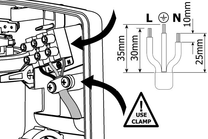
4 THIS HANDWASH MUST BE EARTHED. A The electrical installation must be in accordance with the current BS.7671 (IET Wiring Regulations) and Part P of the Building Regulations and/or local regulations 1. The handwash unit is designed for a single phase AC electrical supply. 2. Use 3-Core 1.5mm² double insulated cable. The cable can be surface clipped, hidden or via conduit. 2. The incoming cable access to the handwash unit must be via the two bottom, the top, or rear channels provided in the backplate (fig.c) 3. Cut back cable (fig.e). Connect cable to terminal block making sure that all the retaining screws are VERY TIGHT and that no cable insulation is trapped under the screws. B 4. Ensure the cable clamp is used to secure the cable into position. FAILURE TO COMPLY WITH THESE INSTRUCTIONS COULD RESULT IN FAILURE OF THE TERMINAL BLOCK IMPORTANT: Fitting the swivel arm must precede fitting the front cover 1. Ensure the rubber O -ring is located fully on the stainless steel pipe. 2. Slide the plastic retainer over the teeth of the outlet until they click into position (fig.f). C 4


5 D F E G H 5
. 3.")
6 It is necessary to engage the control knob in the correct position on the flow valve spindle before the front cover is located. 1. Ensure the 2 x backplate fixing screws are fully tightened (fig.b). 2. Before replacing the front cover, check that the flow valve spindle and the control knob are rotated fully clockwise (fig.g). 3. Refit the front cover with the 3 x fixing screws DO NOT switch on the power to the handwash unit until the commissioning procedure has been carried out. IMPORTANT: Turn the control knob fully anti-clockwise until the valve is fully open. This will ensure a fast fill up of the handwash. Let the water flow through the handwash unit to release any air which may be in the system and fill the handwash with water. IMPORTANT: When a steady water flow is evident, turn the control knob fully clockwise to the off position. 4. Check that the water flows freely from the handwash within a few seconds. The water from the patented Vortex sprayhead will be at full force and at a cool temperature. 5. Rotate the control knob slowly clockwise. This will gradually reduce the water flow with the water temperature remaining cool. 6. Rotate the control knob fully anti-clockwise to return to maximum water flow. 7. Switch on the mains electrical supply at the isolating switch. The Power neon indicator will illuminate. 8. Turn the control knob clockwise and check that the water gets warmer, Turn anti-clockwise and check the water gets cooler. Wait a few moments for the temperature of the water to stabilise. NOTE: When the water temperature is changed the flow rate alters. 9. Turn the control knob fully clockwise to stop the water flow. IMPORTANT: The handwash unit must be full of water before the power is switched on. 1. Make sure that the electrical supply has been isolated at the isolating switch. 2. Ensure the water supply is fully on at the mains and the isolating service valve (if fitted) is fully open, check that water is not leaking from the bottom of the case. 3. Turn the control knob anti-clockwise to the full cold position. 1. The mains electricity and water supply should normally be left on. The flow of the water is controlled by a tap, which is incorporated inside the unit. 2. Turn the knob anti-clockwise 180 (fig.h). This will, in the majority of cases, provide a suitable temperature for washing hands. However, in extreme conditions, i.e. mid-winter or mid-summer, the temperature of the water can be adjusted to suit. 3a. If the water is too hot, then increase the water flow by, Turning the control knob anti-clockwise Wait a few moments for the temperature of the water to stabilise (fig.h). Repeat turning anti-clockwise if necessary until you get the water temperature of your liking. 6


7 3b. If the water is too cold, then decrease the water flow by, Turning the control knob clockwise, and continue as necessary until you get the water temperature of your liking (fig.h). The final adjustment may be anywhere on the scale. 3c. Basically turning the control knob clockwise increases water temperature anti-clockwise decreases the temperature Wait a few moments for the temperature of the water to stabilise. 4. The neon indicator on the front of the handwash shows when the heating element is working. 5. When you have finished handwashing, turn the control knob fully clockwise to the off position. 6. DEMONSTRATE OPERATION TO USERS, AND LEAVE THIS BOOK WITH THEM FOR FUTURE REFERENCE. DO NOT SWITCH THE UNIT ON IF YOU SUSPECT IT OF BEING FROZEN. WAIT UNTIL YOU ARE SURE IT HAS THAWED OUT. CONSIDERATION SHOULD BE GIVEN TO SUPERVISING THE YOUNG, ELDERLY AND THE INFIRM WHILST THEY USE THIS UNIT. Manufacturer Redring Product I3VS Load Profile 3XS Efficiency Class A Efficiency % 37 Consumption (kwh / annum) 205 Sound (db) 15 Precautions Ensure all product care, installation and maintenance instructions listed here are followed 7 BEFORE ANY CLEANING, SWITCH OFF AT THE ISOLATING SWITCH. CLEANING AND MAINTENANCE SHALL NOT BE MADE BY CHILDREN It is recommend that the handwash unit be cleaned using a soft cloth and that the use of abrasive or solvent cleaning fluid be avoided. The patented Vortex spray head does not require de-scaling. We offer a technical advisory service on the telephone to installers and other customers with problems in the field. Please call our technical team on: Or alternatively us on: service.request@redringxpelair.com Remember to quote the exact type of handwash, as written on the front of the unit and on this leaflet. The model and serial number are located on the bottom face of the handwash. Make a note of those numbers here, and be sure to quote them if you call for advice. Model Number: Serial Number: NOTE: You may be charged for a service call if you do not have the serial number.

8 GUARANTEE Terms and Conditions for UK (outside UK contact your local distributor) In the unlikely event of a product breakdown during the guarantee period, you should contact our Service and Repair Helpline who will be able to assist with the repair and advise of the best course of action to be taken. Please DO NOT remove the product prior to making this call as this may invalidate your guarantee. Service and Repair Tel: or technical.services@redringxpelair.com We guarantee this product for a period of 12 months from the date of purchase. Within the guarantee period we will resolve, free of charge, any manufacturing defects in the product resulting from faulty workmanship or material on condition that:- a) The product has been correctly installed and commissioned in accordance with our instructions and is being used on the supply circuit or voltage printed on the rating plate. b) The product has been used in accordance with these instructions and has not been tampered with or otherwise subject to misuse, neglect or accident. c) The product has not been taken apart, modified or repaired except by a person authorised by us. d) Evidence of the date of purchase in the form of an invoice or receipt will be required in order to qualify under the terms of this guarantee. e) For the service work to be undertaken free of charge, the work must only be undertaken by Redring Xpelair Group Limited, or our approved agents. f) Service under guarantee has no effect on the expiry date. The guarantee on any exchanged parts or product ends when the original guarantee period ends. EXCLUSIONS This guarantee DOES NOT cover damage or defects arising from poor or incorrect installation, improper use or lack of maintenance, including the build-up of limescale. It is the responsibility of the installer to check that the installation parameters meet the requirements of the products, and any relevant regulations. If we are called out to a fault, which is subsequently identified as being an installation fault, we will make a charge. It is important that the routine checks are completed before calling us out, as many issues can be simply diagnosed and resolved. A charge will be made where a call under the terms of the guarantee has been booked and a failure was not product related, or an engineer arrives and is not able to gain access. We make no guarantees as to response time for repairs. We will endeavour to achieve the most timely response possible but while we indicate an average response time, this should not be taken as a guarantee. The guarantee applies to a repair or replacement (at our discretion) of the product subject to the conditions above, and DOES NOT cover compensation for the loss of the product or consequential loss of any kind. This guarantee does not apply to the repair or replacement of pressure relief devices, sprayheads, isolating switches, electrical cable, fuses and/or circuit breakers. This guarantee does not affect your statutory rights. Newcombe House, Newcombe Way, Orton Southgate, Peterborough, PE2 6SE Tel: +44 (0) Fax: +44 (0) Technical Service Tel: +44 (0) Technical Service Service.request@redringxpelair.com 8 (A4 Leaflet: a)
SMV-001 Thermostatic Shower Mixer Valve Installation Instructions & Adjustment Settings
 SMV-001 Thermostatic Shower Mixer Valve Installation Instructions & Adjustment Settings 38 READ ALL INSTRUCTIONS CAREFULLY BEFORE INSTALLATION. LEAVE THIS BOOKLET WITH THE END USER FOR FUTURE REFERENCE
TEMPERATURE STABILISED THERMOSTATIC SHOWER PANEL
 Product Support Guarantee This product is guaranteed against faulty materials and workmanship for 12 months from date of purchase. For the guarantee to be valid, the unit must be installed by a competent
bathrooms.com Concentric Thermostatic Shower Mixers Cleaning and Care Installation Manual Contents
 bathrooms.com Concentric Thermostatic Shower Mixers Contents Page 3 - General Information & Safety Page 4 - Installation Page 5 - Concentric Valve Set-up Page 6 - Exposed fitting of Concentric Mixer Valves
Latvin Luxury Shower Panel. Telephone Product Specification. ~ Minimum Working Pressure 1.0 bar ~ Maximum Working Pressure 3.
 Product Specification ~ Minimum Working Pressure 1.0 bar ~ Maximum Working Pressure 3.0 bar Latvin Luxury Shower Panel ~ Fixing Centres 150mm +/- 10mm ~ Outlet size 1/2" Bottom Outlet Always maintain a
VERTICAL AIR COMPRESSORS
 VERTICAL AIR COMPRESSORS MODEL NO: VE15C150, VE18C150, VE25C150 PART NO: 2226010, 2226020, 2226025 OPERATION & MAINTENANCE INSTRUCTIONS LS0715 INTRODUCTION Thank you for purchasing this CLARKE Vertical
Atmos Low Pressure Thermostatic Bar Mixer Valve
 INSTALLATION & OPERATING INSTRUCTIONS Atmos Low Pressure Thermostatic Bar Mixer Valve Customer Care - 0845 505 2211 INTRODUCTION This book contains all the necessary fitting and operating instructions
SHOWER FITTINGS. Installation & User Guide THESE INSTRUCTIONS ARE TO BE LEFT WITH THE USER
 SHOWER FITTINGS Installation & User Guide THESE INSTRUCTIONS ARE TO BE LEFT WITH THE USER 1 Contents Section Page 1... Introduction... 3 2... Important Safety Information... 4 3... Pack Contents Checklist...
These instructions are to be left with the user
 MIRA ECO SHOWER FITTINGS INSTALLATION & USER GUIDE These instructions are to be left with the user 1 CONTENTS Introduction 2 General 2 Pack Contents 3 Pack Contents 4 Specifications 5 Pressures 5 Dimensions
OWNER S GUIDE DUAL CONTROL THERMOSTATIC SHOWER VALVE. Shower Control. may differ depending on choice of Model. Concealing Plate. Handles and ISSUE 01
 DUAL CONTROL THERMOSTATIC SHOWER VALVE Shower Control Handles and Concealing Plate may differ depending on choice of Model OWNER S GUIDE ISSUE 01 These instructions cover all exposed or concealed versions
Self-help Temperature Adjustment
 Self-help Temperature Adjustment The Shower Valve temperature is pre-set to 42 C, but on certain installations the temperature may need to be adjusted. Note: The hot water supply must be above 60 C. Turn
Twin & Triple Control Concealed Thermostatic Shower Valve
 Twin & Triple Control Concealed Thermostatic Shower Valve Installation & Operating Guide Please leave this installation & user guide with the end user CONTENTS: 1. Introduction & Safety 1 2. Dimensions
Vegas Easyfit Kitchen Sink Mixer
 Vegas Easyfit Kitchen Sink Mixer Installation Instructions & User Guide Please keep these instructions for future reference Contents Thank you for choosing Bristan, the UK s leading taps and showers expert.
Options Concentric Petite
 Options Concentric Petite Thermostatic Mixer Valve with Exposed and Concealed Fitting Options Fitting Instructions IMPORTANT This Step-by-Step guide should be retained after installation. 1. INTRODUCTION
PLEASE READ CAREFULLY BEFORE INSTALLING OR USING MEGA POOL SAVER MPS 1100
 MPS-1100 User Manual Mega Pool Saver Ltd PLEASE READ CAREFULLY BEFORE INSTALLING OR USING MEGA POOL SAVER MPS 1100 For further up to date instructions on how to install Mega Pool Saver MPS 1100, please
These instructions are to be left with the user
 MIRA ENERGISE AND MIRA L10 SHOWER FITTINGS INSTALLATION & USER GUIDE These instructions are to be left with the user 1 CONTENTS Introduction 2 General 2 Design Registration 2 Pack Contents 3 Specifications
VERTICAL AIR COMPRESSORS
 VERTICAL AIR COMPRESSORS MODEL NO: VE11C150, VE15C150, VE18C150 PART NO: 2226005, 2226000, 2226015 OPERATION & MAINTENANCE INSTRUCTIONS LS0615 INTRODUCTION Thank you for purchasing this CLARKE Vertical
SEQUENTIAL SHOWER VALVE INSTRUCTION MANUAL PLEASE LEAVE THIS MANUAL WITH THE END USER
 SEQUENTIAL SHOWER VALVE INSTRUCTION MANUAL PLEASE LEAVE THIS MANUAL WITH THE END USER CONTENTS 1. INTRODUCTION & SAFETY 1 2. DIMENSIONS 2 3. TECHNICAL DATA 3 4. OPERATION 4 5. COMPONENTS 5 6. SITE INSTALLATION
Mainsboost Installation, Operation & Maintenance Instructions
 mainsboost Mainsboost Installation, Operation & Maintenance Instructions Please leave this instruction booklet with the home owner as it contains important guarantee, maintenance and safety information
Thermostatic Concentric Mixer Valve. with Exposed and Concealed Fitting Options. Fitting Instructions
 Atmos Fusion Thermostatic Concentric Mixer Valve with Exposed and Concealed Fitting Options Fitting Instructions IMPORTANT This Step-by-Step guide should be retained after installation. 1. INTRODUCTION
Atmos Fusion. Thermostatic Concentric Mixer Valve with Riser Rail. Fitting Instructions
 Atmos Fusion Thermostatic Concentric Mixer Valve with Riser Rail Fitting Instructions IMPORTANT This Step-by-Step guide should be retained after installation. 1. INTRODUCTION This booklet contains all
MODEL NUMBER: AS18-2 USER GUIDE
 Compressor MODEL NUMBER: AS18-2 USER GUIDE WEBSITE: EMAIL: www.airbrushheaven.co.uk enquiries@airbrushheaven.co.uk 1 YEAR WARRANTY Contents 1. Welcome Section 2. General Information & Safety Instructions
Installation, Operation & Maintenance Instructions
 Installation, Operation & Maintenance Instructions Please leave this instruction booklet with the home owner as it contains important guarantee, maintenance and safety information Read this manual carefully
Rada-Presto TF2020 and TF2020S
 Rada-Presto TF2020 and TF2020S PRODUCT MANUAL IMPORTANT Installer: This Manual is the property of the customer and must be retained with the product for maintenance and operational purposes. 1 INDEX Page
LED 14W POLO BULKHEAD WITH MICROWAVE SENSOR
 INTRODUCTION The LED 14W POLO Bulkhead is a modern lowcost and energy efficient fitting ideal for domestic and utility applications. SPECIFICATION LED 1150lm IP54 220-240V IK09 4000K 50/ 60Hz >82 Ra 14W
Budget Range Operators Handbook
 Budget Range Operators Handbook BAMBI AIR COMPRESSORS LTD 152 Thimble Mill Lane Heartlands Birmingham B7 5HT United Kingdom Tel: 0121 322 2299 Fax: 0121 322 2297 Email: sales@bambi-air.co.uk www.bambi-air.co.uk
Deluge Optimo Shower valve and kit 10032CP
 Deluge Optimo Shower valve and kit 10032CP Installation, Operation and Maintenance Please leave these instructions with the user Intatec Limited Airfield Industrial Estate, Hixon, Staffordshire, ST18 0PF
WATER DELIVERY SYSTEM. Installation & User Guide THESE INSTRUCTIONS ARE TO BE LEFT WITH THE USER
 3 2 1 4 3 2 1 4 WATER DELIVERY SYSTEM Installation & User Guide THESE INSTRUCTIONS ARE TO BE LEFT WITH THE USER 1 Contents Section Page Introduction... 3 Important Safety Information... 4 Pack Contents
Thermostatic Mixing Valves 61022CPB & 61028CPB Intamix Pro V
 Thermostatic Mixing Valves 61022CPB & 61028CPB Intamix Pro V Installation and Maintenance Instructions 2 1 MIN MAX 7 In this procedure document we have endeavoured to make the information as accurate as
Atmos Zone. Thermostatic Concealed Concentric Mixer Valve with Fixed Head. Fitting Instructions
 Atmos Zone Thermostatic Concealed Concentric Mixer Valve with Fixed Head Fitting Instructions IMPORTANT! This Step-by-Step guide should be retained after installation. 1. INTRODUCTION This booklet contains
Thermostatic Concentric Mixer Valves
 INSTALLATION & OPERATING INSTRUCTIONS Thermostatic Concentric Mixer Valves Customer Care - 0845 505 2211 INTRODUCTION This book contains all the necessary fitting and operating instructions for your thermostatic
Steel Spring Driven Reel Instruction Manual
 Steel Spring Driven Reel Instruction Manual WARNING: Read carefully and understand all INSTRUCTIONS before operating. Failure to follow the safety rules and other basic safety precautions may result in
OWNER S MANUAL FOR THE FOAM MARKER FM24. In-Ex PO Box Harts Road, Tiritea Palmerston North Ph: Fax:
 OWNER S MANUAL FOR THE FOAM MARKER FM24 In-Ex PO Box 1010 145 Harts Road, Tiritea Palmerston North Ph: 06 354 6060 Fax: 06 355 3199 1 SAFETY PRECAUTIONS Warnings are mandatory instructions to prevent serious
book : t95575.fm Seite 1 Mittwoch, September 20, :10 AM. Avensys. Exposed Single Lever Mixer
 955751.book : t95575.fm Seite 1 Mittwoch, September 20, 2000 10:10 AM Avensys Exposed Single Lever Mixer 33 389 33 396 Installation Instructions and Operating Guide Please leave this document with the
Atmos 2 Way. Thermostatic Valve with Riser Rail and Overhead. Fitting Instructions
 Atmos 2 Way Thermostatic Valve with Riser Rail and Overhead Fitting Instructions IMPORTANT! This Step-by-Step guide should be retained after installation. 1. INTRODUCTION This booklet contains all the
80 Litre Suction Oil Drainer
 80 Litre Suction Oil Drainer Please dispose of packaging for the product in a responsible manner. It is suitable for recycling. Help to protect the environment, take the packaging to the local amenity
RS(H)10,15 USER MANUAL. Read the complete manual before installing and using the regulator.
10,15 USER MANUAL. Read the complete manual before installing and using the regulator.") RS(H)10,15 USER MANUAL Read the complete manual before installing and using the regulator. WARNING INCORRECT OR IMPROPER USE OF THIS PRODUCT CAN CAUSE SERIOUS PERSONAL INJURY AND PROPERTY DAMAGE. Due to
RS(H)10,15 USER MANUAL Read the complete manual before installing and using the regulator. WARNING INCORRECT OR IMPROPER USE OF THIS PRODUCT CAN CAUSE SERIOUS PERSONAL INJURY AND PROPERTY DAMAGE. Due to
Standard Gas Countertop Griddle
 Standard Gas Countertop Griddle This manual contains important information regarding your unit. Please read the manual thoroughly prior to equipment set-up, operation and maintenance. Failure to comply
ATD /8 x 50 Retractable Air Hose Reel Owner s Manual
 ATD-31166 3/8 x 50 Retractable Air Hose Reel Owner s Manual Features Heavy-gauge, all-steel reel assembly 8-position ratchet mechanism locks reel at desired hose length 5-position adjustable roller outlet
AUTOMATIC GAS MANIFOLDS
 AUTOMATIC GAS MANIFOLDS Phoenix Pipeline Products Limited. Unit 8, McKenzie Industrial Park, Tel No.: 44 (0) 161 428 7200 Bird Hall Lane, Fax No.: 44 (0) 161 428 7010 Stockport, Email: info@p3-phoenix.com
Operator: Save these instructions for future use!
 INLET PRESS TAP WHITE-RODGERS 36E93-304 Delay-Opening Combination Gas Valve INSTALLATION INSTRUCTIONS Operator: Save these instructions for future use! FAILURE TO READ AND FOLLOW ALL INSTRUCTIONS CAREFULLY
SPECIFICATIONS Type: Twin stack, single phase Tank: 4 gallon Air Output: PSI; PSI Max PSI: 125 PSI HP: 1.
 2 GALLON TWIN STACK AIR COMPRESSOR Model: 9526 DO NOT RETURN TO STORE. Please CALL 800-348-5004 for parts and service. CALIFORNIA PROPOSITION 65 WARNING: You can create dust when you cut, sand, drill or
ServicePlus S21R & S27R Series 2 Installation Instructions
 ServicePlus S21R & S27R Series 2 Installation Instructions Horstmann Controls ServicePlus two channel service interval programmers have been developed to facilitate compliance with the Gas Safety (Installation
SHOWER FITTINGS INSTRUCTIONS AND MAINTENANCE GUIDE. Please read carefully before use
 SHOWER FITTINGS INSTRUCTIONS AND MAINTENANCE GUIDE Please read carefully before use 1145094-W2-D 2 CONTENTS Introduction...4 Guarantee...4 Patents and Design Registration...4 Safety : Warnings...5 Pack
Horne Engineering Ltd
 Horne Engineering Ltd Po Box 7, Rankine Street Johnstone, Renfrewshire Scotland, PA5 8BD Tel: 01505 321455 Fax: 01505 336287 Email: technical@horne.co.uk Web: www.horne.co.uk HORNE T105A/106A/107A/108A
Installation Guide - C01202 & C01203 Thermostatic Mixing Valve TMV2
 The following information is required for use when the Saracen range of thermostatic mixing valves is used in a TMV2 Applications under the requirements of BS EN 1111: 1999 Sanitary tap ware Thermostatic
Allspeeds Ltd. Royal Works, Atlas St Clayton le Moors Accrington Lancashire England BB5 5LW. Tel +44 (0)
") Allspeeds Ltd. Royal Works, Atlas St Clayton le Moors Accrington Lancashire England BB5 5LW Tel +44 (0)1254 615100 www.allspeeds.co.uk SOFT LINE CUTTER SL55 PRODUCT CODE No. 980504 INSTRUCTIONS FOR INSTALLATION,
Allspeeds Ltd. Royal Works, Atlas St Clayton le Moors Accrington Lancashire England BB5 5LW Tel +44 (0)1254 615100 www.allspeeds.co.uk SOFT LINE CUTTER SL55 PRODUCT CODE No. 980504 INSTRUCTIONS FOR INSTALLATION,
PRESSURE TEST PUMP OPERATING & MAINTENANCE INSTRUCTIONS. Model No: PTP100. Part No: GC01/09
 PRESSURE TEST PUMP Model No: PTP00 Part No: 06020 OPERATING & MAINTENANCE INSTRUCTIONS GC0/09 INTRODUCTION Thank you for purchasing this CLARKE Pressure Testing Pump. Before attempting to use the product,
System Pressure Manager Standard & System Pressure Manager Plus
 System Pressure Manager Standard & System Pressure Manager Plus Installation, Commissioning & Servicing Instructions Note: THESE INSTRUCTIONS MUST BE READ AND UNDERSTOOD BEFORE INSTALLING, COMMISSIONING,
Gas Countertop Hot Plates
 Gas Countertop Hot Plates This manual contains important information regarding your Patriot unit. Please read the manual thoroughly prior to equipment set-up, operation and maintenance. Failure to comply
AIR HAMMERS MODEL NO: CAT138/CAT139 OPERATING & MAINTENANCE INSTRUCTIONS PART NO: / GC064
 AIR HAMMERS MODEL NO: CAT138/CAT139 PART NO: 3120152 /3120153 OPERATING & MAINTENANCE INSTRUCTIONS GC064 INTRODUCTION Thank you for purchasing this CLARKE Air Hammer. Before attempting to use this product,
24L AIR COMPRESSOR MODEL NO: TIGER 11/250 PART NO: OPERATION & MAINTENANCE INSTRUCTIONS LS01/13
 24L AIR COMPRESSOR MODEL NO: TIGER 11/250 PART NO: 2244010 OPERATION & MAINTENANCE INSTRUCTIONS LS01/13 INTRODUCTION Thank you for purchasing this product. Before attempting to use this product, please
24L AIR COMPRESSOR OPERATION & MAINTENANCE INSTRUCTIONS MODEL NO: RANGER 7/240 PART NO: LS0913
 24L AIR COMPRESSOR MODEL NO: RANGER 7/240 PART NO: 2242000 OPERATION & MAINTENANCE INSTRUCTIONS LS0913 INTRODUCTION Thank you for purchasing this CLARKE 24L Air Compressor. Please read this manual fully
Tempering valve for solar and instantaneous applications Installation, commissioning and servicing instructions 2522HP series
 www.reece.com.au 28255.01 Tempering valve for solar and instantaneous applications 2522HP series Installation, commissioning and servicing instructions The tempering valve is used to regulate the set temperature
24L OIL FREE AIR COMPRESSOR MODEL NO: TIGER 7/250 PART NO: OPERATION & MAINTENANCE INSTRUCTIONS LS10/13
 24L OIL FREE AIR COMPRESSOR MODEL NO: TIGER 7/250 PART NO: 2244030 OPERATION & MAINTENANCE INSTRUCTIONS LS10/13 INTRODUCTION Thank you for purchasing this product. Before attempting to use this product,
Installation, Operation and Maintenance Instructions for Electronically Controlled Pressurisation Units
 Installation, Operation and Maintenance Instructions for Electronically Controlled Pressurisation Units Models: EPS Single Pump EPT Twin Pump EPS-HP EPT-HP Single Pump High Pressure Twin Pump High Pressure
INSTRUCTION MANUAL. Gas Salamander
 INSTRUCTION MANUAL Gas Salamander This manual contains important information regarding your unit. Please read this manual thoroughly prior to equipment set-up, operation and maintenance. Failure to comply
12V MINI AIR COMPRESSOR
 12V MINI AIR COMPRESSOR STOCK No.65958 PART No.DA12/250A INSTRUCTIONS IMPORTANT: PLEASE READ THESE INSTRUCTIONS CAREFULLY TO ENSURE THE SAFE AND EFFECTIVE USE OF THIS TOOL. 08/2001 GENERAL INFORMATION
PRS(TC)4,8 USER MANUAL. Read the complete manual before installing and using the regulator.
4,8 USER MANUAL. Read the complete manual before installing and using the regulator.") PRS(TC)4,8 USER MANUAL Read the complete manual before installing and using the regulator. WARNING INCORRECT OR IMPROPER USE OF THIS PRODUCT CAN CAUSE SERIOUS PERSONAL INJURY AND PROPERTY DAMAGE. Due to
PRS(TC)4,8 USER MANUAL Read the complete manual before installing and using the regulator. WARNING INCORRECT OR IMPROPER USE OF THIS PRODUCT CAN CAUSE SERIOUS PERSONAL INJURY AND PROPERTY DAMAGE. Due to
36E DSI, HSI & Proven Pilot Two-Stage Combination Gas Valve INSTALLATION INSTRUCTIONS
 INLET PRESS TAP WTE-RODGERS 36E96-314 DSI, HSI & Proven Pilot Two-Stage Combination Gas Valve INSTALLATION INSTRUCTIONS Operator: Save these instructions for future use! FAILURE TO READ AND FOLLOW ALL
CUT OFF TOOL MODEL: CAT113
 CUT OFF TOOL MODEL: CAT113 Part No: 3120135 ASSEMBLY & INSTRUCTION MANUAL LS0309 INTRODUCTION Thank you for purchasing this CLARKE product Before attempting to use the product, it is essential that you
4 ANGLE GRINDER MODEL NO: CAT 52 PART
 4 ANGLE GRINDER 4 ANGLE GRINDER MODEL NO: CAT 52 PART No: 3110685 OPERATION & MAINTENANCE INSTRUCTIONS 0807 Fig.1 SPECIFICATIONS Model:...CAG52 Part Number:...3110685 Rated Wheel...Capacity: 4 x 1/4 (type
100L AIR COMPRESSOR MODEL NO: TIGER 16/1010 PART NO: OPERATION & MAINTENANCE INSTRUCTIONS LS01/13
 100L AIR COMPRESSOR MODEL NO: TIGER 16/1010 PART NO: 2244025 OPERATION & MAINTENANCE INSTRUCTIONS LS01/13 INTRODUCTION Thank you for purchasing this product. Before attempting to use this product, please
Intamix Thermostatic Mixing Valve
 Intamix Thermostatic Mixing Valve TMV2 & TMV3 Installation Guide Intatec Ltd Airfield Industrial Estate Hixon Staffordshire ST18 0PF In this procedure document we have endeavoured to make the information
AREA VALVE SERVICE UNITS
 AREA VALVE SERVICE UNITS. Unit 8, McKenzie Industrial Park, Tel No.: 44 (0) 161 428 7200 Bird Hall Lane, Fax No.: 44 (0) 161 428 7010 Stockport, Email: info@p3-phoenix.com U.K., SK3 0SB www.p3-phoenix.com
HORNE T109A/306A/307A THERMOSTATIC SHOWER VALVE FOR SURFACE MOUNTING WITH TIMED FLOW CONTROL INSTALLATION, OPERATION & MAINTENANCE INSTRUCTIONS
 Horne Engineering Ltd PO Box 7, Rankine Street Johnstone, PA5 8BD Tel: +44 (0)1505 321455 Fax: +44 (0)1505 336287 Email: Technical@horne.co.uk Web: www.horne.co.uk HORNE T109A/306A/307A THERMOSTATI SHOWER
36E03 and 36E38 DSI and HSI Step Opening Combination Gas Valve INSTALLATION INSTRUCTIONS
 INLET PRESS TAP WHITE-RODGERS 36E03 and 36E38 DSI and HSI Step Opening Combination Gas Valve INSTALLATION INSTRUCTIONS Operator: Save these instructions for future use! FAILURE TO READ AND FOLLOW ALL INSTRUCTIONS
320 c PRODUCT MANUAL IMPORTANT
 320 c PRODUCT MANUAL IMPORTANT Installer: This Manual is the property of the customer and must be retained with the product for maintenance and operational purposes. 1 INDEX Page INTRODUCTION 3 DESCRIPTION
DB 61 Dolphin TMV3 Integrated Thermostatic Mixing Valve
 INSTALLATION AND MAINTENANCE GUIDE DB 61 Dolphin TMV3 Integrated Thermostatic Mixing Valve Saving water, saving power, promoting hygiene Important: Read carefully before installing product DOLPHIN Revision
POWER ASSISTED BICYCLES OWNERS MANUAL
 POWER ASSISTED BICYCLES OWNERS MANUAL WE HAVE INCLUDED A BICYCLE OWNER S MANUAL WHICH YOU SHOULD REFER TO FOR ALL GENERAL CYCLE MAINTENANCE. CONTENTS Page. 3 Unpacking. Page. 3-4 Easy steps to get started.
LRS(H)4 USER MANUAL. Read the complete manual before installing and using the regulator.
4 USER MANUAL. Read the complete manual before installing and using the regulator.") LRS(H)4 USER MANUAL Read the complete manual before installing and using the regulator. WARNING INCORRECT OR IMPROPER USE OF THIS PRODUCT CAN CAUSE SERIOUS PERSONAL INJURY AND PROPERTY DAMAGE. Due to the
LRS(H)4 USER MANUAL Read the complete manual before installing and using the regulator. WARNING INCORRECT OR IMPROPER USE OF THIS PRODUCT CAN CAUSE SERIOUS PERSONAL INJURY AND PROPERTY DAMAGE. Due to the
INSTALLATION MANUAL Matheson Tri-Gas Cabinet Enclosures
 INSTALLATION MANUAL Matheson Tri-Gas Cabinet Enclosures MINT-0289-XX TABLE OF CONTENTS Limited Warranty... 3 User Responsibility... 3-4 General Service... 4 Safety Precautions.... 5 Physical Dimensions..
2 GALLON TWIN STACK AIR COMPRESSOR W/ HOSE REEL
 2 GALLON TWIN STACK AIR COMPRESSOR W/ HOSE REEL Model: 52024 CALIFORNIA PROPOSITION 65 WARNING: You can create dust when you cut, sand, drill or grind materials such as wood, paint, metal, concrete, cement,
PLAQUE MFM0680 UNDERWATER LIGHT. Operating Instructions
 PLAQUE MFM0680 UNDERWATER LIGHT Operating Instructions CONTENTS Preface... 3 Features... 3 Precautions... 3 Controls and Connectors... 4 Underwater Light PLAQUE MFM0680... 4 Power Supply Unit MPS021000
Instruction Sheet. SUPERSEDES: New EFFECTIVE: August 1, 2013
 Instruction Sheet 102-492 5123-WH-N Lead Free (.25% Pb) Mixing Valve SUPERSEDES: New EFFECTIVE: August 1, 2013 Plant I.D. 001-4206 WARNING: Water temperatures above 120 F can cause serious injury. Mixing
Operator: Save these instructions for future use!
 WHITE-RODGERS 6C8-5 Combination Gas Control INSTALLATI INSTRUCTIS Operator: Save these instructions for future use FAILURE TO READ AND FOLLOW ALL INSTRUCTIS CAREFULLY BEFORE INSTALLING OR OPERATING THIS
L230 LED 40 Watt Searchlight
 User Instruction & Installation Manual L230 LED 40 Watt Searchlight Product Reference Number: A6158 12/24v DECK A6159 12/24v CABIN Manufacturer s details: Francis Searchlights Ltd Union Road, Bolton Lancashire,
HORNE 20 THERMOSTATIC MIXING VALVE TYPE H-2003
 PO Box 7, Rankine Street Johnstone, Renfrewshire Scotland. PA5 8BD Tel: 01505 321 455 Fax: 01505 336 287 Email: technical@horne.co.uk Web: www.horne.co.uk HORNE 20 THERMOSTATIC MIXING VALVE TYPE H-2003
THE BP-301 SERIES. Operating and Service Manual. Series includes all variants of BP-301 (LF 0.1Cv / MF 0.5Cv)
") THE BP-301 SERIES Operating and Service Manual Series includes all variants of BP-301 (LF 0.1Cv / MF 0.5Cv) Issue B October 2015 1 TABLE OF CONTENTS 1. Description... 3 2. Installation... 3 3. Operation...
THE BP-301 SERIES Operating and Service Manual Series includes all variants of BP-301 (LF 0.1Cv / MF 0.5Cv) Issue B October 2015 1 TABLE OF CONTENTS 1. Description... 3 2. Installation... 3 3. Operation...
PCS 340 Core Saturator : 115 Volt : 230 Volt. Instruction Manual
 PCS 340 Core Saturator 127-70: 115 Volt 127-70-1: 230 Volt Instruction Manual Updated 4/30/2015 Ver. 1.2 OFI Testing Equipment, Inc. 11302 Steeplecrest Dr. Houston, Texas 77065 U.S.A. Tele: 832.320.7300
AIR COMPRESSOR OPERATING INSTRUCTION AND PARTS LIST
 AIR COMPRESSOR OPERATING INSTRUCTION AND PARTS LIST OIL-LESS TYPE IMPORTANT: PLEASE READ CAREFULLY BEFORE STARTING OPERATIONS. THE CONTENTS ARE FOR GENERAL INFORMATION OF ALL THE SIMILAR MODELS. Record
3.5 litr es per INSTALLATION INSTRUCTIONS. Avon 21 Self-closing taps (Push button) B0992AA Self-closing basin pillar tap
 B0992AA Self-closing basin pillar tap") Avon 21 Self-closing taps (Push button) INSTALLATION INSTRUCTIONS B0992AA Self-closing basin pillar tap WaterMark AS/NZS 3718 WMK 25822 SAI Global The more stars the more water efficient WATER RATING www.waterrating.gov.au
Avon 21 Self-closing taps (Push button) INSTALLATION INSTRUCTIONS B0992AA Self-closing basin pillar tap WaterMark AS/NZS 3718 WMK 25822 SAI Global The more stars the more water efficient WATER RATING www.waterrating.gov.au
CONTENTS. Safety & general information. Filling your air rifle with compressed air. Loading your rifle. Pellet recommendations. Fitting a rifle scope
 TSAROFFICIAL Edition 14 HANDBOOK CONTENTS Never point your airgun at anyone or anything other than a legitimate target. Safety & general information 2 Filling your air rifle with compressed air 3 Always
WEBLEY Please read this manual before using your airgun
 The Webley OWNER S MANUAL BREAK BARREL AIR RIFLES ALL VMX AND SPECTOR MODELS WEBLEY Please read this manual before using your airgun WARRANTY Each Webley air rifle is fully guaranteed against faulty workmanship
Pressure Independent Control Valve (PICV) Fig DN15-32
 Fig DN15-32") Installation and Operating Instructions Pressure Independent Control Valve (PICV) Fig. 1932 - DN15-32 GENERAL NOTES The Hattersley Fig.1932 PICV; can be used in variable volume heating and chilled water
Installation and Operating Instructions Pressure Independent Control Valve (PICV) Fig. 1932 - DN15-32 GENERAL NOTES The Hattersley Fig.1932 PICV; can be used in variable volume heating and chilled water
DUAL ACTION SANDER MODEL NO: CAT121 OPERATION & MAINTENANCE INSTRUCTIONS PART NO: LS0211
 DUAL ACTION SANDER MODEL NO: CAT121 PART NO: 3110877 OPERATION & MAINTENANCE INSTRUCTIONS LS0211 INTRODUCTION Thank you for purchasing this CLARKE product. Before attempting to use this product, please
12V Mini Air Compressor
 INSTRUCTIONS FOR 12V Mini Air Compressor Stock No.80999 Part No.DA12/250B IMPORTANT: PLEASE READ THESE INSTRUCTIONS CAREFULLY TO ENSURE THE SAFE AND EFFECTIVE USE OF THIS PRODUCT. GENERAL INFORMATION This
Universal Valve Company Inc
 1975-FA34 (Air Tower Troubleshooting Manual) Overview This manual has been arranged as a tool for diagnosing, and repairing Universal Air Towers Please read closely to identify the components that are
Universal Valve Company Inc
 Universal Valve Company Inc 800-223-0741 www.universalvalve.com 1975-FA34 (Air Tower Troubleshooting Manual) Overview This manual has been arranged as a tool for diagnosing, and repairing Free Air Universal
Model TWBS.SH Tempered Water Blending System
 INSTALLATION, OPERATION & MAINTENANCE INSTRUCTIONS 455 Kleppe Lane Sparks, NV 8943-6467 (775) 359-472 Fax (775) 359-7424 HAWS AG Bachweg 3 CH-340 Burgdorf Switzerland Haws Mfg. Pte Lt. 2A Sungei Kadet
COMPRESSOR OPERATION & MAINTENANCE INSTRUCTIONS MODEL NO: WARRIOR 55 PART NO: (110V) , (230V) , LS0512
 , (230V) , LS0512") COMPRESSOR MODEL NO: WARRIOR 55 PART NO: (110V) 2323010, (230V) 2322020, OPERATION & MAINTENANCE INSTRUCTIONS LS0512 INTRODUCTION Thank you for purchasing this CLARKE Compressor. Before attempting to use
COMPRESSOR MODEL NO: WARRIOR 55 PART NO: (110V) 2323010, (230V) 2322020, OPERATION & MAINTENANCE INSTRUCTIONS LS0512 INTRODUCTION Thank you for purchasing this CLARKE Compressor. Before attempting to use
CHEMICAL INDUCTION KIT (Pt.No Issue 6, October 2015)
") CHEMICAL INDUCTION KIT (Pt.No.2400-0740 Issue 6, October 2015) DESCRIPTION The C-Dax Chemical Induction Kit is an accessory kit for the GoldLine range of three point linkage sprayers. The system operates
CHEMICAL INDUCTION KIT (Pt.No.2400-0740 Issue 6, October 2015) DESCRIPTION The C-Dax Chemical Induction Kit is an accessory kit for the GoldLine range of three point linkage sprayers. The system operates
Installation Instructions and User Guide 15mm & 22mm Thermostatic Mixing Valve
 Installation Instructions and User Guide 15mm & 22mm Thermostatic Mixing Valve TMV3 / TMV2 Combined Valve C85079 C85081 C85080 C85082 It is important that these guidance notes are read and fully understood
3hp. model no: SAC10030VE
 Compressor 100ltr V-Twin Direct Drive 3hp model no: SAC10030VE Thank you for purchasing a Sealey product. Manufactured to a high standard, this product will, if used according to these instructions, and
These instructions are to be left with the user
 MIRA GEM 88 SHOWER CONTROL Installation & User Guide These instructions are to be left with the user CONTENTS Introduction... 3 Important Safety Information... 4 Pack Contents Checklist... 5 Dimensions...
MANUAL GAS MANIFOLDS
 MANUAL GAS MANIFOLDS Phoenix Pipeline Products Limited. Unit 8, McKenzie Industrial Park, Tel No.: 44 (0) 161 428 7200 Bird Hall Lane, Fax No.: 44 (0) 161 428 7010 Stockport, Email: info@p3-phoenix.com
VULCAN GAS SALAMANDER MODEL SG-G
 VULCAN GAS SALAMANDER MODEL SG-G Index: General Data 2 Owners Responsibility 3 Authorised Vulcan Catering Equipment Branches And Dealers 3 Parts Ordering / Service Information 4 Prior to Installation Of
AMP Oil Free Manual AMP 50-8-TC AMP 50-6-D AMP General User and Maintenance Instructions
 AMP Oil Free Manual AMP 50-8-TC AMP 50-6-D AMP 50-24 General User and Maintenance Instructions Silentaire Technology 8614 Veterans Memorial Dr. Houston, TX 77088 800-972-7668 Fax 832-327-0669 www.silentaire.com
PRESSURE REDUCING STATION INSTALLATION, OPERATIONS & MAINTENANCE MANUAL
 PRESSURE REDUCING STATION INSTALLATION, OPERATIONS & MAINTENANCE MANUAL Company Registered Office: Crown House, Stockport, Cheshire, SK13RB No. 850 0700 67 Registered in England and Wales No. 05058855
Installation, commissioning and servicing instructions
 488.03 www.reece.com.au Pressure reducing s Installation, commissioning and servicing instructions Function Pressure reducing s are installed in residential water systems to reduce and stabilise inlet
WATER HEATER THERMAL EXPANSION TANKS Owner s Manual. Safety Instructions Installation Maintenance Warranty. Models: 2-5 Gallon Capacity
 WATER HEATER THERMAL EXPANSION TANKS Owner s Manual Safety Instructions Installation Maintenance Warranty Models: 2-5 Gallon Capacity Thank You for purchasing this Thermal Expansion Tank. Properly installed