Football helmet fitment and its effect on helmet performance
|
|
|
- Melvyn O’Neal’
- 5 years ago
- Views:
Transcription
1 Wayne State University Wayne State University Theses Football helmet fitment and its effect on helmet performance Ron Jadischke Wayne State University, Follow this and additional works at: Recommended Citation Jadischke, Ron, "Football helmet fitment and its effect on helmet performance" (2012). Wayne State University Theses. Paper 176. This Open Access Thesis is brought to you for free and open access by It has been accepted for inclusion in Wayne State University Theses by an authorized administrator of
2 FOOTBALL HELMET FITMENT AND ITS EFFECTS ON HELMET PERFORMANCE by RONALD JADISCHKE THESIS Submitted to the Graduate School of Wayne State University, Detroit, Michigan in partial fulfillment of the requirements for the degree of MASTER OF SCIENCE 2012 MAJOR: BIOMEDICAL ENGINEERING Approved by: Advisor Date
3 COPYRIGHT BY RONALD JADISCHKE 2012 All Rights Reserved
4 ACKNOWLEDGEMENTS I would like to thank McCarthy Engineering Inc. and Joe McCarthy for providing the funding and support in the development of the FIT Cap, and Joe for his guidance throughout this project and various other activities related to this research. I also wish to thank Dr. Albert King, as well as Dr. Cynthia Bir and the sports biomechanics laboratory, for funding related to the impact testing portion of this research. Further, I would like to thank my advisor, Dr. Albert King, and my committee members, Dr. Cynthia Bir and Dr. David Viano, for all of their guidance and expertise. The Essex Ravens Football Club took time out of their busy spring training schedule to participate in this study. Thank you to Glenn Mills, head coach of the Essex Ravens Football Club, for his assistance. A special thank you is extended to Nate Dau for his participation in the linear impactor testing, the data collection, and his guidance and assistance in the analysis of the linear impactor data. In addition, I am grateful for the support from the staff at McCarthy Engineering, Pam Savage, Dwayne Ellis, and John McCarthy for their assistance with various aspects of this report. Finally, I wish to thank my family for their support throughout the duration of this project. I especially would like to thank my wife, Kristy, for her patience, encouragement, and understanding despite my spending countless hours working toward the completion of my research. ii
5 TABLE OF CONTENTS Acknowledgements....iii List of Tables..vi List of Figures vii CHAPTER 1 Introduction Problem Statement Background Specific Goals 14 CHAPTER 2 The FIT Cap - A Method of Objectively Measuring Helmet Fitment and Helmet Performance in an Impact Event Introduction Materials The Measurement System The FIT Cap Methods Field Study on Helmet Fitment Volunteers Helmet Fitment Metrics Procedure Helmet Fitment Results Volunteer Testing Helmet Fitment Results Hybrid III Headform Helmet Size per Riddell Helmet Fitment Guide Volunteer Helmet Fitment versus Hybrid III Helmet Fit Conclusions Part I Helmet Fitment.42 iii
6 CHAPTER 3 The Effects of Helmet Fit on Head Impact Response and Recorded Helmet Accelerations by a Riddell Revolution IQ HITS Helmet Introduction Materials and Methods Equipment Data Acquisition and Measurement Test Conditions and Impact Orientations Helmet Performance Metrics Analysis of Data Results Headform Response and Tightness of Helmet Fit Head Response vs. Reported HITS Data 71 CHAPTER 4 Discussion and Limitations A Method of Measuring Helmet Fit Volunteer Helmet Fitment Helmet Fit Effects on Headform Response Helmet Fit Effects on HIT System vs Headform Response..85 Appendix A Computer Programming Appendix B Human Investigation Committee Approval Appendix C Volunteer Fitment Data Appendix D Helmet Concussion Assessment Program 155 References 178 Abstract 186 Autobiographical Statement.188 iv
7 LIST OF TABLES Table Location of Maximum Pressure (P MAX ) Table Summary of Sensors and Filtering for Impact Testing Table Hybrid III Neck Orientation and Table Location for Linear Impactor Testing Table Summary of Linear Impactor Test Speeds by Impact Condition Table Summary of Proposed Peak Linear Acceleration (PLA) Based Injury Criterion Table Summary of Proposed Peak Angular Acceleration (PAA)-Based Injury Criterion Table Comparison of Loose-Fitting versus Tight-Fitting Helmet Table Loose- versus Tight-Fitting Condition, Significance Table Summary of HIT System Absolute Error Table Summary of HIT System versus Hybrid III Data (Combined Tight and Loose) Table Summary of HIT System versus H3 Data (Loose Condition) Table Summary of HIT System versus Hybrid III Data (Tight Condition) Table Summary of Calculated Relative Error Data for HIT System v
8 LIST OF FIGURES Figure Analysis of Human Volunteer Head Acceleration Data... 9 Figure 1.2.2a Initial Contact Figure 1.2.2b Spreading of Impact Load Figure Pressure Sensor Assembly Figure FIT Cap Figure FIT Cap Sensor Positions Projected onto Helmet Figure Sensor Positions Figure 2.4.2a Summary of Volunteer Data by Sensor Position Figure 2.4.2b Summary of Volunteer Sensor Data by Location Figure th Percentile Volunteer Pressure Distribution Figure th Percentile Volunteer Pressure Distribution Figure th Percentile Volunteer Pressure Distribution Figure th Percentile Volunteer Pressure Distribution Figure Average Pressure (P AVG ) by Volunteer Figure Projected In-Helmet Sensor Positions Figure 2.5.1a 50th Percentile Volunteer Figure 2.5.1b Average Volunteer Figure 2.5.1c Large-sized Helmet on Hybrid III Headform Figure Large- and Medium-sized Helmets on Hybrid III Headform versus Volunteer Data vi
9 Figure 2.5.3a 85 th Percentile Volunteer Figure 2.5.3b 95 th Percentile Volunteer Figure 2.5.3c Medium-sized Helmet on Hybrid III Headform Figure Biokinetics Linear Impactor Figure Impact Conditions Figure Linear Impactor Table Co-ordinate System Figure 3.2.4a Impact Condition F Figure 3.2.4b Impact Condition UT Figure 3.2.4c Impact Condition C Figure 3.2.4d Impact Condition D Figure HIC: Loose- versus Tight-Fitting Condition Figure GSI: Loose- versus Tight-Fitting Condition Figure PLA: Loose- versus Tight-Fitting Condition Figure PAA: Loose- versus Tight-Fitting Condition Figure Angular Velocity: Loose- versus Tight-Fitting Condition Figure Peak Surface Pressure: Loose- versus Tight-Fitting Condition Figure 3.3.7a Peak Pressure Loose-Fitting Condition Figure 3.3.7b Peak Pressure Tight- (Uniform) Fitting Condition Figure 3.3.8a Impact Condition F Figure 3.3.8b Impact Condition UT Figure 3.3.8c Impact Condition C Figure 3.3.8d Impact Condition D vii
10 Figure Secondary Acceleration Peak Figure a HIC: Relative Error HITS vs Hybrid III Figure b HIC: HIT System vs. Hybrid III Data and Absolute Error Figure c GSI: Relative Error HITS vs Hybrid III Figure d GSI: HIT System vs. Hybrid III Data and Absolute Error Figure e PLA: Relative Error HITS vs Hybrid III Figure f PLA: HIT System vs. Hybrid III Data and Absolute Error Figure g PAA: Relative Error HITS vs Hybrid III Figure h PAA: HIT System vs. Hybrid III Data and Absolute Error viii
11 1 Chapter 1 Introduction 1.1 Problem Statement Sports are a method of teaching, team building, attaining a level of health, and maintaining or striving towards excellence in physical fitness. Despite the popularity of sport, there is high potential to become injured in virtually any sporting event, whether the sport be contact or non-contact, amateur or professional, competitive or recreational. While there is potential in any sporting event to become injured, high speed contact sports, such as hockey and football, have the highest potential for injury (Hootman et al., 2007). Concussion injuries were found to have a high incidence rate in these sports. The potential for head injury in football and hockey has been recognized for many years. Football helmets, which have been used since the early days of football, began as a soft leather helmet and transitioned to a hard plastic shell with energy-absorbing padding in the 1950 s. Hockey helmets began to gain popularity in the 1970 s. These early helmets were implemented to provide protection against serious/life-threatening skull fractures which resulted in focal brain injuries. The prevention of concussions was not the design intent of helmets. While concussions are known to be prevalent in contact sports today, neither the effectiveness of the helmet in preventing concussion nor the mechanism or threshold at which a concussion is sustained is entirely understood. Onfield experiments focusing on head accelerations have been conducted to assess the severity of impacts to the head resulting in concussion (Pellman et al., 2003). The Head Impact Telemetry System (Crisco, 2002) has been developed with the intent to monitor the severity and location of impacts in practice and game situations. Laboratory
12 2 experiments have been conducted to assess the effects of chin strap design in football helmets (Craig, 2007). Despite the large efforts undergone to identify a threshold for concussion, helmet fitment and its effect on helmet performance has not previously been documented. With increasing awareness of the incidence and severity of concussion, a method of obtaining objective helmet fitment data must be designed, and data regarding helmet fitment on athletes must be obtained. An objective method of helmet fitment is necessary to control one of the major boundary conditions when the helmet is placed on an athlete s head. A loosely fitting helmet would not be retained on the athlete s head, while a tightly fitting helmet may be uncomfortable. Similarly, a non-uniform fitting helmet could introduce pressure hot-spots on the athlete s head, resulting in less than optimal helmet performance in an impact. Ultimately, an optimized helmet fitment (tightness and evenness) could help manage the energy transfer to the athlete s head and reduce the incidence of concussion. 1.2 Background The Centers for Disease Control and Prevention (2003) estimates that there are greater than 300,000 sport-related concussions that occur in the United States on an annual basis. More recently, Langlois et al. (2006) indicated that concussion incidence in the United States alone is approximately million annually. Guskiewicz et al. (2000) reported that nearly 5% of all high school and intercollegiate football players sustain a concussion in a single season and approximately 15% of those sustain a repeat concussion. Pellman et al. (2004) reported an average of 0.41 concussions per game
13 3 occurred over a six year span ( ) in the National Football League (NFL). Biasca et al. (2005) have summarized the prevalence of concussion in ice hockey. Their summary indicated that, in four of the major hockey leagues throughout the world, concussion injuries constitute approximately 2-20% of all ice hockey injuries sustained. A study by Hootman et al. (2007) of National Collegiate Athletic Association (NCAA) athletes from 1988 to 2004 indicated Men s (American) football and ice hockey have some of the highest incidences of concussion. The actual incidence of concussion could be much higher than what is reported in epidemiological studies. McCrea et al. (1997) reported that 53% of high school-aged football players were suspected of not reporting their injury. Due to the focus on concussion awareness in the past decade, the reporting frequency may be somewhat higher than reported by McCrea. The long-term effects of concussion or repeated concussions are not completely understood. However, the above statistics clearly indicate that, despite the ongoing research efforts, concussion remains a serious issue which needs to continue to be addressed either by increased protection, increased awareness, and/or rule changes in contact sports to prevent or limit the amount of direct head contact. Two critical challenges for biomechanical engineers to design helmets to reduce the incidence of concussion are that: 1. The mechanism of concussion is not clearly understood, and 2. There is no universally accepted threshold for concussion. Until recently, it had been thought that concussion only occurred with loss of consciousness. It has been shown that loss of consciousness does not need to happen for a concussion to occur (Cantu, 1996; Lovell, 1999). This results in more emphasis being
14 4 placed upon diagnosis by the medical staff. Various tools (such as Standardized Assessment of Concussion, SCAT/SCAT2 and Balance Error Scoring System) are available to aid medical staff in diagnosis. Despite the available tools, a good set of baseline tests on the athletes prior to the start of a season can be a critical component for medical staff in assessing and protecting the athletes. These baseline tests are time consuming, and they can yield unhelpful results if the athlete is not forthright during the baseline test (Eckner, 2011). A novel approach to acquiring data from athletes participating in contact sports has been developed. The Head Impact Telemetry (HIT) System (Crisco, 2002), consists of six non-orthogonally placed accelerometers with the ability to record data and to document the severity, location, and frequency of head impacts in football. It has also been proposed as a diagnostic aid to help medical staff identify substantial impacts that were sustained by the athlete in real-time and remove the athlete from play for further diagnosis. Various different validation studies and error rates have been reported for the original HIT System (Crisco, 2004; Manoogian, 2006; Duma, 2005; Funk, 2007; Funk, 2011; Beckwith, 2011). With the exception of one validation study (Manoogian, 2006), the validation of the HIT System was conducted using a medium-sized helmet on the Hybrid III headform. Manoogian (2006) utilized a large-sized helmet and exposed the Hybrid III headform to impacts ranging from 5 g to 50 g. Validation of a newer version of the HIT System utilizing 12 accelerometers has been reported (Rowson, 2007). Validation of the HIT System was generally completed by equipping the Hybrid III headform with a accelerometer array (Padgaonkar, 1977) and computing the relative error between the reported HIT System data and the Hybrid III headform
15 5 reported response parameters. Typical headform response parameters include peak linear acceleration (PLA) and peak angular acceleration (PAA). The HIT System is currently widely used, and it is reported that there have been over 1.5 million head impacts recorded to date (Rowson, August 2011). Proposed Injury Thresholds In efforts to establish an injury threshold over the past 70 years, many research studies have been carried out on cadavers, primates and/or animal surrogates in an attempt to assess thresholds for concussion in man. These have primarily focused on the head response parameters of linear or angular acceleration due to their relative ease of measurement. Testing conducted on animals requires scaling to correlate probability of injury in the animal to the probability of injury in a human. Cadavers cannot be assessed for concussion symptoms for obvious reasons. Hardy (Hardy, 2001; Hardy, 2007) has conducted impact testing on cadavers to measure brain motions relative to the skull. In his testing, he utilized a biplanar high-speed x-ray system during the impact and monitored the motion of Neutral Density Targets (NDT s) that had been implanted into the brain. Hardy (Hardy, 2001) reported on impacting 3 cadaver heads with a total of 10 impacts in the frontal and occipital regions. Hardy (Hardy, 2007) reported on an additional 35 impact tests conducted on 8 cadaver heads. Some of the cadaver heads in these testing impacts were helmeted and some unhelmeted. Based upon his two series of tests, he reported that angular speed was the most convenient measure for comparison with brain displacement. In 2007, he reported peak coup pressure and pressure rate increased with increasing linear acceleration, and no pressure parameters varied with angular acceleration. However, both peak average maximum principal strain and
16 6 maximum shear decrease with increasing linear acceleration. In the helmeted impacts, linear and angular acceleration were reduced. With a helmet on the cadaver head, angular speed or brain displacement was not reduced, and strain increased. A measurement or study regarding the effects of head size was not presented. Contact sports such as football and/or ice hockey provide a promising source for research into the thresholds for concussion. These players are voluntarily participating in high energy impact events. Recent research was conducted by the National Football League (NFL) Subcommittee on concussions (Pellman et al., 2006b) in which various player-to-player and player-to-ground collisions were reconstructed using Hybrid III Anthropometric Test Devices (ATD). The Hybrid III head was reportedly fitted with a large-sized helmet (Pellman et al., 2006a; Newman, 2005) for the reconstruction. The worst-case error with this reconstruction-based method was reported to be up to 17% for peak linear acceleration and up to 25% for peak angular acceleration. These collisions were also simulated using the Wayne State University Head Injury Model (WSUHIM) (Zhang et al., 2004; Viano et al., 2005) to compute tissue level responses that correlated to brain injury. In this model, the skull was assumed to be rigid. It was reported (Viano et al., 2005) that the simulations indicate that concussion is related to brain deformations occurring after the initial impact and that strain and strain rate responses correlated with concussion injuries and symptoms. Strain and strain-rates were higher in these simulations for impacts to the frontal oblique impacts on the facemask and shell. The simulation results also indicated that shear stress in the upper brain stem was most sensitive to rotational acceleration. Furthermore, it has been shown that human tolerance to rotational acceleration alone is quite high (Pinc le et al., 1989).
17 7 If linear and angular acceleration, or functions based upon these accelerations, are the correct response metrics for establishing a concussion threshold, it appears that some combinations of linear and angular acceleration are essential for brain injury to occur. Zhang (Zhang et al., 2004) and King (King et al., 2003) proposed potential injury thresholds based upon the NFL research to be a 50% probability of injury when linear accelerations were 82 g and 79 g and rotational accelerations were 5900 rad/sec 2 and 5757 rad/sec 2, respectively. This study may have been biased to the injurious level since it did not consider all non-injurious impacts; therefore, it may underpredict the threshold of human tolerance to concussion. Alternatively, the study was conducted on professional athletes who may have a higher threshold to injury than collegiate- or high school-aged athletes (Viano et al., 2005). The threshold utilizing this method and linear acceleration as the metric is similar to previously proposed Injury Assessment Reference Values (IARV s) for concussion (Ono et al., 1980; Lissner, 1960). Guskiewicz (Guskiewicz et al., 2007) and Funk (Funk et al., 2007) have also reported acceleration response parameters in which human concussion occurred. The acceleration response parameters had been recorded by HIT System equipped helmets of Collegiate Football Players (NCAA). The accelerometer data were transmitted in real-time from the helmet-mounted accelerometers to a telemetry system stationed on the sidelines. Guskiewicz (Guskiewicz et al., 2007) reported concussions occurred to 13 players over a 3 year period at linear accelerations ranging from 60 g to 169 g and angular accelerations ranging from 163 rad/sec 2 to rad/sec 2. They do not comment on the number of non-injurious impacts; however, they indicate that less than 0.35% of all impacts which resulted in greater than 80 g linear accelerations resulted in concussion symptoms. Funk
18 8 (Funk et al., 2007) have proposed preliminary IARV s which result in a 10% probability of concussion as being a peak linear acceleration of 165 g and a peak angular acceleration of 9000 rad/sec 2. Funk indicates that angular acceleration values were calculated and they should be used with care. Funk (Funk et al., 2007) have also considered noninjurious impacts in their reporting. There were a total of 27,000 impacts in their study, four of these impacts resulted in concussion symptoms. This study suggests substantially higher IARV s than previous research. The helmet-mounted accelerometers may play some role in these higher values since they are fastened to the helmet and not to the athlete s head. Additionally, there is no discussion on how the study had measured and/or monitored the fit of helmets on the volunteers. More recently, Rowson (Rowson et al, 2011a) has analyzed greater than 300,000 impacts (286,636 using the HIT System and 14,341 using the Six Degree of Freedom [6DOF] measurement device): 57 concussive impacts were recorded using the original version of the HIT System (vs. 6DOF update), linear accelerations were recorded, and angular accelerations resulting in concussions were estimated. Additionally, various other research studies have been reviewed which have reported peak linear and angular accelerations (Ewing et al., 1976; Ewing et al., 1975; Ewing et al. 1972; and Muzzy et al., 1976) during human volunteer tests. These volunteers were Navy personnel who were subjected to varying severities of frontal and lateral impacts. The volunteers in this study did not sustain head impacts, and no injuries were reported. Head accelerations of up to 40 g and approximately 2800 rad/s 2 were reported. Accelerations of typical daily activities have also been reported (Vijayakumar, 2006).
 reported on head response parameters from amateur, volunteer boxers. There was no concussion in one subject who sustained an angular acceleration of 16,000 rad/s 2.")
19 9 These acceleration levels were substantially lower, with linear head accelerations of up to 7 g and resultant angular accelerations of approximately 300 rad/s 2. Pinc le (Pinc le et al., 1989) reported on head response parameters from amateur, volunteer boxers. There was no concussion in one subject who sustained an angular acceleration of 16,000 rad/s 2. In relation to football impacts, it has been demonstrated that Olympic caliber boxing punches tend to produce lower linear accelerations and higher rotational accelerations (Viano et al., 2005) which is likely due to the lower effective striking mass and smaller diameter of the boxing glove relative to the football helmet. The above acceleration levels demonstrate the severity of impacts (particularly the football studies) which result in some probability of concussion. An analysis of the available head acceleration data is illustrated in Figure This plot also illustrates various proposed injury thresholds based upon linear and angular acceleration values. Figure Analysis of Human Volunteer Head Acceleration Data
20 10 Helmet Design Helmets are commonly used in sporting activities to provide protection from injury. In football, hockey, and bicycle riding, helmets are generally used to provide protection to the head from impacting the ground/ice, the boards, or another player. In hockey, baseball, lacrosse, and cricket, they also must provide protection against ball and puck impacts. Two of the primary design criteria for helmet protection (Newman, 1993) are to: 1. Cushion loading to the head, and 2. Spread the load over a larger area. These design goals are similar to Eppinger s Maxims for Good Occupant Restraint Performance and Design (Eppinger, 1993), wherein he indicates it is desirable to: 1. Maximize the time over which the restraint forces are applied, 2. Apply as great a restraint force as soon as possible, and 3. Distribute forces over the greatest area. The general intent is to distribute a focal load over a larger area. The primary design criteria are generally achieved by designing a helmet with a hard, rigid plastic shell adhered to an energy-absorbing material to dissipate the energy and spread the load over the player s head (Figures 1.2.2a and b). Some newer helmets also have a comfort liner between the head and the energy-absorbing material to improve on helmet comfort and, possibly, fitment. Depending on the type of impact for which the helmet is designed, there may be substantial differences in the energy-absorbing material that is utilized. A bicycle helmet has a stiff and crushable energy-absorbing material which is designed to crush and absorb energy if the impact forces exceed its threshold. As a result, the bicycle helmet may have to be discarded after a substantial impact. Football, hockey, and

21 11 baseball helmets are designed for repeated impacts, and the energy-absorbing material must maintain its properties over the expected life of the helmet. Figure 1.2.2a Initial Contact Figure 1.2.2b Spreading of Impact Load Based upon the above, a good-fitting helmet is critical to helmet performance and is also critical for the helmet to effectively spread the loading over the largest area. It is apparent from the helmet fitting instructions that the manufacturers recognize the importance of a properly fitting helmet. However, the helmet fitting guidelines are subjective, and there is currently no objective method of documenting helmet fitment. Additionally, current helmet testing standards record a response parameter from the headform (Gadd Severity Index - GSI) and a pass/fail criteria must be met (National Operating Committee on Standards for Athletic Equipment [NOCSAE]). These testing standards are not actually measuring the ability of the helmet to spread the load over a larger area. With current advances in sensing and wireless technology, the HIT System uses the helmet to acquire acceleration data and compute potential injury predictors from impacts
22 12 sustained during practice and game situations. This impact information has been utilized to propose concussion injury thresholds, identify areas and frequencies of impacts, and direct future helmet design ( 2011). If a helmet is to be used as a device to measure head response parameters and to derive a concussion injury threshold, then the interaction between the head and the helmet (boundary conditions) must be identified, quantified, and understood. Only if these boundary conditions are well understood can a helmet s performance be designed to reduce response parameters in an impact event. When a helmet is placed onto an athlete s head in a non-impact condition, there are two major boundary conditions: 1. Retention (chin strap design and tightness), and 2. Helmet-Head Fitment. The above two parameters likely have some inter-relationship. Previous research has been conducted to study chin strap design (Craig, 2007). This research indicated that jaw loading from the chin strap correlated with headform response parameters. It identified the need for further research to be conducted into the area of chin strap design. Based upon a review of published research into the area of helmet design and protection, there is virtually no published research in the area of helmet fitment. Despite this, it is published in helmet fitting guides that a properly fitting helmet is of importance. As discussed, it is also recognized that one of the primary design parameters of the helmet is to spread the impacting load. The impact load will not be spread evenly if the helmet is not fitted evenly. There are various possibilities as to why research into fitment has not been extensively published in research. Two potential possibilities are: 1. The lack of an objective method to quantify or measure fitment.
23 13 2. Variability in human head size and shape, in conjunction with length of hair, creates many variables to control and analyze with precision. Despite the above, various football (and hockey) helmets on the market today have air-filled bladders and/or other types of comfort-fit liners which assist in improving the comfort and, potentially, the fit of a helmet. The increase or decrease in helmet performance as it relates to fitment does not appear to be well understood. There are no objective methods available to measure and quantify scientifically the fitment of a helmet on an athlete s head and/or to quantify the ability of the helmet to spread an impact load. The human head has various sizes and shapes. Therefore, to achieve a proper fit on each athlete, the helmet must be specifically fitted to that athlete. Sports helmets are designed so that one size of helmet (i.e., S, M, L, XL) is expected to accommodate a variety of head shapes for a given size. Since each athlete s head breadth, circumference, length, shape, and hair quantity can vary substantially, it is apparent that the contact pressure (tightness of fit) and pressure distribution (evenness of fit) between the helmet and the head can vary substantially within users of the same helmet size. Research studies working toward the development of a concussion threshold commonly use the head of a 50 th percentile Hybrid III anthropometric test dummy as a human surrogate. Measurements of the response parameters of the headform are then used to assess the protective capability of the helmet. The NFL Subcommittee research reportedly used a large-sized Riddell VSR4 helmet on the 50th percentile Hybrid III headform (Pellman et al., 2006a). The HIT System (Crisco, 2002) was developed as a method to acquire substantial amounts of data from football players participating in game and practice situations. However, a medium-sized helmet was fitted to the Hybrid III
24 14 headform for much of the published validation of the HIT System (Beckwith et al., 2011; Rowson et al., 2011). To validate the HIT System, the headform data were compared to the HIT System data to validate results reported from helmet-mounted sensors versus reported headform accelerations. However, what is missing from these studies is the quantification of the helmet s fitment to the headform and how that fitment compares to that of athletes in the field. It is anticipated that fitment will affect the performance of the helmet and the ability of the HIT System to predict head response parameters accurately. 1.3 Specific Goals The goals of this research project are to: 1. Develop an objective method of measuring helmet fit, 2. Document the fit of football helmets in a field study, 3. Assess the appropriate-sized helmet to be worn by the Hybrid III headform, 4. Assess the effects on helmet performance of varying tightness and evenness of fit, and 5. Assess the effects of helmet fitment on HIT System-reported impact response data versus Hybrid III headform-reported impact response data.
25 15 Chapter 2 The FIT Cap - A Method of Objectively Measuring Helmet Fitment and Helmet Performance in an Impact Event 2.1 Introduction Two of the primary design criteria for helmet protection (Newman, 1993) are to cushion loading to the head and to spread the load over a larger area. Based upon these criteria, a properly fitting helmet is essential to optimize helmet performance. The fitting of football helmets was discussed (Gieck et al., 1980), and it was indicated that the helmet should fit snugly and there should not be excessive movement of the helmet on the head. Gieck indicates that players should report an unsatisfactory fit to team staff. Manufacturer helmet fitting instructions are available along with the purchase of a helmet. However, similar to the guidelines above, the helmet fitting guidelines are subjective, and there is no objective method of measuring helmet fitment. For example, football helmet fitting instructions for helmets with inflatable bladders have the following general fitting procedure: 1) Measure the player s head circumference using a cloth tape measure, 2) Select the proper helmet size based upon the measured circumference, 3) Inflate the air bladder until the helmet fits snugly or properly, and 4) Check for proper fit by rotating the helmet on the wearer s head; the helmet should not rotate on the wearer s head (Adams USA, 2005; Riddell, 2010). The helmet should also sit approximately 1 above the eyebrows of the athlete. These fitting methods are subjective for a variety of reasons. Since the helmet has an inflatable bladder, there is inherently a second person such as a trainer or equipment manager that must be involved in the fitting procedure. Each team would have different
26 16 individuals fitting helmets to the players; therefore, there is a subjective criterion for proper or snug fit for each individual. Secondly, a tight fit does not ensure the helmet is fitting evenly or uniformly. The fit may fulfill the requirements of not rotating on the player s head but this does not assure that the fit is uniform. In these fitting instructions, there is no objective metric that is recorded or monitored to assure that the helmets are maintaining a proper fit. If the air volume changes in the inflatable bladders, the helmet fitment will also change. Additionally, current helmet testing standards record a response parameter from the headform (Gadd Severity Index) and a pass/fail criteria must be met ( These testing standards are not measuring the ability of the helmet to spread the load over a larger area. The purpose of this research was to develop an objective method of quantifying helmet fitment and to assess how helmets fit the athletes who wear them. 2.2 Materials The Measurement System There are various methods that could be undertaken to assess how football helmets typically fit. The approach taken for this research was to conduct a field study. To quantify helmet fit effectively, various athletes were measured while wearing the helmet that had been provided to them and reportedly fitted by team personnel per the manufacturer s fitment instructions. This fitment data could then be used to assess how helmets are typically worn in the field.
27 17 The purpose of this research was to obtain fitment data without significantly altering the existing fitment of the helmet. The chosen measuring technique would have to be a portable device that is not helmet dependent and would allow for efficient measurement and analysis of data in the field. The measurement technique must also be rigorous and responsive enough to withstand the contact forces associated with an impact testing environment. The metric chosen to assess the fitment of a helmet was the measurement of pressure (forces) at the helmet/head interface. Based on the available instrumentation and sensing technology, there are two general methods that were considered, these included; Pressure sensitive paper and Tactile force/pressure sensors. Pressure sensitive paper is readily available and affordable; however, to analyze the data, specialized equipment is required and real-time analysis cannot be conducted in the field. The pressure sensitive paper would also require each helmet tested to be retrofitted with the paper. This is time consuming, causing this method of measurement to be impractical for the present study. The pressure sensitive paper is available in a limited range of sensitivities. Subsequent to trial testing, it was felt that the sensitivities available were unsuitable for this testing. An alternative to pressure sensitive paper is tactile force/pressure sensors. These sensors allow variable sensitivities, discrete measurement locations, and real-time analysis of the data. The advantages of using a tactile force/pressure measurement system include: i) Customized real-time analysis of data, ii) Efficient measurement and analysis, and
28 18 iii) The possibility of constructing a scalable system that could be used for static helmet fitment measurements as well as in a dynamic impact environment. There are various types and models of tactile force/pressure measurement devices available. The measurement device chosen for this analysis was the Flexiforce TM sensor (Tekscan, South Boston, MA). This sensor was the thinnest sensor available at the time of this research. The Flexiforce incorporates resistance-based technology. A voltage is applied to the sensor and, as a force is applied to the sensing area, the resistance of the sensing area is changed. The resistance is inversely proportional to the force applied. When a signal conditioning unit is assembled to the sensor, the output from the sensor is a voltage that changes linearly with force. The sensor chosen for this study had a sensing area with a 9.5 mm diameter. The sensitivity of the sensor and full scale output can be further scaled by hardware signal conditioning. To construct the signal conditioning hardware for the sensor, we fabricated a custom Printed Circuit Board (PCB). The PCB incorporated a toggle switch for each sensor which allowed the user to switch between a low level input and a high level input. This toggle switch was added to assure that the sensors being used were sensitive enough to measure extremely low level measurements that could be encountered during static fitment measurements versus higher level inputs during the impact testing of a helmeted headform. The physical characteristics of the sensor were found to be optimal for this study; the sensor thickness was mm, and it could be cut into varying lengths. The sensor sensitivity was adjustable, linearity was < +/- 5%, and temperature sensitivity was 0.36%/degree C. The sensors provided a high level voltage output that was linearly
29 19 related to the force (or pressure) applied. The sensor also had a response time of < 5 µs which is suitable for impact testing. The sensors were modified by adhering plastic shims to the sensing area of each individual sensor. This distributed the measurement over the entire sensing area, producing better linearity and reducing the risk of damaging the measuring area of the sensors. To construct these shims, we utilized plastic shim stock (thickness = mm). The shims were created using a punch to a repeatable diameter of 9 mm. They were then adhered to one side of the sensor using a spray adhesive (3M Canada, London, Ontario, Canada). The side of the sensor with the small plastic shim adhered to it would be facing the volunteer s head. The plastic shim eliminated variability in measurements due to hair density and coarseness. It also created a measurement surface for the sensor that was consistent for all tests. This shim was of a small diameter to provide a discrete measurement location and minimize any uneven loading effects that curvature of the skull may cause. A larger diameter (25 mm) shim (thickness = mm) was adhered to the opposite side of the sensing surface (facing the helmet). The larger diameter shim was used to improve the likelihood of the sensor coming in contact with one of the various pads within the helmet and to reduce the potential for damage to the sensors. The overall thickness of this sensor assembly was approximately 1.2 mm (Figure 2.2.1).

30 20 Figure Pressure Sensor Assembly The sensor data were acquired using a 16-bit High Speed Measurement Computing Data Acquisition board (USB HS-1616) (Norton, MA). A computer program was written for acquiring sensor data during sensor calibration. The program acquired sensor data at a rate of 100 Hz for 10 seconds and computed the average reported voltage. To calibrate the sensors and convert voltage readings to Engineering Units (EU), we first connected them to their corresponding channel in the signal conditioning circuit as well as to the data acquisition board. These were labeled and remained dedicated to those channels for the duration of this research. The calibration procedure consisted of incrementally loading the sensor with known masses. The calibration procedure was repeated three times for each sensor. The calibration weights were custom machined steel masses (of approximately 2.36 N [0.53 lb]), and were initially weighed using a laboratory scale accurate to within 0.1 g (0.001
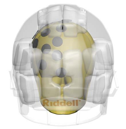
31 21 N). Each sensor was calibrated in the range of 0 to 15 N. The sensing area was mm 2 (based on a diameter of 9.5 mm). Therefore, the sensors had a pressure range of 0 to 210 kpa. This range was chosen based upon trial fitting of various helmets onto a volunteer. Linear curve fits were computed using Microsoft Excel, and the calibration for each sensor had good linearity (all R 2 >.98, Typically R 2 >.99). The calibration of the sensors was completed at a temperature of 22 C (72 F). The manufacturer s specification for these sensors reported a linearity of 3%. To assess the linearity error of the sensors in this measurement environment, the data from the sensor calibrations were analyzed. This was done by comparing the 3 sensor calibration curves for each sensor. The study indicated the average linearity error for each of the individual sensors was less than +/- 2% (95% confidence). The maximum error for each sensor was less than 7% (95% confidence). The maximum linearity error always occurred at the extreme low-end of the calibration curve The FIT Cap The sensors were incorporated into a Skull Cap (Under Armour, Baltimore, MD). The Skull Cap assembled to the measurement apparatus is referred to as the FIT Cap for this research. It was assumed that each volunteer s head would generate a symmetrical pressure distribution within the helmet; therefore, 24 sensors were assembled to, and covered half of, the Skull Cap. The nylon construction and portability of the Skull Cap allowed the FIT cap to be compliant to different volunteers heads and also easily transferable from volunteer to volunteer. Since the FIT cap stretches differently when worn by various volunteers, maintaining constant sensor spacing was not possible. The sensor array was established using a Hybrid III headform with the sensors having a 50
.")

32 22 mm centre-to-centre spacing. Figure illustrates the sensor array of the FIT cap. Figure illustrates a computer model of the sensor array on the Hybrid III headform and the projected sensing locations on a football helmet. Figure FIT Cap Figure FIT Cap Sensor Positions Projected onto Helmet The design of the FIT measurement system allowed for a large amount of sensor data to be acquired (24 sensors). It was portable and transferrable from volunteer to volunteer for this study. A custom computer program was written to acquire the sensor data (Appendix A). The program was approximately one thousand lines of code and allowed for the input of various data elements, selection of sensitivity, zeroing of sensors, acquisition, and real-time review of sensor data as well as the saving of data. The program was written with a Graphical User Interface (GUI) so the data could be input and acquired easily while taking measurements in the field. The FIT cap design and construction, coupled with the customized computer program, fulfilled the goal of this research project in developing an objective method of
33 23 measuring force between the head and the helmet, and the FIT Cap provides a possible method of quantifying helmet fitment. The FIT cap is also capable of monitoring the helmet s ability to distribute the load during an impact event. Since it was the intent for volunteers to wear the FIT cap, there was a potential for temperature to affect the readings because of the body temperature of the volunteers. The procedure (described in Chapter 2.3.3) would result in the FIT cap being worn by the volunteer for less than one minute; therefore, the temperature change of the sensor would likely be minimal. An uncertainty analysis was conducted to assess for potential temperature effects. The uncertainty analysis included the following assumptions: Linearity Error: 2% typical (7% maximum) Maximum temperature: 32 to 37 C Temperature Sensitivity: 0.36%/ C Calibration temperature: 22 C Based upon the maximum linearity error (7%) and the maximum temperature effects (ΔT MAX = 15 C), the maximum measurement uncertainty was calculated to be less than 9%. If the more typical linearity error was utilized for this calculation (2%) and field data regarding temperatures between padding and head is considered, the maximum temperature was likely less than 32 C (Farquhar et al from Appendix D). Based upon a linearity error of 2% and a ΔT = 10 C, the typical measurement uncertainty was calculated to be 4.1%. Due to the short amount of time that the FIT Cap would be on volunteer s heads, it is unlikely the sensor temperature would reach 37 C. Therefore, it is very likely the uncertainty in the measurements was less than the maximum calculated of 9% and more likely in the range of 4%.
34 Methods Field Study on Helmet Fitment Volunteers Various football teams belonging to the Essex Ravens Football Club (Ontario Varsity Football League [O.V.F.L.]) were asked to provide the volunteer data. The players on the football teams ranged from 14 to 20 years old and belonged to three separate teams (Junior, Junior Varsity, and Varsity). There were no identifiers recorded to provide any link between the volunteer and the data recorded. The measurements took place during spring training for the teams (April 27 th, 28 th, and 29 th 2010). The players helmets had each been fitted to the players by the Director of Football Operations and the Equipment Manager three weeks prior to the testing. This fitting procedure was reportedly completed by following the helmet fitting instructions provided by the helmet manufacturer. Volunteer testing requires approval of the Wayne State University Human Investigation Committee (HIC). The necessary human investigation courses were completed and a research proposal was then submitted to the HIC. An expedited approval was granted (Appendix B). The FIT cap (Chapter 2.2.2) was utilized to obtain measurement of the pressure between the volunteers heads and the padding of the helmet. Data for the volunteer testing was acquired using the Measurement Computing (USB 1616-HS) Data Acquisition board. The data sampling rate used was 100 Hz, and sensor data was averaged over a 10 second period. The averaged measurements were reported as a pressure.
35 Helmet Fitment Metrics The metric chosen for quantifying helmet fitment was pressure. There are no previously defined objective measures to quantify helmet fitment. Based upon the design objectives of a helmet, it is thought that there are two important parameters that should be maximized to result in a helmet fitting properly. It should: 1. Fit Evenly: This will optimize the helmet s ability to spread the load over the athlete s head. 2. Fit Tightly: This will assure that the helmet begins spreading the load immediately and also assist with helmet retention. A third parameter that is of importance is the ability of the helmet to fit the athlete comfortably. An uncomfortably fitting helmet may erroneously cause the athlete to select a larger size. Based upon the above, it appears the optimal fitting helmet would be a perfectly evenly fitting helmet (i.e., uniform pressure on the athlete s head) that is fitted as tightly as possible while still remaining comfortable. Based upon the above, it was necessary to derive a measurement index to quantify helmet fit. As a result of the above design criteria, the Average Fit Index (AFI) was developed. The AFI was developed to quantify the helmet s ability to fit an athlete evenly and comfortably. There are three components which make up the AFI: 1. Compute the average pressure of all the sensor data of each volunteer, herein referred to as P AVG [kpa], 2. Compute the standard deviation (SD) of the sensor readings, and
36 26 3. Compute the maximum sensor pressure for each volunteer, herein referred to as the P MAX [kpa]. The average fit index (AFI) is defined as: AFI = PAVG ± SD [unitless] P MAX The above relationship is presented as a means of quantifying how evenly a helmet is fitting the volunteer. A perfectly evenly fitting helmet would have an AFI = 1 ± 0. This means that each sensor has the exact same reading. This relationship was developed with the P MAX as the denominator. A more appropriate denominator can be the maximum comfortable pressure as reported by the volunteer athletes. If the maximum comfortable fitting helmet could be defined, then the AFI could reach values of greater than 1, indicating a helmet is fitting too tightly. However, there is currently no objective baseline data to establish at what tightness a helmet becomes too tight. In addition to the above parameters (P AVG, P MAX and AFI), a pressure distribution mapping of the helmet pressure on the volunteer s head was also completed for each volunteer Procedure On the dates of the study, athletes were randomly approached and asked if they would participate. The information sheet was reviewed once again with the athlete. The athlete was then asked if there were any questions and if they would like to continue to participate in the study. If the athlete chose to continue, the procedure was:
37 27 1. Record the helmet make, model, size, player position, and head circumference (for some participants). 2. The FIT cap was then put on the athlete s head and aligned so the centre line of the FIT cap was approximately in line with the sagittal plane. The sides of the FIT cap were stretched downward to the ear, the rear of the FIT cap was stretched downward to just below the occipital condyle, and the front was pulled down to approximately 2.5 cm above eyebrow level. 3. The FIT cap sensors were zeroed. 4. The players were asked to a put on their helmets as they normally would in a game situation and to secure all chin straps as they normally would. 5. Immediately upon securing the chin straps, measurements were started. The measurements were taken over a 10 second interval at a sampling frequency of 100 Hz and an average value was computed. 6. A bar graph indicating the evenness and tightness of fit was observed immediately upon completion of the measurements. This allowed for real time visualization of the individual measurements. 7. The helmet and FIT cap were then removed and the athlete returned to the field to resume training. 2.4 Helmet Fitment Results Volunteer Testing A total of 75 football players were tested. After reviewing the data, 63 of the 75 participants were deemed to have usable measurements. A testing issue was encountered on day 1 of the testing where the batteries for the FIT cap unknowingly became discharged, resulting in no data for the last 12 volunteers on that day.

38 28 Each of the volunteers was wearing a Riddell football helmet. There were 50 Riddell Revolution, 8 Riddell Revolution Speed, and 5 Riddell VSR4. Due to the time constraints during the volunteer testing, the head circumference measurement was omitted after the first day of the testing since it was delaying the throughput of volunteers. As a result, the first 20 volunteers head circumferences were measured. Each of the 20 volunteers measured had the appropriate sized helmet for the measured head circumference per Riddell Helmet fitting instructions. A large amount of measurement data was acquired (63 volunteers x 24 sensors = 1512 data points). The approximate sensor positions from the FIT cap are superimposed upon a model of the Hybrid III headform and illustrated in (Figure 2.4.1). The individual sensor data for all participants is shown in Figures 2.4.2a and b. Figure Sensor Positions

39 Note: All helmets tested are R iddell R iddell R evolution. 8 - R iddell R evolution S peed 5 - R iddell VS R 4 Pressure (kpa) Sensor Position Figure 2.4.2a Summary of Volunteer Data by Sensor Position Figure 2.4.2b Summary of Volunteer Sensor Data by Location
40 30 The FIT cap has 24 sensors on the left side of the cap. No pressure readings were taken on the right side of the head since it was assumed that the pressure distribution would be symmetrical. To visualize the pressure distribution on the headform, a linear interpolation between data points was applied. The 25 th, 50 th, 75 th, and 95 th percentile pressure maps of all the volunteer data are illustrated in Figures to Each illustrates a similar trend, showing higher pressure areas in the frontal and occipital regions. Appendix C includes a pressure map of the sensor data overlaid onto the computer model of the headform for each volunteer. kp Figure th Percentile Volunteer Pressure Distribution kpa kp Figure th Percentile Volunteer Pressure Distribution kp
 in the frontal area (59%) followed by the occipital area (29%).")
41 31 kp kp Figure th Percentile Volunteer Pressure Distribution kp kp Figure th Percentile Volunteer Pressure Distribution Volunteer P MAX s were also analyzed to assess the location of the maximum pressure on the volunteer. This is summarized in Table Most volunteers helmets had the P MAX (i.e., tightest fit) in the frontal area (59%) followed by the occipital area (29%). This was in good agreement with the pressure mapping data as illustrated previously. Although not formally documented during the testing, the volunteers were asked for their general impression of fitment. It was noted that general comments regarding the fitment
, the volunteers began to complain of an uncomfortably tight-fitting helmet.")
42 32 (tightness) of the helmet correlated with the pressure mappings. Also, if the P MAX on the volunteer exceeded approximately 69 kpa (10 psi), the volunteers began to complain of an uncomfortably tight-fitting helmet. Location of P MAX Number Percentage Frontal 37 59% Occipital 18 29% Temporal 5 8% Crown 3 5% Table Location of Maximum Pressure (P MAX ) The P AVG was computed for each volunteer. There was a substantial range in the P AVG for all volunteers (1.8 kpa to 26.8 kpa). Quartile P AVG values were 4.98 kpa, 8.09 kpa, kpa, and kpa (99 th percentile). Figure illustrates the P AVG for each volunteer. The 25 th, 50 th, 75 th, and 99 th percentile P AVG s are also shown for reference. Figure Average Pressure (P AVG ) by Volunteer
43 33 The Average Fit Index (AFI) was computed for each volunteer using all sensors within the FIT cap. The average AFI for all volunteers was 0.15 (± 0.25). The range for AFI values was 0.07 (± 0.2) to 0.3 (± 0.33). The design intent of the FIT cap was such that it could be moved from volunteer to volunteer efficiently and allow the volunteers to use their own personal helmet. Due to the inherent variation in the specific location of the sensors (relative to the helmet padding and the athlete s head), this could have had an effect on the computed AFI. A more representative AFI may have been obtained if the sensors could have been attached to specific locations within the helmet. Figure illustrates the effects of this design and the potential for some of the sensors to have been located in gaps between padding areas. As a result, some sensors may not have been contacting an area of the padding while the fit measurements were being recorded.


44 34 Figure Projected In-Helmet Sensor Positions
45 35 Given that the optimal AFI would be 1 ± 0, the computed AFI values indicate that the helmets worn by the volunteers in this set of field testing did not fit the volunteers evenly. This finding was confirmed by the pressure distribution plots. Since one of the primary design intents of the helmet is to spread the impact load, this data would suggest that an unevenly fitting helmet will cause the helmet s protective ability to be less than optimal. 2.5 Helmet Fitment Results Hybrid III Headform To determine the most appropriate helmet size to be used on the headform, two separate methods were utilized: 1. The Riddell Helmet Fitment Guide, and 2. Comparison of Helmet Fitment on Volunteers versus Helmet Fitment on the Hybrid III headform Helmet Size per Riddell Helmet Fitment Guide The circumference of the Hybrid III headform is 57.2 cm (22.5 ) (Hubbard 1974). The circumference of a Hybrid III headform was measured physically by using a string and also from a laser scan and a generated computer model of the Hybrid III headform. The measurement obtained from these methods was 58 cm. The helmet fitment guide was consulted for the Riddell Revolution, Riddell Revolution Speed, and Riddell Revolution IQ helmets. Each of these fitment guides indicates a large-sized helmet is appropriate for head circumferences between 55.9 cm and 59.7 cm (22 to 23½ ).
46 Volunteer Helmet Fitment versus Hybrid III Helmet Fit The second method for selecting the most representative size of helmet to be used on the Hybrid III headform was by utilizing a helmet size which achieves a representative P AVG, P MAX, and pressure distribution to the field test data obtained from the volunteer testing. The helmets selected for the analysis were a Riddell Revolution IQ HITS (size L) and a Riddell VSR4 (size M). The jaw pads in the large-sized helmet were inflated to assure contact occurred with the jaw area of the headform. The P AVG and P MAX results from these helmets fitted on the Hybrid III headform were compared to the volunteer fitment data. Based upon the comparison of the Riddell Revolution IQ (size L) helmet to the volunteer data, the P AVG from this helmet on the Hybrid III headform was representative of the 39 th percentile volunteer P AVG. The P MAX was also compared, and it had maximum pressures (38 kpa) that were representative of the 35 th percentile volunteer. A pressure map illustrating the Riddell Revolution IQ helmet (size L) on the Hybrid III headform versus the average and 50 th percentile volunteer fit data is illustrated in Figures (a to c). The pressure mapping indicates there was a more even fit in the volunteers in the temporal area; however, the helmet fit more evenly on the headform in the parietal region.
47 37 kpa kpa kpa Figure 2.5.1a 50th Percentile Volunteer kpa kpa Figure 2.5.1b Average Volunteer
48 38 kpa kpa Figure 2.5.1c Large-sized Helmet on Hybrid III Headform The Riddell VSR4 (size M) helmet was representative of the 99 th percentile P AVG on the volunteers tested. It also had a P MAX of 93 kpa that was representative of the 76 th percentile volunteer P MAX. Additionally, the P MAX measured on the Hybrid III headform with the Riddell VSR4 helmet are above the approximate pressure threshold at which volunteers began to indicate their helmets were fitting uncomfortably tightly (approximately 69 kpa). The Riddell Revolution IQ (size L) helmet and the Riddell VSR4 (size M) helmet compared to the volunteer P AVG data are illustrated in Figure


49 39 Figure Large- and Medium-sized Helmets on Hybrid III Headform versus Volunteer Data Pressure mappings comparing the medium-sized helmet on the Hybrid III headform to the volunteer test data are illustrated in Figures (a to c). It is clear from these pressure mappings that the medium-sized helmet on the Hybrid III headform is representative of the 90 th percentile volunteer pressure mapping. Therefore, a mediumsized helmet on the headform is not representative of how most volunteers wore their helmets, and its fit is also tighter than the level at which volunteers began to report that the helmet was uncomfortably tight.

50 40 kpa kpa Figure 2.5.3a 85 th Percentile Volunteer kpa kpa Figure 2.5.3b 95 th Percentile Volunteer
51 41 kpa kpa Figure 2.5.3c Medium-sized Helmet on Hybrid III Headform Based upon the P AVG, P MAX and the pressure mapping data, the appropriate size of helmet for the Hybrid III headform is a size large. The large-sized helmet produced a pressure distribution, P AVG, and P MAX that were more similar to the 50 th percentile values of the volunteer data. The medium-sized helmet on the headform produced P AVG values equal to the 99 th percentile volunteer, P MAX s (93 kpa) representative of the 76 th percentile volunteer, and the P MAX s were also greater than the threshold at which volunteers began to report an uncomfortably fitting helmet (69 kpa). The pressure mapped data for the medium-sized helmet on the headform is substantially tighter than the 50 th percentile or average volunteer. Therefore, the recommendation in the helmet fitment guide is that the large-sized helmet is appropriate for the headform circumference. The volunteer helmet fitment
52 42 measurements also indicate the fitment of the large-sized helmet on the headform is representative of how these football helmets are comfortably fitting athletes in field. 2.6 Conclusions Part I Helmet Fitment In summary, the following conclusions appear to be warranted: 1. An objective method of measuring pressure between the helmet and the head was designed and constructed. 2. A metric (The Average Fit Index AFI) was proposed to quantify how evenly a helmet is fitting an athlete s head. If sensors could be incorporated into a helmet, this metric would provide a more representative value of helmet fitment. 3. The pressure distribution, P AVG and P MAX between the head and the interior of the helmet, varied significantly within the athletes tested. 4. Volunteers generally reported an uncomfortable fitting helmet if a P MAX exceeded 69 kpa (10 psi). 5. Most helmets (59%) were found to fit the volunteers tightest in the frontal area; the second most common area of tight fit was in the occipital area (29%). 6. A medium-sized helmet on the Hybrid III headform is not representative of how most volunteers wore their helmets, and its fit is above the pressure threshold at which the volunteers reported that the fitment was uncomfortable. 7. The recommendations in the helmet fitment guide, and also our helmet-tohead volunteer pressure measurements, indicate the appropriate Riddell Revolution IQ helmet size for the Hybrid III headform is a large.
53 43 Chapter 3 The Effects of Helmet Fit on Head Impact Response and Recorded Helmet Accelerations by a Riddell Revolution IQ HITS Helmet 3.1 Introduction Two of the primary design criteria for helmet protection (Newman, 1993) are to: 1. Cushion loading to the head, and 2. Spread the load over a larger area. Based upon the above, a well-fitting helmet is essential to optimize helmet performance. In Chapter 2, an apparatus for the objective measurement of helmet fitment was described. The field testing data that were also presented indicated that helmet fit among athletes varied in tightness and evenness of fit. Chapter 2 has also indicated that a large-sized helmet is more representative of the 50 th percentile volunteer than the medium-sized helmet on the Hybrid III headform. The medium-sized helmet has a tighter P AVG than the 85 th percentile volunteer, and the P MAX were greater than the threshold at which volunteers began to report an uncomfortable fit. Despite the importance of an even- and tightly-fitting helmet, the effects of helmet fit on performance do not appear to have been extensively studied. Furthermore, previous research has been conducted with a large-sized (Pellman et al., 2003a; Pellman et al., 2003b; Pellman et al., 2006a) or a medium-sized helmet (Beckwith et al., 2011; Rowson et al., 2011) on the Hybrid III headform. Chapter 2 has illustrated that a large-sized helmet is the appropriate helmet based upon the Riddell helmet s fitting instructions and by the field study results of how athletes comfortably wore football helmets. The goals
54 44 of the research presented in this chapter are to, 1) Compare the effects on helmet performance in a loose-fitting condition (representative of the 50 th percentile volunteer) versus a tighter-fitting condition and 2) Evaluate the effects of helmet fitment on the HIT System in terms of measurement errors in comparison with the Hybrid III headform reported response parameters. 3.2 Materials and Methods Equipment The impact testing conducted for this research was completed at the Wayne State University (WSU) Sports Biomechanics Laboratory. For impact testing, a Hybrid III 50 th percentile male headform was mounted on the Hybrid III 50 th percentile male neck. The helmeted headform was impacted using a pneumatic linear impactor (Biokinetics and Associates, Ltd., Ottawa, Ontario, Canada) (Figure 3.2.1). The helmeted headform was mounted to a linear bearing table which allowed for translational movement of the assembly subsequent to the impact. The linear impactor design was previously described (Pellman et al., 2006a). Impacting the helmeted Hybrid III headform with the pneumatic linear impactor resulted in the response of the helmeted headform representing kinematic responses of the head when compared to the real-life game impacts. The National Operating Committee on Standards for Athletic Equipment (NOCSAE) is also in the process of adopting this testing procedure for its evaluation of football helmets ( 2011).

55 45 Figure Biokinetics Linear Impactor The helmet utilized for this testing was the Riddell Revolution IQ HITS helmet (size Large) (Riddell, Elyra, Ohio). The IQ HITS helmet was chosen for this study for a variety of reasons: 1. Riddell is the official helmet of the NFL and is largely used by collegiate and high school football athletes. 2. All helmets tested in the volunteer fitment study were Riddell (Chapter 2). 3. The Revolution IQ helmet (size Large) fitted onto the Hybrid III headform is comparable to the 50 th percentile average pressure and maximum pressures recorded during volunteer testing of helmet fitment (Chapter 2) and is the size recommended by the Riddell helmet fitting guide based on the circumference of the headform. 4. The HIT System helmet is equipped with helmet-mounted accelerometers which are reported to have the capability of measuring various response parameters when worn by a player. At the onset of this research, it was
56 46 hypothesized that fitment (tightness and evenness) of the helmet on a headform (or a player) could affect the reported response parameters from the HIT System helmet Data Acquisition and Measurement The headform was instrumented with 9 single axis accelerometers, oriented in the array (Padgaonkar et al., 1975). This array permitted the measurement of head linear and angular acceleration and angular velocity. Impactor speed was measured at the impactor velocity trap. The Hybrid III upper neck load cell was utilized to measure neck forces and moments (Denton, Plymouth, MI., 6-axis load cell model 1716). The above data were acquired using the TDAS-Pro (Diversified Technical Systems [DTS Inc.]) data acquisition system at a rate of 10 khz. These data were sent through an anti-aliasing filter prior to digitization and were subsequently filtered per SAE J-211 (SAE, 1995) using a CFC1000 filter. During the analysis of the data, it was noted that ringing occurred in some of the accelerometers. A band-pass filter (0.1 to 1000 Hz) was used to remove the ringing, and the data were re-checked to ensure that the ringing had been removed and that there was no phase shift. The Hybrid III headform was equipped with the FIT Cap (Chapter 2). The attachment and hardware signal conditioning for the FIT Cap are previously described. The sensors and channels to which each sensor was attached remained unchanged for this testing. Data from the FIT Cap were acquired using the USB 1616HS-4 (Measurement Computing Corporation., Norton, MA) data acquisition system at a rate of 1000 Hz. A summary of the sensors and filtering is illustrated in Table
57 47 Instrumentation Description Filter Head Accelerations Endevco K Band-pass [ Hz] Upper Neck Moment (X,Y,Z) Denton (Model 1716) CFC1000 Upper Neck Force (X,Y,Z) Denton (Model 1716) CFC1000 Headform Surface Pressure Tekscan (Model Flexiforce-A201) - Table Summary of Sensors and Filtering for Impact Testing The Riddell Revolution IQ helmet was equipped with the HIT System equipped with the latest Mx Encoder with six single axis accelerometers. The trigger on the helmet was set to record for 40 ms (8 ms pre-impact, 32 ms post-impact) if the impact exceeded 10 g. The data from the HIT System were transferred wirelessly to a laptop computer, uploaded to, and processed by the Redzone software. All calculations were completed by the Redzone software Test Conditions and Impact Orientations Pellman (Pellman et al., 2003b) have summarized common impact orientations resulting in concussion to players in the NFL. Craig (Craig, 2007) has also proposed that A and A impact orientations to the facemask should also be studied since these impacts resulted in a large fraction of reported concussions and also resulted in chin strap loading. Some of these impact orientations have been considered for NOCSAE football helmet testing, and a new standard is currently in the proposed status ( 2011). The NFL has also undertaken a helmet testing program (Helmet Concussion Assessment Program [HCAP]). A presentation summarizing the impact orientations to be considered in HCAP is in Appendix D. Some of the impact conditions illustrated in this presentation
. The impact conditions used were based upon the original research by the NFL Subcommittee (Pellman et al., 2003b). Figure 3.2.2 Impact Conditions Since the focus of this study was the effect of")
58 48 were used for this impact testing (Figure 3.2.2). The impact conditions used were based upon the original research by the NFL Subcommittee (Pellman et al., 2003b). Figure Impact Conditions Since the focus of this study was the effect of fitment on the performance of a football helmet on the headform, the impact orientations were chosen specifically to impact areas of differing tightnesses of fit. For this reason, conditions F, UT, C, and D were chosen. Conditions F and D impact the tightest (front) and second tightest (rear) locations on the headform while Condition C impacts the more loosely-fitting area on the headform. Condition UT is impacting the helmet in the jaw pad, an area to which the FIT cap does not extend. Each of these impact orientations resulted in a direct impact to the helmeted headform as opposed to a glancing blow. The facemask impacts A, A, A and B were

59 49 omitted to avoid damage to the facemask and since they did not result in a direct impact to the shell of the helmet. A summary of the Hybrid III neck orientations and the base table locations utilized for this research are summarized in Table 3.2.2, and the coordinate systems for the table setup are illustrated in Figure Impact Condition Neck Orientation Table Location α β X Y Z F 0 deg. 15 deg. 200 mm 283 mm 478 mm* UT -90 deg. 0 deg. 142 mm 283 mm 558 mm C -105 deg. 11 deg. 173 mm 283 mm 536 mm D -157 deg. 11 deg. 172 mm 283 mm 536 mm *The table height was adjusted to prevent striking the facemask. Table Hybrid III Neck Orientation and Table Location for Linear Impactor Testing Figure Linear Impactor Table Co-ordinate System

. Figure 3.2.")


60 50 Each of the impact conditions are further illustrated in Figures (a to d). Figure 3.2.4a Impact Condition F Figure 3.2.4b Impact Condition UT Figure 3.2.4c Impact Condition C Figure 3.2.4d Impact Condition D
61 51 Tightness of helmet fit was analyzed for this testing. Varying helmet fit was conducted by increasing the bladder pressure(s) in the helmet. The loose -fitting condition (air only in the jaw-pad bladders) was used as a baseline for the analysis. The jaw-pad bladders were inflated until they contacted the headform. The looser fit condition represented the 39 th and 35 th percentile P AVG and P MAX volunteer fitment data. The loose-fitting condition also correlated well with the overall pressure distribution between the helmet and the headform of the average volunteer (Chapter 2). The tightfitting condition was chosen to be greater than the 100 th percentile volunteer fitment data. When the bladders for the helmet were inflated for the tight-fitting condition, it also resulted in a more uniform helmet fit on the headform. The bladder pressure in the tightfitting condition could not be controlled well, and the goal was simply to create a fit condition that was much tighter than the comfortable volunteer fitment. This was done to provide as great a spread in helmet tightness as possible. In total, four orientations were used (F, UT, C, and D). Loose- and tight-fitting conditions were considered, and each test was repeated a minimum of five times. There were 48 tests in total. The tests were conducted by targeting an impact speed of 9.3 m/s. This test speed was chosen because the NFL Subcommittee research (Pellman et al, 2003b) has described this as being the average impact velocity resulting in concussion (9.3 m/s ± 1.9 m/s). The number of tests and average impact velocity for each condition is illustrated in Table
62 52 Impact Condition Loose Condition Tight Condition N Impact Speed (m/s) N Impact Speed (m/s) F (+/ ) (+/ ) UT (+/ ) (+/ ) C (+/ ) (+/ ) D (+/ ) (+/ ) Table Summary of Linear Impactor Test Speeds by Impact Condition Helmet Performance Metrics To assess the effects of helmet fitment on headform response and also the effects of helmet fitment on reported response parameters from the HIT System, common injury measures were utilized. These are discussed below. Peak Linear Acceleration Injury Measures Linear acceleration injury measures related to head impacts have been widely studied. Studying head injury measures using linear accelerations are reported to be desirable due to the ease of measurement. Various head injury assessment reference values have been developed and have been associated with brain injury as well as skull fracture. The Wayne State Tolerance Curve (WSTC) (Lissner et al., 1960) and Japan Automotive Research Institute (JARI) Head Tolerance Curves (Ono et al., 1980) were developed in which linear acceleration was expressed as a function of impact duration. Pellman (Pellman et al., 2003b), Zhang (Zhang et al., 2004), King (King et al., 2003), Funk (Funk et al., 2007), Funk (Funk et al., 2011), and Rowson (Rowson et al., 2011) have proposed concussion injury thresholds based upon helmeted football impacts.
63 53 Pellman and Funk have also proposed concussion risk functions to predict the probability of injury. The concussion injury thresholds proposed by Pellman, Zhang, and King are based upon reconstruction of injurious impacts in the NFL Studies; whereas, the thresholds proposed by Funk and Rowson are based upon HIT System data. A summary of the proposed criteria is illustrated in Table Peak Acceleration (g) Probability of Concussion Pellman 81 50% King 79 50% Zhang 82 50% Funk (2007) % Funk (2011) % Rowson (2011) % Table Summary of Proposed Peak Linear Acceleration (PLA) Based Injury Criterion Head Injury Criterion (HIC) HIC is an injury criterion that is based upon linear acceleration and the Wayne State Tolerance Curve. It is traditionally used for the assessment of head protection in the automotive industry when an impact occurs with an interior vehicle component. It is utilized as a measure of head injury assessment in various Federal Motor Vehicle Safety Standards (FMVSS). When applying HIC in the automotive testing environment, it has been recommended that the duration over which HIC is calculated is less than 15 ms (HIC15) (Prasad et al., 1985). The majority of the data presented by Prasad have HIC duration < 10 ms. HIC15 will be considered here. The expression to calculate HIC15 is: HIC 15 1 = ( t2 t1 ) 1 2 t t t t 1 2 ar( t) dt 2.5
64 54 Gadd Severity Index (GSI) GSI is a head injury criterion that it based upon linear acceleration and the Wayne State Tolerance Curve. It is traditionally used for the assessment of helmet performance in the NOCSAE standards and was originally proposed by Gadd (Gadd, 1966). The expression to calculate GSI is: GSI = T a( t) 2.5 dt Rotational Acceleration Rotational acceleration was also considered as a helmet performance measure. It has been shown to be related to brain strain. Brain strain and strain rate have shown a strong correlation to concussion in the reconstruction of helmet impacts in the NFL studies (Viano et al, 2005a; Zhang et al., 2004). A summary of proposed angular accelerationbased criteria is illustrated in Table Ang. Accel. (rad/s 2 ) Probability of Concussion Pellman % King % Zhang % Rowson 6383 (@28.3 rad/s) 50% Funk % Table Summary of Proposed Peak Angular Acceleration (PAA)-Based Injury Criterion
65 55 Pressure Distribution on the Headform Surface Newman (Newman, 1993) has identified that the primary design functions of a helmet are to cushion an impact to the head and to spread the load over a larger area. These design goals are consistent with Eppinger s (Eppinger, 1993) Maxims for Good Restraint Performance and Design, wherein he indicates it is desirable to distribute forces over the greatest area. Pressure is not a typical metric utilized for helmet performance measures; however, pressure or force is considered a headform input parameter rather than a response parameter of the headform (e.g., acceleration-related parameters). Based upon the above noted design goals of a helmet, it would appear that an appropriate metric to evaluate helmet performance is pressure distribution. Due to the implementation of the FIT Cap (Chapter 2) in this research, head surface pressure can be measured and evaluated as a performance metric Analysis of Data An analysis of the headform accelerometer and FIT Cap data was conducted using the Diadem Software (Version 11.1, National Instruments, Austin, Texas). The headform accelerometer data and the upper neck load cell data were captured with the same data acquisition system and, therefore, synchronized. The FIT Cap data were acquired using separate data acquisition equipment, and the data were not synchronized with the acceleration data ; therefore, a direct temporal comparison of pressure and acceleration could not be made. The HIT System data were acquired through use of the Redzone Software (Simbex, Lebanon, NH). Time-history was not available, and only maximum values for the various injury criteria were reported.
66 56 Statistical analysis was conducted on the acquired data. Descriptive statistics (mean and standard deviation) were calculated using Microsoft Excel (Microsoft, Seattle, WA). Comparative plots were also computed, where applicable, to analyze the differences between the HIT System reported data versus the headform reported values. In this testing, the headform data were considered to be the gold standard. The relative error plots were calculated based upon the equation: ( HITS H3) Re lativeerro r( RE) = H In addition to the relative error calculation, the absolute error between the HIT System data and the headform data was also calculated. Absolute error is the absolute value of the relative error and was used to compare the tight-fitting versus loose-fitting conditions for each impact location. AbsoluteEr ror ( HITS H 3) ( AE) = 100 H 3 A linear regression analysis was undertaken to assess whether there was a correlation that could be made between the paired samples (i.e., HITS data versus Headform data). A Pearson Correlation Coefficient, R, was utilized to assess the correlation between the samples, and the significance of the correlation was also assessed. A multiple sample t-test approach was undertaken to analyze the paired samples (e.g., HITS data versus Headform data and Headform data tight-fit versus Headform data loose-fit). Two-tailed t-tests were used to assess whether there were significant differences between the paired samples. The t-statistic is a measure of the difference in means of two populations divided by the standard deviation of the mean. A 95%
67 57 confidence interval of the paired differences was used to assess significance. When one uses this approach, if the significance (sig.) is less than 0.05, there is a high probability of error in the HIT System. 3.3 Results A total of 48 tests were performed using the linear impactor. Twenty-five of the tests were conducted under the loose-fitting condition and twenty three tests were conducted with the air bladders inflated to a tight (but uncomfortable ) and more uniform-fitting condition. When comparing the HIT System data versus the headform data, there were only 22 tests recorded using the HIT System in a looser-fitting condition and 19 tests recorded in the tighter-fitting condition. The HIT System filtered out various impacts due to its built-in filtering algorithms and, therefore, did not record these impacts. Four additional HIT System records were filtered out of the HIT data set by the built-in algorithms but were recoverable through correspondence with Simbex. Therefore, from the original dataset, 11 of the 48 impacts (22.9%) were removed from the dataset by the HIT System algorithms. The focus of the analysis of the results was a comparison between the loose- and tight-fitting conditions and their effect on helmet performance as well as reported parameters from the HIT System versus the accelerometer data from the headform Headform Response and Tightness of Helmet Fit The bladders in the helmet were used to control the tightness of fit. Table summarizes the descriptive statistics and the results of a student t-test comparison of tightness of helmet fit versus headform response for all impact conditions. Tightness of
68 58 helmet fit had an effect on helmet performance. The tight-fitting condition also resulted in a more uniform-fitting helmet. As the tightness of fit increased, the linear acceleration related performance parameters increased (i.e., HIC, GSI, and Peak Linear Acceleration), but when all impact conditions were averaged, the differences were not significant. Peak Angular Acceleration (PAA) was found to be significantly lower (t=3.226, p=0.003) in the tighter and more uniform-fitting condition. Paired Samples Statistics Std. Std. Error Mean N Deviation Mean LooseHIC TightHIC LooseGSI TightGSI LoosePLA TightPLA LoosePAA TightPAA LoosePAV TightPAV Significance Mean Difference t Sig. (2-tailed) Table Comparison of Loose-Fitting versus Tight-Fitting Helmet The individual impact locations were also analyzed. As the tightness of fit increased, linear acceleration-related performance parameters (i.e., HIC, GSI, and Peak Linear Acceleration) increased for impact conditions C and F. In impact condition UT, there were no significant findings with regard to any of the response parameters; however, these parameters still showed an increase of the mean. In impact condition D, the performance parameters increased. The significance level (95% Confidence Interval [CI]) of the difference by impact location is summarized in Table As tightness of
69 59 fit increased, it had the opposite effect on angular acceleration. The tight- (and more uniform) fitting condition resulted in lower angular accelerations in impact conditions C, F, and UT. There were substantial differences in angular acceleration in impact condition F (32% reduction in angular acceleration). Location HIC15 GSI PLA PAA Ang Vel D C F UT Table Loose- versus Tight-Fitting Condition, Significance Figures to illustrate the loose-fitting condition and the tight-fitting condition versus the selected performance metrics. Conditions which resulted in a statistically significant finding are shown with an asterisk (*). Average values are shown in these plots, and the error bars represent ±1 standard deviation. 300 Loose Tight HIC * * * D C F UT Impact Condition Figure HIC: Loose- versus Tight-Fitting Condition
70 Loose Tight GSI * * * D C F UT Impact Condition Figure GSI: Loose- versus Tight-Fitting Condition Loose Tight PLA [g] * * * D C F UT Impact Condition Figure PLA: Loose- versus Tight-Fitting Condition
71 Loose Tight PAA [rad/s 2 ] * * * D C F UT Impact Condition Figure PAA: Loose- versus Tight-Fitting Condition 60 Loose Tight 50 Ang. Velocity [rad/s] * * D C F UT Impact Condition Figure Angular Velocity: Loose- versus Tight-Fitting Condition
72 62 Peak surface pressure data that occurred during the impact were also analyzed (Figure 3.3.6), and there were significant differences in the test results in two of the four impact orientations (C, D). Peak pressure increased in each of these two conditions as tightness of fit increased Loose Tight 1000 Peak Pressure [kpa] * * D C F UT Impact Condition Figure Peak Surface Pressure: Loose- versus Tight-Fitting Condition Peak pressure varied substantially depending on impact orientation regardless of the fit condition. In impact condition F, the peak pressure during the impact was substantially higher when compared to the other impact conditions. The fitment on the front of the headform also had higher surface pressures than the rest of the headform. The substantially higher surface pressures observed during the impact testing may have been the result of a combination of parameters. These are listed below: Stiffness of padding in the frontal area,

 that helmet fit in the frontal area of the headform was substantially tighter than all other areas of the headform.")
.")
73 63 A tighter fit in the frontal area, and/or Ineffective spread of the impact load on the headform. Firstly, measuring the stiffness of the padding in various areas of the helmet was not a goal of this research and, therefore, was not investigated; however, manual compression of the padding indicated that the frontal padding appeared to be stiffer than the padding in other areas of the helmet. Secondly, it was summarized previously (Chapter 2) that helmet fit in the frontal area of the headform was substantially tighter than all other areas of the headform. This finding was also consistent with the volunteer fitment testing. The tight-fitting condition also resulted in a more uniform-fitting condition. To assess the ability of the helmet to spread the load over the frontal area of the headform, we compared a tight- and loose-fitting condition of the helmet in impact condition F (Figures 3.3.7a and b). In the loose-fitting condition, the pressure is concentrated in the frontal area of the helmet and it is distributed primarily in the sagittal plane. The tighter and more evenly fitting condition distributed the impact over the entire anterior aspect of the headform. kpa Figure 3.3.7a Peak Pressure Loose- Fitting Condition kpa Figure 3.3.7b Peak Pressure Tight- (Uniform) Fitting Condition
74 64 The tighter (and uniform) fitting helmet resulted in a more even spread of the impact forces, and as a result, there was an increase in linear acceleration (18%). There was also a nominal increase in angular speed (1%), and a substantial decrease in angular acceleration (32%) for impact condition F. A representative impact event is illustrated in Figure 3.3.8a. This finding indicates that a more uniform-fitting helmet is more efficient at spreading the impact load over a larger area. The more evenly spread loading pattern results in the headform undergoing a more linear response to the impact and substantially reduces the angular acceleration component. The tighter and more uniform-fitting helmet also resulted in higher angular speeds; however, the rate at which the angular speed increased was more linear. This is also illustrated in the angular acceleration curve where, in the loose-fitting condition, there is a slow onset of the angular acceleration, followed by a steep increase. These differences also illustrate that a tighter and more uniform-fitting helmet applies protection to the head earlier during the impact event. Similar response characteristics were noted in impact conditions UT, C, and D (Figures 3.3.8b to d). The response parameters in these impact conditions did not illustrate as substantial a decrease in angular acceleration response. This may be a result of the frontal area being the tightest fitting area on the headform.
75 65 Figure 3.3.8a Impact Condition F
76 66 Figure 3.3.8b Impact Condition UT
77 67 Figure 3.3.8c Impact Condition C
78 68 Figure 3.3.8d Impact Condition D
79 69 In three of the four impact conditions above (C, D, and UT), there was a secondary peak in the linear acceleration data which occurred approximately 8 to 10 ms after the initial peak acceleration. This condition was present in all tests, loose and tight, for conditions C, D, and UT. Analysis of the data indicates the signals from accelerometers OZ, XZ, and YZ of the array displayed this characteristic. The sensing axis from each of these accelerometers was the z-axis. In the accelerometer data, there was a relatively large peak in the negative (upward) z acceleration data at this time. The Fz peak tensile load in the upper neck load cell data also correlated with the timing of this peak upward acceleration (Figure 3.3.9). Since each of these 3 accelerometers was mounted on a different mounting location, and the Fz peak load also correlated with this time, it does not appear that the secondary peak is an artifact of improper accelerometer mounting.
80 70 Figure Secondary Acceleration Peak
81 71 Craig (Craig, 2007) conducted an analysis of jaw loading due to chin strap interaction using a similar setup to this linear impactor testing. Generally, peak linear accelerations in the testing conducted by Craig occurred at approximately 5 10 ms after the initial impact, and the peak jaw loading occurred at approximately 15 to 20 ms after the initial impact. The three impact conditions conducted by Craig were all frontal impact conditions (A, A and A ) to the facemask area. Based upon the Craig data, it appears the secondary peak in the linear acceleration data is associated with chin strap loading through the jaw of the headform Head Response vs. Reported HITS Data Peak response parameters only were recorded by the HIT System. Time history data were not available. A comparison of the data from the individual tests is illustrated in Figures a to h. These data illustrate that there are differences in the HITSreported values for each of the headform related, performance characteristics: HIC, GSI, peak linear acceleration (PLA), and peak angular acceleration (PAA). For HIC and GSI, the values varied from being over-reported by 50% to being under-reported by 79%. Peak linear acceleration was generally within ±25% with the exception of impact condition D where errors reached 98% for the tight-fitting condition. Peak angular acceleration was substantially over-predicted by the HITS. Error in angular acceleration varied between -59% and approximately 203%. This is despite the fact that the HIT System only reports angular acceleration in two of the three axes.
82 72 100% 75% 50% HIC [E rror (% )] 25% 0% -25% L oose L oose L oose L oose L oose L oose L oose L oose L oose L oose L oose L oose L oose L oose L oose L oose L oose L oose L oose L oose Tight Tight Tight Tight Tight Tight Tight Tight Tight Tight Tight Tight Tight Tight Tight Tight Tight Tight Tight C C C C C D D D D F F F F F UT UT UT UT UT UT C C C D D D D D F F F F F F UT UT UT UT UT -50% -75% -100% Figure a HIC: Relative Error HITS vs Hybrid III Test Condition, Average Absolute Error Condition F-L, 51% Condition F-T, 25% Condition C-L, 26% Condition C-T, 20% HIT System HIC Condition UT-L, 32% Condition UT-T, 44% Condition D-L, 28% Condition D-T, 24% HIII HIC Figure b HIC: HIT System vs. Hybrid III Data and Absolute Error
83 73 100% 75% 50% GS I [E rror (% )] 25% 0% -25% L oose L oose L oose L oose L oose L oose L oose L oose L oose L oose L oose L oose L oose L oose L oose L oose L oose L oose L oose L oose Tight Tight Tight Tight Tight Tight Tight Tight Tight Tight Tight Tight Tight Tight Tight Tight Tight Tight Tight C C C C C D D D D F F F F F UT UT UT UT UT UT C C C D D D D D F F F F F F UT UT UT UT UT -50% -75% -100% Figure c GSI: Relative Error HITS vs Hybrid III HIT System GSI Test Condition, Average Absolute Error Condition F-L, 52% Condition F-T, 25% Condition C-L, 8% Condition C-T, 36% Condition UT-L, 38% Condition UT-T, 43% Condition D-L, 30% Condition D-T, 14% HIII GSI Figure d GSI: HIT System vs. Hybrid III Data and Absolute Error
84 74 100% 75% 50% PL A [E rror (% )] 25% 0% -25% L oose L oose L oose L oose L oose L oose L oose L oose L oose L oose L oose L oose L oose L oose L oose L oose L oose L oose L oose L oose Tight Tight Tight Tight Tight Tight Tight Tight Tight Tight Tight Tight Tight Tight Tight Tight Tight Tight Tight C C C C C D D D D F F F F F UT UT UT UT UT UT C C C D D D D D F F F F F F UT UT UT UT UT -50% -75% -100% Figure e PLA: Relative Error HITS vs Hybrid III Test Condition, Average Absolute Error Condition F-L, 12% Condition F-T, 13% Condition C-L, 20% Condition C-T, 7% HIT System PLA (g) Condition UT-L, 10% Condition UT-T, 13% Condition D-L, 19% Condition D-T, 74% HIII PLA (g) Figure f PLA: HIT System vs. Hybrid III Data and Absolute Error
85 75 200% 175% 150% 125% 100% 75% 50% PAA [E rror (% )] 25% 0% -25% -50% L oose L oose L oose L oose L oose L oose L oose L oose L oose L oose L oose L oose L oose L oose L oose L oose L oose L oose L oose L oose Tight Tight Tight Tight Tight Tight Tight Tight Tight Tight Tight Tight Tight Tight Tight Tight Tight Tight Tight C C C C C D D D D F F F F F UT UT UT UT UT UT C C C D D D D D F F F F F F UT UT UT UT UT -75% -100% Figure g PAA: Relative Error HITS vs Hybrid III HIT System PAA (rad/s 2 ) Test Condition, Average Absolute Error Condition F-L, 23% Condition F-T, 126% Condition C-L, 58% Condition C-T, 61% Condition UT-L, 49% Condition UT-T, 72% Condition D-L, 103% Condition D-T, 142% HIII PAA (rad/s 2 ) Figure h PAA: HIT System vs. Hybrid III Data and Absolute Error
86 76 Table summarizes the average absolute error for the loose- and tight-fitting conditions as well as the overall absolute error. Condition Fit HIC GSI PLA PAA All Loose 33% 32% 14% 55% All Tight 29% 28% 28% 106% All All 32% 30% 21% 80% Table Summary of HIT System Absolute Error Table summarizes the headform response data versus HIT System response data as well as the paired samples correlation. The paired samples analysis was conducted by comparing the loose- and tight- fitting conditions. The data in this table are a combination of the tight- and loose-fitting conditions. There are apparent differences in the mean values of the response parameters reported by the HITS versus the headform data. The standard deviation of the HITS is substantially greater than the standard deviations reported by the headform (2.6 to 2.9 times greater). The paired samples correlation indicated there was not a strong correlation between any of the HITS and headform response parameters. GSI had a significant correlation; however, the correlation coefficient was low (r =0.386, sig = 0.012). A paired samples test was conducted on the combined HITS versus headform reported data. The HITS underpredicted HIC by a mean difference of 45.8 (t=-3.669, p = 0.001), under-predicted GSI by a mean difference of 88 (t=-6.278, p=0.000), and over-predicted peak angular acceleration by a mean difference of 2287 rad/s 2 (t=11.647, p=0.000). HITS peak linear acceleration was slightly greater with a mean difference of 7.9 g (t=2.595, p=0.013).
87 77 Paired Samples Statistics Correlation Mean N Std. Deviation Std. Error Mean Correlation Sig. HITSHIC H3HIC HITSGSI H3GSI HITSPLA H3PLA HITSPAA H3PAA HITSHIC - H3HIC HITSGSI - H3GSI HITSPLA - H3PLA HITSPAA - H3PAA Mean Std. Deviation Paired Differences 95% Confidence Interval of the Difference Std. Error Mean Lower Upper t Df Sig. (2-tailed) Table Summary of HIT System versus Hybrid III Data (Combined Tight and Loose) Tightness of helmet fit had an effect on the HITS reported parameters versus the headform response. In the loose-fitting condition, the HITS PLA was not statistically different from headform PLA (t=1.303, p=0.207); however, HIC, GSI, and PAA were (Table 3.3.5).
88 78 Paired Samples Statistics Correlation Std. Mean N Std. Deviation Error Mean Correlation Sig. HITSHIC H3HIC HITSGSI H3GSI HITSPLA H3PLA HITSPAA H3PAA Paired Differences HITSHIC - H3HIC HITSGSI - H3GSI HITSPLA - H3PLA HITSPAA - H3PAA Mean Std. Deviation 95% Confidence Interval of the Difference Std. Error Mean Lower Upper t df Sig. (2- tailed) Table Summary of HIT System versus H3 Data (Loose Condition) In the tight-fitting condition (Table 3.3.6), PLA reported by HITS was higher than PLA reported by the headform (t=2.303, p=0.033). The tight-fitting condition also resulted in HITS data more closely representing the headform-reported HIC (t=-1.542, p=0.14), GSI (t=-2.828, p=0.011), and PLA; however, GSI and PLA were still significantly different. PAA remained significantly different for this condition. In addition to the improvements to the t-statistic, a tighter fitting helmet also resulted in HIT
89 79 system PLA correlating with headform PLA (r=0.739, sig < 0.001). The standard deviations for HIC and GSI of the HIT system reduced in the tight-fitting condition (relative to looser-fitting condition); however, standard deviations of PLA and PAA increased. Paired Samples Statistics Correlation Mean N Std. Deviation Std. Error Mean HITSHIC H3HIC HITSGSI H3GSI HITSPLA H3PLA HITSPAA H3PAA Correlation Sig. (2-tailed) HITSHIC - H3HIC HITSGSI - H3GSI HITSPLA - H3PLA HITSPAA - H3PAA Mean Paired Differences 95% Confidence Interval of the Difference Std. Std. Error Deviation Mean Lower Upper t df Sig. (2- tailed) Table Summary of HIT System versus Hybrid III Data (Tight Condition)
90 80 Chapter 4 Discussion and Limitations This research study provided an objective method of measuring pressure between the head and the helmet. An index was proposed to quantify how tightly and evenly a helmet fits a head. The research has also quantified how football helmets fit on volunteer players as well as on the Hybrid III headform. Finally, it has discussed the effects of helmet fitment on various Hybrid III headform response parameters and how helmet fitment affects the ability of the HIT system to predict headform responses accurately. Various statistically significant findings were noted. 4.1 A Method of Measuring Helmet Fit A method of objectively measuring the pressure between the helmet padding and an athlete s head (or a headform) has been established. The FIT cap is a portable system which allowed for transferability from volunteer to volunteer. The design and construction of this FIT cap, as well as computer programming undertaken, allowed for a large number of volunteer data to be captured without significantly interrupting football teams practice schedules. Up until now, helmet fitment has been reported as being an important aspect of helmet protection. However, there has been no objective method of measuring how evenly or how tightly a helmet fits. Published fitting guides appear to rely purely on a subjective method of helmet fitment. This research provides for a means to quantify helmet fit objectively and to monitor how tightly and evenly a helmet is fitting the athlete. The fitting method and apparatus that were developed are economical, and the potential for a commercial helmet fit system does exist. This system could aid helmet manufacturers in achieving a more uniform fit on the athletes who wear the helmets. This, in turn, would provide insight into this major boundary condition for
91 81 helmet manufacturers and allow the manufacturers to focus on improving padding and/or other methods to increase helmet performance. The major limitation regarding the current FIT system design is that it was designed to be a portable device for the purpose of collecting volunteer fitment data while the volunteers wore their own, previously-fitted helmets. As discussed, this led to the potential for sensors not to contact the interior padding of the helmet since many helmets have air gaps between the padding. Due to the small, lightweight, and low cost design of the system, it could be incorporated directly into a helmet design. If incorporated into a helmet, the system could also provide impact-related data which could be used as an input for finite element modeling of the brain. 4.2 Volunteer Helmet Fitment The goals of the volunteer helmet fitment measurements were to: 1. Quantify the level of fitment (tightness and evenness) which existed for current football players who had reportedly been fitted according to the helmet manufacturer s recommended practice and 2. Assess the fitment of a helmet on the Hybrid III headform. In total, 63 volunteers were tested, varying in ages from 14 to 20 years old. The results of this study indicate helmets fit volunteers in varying degrees of tightness and evenness. Most volunteers had the tightest-fitting area on the frontal portion of the head (59%). The second most common region with a tight-fitting section was in the occipital area (29%). Volunteers within this study reported an uncomfortable fit when the FIT cap pressure readings exceeded 69 kpa (10 psi). It was commonly observed in these volunteers that there were red markings or indentations on the volunteers foreheads to
92 82 complement their comments of tightness of fit. To date, this study appears to be the only volunteer-based study that has objectively measured helmet fitment and quantified it. This research of volunteer helmet fitment identifies that further improvements can be made in order to achieve a more optimally fitting helmet. A method and apparatus has been designed so that helmet manufacturers could incorporate it into their fitting instructions or helmet designs to provide an objective measure of helmet fitment. Once the volunteer helmet fitment data had been collected, it was possible to assess which sized helmet on the Hybrid III headform is representative of how helmets are worn in a field environment. Two methods were undertaken: Method I was strictly as a basis for a comparison of the manufacturer s helmet sizing recommendations. This procedure compared the head circumference of the Hybrid III headform and selected the helmet size based upon that measurement. The head circumference of the Hybrid III headform is 57.2 cm. The helmet manufacturer s (Riddell) fitment guide indicates that a large-sized helmet is appropriate for head circumferences between 55.9 and 59.7 cm. Therefore, based upon this method, the large-sized Riddell helmet would be appropriate to be worn on the Hybrid III headform. The second method was utilized to assess an appropriate helmet size to be worn on the Hybrid III headform based upon a comparison to the volunteer fitment data. This method indicated the size large helmet was more representative of the volunteer data. The large-sized helmet represented approximately the 40 th percentile P AVG and approximately the 35 th percentile P MAX recorded on volunteer fitment data. The medium-sized Riddell helmet had a P MAX representative of the 76 th percentile volunteer fit and a P AVG representative of the 99 th percentile volunteer. Additionally, the P MAX measured on the Hybrid III headform with the medium-sized
93 83 Riddell helmet were above the threshold at which volunteers indicated their helmets were fitting uncomfortably tightly (approximately 69 kpa). Therefore, based upon the two methods outlined above, the large-sized Riddell helmet worn on the Hybrid III headform is more representative of how helmets are being worn in the field, and it is also representative of the helmet manufacturer s recommended helmet size. There are some limitations with regards to the volunteer helmet fitment measurements. The testing was conducted on 63 volunteers belonging to one football club. Firstly, an increase in the number of volunteers is always advantageous. The present study is a landmark study regarding helmet fitment using an objective method and provides a building block for further research. Secondly, although the football club did consist of three separate teams, it would be recommended that a similar study be undertaken on additional football clubs and other contact sports clubs, such as hockey, to understand variability in helmet fitment fully. Thirdly, in the current study, all volunteers tested wore Riddell football helmets. Although Riddell is a very popular helmet in youth-aged football, as well as being the official helmet of the NFL, there are other helmet makes and models that exist. It could be very beneficial to conduct such a study on other football helmet makes and models. Finally, in this study, the ability to capture data quickly and reduce training downtime for the athletes was a primary concern. There are additional steps which could be undertaken to understand helmet fit better. These may include anthropometric measurements of the athlete s head, documentation of hair length, and formal documentation of the athlete s subjective description of fitment. The subjective measurement of fit could direct helmet manufacturers to develop a tightly
94 84 fitting helmet that can still remain comfortable to the athletes. After fitment is controlled, helmet designs can be further optimized for omni-directional protection. 4.3 Helmet Fit Effects on Headform Response Linear impactor testing was conducted with varying helmet tightnesses and also evenness of fit. There were two fitting protocols selected. These were the baseline (loose) condition which was representative of the 50 th percentile volunteer fitment. The loose-fitting helmet also resulted in a non-uniform pressure distribution on the Hybrid III headform. This non-uniform distribution was also observed in the volunteer testing. The second fit condition was achieved by inflating all air bladders in the selected football helmet. The bladders were inflated until the pressure distribution on the Hybrid III headform exceeded the 100 th percentile tightness of fit documented in the volunteer testing. This tighter-fitting condition also resulted in a more uniform pressure distribution on the headform; however, it greatly exceeded the pressure at which volunteers reported that their helmets became uncomfortable. Linear impactor testing was conducted with the same padding in the loose- and tightfitting conditions. At the onset of the testing, it was not anticipated there would be major differences in headform response parameters during the loose- and tight-fitting conditions. However, there were two major findings that were apparent in the tight- (and more uniform-fitting condition) versus the loose-fitting condition. 1) The tight- (and more uniform-) fitting condition resulted in a reduction in angular acceleration response of the headform. This appears to be the result of the helmet more evenly spreading the load during the impact and effectively changing the line of force and subsequent moment arm. 2) The tight- (and more uniform-) fitting condition resulted in a more linear onset of
95 85 the linear and angular acceleration pulses as well as the angular velocity pulse. The padding was contacting the headform at the time the impact occurred. During the loosefitting condition, there was a slower onset of the pulse followed by a more severe rise, similar to a parabolic onset. This study regarding helmet fitment indicates that, contrary to previous reports, a helmet may have the ability to reduce the angular accelerations being undergone by the head. Regardless, helmet fitment plays a critical role in the helmet s ability to spread the load and reduce angular accelerations. There are limitations regarding the aforementioned testing. Firstly, the pressure in the air bladders could not be controlled well using the method selected for inflating the bladders. To achieve a more repeatable tight-fitting condition, a digital pressure gauge could be utilized; however, the volume of air in the padding is small, and there may be error introduced simply to pressurize the gauge. Secondly, while inflating the air bladders does increase the tightness of fit, it may also affect the properties of the interior padding. An alternative method to adjust tightness of fit could be to shim the padding as opposed to inflating the padding. Thirdly, although the FIT cap was capable of measuring dynamic forces, the individual sensors were not calibrated in a dynamic environment. The dynamic impact pressures would still be valid as comparative values; however, the actual pressure may be a different value. 4.4 Helmet Fit Effects on HIT System vs Headform Response The linear impactor testing conducted in this research compared HIT System data versus headform response. Tightness and evenness of helmet fit were varied. The linear
96 86 impactor target test speed was 9.3 m/s, which is representative of the average concussive event reported in the NFL Subcommittee research. Forty-eight impact events were conducted, 25 of which were at the looser-fitting condition and 23 were at the tighterfitting condition. The HIT System algorithms removed 11 impacts from the data set (22.9%) because the algorithms classified these as not being real impacts. A largesized Riddell Revolution IQ HITS helmet was utilized for this research with the jaw pads inflated until they fit firmly against the face of the headform. The only performance measure wherein a statistically significant correlation was found between the headform response parameters and the HIT System data was GSI. This may be related to the fact that only one impact speed was selected for this testing. However, the scatter and/or relative error of the HIT System versus headform-reported response parameters became quite apparent when a single target impact speed was utilized. The response parameters reported by the headform were statistically different from the HIT System data reported. The relative error between the HIT System and the headform-reported data for HIC ranged from -77% to +50%, the GSI relative error ranged from -79% to +33%, the PLA relative error ranged from -27% to +98%, and the PAA relative error ranged from -59% to +203%. The average relative error for PLA was 12% ±29% (±1 standard deviation), and the relative error for PAA was 76% ±52%. The impact testing was conducted in a laboratory environment. The Hybrid III headform was not fitted with a compliant scalp or hair, and it was not perspiring at the time of the impacts. Additionally, the four impact conditions considered in this linear impactor testing were relatively direct impacts to the shell of the helmet on the Hybrid III headform. In reality, the football impacts could result in varying degrees
97 87 of glancing blows and impacts to the facemask. It is unknown how these glancing blows may affect the ability of the HIT System to predict headform accelerations. However, Beckwith (2011) conducted linear impactor testing and has reported that impacts to the facemask area resulted in the HIT System reporting acceleration values that were 2 to 5 times higher than the headform acceleration. The relative error reported in this study represents a ±1 standard deviation window. One of the major advantages of the HIT System is its ability to capture an extremely large amount of volunteer data. Rowson (Rowson, 2011a) reports there have been over 1.5 million head impacts recorded to date. If 1.5 million impacts have been recorded, the cited error rate at ±1 standard deviation would indicate that approximately 2/3 (1 million) of the total reported values would lie within the error range; alternatively, 1/3 (0.5 million) would have an error greater than described. For this vast amount of data, it may be appropriate to consider an error of 2 or 3 standard deviations. If a team physician were to rely upon the HIT System data for a method of alerting to a potentially concussive impact, this level of error may be insufficient. For example, if an athlete actually received a 70 g impact to the head, the above relative error numbers would indicate that the HIT System would report this impact as 78 g ± 22 g (2/3 of the time). The other 1/3 of the time, this impact could be reported as being greater than 100 g or less than 56 g. The reported number may influence the team physician s decision whether to allow the player to remain on the field or to remove the player for further evaluation. The relative error of the HIT System has been reported in various other publications. A summary of the reported relative errors for the HIT System versus headform
98 88 accelerations, as well as the relative error computed in this study, are illustrated in Table Average Relative Error Author Year Helmet Size Impact Speed PLA PAA HIC GSI Duma ±4% ±4% ±4% - Funk 2,3 2007, ±11% - 23%±28% - Beckwith M 4.4,7.4,9.3,11.2 m/s 0.90% 6.10% 6.10% 5.20% Beckwith 4, M 4.4,7.4,9.3,11.2 m/s 6±16% 2±32% Rowson 5, M 7 3,5,6,7,8,9 m/s 1±18% 3±24% - - Jadischke 2011 L 9.3 m/s 12%±29% 76%±52% -14%±33% -24%±27% 1 The error cited in this study represents the Average Error ± 1 std deviation. 2 There is no detailed validation of the HIT System presented in this study. 3 The error is reported as an Average Error ± coefficient of variation. [COV=σ/µ] 4 Two impact conditions were omitted from the error calculations (A' and A''). 5 New 6DOF version of HIT System using 12 accelerometers. 6 Impact energies reported instead of impact speeds. Speeds calculated assuming m=15 kg and KE=1/2mv 2. 7 Helmet bladder was inflated "per manufacturer's specifications. 8 Errors presented here are based upon an analysis of linear and rotational acceleration data Table Summary of Calculated Relative Error Data for HIT System The relative errors reported in this research are somewhat higher than previously reported. One contributing factor to the larger error reported in this research versus previously published research is the usage of a large-sized helmet versus a medium-sized helmet in previous linear impactor testing. However, it has been established, based upon headform size and volunteer fitment measurements, that the large-sized helmet on the Hybrid III headform provided a more representative helmet fitment of the volunteers tested (Chapter 2). Despite the reported relative error data in Table 4.4.1, the more interesting parameter to study may be the absolute error. Figures a to h illustrate the scatter in the reported HIT system data with one impact speed. The average absolute
99 89 error ranged from 21% for the PLA condition to as high as 80% for the PAA. Closer inspection of the PAA plots indicates that PAA was typically over-reported by the HIT System. This is contrary to what was expected since the HIT System only estimates the PAA about two-axes of rotation (x and y axis). The large absolute error number and tendency of the HIT system to over report PAA indicates there is rotational movement of the helmet occurring relative to the headform. The HIT System has made vast advances in the ability to collect data regarding the number, and potentially the location, of impacts that a player sustains in practice and game situations. The ability of the HIT System to quantify the severity of the impact sustained could also be a promising warning system to classify the level of severity of impact (i.e., mild, moderate, or severe) and could aid in alerting medical staff of an impact that could require further investigation. However, the current system does have its limitations. Firstly, this study was conducted with the commercially available HIT System. During the linear impactor testing, 48 tests were conducted and 11 tests (22.9%) were removed by the HIT System classifying them as not real impacts. If the HIT System were to be used as a warning device for level of severity, this testing suggests that the filtering algorithms may be too aggressive. Secondly, the published validation testing conducted prior to this study appears to have been primarily conducted with a medium-sized helmet on the Hybrid III headform. The circumference of the headform, manufacturer s helmet fitting instructions, and field evaluations of helmets fitting onto various athletes each indicate that a large-sized helmet would be the more appropriate helmet for the Hybrid III headform. This study has
100 90 provided a step to understanding better the effects that helmet fitment may have on the HIT System data. Thirdly, the validation testing regarding acceleration-based response parameters has been conducted in a laboratory setting. Although, the laboratory setting with a headform may provide a repeatable environment for validation testing, it may not be representative of other factors that occur in game and practice situations. These factors may include, but are not limited to, variations in evenness and tightness of helmet fit and variations in chin strap tightness. In addition to the variations in how players wear the helmets, the laboratory testing conducted with the Hybrid III headform is also different from the human head. The surface of the Hybrid III headform is not representative of the human scalp/hair surface and also does not perspire as an athlete does in a practice or game situation. The differences in the Hybrid III headform to the human head would tend to prevent the movement of the helmet relative to the headform. In addition, the Hybrid III headform does not have ears. Based upon the above there are some notable anthropometric differences between the Hybrid III headform and the human head. The accuracy of the HIT System to predict impact location with a large-sized helmet on the Hybrid III headform was not evaluated in the present study.

101 91 APPENDIX A: COMPUTER PROGRAMMING function varargout = helmetfit_gui(varargin) % HELMETFIT_GUI M-file for helmetfit_gui.fig % HELMETFIT_GUI, by itself, creates a new HELMETFIT_GUI or raises the existing % singleton*. % % H = HELMETFIT_GUI returns the handle to a new HELMETFIT_GUI or the handle to % the existing singleton*. % % HELMETFIT_GUI('CALLBACK',hObject,eventData,handles,...) calls the local % function named CALLBACK in HELMETFIT_GUI.M with the given input arguments. % % HELMETFIT_GUI('Property','Value',...) creates a new HELMETFIT_GUI or raises the
102 92 % existing singleton*. Starting from the left, property value pairs are % applied to the GUI before helmetfit_gui_openingfunction gets called. An % unrecognized property name or invalid value makes property application % stop. All inputs are passed to helmetfit_gui_openingfcn via varargin. % % *See GUI Options on GUIDE's Tools menu. Choose "GUI allows only one % instance to run (singleton)". % % See also: GUIDE, GUIDATA, GUIHANDLES % Edit the above text to modify the response to help helmetfit_gui % Last Modified by GUIDE v Feb :32:57 % Begin initialization code - DO NOT EDIT gui_singleton = 1; gui_state = struct('gui_name', mfilename,... 'gui_singleton', gui_singleton,... 'gui_layoutfcn', [],... 'gui_callback', []); if nargin && ischar(varargin{1}) gui_state.gui_callback = str2func(varargin{1}); end if nargout [varargout{1:nargout}] = gui_mainfcn(gui_state, varargin{:}); else gui_mainfcn(gui_state, varargin{:}); end % End initialization code - DO NOT EDIT % --- Executes just before helmetfit_gui is made visible. function helmetfit_gui_openingfcn(hobject, eventdata, handles, varargin) % This function has no output args, see OutputFcn. % hobject handle to figure % eventdata reserved - to be defined in a future version of MATLAB % handles structure with handles and user data (see GUIDATA) % varargin command line arguments to helmetfit_gui (see VARARGIN) % Choose default command line output for helmetfit_gui handles.output = hobject; handles.axes1plot=0; handles.axes2plot=0;
103 93 handles.avg=10; handles.stddev=0; handles.min=0; handles.max=0; handles.sub=0; handles.data_cal=0; handles.data_cal2=0; handles.data_acq=0; handles.data_acq2=0; handles.cal_1=0; handles.cal_2=0; handles.dat_1=0; handles.dat_2=0; handles.cal1=0; handles.cal2=0; handles.cal3=0; handles.cal4=0; handles.cal5=0; handles.cal6=0; handles.cal7=0; handles.cal8=0; handles.cal9=0; handles.cal10=0; handles.cal11=0; handles.cal12=0; handles.cal13=0; handles.cal14=0; handles.cal15=0; handles.cal16=0; handles.cal17=0; handles.cal18=0; handles.cal19=0; handles.cal20=0; handles.cal21=0; handles.cal22=0; handles.cal23=0; handles.cal24=0; handles.d1=0; handles.d2=0; handles.d3=0; handles.d4=0; handles.d5=0;
104 94 handles.d6=0; handles.d7=0; handles.d8=0; handles.d9=0; handles.d10=0; handles.d11=0; handles.d12=0; handles.d13=0; handles.d14=0; handles.d15=0; handles.d16=0; handles.d17=0; handles.d18=0; handles.d19=0; handles.d20=0; handles.d21=0; handles.d22=0; handles.d23=0; handles.d24=0; % Update handles structure guidata(hobject, handles); % UIWAIT makes helmetfit_gui wait for user response (see UIRESUME) % uiwait(handles.figure1); % --- Outputs from this function are returned to the command line. function varargout = helmetfit_gui_outputfcn(hobject, eventdata, handles) % varargout cell array for returning output args (see VARARGOUT); % hobject handle to figure % eventdata reserved - to be defined in a future version of MATLAB % handles structure with handles and user data (see GUIDATA) % Get default command line output from handles structure varargout{1} = handles.output; %%-Returns subject number as handles.subject function subject_callback(hobject, eventdata, handles) get(hobject,'string'); handles.subject = get(hobject,'string'); guidata(hobject, handles);
105 95 % --- Executes during object creation, after setting all properties. function subject_createfcn(hobject, eventdata, handles) % hobject handle to sub_number (see GCBO) % eventdata reserved - to be defined in a future version of MATLAB % handles empty - handles not created until after all CreateFcns called % Hint: edit controls usually have a white background on Windows. % See ISPC and COMPUTER. if ispc && isequal(get(hobject,'backgroundcolor'), get(0,'defaultuicontrolbackgroundcolor')) set(hobject,'backgroundcolor','white'); end function sport_callback(hobject, eventdata, handles) get(hobject,'string'); handles.sport = get(hobject,'string'); guidata(hobject, handles); % --- Executes during object creation, after setting all properties. function sport_createfcn(hobject, eventdata, handles) % hobject handle to sport (see GCBO) % eventdata reserved - to be defined in a future version of MATLAB % handles empty - handles not created until after all CreateFcns called % Hint: edit controls usually have a white background on Windows. % See ISPC and COMPUTER. if ispc && isequal(get(hobject,'backgroundcolor'), get(0,'defaultuicontrolbackgroundcolor')) set(hobject,'backgroundcolor','white'); end function Position_Callback(hObject, eventdata, handles) get(hobject,'string'); handles.position = get(hobject,'string'); guidata(hobject, handles); % --- Executes during object creation, after setting all properties. function Position_CreateFcn(hObject, eventdata, handles) % hobject handle to Position (see GCBO) % eventdata reserved - to be defined in a future version of MATLAB % handles empty - handles not created until after all CreateFcns called
106 96 % Hint: edit controls usually have a white background on Windows. % See ISPC and COMPUTER. if ispc && isequal(get(hobject,'backgroundcolor'), get(0,'defaultuicontrolbackgroundcolor')) set(hobject,'backgroundcolor','white'); end function make_callback(hobject, eventdata, handles) get(hobject,'string'); handles.make = get(hobject,'string'); guidata(hobject, handles); % --- Executes during object creation, after setting all properties. function make_createfcn(hobject, eventdata, handles) % hobject handle to make (see GCBO) % eventdata reserved - to be defined in a future version of MATLAB % handles empty - handles not created until after all CreateFcns called % Hint: edit controls usually have a white background on Windows. % See ISPC and COMPUTER. if ispc && isequal(get(hobject,'backgroundcolor'), get(0,'defaultuicontrolbackgroundcolor')) set(hobject,'backgroundcolor','white'); end function model_callback(hobject, eventdata, handles) get(hobject,'string'); handles.model = get(hobject,'string'); guidata(hobject, handles); % --- Executes during object creation, after setting all properties. function model_createfcn(hobject, eventdata, handles) % hobject handle to model (see GCBO) % eventdata reserved - to be defined in a future version of MATLAB % handles empty - handles not created until after all CreateFcns called % Hint: edit controls usually have a white background on Windows. % See ISPC and COMPUTER. if ispc && isequal(get(hobject,'backgroundcolor'), get(0,'defaultuicontrolbackgroundcolor'))
107 97 set(hobject,'backgroundcolor','white'); end function size_callback(hobject, eventdata, handles) get(hobject,'string'); handles.size = get(hobject,'string'); guidata(hobject, handles); % --- Executes during object creation, after setting all properties. function size_createfcn(hobject, eventdata, handles) % hobject handle to size (see GCBO) % eventdata reserved - to be defined in a future version of MATLAB % handles empty - handles not created until after all CreateFcns called % Hint: edit controls usually have a white background on Windows. % See ISPC and COMPUTER. if ispc && isequal(get(hobject,'backgroundcolor'), get(0,'defaultuicontrolbackgroundcolor')) set(hobject,'backgroundcolor','white'); end function circum_callback(hobject, eventdata, handles) get(hobject,'string'); handles.circum = str2double(get(hobject,'string')); guidata(hobject, handles); % --- Executes during object creation, after setting all properties. function circum_createfcn(hobject, eventdata, handles) % hobject handle to circum (see GCBO) % eventdata reserved - to be defined in a future version of MATLAB % handles empty - handles not created until after all CreateFcns called % Hint: edit controls usually have a white background on Windows. % See ISPC and COMPUTER. if ispc && isequal(get(hobject,'backgroundcolor'), get(0,'defaultuicontrolbackgroundcolor')) set(hobject,'backgroundcolor','white'); end
108 98 function length_callback(hobject, eventdata, handles) get(hobject,'string'); handles.length = str2double(get(hobject,'string')); guidata(hobject, handles); % --- Executes during object creation, after setting all properties. function length_createfcn(hobject, eventdata, handles) % hobject handle to length (see GCBO) % eventdata reserved - to be defined in a future version of MATLAB % handles empty - handles not created until after all CreateFcns called % Hint: edit controls usually have a white background on Windows. % See ISPC and COMPUTER. if ispc && isequal(get(hobject,'backgroundcolor'), get(0,'defaultuicontrolbackgroundcolor')) set(hobject,'backgroundcolor','white'); end function width_callback(hobject, eventdata, handles) get(hobject,'string'); handles.width = str2double(get(hobject,'string')); guidata(hobject, handles); % --- Executes during object creation, after setting all properties. function width_createfcn(hobject, eventdata, handles) % hobject handle to width (see GCBO) % eventdata reserved - to be defined in a future version of MATLAB % handles empty - handles not created until after all CreateFcns called % Hint: edit controls usually have a white background on Windows. % See ISPC and COMPUTER. if ispc && isequal(get(hobject,'backgroundcolor'), get(0,'defaultuicontrolbackgroundcolor')) set(hobject,'backgroundcolor','white'); end function height_callback(hobject, eventdata, handles) get(hobject,'string'); handles.height = str2double(get(hobject,'string')); guidata(hobject, handles); % --- Executes during object creation, after setting all properties.
109 99 function height_createfcn(hobject, eventdata, handles) % hobject handle to height (see GCBO) % eventdata reserved - to be defined in a future version of MATLAB % handles empty - handles not created until after all CreateFcns called % Hint: edit controls usually have a white background on Windows. % See ISPC and COMPUTER. if ispc && isequal(get(hobject,'backgroundcolor'), get(0,'defaultuicontrolbackgroundcolor')) set(hobject,'backgroundcolor','white'); end % --- Executes on button press in calibrate. function calibrate_callback(hobject, eventdata, handles) % hobject handle to calibrate (see GCBO) % eventdata reserved - to be defined in a future version of MATLAB % handles structure with handles and user data (see GUIDATA) AI_cal = analoginput('mcc',1); AI_cal.InputType = 'SingleEnded'; numch = addchannel(ai_cal,0:15); set(ai_cal,'samplerate',100) set(ai_cal,'samplespertrigger',100) Start(AI_cal) wait(ai_cal,10); handles.data_cal = getdata(ai_cal); data_cal=handles.data_cal; cal1_v=mean(data_cal(:,1)); handles.cal1=cal1_v; guidata(hobject, handles); cal2_v=mean(data_cal(:,2)); handles.cal2=cal2_v; guidata(hobject, handles); cal3_v=mean(data_cal(:,3)); handles.cal3=cal3_v; guidata(hobject, handles); cal4_v=mean(data_cal(:,4)); handles.cal4=cal4_v; guidata(hobject, handles);
110 100 cal5_v=mean(data_cal(:,5)); handles.cal5=cal5_v; guidata(hobject, handles); cal6_v=mean(data_cal(:,6)); handles.cal6=cal6_v; guidata(hobject, handles); cal7_v=mean(data_cal(:,7)); handles.cal7=cal7_v; guidata(hobject, handles); cal8_v=mean(data_cal(:,8)); handles.cal8=cal8_v; guidata(hobject, handles); cal9_v=mean(data_cal(:,9)); handles.cal9=cal9_v; guidata(hobject, handles); cal10_v=mean(data_cal(:,10)); handles.cal10=cal10_v; guidata(hobject, handles); cal11_v=mean(data_cal(:,11)); handles.cal11=cal11_v; guidata(hobject, handles); cal12_v=mean(data_cal(:,12)); handles.cal12=cal12_v; guidata(hobject, handles); cal13_v=mean(data_cal(:,13)); handles.cal13=cal13_v; guidata(hobject, handles); cal14_v=mean(data_cal(:,14)); handles.cal14=cal14_v; guidata(hobject, handles); cal15_v=mean(data_cal(:,15)); handles.cal15=cal15_v; guidata(hobject, handles); cal16_v=mean(data_cal(:,16)); handles.cal16=cal16_v;
111 101 guidata(hobject, handles); cal_1=[handles.cal1 handles.cal2 handles.cal3 handles.cal4 handles.cal5 handles.cal6 handles.cal7 handles.cal8 handles.cal9 handles.cal10 handles.cal11 handles.cal12 handles.cal13 handles.cal14 handles.cal15 handles.cal16]; handles.cal_1=cal_1; guidata(hobject, handles); delete(ai_cal) clear AI_cal % --- Executes on button press in calibrate2. function calibrate2_callback(hobject, eventdata, handles) % hobject handle to calibrate2 (see GCBO) % eventdata reserved - to be defined in a future version of MATLAB % handles structure with handles and user data (see GUIDATA) AI_cal2 = analoginput('mcc',1); AI_cal2.InputType = 'SingleEnded'; numch = addchannel(ai_cal2,0:15); set(ai_cal2,'samplerate',100) set(ai_cal2,'samplespertrigger',100) Start(AI_cal2) wait(ai_cal2,10); handles.data_cal2 = getdata(ai_cal2); data_cal2=handles.data_cal2; cal17_v=mean(data_cal2(:,5)); handles.cal17=cal17_v; guidata(hobject, handles); cal18_v=mean(data_cal2(:,6)); handles.cal18=cal18_v; guidata(hobject, handles); cal19_v=mean(data_cal2(:,7)); handles.cal19=cal19_v; guidata(hobject, handles); cal20_v=mean(data_cal2(:,8)); handles.cal20=cal20_v; guidata(hobject, handles); cal21_v=mean(data_cal2(:,13));
112 102 handles.cal21=cal21_v; guidata(hobject, handles); cal22_v=mean(data_cal2(:,14)); handles.cal22=cal22_v; guidata(hobject, handles); cal23_v=mean(data_cal2(:,15)); handles.cal23=cal23_v; guidata(hobject, handles); cal24_v=mean(data_cal2(:,16)); handles.cal24=cal24_v; guidata(hobject, handles); cal_2=[handles.cal17 handles.cal18 handles.cal19 handles.cal20 handles.cal21 handles.cal22 handles.cal23 handles.cal24]; handles.cal_2=cal_2; guidata(hobject, handles); delete(ai_cal2) clear AI_cal2 % --- Executes on button press in plot_cal. function plot_cal_callback(hobject, eventdata, handles) % hobject handle to plot_cal (see GCBO) % eventdata reserved - to be defined in a future version of MATLAB % handles structure with handles and user data (see GUIDATA) cal=[handles.cal_1 handles.cal_2]; bar(handles.cal_plot, cal); xlabel(handles.cal_plot,'location') ylabel(handles.cal_plot,'voltage [V]') set(gca,'xlim',[1 24]) title(['subject_' num2str(handles.subject)]) %%%=========================================================== ========%%% %%%ENTER SENSOR CALIBRATION DATA INTO THIS SECTION%%%%%%%% % --- Executes on button press in radiobutton1.
113 103 function radiobutton1_callback(hobject, eventdata, handles) get(hobject,'value') if (get(hobject,'value') == get(hobject,'max')) handles.ch1_conv = 0; else handles.ch1_conv = 43.5; end guidata(hobject, handles); % --- Executes on button press in radiobutton2. function radiobutton2_callback(hobject, eventdata, handles) get(hobject,'value') if (get(hobject,'value') == get(hobject,'max')) handles.ch2_conv = 0; else handles.ch2_conv = 43.5; end guidata(hobject, handles); % --- Executes on button press in radiobutton3. function radiobutton3_callback(hobject, eventdata, handles) get(hobject,'value') if (get(hobject,'value') == get(hobject,'max')) handles.ch3_conv = 0; else handles.ch3_conv = 33.1; end guidata(hobject, handles); % --- Executes on button press in radiobutton4. function radiobutton4_callback(hobject, eventdata, handles) get(hobject,'value') if (get(hobject,'value') == get(hobject,'max')) handles.ch4_conv = 0; else handles.ch4_conv = 34.8; end
114 104 guidata(hobject, handles); % --- Executes on button press in radiobutton5. function radiobutton5_callback(hobject, eventdata, handles) get(hobject,'value') if (get(hobject,'value') == get(hobject,'max')) handles.ch5_conv = 1.10; else handles.ch5_conv = 33.9; end guidata(hobject, handles); % --- Executes on button press in radiobutton6. function radiobutton6_callback(hobject, eventdata, handles) get(hobject,'value') if (get(hobject,'value') == get(hobject,'max')) handles.ch6_conv = 1.59; else handles.ch6_conv = 41.7; end guidata(hobject, handles); % --- Executes on button press in radiobutton7. function radiobutton7_callback(hobject, eventdata, handles) get(hobject,'value') if (get(hobject,'value') == get(hobject,'max')) handles.ch7_conv = 1.0; else handles.ch7_conv = 37.4; end guidata(hobject, handles); % --- Executes on button press in radiobutton8. function radiobutton8_callback(hobject, eventdata, handles) get(hobject,'value') if (get(hobject,'value') == get(hobject,'max')) handles.ch8_conv = 0; else handles.ch8_conv = 36.4; end
115 105 guidata(hobject, handles); % --- Executes on button press in radiobutton9. function radiobutton9_callback(hobject, eventdata, handles) get(hobject,'value') if (get(hobject,'value') == get(hobject,'max')) handles.ch9_conv = 1.91; else handles.ch9_conv = 75.9; end guidata(hobject, handles); % --- Executes on button press in radiobutton10. function radiobutton10_callback(hobject, eventdata, handles) get(hobject,'value') if (get(hobject,'value') == get(hobject,'max')) handles.ch10_conv = 0; else handles.ch10_conv = 40.3; end guidata(hobject, handles); % --- Executes on button press in radiobutton11. function radiobutton11_callback(hobject, eventdata, handles) get(hobject,'value') if (get(hobject,'value') == get(hobject,'max')) handles.ch11_conv = 0; else handles.ch11_conv = 32.6; end guidata(hobject, handles); % --- Executes on button press in radiobutton12. function radiobutton12_callback(hobject, eventdata, handles) get(hobject,'value') if (get(hobject,'value') == get(hobject,'max')) handles.ch12_conv = 0; else
116 106 end handles.ch12_conv = 34.5; guidata(hobject, handles); % --- Executes on button press in radiobutton13. function radiobutton13_callback(hobject, eventdata, handles) get(hobject,'value') if (get(hobject,'value') == get(hobject,'max')) handles.ch13_conv = 1.08; else handles.ch13_conv = 32.5; end guidata(hobject, handles); % --- Executes on button press in radiobutton14. function radiobutton14_callback(hobject, eventdata, handles) get(hobject,'value') if (get(hobject,'value') == get(hobject,'max')) handles.ch14_conv = 1.27; else handles.ch14_conv = 50.1; end guidata(hobject, handles); % --- Executes on button press in radiobutton15. function radiobutton15_callback(hobject, eventdata, handles) get(hobject,'value') if (get(hobject,'value') == get(hobject,'max')) handles.ch15_conv = 1.25; else handles.ch15_conv = 37.4; end guidata(hobject, handles); % --- Executes on button press in radiobutton16. function radiobutton16_callback(hobject, eventdata, handles) get(hobject,'value')
117 107 if (get(hobject,'value') == get(hobject,'max')) handles.ch16_conv = 1.15; else handles.ch16_conv = 37.5; end guidata(hobject, handles); % --- Executes on button press in radiobutton17. function radiobutton17_callback(hobject, eventdata, handles) get(hobject,'value') if (get(hobject,'value') == get(hobject,'max')) handles.ch17_conv = 0; else handles.ch17_conv = 37.8; end guidata(hobject, handles); % --- Executes on button press in radiobutton18. function radiobutton18_callback(hobject, eventdata, handles) get(hobject,'value') if (get(hobject,'value') == get(hobject,'max')) handles.ch18_conv = 0; else handles.ch18_conv = 38.2; end guidata(hobject, handles); % --- Executes on button press in radiobutton19. function radiobutton19_callback(hobject, eventdata, handles) get(hobject,'value') if (get(hobject,'value') == get(hobject,'max')) handles.ch19_conv = 0; else handles.ch19_conv = 32.6; end guidata(hobject, handles);
118 108 % --- Executes on button press in radiobutton20. function radiobutton20_callback(hobject, eventdata, handles) get(hobject,'value') if (get(hobject,'value') == get(hobject,'max')) handles.ch20_conv = 0; else handles.ch20_conv = 40.3; end guidata(hobject, handles); % --- Executes on button press in radiobutton21. function radiobutton21_callback(hobject, eventdata, handles) get(hobject,'value') if (get(hobject,'value') == get(hobject,'max')) handles.ch21_conv = 0; else handles.ch21_conv = 27.2; end guidata(hobject, handles); % --- Executes on button press in radiobutton22. function radiobutton22_callback(hobject, eventdata, handles) get(hobject,'value') if (get(hobject,'value') == get(hobject,'max')) handles.ch22_conv = 0; else handles.ch22_conv = 39.9; end guidata(hobject, handles); % --- Executes on button press in radiobutton23. function radiobutton23_callback(hobject, eventdata, handles) get(hobject,'value') if (get(hobject,'value') == get(hobject,'max')) handles.ch23_conv = 0; else handles.ch23_conv = 39.1; end
119 109 guidata(hobject, handles); % --- Executes on button press in radiobutton24. function radiobutton24_callback(hobject, eventdata, handles) get(hobject,'value') if (get(hobject,'value') == get(hobject,'max')) handles.ch24_conv = 0; else handles.ch24_conv = 38.8; end guidata(hobject, handles); %%%%========================================================= =========%%% %%%%THIS SECTION IS FOR THE DATA ACQUISITION%%%%%%%%% % --- Executes on button press in acquire. function acquire_callback(hobject, eventdata, handles) % hobject handle to acquire (see GCBO) % eventdata reserved - to be defined in a future version of MATLAB % handles structure with handles and user data (see GUIDATA) AI_acq = analoginput('mcc',1); numch = addchannel(ai_acq,0:15); set(ai_acq,'samplerate',100) set(ai_acq,'samplespertrigger',500) Start(AI_acq) wait(ai_acq,15); handles.data_acq = getdata(ai_acq); data_acq=handles.data_acq; data1_v=mean(data_acq(:,1)); handles.d1=43.5*(data1_v-handles.cal1); guidata(hobject, handles); data2_v=mean(data_acq(:,2)); handles.d2=43.5*(data2_v-handles.cal2); guidata(hobject, handles); data3_v=mean(data_acq(:,3)); handles.d3=33.1*(data3_v-handles.cal3); guidata(hobject, handles); data4_v=mean(data_acq(:,4)); handles.d4=34.8*(data4_v-handles.cal4);
120 110 guidata(hobject, handles); data5_v=mean(data_acq(:,5)); handles.d5=33.9*(data5_v-handles.cal5); guidata(hobject, handles); data6_v=mean(data_acq(:,6)); handles.d6=41.7*(data6_v-handles.cal6); guidata(hobject, handles); data7_v=mean(data_acq(:,7)); handles.d7=37.4*(data7_v-handles.cal7); guidata(hobject, handles); data8_v=mean(data_acq(:,8)); handles.d8=36.4*(data8_v-handles.cal8); guidata(hobject, handles); data9_v=mean(data_acq(:,9)); handles.d9=75.9*(data9_v-handles.cal9); guidata(hobject, handles); data10_v=mean(data_acq(:,10)); handles.d10=40.3*(data10_v-handles.cal10); guidata(hobject, handles); data11_v=mean(data_acq(:,11)); handles.d11=32.6*(data11_v-handles.cal11); guidata(hobject, handles); data12_v=mean(data_acq(:,12)); handles.d12=34.5*(data12_v-handles.cal12); guidata(hobject, handles); data13_v=mean(data_acq(:,13)); handles.d13=32.5*(data13_v-handles.cal13); guidata(hobject, handles); data14_v=mean(data_acq(:,14)); handles.d14=50.1*(data14_v-handles.cal14); guidata(hobject, handles); data15_v=mean(data_acq(:,15)); handles.d15=37.4*(data15_v-handles.cal15); guidata(hobject, handles);
121 111 data16_v=mean(data_acq(:,16)); handles.d16=37.5*(data16_v-handles.cal16); guidata(hobject, handles); dat_1=[handles.d1 handles.d2 handles.d3 handles.d4 handles.d5 handles.d6 handles.d7 handles.d8 handles.d9 handles.d10 handles.d11 handles.d12 handles.d13 handles.d14 handles.d15 handles.d16]; handles.dat_1=dat_1; guidata(hobject, handles); delete(ai_acq) clear AI_acq % --- Executes on button press in acquire2. function acquire2_callback(hobject, eventdata, handles) % hobject handle to acquire2 (see GCBO) % eventdata reserved - to be defined in a future version of MATLAB % handles structure with handles and user data (see GUIDATA) AI_acq2 = analoginput('mcc',1); numch = addchannel(ai_acq2,0:15); set(ai_acq2,'samplerate',100) set(ai_acq2,'samplespertrigger',500) Start(AI_acq2) wait(ai_acq2,15); handles.data_acq2 = getdata(ai_acq2); data_acq2=handles.data_acq2; data17_v=mean(data_acq2(:,5)); handles.d17=37.8*(data17_v-handles.cal17); guidata(hobject, handles); data18_v=mean(data_acq2(:,6)); handles.d18=38.2*(data18_v-handles.cal18); guidata(hobject, handles); data19_v=mean(data_acq2(:,7)); handles.d19=32.6*(data19_v-handles.cal19); guidata(hobject, handles); data20_v=mean(data_acq2(:,8)); handles.d20=40.3*(data20_v-handles.cal20); guidata(hobject, handles);
122 112 data21_v=mean(data_acq2(:,13)); handles.d21=27.2*(data21_v-handles.cal21); guidata(hobject, handles); data22_v=mean(data_acq2(:,14)); handles.d22=39.9*(data22_v-handles.cal22); guidata(hobject, handles); data23_v=mean(data_acq2(:,15)); handles.d23=39.1*(data23_v-handles.cal23); guidata(hobject, handles); data24_v=mean(data_acq2(:,16)); handles.d24=38.8*(data24_v-handles.cal24); guidata(hobject, handles); dat_2=[handles.d17 handles.d18 handles.d19 handles.d20 handles.d21 handles.d22 handles.d23 handles.d24]; handles.dat_2=dat_2; guidata(hobject, handles); delete(ai_acq2) clear AI_acq2 % --- Executes on button press in plot_data. function plot_data_callback(hobject, eventdata, handles) % hobject handle to plot_data (see GCBO) % eventdata reserved - to be defined in a future version of MATLAB % handles structure with handles and user data (see GUIDATA) dat=[handles.dat_1 handles.dat_2]; bar(handles.data,dat); xlabel(handles.data,'location') ylabel(handles.data,'force [psi]') title(['subject-' num2str(handles.subject)]) set(gca,'xlim',[1 24]) figure bar(dat); xlabel('location') ylabel('pressure [psi]') title(['subject-' num2str(handles.subject)]) set(gca,'xlim',[1 24])
123 113 saveas(gcf,['subject_' num2str(handles.subject)],'jpg'); handles.avg=mean(dat); guidata(hobject, handles); handles.std=std(dat); guidata(hobject, handles); handles.min=min(dat); guidata(hobject, handles); handles.max=max(dat); guidata(hobject, handles); % --- Executes on button press in save. function save_callback(hobject, eventdata, handles) % hobject handle to save (see GCBO) % eventdata reserved - to be defined in a future version of MATLAB % handles structure with handles and user data (see GUIDATA) sub = cellstr(handles.subject); sport = cellstr(handles.sport); position = cellstr(handles.position); make = cellstr(handles.make); model = cellstr(handles.model); size = cellstr(handles.size); circum = handles.circum; length = handles.length; width = handles.width; height = handles.height; y = [sub, sport, position, make, model, size, circum, length, width, height, handles.d1, handles.d2, handles.d3, handles.d4, handles.d5, handles.d6, handles.d7, handles.d8, handles.d9, handles.d10, handles.d11, handles.d12, handles.d13, handles.d14, handles.d15, handles.d16, handles.d17, handles.d18, handles.d19, handles.d20, handles.d21, handles.d22, handles.d23, handles.d24, handles.avg, handles.stddev, handles.min, handles.max]; %%Save the calibration data as an excel file [in volts] %column={'sensor 1 [v]','sensor 2 [v]', 'Sensor 3 [v]', 'Sensor 4 [v]', 'Sensor 5 [v]', 'Sensor 6 [v]', 'Sensor 7 [v]', 'Sensor 8 [v]', 'Sensor 9 [v]', 'Sensor 10 [v]', 'Sensor 11 [v]','sensor 12 [v]','sensor 13 [v]','sensor 14 [v]','sensor 15 [v]','sensor 16 [v]'}; %xlswrite(['subject_' num2str(handles.subject)],column,'calibration','a1'); %xlswrite(['subject_' num2str(handles.subject)],handles.data_cal,'calibration','a2');
124 114 %%Save the raw acquired data in an excel fil [in volts] %xlswrite(['subject_' num2str(handles.subject)],column,'data','a1'); %xlswrite(['subject_' num2str(handles.subject)],handles.data_acq,'data','a2'); %%%Writing the summary excel file. header={'subject','sport','position','helmet Make','Helmet Model','Helmet Size','Circumference','Length','Width','Height','Position 1','Position 2','Position 3','Position 4','Position 5','Position 6','Position 7','Position 8','Position 9','Position 10','Position 11','Position 12','Position 13','Position 14','Position 15','Position 16', 'Position 17', 'Position 18', 'Position 19', 'Position 20', 'Position 21', 'Position 22', 'Position 23', 'Position 24', 'Average','Standard Dev','Minimum','Maximum'}; xlswrite('mediumvsr4helmet.xls',header,'summary','a1'); xlswrite('mediumvsr4helmet.xls',y,'summary','a6');
125 115 APPENDIX B: HUMAN INVESTIGATION COMMITTEE APPROVAL
126 116
127 117
128 118
129 119
130 120
131 121 APPENDIX C: VOLUNTEER FITMENT DATA
132 122
133 123
134 124
135 125
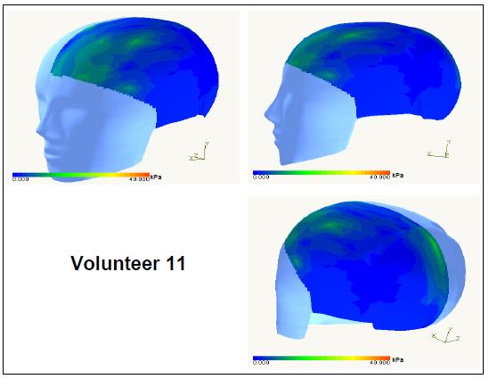
136 126
137 127
138 128
139 129
140 130
141 131
142 132
143 133
144 134
145 135
146 136
147 137
148 138
149 139
150 140
151 141
152 142
153 143
154 144
155 145
156 146
157 147
158 148
159 149
160 150
161 151
162 152

163 153 APPENDIX D HELMET CONCUSSION ASSESSMENT PROGRAM
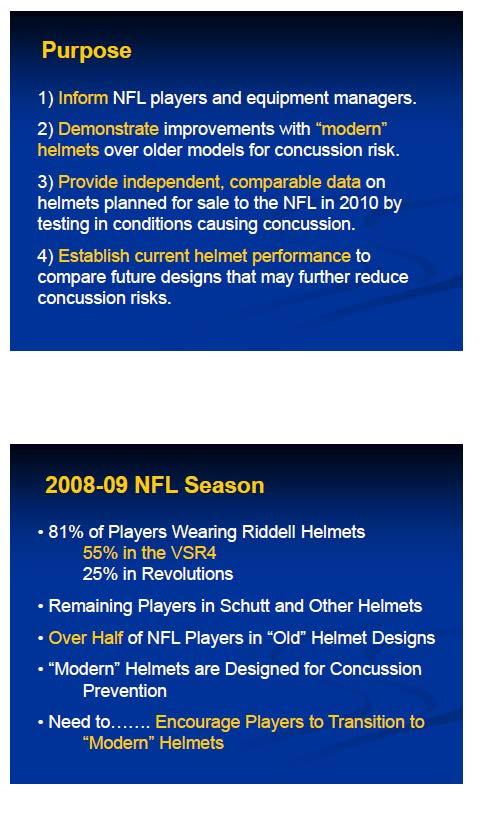
164 154
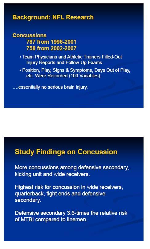
165 155
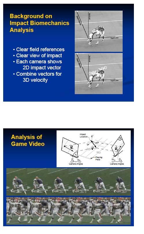
166 156
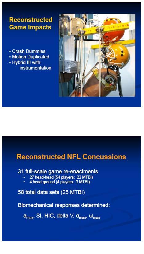
167 157
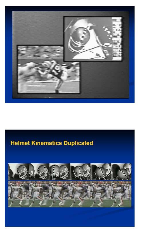
168 158
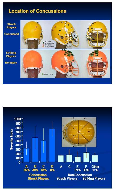
169 159
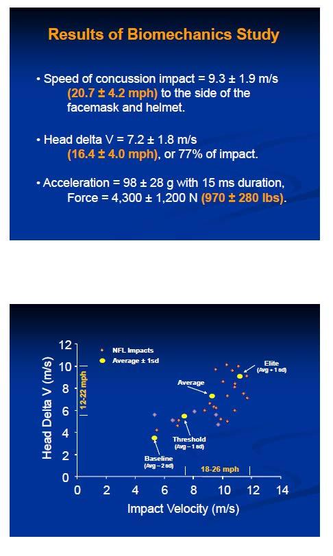
170 160
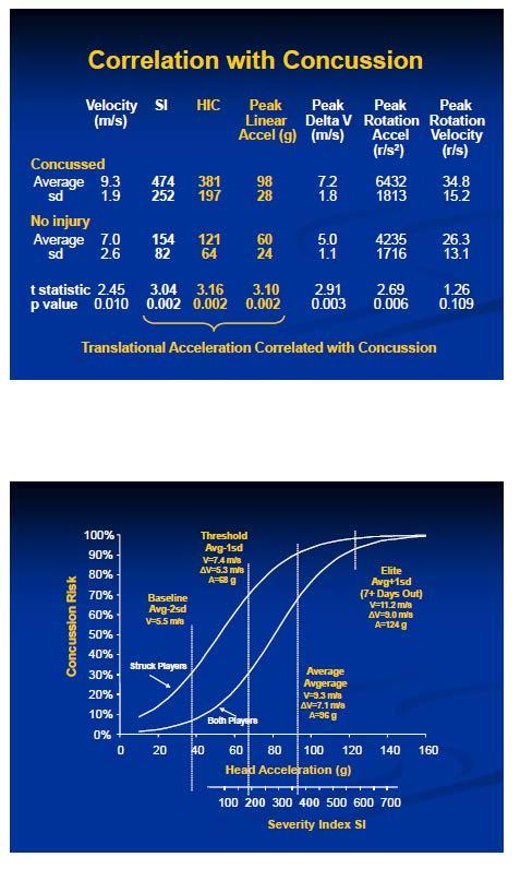
171 161
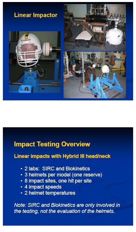
172 162
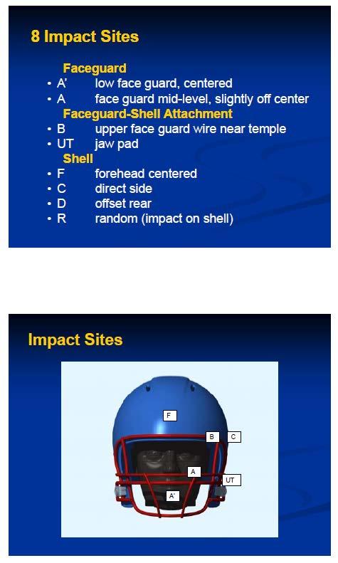
173 163
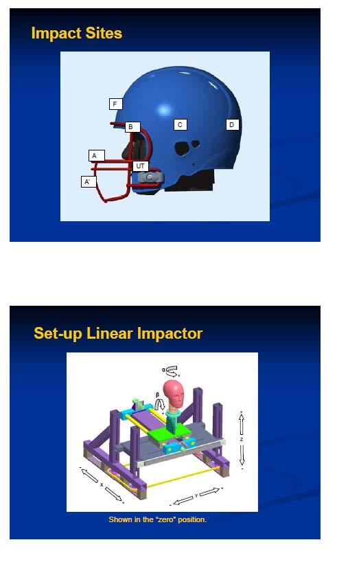
174 164
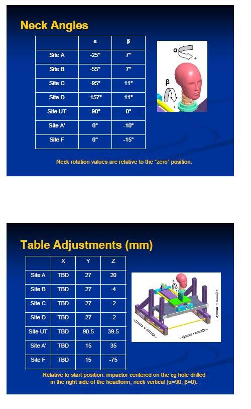
175 165
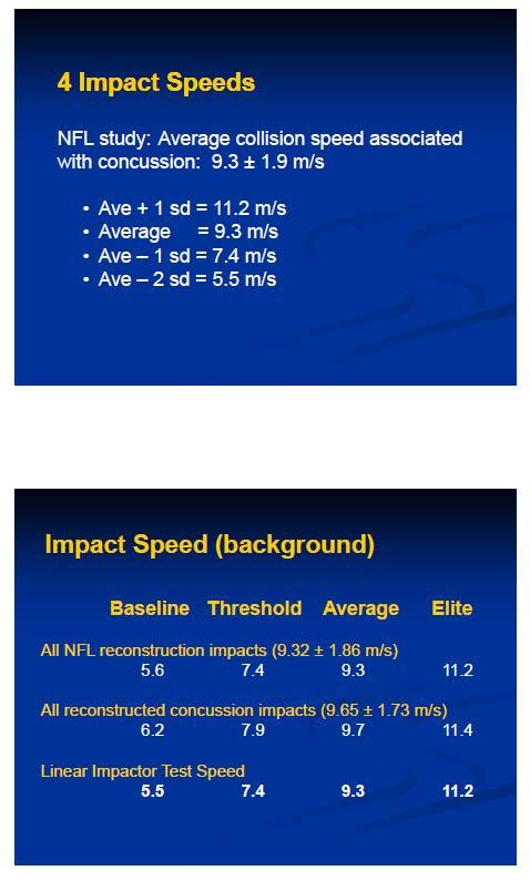
176 166
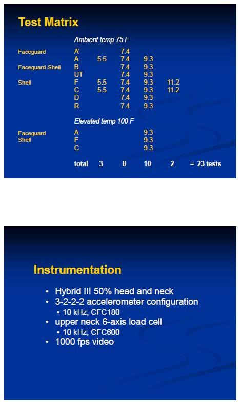
177 167
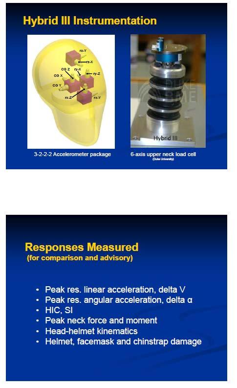
178 168
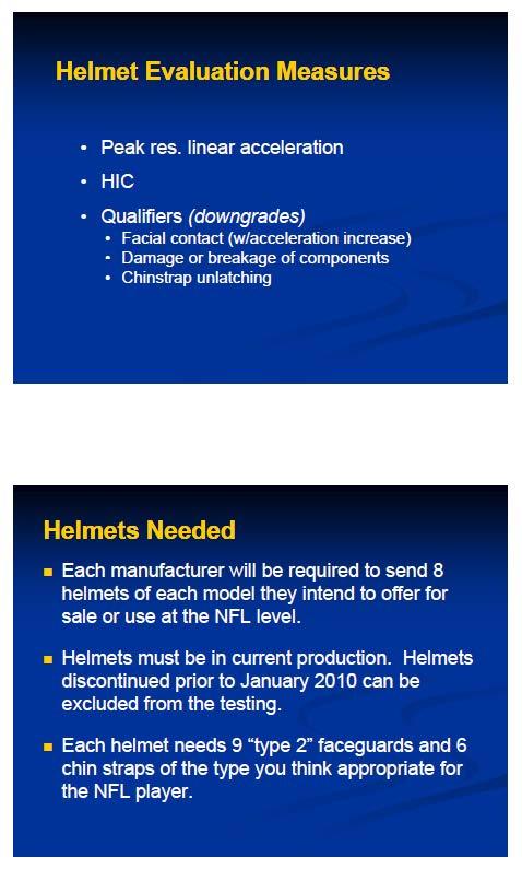
179 169
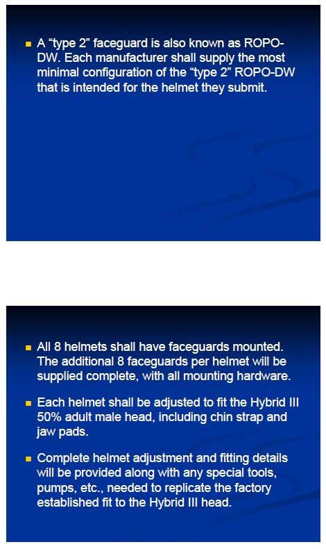
180 170
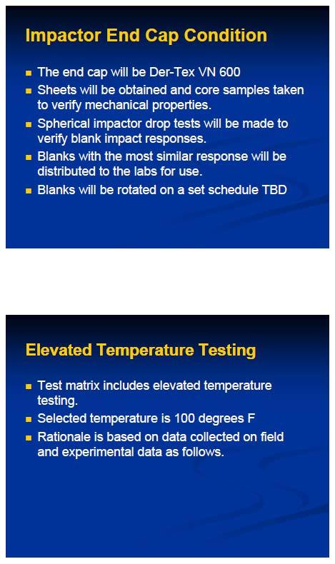
181 171
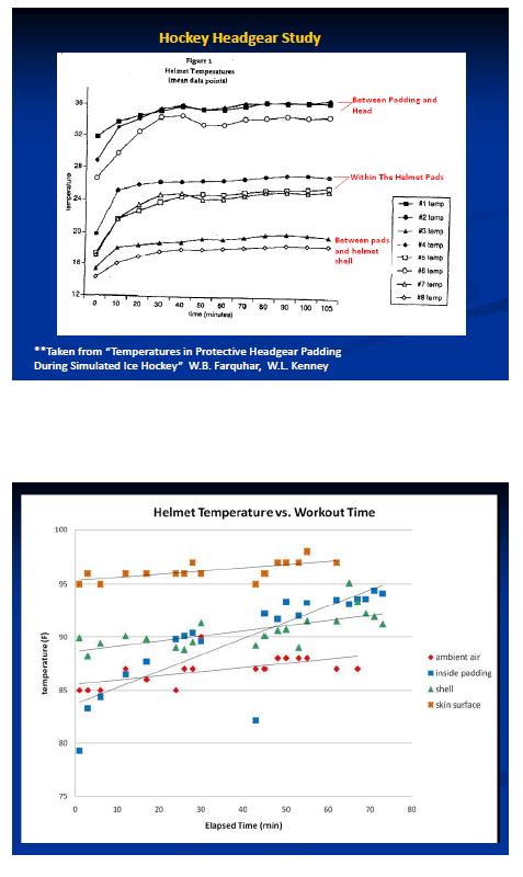
182 172

183 173
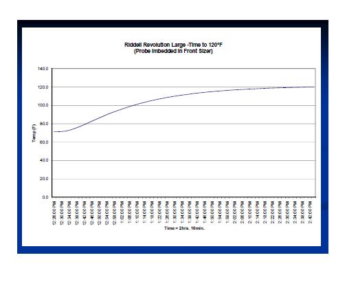
184 174
Summary of Guardian Protective Cover Impact Testing April 5, 2011
 Summary of Protective Cover Impact Testing April 5, 11 Attached is the graphical data and analysis of representative impacts that occurred during testing from our tri-axial accelerometer. We used the DTS
20XX. Bicycle Helmets for Children 2017 tested by Folksam
 20XX Bicycle Helmets for Children 2017 tested by Folksam This is why we test bicycle helmets Every day three cyclists in Sweden sustain head injuries, which are some of the most severe injuries a cyclist
A Method for Assessing the Overall Impact Performance of Riot Helmets
 246 JOURNAL OF APPLIED BIOMECHANICS, 2003, 19, 246-254 2003 by Human Kinetics Publishers, Inc. A Method for Assessing the Overall Impact Performance of Riot Helmets Jean-Philippe Dionne, Ismail El Maach,
Head Impacts in Hockey and Youth Football: Biomechanical Response and Helmet Padding Characteristics. Anna M. MacAlister
 Head Impacts in Hockey and Youth Football: Biomechanical Response and Helmet Padding Characteristics Anna M. MacAlister Thesis submitted to the faculty of the Virginia Polytechnic Institute and State University
Procedia Engineering Procedia Engineering 2 (2010)
") Available online at www.sciencedirect.com Procedia Engineering Procedia Engineering 2 (2010) 002681 2686 (2009) 000 000 Procedia Engineering www.elsevier.com/locate/procedia 8 th Conference of the International
Available online at www.sciencedirect.com Procedia Engineering Procedia Engineering 2 (2010) 002681 2686 (2009) 000 000 Procedia Engineering www.elsevier.com/locate/procedia 8 th Conference of the International
MIL-STD-883G METHOD
 STEADY-STATE LIFE 1. PURPOSE. The steady-state life test is performed for the purpose of demonstrating the quality or reliability of devices subjected to the specified conditions over an extended time
Equation 1: F spring = kx. Where F is the force of the spring, k is the spring constant and x is the displacement of the spring. Equation 2: F = mg
 1 Introduction Relationship between Spring Constant and Length of Bungee Cord In this experiment, we aimed to model the behavior of the bungee cord that will be used in the Bungee Challenge. Specifically,
Quantifying the effect of the facemask on helmet performance
 Original Article Quantifying the effect of the facemask on helmet performance Proc IMechE Part P: J Sports Engineering and Technology 2018, Vol. 232(2) 94 101 Ó IMechE 2017 Reprints and permissions: sagepub.co.uk/journalspermissions.nav
Subject Index. STPIO50-EB/Sep Boot construction and blade fit, 135 Brain injury impact testing and,
 STPIO50-EB/Sep. 1989 Subject Index A Acceleration drop height, multidirectional, 257 helmet impact testing, 244, 248-249 Accelerometer, 270 Adolescent players, physique differences in, 90-93 Aging of equipment,
POWER Quantifying Correction Curve Uncertainty Through Empirical Methods
 Proceedings of the ASME 2014 Power Conference POWER2014 July 28-31, 2014, Baltimore, Maryland, USA POWER2014-32187 Quantifying Correction Curve Uncertainty Through Empirical Methods ABSTRACT Christopher
Linear and Angular Head Acceleration Measurements in Collegiate Football
 Steven Rowson Center for Injury Biomechanics, Virginia Tech-Wake Forest, Blacksburg, VA 24061 Gunnar Brolinson Edward Via Virginia College of Osteopathic Medicine, Blacksburg, VA 24061 Mike Goforth Dave
WHAT IS MIPS? AND HOW DOES IT WORK?
 WHAT IS MIPS? AND HOW DOES IT WORK? In a helmet with MIPS Brain Protection System (BPS) the shell and the liner are separated by a Low Friction Layer. When a helmet with MIPS Brain Protection System is
AC : MEASUREMENT OF HYDROGEN IN HELIUM FLOW
 AC 2010-2145: MEASUREMENT OF HYDROGEN IN HELIUM FLOW Randy Buchanan, University of Southern Mississippi Christopher Winstead, University of Southern Mississippi Anton Netchaev, University of Southern Mississippi
Wind Flow Validation Summary
 IBHS Research Center Validation of Wind Capabilities The Insurance Institute for Business & Home Safety (IBHS) Research Center full-scale test facility provides opportunities to simulate natural wind conditions
REPORT. A comparative study of the mechanical and biomechanical behaviour of natural turf and hybrid turf for the practise of sports
 REPORT A comparative study of the mechanical and biomechanical behaviour of natural turf and hybrid turf for the practise of sports Addressed to: PSF - PALAU TURF Date: May 2015 Table of Contents SHEET
General Accreditation Guidance. User checks and maintenance of laboratory balances
 General Accreditation Guidance User checks and maintenance of laboratory balances January 2018 Copyright National Association of Testing Authorities, Australia 2010 All intellectual property rights in
Analysis of Padding Recovery Time for Sports Helmets
 Analysis of Padding Recovery Time for Sports Helmets Undergraduate Honors Thesis Presented in Partial Fulfillment of the Requirements for Graduation with Research Distinction in the Department of Mechanical
Datalogging Shirt for Baseball Pitchers
 Datalogging Shirt for Baseball Pitchers Design Team Marcus Moché, Alexandra Morgan, David Schmidt Design Advisor Prof. M. Taslim Abstract Baseball pitcher elbow injuries have been increasing in frequency
Exploring the relationship between the pressure of the ball and coefficient of restitution.
 Exploring the relationship between the pressure of the ball and coefficient of restitution. When I started thinking about possible investigations I knew I wanted to create a lab that was related to sports.
Sports-related concussions are a growing public. Biomechanical performance of leather and modern football helmets. Technical note
 See the corresponding editorial in this issue, pp 803 804. J Neurosurg 119:805 809, 2013 AANS, 2013 Biomechanical performance of leather and modern football helmets Technical note Steven Rowson, Ph.D.,
12/6/2017. Evidence-Based Practice: Head Impacts in Lacrosse: Should We Be Concerned? Disclaimer. Concussions in Lacrosse
 Evidence-Based Practice: Head Impacts in Lacrosse: Should We Be Concerned? Fredericksburg Regional Sports Medicine Symposium Michael Higgins PhD, ATC, PT, CSCS University of Virginia Objectives: Following
Gerald D. Anderson. Education Technical Specialist
 Gerald D. Anderson Education Technical Specialist The factors which influence selection of equipment for a liquid level control loop interact significantly. Analyses of these factors and their interactions
These Terms and conditions apply to audit trails incorporated in weighing and measuring devices and systems 1.
 Title: Terms and Conditions for the Approval of Metrological Audit Trails Effective Date: 2006-03-16 Page: 1 of 9 Revision: 1.0 Application These Terms and conditions apply to audit trails incorporated
ITTC Recommended Procedures and Guidelines
 Page 1 of 6 Table of Contents 1. PURPOSE...2 2. PARAMETERS...2 2.1 General Considerations...2 3 DESCRIPTION OF PROCEDURE...2 3.1 Model Design and Construction...2 3.2 Measurements...3 3.5 Execution of
Predicted Dispense Volume vs. Gravimetric Measurement for the MICROLAB 600. November 2010
 Predicted Dispense Volume vs. Gravimetric Measurement for the MICROLAB 600 November 2010 Table of Contents ``Abstract...3 ``Introduction...4 ``Methods & Results...6 ``Data Analysis...9 ``Conclusion...12
CHAPTER 10 TOTAL RECREATIONAL FISHING DAMAGES AND CONCLUSIONS
 CHAPTER 10 TOTAL RECREATIONAL FISHING DAMAGES AND CONCLUSIONS 10.1 INTRODUCTION This chapter provides the computation of the total value of recreational fishing service flow losses (damages) through time
1999 Microcomponents Technology SLYA017A
 Application Brief Number 001 1999 Microcomponents Technology SLYA017A IMPORTANT NOTICE Texas Instruments and its subsidiaries (TI) reserve the right to make changes to their products or to discontinue
The Effect of a Seven Week Exercise Program on Golf Swing Performance and Musculoskeletal Screening Scores
 The Effect of a Seven Week Exercise Program on Golf Swing Performance and Musculoskeletal Screening Scores 2017 Mico Hannes Olivier Bachelor of Sport Science Faculty of Health Sciences and Medicine Bond
GEA FOR ADVANCED STRUCTURAL DYNAMIC ANALYSIS
 SMART SOLUTIONS FOR VIBRATION MONITORING GEA FOR ADVANCED STRUCTURAL DYNAMIC ANALYSIS ANALYSIS OF CIVIL STRUCTURES - EXPO MERLATA PEDESTRIAN BRIDGE ABSTRACT Civil structures and in particular bridges and
TEMPORAL ANALYSIS OF THE JAVELIN THROW
 TEMPORAL ANALYSIS OF THE JAVELIN THROW Derek M. Helenbergerl, Michael T. Sanders 2, and Lawrence D. Abraha~n',~ Biomedical Engineering, Intercollegiate Athletics for Men, Kinesiology & Health Education
Autodesk Moldflow Communicator Process settings
 Autodesk Moldflow Communicator 212 Process settings Revision 1, 3 March 211. Contents Chapter 1 Process settings....................................... 1 Profiles.................................................
EUROPEAN NEW CAR ASSESSMENT PROGRAMME (Euro NCAP) SLED TEST PROCEDURE FOR ASSESSING KNEE IMPACT AREAS
 SLED TEST PROCEDURE FOR ASSESSING KNEE IMPACT AREAS") www.euroncap.com EUROPEAN NEW CAR ASSESSMENT PROGRAMME (Euro NCAP) SLED TEST PROCEDURE FOR ASSESSING KNEE IMPACT AREAS Version 1.0a December 2004 Sled Test Procedure for Assessing Knee Impact Areas (V1.0a)
www.euroncap.com EUROPEAN NEW CAR ASSESSMENT PROGRAMME (Euro NCAP) SLED TEST PROCEDURE FOR ASSESSING KNEE IMPACT AREAS Version 1.0a December 2004 Sled Test Procedure for Assessing Knee Impact Areas (V1.0a)
STANDARD PERFORMANCE SPECIFICATION FOR NEWLY MANUFACTURED BASEBALL/SOFTBALL CATCHER S HELMETS WITH FACEGUARD NOCSAE DOC (ND)
") STANDARD PERFORMANCE SPECIFICATION FOR NEWLY MANUFACTURED BASEBALL/SOFTBALL CATCHER S HELMETS WITH FACEGUARD NOCSAE DOC (ND) 024-18 Prepared By NATIONAL OPERATING COMMITTEE ON STANDARDS FOR ATHLETIC EQUIPMENT
STANDARD PERFORMANCE SPECIFICATION FOR NEWLY MANUFACTURED BASEBALL/SOFTBALL CATCHER S HELMETS WITH FACEGUARD NOCSAE DOC (ND) 024-18 Prepared By NATIONAL OPERATING COMMITTEE ON STANDARDS FOR ATHLETIC EQUIPMENT
STANDARD PERFORMANCE SPECIFICATION FOR NEWLY MANUFACTURED BASEBALL/SOFTBALL CATCHER S HELMETS WITH FACEGUARD. NOCSAE DOC (ND) m14
 m14") STANDARD PERFORMANCE SPECIFICATION FOR NEWLY MANUFACTURED BASEBALL/SOFTBALL CATCHER S HELMETS WITH FACEGUARD NOCSAE DOC (ND) 024-11m14 Prepared By NATIONAL OPERATING COMMITTEE ON STANDARDS FOR ATHLETIC
STANDARD PERFORMANCE SPECIFICATION FOR NEWLY MANUFACTURED BASEBALL/SOFTBALL CATCHER S HELMETS WITH FACEGUARD NOCSAE DOC (ND) 024-11m14 Prepared By NATIONAL OPERATING COMMITTEE ON STANDARDS FOR ATHLETIC
Application Note AN-107
 SPEC Sensor TM Characterization & Calibration Considerations Scope This document is provided to describe the considerations needed to characterize, calibrate, verify and validate the measurement performance
Ground Forces Impact on Release of Rotational Shot Put Technique
 Brigham Young University BYU ScholarsArchive All Theses and Dissertations 2014-12-01 Ground Forces Impact on Release of Rotational Shot Put Technique Niklas B. Arrhenius Brigham Young University - Provo
Biomechanical Forces of Concussions. February 20, 2013 Martin Mrazik, PhD, R.Psych. University of Alberta
 Biomechanical Forces of Concussions February 20, 2013 Martin Mrazik, PhD, R.Psych. University of Alberta Acknowledgements The Problem In the News The Globe and Mail (March 15, 2011): Bob Probert s brain
Applying Hooke s Law to Multiple Bungee Cords. Introduction
 Applying Hooke s Law to Multiple Bungee Cords Introduction Hooke s Law declares that the force exerted on a spring is proportional to the amount of stretch or compression on the spring, is always directed
Ron Gibson, Senior Engineer Gary McCargar, Senior Engineer ONEOK Partners
 New Developments to Improve Natural Gas Custody Transfer Applications with Coriolis Meters Including Application of Multi-Point Piecewise Linear Interpolation (PWL) Marc Buttler, Midstream O&G Marketing
Specific Accreditation Criteria Calibration ISO IEC Annex. Mass and related quantities
 Specific Accreditation Criteria Calibration ISO IEC 17025 Annex Mass and related quantities January 2018 Copyright National Association of Testing Authorities, Australia 2014 This publication is protected
Exploring the relationship between the pressure of the ball and coefficient of restitution.
 Exploring the relationship between the pressure of the ball and coefficient of restitution. When I started thinking about possible investigations I knew I wanted to create a lab that was related to sports.
Protective equipment for use in ice hockey. Part 2: Head protection for skaters
 Provläsningsexemplar / Preview INTERNATIONAL STANDARD ISO 10256-2 First edition 2016-12-01 Protective equipment for use in ice hockey Part 2: Head protection for skaters Équipements de protection destinés
Analysis of Pressure Rise During Internal Arc Faults in Switchgear
 Analysis of Pressure Rise During Internal Arc Faults in Switchgear ASANUMA, Gaku ONCHI, Toshiyuki TOYAMA, Kentaro ABSTRACT Switchgear include devices that play an important role in operations such as electric
STANDARD METHOD OF IMPACT TEST AND PERFORMANCE REQUIREMENTS FOR FOOTBALL FACEGUARDS. NOCSAE DOC ND087-17m17c
 STANDARD METHOD OF IMPACT TEST AND PERFORMANCE REQUIREMENTS FOR FOOTBALL FACEGUARDS NOCSAE DOC ND087-17m17c Prepared by NATIONAL OPERATING COMMITTEE ON STANDARDS FOR ATHLETIC EQUIPMENT Revised: January
AndrewsREF.org 1020 Gulf Breeze Parkway, Gulf Breeze, FL (850)
") The Andrews Research and Education Foundation are proud to present the results of testing on the FaceLoc quick release system that has been completed in conjunction with the sponsoring company. Introduction:
The Andrews Research and Education Foundation are proud to present the results of testing on the FaceLoc quick release system that has been completed in conjunction with the sponsoring company. Introduction:
Queue analysis for the toll station of the Öresund fixed link. Pontus Matstoms *
 Queue analysis for the toll station of the Öresund fixed link Pontus Matstoms * Abstract A new simulation model for queue and capacity analysis of a toll station is presented. The model and its software
Naval Postgraduate School, Operational Oceanography and Meteorology. Since inputs from UDAS are continuously used in projects at the Naval
 How Accurate are UDAS True Winds? Charles L Williams, LT USN September 5, 2006 Naval Postgraduate School, Operational Oceanography and Meteorology Abstract Since inputs from UDAS are continuously used
FIM RACING HOMOLOGATION PROGRAMME FOR HELMETS (FRHPhe) Extract of the Homologation Manual n. FRHPhe-01
 Extract of the Homologation Manual n. FRHPhe-01") FIM RACING HOMOLOGATION PROGRAMME FOR HELMETS (FRHPhe) Extract of the Homologation Manual n. FRHPhe-01 October 2017 GLOSSARY... 3 FOREWORD... 4 SCOPE... 6 TECHNICAL INFORMATION AND CRITERIA (FIM HELMET
FIM RACING HOMOLOGATION PROGRAMME FOR HELMETS (FRHPhe) Extract of the Homologation Manual n. FRHPhe-01 October 2017 GLOSSARY... 3 FOREWORD... 4 SCOPE... 6 TECHNICAL INFORMATION AND CRITERIA (FIM HELMET
Presented to the International Technical Rescue Symposium, November Abstract
 Presented to the International Technical Rescue Symposium, November 21 Presented by: Chuck Weber, PMI Quality Manager Abstract This paper presents the results of 162 individual drop tests performed at
Design of a Microcontroller-Based Pitch Angle Controller for a Wind Powered Generator
 Journal of Engineering and Science Research 1 (2): 133-138, e-issn RMP Publications, DOI: Design of a Microcontroller-Based Pitch Angle Controller for a Wind Powered Generator Glenn V. Magwili, Michael
Smart Water Application Technologies (SWAT)
") Smart Water Application Technologies (SWAT) Turf and Landscape Irrigation Equipment PRESSURE REGULATING SPRAY HEAD SPRINKLERS Equipment Functionality Test Testing Protocol Version 3.0 (May 2012) Developed
Smart Water Application Technologies (SWAT) Turf and Landscape Irrigation Equipment PRESSURE REGULATING SPRAY HEAD SPRINKLERS Equipment Functionality Test Testing Protocol Version 3.0 (May 2012) Developed
Final Report for Measurement of Head Velocities of Boxing Participants. with Wireless Digital Accelerometers. Daniel Bullock
 A. Title Page Final Report for Measurement of Head Velocities of Boxing Participants with Wireless Digital Accelerometers Daniel Bullock Associate Professor of Electrical Engineering and Physics Corley
3. REQUIRED EQUIPMENT
 TEC? 700-700 Materiel Test Procedure 5-2-540 White Sands Missile Range I. OBJECTIVE U. S. ARMY TEST AND EVALUATION COMMAND COMMON ENGINEERING TEST PROCEDURE MISSILEBORNE GAS OPERATED POWER SUPPLY TESTS
The Effect of Play Type and Collision Closing Distance on Head Impact Biomechanics. Karen Elaine Ocwieja
 The Effect of Play Type and Collision Closing Distance on Head Impact Biomechanics Karen Elaine Ocwieja A thesis submitted to the faculty of the University of North Carolina at Chapel Hill in partial fulfillment
A hose layline contains important information for specifying the replacement assembly: manufacturer, hose trade name, working pressure and hose ID.
 CONTENTS Introduction Pressure Pressure Drop Temperature Rating Bend Radius Conclusion Additional Information SIDEBAR: Understanding Hydraulic Hose Reinforcement INTRODUCTION Hydraulic hose has a finite
Latest FE Model Development of THOR-50M Crash Test Dummy
 Latest FE Model Development of THOR-50M Crash Test Dummy Ismail Maatouki*, Stephen Fu**, Zaifei Zhou**, *Humanetics Europe GmbH, Heidelberg, Germany **Humanetics Innovative Solutions, Inc. Farmington Hills,
AI TKA '[ Attorney Docket No Date: 28 June 2007
 AI TKA '[ DEPARTMENT OF THE NAVY NAVAL UNDERSEA WARFARE CENTER DPVSION NEWPORT OFFICE OF COUNSEL PHONE: (401) 832-3653 FAX: (401) 832-4432 NEWPORT DSN: 432-3653 Attorney Docket No. 84854 Date: 28 June
intended velocity ( u k arm movements
 Fig. A Complete Brain-Machine Interface B Human Subjects Closed-Loop Simulator ensemble action potentials (n k ) ensemble action potentials (n k ) primary motor cortex simulated primary motor cortex neuroprosthetic
Analysis of Shear Lag in Steel Angle Connectors
 University of New Hampshire University of New Hampshire Scholars' Repository Honors Theses and Capstones Student Scholarship Spring 2013 Analysis of Shear Lag in Steel Angle Connectors Benjamin Sawyer
METHOD 25A - DETERMINATION OF TOTAL GASEOUS ORGANIC CONCENTRATION USING A FLAME IONIZATION ANALYZER
 1250 METHOD 25A - DETERMINATION OF TOTAL GASEOUS ORGANIC CONCENTRATION USING A FLAME IONIZATION ANALYZER 1.0 Scope and Application. 1.1 Analytes. Analyte CAS No. Sensitivity Total Organic Compounds N/A
Analysis of Traditional Yaw Measurements
 Analysis of Traditional Yaw Measurements Curiosity is the very basis of education and if you tell me that curiosity killed the cat, I say only the cat died nobly. Arnold Edinborough Limitations of Post-
ROSE-HULMAN INSTITUTE OF TECHNOLOGY Department of Mechanical Engineering. Mini-project 3 Tennis ball launcher
 Mini-project 3 Tennis ball launcher Mini-Project 3 requires you to use MATLAB to model the trajectory of a tennis ball being shot from a tennis ball launcher to a player. The tennis ball trajectory model
Certification of AMS acc. EN 15267, Part 3 - Overview and First Experience -
 Certification of AMS acc. EN 15267, Part 3 - Overview and First Experience - Dr. Wolfgang Jockel, Martin Schneider, TÜV Rheinland Group, D-51105 Cologne / Germany 1. Introduction A new basis for the certification
TEST FOR STABILOMETER VALUE OF BITUMINOUS MIXTURES
 Test Procedure for TEST FOR STABILOMETER VALUE OF BITUMINOUS MIXTURES TxDOT Designation: Tex-208-F Effective Date: February 2005 1. SCOPE 1.1 Use this test method to determine the Hveem stability value
Evaluating the Influence of R3 Treatments on Fishing License Sales in Pennsylvania
 Evaluating the Influence of R3 Treatments on Fishing License Sales in Pennsylvania Prepared for the: Pennsylvania Fish and Boat Commission Produced by: PO Box 6435 Fernandina Beach, FL 32035 Tel (904)
Snowsport Helmets: The Good and Bad
 Snowsport Helmets: The Good and Bad Irving Scher, PhD, PE Jasper Shealy, PhD Inherent Risks in Snow Sports Head Injuries in Snow Sports 4% to 12% of all injuries Potential outcomes: minor to severe Death
Prevention Of Accidents Caused By Rotating Transit Bus Wheels By James M. Green, P.E., DEE
 Prevention Of Accidents Caused By Rotating Transit Bus Wheels By James M. Green, P.E., DEE Introduction The accident statistics for injuries caused by pedestrians or cyclists being injured, or killed,
Ozobot Bit Classroom Application: Boyle s Law Simulation
 OZO AP P EAM TR T S BO RO VE D Ozobot Bit Classroom Application: Boyle s Law Simulation Created by Richard Born Associate Professor Emeritus Northern Illinois University richb@rborn.org Topics Chemistry,
Pressure Sensor Bridge Configurations
 Pressure Sensor Bridge Configurations 1. Purpose Describe different pressure sensor bridge configurations, when each can and cannot be used, and the advantages and disadvantages of each. 2. Introduction
DEPARTMENT OF THE NAVY DIVISION NEWPORT OFFICE OF COUNSEL PHONE: FAX: DSN:
 IMAVSBA WARFARE CENTERS NEWPORT DEPARTMENT OF THE NAVY NAVAL UNDERSEA WARFARE CENTER DIVISION NEWPORT OFFICE OF COUNSEL PHONE: 401 832-3653 FAX: 401 832-4432 DSN: 432-3653 Attorney Docket No. 85031 Date:
AMS 6916 Board mount pressure sensor with ratiometric analog output
 FEATURES Piezoresistive pressure sensor with amplified analog output Calibrated and temperature compensated Ratiometric voltage output, 0.5 4.5 V Digital signal conditioning, 12 bit output resolution Differential,
AN31E Application Note
 Balancing Theory Aim of balancing How an unbalance evolves An unbalance exists when the principle mass axis of a rotating body, the so-called axis of inertia, does not coincide with the rotational axis.
DESIGN OPTIMIZATION OF WORK ROLL CHOCK AND BACKUP ROLL CHOCK IN COLD ROLLING MILL
 DESIGN OPTIMIZATION OF WORK ROLL CHOCK AND BACKUP ROLL CHOCK IN COLD ROLLING MILL Tukesh Sahu 1, Prof. G.R.Kesheory 2 1M.Tech Scholar, Department of Mechanical Engineering, VITS Indore, MP, India 2Assistant
Earmuff Comfort Evaluation
 Earmuff Comfort Evaluation Rafael GERGES 1 ; Samir GERGES 1,2 1 Federal university of Santa Catarina (UFSC)/EMC, Brazil 2 Institute Federal de Santa Catarina (IFSC)/Mecatronic, Brazil ABSTRACT The use
Project Number: P14474
 Multidisciplinary Senior Design Conference Kate Gleason College of Engineering Rochester Institute of Technology Rochester, New York 14623 Project Number: P14474 HYDROSTATIC TEST APPARATUS Anushka Kalicharan
EXPERIMENTAL RESULTS OF GUIDED WAVE TRAVEL TIME TOMOGRAPHY
 18 th World Conference on Non destructive Testing, 16-20 April 2012, Durban, South Africa EXPERIMENTAL RESULTS OF GUIDED WAVE TRAVEL TIME TOMOGRAPHY Arno VOLKER 1 and Hendrik VOS 1 TNO, Stieltjesweg 1,
Study conducted by University of North Carolina Department of Exercise and Sports Science,
 THE LEARNING CURVE Little League Seeks to Address Concerns, Answer Questions about Curveballs & Overuse Study conducted by University of North Carolina Department of Exercise and Sports Science, Table
UNIVERSITY OF WATERLOO
 UNIVERSITY OF WATERLOO Department of Chemical Engineering ChE 524 Process Control Laboratory Instruction Manual January, 2001 Revised: May, 2009 1 Experiment # 2 - Double Pipe Heat Exchanger Experimental
Stress evaluation of a bicycle crank arm connection using BEM
 Stress evaluation of a bicycle crank arm connection using BEM C. J. Hoff, R. E. Dippery & 3. Knapp Department of Mechanical Engineering Kettering University, USA Abstract An interesting problem encountered
2600T Series Pressure Transmitters Plugged Impulse Line Detection Diagnostic. Pressure Measurement Engineered solutions for all applications
 Application Description AG/266PILD-EN Rev. C 2600T Series Pressure Transmitters Plugged Impulse Line Detection Diagnostic Pressure Measurement Engineered solutions for all applications Increase plant productivity
CFD Simulation and Experimental Validation of a Diaphragm Pressure Wave Generator
 CFD Simulation and Experimental Validation of a Diaphragm Pressure Wave Generator T. Huang 1, A. Caughley 2, R. Young 2 and V. Chamritski 1 1 HTS-110 Ltd Lower Hutt, New Zealand 2 Industrial Research Ltd
MODEL WEIGH MODULE
 MODEL 65082 WEIGH MODULE INSTALLATION & OPERATING MANUAL P.O. Box 775 - Farmington, NH 03835 Tel: 603-755-3885 email: cands_nh@msn.com www.candscontrols.com Model 65023 Cantilever Beam Transducer Nickel-Plated
Discussion and guidance on the definition and qualification of porous loads
 SUMMARY Porous Loads requiring Sterilisation are often a Critical Control Point for the manufacture of Sterile products. Particularly Aseptically filled products. Regulatory guidance in this area is not
7 th International Conference on Wind Turbine Noise Rotterdam 2 nd to 5 th May 2017
 7 th International Conference on Wind Turbine Noise Rotterdam 2 nd to 5 th May 2017 Sound power level measurements 3.0 ir. L.M. Eilders, Peutz bv: l.eilders@peutz.nl ing. E.H.A. de Beer, Peutz bv: e.debeer@peutz.nl
Cover Page for Lab Report Group Portion. Pump Performance
 Cover Page for Lab Report Group Portion Pump Performance Prepared by Professor J. M. Cimbala, Penn State University Latest revision: 02 March 2012 Name 1: Name 2: Name 3: [Name 4: ] Date: Section number:
Title: Standard Operating Procedure for R&R Environmental Devices Model MFC201 Gas Dilution Calibrator
 Procedure No: SOP-029 Revision No: 1.1 (December 29, 2010) Page No.: 1 of 7 1. INTRODUCTION AND SCOPE To obtain timely data for the purpose of air quality assessment, air quality trend reporting, air quality
HOCKEY HELMET TEST RESULTS
 ESPN.com: OTL [Print without images] Thursday, March 26, 2015 Updated: March 30, 2:10 PM ET Study: Many hockey helmets unsafe By Steve Fainaru ESPN.com More than a quarter of all helmets worn by hockey
DX2/DXX Operating Instructions
 CHECK LINE BY ELECTROMATIC DX2/DXX Operating Instructions CHECK LINE INSTRUMENTS ELECTROMATIC E Q U I P M E N T C O., I N C. 600 Oakland Ave., Cedarhurst, NY 11516 U.S.A. TEL: 516-295-4300 FAX: 516-295-4399
Limb Perfusion Device
 1 Limb Perfusion Device Design Team Peter Colby, Eric Greenberg, Nicholas Soo Hoo, Keith Travis Design Advisor Prof. Jeffrey Ruberti Abstract Every year thousands of people lose part or all of their upper
Offshore platforms survivability to underwater explosions: part I
 Computational Ballistics III 123 Offshore platforms survivability to underwater explosions: part I A. A. Motta 1, E. A. P. Silva 2, N. F. F. Ebecken 2 & T. A. Netto 2 1 Brazilian Navy Research Institute,
Exercise 3. Power Versus Wind Speed EXERCISE OBJECTIVE DISCUSSION OUTLINE. Air density DISCUSSION
 Exercise 3 Power Versus Wind Speed EXERCISE OBJECTIVE When you have completed this exercise, you will know how to calculate the power contained in the wind, and how wind power varies with wind speed. You
What standards apply to rooftop fall protections systems?
 What standards apply to rooftop fall protections systems? For a number of years, the standards governing the design, installation, use and inspection of fixed fall protection systems have been vague at
ISOLATION OF NON-HYDROSTATIC REGIONS WITHIN A BASIN
 ISOLATION OF NON-HYDROSTATIC REGIONS WITHIN A BASIN Bridget M. Wadzuk 1 (Member, ASCE) and Ben R. Hodges 2 (Member, ASCE) ABSTRACT Modeling of dynamic pressure appears necessary to achieve a more robust
23 RD INTERNATIONAL SYMPOSIUM ON BALLISTICS TARRAGONA, SPAIN APRIL 2007
 23 RD INTERNATIONAL SYMPOSIUM ON BALLISTICS TARRAGONA, SPAIN 16-20 APRIL 2007 AN INVESTIGATION INTO THE INTERRELATION BETWEEN THE INTERNAL AND EXTERNAL BALLISTICS OF FIRING A TP-T TANK AMMUNITION M. H.
Downloaded from SAE International by Universiti Teknologi Malaysia, Monday, October 05, 2015
 2005-01-3941 SAE TECHNICAL PAPER SERIES Brake Pad Surface Topography Part I: Contact Pressure Distribution Abd Rahim Abu Bakar and Huajiang Ouyang University of Liverpool Jennifer E. Siegel Sensor Products
Wave Motion. interference destructive interferecne constructive interference in phase. out of phase standing wave antinodes resonant frequencies
 Wave Motion Vocabulary mechanical waves pulse continuous periodic wave amplitude period wavelength period wave velocity phase transverse wave longitudinal wave intensity displacement amplitude phase velocity
Design and Analysis of Pressure Safety Release Valve by using Finite Element Analysis
 Design and Analysis of Pressure Safety Release Valve by using Finite Element Analysis Mr.V.D.Rathod* 1, Prof.G.A.Kadam* 2, Mr.V. G. Patil* 3 * 1 M.E. Design (Pursuing), SKN Sinhgad Institute of Technology&
CHAPTER 5: VACUUM TEST WITH VERTICAL DRAINS
 CHAPTER 5: VACUUM TEST WITH VERTICAL DRAINS 5.1 Introduction Using surcharging as the sole soil consolidation mean can take a long time to reach the desired soil settlement. Soil consolidation using prefabricated
CHAPTER 1 ORGANIZATION OF DATA SETS
 CHAPTER 1 ORGANIZATION OF DATA SETS When you collect data, it comes to you in more or less a random fashion and unorganized. For example, what if you gave a 35 item test to a class of 50 students and collect
U.S. CONSUMER PRODUCT SAFETY COMMISSION Office of Compliance
 U.S. CONSUMER PRODUCT SAFETY COMMISSION Office of Compliance Requirements for Bicycle Helmets 16 C.F.R. Part 1203 What is the purpose of the requirements for bicycle helmets? This regulation sets performance