Evaluation of LS-DYNA Corpuscular Particle Method for Side Impact Airbag Deployment Applications
|
|
|
- Philip Chambers
- 5 years ago
- Views:
Transcription
1 13 th International LS-DYNA Users Conference Session: Fluid Structure Interaction Evaluation of LS-DYNA Corpuscular Particle Method for Side Impact Airbag Deployment Applications Chin-Hsu Lin, Yi-Pen Cheng General Motors Jason Wang LSTC ABSTRACT A uniform pressure method, i.e. no pressure variation on bag surface and location, in LS-DYNA has been commonly used to simulate airbag deployment and interaction of airbag with the occupants. Another newly developed LS-DYNA CPM (Corpuscular Particle Methodology) has gained recognition and acceptance recently because it considers the effect of transient gas dynamics and thermodynamics by using a particle to represent a set of air or gas molecules and then a set of particles to represent the entire air or gas molecule in the space of interest. This innovative method, however, has yet be fully utilized and applied with confidence in airbag deployments simulation without systematic tests and validations to avoid non-physical tuning factors traditionally being applied to the uniform pressure airbag finite element models. In this paper, inflator closed and vented tank tests, static airbag deployment test, and linear impactor tests with various configurations and impact speeds are systemically conducted and then correlated with a CPM airbag model to determine whether the methodology can be applied for all the tests and whether any tuning factors should be applied in the process. This innovative LS-DYNA particle method has been fully investigated in this systematic study by correlating it with a comprehensive set of inflator tank tests, static airbag deployment, and rigid linear impactor tests. The correlations start from inflator closed and vented tank tests to verify the provided inflator characteristics, mass flow rate and temperature curves. The inflator characteristics will then be employed into static airbag deployment simulation to determine the airbag fabric heat convection coefficient, which is adjusted in this simulation to match the test pressure profile. This is the only parameter tuned to match the test pressure. This airbag model is then used to simulate those linear impact tests. With the systematic validations and correlations to avoid using tuning factors, the airbag model results in a good match of the overall airbag internal pressure and impactor deceleration histories with the tests and the simulations for all the linear impactor tests conducted. Effects of the inflator variations are also studied to illustrate the potential bounds of deceleration and airbag chamber pressure in impacts. INTRODUCTION Control volume (CV) method in LS-DYNA has been widely adopted as the method to simulate airbag deployment for the impact conditions when the airbags have already fully inflated and are in position before the occupant comes into contact with it [1, 2]. For out-of-position (OOP) airbag simulations [3], however, the CV has been recognized as less effective in duplicating the occupant-to-airbag interaction with fidelity. To enhance the airbag deployment and occupant interaction performance, a CPU intense ALE (Arbitrary Lagrangian Eulerian) [4] method has also been developed to address the issues. In recent years, an innovative numerical corpuscular particle methodology has gained more recognition and acceptance for airbag deployment applications [2, 3, 4, 5, 6, 7]. The particle method considers the effect of transient gas dynamics and thermodynamics by using a particle to represent a set of finite air or gas molecules. Then, a set of particles is used to embody all of the air or gas molecules in the space of interest [2]. This particle method, which has slightly higher CPU usage has been documented [2] as an improvement of accuracy over the CV method. In addition, the particle method has a similar accuracy when comparing with the ALE 1-1
2 Session: Fluid Structure Interaction 13 th International LS-DYNA Users Conference method, but it requires significantly less CPU resource. Side impact airbag (SIAB) and passenger side airbag (PAB) are two typical cases that occupants may come into contact with an airbag while it is inflating. In the case of side impact airbag, it can be easily understood since the airbag mounted on the seat side panel is so close to the occupant and its surrounding structure. For the PAB, a similar situation happens when the H3-05 female dummy is in full forward seating position or when a child dummy is tested according to NHTSA out-of-position procedure. There are numerical enhancements with the new LS-DYNA releases, and we need to understand the implication of the changes and their impacts on the correlation and modeling approach. For example, while applying the particle method in airbag simulations, there was an issue of underestimating the mass flow rate through the vent holes when using previous versions of LS-DYNA. The new LS-DYNA offered an enhancement to correctly capture the leakage through the vents, and it will be studied and validated in this project. In order to apply the CPM with confidence to the finite element model, this project was formed and executed. The project approach was, first, to have the supplier conduct the designed inflator tank test, airbag static deployment, and airbag linear impactor tests. The supplier provided CV airbag model and was converted into a CPM model. This CPM model was then used to simulate the static deployment and impact tests according to the test setup. Thoroughly selected model parameters were carefully studied and the heat convection coefficient is tuned within the documented engineering standard ranges to achieve good correlations. To characterize the inflator and generate the required inflator mass flow rate and temperature curves for finite element simulation [8], the inflator closed tank test was conducted by the supplier. After receiving these inflator FE curves, both closed and vented tank tests were simulated using LS-DYNA particle method to ensure fidelity of the inflator model. While calculating the mass flow rate and temperature curves from a conducted inflator closed tank test, the heat loss through conduction with the steel tank surface should be included so that the inflator mass flow rate and temperature curves can be used to reproduce and capture the characteristics seen in the test. Since these two fundamental tank tests were conducted without the complication of airbag deployment, the calculated inflator mass flow rate and temperature curves should be continued to be employed in the subsequent airbag deployment simulations. The airbag deployment correlations are to be conducted after confirmation of the inflator model from the inflator tank test pressure correlations. We start with correlating the static deployment bag pressure history and from it we could determine what are the proper fabric heat convection coefficient, fabric leakage parameter, or the gas leakage through the seam. Then, the linear impact tests with various speeds and configuration will be correlated with the heat convection coefficient and leakage parameters derived from the static deployment test. Those parameters should be identical or very similar when applying the CV method to correlate the pressure or deceleration histories so that they all have the same physical characteristics behind all the parameters. The pressure data from the airbag tests may not be able to represent the average bag pressure in the initial deployment stage, however, the pressure data should be close to the average bag pressure after passing the initial inflating phase. 1-2 After the static deployment correlation, the linear impact tests can then be simulated and


3 13 th International LS-DYNA Users Conference Session: Fluid Structure Interaction correlated and further adjustment of the leakage parameters in LS-DYNA may be necessary to have the subsequent tests well correlated. It is critical to design multiple speeds impact tests or tests with various configurations of impactor orientation relative to the airbag so that the airbag model is robust for various impact conditions. TEST SETUP To reduce the inflator characteristic variation, the vehicle side impact airbag inflators studied in this project are secured from the same manufacturing lot. Two repeated tests are requested for the closed and vented tank tests. Numerous linear impactor tests are conducted and the linear impactor speed, mass, and orientation are allowed to be varied to test the robustness of the airbag modeling. The linear impactor test setups are shown in Figure 1 with different viewing angles. The impactor is also oriented in two directions; one of the airbag body s primary axis is parallel to the impact surface s primary axis so that the entire impactor surface will compress the airbag. The other airbag body primary axis is perpendicular to the impact surface s primary axis so that the impactor surface will compress only a portion of the airbag, as shown in Figure 2. (a) Side view (b) Top view (C) Iso view Figure 1. The linear impactor test set up. The side impact airbag is tested without the plastic housing. (a) side view, (b) top view, (c) isometric view 1-3
 impactor parallel to airbag, (b) impactor perpendicular to airbag TANK TESTS We started with correlating the one cubic foot tank test pressure")
4 Session: Fluid Structure Interaction 13 th International LS-DYNA Users Conference (a) Impactor parallel to airbag (b) Impactor perpendicular to airbag Figure 2. Impactor orientation relative to deployed airbag, (a) impactor parallel to airbag, (b) impactor perpendicular to airbag TANK TESTS We started with correlating the one cubic foot tank test pressure using the mass flow rate and temperature curves of the inflator provided by the supplier in the finite element model. As a standard procedure, the inflator closed tank test is conducted and the pressure is measured to generate an inflator s temperature and mass flow rate curves. The mass flow rate and temperature curves provided can match the peak pressure in a tank test well. However, the pressure after reaching the peak will not decrease gradually as shown in the test in Figure 3. To further improve the pressure correlation, the heat loss through the steel surface is also incorporated in the simulation, and good pressure correlations are achieved, as shown in Figure 3. This selected heat conduction coefficient used in the tank test is a compromise, and it will cause more reduction of the pressure in the closed tank test simulation and less reduction of the pressure in the vented tank test simulation, as shown in Figure 3. The averaged gas temperature inside the tank cannot be accurately obtained since there is a time delay in using devices for measuring the temperature unless a very expensive high speed infrared method is used, therefore the temperature of the test is not available for comparison. In simulating the tank tests pressure, both the particle and CV methods are used to evaluate the methods in duplicating the pressure histories. When using the particle method for closed tank test, the number of particle can be relatively small (10k particles will be fine for such a purpose), and it has little influence on the pressure correlation since the particles will not leak out of the container. There are initial air molecules inside the tank, and they need to be included in the simulation to accurately represent the existing molecules. The rule of thumb in determining the number of particles in the air and gas is to obtain the ratio of the total mass of the air and gas and then formulate the mass of mole of each gas and air particle to be equal. Original kinetic molecular theory is using rigid sphere to represent each molecule. LS-DYNA is using the lumped system and each particle should hold the same amount of molecule (mole) to match the original assumption. For this side impact inflator, the initial air mass inside the one cubic foot tank is about 5 times of the inflator gas. Accordingly, the number of air particles in the tank is devised to be about 5 times of the gas particle. For the vented tank test, the number of particle for the gas is set to be 200k and the air 1-4
 Closed tank test (b) Vented tank test Figure 3.")
5 13 th International LS-DYNA Users Conference Session: Fluid Structure Interaction particle is set to be 1M for this simulation. A larger number of particles will lower the peak pressure slightly in the vented tank test with a higher CPU usage. (a) Closed tank test (b) Vented tank test Figure 3. Tests of closed and vented tank tests and results from finite element simulations using both CV and particle methods. (a) closed tank test, (b) vented tank test. AIRBAG STATIC DEPLOYMENT The LS-DYNA particle airbag method requires that the inflator nozzle FE meshes are enclosed by an airbag cushion throughout the analysis. Since the inflator nozzle was not meshed in the original supplier SIAB model, it needs to be created and placed inside the cushion before running analysis for gas particles to flow into the bag. The FE mesh of the inflator module is not required for CV method. The validated inflator mass flow rate and temperature curves from the tank test are incorporated into the airbag model without using any scaling factors. Since the side impact airbag cushion is made of a coated fabric with sealed seams, which cannot leak gas, the leakage through the fabric modeled in the supplier original CV model is taken out as well. The LS-DYNA *airbag_particle model parameter of BLOCK on vent is set to be 10 so that the gas cannot leak out when the vent is blocked in the deployment process. The heat convention coefficient of the fabric is optimized such that the simulated static deployment pressure history matches the test. Because of the nature of the CV method, the *airbag_hybrid airbag is observed to bounce more when inflated and it can also be observed when comparing the two airbag volume histories, as shown in Figure 4. The CV method also tends to have larger volume and lower pressure in the inflating phase as well. The pressure history is shown in Figure 5 when the heat loss through the fabric was not considered. In order to match the pressure history without the heat loss, some nonphysical tuning factors like additional venting or temperature scaling have been used to compensate to match the test results. The airbag model with this type of tuning can match a single validation impact test, but it is not capable of predicting other impact conditions with confidence. Without the non-physical tuning factors, the CV method can still match the static deployment pressure profile, as shown in Figure 6. Although both methods can correlate the pressure profile reasonably well, the particle method does correlate better when comparing the deployment bag shape with the CV method, as shown in Figure
 airbag volume (c) mass flow out of airbag Figure")
 airbag volume in two simulations, (c) gas")

6 Session: Fluid Structure Interaction 13 th International LS-DYNA Users Conference (a) airbag pressure test vs analysis (b) airbag volume (c) mass flow out of airbag Figure 4. Static deployment correlation of the single chamber side impact airbag, (a) airbag pressure of simulations and tests, (a) airbag volume in two simulations, (c) gas leaking out of airbag for the two methods. Figure 5. Static deployment of side impact airbag using particle method with and without considering the heat loss through fabric. 1-6

 Airbag deployment first 10ms sequence by using *airbag_hybrid method (b) Airbag deployment first 10ms sequence by using *airbag_particle method (c) Comparison of airbag")
7 13 th International LS-DYNA Users Conference Session: Fluid Structure Interaction Figure 6. The static deployment airbag pressure profile using the airbag model delivered from a supplier and new airbag model after stripping off temperature scaling factor and other tuning factors. (a) Airbag deployment first 10ms sequence by using *airbag_hybrid method (b) Airbag deployment first 10ms sequence by using *airbag_particle method (c) Comparison of airbag deployment sequence of particle method and test Figure 7. Static deployment shape of the single chamber SIAB. (a) deployment sequence using CV method, (b) deployment sequence using particle method, (c) comparison of sequence of particle method airbag deployment and test 1-7


8 Session: Fluid Structure Interaction 13 th International LS-DYNA Users Conference LINEAR IMPACTOR TESTS After achieving good static deployment correlation, we then proceed to simulate the first series of two tests and are able to correlate the deceleration pulses and bag pressures as shown in Figures 8 and 9. Initially, there are some reservations of the tests validity because of the very different deceleration profiles among the two tests when their impact speeds were not significantly different. However, the model is able to match the two tests well. Figures 8 and 9 show the results of using the CV and particle methods without tuning factors, and all of the impact tests correlation are shown in Appendix A. The number of particles used in the particle method simulations can influence the accuracy of the results. The default NP (number of particle) listed in the manual is 200k, while in other publication, it was suggested to use 10k particles per liter of volume so that the mean free path or average distance between collisions is roughly 1cm. For this side impact airbag design of 18 liters, the default value in the manual seems to be a good starting point. For this model, however, 800k particles seem to improve the deceleration profile slightly, as shown in Figure 10. (a) Linear impactor deceleration (b) Pressure history Figure 8. Impactor deceleration pulse and airbag pressure histories for 18.2kg impactor with 5.9m/s speed and 60mm distance from the airbag mounting plate to the reaction surface. (a) linear impactor deceleration, (b) pressure history. (a) Linear impactor deceleration (b) Pressure history Figure 9. Impactor deceleration pulse and airbag pressure histories for 18.2kg impactor with 4.3m/s speed and 60mm distance from the airbag mounting plate to the reaction surface. (a) linear impactor deceleration, (b) pressure history. 1-8
 Close-up of the deceleration history (d) Close-up of the pressure history Figure 10.")

 close-up of the deceleration history, (d) close-up of the pressure history.")
9 13 th International LS-DYNA Users Conference Session: Fluid Structure Interaction (a) Linear impactor deceleration (b) Pressure history (c) Close-up of the deceleration history (d) Close-up of the pressure history Figure 10. Impactor deceleration pulse and airbag pressure histories for 18.2kg impactor with 4.3m/s speed and 100mm distance from the airbag mounting plate to the reaction surface. (a) the deceleration history with NP (Number of Particles) ranging from 50k to 800k, (b) the associated pressure histories, (c) close-up of the deceleration history, (d) close-up of the pressure history. 1-9 INFLATOR VARIATIONS The manufactured inflators generally have slightly different characteristics because of slight

10 Session: Fluid Structure Interaction 13 th International LS-DYNA Users Conference variation in output gas from the inflator deployment process. The effect of this variation will result in closed tank pressure variation, shown in Figure 11. To mimic the inflator variation ranges captured in Figure 11, the inflator temperature curve us scaled by +/-14%, as shown in Figure 12. These lower and upper bound temperature scaling factors are then used in linear impactor simulations to capture the bounds of the linear impact tests due to the inflator variation. Results of the two simulations from inflator variation are shown in Figures 13 and 14. Appendix B plotted all the bounds from this variation. Figure 11. Pressure variation from the inflators closed tank tests. Figure 12. The upper and lower bounds of the pressure curves were replicated by adjusting the inflator temperature curve in the model by +/-14%. 1-10

 linear impactor deceleration, (b) pressure history.")
11 13 th International LS-DYNA Users Conference Session: Fluid Structure Interaction (a) Linear impactor deceleration (b) Pressure history Figure 13. Impactor deceleration pulse and airbag pressure bounds for 18.2kg impactor with 5.9m/s speed and 60mm distance from the airbag mounting plate to the reaction surface. (a) linear impactor deceleration, (b) pressure history. (a) Linear impactor deceleration (b) Pressure history Figure 14. Impactor deceleration pulse and airbag pressure bounds for 18.2kg impactor with 4.3m/s speed and 60mm distance from the airbag mounting plate to the reaction surface. (a) linear impactor deceleration, (b) pressure history. SUMMARY This innovative LS-DYNA particle method has been fully investigated by correlating with a set of tank tests, airbag static deployment test, and the airbag rigid linear impactor tests. The correlations start from the closed and vented tank tests to verify the inflator characteristics, i.e., the mass flow rate and temperature curves. The inflator characteristics would then be employed into static airbag deployment simulation. In correlating the static deployment, the airbag fabric heat convection coefficient is adjusted to determine a proper coefficient for this airbag. Note that this is the only parameter being tuned to match the test. This airbag model is then simulated according to test configurations of linear impact tests. The pressure curves of the model and hardware test should be correlated without altering inflator and airbag model characteristics. The airbag internal pressure information collected from the tests need 1-11
12 Session: Fluid Structure Interaction 13 th International LS-DYNA Users Conference to be carefully examined to ensure validity of the data since the pressure data cannot represent the overall airbag chamber pressure as the output from LS-DYNA. Using this systematic validations and correlations approach without using tuning factors result in a good match of the overall airbag internal pressure and impactor deceleration histories between the tests and the simulations for all the linear impactor tests conductedthis allows the LS-DYNA CPMto be applied with higher levels of confidence in airbag simulations. Effects of the inflator variations are also studied to demonstrate the potential bounds of the impactor deceleration and airbag chamber pressure in repeated impacts. ACKNOWLEDGMENTS Many colleagues have been generous in giving us their valuable time to discuss the project and providing us with help in airbag modeling. The authors particularly wish to thank Wenyu Lian and Amit Nair from GM for helping us in studying this project, and Jonathan Kibat for sharing his expertise in conducting the SIAB tests. REFERENCES 1. Lee, J. K., Ha, W. P., Lee, J. H., Chae, D. B., and Kim, J. H., Validation Methodology on Airbag Deployment Process of Driver Side Airbag, 21 st International Technical Conference on the Enhanced Safety of Vehicles, June 15-18, 2009, International Congress Center Stuttgart, Germany. 2. Hirth, A., Haufe, A., and Olovsson L., Airbag Simulation with LS-DYNA Past Present Future, 6 th European LS-DYNA users conference, Frankethal, Germany, Lian, W., Bhalsod, D., and Olovsson, L., Benchmark Study on the AIRBAG_PARTICLE Method for Out-Of- Position Applications, 10 th International LS-DYNA Users Conference, Dearborn, MI, USA, June 8-10, Zhang, H., Raman, S., Gopal, M., and Han, T., Evaluation and Comparison of CFD Integrated Airbag Models in LS-DYNA, MADYMO and PAM-CRASH, 2004 SAE World Congress, Detroit, Michigan, March 8-11, 2004, SAE Teng, H., Wang, J., and Bhalsod, D., The Recent Progress and Potential Applications of Corpuscular Method in LS-DYNA, 11 th International LS-DYNA Users Conference, Dearborn, MI, USA, June, Zeguer, T., Feng, B., and Coleman, D., Gas Dynamic Simulation of Curtain Airbag Deployment Through Interior Trims, 7th European LS-DYNA Users Conference, Bamberg, Germany, Freisinger, M., Hoffmann, J., and Stahlschmidt, S., Investigation of the Early Inflation Characteristics of a Complex Folded Knee Airbag with the New Corpuscular Method in LS-DYNA, 6 th European LS-DYNA Users Conference, Frankethal, Germany, Kang, J., and Wang, J.T., ISP: An Airbag Inflator Simulation Program, American Society of Mechanical Engineers: Applied Mechanics Division Session


13 13 th International LS-DYNA Users Conference Session: Fluid Structure Interaction APPENDIX A - Correlations of Side Impact Airbag Using Uniform Pressure And Particle Methods Figure A1. Static Deployment pressure history of using both particle and uniform pressure methods Figure A2. Impactor deceleration pulse and airbag pressure histories of using both particle and uniform pressure methods for 20.1kg impactor with 6.68m/s speed and 100mm distance from the Figure A3. Impactor deceleration pulse and airbag pressure histories of using both particle and uniform pressure methods for 18.2kg impactor with 5.9m/s speed and 60mm distance from the 1-13


14 Session: Fluid Structure Interaction 13 th International LS-DYNA Users Conference Figure A4. Impactor deceleration pulse and airbag pressure histories of using both particle and uniform pressure methods for 18.2kg impactor with 4.3m/s speed and 60mm distance from the Figure A5. Impactor deceleration pulse and airbag pressure histories of using both particle and uniform pressure methods for 18.2kg impactor with 5.9m/s speed and 60mm distance from the Figure A6. Impactor deceleration pulse and airbag pressure histories of using both particle and uniform pressure methods for 18.2kg impactor with 4.3m/s speed and 100mm distance from the 1-14

15 13 th International LS-DYNA Users Conference Session: Fluid Structure Interaction Figure A7. Impactor deceleration pulse and airbag pressure histories of using both particle and uniform pressure methods for 7.1kg impactor with 9.5m/s speed and 100mm distance from the Figure A8. Impactor deceleration pulse and airbag pressure histories of using both particle and uniform pressure methods for 20.1kg impactor with 4.5m/s speed and 100mm distance from the Figure A9. Impactor deceleration pulse and airbag pressure histories of using both particle and uniform pressure methods for 20.1kg impactor with 4.5m/s speed and 100mm distance from the 1-15


16 Session: Fluid Structure Interaction 13 th International LS-DYNA Users Conference APPENDIX B - Correlations With Lower And Upper Bounds of Side Impact Airbag Figure B1. Static Deployment pressure history of using both particle and uniform pressure methods Figure B2. Impactor deceleration pulse and airbag pressure histories of using both particle and uniform pressure methods for 20.1kg impactor with 6.68m/s speed and 100mm distance from the Figure B3. Impactor deceleration pulse and airbag pressure histories of using both particle and uniform pressure methods for 18.2kg impactor with 5.9m/s speed and 60mm distance from the 1-16

17 13 th International LS-DYNA Users Conference Session: Fluid Structure Interaction Figure B4. Impactor deceleration pulse and airbag pressure histories of using both particle and uniform pressure methods for 18.2kg impactor with 4.3m/s speed and 60mm distance from the Figure B5. Impactor deceleration pulse and airbag pressure histories of using both particle and uniform pressure methods for 18.2kg impactor with 5.9m/s speed and 60mm distance from the Figure B6. Impactor deceleration pulse and airbag pressure histories of using both particle and uniform pressure methods for 18.2kg impactor with 4.3m/s speed and 100mm distance from the 1-17


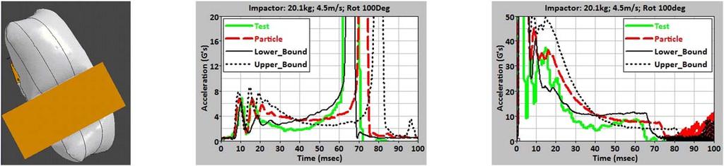
18 Session: Fluid Structure Interaction 13 th International LS-DYNA Users Conference Figure B7. Impactor deceleration pulse and airbag pressure histories of using both particle and uniform pressure methods for 7.1kg impactor with 9.5m/s speed and 100mm distance from the Figure B8. Impactor deceleration pulse and airbag pressure histories of using both particle and uniform pressure methods for 20.1kg impactor with 4.5m/s speed and 100mm distance from the Figure B9. Impactor deceleration pulse and airbag pressure histories of using both particle and uniform pressure methods for 20.1kg impactor with 4.5m/s speed and 100mm distance from the 1-18
Evaluation of LS-DYNA Corpuscular Particle Method Passenger Airbag Applications
 Evaluation of LS-DYNA Corpuscular Particle Method Passenger Airbag Applications Chin-Hsu Lin and Yi-Pen Cheng General Motors Abstract A uniform pressure method, i.e. no pressure variation on bag surface
Investigation of the Early Inflation Characteristics of a Complex Folded Knee Airbag with the New Corpuscular Method in LS-DYNA
 6. LS-DYNA Anwenderforum, Frankenthal 2007 Passive Sicherheit III Investigation of the Early Inflation Characteristics of a Complex Folded Knee Airbag with the New Corpuscular Method in LS-DYNA M. Freisinger
Low Risk Deployment Passenger Airbag CAE Applications & Strategy
 Low Risk Deployment Passenger Airbag CAE Applications & Strategy Bill Feng Jaguar Land Rover Abstract Occupants who were out-of-position (OOP) in the vehicles would increase the risk of airbag induced
Latest FE Model Development of THOR-50M Crash Test Dummy
 Latest FE Model Development of THOR-50M Crash Test Dummy Ismail Maatouki*, Stephen Fu**, Zaifei Zhou**, *Humanetics Europe GmbH, Heidelberg, Germany **Humanetics Innovative Solutions, Inc. Farmington Hills,
PAB Deployment Simulation with Curved Retainer
 7 th International LS-DYNA Users Conference Crash/Safety (3) PAB Deployment Simulation with Curved Retainer Linhuo Shi TG North America Corporation 095 Crooks Road Troy, MI 48084 Tel: (248) 280-7348 Fax:
*MAT GAS MIXTURE, a new gas mixture model for airbag applications
 4 th European LS-DYNA Users Conference Occupant III / Airbag *MAT GAS MIXTURE, a new gas mixture model for airbag applications Author: Lars Olovsson LSTC Correspondence: tel/fax: +46-852 030 881 e-mail:
WorldSID 5% Dummy Model Development in Cooperation with German Automotive Industry
 14 th International LS-DYNA Users Conference Session: Occupant Safety WorldSID 5% Dummy Model Development in Cooperation with German Automotive Industry Sebastian Stahlschmidt, George Dumitru, Yupeng Huang,
EUROPEAN NEW CAR ASSESSMENT PROGRAMME (Euro NCAP) SLED TEST PROCEDURE FOR ASSESSING KNEE IMPACT AREAS
 SLED TEST PROCEDURE FOR ASSESSING KNEE IMPACT AREAS") www.euroncap.com EUROPEAN NEW CAR ASSESSMENT PROGRAMME (Euro NCAP) SLED TEST PROCEDURE FOR ASSESSING KNEE IMPACT AREAS Version 1.0a December 2004 Sled Test Procedure for Assessing Knee Impact Areas (V1.0a)
www.euroncap.com EUROPEAN NEW CAR ASSESSMENT PROGRAMME (Euro NCAP) SLED TEST PROCEDURE FOR ASSESSING KNEE IMPACT AREAS Version 1.0a December 2004 Sled Test Procedure for Assessing Knee Impact Areas (V1.0a)
Example 4 - Airbag. Summary
 Example 4 - Airbag Summary This example deals with the deployment of a chambered airbag modeled by monitored volumes using communications. The airbag is initially folded along four fold lines. The fabric
Developing FE-Tire Model Library for Durability and Crash Simulations
 7 th International LS-DYNA Users Conference Simulation Technology (3) Developing FE-Tire Model Library for Durability and Crash Simulations Masaki Shiraishi*, Naoaki Iwasaki* Tomoharu Saruwatari +, Kimihiro
Application Note AN-107
 SPEC Sensor TM Characterization & Calibration Considerations Scope This document is provided to describe the considerations needed to characterize, calibrate, verify and validate the measurement performance
MADYMO human models for Euro NCAP pedestrian safety assessment
 MADYMO human models for Euro NCAP pedestrian safety assessment Contents Introduction MADYMO Human Models Virtual testing in Euro NCAP Active bonnet safety performance Application of human body models MADYMO
Head Impact Analysis Validation for Aluminium Bonnet
 Head Impact Analysis Validation for Aluminium Bonnet Arda Yüksel 1, Fırat Aras 1, Osman Çolpan 1 1 TOFAS, Bursa TR Abstract In recent years, vehicle manufacturers are making improvements to find more reliable
Injector Dynamics Assumptions and their Impact on Predicting Cavitation and Performance
 Injector Dynamics Assumptions and their Impact on Predicting Cavitation and Performance Frank Husmeier, Cummins Fuel Systems Presented by Laz Foley, ANSYS Outline Overview Computational Domain and Boundary
Paper 2.2. Operation of Ultrasonic Flow Meters at Conditions Different Than Their Calibration
 Paper 2.2 Operation of Ultrasonic Flow Meters at Conditions Different Than Their Calibration Mr William Freund, Daniel Measurement and Control Mr Klaus Zanker, Daniel Measurement and Control Mr Dale Goodson,
ZIN Technologies PHi Engineering Support. PHi-RPT CFD Analysis of Large Bubble Mixing. June 26, 2006
 ZIN Technologies PHi Engineering Support PHi-RPT-0002 CFD Analysis of Large Bubble Mixing Proprietary ZIN Technologies, Inc. For nearly five decades, ZIN Technologies has provided integrated products and
Kyoung-Su Im, Z.-C Zhang, and Grant Cook, Jr. LSTC, Livermore, CA USA. 06/14/2016, Dearborn, MI
 Kyoung-Su Im, Z.-C Zhang, and Grant Cook, Jr. LSTC, Livermore, CA 94551 USA 06/14/2016, Dearborn, MI New Inflator Models! Inflator models In LS-DYNA: Pyrotechnic inflator (PI) model. Hybrid cold flow model
CPM Enhancement for Airbag and Extended Features. Outline
 CPM Enhancement for Airbag and Extended Features 7/2015 Jason Wang jason@lstc.com Copyright 2013 by LIVERMORE SOFTWARE TECHNOLOGY CORPORATION DEM H-Bondp. 1 Outline New Features *AIRBAG_PARTICLE_MOLEFRACTION
Measurement and simulation of the flow field around a triangular lattice meteorological mast
 Measurement and simulation of the flow field around a triangular lattice meteorological mast Matthew Stickland 1, Thomas Scanlon 1, Sylvie Fabre 1, Andrew Oldroyd 2 and Detlef Kindler 3 1. Department of
CFD Simulation and Experimental Validation of a Diaphragm Pressure Wave Generator
 CFD Simulation and Experimental Validation of a Diaphragm Pressure Wave Generator T. Huang 1, A. Caughley 2, R. Young 2 and V. Chamritski 1 1 HTS-110 Ltd Lower Hutt, New Zealand 2 Industrial Research Ltd
End of Chapter Exercises
 End of Chapter Exercises Exercises 1 12 are conceptual questions that are designed to see if you have understood the main concepts of the chapter. 1. While on an airplane, you take a drink from your water
OPTIMIZING THE LENGTH OF AIR SUPPLY DUCT IN CROSS CONNECTIONS OF GOTTHARD BASE TUNNEL. Rehan Yousaf 1, Oliver Scherer 1
 OPTIMIZING THE LENGTH OF AIR SUPPLY DUCT IN CROSS CONNECTIONS OF GOTTHARD BASE TUNNEL Rehan Yousaf 1, Oliver Scherer 1 1 Pöyry Infra Ltd, Zürich, Switzerland ABSTRACT Gotthard Base Tunnel with its 57 km
Paper Session II-C - Verification of International Space Station Component Leak Rates by Helium Accumulation Method
 The Space Congress Proceedings 2003 (40th) Linking the Past to the Future - A Celebration of Space May 1st, 1:30 PM - 4:30 PM Paper Session II-C - Verification of International Space Station Component
Development of Technology to Estimate the Flow Field around Ship Hull Considering Wave Making and Propeller Rotating Effects
 Development of Technology to Estimate the Flow Field around Ship Hull Considering Wave Making and Propeller Rotating Effects 53 MAKOTO KAWABUCHI *1 MASAYA KUBOTA *1 SATORU ISHIKAWA *2 As can be seen from
Investigation on Divergent Exit Curvature Effect on Nozzle Pressure Ratio of Supersonic Convergent Divergent Nozzle
 RESEARCH ARTICLE OPEN ACCESS Investigation on Divergent Exit Curvature Effect on Nozzle Pressure Ratio of Supersonic Convergent Divergent Nozzle Shyamshankar.M.B*, Sankar.V** *(Department of Aeronautical
Golf Ball Impact: Material Characterization and Transient Simulation
 12 th International LS-DYNA Users Conference Blast/Impact(1) Golf Ball Impact: Material Characterization and Transient Simulation Xiaohu Liu, David Quinn and Jorgen Bergström Veryst Engineering, LLC 47A
A STUDY OF THE LOSSES AND INTERACTIONS BETWEEN ONE OR MORE BOW THRUSTERS AND A CATAMARAN HULL
 A STUDY OF THE LOSSES AND INTERACTIONS BETWEEN ONE OR MORE BOW THRUSTERS AND A CATAMARAN HULL L Boddy and T Clarke, Austal Ships, Australia SUMMARY CFD analysis has been conducted on a 100m catamaran hull
LOW PRESSURE EFFUSION OF GASES revised by Igor Bolotin 03/05/12
 LOW PRESSURE EFFUSION OF GASES revised by Igor Bolotin 03/05/ This experiment will introduce you to the kinetic properties of low-pressure gases. You will make observations on the rates with which selected
ANALYSIS OF AERODYNAMIC CHARACTERISTICS OF A SUPERCRITICAL AIRFOIL FOR LOW SPEED AIRCRAFT
 ANALYSIS OF AERODYNAMIC CHARACTERISTICS OF A SUPERCRITICAL AIRFOIL FOR LOW SPEED AIRCRAFT P.Sethunathan 1, M.Niventhran 2, V.Siva 2, R.Sadhan Kumar 2 1 Asst.Professor, Department of Aeronautical Engineering,
MODELLING OF FUME EXTRACTORS C. R.
 LD8 19th International Symposium of Ballistics, 7 11 May 21, Interlaken, Switzerland MODELLING OF FUME EXTRACTORS C. R. Woodley WS4 Guns and Warheads Department, Defence Evaluation and Research Agency,
WindProspector TM Lockheed Martin Corporation
 WindProspector TM www.lockheedmartin.com/windprospector 2013 Lockheed Martin Corporation WindProspector Unparalleled Wind Resource Assessment Industry Challenge Wind resource assessment meteorologists
Comparison of Large-Scale Vented Deflagration Tests to CFD Simulations for Partially Congested Enclosures
 Comparison of Large-Scale Vented Deflagration Tests to CFD Simulations for Partially Congested Enclosures Peter A. Diakow, Project II Consultant, Baker Engineering and Risk Consultants, Inc. J. Kelly Thomas,
Micro Channel Recuperator for a Reverse Brayton Cycle Cryocooler
 Micro Channel Recuperator for a Reverse Brayton Cycle Cryocooler C. Becnel, J. Lagrone, and K. Kelly Mezzo Technologies Baton Rouge, LA USA 70806 ABSTRACT The Missile Defense Agency has supported a research
Analysis of Pressure Rise During Internal Arc Faults in Switchgear
 Analysis of Pressure Rise During Internal Arc Faults in Switchgear ASANUMA, Gaku ONCHI, Toshiyuki TOYAMA, Kentaro ABSTRACT Switchgear include devices that play an important role in operations such as electric
Introduction to Roundabout Analysis Using ARCADY
 Introduction to Roundabout Analysis Using ARCADY Toronto SimCap User Group Technical Event and ITE Toronto Section Social Event July 22, 2014 Phil Weber, P.Eng. GHD Inc. (The Home of Ourston Roundabout
Tutorial. BOSfluids. Relief valve
 Tutorial Relief valve The Relief valve tutorial describes the theory and modeling process of a pressure relief valve or safety valve. It covers the algorithm BOSfluids uses to model the valve and a worked
End of Chapter Exercises
 End of Chapter Exercises Exercises 1 12 are conceptual questions that are designed to see if you have understood the main concepts of the chapter. 1. While on an airplane, you take a drink from your water
Examination of Human Body Mass Influence on Pedestrian Pelvis Injury Prediction Using a Human FE Model
 IRC-2 IRCOBI Conference 22 Examination of Human Body Mass Influence on Pedestrian Pelvis Injury Prediction Using a Human FE Model Yasuaki Gunji, Masayoshi Okamoto, Yukou Takahashi Abstract This research
FUNDAMENTALS OF PRESSURE REGULATORS ROBERT BENNETT MANAGER OF TRAINING ELSTER AMERICAN METER
 FUNDAMENTALS OF PRESSURE REGULATORS ROBERT BENNETT MANAGER OF TRAINING ELSTER AMERICAN METER SUPPLY = DEMAND FUNCTION OF A REGULATOR A regulator may be defined as a "mechanism for controlling or governing
Computational analysis of fish survival at the John Day Powerhouse
 Computational analysis of fish survival at the John Day Powerhouse Jim Kiel Laurie Ebner Introduction Design a CFD model that can be used to predict the pressures in the turbine runner environment. What
Entry Descent and Landing Tools
 Entry Descent and Landing Tools Steve Lingard Vorticity Ltd Oxfordshire,UK Content Introduction Entry and Descent Dynamics Tools Airbag Design Environment LS-DYNA Applications Entry system dynamics Inflatable
485 Annubar Primary Flow Element Installation Effects
 ROSEMOUNT 485 ANNUBAR 485 Annubar Primary Flow Element Installation Effects CONTENTS Mounting hole diameter Alignment error Piping Geometry Induced Flow Disturbances Pipe reducers and expansions Control
Huntsman Polyurethanes smart simulation software. Process optimization by simulation
 Huntsman Polyurethanes smart simulation software Process optimization by simulation Understanding material behavior is fundamental to the design of new products. For non-linear materials such as molding
CFD Analysis and Experiment Study of the Rotary Two-Stage Inverter Compressor with Vapor Injection
 Purdue University Purdue e-pubs International Compressor Engineering Conference School of Mechanical Engineering 2016 CFD Analysis and Experiment Study of the Rotary Two-Stage Inverter Compressor with
Finite Element Analysis of an Aluminium Bike Frame
 Finite Element Analysis of an Aluminium Bike Frame Word Count: 1484 1 1. Introduction Each new bike model must pass a series of structural tests before being released for public retail. The purpose of
MODELING&SIMULATION EXTRAPOLATED INTERNAL ARC TEST RESULTS: A COUPLED FLUID-STRUCTURAL TRANSIENT METHODOLOGY
 MODELING&SIMULATION EXTRAPOLATED INTERNAL ARC TEST RESULTS: A COUPLED FLUID-STRUCTURAL TRANSIENT METHODOLOGY Jérôme DOUCHIN Schneider Electric France Jerome.douchin@schneider-electric.com Ezequiel Salas
Vibration-Free Joule-Thomson Cryocoolers for Distributed Microcooling
 Vibration-Free Joule-Thomson Cryocoolers for Distributed Microcooling W. Chen, M. Zagarola Creare Inc. Hanover, NH, USA ABSTRACT This paper reports on an innovative concept for a space-borne Joule-Thomson
AC : A LABORATORY EXERCISE TO DEMONSTRATE HOW TO EXPERIMENTALLY DETERMINE THE OPERATING POINT FOR A FAN
 AC 2007-206: A LABORATORY EXERCISE TO DEMONSTRATE HOW TO EXPERIMENTALLY DETERMINE THE OPERATING POINT FOR A FAN Robert Edwards, Pennsylvania State University-Erie Robert Edwards is currently a Lecturer
Agilent Dimension Software for ELSD User Manual
 Agilent Dimension Software for ELSD User Manual Agilent Dimension Software for ELSD User Manual Agilent Technologies Notices Agilent Technologies, Inc. 2011 No part of this manual may be reproduced in
Process Simulator Evaluates Blower and Valve Control Strategies for WWTP Aeration
 Process Simulator Evaluates Blower and Valve Control Strategies for WWTP Aeration inshare By Steve Kestel and Tilo Stahl (BioChem Technology) and Matthew Gray (Keystone Engineering Group) Introduction
CFD and Physical Modeling of DSI/ACI Distribution
 CFD and Physical Modeling of DSI/ACI Distribution APC Round Table & Exposition July 09, 2013 Matt Gentry mgentry@airflowsciences.com 734-525-0300 1 Outline Introduction Flow Analysis Techniques Application
HYDROGEN FAST FILLING TO A TYPE IV TANK DEVELOPED FOR MOTORCYCLES
 HYDROGEN FAST FILLING TO A TYPE IV TANK DEVELOPED FOR MOTORCYCLES Yamada, E. 1, Hiraki, W. 2, and Muramatsu, H. 3 1 FC-EV Research Division, Japan Automobile Research Institute, 1328-23 Takaheta, Osaka,
Sensitivity Analysis for Pedestrian Lower Leg Impact
 Proceedings of the 7th GACM Colloquium on Computational Mechanics for Young Scientists from Academia and Industry October 11-13, 2017 in Stuttgart, Germany Sensitivity Analysis for Pedestrian Lower Leg
POWER Quantifying Correction Curve Uncertainty Through Empirical Methods
 Proceedings of the ASME 2014 Power Conference POWER2014 July 28-31, 2014, Baltimore, Maryland, USA POWER2014-32187 Quantifying Correction Curve Uncertainty Through Empirical Methods ABSTRACT Christopher
Aalborg Universitet. Published in: Proceedings of Offshore Wind 2007 Conference & Exhibition. Publication date: 2007
 Aalborg Universitet Design Loads on Platforms on Offshore wind Turbine Foundations with Respect to Vertical Wave Run-up Damsgaard, Mathilde L.; Gravesen, Helge; Andersen, Thomas Lykke Published in: Proceedings
Qian Wang, Tanya Kapoor, William Altenhof University of Windsor Department of Mechanical Automotive and Materials Engineering
 9 th International LS-DYNA Users Conference Crash/Safety (2) A Numerical Investigation into the Injury Potential of Three-year-old Children Seated in Forward Facing Child Safety Seats During Side Impact
EUROPEAN NEW CAR ASSESSMENT PROGRAMME (Euro NCAP) SLED TEST PROCEDURE FOR ASSESSING KNEE IMPACT AREAS. For 2020 implementation
 SLED TEST PROCEDURE FOR ASSESSING KNEE IMPACT AREAS. For 2020 implementation") EUROPEAN NEW CAR ASSESSMENT PROGRAMME (Euro NCAP) SLED TEST PROCEDURE FOR ASSESSING KNEE IMPACT AREAS For 2020 implementation Copyright Euro NCAP 2018 - This work is the intellectual property of Euro NCAP.
EUROPEAN NEW CAR ASSESSMENT PROGRAMME (Euro NCAP) SLED TEST PROCEDURE FOR ASSESSING KNEE IMPACT AREAS For 2020 implementation Copyright Euro NCAP 2018 - This work is the intellectual property of Euro NCAP.
Surrounding buildings and wind pressure distribution on a high rise building
 Surrounding buildings and wind pressure distribution on a high rise building Conference or Workshop Item Accepted Version Luo, Z. (2008) Surrounding buildings and wind pressure distribution on a high rise
Special edition paper
 Development of Train Nose Shape for Reducing Micro-pressure Waves Takeshi Kurita*, Yoichi Okumura* and Tsuyoshi Ichigi** To ensure that the micro-pressure waves generated during high speed running are
EFFECTIVE DESIGN OF CONVERTER HOODS. 111 Ferguson Ct. Suite 103 Irving, Texas U.S.A. 400 Carlingview Dr. Toronto, ON M9W 5X9 Canada.
 EFFECTIVE DESIGN OF CONVERTER HOODS Paykan Safe 1, Sam Matson 1, and John Deakin 2 1 Gas Cleaning Technologies 111 Ferguson Ct. Suite 103 Irving, Texas 75062 U.S.A. 2 H.G. Engineering, Ltd. 400 Carlingview
Acoustical Modeling of Reciprocating Compressors With Stepless Valve Unloaders
 Acoustical Modeling of Reciprocating Compressors With Stepless Valve Unloaders Kelly Eberle, P.Eng. Principal Engineer keberle@betamachinery.com Brian C. Howes, M.Sc., P.Eng. Chief Engineer bhowes@betamachinery.com
Traffic Parameter Methods for Surrogate Safety Comparative Study of Three Non-Intrusive Sensor Technologies
 Traffic Parameter Methods for Surrogate Safety Comparative Study of Three Non-Intrusive Sensor Technologies CARSP 2015 Collision Prediction and Prevention Approaches Joshua Stipancic 2/32 Acknowledgements
STATIC AND DYNAMIC EVALUATION OF THE DRIVER SPEED PERCEPTION AND SELECTION PROCESS
 STATIC AND DYNAMIC EVALUATION OF THE DRIVER SPEED PERCEPTION AND SELECTION PROCESS David S. Hurwitz, Michael A. Knodler, Jr. University of Massachusetts Amherst Department of Civil & Environmental Engineering
Ignition modelling Are our approaches aligned?
 Ignition modelling Are our approaches aligned? Lars Rogstadkjernet Gexcon Outline Experience from 3 rd party reviews Areas of diverging approach Dispersion and ignition modelling 3 rd party reviews 3 rd
LOW PRESSURE EFFUSION OF GASES adapted by Luke Hanley and Mike Trenary
 ADH 1/7/014 LOW PRESSURE EFFUSION OF GASES adapted by Luke Hanley and Mike Trenary This experiment will introduce you to the kinetic properties of low-pressure gases. You will make observations on the
Application of Simulation Technology to Mitsubishi Air Lubrication System
 50 Application of Simulation Technology to Mitsubishi Air Lubrication System CHIHARU KAWAKITA *1 SHINSUKE SATO *2 TAKAHIRO OKIMOTO *2 For the development and design of the Mitsubishi Air Lubrication System
WorldSID 50th vs. ES-2. A Comparison Based on Simulations.
 9. LS-DYNA Forum, Bamberg 2010 Passive Sicherheit I - Dummymodelle WorldSID 50th vs. ES-2. A Comparison Based on Simulations. Sebastian Stahlschmidt, Alexander Gromer DYNAmore GmbH, Stuttgart, Germany
Tightening Evaluation of New 400A Size Metal Gasket
 Proceedings of the 8th International Conference on Innovation & Management 307 Tightening Evaluation of New 400A Size Metal Gasket Moch. Agus Choiron 1, Shigeyuki Haruyama 2, Ken Kaminishi 3 1 Doctoral
Development of TEU Type Mega Container Carrier
 Development of 8 700 TEU Type Mega Container Carrier SAKAGUCHI Katsunori : P. E. Jp, Manager, Ship & Offshore Basic Design Department, IHI Marine United Inc. TOYODA Masanobu : P. E, Jp, Ship & Offshore
Evaluation of Work Zone Strategies at Signalized Intersections
 Evaluation of Work Zone Strategies at Signalized Intersections Khaled Shaaban Qatar University/Department of Civil and Architectural Engineering, Doha, Qatar Email: kshaaban@qu.edu.qa Dina Elnashar Qatar
Time Pressure Dispensing
 Time Pressure Dispensing by Doug Dixon, GDM Product Manager What is time pressure dispensing? Time pressure is a method of dispensing liquid materials (surface mount adhesives and gasketing materials)
Autodesk Moldflow Communicator Process settings
 Autodesk Moldflow Communicator 212 Process settings Revision 1, 3 March 211. Contents Chapter 1 Process settings....................................... 1 Profiles.................................................
A Study on Roll Damping of Bilge Keels for New Non-Ballast Ship with Rounder Cross Section
 International Ship Stability Workshop 2013 1 A Study on Roll Damping of Bilge Keels for New Non-Ballast Ship with Rounder Cross Section Tatsuya Miyake and Yoshiho Ikeda Department of Marine System Engineering,
CONTENTS 1. INTRODUCTION DESCRIPTION OF TEST SAMPLE TEST RIG GENERAL ARRANGEMENT TEST SEQUENCE...7
 Page 2 of 22 CONTENTS 1. INTRODUCTION...3 2. DESCRIPTION OF TEST SAMPLE...4 3. TEST RIG GENERAL ARRANGEMENT...6 4. TEST SEQUENCE...7 5. SUMMARY AND CLASSIFICATION OF TEST RESULTS...8 6. WATERTIGHTNESS
Hydronic Systems Balance
 Hydronic Systems Balance Balancing Is Misunderstood Balancing is application of fundamental hydronic system math Balance Adjustment of friction loss location Adjustment of pump to requirements By definition:
Numerical and Experimental Investigation of the Possibility of Forming the Wake Flow of Large Ships by Using the Vortex Generators
 Second International Symposium on Marine Propulsors smp 11, Hamburg, Germany, June 2011 Numerical and Experimental Investigation of the Possibility of Forming the Wake Flow of Large Ships by Using the
Incorporating 3D Suction or Discharge Plenum Geometry into a 1D Compressor Simulation Program to Calculate Compressor Pulsations
 Purdue University Purdue e-pubs International Compressor Engineering Conference School of Mechanical Engineering 2012 Incorporating 3D Suction or Discharge Plenum Geometry into a 1D Compressor Simulation
Impulsive Pressurization of Neuronal Cells. M. Nienaber, J.S. Lee, R. Feng and J.Y. Lim
 Impulsive Pressurization of Neuronal Cells M. Nienaber, J.S. Lee, R. Feng and J.Y. Lim Department of Engineering Mechanics University Nebraska-Lincoln Lincoln, NE 68588-0526 Work Supported by ARO 47th
REAL. Simple, Intuitive, Powerful Real.
 REAL Simple, Intuitive, Powerful Real. When we set out to define the bikefitting.com toolset engineered by Shimano Dynamics Lab, these were a few of the stand out priorities we wanted to achieve. We delivered.
Copyright by Turbomachinery Laboratory, Texas A&M University
 Proceedings of the 2 nd Middle East Turbomachinery Symposium 17 20 March, 2013, Doha, Qatar Effectiveness of Windage Features on High Speed Couplings Steven Pennington Global Engineering Manager John Crane
EFFECTS OF SIDEWALL OPENINGS ON THE WIND LOADS ON PIPE-FRAMED GREENHOUSES
 The Seventh Asia-Pacific Conference on Wind Engineering, November 8-12, 29, Taipei, Taiwan EFFECTS OF SIDEWALL OPENINGS ON THE WIND LOADS ON PIPE-FRAMED GREENHOUSES Yasushi Uematsu 1, Koichi Nakahara 2,
Available online at ScienceDirect. Procedia Engineering 112 (2015 )
") Available online at www.sciencedirect.com ScienceDirect Procedia Engineering 112 (2015 ) 540 545 7th Asia-Pacific Congress on Sports Technology, APCST 2015 Movement variability of professional pool billiards
Available online at www.sciencedirect.com ScienceDirect Procedia Engineering 112 (2015 ) 540 545 7th Asia-Pacific Congress on Sports Technology, APCST 2015 Movement variability of professional pool billiards
CORRELATION EFFECTS IN THE FIELD CLASSIFICATION OF GROUND BASED REMOTE WIND SENSORS
 CORRELATION EFFECTS IN THE FIELD CLASSIFICATION OF GROUND BASED REMOTE WIND SENSORS Will Barker (1), Julia Gottschall (2), Michael Harris (3), John Medley (4), Edward Burin des Roziers (5), Chris Slinger
Characteristics of Decompression Tank Internally Pressurized With Water Using OpenFOAM Syamsuri 1, a
 Applied Mechanics and Materials Submitted: 2015-11-26 ISSN: 1662-7482, Vol. 836, pp 3-8 Accepted: 2016-01-27 doi:10.4028/www.scientific.net/amm.836.3 Online: 2016-06-01 2016 Trans Tech Publications, Switzerland
Lab # 03: Visualization of Shock Waves by using Schlieren Technique
 AerE545 Lab # 03: Visualization of Shock Waves by using Schlieren Technique Objectives: 1. To get hands-on experiences about Schlieren technique for flow visualization. 2. To learn how to do the optics
AC : MEASUREMENT OF HYDROGEN IN HELIUM FLOW
 AC 2010-2145: MEASUREMENT OF HYDROGEN IN HELIUM FLOW Randy Buchanan, University of Southern Mississippi Christopher Winstead, University of Southern Mississippi Anton Netchaev, University of Southern Mississippi
CALIBRATION AND VERIFICATION OF DETAILED HYBRID III 50 TH PERCENTILE MALE ANTHROPOMORPHIC TEST DEVICE (ATD) BASED ON EXTENSIVE MINE BLAST TESTS
 BASED ON EXTENSIVE MINE BLAST TESTS") 2017 NDIA GROUND VEHICLE SYSTEMS ENGINEERING AND TECHNOLOGY SYMPOSIUM MODELING & SIMULATION, TESTING AND VALIDATION (MSTV) TECHNICAL SESSION AUGUST 8-10, 2017 - NOVI, MICHIGAN CALIBRATION AND VERIFICATION
2017 NDIA GROUND VEHICLE SYSTEMS ENGINEERING AND TECHNOLOGY SYMPOSIUM MODELING & SIMULATION, TESTING AND VALIDATION (MSTV) TECHNICAL SESSION AUGUST 8-10, 2017 - NOVI, MICHIGAN CALIBRATION AND VERIFICATION
ENHANCED PARKWAY STUDY: PHASE 2 CONTINUOUS FLOW INTERSECTIONS. Final Report
 Preparedby: ENHANCED PARKWAY STUDY: PHASE 2 CONTINUOUS FLOW INTERSECTIONS Final Report Prepared for Maricopa County Department of Transportation Prepared by TABLE OF CONTENTS Page EXECUTIVE SUMMARY ES-1
Lane changing and merging under congested conditions in traffic simulation models
 Urban Transport 779 Lane changing and merging under congested conditions in traffic simulation models P. Hidas School of Civil and Environmental Engineering, University of New South Wales, Australia Abstract
The reduction of peak overpressure using concrete blast barriers
 Structures Under Shock and Impact XIII 265 The reduction of peak overpressure using concrete blast barriers R. Hájek & M. Foglar Department of Concrete and Masonry Structures, Faculty of Civil Engineering,
AIRMOUNT VIBRATION ISOLATION
 MOUNT VIBRATION ISOLATION SELECTION AND ISOLATION FORMULA Refer to the selection guide on page 33 for Airmount load and isolation capabilities. Follow this procedure: 1. LOAD CAPACITY Select one or two
Computer Simulation Helps Improve Vertical Column Induced Gas Flotation (IGF) System
 System") JOURNAL ARTICLES BY FLUENT SOFTWARE USERS JA187 Computer Simulation Helps Improve Vertical Column Induced Gas Flotation (IGF) System Computer simulation has helped NATCO engineers make dramatic improvements
JOURNAL ARTICLES BY FLUENT SOFTWARE USERS JA187 Computer Simulation Helps Improve Vertical Column Induced Gas Flotation (IGF) System Computer simulation has helped NATCO engineers make dramatic improvements
Best Practice RBI Technology Process by SVT-PP SIMTECH
 Best Practice RBI Technology Process by SVT-PP SIMTECH We define the best practice in RBI as a proactive technology process which is used to formally and reliably optimise the inspection efforts for each
FIRE PROTECTION. In fact, hydraulic modeling allows for infinite what if scenarios including:
 By Phil Smith, Project Manager and Chen-Hsiang Su, PE, Senior Consultant, Lincolnshire, IL, JENSEN HUGHES A hydraulic model is a computer program configured to simulate flows for a hydraulic system. The
OPTIMIZATION OF SINGLE STAGE AXIAL FLOW COMPRESSOR FOR DIFFERENT ROTATIONAL SPEED USING CFD
 http:// OPTIMIZATION OF SINGLE STAGE AXIAL FLOW COMPRESSOR FOR DIFFERENT ROTATIONAL SPEED USING CFD Anand Kumar S malipatil 1, Anantharaja M.H 2 1,2 Department of Thermal Power Engineering, VTU-RO Gulbarga,
International Journal of Technical Research and Applications e-issn: , Volume 4, Issue 3 (May-June, 2016), PP.
, PP.") DESIGN AND ANALYSIS OF FEED CHECK VALVE AS CONTROL VALVE USING CFD SOFTWARE R.Nikhil M.Tech Student Industrial & Production Engineering National Institute of Engineering Mysuru, Karnataka, India -570008
DESIGN AND ANALYSIS OF FEED CHECK VALVE AS CONTROL VALVE USING CFD SOFTWARE R.Nikhil M.Tech Student Industrial & Production Engineering National Institute of Engineering Mysuru, Karnataka, India -570008
IAC-06-D4.1.2 CORRELATIONS BETWEEN CEV AND PLANETARY SURFACE SYSTEMS ARCHITECTURE PLANNING Larry Bell
 IAC-06-D4.1.2 CORRELATIONS BETWEEN CEV AND PLANETARY SURFACE SYSTEMS ARCHITECTURE PLANNING Larry Bell Sasakawa International Center for Space Architecture (SICSA), University of Houston, USA e-mail: lbell@uh.edu
Introductory Lab: Vacuum Methods
 Introductory Lab: Vacuum Methods Experiments in Modern Physics (P451) In this lab you will become familiar with the various components of the lab vacuum system. There are many books on this topic one of
Wind Flow Validation Summary
 IBHS Research Center Validation of Wind Capabilities The Insurance Institute for Business & Home Safety (IBHS) Research Center full-scale test facility provides opportunities to simulate natural wind conditions
AIRFLOW GENERATION IN A TUNNEL USING A SACCARDO VENTILATION SYSTEM AGAINST THE BUOYANCY EFFECT PRODUCED BY A FIRE
 - 247 - AIRFLOW GENERATION IN A TUNNEL USING A SACCARDO VENTILATION SYSTEM AGAINST THE BUOYANCY EFFECT PRODUCED BY A FIRE J D Castro a, C W Pope a and R D Matthews b a Mott MacDonald Ltd, St Anne House,