Operation Manual. Carbon Filtration Industrial Drive, Orlinda, TN fax
|
|
|
- Donald Lane
- 5 years ago
- Views:
Transcription


1 Operation Manual Carbon Filtration fax


2 TABLE OF CONTENTS Section 1 GENERAL 1.1 Warnings and Cautions Theory of Operation System Illustration... 3 Section 2 SPECIFICATIONS 2.1 Water & Electrical Requirements Specifications... 4 Section 3 INSTALLATION 3.1 Installation... 5 Section 4 OPERATION 4.1 Operation... 6 Section 5 ROUTINE MAINTENANCE 5.1 Troubleshooting Routine Maintenance sales@specialtyh2o.com fax
3 Section 1.1 WARNINGS AND CAUTIONS WARNINGS Read this manual in its entirety before operating the Carbon Filtration System. Misuse, improper operation, and/or improper monitoring of this equipment could result in serious injury, death, or other serious reactions to the end users of the equipment. CAUTIONS When used as a medical device, Federal law restricts this device to sale by or on the authority of a physician. Per CFR (b)(1). It is the responsibility of the governing body of the facility to ensure that all applicable regulations regarding the installation and operation of this system are observed. Only authorized personnel can install, perform service, or perform maintenance to the Carbon Filtration System. To be used only for pre-treatment of water prior to reverse osmosis (RO) sales@specialtyh2o.com fax 1
4 Section 1.2 THEORY OF OPERATION Carbon filtration is based upon a naturally occurring phenomenon called adsorption, in which molecules of a liquid or gas are trapped by either the external or internal surface of a solid. Activated carbon has a very high internal surface area and thus is an ideal material for adsorption. Raw water quality can be improved with the removal of trace components. Carbon filters are backwashed periodically (every other day) to expose new adsorption sites in the media. After backwash, a down-flow rinse prepares the media for service. Carbon filtration consist of at least 2 properly sized pressure vessels (tanks) which are filled with predetermined volumes of carbon. In most systems, two properly sized, backwashable carbon filters are connected in series with tank #1 adsorbing the entire load (worker) and tank #2 performing a polishing task (polisher) while providing a back-up capability. Each carbon filter in the system has a 7 day calendar time clock to control backwashing. The controller can be set to backwash at pre-set times on specific days, giving the user maximum flexibility. The controller has an interlock feature to prevent the RO from running during the backwash cycle. When backwashing a red light is illuminated as an indicator of this cycle and the RO will not run due to the interlock. The carbon selected is of the highest quality available and meets our demanding specifications for chlorine/chloramine removal. The carbon is granular activated, acid washed, and designed for the purification of aqueous liquids which may be sensitive to acid soluble constituents such as iron sales@specialtyh2o.com fax 2

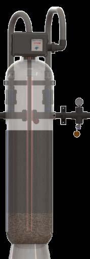
5 Section 1.3 SYSTEM ILLUSTRATION Fleck Control Head Fleck Digital Timer Strainer (Under Gravel) fax 3
6 Section 2.1 SPECIFICATIONS ELECTRICAL AND WATER REQUIREMENTS: Water Requirements: Electrical Requirements: Drain Requirements: Tempered water. 120 VAC from uninterruptable, ground fault protected. Must facilitate up to 65 gpm. SPECIFICATIONS: **Each Model Series Consists of W (Worker) and P (Polisher) 2 Tank Set MODEL 4E F G G H H K Tank Size 16x65 18x65 21x62 21x62 24x72 24x72 30x72 Media Cu. Ft Service 10 ECBT 6 gpm 7.5 gpm 9 gpm 10.5 gpm 12 gpm 15 gpm 18 gpm Drain Flow 12 gpm 15 gpm 20 gpm 20 gpm 25 gpm 25 gpm 45 gpm Pressure Drop (Δ) < 6 psi < 6 psi < 6 psi < 9 psi < 9 psi < 9 psi < 9 psi Control Head Fleck 2750 Fleck 2850 Fleck 2850-S Control Timer Fleck SXT Digital Port Inlet 1 1 ½ Port Outlet 1 1 ½ Drain 1 1 ¼ Carbon Acid Washed, Minimum Iodine # of 900 Carbon (12x40) 4 cu/ft 5 cu/ft 6 cu/ft 7 cu/ft 8 cu/ft 10 cu/ft 12 cu/ft Gravel (1/4 ) 50 lbs 75 lbs 100 lbs 100 lbs 150 lbs 150 lbs 200 lbs sales@specialtyh2o.com fax 4
7 Section 2.1 SPECIFICATIONS SPECIFICATIONS: (continued) **Each Model Series Consists of W (Worker) and P (Polisher) 2 Tank Set MODEL 4K K M M M M M Tank Size 30x72 30x72 36x72 36x72 36x72 36x72 36x72 Media Cu. Ft Service 10 ECBT 21 gpm 22.5 gpm 24 gpm 25.5 gpm 27 gpm 30 gpm 31.5 gpm Drain Flow 45 gpm 45 gpm 65 gpm 65 gpm 65 gpm 65 gpm 65 gpm Pressure Drop (Δ) < 9 psi < 9 psi < 12 psi < 12 psi < 12 psi < 12 psi < 12 psi Control Head Fleck 2850-S Control Timer Fleck SXT Digital Port Inlet 1 ½ Port Outlet 1 ½ Drain 1 ¼ Carbon Acid Washed, Minimum Iodine # of 900 Carbon (12x40) 14 cu/ft 15 cu/ft 16 cu/ft 17 cu/ft 18 cu/ft 20 cu/ft 21 cu/ft Gravel (1/4 ) 200 lbs 200 lbs 300 lbs 300 lbs 300 lbs 300 lbs 300 lbs * Other sized tanks are available as well as custom tanks and applications sales@specialtyh2o.com fax 5
8 Section 3.1 INSTALLATION 1. The carbon filter must be placed before the softener (unless an organic scavenger is installed in which the carbon filter will go after the softener). Identify the location where the unit will be placed and verify that it is in a welllit, with level, smooth floor, easy access location with access to a 120 VAC electrical outlet. 2. The unit will be connected by 1 ½ (or 2 ) PVC hose into the pretreatment water supply manifold. It needs to have a bypass valve and inlet and outlet valve ready to connect to the multi-media filter. 3. You will need a drain for the backwashing cycles. If possible, the drain should be no farther than 20 feet from the filter. You will need to purchase this flexible 1, 1 ¼ or 2 diameter plastic tubing from SWT. The tubing can be vinyl, polyethylene, polybutylene, etc. The drain line will be under pressure when the backwash cycle is working, therefore make sure the drain line is secured. The drain line will need to dump into a drain that is a diameter of 1 ½" to 2 and ideally be below the top of the head of your filter. All local building codes should be adhered to. Never connect the drain line directly into a drain. Allow an air gap between the drain tubing and waste line to prevent the possibility of reverse siphoning. A (DAG) Drain Air Gap Assembly can be used. 4. Put the distributor tube (riser) into the media tank, the screen intake/strainer will be at the bottom and the open end of the tube will be at the top. The screen/strainer should be resting on the bottom and centered. 5. Use masking tape or scotch tape to tape over the open end of the riser tube. This is to keep any media from falling into the tube while pouring the media into the tank. 6. Place a funnel into the tank and pour the entire contents of each box or bag in the following order to fill the tank from bottom to top: a. Gravel b. Carbon 7. While filling the bottom of the tank with gravel be careful to keep the distributor/riser centered as best you can. Once the filling of the tank is completed, remove the tape from the distributor/riser. Do NOT pull upwards on the tube! sales@specialtyh2o.com fax 6
9 Section 3.1 INSTALLATION 8. The control valve (head) must be screwed in to the top of the tank. As you start to screw the control valve into the tank make sure the hole in the center of the control valve fits over the distributor/riser tube. NO pipe dope should be used on the threads. The control valve should be hand tightened, snugly, clockwise. Try not to over tighten the control valve, over tighteneing can make future removal difficult. The control valve contrains an O-ring in a grooved slot, and serves as the primary tank-to-valve seal. After the control valve is threaded into the tank, rotate the tank to align the control head facing forward. 9. Located between the inlet and outlet water connection on the by-pass valve, you will find a male 1, 1 ¼ or 2 inch threaded (NPT) nipple. This is the connection for your drain line. Be sure it is connected as per the instructions in step 3 (above). You can connect flexible tubing to a 90 hose barb fitting. If you decide to use this connection method, wrap the threaded nipple with Teflon tape prior to connecting the 90 fitting. It s advisable to use a metal hose clamp to secure the tubing onto the barb fitting. 10. Make sure the main water supply is off. Depress the Red Pointer Knob and turn the knob counter- clockwise into the backwash position. With the water supply off, place the bypass valve into the service position. (For digital fleck heads please refer to the manual that is supplied) Open the water supply valve very slowly to approximately the 1/4 open position. In this position, you should hear air escaping slowly from the drain line. CAUTION: If opened too rapidly or too far, some filter media may be lost and plugging of the valve is possible. 11. Check for leaks and re-tape or re-tighten any loose or leaking fittings. 12. When water begins to flow steadily from the drain, signifying the air has been purged from the tank, open the main water supply valve all the way. You will notice that the water running in the drain line is slightly cloudy or discolored. This is normal, and you are now backwashing a small amount of fine material contained in the filter media from the bed. After the water in the drain line is running clear to the drain (this can sometimes take up to 1 hour), initiate a manual backwash by turning the red pointer knob to the indicated position or per the instruction for a digital head, and allow the unit to run through a complete cycle sales@specialtyh2o.com fax 7
10 Section 3.1 INSTALLATION 13. Now refer to the manual that was supplied with you specific model and set the time and backwash cycle frequency as directed. We recommend that you set the filter to backwash three to four times each week. It is good practice to be present at your first full cycle of back wash to make any adjustments needed to assure a complete back wash of the whole filtering system. 14. If a water softener or reverse osmosis system is to be installed downstream of a backwashing filter, make sure that the by-pass valve on the water softener is in by-pass during filter installation. This will guarantee that this equipment is not contaminated with an excessive amount of filter media. You can take the equipment out of by-pass when water from filter is running clear. 15. Conduct a chlorine/chlorimine test to ensure there is no faulty connections with the riser tube or strainer. If the total chlorine level is >0.1ppm then the filter needs to be taken offline and rechecked/repaired until a good reading is obtained sales@specialtyh2o.com fax 8
11 Section 4.1 OPERATION 1. The operations of the carbon filter system is completely automatic. Once the system has been setup, little operator action is necessary. Setting Timer See Control Head Manual for details. Control Head See Control Head Manual for details fax 9
12 Section 5.1 ROUTINE MAINTENANCE TROUBLESHOOTING GUIDE Problem Possible Causes Possible Solutions The filter backwashes at unscheduled times. Filter has a pressure drop greater than 15 psi. Chlorine break-through has occurred. Problem with automatic control valve or time clock Pretreatment component needs to be backwashed or regenerated more often Media exhausted Carbon media failure Possible problem with organic scavenger or sediment filters. Check the time of day on the controller and adjust if necessary. Using the manufacturer s instructions set the controller to backwash more often. If this fails to correct the problem, the tank must be emptied, cleaned, and rebedded. NOTE: When re-bedding, always install a new distributor. Facility staff should be made aware of the situation immediately. If the level of Total Chlorine exiting the first tank exceeds 0.1 mg/l, a sample should immediately be drawn from the water exiting the second tank. If that water meets the AAMI standard, dialysis can proceed; however, arrangements should be made to replace the first tank. If the chloramine level in the effluent of the second tank also exceeds 0.1 mg/l, that water must not be used for dialysis. The tank must be removed from service and re-bedded. Ensure the manufacturer s instructions are followed and only specified carbon and gravel are used sales@specialtyh2o.com fax 10
13 Section 5.1 ROUTINE MAINTENANCE 1. Daily monitoring checking the pressures along with the Delta Pressure (pressure drop) across the filter while the RO is running. 2. Daily monitoring should be done to ensure that chlorine/chloramine free water is available prior to each hemodialysis treatment shift. This requires testing for chlorine/chloramine before the first treatment of the day and prior to each treatment shift throughout the day. 3. The media in the tank should be changed (re-bedded) when the pressure drop across the filter is greater than 15 psi when the RO is running and is consistent even after a backwash cycle. 4. The media in the tank should be changed (re-bedded) if the chlorine/ chloramines breakthrough is greater than 0.1 ppm after two verified backwashing cycles sales@specialtyh2o.com fax 11
14 Carbon Filter Operation Manual Rev. 8_2015 Manual P/N: OM-CARBON-FILTER fax
1020 Industrial Drive, Orlinda, TN fax
 Operation Manual Ultrafiltration for High Purity Distribution K-A-HPTUF Series 615-654-4441 sales@specialtyh2o.com 615-654-4449 fax TABLE OF CONTENTS Section 1 GENERAL 1.1 Warnings and Cautions... 1 1.2
Softeners Clack Model V125DTH Medical / Industrial Series Operation and Service Manual
 Softeners Clack Model V125DTH Medical / Industrial Series Operation and Service Manual www.ameriwater.com 800-535-5585 AmeriWater LLC 3345 Stop 8 Rd. Dayton, OH 45414 Clack Softener Manual, 98-0180 Rev.
Easy Nest Kits. Installation Suggestions
 Easy Nest Kits Installation Suggestions 2 General Recommendations Hydraulics Vacuum breakers should be installed to prevent siphoning. Flexible connectors should follow FRP tank manufacturers recommendations.
INSTALLATION & START-UP INSTRUCTIONS. Clack WS1 & WS1.25 METER WATER SOFTENER SYSTEMS
 INSTALLATION & START-UP INSTRUCTIONS Clack WS1 & WS1.25 METER WATER SOFTENER SYSTEMS 1999-2009 QualityWaterForLess.com - 1 - info@qualitywaterforless.com Preface: Thank you for your purchase of a new Water
INSTALLATION & START-UP INSTRUCTIONS FLECK 9100SXT METER TWIN ALTERNATING WATER SOFTENER SYSTEMS
 INSTALLATION & START-UP INSTRUCTIONS FLECK 9100SXT METER TWIN ALTERNATING WATER SOFTENER SYSTEMS 1999-2007 QualityWaterForLess.com - 1 - info@qualitywaterforless.com Preface: Thank you for your purchase
Owners Manual Models: 075-AQF-CX. Aquatrol Backwashing Catalytic Carbon Filter. Visit us online at.
 Visit us online at www.uswatersystems.com Aquatrol Backwashing Catalytic Carbon Filter Owners Manual Models: 075-AQF-CX REVISION # 1.0 REVISION DATE October 11, 2017 US Water Systems, Inc. 1209 Country
O&M Receiving and Inspection. Storage of Water Treatment Media
 O&M 105.1 Receiving and Inspection 1. Equipment should be checked against the Bill of Lading to verify that the number of pieces received matches those shipped. 2. Equipment should be carefully inspected
1020 Industrial Drive, Orlinda, TN fax
 Operation Manual Tank Distribution System A-UPT Series 615-654-4441 sales@specialtyh2o.com 615-654-4449 fax TABLE OF CONTENTS Section 1 GENERAL 1.2 Warnings and Cautions... 1 1.2 Theory of Operation...
Softener / Filter Fleck Model 2850 SXT Medical / Industrial Series Operation and Service Manual
 Softener / Filter Fleck Model 2850 SXT Medical / Industrial Series Operation and Service Manual www.ameriwater.com 800-535-5585 AmeriWater 3345 Stop 8 Rd. Dayton, OH 45414 98-0107 Rev. I 2018-02-09 Table
NORMAL OPERATING DISPLAYS GENERAL OPERATION
 SunTapWat e rsys t e ms WS1Cl ac kwat e rsof t ne r Owne r smanual MAIN COMPONENTS Your water treatment system is a point of entry (POE) system composed of three components: A. The control valve and computer
CART FOR CENTURION 1500+
 CART FOR CENTURION 1500+ Operation & Maintenance Manual www.ameriwater.com 800-535-5585 AmeriWater 3345 Stop 8 Rd. Dayton, OH 45414 98-0161 Rev A Contents 1. GENERAL INFORMATION... 1 1.1. Features...
SpectraPure PUMPED RO SYSTEMS (PSP) User s Manual for PSP-1500 Systems
 User s Manual for PSP-1500 Systems") SpectraPure PUMPED RO SYSTEMS (PSP) User s Manual for PSP-1500 Systems 2 3 PSP-1500 SYSTEM DESCRIPTION Reverse Osmosis RO Reverse Osmosis utilizes the unique properties of a semi-permeable membrane to
SpectraPure PUMPED RO SYSTEMS (PSP) User s Manual for PSP-1500 Systems 2 3 PSP-1500 SYSTEM DESCRIPTION Reverse Osmosis RO Reverse Osmosis utilizes the unique properties of a semi-permeable membrane to
Installation and Instructions 2. Product Features 3-6. Key Pad Functions 7. Distributor Information Programming Guide 8. Master Programming Guide 9-14
 Installation and Instructions 2 Product Features 3-6 Key Pad Functions 7 Distributor Information Programming Guide 8 Master Programming Guide 9-14 Dimensional Drawing 15 D-STC & D-SMM Valve Assembly 16-17
Chloramines Removal Filter CLF20 and CLF35 Models
 Chloramines Removal Filter CLF20 and CLF35 Models Operating and Maintenance Manual #51793 Rev. 6/09 Performance and Specifications Recommended Mineral Installation Shipping Item Model Media Flow Rate Tank
AQUAMATIC EASY NEST KITS INSTALLATION SUGGESTIONS
 AQUAMATIC EASY NEST KITS INSTALLATION SUGGESTIONS TABLE OF CONTENTS TABLE OF CONTENTS...2 GENERAL RECOMMENDATIONS...2 TROUBLESHOOTING GUIDE...3 EXISTING EASY NEST SYSTEM TROUBLESHOOTING GUIDE...4 COMPONENT
DRS4-RM Manual. Set Up Instructions for DRS4 Series Single Tank
 Set Up Instructions for DRS4 Series Single Tank Inspect the packaging of the equipment to confirm that nothing was damaged during shipping. (Figure 1) Remove the resin tank(s) and valve(s) from the packaging.
Municipal Boost w/pre-treatment Monitoring System K-A-MCB-PRE
 Operation Manual Municipal Boost w/pre-treatment Monitoring System K-A-MCB-PRE 615-654-4441 sales@specialtyh2o.com 615-654-4449 fax TABLE OF CONTENTS Section 1 GENERAL 1.1 Warnings and Cautions... 1 1.2
Concentrate Distribution System (Stand Mounted) A-CDS-70-X & A-CDS-TANK-X-ST Industrial Drive, Orlinda, TN 37141
 A-CDS-70-X & A-CDS-TANK-X-ST Industrial Drive, Orlinda, TN 37141") 0 Operation Manual Concentrate Distribution System (Stand Mounted) A-CDS-70-X & A-CDS-TANK-X-ST 615-654-4441 sales@specialtyh2o.com 615-654-4449 fax TABLE OF CONTENTS Section 1 GENERAL 1.1 Warnings and
0 Operation Manual Concentrate Distribution System (Stand Mounted) A-CDS-70-X & A-CDS-TANK-X-ST 615-654-4441 sales@specialtyh2o.com 615-654-4449 fax TABLE OF CONTENTS Section 1 GENERAL 1.1 Warnings and
Pure Water Power Purification System 4-Stage RODI Operations Manual
 Pure Water Power Purification System 4-Stage RODI Operations Manual Flush Valve Lever Quick Disconnect for RO Water Testing Water Supply In Drain Hose Pure Water Out to Waterfed Pole New Machine Setup
LIBERTY and PATRIOT SAND FILTER SERIES INSTALLATION & OPERATION MANUAL. RX Clear Patriot Sand Filters
 LIBERTY and PATRIOT SAND FILTER SERIES INSTALLATION & OPERATION MANUAL RX Clear Patriot Sand Filters 8 Tank 12 Tank 16 Tank 22 Tank 24 Tank MLA-F91-PS08 MLA-F91-PS12 MLA- F91-PS16 MLA-F91-PS22 MLA-F91-P24
The ultimate in water softening
 Calming troubled waters Metered Water Softener Specification MODEL: CALSOFT M The ultimate in water softening Due to Calmag s commitment to new product development the photographs contained within these
FOR INSTALLING CO 2 BLENDER KIT (P/N IN BEER SYSTEM
 IMI CORNELIUS INC One Cornelius Place Anoka, MN 55303-623 Telephone (800) 238-3600 Facsimile (612) 22-326 INSTALLATION INSTRUCTIONS FOR INSTALLING CO 2 BLENDER KIT (P/N 111612000 IN BEER SYSTEM SECONDARY
Autotrol Performa ProSoft
 Autotrol Performa ProSoft With 960 Series Control 5-Cycle Conditioner 5-Cycle FA Filter Water Conditioning Control System Installation, Operation and Maintenance Manual Table of Contents Installation.....................................
Pressure Dump Valve Service Kit for Series 2300 Units
 Instruction Sheet Pressure Dump Valve Service Kit for Series 00 Units. Overview The Nordson pressure dump valve is used to relieve hydraulic pressure instantly in Series 00 applicator tanks when the unit
Operation Manual - PN A MENSOR MODEL 73 SHOP AIR BOOSTER
 Operation Manual - PN 0017946001 A MENSOR MODEL 73 SHOP AIR BOOSTER Mensor Model 73 Shop Air Booster System (750 psi Version) April 23, 2012 Trademarks / Copyright Mensor is a registered trademark of Mensor
Duplex Commercial Softeners
 Duplex Commercial Softeners Installation, Operation & Maintenance Guide Manual 003.1 Contents Page 1. Unpacking Instructions 3 2. Installation 4 Pre-installation checks Fitting the bottom distribution
Booster Pump PB4-60 Replacement Kits
 Booster Pump PB4-60 Replacement Kits FOR YOUR SAFETY - This product must be installed and serviced by a contractor who is licensed and qualified in pool equipment by the jurisdiction in which the product
Commercial Softeners. Installation, Operation & Maintenance Guide. Manual 002.1
 Commercial Softeners Installation, Operation & Maintenance Guide Manual 002.1 Contents Page 1. Unpacking Instructions 3 2. Installation 3 Pre-installation checks Fitting the bottom distribution system
Sand Dollar Filter Owner s Manual IMPORTANT SAFETY INSTRUCTIONS SAVE THESE INSTRUCTIONS READ AND FOLLOW ALL INSTRUCTIONS SAVE THESE INSTRUCTIONS
 SAVE THESE INSTRUCTIONS Pentair Pool Products P/N 99223000 12 Rev. E 2-22-02 Sand Dollar Filter Owner s Manual IMPORTANT SAFETY INSTRUCTIONS READ AND FOLLOW ALL INSTRUCTIONS SAVE THESE INSTRUCTIONS Table
G196 Series BASOTROL Redundant Combination Gas Valve with Manual Shutoff Valve
 Installation Instructions Issue Date August 19, 2008 G196 Series BASOTROL Redundant Combination Gas Valve with Manual Shutoff Valve Application The G196 valves are suitable for use with natural gas, Liquefied
TECHNICAL DATA. TRIMPAC Model B-5 & B-5B
 September 16, 2013 Trimpac 250a 1. DESCRIPTION DEsCRIPTIoN is a factory assembled trim package for a ed an electric/pneumatic release module in a metal enclosure. The standard trim normally required on
Service and Repair Manual
 II stage R2 Ice/ Special, II stage R 1 Pro DOWNSTREAM 2 nd STAGE REGULATOR Service and Repair Manual Introduction Safety Precautions...4 General Procedures, Maintenance Schedules...5 Initial Inspection
User's Manual. MixRite TF 10. Edition 05.08
 User's Manual MixRite TF 10 Edition 05.08 1 Tefen MixRite TF 10 fertilizer and chemicals Injector Congratulations on your purchase of one of Tefen s high quality products. To get the best results from
G196 Series BASOTROL Redundant Combination Gas Valve with Manual Shutoff Valve
 Installation Instructions Issue Date March 13, 2013 G196 Series BASOTROL Redundant Combination Gas Valve with Manual Shutoff Valve Application The G196 valves are suitable for use with natural gas, Liquefied
Performa Cv Twin Alternating and High Flow Systems. Manual Supplement
 Performa Cv Twin Alternating and High Flow Systems Manual Supplement Table of Contents 1.0 Installation and Start-Up.............. 3 Water Line Connection Brine Tank Turbine Connection Connecting Manifold
TECHNICAL DATA. Page 1 of 12
 Page 1 of 12 1. DESCRIPTION The Viking Regulating Valve is a direct-acting, single-seated, spring-loaded diaphragm valve. When installed as a pilot regulating valve on a Viking Model H or J Flow Control
ATD LB PRESSURE BLASTER INSTRUCTION MANUAL
 ATD-8402 90LB PRESSURE BLASTER INSTRUCTION MANUAL SAVE THESE INSTRUCTIONS SAFETY INSTRUCTIONS FOR SANDBLASTER 1. Before opening the tank release the air pressure on the sand tank. To do this, turn off
Build Your Own Flamethrower Step-by-step Manual
 Build Your Own Flamethrower Step-by-step Manual Table of Contents: Parts List.. page 1 Operation...page 6 Diagrams. pages 7-9 Parts list: Required: Air tank (large) Pressure washer gun with high-pressure
INSTALLATION INSTRUCTIONS
 INSTALLATION INSTRUCTIONS HIGH PRESSURE PUMP To minimize vibration, it is best to build brackets on the motor itself, similar to alternator brackets. Use cardboard to construct a pattern first before making
Operating Instructions Model and Hydrostatic Test Pump
 Operating Instructions Model 29200 and 2920 Hydrostatic Test Pump Dimension Weight Pump Pressure for 29200 Pump Pressure for 2920 Gauge for 29200 Gauge for 2920 Inlet Connection Outlet Connection Hose
Types 749B and R130 Changeover Manifolds
 Instruction Manual MCK-1179 Types 749B and R130 June 2012 Types 749B and R130 Changeover Manifolds TYPE HSRL-749B TYPE 64SR/122 TYPE R130/21 TYPE 749B/21 Figure 1. Changeover Manifolds and Regulator Assemblies
Vessel Installation and Operating Manual
 For In-ground and Aboveground Pools Vessel Installation and Operating Manual Important Safety Information Please read this manual prior to installation. Nature 2 Express is designed to sanitize in-ground
TriPod Safety Coupler Installation & Operating Instructions for Models TP4, TP5, TP6, and TP7
 TriPod Safety Coupler Installation & Operating Instructions for Models TP4, TP5, TP6, and TP7 March 2014 Form FVC097 - Rev03 IMPORTANT: KEEP THIS DOCUMENT WITH THE PRODUCT UNTIL IT REACHES THE END USER.
TECHNICAL DATA CAUTION
 Page 1 of 12 1. DESCRIPTION The Viking Model C-2 Pilot Pressure Regulating Valve is a direct-acting, single-seated, spring-loaded diaphragm valve. When installed as a pilot regulating valve on a Viking
G92 Series BASOTROL Automatic Pilot Gas Valve
 Installation Instructions Issue Date September 17, 2008 G92 Series BASOTROL Automatic Pilot Gas Valve Installation IMPORTANT: Only qualified personnel should install or service BASO Gas Products. These
Operation and Maintenance Manual for GENTEC Model 881VR Continuous/Intermittent Digital Suction Regulators
 Operation and Maintenance Manual for GENTEC Model 881VR Continuous/Intermittent Digital Suction Regulators Genstar Technologies Co., Inc. 4525 Edison Avenue Chino, CA 91710 USA TEL 909-0-272 FAX 909-0-485
Installation, Operation & Maintenance Manual for Flo-Max Coupler Bracket Model FM150
 Installation, Operation & Maintenance Manual for Flo-Max Coupler Bracket Model FM150 January 2013 Form FVC 084 - Rev 02 IMPORTANT: KEEP THIS DOCUMENT WITH THE PRODUCT UNTIL IT REACHES THE END USER. 1.
UltRo Dual Flow Reverse Osmosis Water System
 UltRo Dual Flow Reverse Osmosis Water System Congratulations on this great investment to your health. **IMPORTANT NOTE BEFORE YOU BEGIN** We recommend you call your local friendly plumber to ensure proper
Basic layout 2016 IRRIGATION-MART. Check (Non- Leak) Valve. Friction Fit. Sprinkler. Figure 1 - Hanging Sprinkler & Check Valve Assembly
 Valve. Friction Fit. Sprinkler. Figure 1 - Hanging Sprinkler & Check Valve Assembly") The essentials of a highly uniform, light precipitation, hanging sprinkler system to suppress dust in such areas as arenas, barns, and industrial plants. Basic layout s that have a discharge rate of roughly
The essentials of a highly uniform, light precipitation, hanging sprinkler system to suppress dust in such areas as arenas, barns, and industrial plants. Basic layout s that have a discharge rate of roughly
Geotech 1.66 Auto-Reclaimer
 Geotech 1.66 Auto-Reclaimer Installation and Operation Rev 9 8/31/06 Part # 16600165 TABLE OF CONTENTS CHAPTER 1: SYSTEM DESCRIPTION... 3 FUNCTION AND THEORY... 3 SYSTEM COMPONENTS... 4 CHAPTER 2: SYSTEM
BGA158 Series CE Approved Class A Shutoff Gas Valve
 Installation Instructions BGA158 Issue Date August 24, 2011 BGA158 Series CE Approved Class A Shutoff Gas Valve Applications The BGA158 Series shutoff gas valve is an electrically operated gas valve that
REVERSE OSMOSIS WATER FILTRATION SYSTEM MODEL EWR 4075 INSTRUCTION MANUAL
 REVERSE OSMOSIS WATER FILTRATION SYSTEM MODEL EWR 4075 INSTRUCTION MANUAL Excalibur Water Systems 142 Commerce Park Drive, Unit M & N Barrie, Ontario L4N 8W8 CANADA www.excaliburwater.com 2013.05.7446
Cristal -Flo II Filter OwnerÕs Manual
 Cristal -Flo II Filter OwnerÕs Manual IMPORTANT SAFETY INSTRUCTIONS READ AND FOLLOW ALL INSTRUCTIONS SAVE THESE INSTRUCTIONS Table of Contents SECTION I. How Your Filter Works...3 SECTION II. Installation...4,
TECHNICAL DATA. Trimpac 251a. Spetember 16, 2013
 Spetember 16, 2013 Trimpac 251a 1. DEsCrIpTION DESCRIPTION TRIMPAC Model B-6 and B-6B is a factory assembled trim package for a double interlocked preaction system with an electric/pneu-lectric release
IMPORTANT SAFETY INSTRUCTIONS READ AND FOLLOW ALL INSTRUCTIONS SAVE THESE INSTRUCTIONS
 Warrior D.E. Filter Operating Procedures IMPORTANT SAFETY INSTRUCTIONS READ AND FOLLOW ALL INSTRUCTIONS SAVE THESE INSTRUCTIONS Table of Contents SECTION I. FILTER INSTALLATION... 1 SECTION II. FILTER
BGA158 Series CE Approved Class B Shutoff Gas Valve
 Installation Instructions BGA158 Issue Date March 22, 2016 BGA158 Series CE Approved Class B Shutoff Gas Valve Applications The BGA158 Series shutoff gas valve is an electrically operated shutoff valve
TECHNICAL DATA. Pressure Regulation 531a. April 24, 2009
 April 24, 29 Pressure Regulation 531a 1. DESCRIPTION The Viking Regulating Valve is a direct-acting, single-seated, spring-loaded diaphragm valve. When installed as a pilot regulating valve on a Viking
Installation & Instruction Manual For Portable Series R.O. units:
 Installation & Instruction Manual For Portable Series R.O. units: Please read carefully before proceeding with installation *System components and appearance may vary from above image. REPLACEMENT AND
Installation, Operation and Maintenance Manual
 Installation, Operation and Maintenance Manual Model H2F H2Flow Anti-Scale System Chemical-Free, Salt-Free Scale Prevention Introduction The H2Flow Anti-Scale System will condition the tap water providing
Table of Contents. Operating Instructions. Resource v.2 Conserving Regulator
 Operating Instructions Table of Contents Resource v.2 Conserving Regulator Safety Information Device Precautions Introduction Product Features Product Specifications Feature Illustrations Set Up Usage
Installation, Operation, Maintenance Manual For Quick-Jaw Models AL363, L364 & AL366
 Installation, Operation, Maintenance Manual For Quick-Jaw Models AL363, L364 & AL366 February 2014 Form FVC076 - Rev 07 IMPORTANT: KEEP THIS DOCUMENT WITH THE PRODUCT UNTIL IT REACHES THE END USER. 1.
G96 Series BASOTROL Dual Operator Valve
 Installation Instructions 9. Issue Date February 22, 2013 G96 Series BASOTROL Dual Operator Valve Applications The G96 valves are combination, dual operator, automatic valves available with or without
User Instruction Manual
 User Instruction Manual 4500 psi Air Compressor Ver 2, 1.18 Contents Parts Included...3 Assembly Instructions...3-5 Operation Instructions...6-7 Oil Change Intervals...8 Air Filter Replacement...9 Setting
Multi-Probe Sampling System User Guide & Manual
 Multi-Probe Sampling System User Guide & Manual Rev. 06/05/12 Part #22200012 Table of Contents CHAPTER 1: SYSTEM DESCRIPTION... 2 FUNCTION AND THEORY... 3 SYSTEM COMPONENTS... 4 CHAPTER 2: SYSTEM INSTALLATION...
Jacuzzi. J-CQ420 Cartridge Filter Installation and Operating Instructions
 Jacuzzi J-CQ420 Cartridge Filter Installation and Operating Instructions IMPORTANT SAFETY PRECAUTIONS ATTENTION INSTALLER: This guide contains important information about the installation, operation and
INSTALLATION INSTRUCTIONS. CVS 67CFR Pressure Reducing Instrument Supply Regulator INTRODUCTION
 INSTALLATION INSTRUCTIONS CVS 67CFR Pressure Reducing Instrument Supply Regulator INTRODUCTION The CVS Controls 67CFR Filter regulator is a pressure reducing supply regulator typically used for pneumatic
Installation and Operating Manual
 Safety Instructions Important Information Please read prior to installation ATTENTION! ELECTRICAL HAZARD FOR INGROUND POOLS AND ABOVEGROUND POOLS Installation and Operating Manual IMPORTANT Pool Owner,
Model 420-HY Pressure Regulating Hydrant Valve
 Model 420-HY Pressure Regulating Hydrant Valve INSTALLATION OPERATION MAINTENANCE 1. Safety First BERMAD believes that the safety of personnel working with and around our equipment is the most important
Fiber Optic Lighted Bubbler Spillway Pot (DLP-45) Installation Manual
 Installation Manual") Fiber Optic Lighted Bubbler Spillway Pot (DLP-45) Installation Manual 27.75 23.75 25.50 20.75 Specifications: 8-13 GPM 100 strand fiber - Bubbler 75 strand fiber - Spillway Light Bar 45 ft. fiber tail
Fiber Optic Lighted Bubbler Spillway Pot (DLP-45) Installation Manual 27.75 23.75 25.50 20.75 Specifications: 8-13 GPM 100 strand fiber - Bubbler 75 strand fiber - Spillway Light Bar 45 ft. fiber tail
ACCESSORY KIT INSTALLATION INSTRUCTIONS
 ACCESSORY KIT INSTALLATION INSTRUCTIONS 1NP0680 - PROPANE CONVERSION FOR USE WITH MODELS: PM8, PC8, PM9, PC9, FL9M, FL9C, FC9M, FC9C This conversion kit is to be installed by a qualified service agency
Geotech 1.66 Auto-Reclaimer Installation and Operation
 Geotech 1.66 Auto-Reclaimer Installation and Operation Rev 10/19/12 Part # 16600165 TABLE OF CONTENTS CHAPTER 1: SYSTEM DESCRIPTION... 3 FUNCTION AND THEORY... 3 SYSTEM COMPONENTS... 4 CHAPTER 2: SYSTEM
VOLUMATIC WATER REGULATOR
 Introduction The Chore-Time VOLUMATIC regulator is designed to regulate water pressure for Chore-Time Layer and Brood Grow Nipple Watering Systems. There is a model for manual adjustment of the regulator
OWNER S MANUAL & INSTALLATION GUIDE
 OWNER S MANUAL & INSTALLATION GUIDE MicroTurb Premium Series Turbidity Filters w/ NextSand highly effective and economical sediment / turbidity / particulate reduction filters with higher flow rates, lower
Operation and Maintenance Manual for
 Operation and Maintenance Manual for KFZSS KF Series Simplex Softener Systems Catalog # Serial # USFilter 10 Technology Drive Lowell, Massachusetts 01851 Tel: (800) 875-7873 Fax: (978) 441-6025 Email:
5 Gallon Pressure Pot with HVLP Spray Gun and Hose
 California Air Tools 5 Gallon Pressure Pot with HVLP Spray Gun and Hose Model No. 365 Technical Data Type of feed.pressure Maximum pressure in the tank... 0,413Mpa (60PSI) Working pressure in the tank.0,
Pressure Dump Valve Service Kit for Series 3000 Units
 Instruction Sheet Pressure Dump Valve Service Kit for Series 000 Units. Overview The Nordson pressure dump valve is used to relieve hydraulic pressure instantly in Series 00, 400, 500, and 700 applicator
Type S301 & S302 Gas Regulators INTRODUCTION INSTALLATION. Scope of Manual. Description. Specifications. Type S301 and S302. Instruction Manual
 Fisher Controls Instruction Manual Type S301 & S302 Gas Regulators October 1981 Form 5180 WARNING Fisher regulators must be installed, operated, and maintained in accordance with federal, state, and local
GETZ EQUIPMENT INNOVATORS RECOVERY SYSTEM CLEAN AGENT FE-36 / HALOTRON 1 PART NO. 4G59751 OPERATIONS MANUAL
 GETZ EQUIPMENT INNOVATORS CLEAN AGENT FE-36 / HALOTRON 1 PART NO. 4G59751 OPERATIONS MANUAL GETZ EQUIPMENT INNOVATORS PEKIN, ILLINOIS, U.S.A. PHONE: (888) 747-4389 FAX: (309) 495-0625 Limited Warranty
Speed control assembly model A-1
 Pressure Regulation 533a 1. DESCRIPTION The Viking Speed Control Assembly provides adjustment of the opening speed of Viking Deluge Valves, and adjustment of both the opening and closing speed of Viking
HAYWARD FLOW CONTROL FLV SERIES, PVC/CPVC FILTER VESSEL INSTALLATION, OPERATION AND MAINTENANCE INSTRUCTIONS
 HAYWARD FLOW CONTROL FLV SERIES, PVC/CPVC FILTER VESSEL INSTALLATION, OPERATION AND MAINTENANCE INSTRUCTIONS Pg. 1of 15 PLEASE READ THE FOLLOWING INFORMATION PRIOR TO INSTALLING AND USING ANY HAYWARD PRODUCT.
Installation and Operation Instruction Manual INSMAN-200. Industrial Sand Media And Deep Bed Sand Media Filters
 Installation and Operation Instruction Manual INSMAN-200 Industrial Sand Media And Deep Bed Sand Media Filters Phone: 951.656.6716 Toll-Free: 800.854.4788 www.yardneyfilters.com 1 Yardney Water Management
Bermad Pressure Reducing. Model: 42T
 Bermad Pressure Reducing Pilot Operated Pressure Control Valve Model: 42T Installation Operation Maintenance Manual (IOM) REV. 27.7.17 Page 1 of 12 Safety First BERMAD believes that the safety of personnel
Model 7989T Steel Pipe Squeezer Sch. 40 & Sch. 80. Operations Manual
 10-12 Steel Pipe Squeezer Sch. 40 & Sch. 80 Operations Manual 1.0 Introduction This manual is issued as a basic operation manual covering the Regent Model 7989T, Pipe Squeezer and Pump as manufactured
Anti-flood device Model B-1
 December 4, 2009 Dry Systems 123a 1. DESCRIPTION The Anti-flood Device is required when Viking accelerators are installed on dry systems according to Viking Model E-1 Accelerator Trim Charts. In the SET
SERVICE MANUAL MODEL BA600AMST-S1 BREATHING AIR PANEL
 SERVICE MANUAL MODEL BA600AMST-S1 BREATHING AIR PANEL WARNING: Do not attempt to operate this equipment without first reading and understanding the service manual enclosed with this device. 2/05 GENERAL
DS06D,G Dial Set Pressure Regulating Valve
 DS06D,G Dial Set Pressure Regulating Valve PRODUCT DATA FEATURES APPLICATION Built-in, factory-calibrated outlet pressure adjustment dial. Noncorroding unitized cartridge contains all working parts and
Instructions for Assembly, Installation, and Operation of the Gas Addition Kit Accessory with the CEM Discover Systems
 Corporation Issued: 5/09 P/N: 600104 Rev. 2 Instructions for Assembly, Installation, and Operation of the Gas Addition Kit Accessory with the CEM Discover Systems The Gas Addition Accessory permits the
VOLUMATIC WATER REGULATOR
 VOLUMATIC WATER REGULATOR For Cage Systems - PDS and Manual Adjustment Part Number 00-, 00-, 00- Introduction The Chore-Time VOLUMATIC Water Regulator is designed to regulate the water pressure for the
Model B-1 Pipe Line Strainer 3, 4, 6 & 8 Inch (DN80, DN100, DN150 & DN200) 175 psi (12,1 bar) General Description. Technical Data
 175 psi (12,1 bar) General Description. Technical Data") Technical Services: Tel: (800) 381-312 / Fax: (800) 71-5500 Customer Service/Sales: Tel: (215) 362-0700 / (800) 523-6512 Fax: (215) 362-5385 Model B-1 Pipe Line Strainer 3,, 6 & 8 Inch (DN80, DN100, DN150
Technical Services: Tel: (800) 381-312 / Fax: (800) 71-5500 Customer Service/Sales: Tel: (215) 362-0700 / (800) 523-6512 Fax: (215) 362-5385 Model B-1 Pipe Line Strainer 3,, 6 & 8 Inch (DN80, DN100, DN150
US Water Systems Synergy Model 9000/9100/9500 Service Manual
 US Water Systems Synergy Model 9000/9100/9500 Service Manual IMPORTANT: Fill in Pertinent Information on Page 3 for Future Reference IMPORTANT PLEASE READ: The information, specifications and illustrations
OPERATING AND MAINTENANCE MANUAL
 Series 4300 Engineered Performance TABLE OF CONTENTS 0 INTRODUCTION 1 1 Scope 1 2 Description 1 3 Specifications 1 0 INSTALLATION 1 1 Mounting 1 2 Piping 1 1 Connecting Process Pressure 2 2 Vent Connections
INSTALLATION. and INSTRUCTION MANUAL. for QUALITY AIR BREATHING SYSTEMS. Model 50 Systems Outfitted with ABM-725 Monitor C O M P A N Y
 INSTALLATION and INSTRUCTION MANUAL for QUALITY AIR BREATHING SYSTEMS Model 50 Systems Outfitted with ABM-725 Monitor M A R T E C H S E R V I C E S C O M P A N Y OFFICE: (507) 843-4700 P.O. BOX 7079 Toll
ATD LBS. PRESSURE BLASTER INSTRUCTION MANUAL
 ATD-8401 40 LBS. PRESSURE BLASTER INSTRUCTION MANUAL ATD abrasive blasting equipment is designed for cleaning and removing rust, scale, paint and dirt. It is the ideal method for stripping, polishing and
GM Series Dual-Block Multi-Function Gas Control Valves
 Installation Sheets Manual 121 Gas Combustion Combination Controls and Systems Section G Technical Bulletin GM Issue Date 0297 GM Series Dual-Block Multi-Function Gas Control Valves Figure 1: GM Series
Note: You will need a full tank of CO2 for connection and leak testing! Kit Number
 Owners Manual Design Engineering Inc. CryO2 Cryogenic Tank Installation Kit To be used with CryO2 components only! Persons experienced in the installation and proper operation of Performance systems like
TECHNICAL DATA ANTI-FLOOD DEVICE MODEL B-1 1. DESCRIPTION
 Page 1 of 6 1. DESCRIPTION The Model B-1 Anti-flood Device is required when Viking accelerators are installed on dry systems according to Viking Model E-1 Accelerator Trim Charts. In the SET condition,
36E DSI, HSI & Proven Pilot Two-Stage Combination Gas Valve INSTALLATION INSTRUCTIONS
 INLET PRESS TAP WTE-RODGERS 36E96-314 DSI, HSI & Proven Pilot Two-Stage Combination Gas Valve INSTALLATION INSTRUCTIONS Operator: Save these instructions for future use! FAILURE TO READ AND FOLLOW ALL
MANUAL BE SERIES Test Benches
 The CustomCrimp Manual BE Series Test Benches are designed with features that make proof and burst testing of hydraulic hose assemblies a quick and easy procedure. CUSTOMIZED AND SPECIAL DESIGN BENCHES
Assembly and Installation Procedures
 Assembly and Installation Procedures for Pall Supracap 100 Capsules 1. Introduction The following procedures must be followed for the installation of Pall Supracap 100 Capsules. The instructions contained
Dual Solenoid Gas Valve Installation
 Installation IMPORTANT: These instructions are intended as a guide for qualified personnel installing or servicing FLYNN Gas Products. Carefully follow all instructions in this bulletin and all instructions