Fluidic Muscle DMSP Key features
|
|
|
- Philomena Stephanie Kelly
- 5 years ago
- Views:
Transcription
1

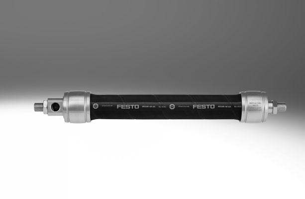
2 Key features Mode of operation Fluidic Muscle is a tensile actuator which mimics the natural movement of a muscle. It consists of contractible tubing and appropriate connectors. The contractible tubing is made up of a rubber diaphragm with a non-crimped fibre made of aramid yarns on the inside. The diaphragm provides a hermetic seal enclosing the operating medium. The yarns serve as a reinforcement and transmit power. When internal pressure is applied, diaphragm extends in the circumferential direction. This creates a tensile force and a contraction motion in the longitudinal direction. The usable tensile force is at its maximum at the start of the contraction and then decreases with the stroke. Force profile and operating range Force Max. force 6000 N The muscle expands lengthways when it is pretensioned by an external force. When pressurised, on the other hand, the muscle contracts, i.e. its length decreases. Max. pressure Core range 0.5% Pneumatic cylinder 9% Max. 25% contraction Areas of application Clamping Vibrating and shaking Pneumatic spring Other High force combined with a small diameter Insensitive to dirt Frictionless movement Hermetically sealed Frequency up to 150 Hz Amplitude/frequency can be adjusted independently of each other Insensitive to dirt Adjustable spring force Frictionless movement Hermetically sealed Easy to handle Positioning using pressure High acceleration of a load 2 Internet: Subject to change 2017/12
3 Key features Fluidic Muscle DMSP with press-fitted connection page 11 In the DMSP, the diaphragm is crimped by means of a sleeve and the adapters are integrated. Nominal length The nominal length of the Fluidic Muscle is defined in the non-pressurised, load-free state. It corresponds to the visible muscle length between the connections ( page 16). Single-acting actuator Sizing examples page 20 In the simplest case, the Fluidic Muscle operates as a single-acting actuator Load = Constant against a mechanical spring or a load. The mechanical spring pretensions the muscle out of its normal position when in the expanded, non-pressurised state. Ideal: 0.5% of nominal length. This operating state is ideal with regard to the technical properties of the Fluidic Muscle: in the unpressurised state, the diaphragm is not compressed. When pressurised, a muscle pretensioned in this way develops maximum force with optimum dynamic characteristics and minimum air consumption. The most effective operating range is provided with contractions below 9%. The smaller the degree of contraction of the Fluidic Muscle, the more effectively it works. The muscle behaves like a spring when there is a change in external force: it follows the application of force. With the Fluidic Muscle, both the pretensioning force of this pneumatic spring and its spring stiffness can be varied. The Fluidic Muscle can be operated as a spring with constant pressure or constant volume. This produces different spring characteristics that enable the spring effect to be matched perfectly to the application. Pressure/volume = Constant -H- Note If the muscle is fed with compressed air and the volume id blocked, the pressure in the muscle can increase significantly when the external force is varied. 2017/12 Subject to change Internet: 3
4 Key features Sizing The simplest and most reliable way to ensure correct sizing is by going through the specialist department Membrane Technologies at Festo. Otherwise, calculation software is available to help you size the Fluidic Muscle. You can also use the force/displacement graphs to make a rough estimate. Sizing of the Fluidic Muscle is explained using examples page 20. -H- Note Do you need technical support? We will be happy to help! Membrane Technologies membrantechnologie@festo.com Efficient range 25% Pmax. 150 Hz 9% PRecommendation = Pmax. 2bar 1 Hz Contraction Operating pressure Motion sequence Frequency -H- Note Kinking, compression or torsion are not permissible lead to failure of the diaphragm Pretensioning by up to 0.5% will prevent kinking and compression Avoid unpressurised state residual pressure up to 0.5 bar 4 Internet: Subject to change 2017/12
5 Application examples Successful areas of application Clamping High force combined with a small diameter Insensitive to dirt Frictionless movement Hermetically sealed Clamping workpieces High forces combined with a small diameter? Not a problem for the Fluidic Muscle. Thanks to its small diameter, it can be integrated and used in the smallest of spaces, e.g. when clamping workpieces. It has an initial force 10 times higher than that of a conventional pneumatic cylinder. Clamping metal sheets The Fluidic Muscle enables large and unwieldy workpieces, such as plates, walls and side covers, to be easily clamped so they can be machined (turning, drilling, milling). This brings out the muscle's outstanding characteristics, such as high force combined with a small diameter, frictionless and thus jerk-free movement, insensitivity to dirt (swarf, abraded particles) and hermetically sealed design. Clamping parts to be joined In joining processes such as those that take place in welding machines, the components to be welded are held in place by the Fluidic Muscle during the joining procedure. Here, too, the muscle can make the most of its high force combined with a small diameter. 2017/12 Subject to change Internet: 5
6 Application examples Successful areas of application Vibrating and shaking Frequency up to 150 Hz Amplitude/frequency can be adjusted independently of each other Insensitive to dirt Distributing When a viscous coating agent is applied to a fixed substance carrier, a vibrating support is required to ensure even distribution over the surface. In the case of strokes of less than 1 mm, the Fluidic Muscle can achieve cycle rates of up to 150 Hz. Conveying The Fluidic Muscle is exceptionally well suited to transporting or aligning parts. Amplitude and cycle rate can be adjusted simply and independently of each other. The muscle's flexibility makes it possible to set the optimum conveying speed for any conveying process. Releasing Hoppers and silos are often susceptible to problems, such as a jamming arch forming during feeding. In practice, discharge aids such as vibrators or knockers are used to prevent such a jam from forming. This function can be implemented with the help of the Fluidic Muscle. The frequency can be set in an infinitely adjustable manner up to 150 Hz, independently of the amplitude. This guarantees a continuous conveying process. 6 Internet: Subject to change 2017/12
7 Application examples Successful areas of application Pneumatic spring Adjustable spring force Frictionless movement Hermetically sealed Easy to handle Stress equalisation In all applications in which threads, films, papers or tapes are transported or wound and unwound using rollers, high stresses develop (peak stresses) and the continuous material being transported can tear. With its adjustable spring force and frictionless movement, the Fluidic Muscle can absorb these stresses. The muscle stands out because of the simple adjustment of the spring strength by means of the pressure and hence by its ease of use. Changes to the process require a change of the mechanical spring and weights. The Fluidic Muscle is an excellent replacement for existing solutions using loads and mechanical springs. Adjustable contact pressure The Fluidic Muscle is exceptionally well suited to pressing on rollers. The contact pressure can be varied using the operating pressure. The design means that components do not become stuck and there are thus no peak forces. The Fluidic Muscle is hermetically sealed and can be disconnected from the compressed air supply. It will nevertheless continue to perform its function. Brakes for tension regulation The spring properties of the Fluidic Muscle make it exceptionally well suited to regulating the thread tension when winding threads. The tension in the threads is always as high as it needs to be for the process in question. This means that the optimum thread tension is always available, leading to better protection of the threads and counteracting wear on all components. 2017/12 Subject to change Internet: 7
8 Application examples Other possible applications Lifting aid Achieving intermediate positions? Very simple, using pressure regulation: the workpieces can be raised or lowered as required by pressurising or exhausting the muscle via a hand lever valve. Muscle lengths up to 9 m facilitate various types of application. Punching Very high cycle rates can be achieved with the muscle, on the one hand because of its low weight and on the other because it has no moving parts (e.g. a piston). The simple design one muscle pretensioned using two springs replaces a complicated toggle lever clamping system using cylinders. Emergency stop device The Fluidic Muscle is setting benchmarks in applications that require fast response times. The emergency stop for rollers demands both speed and a high initial force. This can prevent risks to the operator in the event of malfunctions. 8 Internet: Subject to change 2017/12
9 Product range overview Function Version I.D. Nominal length Lifting force [mm] [mm] [N] Single-acting, pulling Fluidic Muscle with press-fitted connection I.D. [mm] Max. permissible pretensioning Max. permissible contraction Operating pressure [bar] Page/Internet Fluidic Muscle with press-fitted connections 5 1% of nominal length 20% of nominal length % of nominal length 25% of nominal length % of nominal length 25% of nominal length % of nominal length 25% of nominal length /12 Subject to change Internet: 9
10 Peripherals overview Accessories 1 Push-in fittings QSM/QS 2 Quick connectors CK 3 Rod clevis SG 4 Rod eye SGS 5 Coupling pieces KSZ Coupling pieces KSG Description Size Page/Internet For connecting compressed air tubing with standard outside qs diameters For connecting compressed air tubing with standard internal ck diameters Permits swivel motion of the Fluidic Muscle in one plane 19 With spherical bearing To compensate for radial deviations To compensate for radial deviations Internet: Subject to change 2017/12
11 Type codes DMSP 5 500N RM CM Drive function Single-acting, pulling DMSP Fluidic Muscle I.D. [mm] Nominal length [mm] N First connection RM AM Pneumatic connection, radial Pneumatic connection, axial Second connection RM AM CM CF Pneumatic connection, radial Pneumatic connection, axial No pneumatic connection, with male thread No pneumatic connection, with female thread Operating instructions Standard DN Express waiver no operating instructions to be included (already available) Variants DMSP- -RM-CM 1 Radial connection 2 No connection, with male thread 2 DMSP- -RM-RM 1 Radial connection 2 Radial connection 2 DMSP- -RM-AM 1 Radial connection 2 Axial connection DMSP- -AM-CM 1 Axial connection 2 No connection, with male thread 2 DMSP- -AM-AM 1 Axial connection 2 Axial connection 2 DMSP- -RM-CF (DMSP-5) 1 Radial connection 2 No connection, with female thread DMSP- -AM-CF (DMSP-5) 1 Axial connection 2 No connection, with female thread /12 Subject to change Internet: 11

12 Technical data -T- Nominal length mm -N- Size O- Lifting force N General technical data Size Pneumatic connection M3 G1/8 G1/4 G3/8 Design Contracting diaphragm Mode of operation Single-acting, pulling I.D. [mm] Nominal length [mm] Stroke [mm] Max. additional load, freely suspended [kg] Max. permissible pretensioning 1) 1% of nominal length 3% of nominal length 4% of nominal length 5% of nominal length Max. permissible contraction 20% of nominal length 25% of nominal length Max. perm. offset of connections Angle tolerance: 1.0 Parallelism tolerance: ± 0.5 % (up to 400 mm nominal length), 2 mm (from 400 mm nominal length) Type of mounting Via accessories Mounting position Any (an external guide is required if lateral forces occur) 1) The max. pretensioning is achieved when the max. permissible freely suspended payload is attached. Operating and environmental conditions Size Operating pressure [bar] Operating medium Compressed air according to ISO :2010 [7: : ] Note on operating/pilot medium Lubricated operation possible (in which case lubricated operation will always be required) Ambient temperature [ C] Corrosion resistance class CRC 1) 2 Certification TÜV 1) Corrosion resistance class CRC 2 to Festo standard FN Moderate corrosion stress. Indoor applications in which condensation may occur. External visible parts with primarily decorative requirements for the surface and which are in direct contact with the ambient atmosphere typical for industrial applications. Forces [N] at max. permissible operating pressure Size Theoretical force 1) ) For minimum nominal length, the force is reduced by approx. 10%. 12 Internet: Subject to change 2017/12
13 Technical data Weight [g] Size Product weight for 0 m length DMSP- -RM-CM DMSP- -RM-RM DMSP- -RM-AM DMSP- -AM-CM DMSP- -AM-AM DMSP- -RM-CF 7 DMSP- -AM-CF 9 Additional weight per 1 m length Materials Sectional view Fluidic Muscle 1 Nut Galvanised steel 2 Flange Clear anodised wrought aluminium alloy 3 Sleeve Clear anodised wrought aluminium alloy 4 Diaphragm AR, CR Note on materials RoHS-compliant Free of copper and PTFE Contains paint-wetting impairment substances 2017/12 Subject to change Internet: 13
14 Technical data Permissible force F [N] as a function of the contraction h [%] of the nominal length Force/displacement diagrams and sizing ranges The limits specified in the technical data must be complied with when using the Fluidic Muscle. The graphs below illustrate the operating range of the Fluidic Muscle as a function of the diameter, within the limits shown below. Using the graphs 1. The upper limit of the grey area indicates the maximum permissible force. 2. The right limiting curve of the grey area indicates the maximum permissible operating pressure. 3. The right vertical limit of the grey area indicates the maximum permissible contraction. 4. The left limit of the grey area indicates the load limit of the muscle in terms of the maximum permissible pretensioning. Operating range DMSP-5-100N- Sizing examples page 20 0 bar 1 bar 2 bar 3 bar 4 bar 5 bar 6 bar 1 Max. permissible pretensioning 2 Max. permissible contraction 3 Theoretical force (140 N) at max. operating pressure Permissible operating range Operating range DMSP N- Sizing examples page 20 0 bar 1 bar 2 bar 3 bar 4 bar 5 bar 6 bar 7 bar 8 bar 1 Max. permissible pretensioning 2 Max. permissible contraction 3 Theoretical force (630 N) at max. operating pressure Permissible operating range 14 Internet: Subject to change 2017/12
15 Technical data Permissible force F [N] as a function of the contraction h [%] of the nominal length Operating range DMSP N- Sizing examples page 20 0 bar 1 bar 2 bar 3 bar 4 bar 5 bar 6 bar 1 Max. permissible pretensioning 2 Max. permissible contraction 3 Theoretical force (1500 N) at max. operating pressure Permissible operating range Operating range DMSP N- Sizing examples page 20 0 bar 1 bar 2 bar 3 bar 4 bar 5 bar 6 bar 1 Max. permissible pretensioning 2 Max. permissible contraction 3 Theoretical force (6000 N) at max. operating pressure Permissible operating range -H- Note The actual value of the force as a factor of the contraction can vary according to the product characteristics and the ambient conditions present. The deviation can be compensated if the pressure is adapted up to the maximum permissible operating pressure. The simplest and most reliable way to ensure correct sizing is by going through the specialist department Membrane Technologies at Festo. We can take all the crucial parameters for your application into consideration. We will be happy to help! Membrane Technologies membrantechnologie@festo.com 2017/12 Subject to change Internet: 15
16 Technical data Dimensions DMSP- -RM-CM pneumatic connection, radial no connection, with male thread Download CAD data 1 Installed length 2 Nominal length DMSP- -RM-RM pneumatic connection, radial pneumatic connection, radial 1 Installed length 2 Nominal length DMSP- -AM-RM pneumatic connection, axial pneumatic connection, radial 1 Installed length 2 Nominal length DMSP- -AM-CM pneumatic connection, axial no connection, with male thread 1 Installed length 2 Nominal length Size D1 D2 D3 EE 2) Ln 1) L1 L2 max. min. max. RM-CM RM-RM AM-RM AM-CM 5 11 M6 M8 M M8 M16x1.5 G1/ M10x1.25 M20x1.5 G1/ M16x1.5 M30x1.5 G3/ Size L3 L4 L5 L6 L7 ß1 2) ß2 2) ß3 2) ß4 ß ) Tolerance 100 mm ±1 mm, mm ±1%, 400 mm ±4 mm. 2) Parallel orientation of the spanner flats on the left and right connection side can lead to deviations (for production reasons). 16 Internet: Subject to change 2017/12
17 Technical data Dimensions DMSP- -AM-AM pneumatic connection, axial pneumatic connection, axial Download CAD data 1 Installed length 2 Nominal length DMSP- -RM-CF pneumatic connection, radial no connection, with female thread 1 Installed length 2 Nominal length DMSP- -AM-CF pneumatic connection, axial no connection, with female thread 1 Installed length 2 Nominal length Size D1 D2 D3 EE EE1 Ln 1) L1 L2 max. min. max. AM-AM RM-CF AM-CF 5 11 M6 M8 M3 M M8 M16x1.5 G1/ M10x1.25 M20x1.5 G1/ M16x1.5 M30x1.5 G3/ Size L4 L5 L6 L7 L8 ß1 2) ß3 2) ß4 ß5 ß ) Tolerance 100 mm ±1 mm, mm ±1%, 400 mm ±4 mm. 2) Parallel orientation of the spanner flats on the left and right connection side can lead to deviations (for production reasons). Diameter expansion at maximum contraction Size [mm] /12 Subject to change Internet: 17
18 Ordering data Modular products Ordering table Size Conditions 0M Module no Code Entry code Function Fluidic Muscle with press-fitted connection DMSP DMSP Size [mm] Nominal length [mm] N - N First connection Radial, male thread -RM Mounting thread/supply port M6 / M3 M8 / G1/8 M10x1.25 / G1/4 M16x1.5 / G3/8 Axial, male thread -AM Mounting thread/supply port M8 / M3 M16x1.5 / G1/8 M20x1.5 / G1/4 M30x1.5 / G3/8 Second connection Closed, male thread -CM Mounting thread M6 M8 M10x1.25 M16x1.5 Closed, female -CF thread Mounting thread M4 Radial, male thread -RM Mounting thread/supply port M6 / M3 M8 / G1/8 M10x1.25 / G1/4 M16x1.5 / G3/8 Axial, male thread -AM Mounting thread/supply port M8 / M3 M16x1.5 / G1/8 M20x1.5 / G1/4 M30x1.5 / G3/8 Operating instructions Standard Express waiver no operating instructions to be included (already available) -DN M Mandatory data Transfer order code DMSP N 18 Internet: Subject to change 2017/12
19 Accessories Ordering data Technical data Internet: piston-rod attachment Description For size Part No. Type Description For size Part No. Type Rod eye SGS Coupling piece KSG SGS-M SGS-M SGS-M10x1, KSG-M10x1, SGS-M16x1,5 1) KSG-M16x1,5 Rod clevis SG Coupling piece KSZ SG-M KSZ-M SG-M KSZ-M SG-M10x1, KSZ-M10x1, SG-M16x1,5 1) KSZ-M16x1,5 -H- Note 1) If there is a dynamic load on the DMSP40, the technical data will be subject to restrictions because of the accessories. Fundamentals: rated load, friction torque where μ = 0.2: Endurance limit at 6000 N: 1 million load cycles (higher values on request) Endurance limit at 4000 N: 10 million load cycles 2017/12 Subject to change Internet: 19
 of the Fluidic Muscle needs to be determined.")
20 Sizing Example 1 Lifting a constant load The muscle is to be used to lift a constant load of 60 kg, free of forces, from a supporting surface, and raise it a distance of 10 mm. The compressed air supply provides a maximum of 6 bar. The size (diameter and nominal length) of the Fluidic Muscle needs to be determined. -H- Note The simplest and most reliable way to ensure correct sizing is by going through the specialist department Membrane Technologies at Festo. We can take all the crucial parameters for your application into consideration. We will be happy to help! Membrane Technologies membrantechnologie@festo.com General conditions Values Required force at rest [N] 0 Required stroke [mm] 10 Required force in contracted state [N] Approx. 600 Max. possible operating pressure [bar] 6 Choice of parameters Efficient range 25% Pmax. 150 Hz 9% PRecommendation = Pmax. 2bar 1 Hz Contraction Operating pressure Motion sequence Frequency Solution Steps Selection Input parameters Result Step 1: Calculation of nominal length (stroke 10 mm/contraction 5%) 200 mm Choice of operating pressure (p max. 2 bar) 4 bar Step 2: Input of values into engineering tool Intermediate result for force Nominal length: Stroke: Operating pressure: Size: 200 mm 10 mm 4 bar 20 mm 674 N Step 3: Adjustment of input values Operating pressure: 3.7 bar Result: 609 N 20 Internet: Subject to change 2017/12
21 Sizing Example 2 Use as a tension spring In this example, the muscle is to be used as a tension spring. The size (diameter and nominal length) of the Fluidic Muscle needs to be determined. -H- Note The simplest and most reliable way to ensure correct sizing is by going through the specialist department Membrane Technologies at Festo. We can take all the crucial parameters for your application into consideration. We will be happy to help! Membrane Technologies membrantechnologie@de.festo.com If you are determining the size yourself, you must follow this recommendation: contraction 9%, operating pressure p Recommendation = p max. 2 bar, see choice of parameters General conditions Values Required force in extended state [N] 2000 Required force in contracted state [N] 1000 Required stroke (spring length) [mm] 50 Operating pressure [bar] 2 Solution Step 1 Determine the required muscle size Step 2 Enter load point 1 Step 3 Enter load point 2 Step 4 Read the length change Step 5 Calculate the nominal length Step 6 Result Determine the most suitable muscle diameter on the basis of the required force. Load point 1 is entered into the force/ displacement diagram for the DMSP-40-. Load point 2 is entered into the force/ displacement diagram. The change in the length of the muscle is read off between the load points on the X-axis (contraction in %). The required nominal muscle length for a stroke of 50 mm is obtained by dividing by the contraction in %. The nominal length of the muscle to be ordered is 575 mm. The required force is 2000 N, therefore a DMSP-40- is selected. Force F = 2000 N Pressure p = 2 bar Force F = 1000 N Pressure p = 2 bar Result: 8.7% contraction. Result: 50 mm / 8.7% ~ 575 mm. For use as a tension spring with a force of 2000 N and a spring travel of 50 mm, a DMSP N- is required. 0 bar 1 bar 2 bar 3 bar 4 bar 5 bar 6 bar 1 Load point 1 2 Load point 2 3 Change in length = 8.7% 2017/12 Subject to change Internet: 21
Fluidic Muscle DMSP/MAS
 Fluidic Muscle DMSP/MAS Fluidic Muscle DMSP/MAS Key features Mode of operation Fluidic Muscle is a tensile actuator which mimics the natural movement of a muscle. It consists of contractible tubing and
Bellows actuator EB Key features
 Bellows actuator B Bellows actuator B Key features Key features Suitable for use in harsh, dusty ambient conditions Can be used under water Sturdy design Large forces range from 1 50 KN Low installation
Proportional pressure regulators VPPE
 Proportional pressure regulators VPPE Proportional pressure regulators VPPE Product range overview Function Version Pneumatic connection Proportional pressure regulator Nominal size for pressurisation/
Parallel grippers HGPM, micro
 Key features G6: G8: G9: stroke compensation clamping spigot flange mounting At a glance Compact, handy design With open or closed gripper jaws Versatility thanks to externally adaptable gripper fingers
Hand slide valves W/VBOH
 Hand slide valves W/VBOH Hand slide valves W/VBOH Product range overview Version Valve function Version Type Pneumatic connection 1 Pneumatic connection 2 qnn Page/ Internet [l/min] Hand slide valves 3/2-way,
Precision pressure regulators LRP/LRPS
 Precision pressure regulators LRP/LRPS q/w Worldwide: Superb: Easy: Festo core product range Covers 80% of your automation tasks Always in stock Festo quality at an attractive price Reduces procurement
Heavy-duty three-point grippers HGDT
 Key features At a glance The force generated by the linear motion is translated into the gripper jaw movement via a force-guided triple wedge mechanism. This also guarantees synchronous movement of the
Hand lever valves VHER
 Hand lever valves VHER Hand lever valves VHER Key features Powerful Flexible Practical -M- Flow 170 3800 l/min 4/3-way valve mid-position closed mid-position exhausted mid-position pressurised Connections:
Micro grippers HGPM/HGWM
 HGPM/HGWM Miniaturised and optimised for assembly tasks Versatile 2004/10 Subject to change Products 2004/2005 1 / 1 HGPM/HGWM Key features HGWM HGPM 1 2 3 4 1 2 3 4 System product for handling and assembly
Push-in fittings CRQS, stainless steel
 Features Application Effortless selection of the right fitting. Festo offers a secure solution for every connection. The convenient push-in fitting system includes well over 1000 types of standard and
Valves, manually operated
 Valves, manually operated Valves, manually operated Key features VHEM-P K/O-3-PK-3 H-3-¼-B KH/O-3-PK3 TH/O-3-PK3 F-3-¼-B Innovative Versatile Reliable Easy to mount Small and compact for a wide range of
Valves, manually operated
 Valves, manually operated Valves, manually operated Key features VHEM-P K/O-3-PK-3 H-3-¼-B KH/O-3-PK3 TH/O-3-PK3 VHEM-L F-3-¼-B Innovative Versatile Reliable Easy to mount Small and compact for a wide
Parallel grippers HGPM, micro
 Key features G6: G8: G9: with stroke compensation with clamping spigot with flange mounting At a glance Compact, handy design With open or closed gripper jaws Versatility thanks to externally adaptable
Solenoid valves VZWF, force pilot operated
 Key features and overview Function Normally closed solenoid valve with diaphragm and forced lifting. When the solenoid is energised, the differential pressure from the secondary side of the diaphragm is
Angle grippers HGWM, micro
 Key features G6: G7: G8: with stroke compensation with male thread with clamping spigot At a glance Compact, handy design With open or closed gripper jaws Versatility thanks to externally adaptable gripper
Push-in fittings NPQH
 Key features Application Effortless selection of the right fitting. Festo offers a secure solution for every connection. The convenient push-in fitting system includes well over 1000 types of standard
Push-in fittings NPQH
 Key features Application Effortless selection of the right fitting. Quick Star offers a secure solution for every connection. The convenient push-in fitting system includes well over 1000 types of standard
Hand slide valves W/VBOH
 Hand slide valves W/VBOH Hand slide valves W/VBOH Product range overview Version Valve function Version Type Pneumatic connection 1 Pneumatic connection 2 qnn Page/ Internet [l/min] Hand slide valves 3/2-way,
Pressure boosters DPA
 Key features Function The pressure booster is a twin-piston pressure intensifier intended solely for compressing air. When the DPA is pressurised with compressed air, integrated non-return valves automatically
Bernoulli grippers OGGB
 Key features General Purpose Benefits Applications The Bernoulli gripper OGGB is ideally suited to transporting thin, extremely delicate and brittle workpieces. Minimised workpiece contact, gentle workpiece
Gripping rotary modules
 Gripping rotary modules Gripping rotary modules GRIPPING ROTARY MODULES Series Size Page Gripping rotary modules RP 314 RP 1212 318 RP 1216 322 RP 1520 326 RP 2120 330 RP 2128 334 RC 338 RC 1212 342 RC
Push-in fittings QB, NPT
 General technical data Connecting thread UNF NPT Size Standard Design Push-pull principle Mounting position An Tpe of seal on threaded plug Sealing ring Coating Operating and environmental conditions Operating
Proportional pressure regulators VPPM
 Key features LED indicators Control elements Display Plug socket with cable Venting at both ends Manifold block Sub-base valve Assembly repositionable by 180 In-line valve H-rail mounting Compressed air
Cost effective. Smooth. Reliable. LOG Internal Hole Gripper
 LOG Cost effective. Smooth. Reliable. LOG Internal Hole Gripper Light gripper made of very resistant polyamide with closed diaphragm system Field of Application Particularly suited to highly dynamic applications
Pneumatic Grippers Swivel Modules
 Pneumatic Grippers Swivel Modules Pneumatic Grippers Swivel Modules ROTARY GRIPPERS MODULES Series Size Page GSM 748 Parallel Grippers GSM-P 750 GSM-P 32 754 GSM-P 40 760 GSM-P 50 766 GSM-P 64 772 Centric
Description Total stroke Maximum Recommended Page in mm gripping force in N workpiece weight in kg
 Overview parallel gripper Description Total stroke Maximum Recommended Page in mm gripping force in N workpiece weight in kg Version 1 2 1 2 1 2 RRP-A 64 12 6 240 450 1,2 2,2 26 80 16 8 380 700 1.9 3.5
Parallel grippers HGPT-B, heavy-duty
 Key features Advantages compared with the parallel gripper HGPT Space-optimised: Choice of shorter housing without gripping force retention or longer housing with gripping force retention Increased gripping
High flow rate. Cost effective. Compliant. Gripper with GSW-B Shaft Interface and Compensation Unit
 GSW-B-AGE High flow rate. Cost effective. Compliant. Gripper with GSW-B Shaft Interface and Compensation Unit PGN-plus / PZN-plus universal gripper with shaft interface GSW-B and AGE compensation unit
Pneumatic Gripping Modules. Pneumatic 2-Finger Radial Grippers
 Pneumatic Gripping Modules Pneumatic 2-Finger Radial Grippers Pneumatic Gripping Modules Pneumatic 2-Finger Radial Grippers 2-FINGER RADIAL GRIPPERS Series Size Page Universal Grippers GWB 676 GWB 34 680
Technical Data Sheet TI-F50 Locking Units series KFH
 English translation of German original Locking Units series KF Further important practical advice is given in Operating Manual BA-F50., Rod diameter 18 mm 50 mm øz 8 L 2 6 x 6 0 min. 4x30 KF 18 to KF 32,
PFH. Application example. Pneumatic 2-Finger Parallel Gripper Long-stroke Gripper. Weight 2.65 kg 12.6 kg. Gripping force 630 N 2950 N
 PFH www.comoso.com Sizes 30 50 Weight 2.65 kg 12.6 kg Gripping force 630 N 2950 N Stroke per finger 30 mm 100 mm Workpiece weight 3.15 kg 13 kg Application example Assembly unit for intermediate sleeves
Adaptive gripper fingers DHAS
 Features At a glance Adaptive gripper fingers for smooth and flexible gripping, with the Fin Ray Effect derived from the movement of a fish s tail fin. Two flexible bands, which meet at the top like a
Gripping modules Pneumatic 2-finger parallel gripper Long-stroke gripper for small components Gripping force 120 N..
 GM Sizes 85.. 205 Mass 0.48 kg.. 2.7 kg 120 N.. 595 N Stroke per finger 16 mm.. 30 mm Workpiece weight, force-fit gripping Up to 2.3 kg Application example 3 5 3 4 2 5 2 1 1 Pneumatic double pick & place
Exhaust air flow control valves
 Exhaust air flow control valves Exhaust air flow control valves Product range overview Function Exhaust air flow control valves are screwed into the exhaust controls of control valves or drives. They enable
Push-in fittings CQ, for push-fit piping systems
 Key features General information Suitable for polyamide pipes PQ-PA and aluminium pipes PQ-AL O.D. 12, 15, 18, 22 and 28 mm Internet: pq Suitable for polyamide tubing PAN and polyurethane tubing PUN O.D.
PWG-S. Application example. Pneumatic 2-Finger Angular Gripper Universal Gripper. Sizes. Gripping moment 5.98 Nm Nm. Weight 0.21 kg 1.
 PWG-S Sizes 40 80 Weight 0.21 kg 1.2 kg Gripping moment 5.98 Nm 50.82 Nm Angle per jaw 20 Workpiece weight 1.1 kg 4.8 kg Application example Rotating/gripping combination for flexible handling of sheet
Reliable. Fully encapsulated. Loadable. DPG-plus Sealed Gripper
 DPG-plus Reliable. Fully encapsulated. Loadable. DPG-plus Sealed Gripper Despite the high moment load of the base jaws, this sealed 2-finger parallel gripper conforms to the IP67 requirements and does
KM/ Stainless steel air bellows Single acting Ø 220 to 400 mm
 KM/ Stainless steel air bellows Single acting Ø to mm Stainless steel end plates Frictionless operation No maintenance or lubrication Ideal for short stroke, high-force applications High isolation level
Pressure relief valve DHV 716 set range: 0,5-10,0 bar
 Pressure relief valve DHV 7 set range: 0,5-0,0 bar Advantage pressure setting possible at any time, also during operation optimum monitoring valves high reproducibility of the set pressure high level of
GWB Pneumatic 2-Finger Radial Gripper Universal Gripper Sizes Weight Gripping moment Opening angle per finger Workpiece weight
 GWB Sizes 34.. 100 Weight 0.14 kg.. 3.5 kg Gripping moment 2.1 Nm.. 127 Nm Opening angle per finger 10.. 90 Workpiece weight 0.3 kg.. 6.0 kg Application example Rotating/gripping combination for handling
Translation of the original Operating Instructions for HKS rubber compensators
 Because of their flexible elements and mechanisms, HKS rubber compensators are susceptible to damage of all types and adverse loads in operation. For reliable operation of a compensator and, thus, the
Gebrüder Dreher Drehteile & Gasfedern GmbH
 Gebrüder Dreher Drehteile & Gasfedern GmbH Product Line Gas Springs Introduction Calculation We are an owner-run family business with a success story that began some 70 years ago with the production of
Push-in fittings CRQS, stainless steel
 Features Application Effortless selection of the right fitting. Festo offers a secure solution for every connection. The convenient push-in fitting system includes well over 1000 types of standard and
PFH. Application example. Pneumatic 2-Finger Parallel Grippers Long-stroke Grippers. Sizes Gripping force 510 N N
 PFH Sizes 30.. 50 Weight 2.65 kg.. 9.7 kg Gripping force 510 N.. 2650 N Stroke per finger 30 mm.. 50 mm Workpiece weight 2.55 kg.. 11.5 kg Application example Assembly unit for intermediate sleeves in
PSH. Application example. Pneumatic 2-Finger Parallel Gripper Long-stroke Gripper. Stroke per finger 14 mm.. 64 mm. Sizes
 PSH Sizes 22.. 52 Weight 0.77 kg.. 8.05 kg 320 N.. 1760 N Stroke per finger 14 mm.. 64 mm Workpiece weight 1.60 kg.. 8.80 kg Application example Rapid loading and unloading unit on a swivel head base.
KM/31000 (Stainless steel end plates) Air bellows, single acting
 Air bellows, single acting") KM/ (Stainless steel end plates) > > Ø... / inch (... mm) > > Very easy to install no alignment problems > > Almost frictionless operation > > No maintenance or lubrication > > Typical applications; actuator,
KM/ (Stainless steel end plates) > > Ø... / inch (... mm) > > Very easy to install no alignment problems > > Almost frictionless operation > > No maintenance or lubrication > > Typical applications; actuator,
Components for air preparation and pressure adjustment. OUT port position ( ) connected Rear side. of IN port. Air tank. directly.
 connected Rear side. of IN port. Air tank. directly.") Components preparation and pressure adjustment ABP Overview ABP is a component that enables boosting by s only up to twice primary pressure (.0MPa max.) in combination with using air tank but not using
Components preparation and pressure adjustment ABP Overview ABP is a component that enables boosting by s only up to twice primary pressure (.0MPa max.) in combination with using air tank but not using
PGN. Application example. Pneumatic 2-Finger Parallel Grippers Universal Grippers. Gripping force 100 N N. Sizes
 PGN Sizes 50.. 380 Weight 0.125 kg.. 28.0 kg Gripping force 100 N.. 15100 N Stroke per finger 2 mm.. 45 mm Force-fit gripping 0.5 kg.. 75.0 kg Application example Horizontal turning station with 180 reorientation
DPZ-plus. Application example. Pneumatic 3-Finger Centric Grippers Sealed Grippers. Gripping force 520 N N. Sizes
 DPZ-plus Sizes 64.. 200 Weight 0.62 kg.. 20.1 kg Gripping force 520 N.. 16800 N Stroke per finger 3 mm.. 25 mm Workpiece weight 2.6 kg.. 60.0 kg Application example Insertion tool for assembling small
SPG. Application example. Pneumatic 2-Finger Parallel Gripper Heavy-load Gripper. Weight 35 kg. Stroke per finger 100 mm.
 SPG Size 100 Weight 35 kg 10,000 N Stroke per finger 100 mm Workpiece weight 50 kg Application example Gripper unit for heavy V8 engine blocks. SPG 100 2-Finger Heavy-load Gripper 446 www.schunk.com SPG
PSH (inch version) Application example. Pneumatic 2-Finger Parallel Grippers Long-stroke Grippers. Stroke per finger 14 mm.. 64 mm. Sizes 22..
 Application example. Pneumatic 2-Finger Parallel Grippers Long-stroke Grippers. Stroke per finger 14 mm.. 64 mm. Sizes 22..") PSH (inch version) Sizes 22.. 52 Weight 0.77 kg.. 8.05 kg Gripping force 320 N.. 1760 N Stroke per finger 14 mm.. 64 mm Workpiece weight 1.60 kg.. 8.80 kg Application example Rapid loading and unloading
PSH (inch version) Sizes 22.. 52 Weight 0.77 kg.. 8.05 kg Gripping force 320 N.. 1760 N Stroke per finger 14 mm.. 64 mm Workpiece weight 1.60 kg.. 8.80 kg Application example Rapid loading and unloading
Self-priming makes priming unnecessary Exhausts the air inside the suction pipe to suck up liquid. Air operated type.
 Process Pump Series 3/5 Automatically Operated Type (Internal Switching Type)/Air Operated Type (External Switching Type) High abrasion resistance and low particle generation o sliding parts in wetted
250 (9.84) 170 (6.69) 225 (8.85) 75 (2.95) 300 (11.81)
 170 (6.69) 225 (8.85) 75 (2.95) 300 (11.81)") Air bellows, single acting Ø... / inch Suitable for applications on rail vehicels Almost frictionless operation No maintenance or lubrication Weather/corrosion resistant metal parts Approvals for fire
Air bellows, single acting Ø... / inch Suitable for applications on rail vehicels Almost frictionless operation No maintenance or lubrication Weather/corrosion resistant metal parts Approvals for fire
pneumatic power clamps
 pneumatic power clamps Features Király Trading KFT H-1151 Budapest Mogyoród útja 12-14 E-mail:_agi@kiralytrading.hu Your requirements Power element of machines, tools and devices for the following applications:
Pressure Reducing Valve DMV 750 set range: bar
 Pressure Reducing Valve DMV 750 set range:.0-6.0 bar Advantage pressure setting possible at any time, also during operation hermetically sealed by valve diaphragm high level of operating safety and long
Push-in fittings QB, NPT
 General technical data Connecting thread UNF10-32 NPT1/8-27 NPT1/4-18 NPT3/8-18 NPT1/2-14 Size Standard Design Push-pull principle Mounting position An Tpe of seal on threaded plug Sealing ring Coating
Single and double acting, magnetic, self-centering Bores: ø 16, 20, 25, 32, 40 mm
 > Series CGPT self-centering parallel grippers with T-guide Series CGPT self-centering parallel grippers with T-guide Single and double acting, magnetic, self-centering Bores: ø 6, 20, 25, 32, 40 mm New
MPG-plus. Application example. Pneumatic 2-Finger Parallel Gripper Gripper for small components. Gripping force 38 N 175 N. Sizes
 MPG-plus Sizes 25 40 Weight 0.06 kg 0.24 kg Gripping force 38 N 175 N Stroke per finger 3 mm 6 mm Workpiece weight 0.19 kg 0.7 kg Application example Pneumatically driven, dual-axis pick-and-place machine
K0709 Quick-fit couplings
 Joints 1067 K0709 Quick-fit couplings with radial offset compensation external thread D1 SW SW1 application example: X max. D D 3 4 internal thread SW 3 4 2 SW1 D D Coupling part and claw in steel. Nut
PZN-plus. Application example. Pneumatic 3-Finger Centric Gripper Universal Gripper. Sizes Gripping force 580 N..
 PZN-plus Sizes 40.. 300 Weight 0.43 kg.. 43.5 kg Gripping force 580 N.. 38000 N Stroke per finger 3 mm.. 35 mm Workpiece weight 2.9 kg.. 190 kg Application example Insertion tool for assembling small to
VPPL VARIABLE DISPLACEMENT AXIAL-PISTON PUMPS FOR INTERMEDIATE PRESSURE SERIES 10
 / ED VPPL VARIABLE DISPLACEMENT AXIAL-PISTON PUMPS FOR INTERMEDIATE PRESSURE SERIES OPERATING PRINCIPLE The VPPL are variable displacement axial-piston pumps with variable swash plate, suitable for applications
Pressure relief valve DHV 712 DN 65-80: 0,5-10 bar, DN : 0,3-4 bar, DN 100: 0,5-6 bar
 Pressure relief valve DHV 7 DN 5-80: 0,5-0 bar, DN 5-00: 0, - bar, DN 00: 0,5 - bar Advantage for high pressure stability reliable reduction of pressure peaks and pulsations pressure setting possible at
LGP. Application example. Pneumatic 2-Finger Parallel Gripper Universal Gripper. Sizes. Gripping force 26 N 1090 N. Weight 0.03 kg 1.
 LGP Sizes 8 4 Weight.3 kg 1.6 kg 26 N 19 N Stroke per finger 2 mm 13 mm Workpiece weight.13 kg 4.2 kg Application example Pneumatic double transfer unit 2-Finger Parallel Gripper LGP Universal Rotary Actuator
Electropneumatic Positioner and Pneumatic Positioner Type 3760 JIS
 Electropneumatic Positioner and Pneumatic Positioner Type 3760 Application Single-acting positioners for direct attachment to pneumatic control valves. Supplied with an electric input signal of 4 to 20
VSR modulating valves with membrane actuator
 Modulating valves are used in process technology to control process parameters such as temperature, pressure or flow when handling liquid and gaseous media. uth's team of design and process engineers have
pipe connectors. General description of pipe connectors Development/Design Purpose Versions
 Pipe connectors General description of pipe connectors 1 STFLEX pipe connectors, just like STFLEX rubber expansion joints, have been used for more than years as the preferred connection elements in appliance
G R I P P E R S English edition 10/2012
 GRIPPERS English edition 10/2012 76 GRIPPERS CONTENTS PRECISION PARALLEL GRIPPERS 78-93 PRECISION PARALLEL MINI GRIPPERS 96 109 UNIVERSAL PARALLEL GRIPPERS 112 121 LONG-STROKE GRIPPERS 122 131 77 UNIVERSAL
valves and actuators SUBSEA ACTUATION
 valves and actuators SUBSEA ACTUATION 100 C 55 M 20 Y 0 K 0 C 0 M 0 Y 80 K subsea PetrolValves offers a complete single-source integrated solution for manual or actuated high integrity ball, check, slab
Grippers with Spindle Interface
 Weight 0.8 kg.. 3.9 kg Gripping force 70 N.. 1200 N Stroke per finger 4 mm.. 10 mm Layout of the work area in the machining center Example of a handling and machining sequence: 1. Gripper removes blank
Pressure relief valve DHV 725 set range: 0,2-10,0 bar
 Pressure relief valve DHV 75 set range: 0, - 0,0 bar Advantage pressure setting possible at any time, also during operation optimum monitoring valves high reproducibility of the set pressure high level
Displacement 12, , Maximum flow rate (at 1450 rpm) bar.
 bar.") 00/07 ED PVD VARIABLE DISPLACEMENT VANE PUMPS SERIES 0 OPERATING PRINCIPLE The PVD pumps are variable displacement vane pumps with a mechanical type of pressure compensator. They allow instantaneous adjustment
00/07 ED PVD VARIABLE DISPLACEMENT VANE PUMPS SERIES 0 OPERATING PRINCIPLE The PVD pumps are variable displacement vane pumps with a mechanical type of pressure compensator. They allow instantaneous adjustment
Pressure Relief Valve DHV 718
 Advantages frictionless components low maintenance low pressure increase up to fully opened valve constant low vibration controlling hermetically sealed by diaphragm for oscillating pumps for viscous media
Technical Information TI-S10 Safety Locks. 2 Function. Contents
 English translation of German original TI-S1 Safety Locks high holding force by self-reinforcing clamping hydraulic or pneumatic actuation for static loads For further information on technical data please
Corrugated Hose Loop Calculations
 Corrugated Hose Loop Calculations The loop installation is one of the most common application for metal hoses. It allows the flexible hose assembly to work properly. Care must always be exercised to ensure
Pressure Reducing Valve DMV 755
 Pressure Reducing Valve DMV 755 Nominal size DN 10 50 Nominal size 3/8 2 Nominal pressure PN 10 bar Features pressure setting range 1 to 9 bar control valve for reliable reduction of system pressures to
Precision one-way flow control valves GRP
 Product range overview and type codes Product range overview Version Valve function Version Type Connection direction Precision one-way flow control valve Metal One-way flow control function Pneumatic
Materials : Dichromate zinc plated steel flanges
 Size : Ends : Min Temperature : Max Temperature : DN 25 to 300 Flanges PN10/16-35 C + 130 C Max Pressure : 16 Bars up to DN150, 10 bars over Specifications : Absorb vibrations and noise Linear and angular
Process Pump Automatically Operated Type (Internal Switching Type) Air Operated Type (External Switching Type) How to Order
 Air Operated Type (External Switching Type) How to Order") Process Pump /5 Series Automatically Operated Type (Internal Switching Type)/Air Operated Type (External Switching Type) High abrasion resistance and low particle generation o sliding parts in wetted areas.
Process Pump /5 Series Automatically Operated Type (Internal Switching Type)/Air Operated Type (External Switching Type) High abrasion resistance and low particle generation o sliding parts in wetted areas.
09 - Choosing /sizing a cylinder and valve
 - Choosing /sizing a cylinder and valve - Pipe flow resistence - Valve sizing - Cylinder sizing LII PIPE FLOW RESISTENCE Flow rate Qn Flow rate is calculated as the volume at normal conditions ( atmospheric
Unit 24: Applications of Pneumatics and Hydraulics
 Unit 24: Applications of Pneumatics and Hydraulics Unit code: J/601/1496 QCF level: 4 Credit value: 15 OUTCOME 2 TUTORIAL 9 ACCUMULATORS The material needed for outcome 2 is very extensive so there are
Pressure Reducing Valve DMV 755 set range: 1,0-9,0 bar
 Pressure Reducing Valve DMV 755 set range:,0-9,0 bar Advantage pressure setting possible at any time, also during operation high reproducibility of the set pressure high level of operating safety and long
Pressure independent control valve (PICV) FLOWMATIC
 FLOWMATIC") Pressure independent control valve (PICV) FLOWMATIC 145 series FM 21654 003 01262/19 GB replaces dp 01262/17 GB Function The pressure independent control valve is a device composed of an automatic flow
Pressure independent control valve (PICV) FLOWMATIC 145 series FM 21654 003 01262/19 GB replaces dp 01262/17 GB Function The pressure independent control valve is a device composed of an automatic flow
Ball valve HKSF-W100. Ball valve HKSF-W100. RMA Kehl GmbH & Co. KG Oststrasse 17 D Kehl / Germany
 Ball valve HKSF-W100 RMA Kehl GmbH & Co. KG Oststrasse 17 D-77694 Kehl / Germany info@rma-kehl.de www.rma-armaturen.de 1 Design Features: RMA-ball valves type HKSF-W are fully welded and completely maintenance-free
SPCH/ Blowing block
 > > for linear stretch blow moulding machines > > Compact and safe design > > Best suited for PET bottles up to litres, depending on cycle time Technical features Medium: Compressed air (purity class 3..3
// ADapters GUIDelines
 // ADapters GUIDelines ADAPTER SELECTION Selection of an appropriate ALFAGOMMA adapter for a given application depends on the fluid system operating parameters listed below and the tube material and wall
Technical Data Sheet TI-F52 Locking Unit KFHL Certified by Lloyd s Register
 English translation of German original TI-F52 Locking Unit KFHL Certified by Lloyd s Register For a detailed functional description refer to Technical Information TI-F10. Further important practical advice
![[Instruments for vacuum measurement, checking and adjustment] 3](/thumbs/94/121874202.jpg "[Instruments for vacuum measurement, checking and adjustment] 3")
Pressure and Flow Control Valves DBGM, German and European Patents
 Pressure and Flow Control Valves DBGM, German and European Patents Absolutely Reliable Pressure and Flow Control In water mains of sizes DN 50 to DN 150, ERHARD Control Valves in straight or angle pattern
Sizes Weight Gripping force Stroke per finger Workpiece weight Pieces : kg N mm kg
 MPG-plus Sizes Weight Gripping force Stroke per finger Workpiece weight Pieces : 7 0.06.. 0.63 kg 25.. 350 N 1.5.. 10 mm 0.19.. 1.25 kg Application example Pneumatically driven, dual-axis pick-andplace
HUPF Series DESCRIPTION APPLICATION INSTRUCTION SHEET GAS PRESSURE REGULATOR WITH INCORPORATED FILTER EN1C-0003NL05 R1205.
 HUPF Series GAS PRESSURE REGULATOR WITH INCORPORATED FILTER INSTRUCTION SHEET DESCRIPTION Spring-loaded regulator with inlet pressure compensation and zero shut-off. The outlet pressure is kept constant
Fixed Displacement Plug-In Motor A2FE
 www.phphyds.com Series 6, axial tapered piston, bent axis design for mounting in mechanical gearboxes Sizes 28...355 Nom. Pressure up to 400 bar Peak Pressure up to 450 bar he fixed displacement plug-in
Basic Pneumatics. Module 8: Pressure control valves. Academic Services PREPARED BY. April 2012
 Basic Pneumatics Module 8: Pressure control valves PREPARED BY Academic Services April 2012 Applied Technology High Schools, 2012 Module 8: Pressure control valves Module Objectives After the completion
GUKO FDA. einfach. gut. beraten.
 GUKO FDA Size : Ends : Min Temperature : Max Temperature : DN 25 to 300 Flanges PN10/16-25 C + 90 C Max Pressure : 16 Bars Specifications : Absorb vibrations and noise Linear and angular compansion Inner
Series CGZT three-jaw grippers with T-guide
 Series CGZT three-jaw grippers with T-guide New Single and double acting, magnetic, self-centering Sizes: 40, 50, 64, 80, 100, 125, 160 mm The new Series CGZT pneumatic grippers, thanks to the use of a
Tapered Roller Bearings in X-life quality Customer Information. Business Unit TRB Schweinfurt, 2013
 Tapered Roller Bearings in X-life quality Customer Information Business Unit TRB Schweinfurt, 2013 X-life roll-out BU TRB Agenda Tapered Roller Bearings in X-life quality 1 2 3 4 X-life what is it? X-life
LGP Pneumatic 2-Finger Parallel Gripper Universal Gripper Sizes Weight Gripping force Stroke per finger Workpiece weight
 LGP Sizes 8.. 4 Weight.34 kg.. 1.5 kg 27 N.. 19 N Stroke per finger 2 mm.. 13 mm Workpiece weight.65 kg.. 2.5 kg Application example pneumatic double transfer unit 2-Finger Parallel Gripper LGP 2 Universal
Materials : Dichromate zinc plated steel flanges or AISI 316
 Size : Ends : Min Temperature : Max Temperature : DN 25 to 300 Flanges PN10/16-35 C + 90 C Max Pressure : 16 Bars (10 bars at 90 C) Specifications : Absorb vibrations and noise Linear and angular compansion
Electropneumatic Positioner and Pneumatic Positioner Type 3760 JIS
 Electropneumatic Positioner and Pneumatic Positioner Type 3760 Application Single-acting positioners for direct attachment to pneumatic control valves. An electric standardized signal of 4 to 20 ma or
LGR. Application example. Pneumatic 2-Finger Radial Gripper Universal Gripper. Sizes. Gripping moment 0.3 Nm 15 Nm. Weight 0.07 kg 1.
 LGR Sizes 10 40 Weight 0.07 kg 1.27 kg Gripping moment 0.3 Nm 15 Nm Angle per jaw 90 Workpiece weight 0.07 kg 1066 kg Application example Rotational adjustment for reorientation of workpieces 2-Finger
Product Information. Tolerance compensation unit TCU-Z
 Product Information TCU-Z TCU-Z Compact. Flexible. Productive. TCU-Z tolerance compensation unit The TCU is compensated on the basis of elastomers that compensate in all three directions, enabling them