AV-S Ventilator. Service Manual. Partnership for Life. Remote Display Module and Interface for use with A200SP Absorber
|
|
|
- Damon Shelton
- 5 years ago
- Views:
Transcription

1 AV-S Ventilator Remote Display Module and Interface for use with A200SP Absorber Service Manual Partnership for Life
2 THE IMPORTANCE OF PATIENT MONITORING WARNING Anaesthetic systems have the capability to deliver mixtures of gases and vapours to the patient which could cause injury or death unless controlled by a qualified anaesthetist. There can be considerable variation in the effect of anaesthetic drugs on individual patients so that the setting and observation of control levels on the anaesthesia systems does not in itself ensure total patient safety. Anaesthesia system monitors and patient monitors are very desirable aids for the anaesthetist but are not true clinical monitors as the condition of the patient is also dependent on his respiration and the functioning of his cardio-vascular system. IT IS ESSENTIAL THAT THESE ELEMENTS ARE MONITORED FREQUENTLY AND REGULARLY AND THAT ANY OBSERVATIONS ARE GIVEN PRECEDENCE OVER MACHINE CONTROL PARAMETERS IN JUDGING THE STATE OF A CLINICAL PROCEDURE.
3 IMPORTANT Servicing and Repairs In order to ensure the full operational life of this ventilator, servicing by a Penlon-trained engineer should be undertaken periodically. The ventilator must be serviced to the following schedule: (a) Six monthly service - inspection and function testing. (b) Annual / two year / four year services - inspection and function testing, and component replacement. Details of these operations are given in this Manual for the AV-S, available only for Penlon trained engineers. For any enquiry regarding the servicing or repair of this product, contact the nearest accredited Penlon agent: or communicate directly with: Technical Support Penlon Limited Abingdon Science Park Barton Lane Abingdon OX14 3PH UK Tel: 44 (0) Fax: 44 (0) technicalsupport@penlon.co.uk Always give as much of the following information as possible: 1. Type of equipment 2. Product name 3. Serial number 4. Approximate date of purchase 5. Apparent fault (i)
4 FOREWORD This manual has been produced to provide authorised personnel with information on the function, routine performance, service and maintenance applicable to the AV-S Anaesthesia Ventilator. Information contained in this manual is correct at the date of publication. The policy of Penlon Limited is one of continued improvement to its products. Because of this policy, Penlon Limited reserves the right to make any changes which may affect instructions in this manual, without giving prior notice. Personnel must make themselves familiar with the contents of this manual and the machine s function before servicing the apparatus. Copyright Penlon Limited, All rights reserved. (ii)
5 CONTENTS Page No. USER RESPONSIBILITY WARNINGS AND CAUTIONS PURPOSE DESCRIPTION 3.1 General Ventilation Cycle Pneumatic System System Operation Electrical System Control Panel Touchscreen Operation and Navigator wheel / push-button User Adjustable Parameters Operational capability Output Compensation Functions Interface with Prima SP and A200SP Ventilation Modes Standby Mode Volume Mode Pressure Mode Spontaneous Mode Advanced Spontaneous Breathing Modes SIMV (Synchronised Intermittent Mandatory Ventilation) SMMV (Synchronised Mandatory Minute Ventilation) PSV (Pressure Supported Ventilation) PEEP ( Positive End Expiratory Pressure) On-screen Menus Spirometry Display Waveforms Alarms Oxygen Monitor System Operation The MOX-3 Oxygen Sensor Menus Display Alarms Alarm Mute SPECIFICATION Ventilator Oxygen Monitor (iii)
6 CONTENTS 5. PRE-OPERATION PROCEDURES 5.1 Ventilator Set-up Mounting the Ventilator Electrical Power Connections Ventilator Gas Supply Breathing System Schematic Bellows Drive Gas Anaesthetic Gas Scavenging System Remote Screen Printer Breathing System Spirometer Connections Pressure Monitor Connections Bellows Assembly Pre-use Checklists Daily Checklist Function Test Weekly Checklist Oxygen Monitor Set-up Installation Calibration Sensor Low Indication Setting the High and Low O2 Alarms SERVICE PROCEDURES 6.1 Service Intervals Control Unit Patient Block Removal Valve Calibration SERVICE SCHEDULE Service Schedule PARTS LISTS Preventive Maintenance Kits Assemblies APPENDIX 1. Back-up Battery Menu System Ventilator Spirometry System Cleaning / Sterilisation / Oxygen sensor replacement Software Upgrade Installation Procedure Calibration and Output Checks for a New Ventilator Menu structure amendments (v /.02 /.04) (iv)
7 USER RESPONSIBILITY This anaesthesia ventilator has been built to conform with the specification and operating procedures stated in this manual and/or accompanying labels and notices when checked, assembled, operated, maintained and serviced in accordance with these instructions. To ensure the safety of this device it must be checked and serviced to at least the minimum standards laid out in this manual. A defective, or suspected defective, product must not under any circumstances be used. The user must accept responsibility for any malfunction which results from noncompliance with the servicing requirements detailed in this manual. Additionally, the user must accept responsibility for any malfunction which may result from misuse of any kind or noncompliance with other requirements detailed in this manual. Statements in this manual preceded by the following words are of special significance: WARNING CAUTION NOTE means there is a possibility of injury to the user or others. means there is a possibility of damage to the apparatus or other property. indicates points of particular interest for more efficient and convenient operation. Always take particular notice of the warnings, cautions and notes provided throughout this manual. Worn, broken, distorted, contaminated or missing components must be replaced immediately. Should such a repair become necessary it is recommended that a request for service advice be made to the nearest Penlon accredited agent. This device and any of its constituent parts must be repaired only in accordance with written instructions issued by Penlon Limited and must not be altered or modified in any way without the written approval of Penlon Limited. The user of this equipment shall have the sole responsibility for any malfunction which results from improper use, maintenance, repair, damage or alteration by anyone other than Penlon or its appointed agents. USA and Canadian Federal Law restricts the sale and use of this device to, or on the order of, a licensed practitioner. 1
8 1. WARNINGS AND CAUTIONS The following WARNINGS and CAUTIONS must be read and understood before using this ventilator. WARNINGS General Information 1. Personnel must make themselves familiar with the contents of this manual and the machine s function before using the ventilator. Before Using the Ventilator 2. Before the ventilator is used clinically for the first time, verify that the hospital engineering department has carried out an earth continuity test. 3. Excessive electronic noise caused by other poorly regulated devices, such as an electrocautery unit, may adversely interfere with the proper functioning of the ventilator. To avoid this problem, do not connect the ventilator s power cord into the same electrical wall outlet or adaptor strip into which an electrocautery unit is connected. 4. If used with a mains extension cord, the unit may be subject to electro-magnetic interference. 5. The driving gas supply must be clean and dry to prevent ventilator malfunction. 6. This ventilator is designed to be driven by oxygen or medical air only. The drive gas is set during manufacture and the ventilator is calibrated for that gas. Before the ventilator is used clinically for the first time, the commissioning engineer must confirm that the air/oxygen selection is set correctly for the drive gas that is to be used. The use of any other gas will cause inaccurate operation and may damage the ventilator, resulting in potential injury to the patient. 7. The driving gas is discharged through the opening in the back of the ventilator control unit. The discharged gas may contaminate the environment, and should therefore be extracted using a gas scavenging system. 8. The bellows can only support approximately 1 kpa (10 cmh2o) differential positive pressure, above which it may be dislodged from the mounting ring, resulting in dangerous malfunction of the ventilator. Do not connect a positive end expiratory pressure (PEEP) valve or other restrictive device to the exhaust port on the bellows base. This would increase the pressure inside the bellows and the bellows could detach from the base, causing serious malfunction. 9. Breathing System The breathing system which conveys gases from the anaesthetic machine to the patient, and disposes of expired gases, must conform to the requirements of ISO Because breathing systems require frequent cleaning and disinfection they are not a permanent part of the anaesthetic ventilator and therefore cannot be directly under the control of the anaesthetic ventilator manufacturer. However, we strongly recommend that only breathing systems which have been approved and authorised by the manufacturer for use with AV-S should be employed. Do not use conductive breathing system hoses. When mechanical ventilation is employed the patient breathing system must be connected directly to a pressure relief valve to prevent the possibility of barotrauma. 10. The spirometer sensors are mounted within the A200SP absorber. Do not fit a spirometer sensor to any other location. The device will not measure exhaled volumes in any other position. 2
9 WARNINGS AND CAUTIONS 11. The operation of each alarm function should be verified daily. Periodically check the alarms at clinically suitable intervals. If the audible alarm or the visual indicator of any alarm function fails to activate during any alarm condition or fails to reset after the alarm has been cleared, refer the unit to an authorised service technician. 12. Before using the ventilator check that all connections are correct, and verify that there are no leaks. Patient circuit disconnects are a hazard to the patient. Extreme care should be taken to prevent such occurrences. It is recommended that Safelock fittings are used throughout the breathing circuit. 13. Check that the cable between the control unit and remote display screen unit is connected before use. Always use a cable type recommended by the manufacturer. Using the Ventilator 14. The AV-S ventilator is not intended for use in intensive care applications. 15. This apparatus must not be used with, or in close proximity to, flammable anaesthetic agents. There is a possible fire or explosion hazard. 16. Anaesthesia apparatus must be connected to an anaesthetic gas scavenging system (AGSS) to dispose of waste gas and prevent possible health hazards to operating room staff. This requirement must be observed during test procedures as well as during use with a patient. The scavenging transfer and receiver system must conform to ISO Any problem arising from an improperly functioning scavenging system is solely the user s responsibility. Do not use a scavenging system that restricts drive gas flow when negative pressure is exerted on it. 17. When the ventilator is connected to a patient, it is recommended that a qualified practitioner is in attendance at all times to react to an alarm or other indication of a problem. 18. In compliance with good anaesthesia practice, an alternative means of ventilation must be available whenever the ventilator is in use. 19. It is recommended that the patient oxygen concentration should be monitored continuously. 20. If the drive gas supply pressure drops below a nominal 241 kpa (35 psi), the LOW DRIVE GAS SUPPLY alarm will activate both audibly and visually. Patient minute volume may be reduced due to lowered flow rates 21. An audible alarm indicates an anomalous condition and should never go unheeded. 22. The characteristics of the breathing circuit connected between the ventilator and the patient can modify or change patient ventilation. To assist the maintenance of the delivered patient tidal volume, the ventilator control system software includes: A) a compliance compensation algorithm, B) a fresh gas compensation algorithm. However, patient ventilation must be monitored independently from the ventilator. It is the responsibility of the user to monitor patient ventilation. 23. Care must be taken to ensure that the flow sensors are connected correctly to the inspiratory and expiratory ports of the absorber. 24. The Vent Inop (ventilator inoperative) alarm indicates that one of the following conditions has occurred: a) The drive gas solenoid has failed. b) The flow control valve has failed. c) Internal electronic fault. d) Internal electrical fault. e) Software error. 3
10 WARNINGS AND CAUTIONS Note that if a ventilator error is detected, Ventilator Inoperative will be displayed on the front control panel display. 25. The High and Low Airway Pressure Alarms are important for patient care. It is important that the sensor is properly located in the expiratory limb of the circuit - refer to section The patient must be continuously attended and monitored when Advanced Breathing Modes are in use. User Maintenance Control Unit 27. Opening the control unit by unauthorised personnel automatically voids all warranties and specifications. Prevention of tampering with the control unit is exclusively the user s responsibility. If the control unit seal is broken, the manufacturer assumes no liability for any malfunction or failure of the ventilator. 28. For continued protection against fire hazards, replace the two fuses only with the identical type and rating of fuse. See section 4 for fuse rating. 31. Exterior panels must not be removed by unauthorised personnel and the apparatus must not be operated with such panels missing. There is a possible electric shock hazard. Bellows Assembly 32. The valve seat on the patient gas exhalation diaphragm valve in the base of the bellows assembly must be cleaned regularly. Note that the bellows assembly is built into the A200SP Absorber - please refer to User Manual for this product. Failure to keep the valve seat clean could result in the diaphragm sticking, thus preventing exhalation. Great care must be taken not to damage the precision surface of the valve seat on the patient gas exhalation diaphragm valve in the base of the bellows assembly. Never use any hard object or abrasive detergent to clean it; use only a soft cloth. If the valve seat is damaged, the valve will leak and may cause serious ventilator malfunction. 29. If the internal battery is fully discharged, the ventilator will not function in the event of mains power failure. The battery must be recharged before the ventilator is used clinically, otherwise backup cannot be guaranteed. See Appendix for battery maintenance. See also CAUTION No. 7. Used or defective batteries must be disposed of according to hospital, local, state, and federal regulations. 30. No oil, grease or other flammable lubricant or sealant must be used on any part of the ventilator in close proximity to medical gas distribution components. There is a risk of fire or explosion. 4
11 WARNINGS AND CAUTIONS CAUTIONS 1. Do not sterilise the ventilator control unit. The patient block assembly must be removed from the control unit before sterilisation ( see section 6.2.5). All other internal components are not compatible with sterilisation techniques and damage may result. NOTES 1. The term cycle is used to designate the transition to the exhalation phase. 2. The term trigger is used to indicate the transition to the inhalation phase. 2. For ventilator components which require sterilisation, peak sterilisation temperatures should not exceed 134 o C (275 o F) to prevent possible damage. (See section 6). 3. Care must be taken not to let any liquid run into the control unit; serious damage may result. 4. The exhalation valve located in the bellows base assembly and the paediatric bellows adaptor must be cleaned and sterilised separately. Note that the bellows assembly is built into the A200SP Absorber - please refer to User Manual for this product. 5. Always check for correct fitment, and carry out a full function test before clinical use, if the bellows has been removed and refitted for any reason. See section 6. Note that the bellows assembly is built into the A200SP Absorber - please refer to User Manual for this product. 6. Damage may occur to the battery if it is allowed to remain in a discharged state. Check the battery frequently if the ventilator is in storage (see Appendix 1). 7. Fresh gas compensation is disabled if : a) The spirometry system is turned OFF through the menu system, or b) The spirometry system is not functioning correctly. 8. Fresh gas mixture compensation is disabled if : a) The spirometry system is turned OFF through the menu system, or b) The spirometry system is not functioning correctly. c) The O2 monitor is switched OFF. 9. Circuit compliance is not activated until Fresh Gas Compensation is switched OFF. 5
12 WARNINGS AND CAUTIONS - Oxygen Monitor Oxygen Monitor Note that the sensor for the oxygen monitor is built into the A200SP Absorber - for additional information, please refer to the A200SP User Manual. WARNINGS 1. We recommend calibration of the oxygen monitor every time the system is turned on, as a safety precaution. 2. Do not attempt to open the fuel cell. The sensor contains small quantities of : a) electrolyte, classified as a harmful irritant which is potentially hazardous, and b) lead. Used or defective cells must be disposed of according to hospital, local, state, and federal regulations. 3. ALWAYS check the integrity of the sensor assembly before use. NOTES 1. The O2 SENSOR FAULT alarm indicates that one of the following conditions has occurred. a) Internal electrical fault b) Software/electronics fault c) Oxygen sensor fault. 2. The concentration read-out may, in certain conditions of excess pressure, show a value above 100%. To accommodate these conditions it is possible to set the high alarm value up to 105% (see section 5). 3. To maintain maximum sensor life: i) always switch off the anaesthetic machine after use, to ensure that the basal flow ceases. ii) disconnect the breathing circuit after use. 4. The accuracy of flow and volume measurements may be reduced if the oxygen monitor is not in use. 5. Fresh gas mixture compensation is disabled if the oxygen monitor is switched OFF. 4. Once exhausted, the sensor must be disposed of according to hospital, local, state and federal regulations. 5. The sensor measures oxygen partial pressure, and its output will rise and fall due to pressure change. An increase in pressure of 10% at the sensor inlet will produce a 10% increase in sensor output. 6. The oxygen sensor is not suitable for sterilisation. If contamination is suspected, fit a new sensor (see section 6.4) and dispose of the contaminated unit according to hospital, local, state and federal regulations. CAUTIONS 1. Do not sterilise any oxygen monitor component. 2. Do not autoclave or expose the sensor to high temperatures. 3. If the sensor shows signs of being affected by condensation, dry the sensor with soft tissue. Do not use heat to dry the sensor. 6
13 2. PURPOSE The AV-S Ventilator is a software controlled, multi-mode ventilator, designed for mechanical ventilation of adult and paediatric patients under general anaesthesia. In addition, in spontaneous mode, it can be used to monitor spontaneously breathing patients It is designed for use in closed-circuit anaesthesia. Indications for use of the device: The AV-S Ventilator is intended to provide continuous mechanical ventilatory support during anaesthesia. The ventilator is a restricted medical device intended for use by qualified trained personnel under the direction of a physician. Specifically the ventilator is applicable for adult and paediatric patients. The ventilator is intended for use by health care providers, i.e. Physicians, Nurses and Technicians with patients during general anaesthesia. The AV-S ventilator is not intended for use in intensive care applications. Oxygen Monitor The Oxygen Monitor is intended to continuously measure and display the concentration of oxygen in breathing gas mixtures used in anaesthesia, and is intended for adult and paediatric patients. The oxygen monitor is an integral part of the ventilator. The oxygen monitor is intended for use by health care providers, i.e. Physicians, Nurses and Technicians for use with patients during general anaesthesia. 7


14 3. DESCRIPTION 3.1 General Description The AV-S Ventilator is a pneumatically driven, software controlled, multi-mode ventilator. The ventilator is a time-cycled, volume/pressure controlled, and pressure limited. The ventilator has compliance compensation and a user selectable option of an inspiratory pause fixed at 25% of the inspiratory time. In addition, fresh gas compensation and user selectable gas mixture compensation is a standard feature. Ventilation Modes Volume Mode - continuous mandatory ventilation Pressure Mode - pressure controlled ventilation Spontaneous, with advanced patient support - SIMV, SMMV, PSV, PEEP Patient Monitoring Airway pressure, measured from the expiratory limb of the breathing circuit. AV-S Ventilator Spontaneous Mode Patient Support SIMV - Synchronised Intermittent Mandatory Ventilation SMMV - Synchronised Mandatory Minute Ventilation PSV - Pressure Supported Ventilation PEEP - Positive End Expiratory Pressure Tidal Volume and Minute Volume measurement is provided by a dual spirometry system An integral oxygen monitor system measures oxygen concentration in the breathing circuit inspiratory limb. The print function provides a permanent record of function activity for up to eight hours during a procedure, or can be used to record waveforms. 1 Screen Remote, arm-mounted, 210 mm (8.4 inch) high definition, colour TFT screen, with single/dual waveform display. Bellows unit The bellows unit (1) is built into the A200SP absorber. A paediatric bellows assembly is available as an option Drive gas supply The drive gas supply can be oxygen or air. The supply must be at 310 to 689 kpa (45 to 100 psi). Note that the drive gas is specified by the customer, and set during manufacture. Conversion from one drive gas to another must only be carried out by an authorised service engineer trained by the manufacturer. 8
15 DESCRIPTION Control Unit Rear Panel Gas Connections 1. Ventilator drive gas inlet - connect to anaesthetic machine auxiliary gas outlet 2. Bellows Drive Gas Output - connect to bellows via A200SP absorber - see section Outlet - Exhaust Valve - connect to scavenge system - see section Electrical Connection 4. Electrical mains input and fuse unit Interface and Parameter inputs 5. A200SP Absorber Bag/Vent switch interface, and Spirometer connector 6. Prima SP2 Interface connector - (SP2 primary on/off switch) 7. Pressure Monitor Port 8. Input socket - Oxygen monitor sensor Data and Printer Ports 9. Data Output 10. Output to remote display 11. Ethernet 12. USB 13. VGA 14. Printer port 15. RS232 (manufacturer s use only) NOTE USB port is for access only by engineers trained by the manufacturer. All other data ports are read only. For further information, please contact your distributor s service department, or the manufacturer. 9
16 DESCRIPTION 3.2 Ventilation Cycle This section provides a simplified description of the ventilation cycle. 1. Inspiratory Phase The drive gas proportional valve (1) in the control unit opens. Drive gas is delivered to the bellows housing (2). The patient proportional valve (3) opens, and gas flows through the bleed valve. The back pressure ensures that the exhaust valve (4) is kept closed. Drive gas pressure builds up above the bellows (5), which starts to move down. The diaphragm (6) in the bellows assembly base is held closed, and patient gas is forced out of the bellows base (7) into the breathing system Beginning of Expiratory Phase The drive gas proportional valve (1) closes. The patient proportional valve (3) closes. The exhaust valve (4) opens. Patient gas returns to the bellows (5). As the bellows rises, redundant drive gas is pushed out through the exhaust valve. 10
17 DESCRIPTION End of Expiratory Phase With the bellows at the top of its housing fresh gas continues to flow. To prevent a high pressure build up the exhalation diaphragm (6) lifts and allows gas to exit through the exhaust valve (4) PEEP Positive End Expiratory Pressure (user selectable) The patient proportional valve (3) applies PEEP pressure plus 20 cmh2o to the exhaust valve, which remains closed at this stage. As fresh gas flows in the patient circuit, any pressure increase above PEEP pressure in the bellows (5) will cause gas to bleed past the exhaust valve (4). If there is a fall in pressure in the breathing circuit, the continuous flow from the drive gas proportional valve (1) helps maintain the set PEEP pressure. 11
18 DESCRIPTION A 1 3 to 7 bar Pneumatic Flow Diagram kpa (35 psi) cmh2o B C cmh2o cmh2o
19 DESCRIPTION 3.3 Pneumatic System System Operation Refer to the pneumatic system diagram on the previous page. A) Gas inlet manifold block The AV-S Ventilator is designed to operate on a kpa ( psi) drive gas supply (oxygen or air - to customer s requirement). 1. DISS Connector The gas source is connected to the DRIVE GAS SUPPLY fitting on the rear of the ventilator control unit. The gas supply should be capable of a flow rate of 80 L/min while maintaining a minimum pressure in excess of 310 kpa (45 psi). 2. Filter The drive gas is filtered with a 40-micron Input Gas Filter which protects the pneumatic components from incoming particulate matter. 3. The Low Supply Pressure Detector The pressure switch is set at a predetermined level to detect a loss or reduction of the input gas source pressure. When the pressure falls below 235 kpa (35 psi ± 1 psi), the LOW SUPPLY PRESSURE indicator will be displayed and the high priority audible alarm will activate. 4. Input Pressure Regulator Regulates the input drive gas to 260 kpa ± 21 kpa (38 psi ± 3 psi). 5. Cut-off Valve The valve isolates the the gas supply : a) when the ventilator is switched off b) when a fault condition occurs. 6. Airway Pressure Sensor Connected to expiratory limb of breathing circuit. B) Pneumatic Control Manifold Block 7. Drive Gas Proportional Valve 8. Drive Gas Flow Sensor 9. Drive Gas Pressure Sensor 10. Low Pressure Regulator 11. Patient Proportional Valve 12. PEEP pressure sensor 13. Restrictor The restrictor allows a flow of up to 2 L/min (<2 L/min bleeding) C) Exhaust Manifold Block 14. Check Valve 15. Diaphragm Valve 16. Pressure Relief valve - Set to 100 cmh2o 17. Exhaust Port ( to AGSS) 18. Bellows drive gas outlet (to bellows assembly) 13
20 DESCRIPTION 3.4 Electrical System Mains Supply The mains supply inlet is designed for connection to any mains voltage from 100 to 240 VAC and a frequency of 50 to 60 Hz, without any adjustment. The connector is a standard IEC type. Back-up Battery In the event of mains electrical failure, the backup battery cuts in automatically. Standard battery: A fully charged battery will power the ventilator for approximately 30 minutes. High-power battery (option): A fully charged battery will power the ventilator for approximately one hour. See Appendix for battery care procedures. 14
21 DESCRIPTION cm H2O Pmax cmh2o 24 Freeze Waveform Pmean cmh2o 10 Trigger cmh2o -1.0 AV-S Gas Mixture o O2 + air IO. o. %O2 100 SMMV secs Spont Mode V m SET Litres 3.6 V m MEAS Litres 3.6 Touchscreen control SET BPM 6 Insp Time Sec 2 PEEP cmh 2 O 5 LIMIT cmh 2 O 38 Standby 3.5 Control Panel Touchscreen and Navigator Wheel / Push Button Control Panel 1. On/Off control Switch On: Short internal test sequence Switch Off: Power down sequence with progress indicator 2. Status indicators for electrical power (mains/battery supply) Yellow indicator - illuminated whenever power is applied to the unit and internal battery is being charged Green indicator - illuminates when the unit is switched on 3. Menu switch The menu function provides access to user and service pages, including alarm settings. 4. Alarm mute switch 30 second or 120 second alarm silence, depending on alarm status. Note also that some alarms are not mutable (see 3.11). 5. Navigator Wheel and Press Button Turn the wheel to select a function or parameter, or to alter the value of an active parameter. Press to confirm the setting. 15
22 DESCRIPTION Selecting Functions and Parameters The functions/parameters shown on the screen can be activated as follows: a) touch the screen at the appropriate tab area. b) rotate the navigator wheel and press it when the indicator arrow is on the required parameter tab Note that parameters default to factory-set values when the ventilator is switched on and no further user selection is made User Adjustable Parameters Variable parameters can be altered by rotating the navigator wheel. When the required value is displayed, press the active tab or the wheel to confirm the setting. Tidal Volume Range Rate ml bpm I:E Ratio 1:0.3 to 1:8 PEEP Pressure Limit Volume mode: Pressure mode: 4-20 cmh2o Can be set to OFF cmh2o cmh2o Alarm limits (user adjustable alarms only - see 3.11) 16
 (Vt) 1.0 0.9 0.8 0.7 0.6 0.5 0.4 0.3 0.2 0.")
23 DESCRIPTION Operational Capability Tidal Volume, Rate, and I:E ratio settings are all limited by a maximum inspiratory flow of 75 L/min. I:E Ratio 1:6 1:5 1:4 1:3 1:2 1:1 1: Tidal Volume (litres) (Vt) X Rate (bpm) The ventilator is capable of operating at the volumes and rates below each I:E ratio curve. Example 1. Select required volume (Vt) (e.g. 0.8 L) 2. Select rate (e.g. 10 bpm). 3. Select I:E ratio of 1:2. The point X on the graph lies beneath the 1:2 ratio curve, and is therefore within the ventilator s capability. 17
24 DESCRIPTION Output Compensation Functions WARNING The AV-S automatically compensates for fresh gas (spirometry On), fresh gas mixture (spirometry and oxygen monitor On), and altitude. However, the actual tidal volume delivered to the patient may be different to the ventilation parameters set by the user, due to: A) an extreme compliance condition, B) a substantial system leak, C) patient circuit pressure effects, or D) extreme fresh gas flows In addition, high fresh gas flows will lead to an increased Vt being delivered to the patient. The patient must be monitored independently from the ventilator. It is the responsibility of the user to monitor the patient for adequate ventilation. Fresh Gas Compensation Adjusts delivered volume up to 60% An alarm is triggered if the measured volume varies by 50% from the set volume. This function is user adjustable NOTE Fresh gas compensation is disabled if : a) The spirometry system is turned OFF through the menu system, or b) The spirometry system is not functioning correctly. Fresh Gas Mixture Compensation - models with Spirometry The spirometry system compensates for fresh gas mixture - the user must access the menu system and select the gas mixture that will be used for each clinical procedure. NOTE Fresh gas mixture compensation is disabled if : a) The spirometry system is turned OFF through the menu system, or b) The spirometry system is not functioning correctly. If the O2 monitor is switched OFF, a 40% / 60% mixture of O2/N2O is assumed. Altitude Compensation This function monitors ambient pressure, and adjusts the delivered volume accordingly NOTE Altitude compensation is automatically applied during calibration of the oxygen monitor - see section
 Turn the anaesthetic machine Gas Delivery Switch to ON. The ventilator will power-up.")
 Turn the anaesthetic machine Gas Delivery Switch to OFF. The ventilator will power-down. B A 3.6.")
 The A200SP is fitted with a sensor that detects the position of the absorber bag/vent control (D).")
25 DESCRIPTION 3.6 Interface to Prima SP2/3 and A200SP The AV-S is designed to interface with the Prima SP2 Anaesthetic Machine and the A200SP Absorber Prima SP2 Interface The interface cable links the socket (A) on the control panel to a socket on the rear panel of the anaesthetic machine. a) Turn the anaesthetic machine Gas Delivery Switch to ON. The ventilator will power-up. b) While the anaesthetic machine power is ON, the Ventilator can be turned OFF and ON, using the ventilator On/Off switch, as described in section c) Turn the anaesthetic machine Gas Delivery Switch to OFF. The ventilator will power-down. B A A200SP Absorber Interface The interface cable links the socket (B) on the control panel to a socket (C) at the rear of the absorber. C a) The A200SP is fitted with a sensor that detects the position of the absorber bag/vent control (D). The sensor signal cabling is routed internally to connector (C) and a second cable runs to the the rear of the AV-S control unit. D b) Operation of the Bag/Vent control will trigger automatic Mode switching on the AV-S ventilator, as follows: i) Ventilator in Volume or Pressure mode Switching the absorber Bag/Vent control from Vent to Bag - the ventilator will change from Volume Mode, or Pressure Mode, into Spontaneous Mode. ii) Ventilator in Spontaneous Mode Switching the absorber Bag/Vent control from Bag to Vent A) If the ventilator was previously in Volume, or Pressure, or Special Mode, and Spontaneous Mode was automatically selected by the operation of the bag/vent control (from Vent to Bag, as described above): - the ventilator will revert to that previous mode. B) If the ventilator was in Standby Mode and Spontaneous Mode selected on-screen: - the ventilator will default to Volume Mode. C) If the ventilator was put into Standby Mode after automatic mode switching to Spontaneous: - the ventilator will default to Volume Mode. 19
26 DESCRIPTION 3.7 Ventilation Modes Standby Mode Allows parameters to be set. Some patient alarms are active: High airway pressure (at 80 cmh2o) High/Low Oxygen Negative pressure Incorrect Rate/Ratio 20
27 DESCRIPTION Volume Mode The ventilator delivers a mandatory set volume of gas at preset, fixed breath intervals. The Patient is making no respiratory effort Fresh Gas Compensation The delivered volume is adjusted by up to 60%. This delivered volume will consist of the volume delivered from the ventilator bellows, plus the fresh gas flow from the anaesthetic machine fresh gas supply, minus any compliance loss and minus any leak. This gives a total actual inspired tidal volume. An alarm is triggered if the measured volume is 50% above or below the set volume This function is user adjustable Altitude Compensation This function monitors ambient pressure, and adjusts the delivered volume accordingly Volume Mode Parameters Tidal volume ml Rate bpm I:E ratio 1:0.3-1:8 PEEP 'Off' or adjustable 4-20 cmh2o Inspiratory pressure limit 10 to 100 cmh2o Inspiratory pause 25% (does not affect I:E ratio) Sigh Approximately 1.5 x Set Vt is delivered once, twice, three times or four times every 50 breaths (user selects frequency) Operating Functions Inspiratory Pause function: This function creates a plateau that equates to 25% of the inspiratory time Sigh function: When the ventilator is in Volume Cycle mode the "Sigh" option is available. When selected, this option provides extra volume for 1 to 4 breaths in 50 (the user can select 1, 2, 3, or 4 breaths). The extra volume will be approximately 50% above the tidal volume set by the user. Note that the High Volume Alarm is not triggered when sigh is selected. Volume measurement: Volumes are measured if the Spirometry function is selected. Automatic High or Low volume alarms are triggered if the measured volume is 50% above or below the set volume. User adjustable option If the maximum pressure limit is achieved, the ventilator cycles to the expiratory phase Volume Type Selection Use the menu to switch between Tidal Volume and Minute Volume. NOTE Minute Volume is derived from a rolling average during a 30 second period. 21
28 DESCRIPTION Pressure Mode Parameters In pressure mode the ventilator delivers a flow of gas to achieve a set pressure at fixed breath intervals. The Patient is making no respiratory effort. This is a common mode for the ventilation of small paediatric patients. Inspiratory pressure cmh2o Rate bpm I:E ratio 1:0.3-1:8 PEEP 'Off' or adjustable: 4-20 cmh2o Inspiratory decelerating flow is controlled by the ventilator according to the pressure setting. There is no Inspiratory Pause function in pressure mode Pressure Mode Operating Functions Pressure mode defaults to a target pressure of 10 cmh2o at switch on. A high Inspiratory Flow is used to achieve and maintain the target pressure. The exhaust valve operates to prevent excess pressure. 22
29 DESCRIPTION Spontaneous Mode Parameters The ventilator monitors the following patient parameters: Rate I:E ratio Pressure Tidal volume In spontaneous mode the waveform displays are active, and inspiratory oxygen levels are measured Spontaneous Mode Operating Functions Selection during Ventilation Move the absorber Bag/vent switch to Bag - the ventilator will switch from Pressure Mode or Volume Mode to Spontaneous Mode (see Absorber Interface). Functions No mechanical ventilation No Inspiratory Pause function Patient Monitoring (Bag mode and Ventilator mode): Airway pressures FiO2, Tidal volume, Rate I:E ratio, Supply pressures Advanced Ventilation Modes Patient support modes are selectable from this mode - see below, and section Patient Support Modes The following support modes are selectable from the 'Special Modes' menu, and must be pre-select from the main menu, whilst in Standby. SIMV - Synchronised Intermittent Mandatory Ventilation SMMV - Synchronised Mandatory Minute Ventilation PSV - Pressure Supported Ventilation CAUTION The required patient support mode must be pre-selected in Standby Mode (select from main menu), before it can be activated during the ventilation of a patient. Please refer to sections , , Note that if the system fails to detect an absorber bag/vent switch, a confirm message will be displayed. 23
30 DESCRIPTION Advanced Spontaneous Breathing Modes C E SIMV Synchronised Intermittent Mandatory Ventilation Pmax D SIMV provides a minimum level of tidal volume. SIMV allows spontaneous breaths and a set mandatory breath, synchronised with the start of a patient breath PEEP 0 cmh2o A B A B SIMV must be pre-selected in Standby Mode Select Standby Select Menu Select Special Modes Select Support Mode Select SIMV Escape Menu SIMV will be displayed on the main screen when Spontaneous mode is selected or triggered. NOTE 1. The trigger window is pre-set to 60% of the BPM cycle time. 2. The trigger is flow activated. 3. If Spirometry is disabled then SIMV is not available 4. If the pressure limit and alarm are activated the inspiratory phase is terminated Activate SIMV during Ventilation NOTE SIMV will not function unless already preselected in Standby Mode 1. Select Special Mode on the display. If the absorber Bag/Vent switch is not detected, a message will appear: SET ABSORBER TO VENT Press the navigator wheel / push button to confirm. 2. Move the absorber Bag/vent switch to Ventilator. 3. Check that SIMV is functioning correctly. PEEP 0 cmh2o SIMV - Spontaneously Breathing Patient A = Cycle Time (set from BPM) B = Trigger Window C = Spontaneous Breath D = Trigger E = Mandatory breath at the set tidal volume (Vt) Inspiratory flow in the Trigger Window (generated by the patient s spontaneous breath) results in a synchronised mandatory breath at a preset volume and rate Pmax A SIMV - No breathing effort by Patient C B A = Cycle Time (set from BPM) B = Trigger Window C = Flat Pressure Trace (no breathing effort) D = Mandatory breath at the end of the Trigger Window at the set Vt If the patient makes no effort to breathe during a cycle, a mandatory breath, at the end of the trigger window, will still be delivered at the preset volume and rate. D A B SIMV Default Settings The ventilator will default to pre-set values for Tidal volume (Vt), Rate, Inspiratory Time and Trigger Level, after selecting 'SIMV'. Note: 1. Vt can be adjusted before SIMV is confirmed. 2. The trigger setting is adjustable between 0.7 and 4.0 L/min. 24
31 DESCRIPTION SMMV Synchronised Mandatory Minute Ventilation C D E SMMV provides a set level of minute volume ventilation. SMMV allows spontaneous breaths, combined with a synchronised mandatory breath, to achieve the set minute volume SMMV must be pre-selected in Standby Mode Select Standby Select Menu Select Special Modes Select Support Mode Select SMMV Escape Menu SMMV will now be displayed on the main screen when Spontaneous mode is selected or triggered. NOTE 1. The trigger window is pre-set to 60% of the BPM cycle time. 2. The trigger is flow activated. 3. If the Spirometry is disabled then SMMV is not available 4. If the pressure limit and alarm are activated the inspiratory phase is terminated. Activate SMMV during Ventilation NOTE SMMV will not function unless already preselected in Standby Mode 1. Select Special Mode on the display. If the absorber Bag/Vent switch is not detected, a message will appear: SET ABSORBER TO VENT Press the navigator wheel / push button to confirm. 2. Move the absorber Bag/vent switch to Ventilator. 3. Check that SMMV is functioning correctly. SMMV Default Settings The ventilator will default to pre-set values for minute volume (Vm), Rate, Inspiratory Time and Trigger Level, after selecting 'SMMV'. Note: 1. Vm can be adjusted before SMMV is confirmed. 2. The trigger setting is adjustable between 0.7 and 4.0 L/min. PEEP 0 cmh2o 25 PEEP 0 cmh2o Pmax A B SMMV - Spontaneously Breathing Patient A = Cycle Time (set from BPM) B = Trigger Window C = Spontaneous Breath D = Trigger E = Mandatory Breath tidal volume. This is equal to Vm/BPM, minus the volume spontaneously breathed during the cycle (this maintains the set Vm) Inspiratory flow in the Trigger Window (generated by the patient s spontaneous breath) results in a synchronised mandatory breath, ensuring that the set minute volume is achieved Pmax A C B SMMV - No breathing effort by Patient A = Cycle Time (set from BPM) B = Trigger Window C = Flat Pressure Trace (no breathing effort) D = Mandatory breath at the end of the Trigger Window (at the set Vm) If the patient makes no effort to breathe during a cycle, a mandatory breath, at the end of the trigger window, will still be delivered at the preset volume and rate D A A B B
32 DESCRIPTION PSV Pressure Supported Ventilation PSV assists each spontaneous breath to achieve a preset pressure, thus reducing the effort required to breathe. Inspiratory flow (generated by the patient s spontaneous breath) results in synchronised pressure support. PSV must be pre-selected in Standby mode Select Standby Mode Select Menu Select Special Modes Select Support Mode Select PSV Escape Menu PSV will be displayed on the main screen when Spontaneous mode is selected or triggered. PEEP 0 cmh2o B C A PSV Pressure Supported Ventilation A = Set Inspiratory Time B = Pressure Support Level C = Spontaneous Breath results in a synchronised pressure supported breath PSV is used to support spontaneously breathing patients ONLY If the patient makes no attempt to breathe, the ventilator will not provide support and the apnoea alarm will be activated C A Activate PSV during Ventilation NOTE PSV will not function unless already preselected in Standby Mode 1. Select Special Mode on the display. If the absorber Bag/Vent switch is not detected, a message will appear: SET ABSORBER TO VENT Press the navigator wheel / push button to confirm. 2. Move the absorber Bag/vent switch to Ventilator. 3. Check that PSV is functioning correctly. NOTE 1. The trigger window is pre-set to 60% of the BPM cycle time. 2. The trigger pressure is PEEP referenced. 3. If the Spirometry system is disabled, then PSV is not available. 4. If the pressure limit and alarm are activated the inspiratory phase is terminated. PSV Default Settings The ventilator will default to pre-set values for Support Pressure, Inspiratory Time, and Trigger Level after selecting 'PSV'. Note: 1. Support Pressure can be adjusted before PSV is confirmed. 2. The trigger setting is adjustable between 0.7 and 4.0 L/min. 26
 The AV-S ventilator includes a microprocessor-controlled, electronically integrated PEEP system, regulated by the secondary pressure on the exhaust")
33 DESCRIPTION PEEP ( Positive End Expiratory Pressure) The AV-S ventilator includes a microprocessor-controlled, electronically integrated PEEP system, regulated by the secondary pressure on the exhaust diaphragm ( see 3.2). The ventilator controls PEEP by allowing flow from, or delivering flow into the bellows drive circuit, thereby maintaining the set pressure NOTE 1. PEEP is electronically controlled 2. PEEP is variable from 4-20 cmh2o, in increments of 1 cmh2o 3. The display shows OFF when PEEP is not in use 4. PEEP is switched off when the ventilator is switched off. 5. PEEP is switched off during 'Spont' mode to minimise patient s breathing effort. Selecting PEEP 1. Select by touching the screen tab PEEP, or using the navigator wheel The setting will flash. 2. Rotate the navigator wheel to set the required PEEP pressure. A confirm message will be displayed. 3. Press the Screen Tab, or Wheel to confirm. Note that Electronic PEEP does not function in Spontaneous Mode. PEEP on/off sequence Using the A200SP Absorber Interface - Ventilator Mode Selection 1. Switch the ventilator to Volume Ventilation Mode 2. Select PEEP, and set pressure to the required level. The PEEP display indicates pressure. 3. Switch the A200SP Absorber Bag/Vent control (A) to the Bag position. The ventilator automatically switches to Spontaneous Mode. PEEP is automatically switched off (does not function in Spontaneous Mode) PEEP display is blank. 4. Reset the Bag/Vent control Vent position. The ventilator automatically switches to the mode previously set by the user. PEEP is Off. PEEP display indicates Off. 5. Set the ventilator to Volume Ventilation Mode. PEEP remains Off. Select PEEP if required. 27 A
34 DESCRIPTION 3.8 On-Screen Menus To Access: Press the menu switch on the front panel to access the following functions and parameters via dropdown menus: EXIT MENUS O2 MONITOR & SPIROMETRY FRESH GAS COMPENSATION: ON SPECIAL MODES WAVEFORM ALARM SETTINGS GAS MIXTURE: O2+AIR USER SETTINGS SERVICE MENU To Exit: Press the menu switch on the front panel, or, select EXIT MENUS and press the wheel. NOTE The menu window will not be displayed if: A) Control parameters (VT MEAS, BPM, I:E, PEEP, or LIMIT) are enabled but not confirmed. B) A display window is active Menu Switch Turn the wheel to scroll through the menus. Press to enter sub-menu To Operate: 1. Rotate the navigator wheel clockwise to scroll through the menu options - the cursor ( > ) aligns with each parameter in turn. 2. Press the wheel to enter the required submenu. 3. Rotate the navigator wheel to change any displayed values, and press to confirm. 4. To exit the menu display: A) Press the menu switch on the front panel B) Scroll to EXIT MENUS, and press the navigator wheel. NOTE A) If confirmation does not take place within 8 seconds, the parameter reverts to its previous value. B) If another parameter is selected using the touchscreen, the menu is de-selected. C) While any menu is selected: - the alarms are active, - the ventilator can be switched off. See Appendix 2 for a further information on the Menu system. 28
35 DESCRIPTION 3.9 Spirometry Spirometry can be enabled or disabled via the on-screen menu system. NOTE If the spirometry system is turned OFF: a) Fresh gas / fresh gas mixture compensation is disabled. b) Special Modes are disabled. See Appendix 3 for a detailed description of the spirometry system Display Waveforms NOTE 1. The default waveform is always Pressure v Time (cmh2o v seconds) 2. Wave Freeze is available when ventilation is in progress Second waveform The second waveform can be displayed by using the menu control or by touching the waveform on screen. Select from: Volume v Time (litres v seconds) Volume v Pressure (litres v cmh2o) Compliance loop waveform - First loop can be frozen - Subsequent loops overlaid Display Functions - Automatic Scale adjustment Y axis a) The scale adjusts as Plimit is changed (-20 to 40, 60, 80 cmh2o) b) In Vol. v Time mode the scale adjusts as Vt is changed (0 to 0.5 L, 1.0 L, 2.0 L) X axis a) The scale adjusts as Rate is changed (0 to 15 sec, 5 sec, 3 sec) b) In Vol. v Pres. mode the scale adjusts as Plimit is changed (-20 to 40, 60, 80 cmh2o) 29
36 DESCRIPTION 3.11 Alarms NOTE User Adjustable Alarms - use the menu system to set the required limits - press the menu switch on the front panel (see 3.8), and select ALARM SETTINGS. Alarm Priority Trigger Mute Set by: time Ventilator Inoperative (vent inop) High Internal failure or Battery failure zero Automatic Outlet blocked High Positive pressure exceeds 120 cmh2o, due to blocked exhaust valve outlet zero Automatic Power About to Fail High Ventilator is using the battery, and the battery voltage is less than 10.2 v zero Automatic Low Drive Gas Supply Pressure High Less than 235 kpa (35 psi +/-1 psi) zero Automatic Low Bellows Drive Gas Pressure High Fails to reach target level 30 s Automatic High Bellows Drive Gas Pressure High Exceeds calculated target level 30 s Automatic High Continuous Airway Pressure High Breathing system pressure fails to return to below 30 cmh2o 120 s Auto by the start of the next inspiratory phase High Airway Pressure High Pressure reaches set limit (10 to 80 cmh2o adjustable) 30 s User / Default Low Airway Pressure High Breathing system pressure fails to reach minimum level (14 to 14 cmh2o) 120 s Automatic Negative Airway Pressure High Breathing system pressure exceeds 10 cmh2o 120 s Automatic Low Tidal Volume (Vt) High a) Measured Vt less than 50% of volume set 120 s User / Default b) Spirometer disconnected Low Minute Volume (Vm) High Calculated volume lower than 50% of volume set 120 s User / Default Apnoea High In Spontaneous mode, no breath detected within 15 seconds 120 s Automatic High Tidal Volume (Vt) High Measured value exceeds 150% of set value 120 s User/Default High Minute Volume (Vm) High Calculated value exceeds 150% of set value 120 s User / Default High O2 Concentration High Measured O2 % exceeds set value 120 s User / Default Low O2 Concentration High Measured O2 % lower than set value 120 s User / Default O2 Sensor low output Low Sensor life exhausted zero Automatic O2 sensor fault High Sensor disconnected 120 s Automatic Incorrect Rate or Ratio Medium Settings outside 75 L/min 120 s Automatic Mains Failure Low Mains power fails zero Automatic Fully charged battery gives 30 mins use (60 mins with high power battery) Battery Power Fail Medium Battery disconnected, or missing, or totally discharged 120 s Low Battery Low Battery voltage has dropped below 11.2 v zero Absorber cable fault (A100SP) Medium Disconnection or short circuit 120 s Automatic Printer not available Low Printer disconnected, or has no power, or has no paper zero Priority identification: High Priority: Five ascending tones - repeated Medium Priority: Three ascending tones - repeated Low Priority: Single tone - repeated 30
37 DESCRIPTION - O2 Monitor 3.12 Oxygen Monitor The oxygen monitor continuously measures and indicates the concentration of oxygen in the breathing system, and triggers an alarm when the concentration varies from the set levels System Description The Oxygen Monitor uses a fast-responding, oxygenspecific, self powered sensor that achieves 90% of final value in less than 10 seconds. O2 Sensor Location Prima SP with A200SP Absorber An external probe (1) is supplied with a 2 m (6 ft) extendable cable. The system has user-adjustable high-level and low-level alarms with visual and audible indication of alarm conditions. Bacterial Filter Always use a breathing system bacterial filter in the expiratory limb of the breathing circuit to protect the oxygen sensor and breathing system components from contamination (see section 5). CAUTION Replacement/Disposal - always follow the instructions supplied with the filter, and always replace at the recommended interval The Oxygen Sensor The oxygen sensor offers quick response, linear output over the entire 0-100% oxygen range, and long service life. 1 The sensor is a self-powered galvanic cell that generates a current proportional to oxygen concentration. The cell has a highly stable output over its operating life. Significant output loss is only shown at the very end of its life. Typical sensor drift rates are less than 1% per month when the sensor is exposed to gas in typical applications. Sensor life: approximately O2% hours at 20 o C (minimum one year in most normal applications). Sensor lifetime is governed by the mass of lead available to react with the oxygen and its rate of consumption. High oxygen partial pressure and high temperature will increase the sensor output current, thus shortening the operation life. At the point where all lead has been consumed, the output will fall very quickly to zero over a period of two to three weeks. 31
38 DESCRIPTION O2 Monitor sub-menu ON/OFF Turn the navigator wheel to switch between ON and OFF. Press to confirm. Scroll to EXIT MENUS and press the wheel to exit. NOTE The oxygen monitor automatically switches ON and defaults to the previous values for high and low alarm settings when the ventilator is switched on. Fresh gas mixture compensation is disabled if the O2 monitor is switched OFF. CALIBRATION Press the navigator wheel to initiate the calibration procedure (see section for full procedure). To exit the menu, scroll to EXIT MENUS and press the wheel. O2 Monitor sub-menu O2 Monitor & Spiro ESCAPE FROM MENU > O2 MONITOR: on CALIBRATION: 100% HIGH ALARM SET: 105 LOW ALARM SET: 18 SPIROMETER: on SPIRO CALIBRATION: 0 L/min O2 Monitor sub-menu - calibration O2 Monitor & Spiro ESCAPE FROM MENU O2 MONITOR: on > CALIBRATION: 100% HIGH ALARM SET: 105 LOW ALARM SET: 18 SPIROMETER: on SPIRO CALIBRATION: 0 L/min HIGH ALARM SET LOW ALARM SET Scroll to the required parameter and press the navigator wheel to activate. Rotate the navigator wheel again to change the displayed value. (see section for full procedure). High Alarm range: 19% to 105% Low Alarm range 18% to 99% The displayed figure will flash on and off. Press to confirm. Scroll to EXIT MENUS and press the wheel to exit. O2 Monitor sub-menu - alarms O2 Monitor & Spiro ESCAPE FROM MENU O2 MONITOR: on CALIBRATION: 100% > HIGH ALARM SET: 105 LOW ALARM SET: 18 SPIROMETER: on SPIRO CALIBRATION: 0 L/min 32
39 DESCRIPTION - O2 Monitor Display High-set, low-set, and oxygen concentration percentage readings are displayed on screen. Touch the tab to activate O2 menu Oxygen Concentration The display provides a direct readout of measured oxygen concentrations in the range 0-100%. Low Alarm Set - limited within 18-99% The oxygen percentage, set by the user, at which the low alarm will be activated. To set the low oxygen alarm, see section High Alarm Set - limited within % The oxygen percentage, set by the user, which the high alarm will be activated. Note that in certain conditions of excess pressure, the readout may show a value above 100%. To set the high alarm, see section Measured O2 concentration %O High Alarm Set Value Low Alarm Set Value. o IO o Oxygen Monitor Alarms HIGH O2 ALARM The high O2 alarm is triggered when the oxygen concentration is 1% above the set value. a) The High O2 Alarm visual indicator will illuminate. b) A high priority audible alarm will sound. To cancel this alarm, the high alarm setting must be equal to, or above the oxygen concentration. The alarm can be muted for 120 seconds. LOW O2 ALARM The low alarm is triggered when the oxygen concentration is 1% below the set value. a) The Low O2 Alarm visual indicator will illuminate. b) A high priority audible alarm will sound. To cancel this alarm, the low alarm setting must be equal to, or below the oxygen concentration. The alarm can be muted for 120 seconds. O2 SENSOR FAULT The alarm is triggered: i) when either the oxygen sensor is disconnected or approaching the end of its life. ii) if the O2 concentration exceeds 110%. a) The message O2 SENSOR FAULT will be displayed. 33 b) A high priority audible alarm will sound. To cancel this alarm, check the sensor connection or replace the sensor. The alarm can be muted for 120 seconds. O2 SENSOR LOW This alarm indicates the sensor has approached the end of its life. The legend O2 SENSOR LOW will be displayed, and a low priority alarm (single note) will sound. The sensor must be replaced as the output will fall very quickly to zero within two to three weeks of normal usage. See section 6.5 for sensor replacement Oxygen Monitor Alarm Mute In an alarm condition, pressing the ALARM MUTE button will deactivate the audible alarm, but the alarm message display will remain on screen. The switch will illuminate, and a single note will sound. The alarm mute can not be operated: a) Until the mute time is over, or the alarm condition has been rectified. b) When O2 concentration drops below 18%.
40 4. SPECIFICATION 4.1 Application Ventilation for use in anaesthesia. 4.2 Internal Compliance Adult bellows Paediatric bellows 3 ml/cmh2o (nominal) 2 ml/cmh2o (nominal) 4.3 Physical Size (mm) - control unit only 290 wide x 300 deep x 185 high - with adult bellows 290 wide x 300 deep x 385 high Screen Size 210 mm (8.4") TFT Weight - control unit only 7.6 kg - with adult bellows 9 kg Bellows Adult (Latex free): 20 ml ml Paediatric : ml (Note - latex free paediatric available as option) Power Battery Back-up: Drive Gas VAC, Hz 30 minutes (assumes fully charged battery) Note: Optional 1 hour back-up battery is fitted to some models Oxygen or Air (dry, and oil free) at 45 to 100 psi (310 to 689 kpa). 4.4 Alarms Alarm Mute 30 or 120 seconds (see 3.11) Apnoea Flow referenced (no breath detected within 15 seconds) Low Drive Gas Pressure Less than 235 kpa (35 psi) High Continuous Airway Pressure Above 30 cmh2o at start of cycle Low Pressure 4-14 cmh2o PEEP referenced Incorrect Rate or Ratio Mains Failure Low Battery Ventilator Inoperative Outlet Blocked Fully charged standard battery provides 30 mins (nominal) backup Fully charged high-power battery (option) provides one hour (nominal) backup 5 minutes use Internal or Battery Failure Exhaust valve outlet blocked Alarms - User Adjustable Low Tidal Volume Measured value is below 50% of volume set Range: ml High Tidal Volume Measured value exceeds 150% of volume set Range: ml Low Minute Volume Calculated value is 50% below volume set Range: 0-10 L High Minute Volume Calculated value exceeds 150% of volume set Range: 0-30 L Low and High O2 Concentration 18% - 105% High Airway Pressure cmh2o adjustable 34
41 SPECIFICATION 4.5 Functional Tidal Volume Adult bellows 20 to 1600 ml (±10%) Paediatric bellows 20 to 350 ml (±10%) At ambient temperature of 20 o C (+/-10%) and ambient atmosphere of kpa (+/-10%). Minute Volume 0 to 30 L Rate bpm I:E Ratio 1:0.3-1:8 Pressure Limit cmh2o Fresh Gas Compensation Automatic Tidal Volume adjustment Modes Pressure Control Inspiratory Flow Spontaneous Mode Electronic PEEP Oxygen Monitor Spirometry - Resolution Off Standby Volume Cycle Pressure Controlled Spontaneous (includes advanced breathing modes) cmh2o 2-70 L/min Active Volume and Pressure Alarms, Advanced Breathing Modes selectable (see section 4.6) 4-20 cmh2o Fuel Cell type For full specification, see section ±10 ml Ventilator Performance - accuracy of delivered volumes >300 ml ± 20% >100 ml <300 ml ± 20% <100 ml ± 50%. NOTE The ventilator is designed for use with Spirometry ON. Accuracy of delivered volumes with Spirometry OFF may vary from the figures given above. 35
42 SPECIFICATION 4.6 Advanced Spontaneous Breathing Modes (SIMV, SMMV, PSV) Trigger (PEEP Referenced) 0.7 to 4 L/min Trigger Window Set 60% of Expiratory Time Vt and Vm As Volume Mode Insp Time (Ti) 0.5 to 5 secs Support Pressure 3 to 20 cmh2o Default settings Volume Vt BPM I:E Pmax Adult 600 ml 10 1:2 38 cmh2o Paediatric 150 ml 15 1:2 38 cmh2o Pressure Vt BPM I:E P-target Adult 600 ml 10 1:2 10 cmh2o Paediatric 150 ml 15 1:2 10 cmh2o SIMV Vt BPM Insp time Trigger Adult 600 ml 6 2 sec 1 L/min Paediatric 200 ml 10 1 sec 1 L/min SMMV Vm BPM Insp time Trigger Adult 3.6 L 6 2 sec 1 L/min Paediatric 2 L 10 1 sec 1 L/min PSV Support Pressure Insp time Adult 10 cmh2o 1 L/min Paediatric 10 cmh2o 1 L/min 4.7 Disinfection and Sterilisation Patient Block assembly can be sterilised if necessary - section 6. NOTE : The bellows assembly, oxygen monitor sensor, and spirometer sensors are built into the A200SP Absorber - for information, please refer to the User Manual for A200SP. 4.8 Bacterial Filter None (always use a bacterial filter in the breathing system to protect the oxygen sensor - see section 5.1.4) 4.9 Fail Safe Mechanism Battery back-up in case of mains electricity failure Gas shut-off in the event of electronic failure 4.10 Reliability MTBF: 5x10 6 to 50x10 6 cycles 4.11 Waveform Tests Not applicable 4.12 Volume Tests Not applicable 4.13 Mobility and Mounting (A) Mobility (B) Mounting Secure mounting required Control unit and remote screen are mounted on anaesthetic machine. The bellows assembly is built into the A200SP Absorber Fuse (mains supply) Two fuses, Type T 2AH 2 A, 250 V rating, 20 mm, anti surge, ceramic. 36
43 SPECIFICATION - O2 Monitor 4.15 Oxygen Monitor Measurement Range: 0-l00% Resolution: ±1% Accuracy and Linearity: Response Time: Operating Temperature: Storage Temperature: Relative Humidity Range: Battery Back-up: High Priority Alarm: Medium Priority Alarm: Low Priority Alarm: Alarm Mute: ±2% of full scale (at constant temperature and pressure) 90% of final value in approximately 10 seconds (air to 100% O2) 50 F to 100 F (10 C to 38 C) 23 F to 122 F (-5 C to 50 C) 5%-95% (non-condensing) As per ventilator Flashing, 5 audio pulses with 6 seconds repeat time. Flashing, 3 audio pulses with 24 seconds repeat time Static with single beep sound 30 seconds for high priority alarm 120 seconds for medium priority alarm Low Alarm Set Range: 18%-99% (± 1%) High Alarm Set Range: 19%-105% (± 1%) Cable length: 2 m (6 ft), fully extended Sensor Type: Galvanic fuel cell sensor (0-100%) Life: O2% hours (One year minimum in typical applications) Interference Gases and Vapours (in 30% Oxygen, 70% Nitrous Oxide) Interference Volume % Dry Interference in O2% Nitrous Oxide 80% <1% Carbon Dioxide 5% <1% Halothane 5% <1% Enflurane 5% <1% lsoflurane 5% <1% Sevoflurane 5% <1% 37
44 SPECIFICATION - O2 Monitor Oxygen Monitor - continued Humidity Effects Sensor output is relatively unaffected by prolonged operation in either high or very low relative humidity. If the sensor shows signs of being affected by condensation, dry the sensor with soft tissue. CAUTION DO NOT use heat to dry the sensor. Temperature Effects The sensor has a built-in temperature compensation circuit, and is relatively unaffected by temperature changes within the operating temperature range given above. Pressure Effects The sensor measures O2 partial pressure, and its output will rise and fall due to pressure change (e.g. changes in barometric pressure, or breathing system pressure). An increase in pressure of 10% at the sensor inlet will produce a 10% increase in sensor output. NOTE Altitude compensation is automatically applied during calibration. 38
45 5. PRE-OPERATION PROCEDURES 5.1 Ventilator Set-up Mounting the Ventilator The remote screen is mounted on an adjustable arm, with the control unit mounted at the rear or side of the anaesthetic machine. Option control unit location Preferably, mount the control unit permanently on the shelf of the anaesthesia machine or on a strong bracket. This will protect the unit from accidental fall and disconnection of hoses and cables. To fit the ventilator control unit permanently on a mounting bracket: 1. Align the four mounting feet over the mating holes in the bracket. 2. Use the four M4 screws supplied with the mounting bracket kit, inserted through the bracket and rubber feet and screwed into the threaded inserts in the base of the ventilator. Only use the screws supplied with the kit. Pole-mount type mounting brackets and side frame brackets are available from the manufacturer. Bellows unit The bellows unit is built into the A200SP absorber Electrical Power Connection Before connecting the ventilator to the mains supply, check that the power supply is within the correct rating as stated on the label on the rear of the control unit. WARNING Excessive electronic noise caused by other, poorly regulated devices, such as electrocautery, may adversely interfere with the proper functioning of the ventilator. To avoid this problem, do not connect the ventilator power cord into the same electrical wall outlet or strip into which an electrocautery unit is connected Ventilator Gas Supply 1. Verify the drive gas specified for the ventilator (oxygen or air). Always use the correct drive gas. 2. Connect the drive gas inlet port on the rear of the control unit to a dry, oil free supply. Supply pressure range: 45 to 100 psi ( bar, kpa) OXYGEN SUPPLY: a) O2 cylinder, b) Anaesthetic machine O2 auxiliary gas outlet, c) O2 pipeline supply from a wall outlet. AIR SUPPLY: a) Air cylinder, b) Anaesthetic machine Air auxiliary gas outlet c) Air pipeline supply from a wall outlet. Supply pressure should be monitored by a separate means, e.g. pressure gauge on anaesthetic machine or supply line. NOTE: It is possible to reconfigure the ventilator for use with a different drive gas to the gas originally specified. This work must be carried out by an engineer trained by the manufacturer Breathing System Schematic The following page contains a schematic diagram showing the cables and tubing for an AV-S ventilator mounted on a Prima SP2 anaesthetic machine with an integral A200SP Absorber. 39
46 PRE-OPERATION PROCEDURES Hoses and Cables Schematic AV-S and A200SP Absorber Note 1. AV-S has spirometry and oxygen monitor. 2. Interface cabling is shown for connection to Prima SP2 On/Off switch and A200SP Bag/Vent switch. 40
47 PRE-OPERATION PROCEDURES 1. Bellows 2. Ventilator Control Unit 3. Outlets to Anaesthetic Gas Scavenging System (AGSS) 4. Bacterial Filter 5. Absorber valve block 6. Heat and moisture exchanger (a combined unit with a bacterial filter can be used - see 5.1.9) 7. Patient 8. CGO Block on anaesthetic machine (Fresh Gas Supply) 9. Auxiliary Outlet on anaesthetic machine (Drive Gas Supply) 10. Flow sensor - expiratory 11. Flow sensor - inspiratory 12 Connectors - sensor - pressure monitor 13. Expiratory Valve - Absorber 14. Inspiratory Valve - Absorber 15. Inlet - from Ventilator Bellows 16. Connector - Reservoir Bag 17. Inlet - Absorber - Fresh Gas Supply 18. Drive Gas Inlet - Ventilator 19. Drive gas Outlet - ventilator control unit to bellows 20. Outlet - Exhaust Valve 21. Inlet - Bellows Drive Gas 22. Outlet - to breathing system 23. Input socket - Oxygen monitor sensor 24. Input socket - Prima SP interface (SP on/off switch) 25. Input socket: (i) A200SP Absorber Bag/Vent control position (ii) Spirometer sensor signal 26. Interface connections on Prima SP2 and A200SP 27. APL Valve 28. Outlet from APL Valve to AGSS 29. Oxygen sensor 30. Remote screen unit 31. Cable - control unit to screen 41
48 PRE-OPERATION PROCEDURES Control Unit Rear Panel Gas Connections 1. Ventilator drive gas inlet - connect to anaesthetic machine auxiliary gas outlet 2. Bellows Drive Gas Output - connect to bellows ( on Prima SP2 with A200SP absorber - connect to absorber - see section 5.1.5) 3. Outlet - Exhaust Valve - connect to scavenge system Electrical Connection 4. Electrical mains input and fuse unit Interface and Parameter inputs 5. A200SP Absorber Bag/Vent switch interface, and Spirometer connector 6. Prima SP2 Interface connector - (SP2 primary on/off switch) 7. Pressure Monitor Port 8. Input socket - Oxygen monitor sensor Data and Printer Ports 9. Data Output 10. Output to remote screen 11. Ethernet 12. USB 13. VGA 14. Printer port 15. RS232 (manufacturer s use only) NOTE USB port is for access only by engineers trained by the manufacturer. All other data ports are read only. For further information, please contact your distributor s service department, or the manufacturer. 42
 and the outlet (1) at the rear of the A200SP")

49 PRE-OPERATION PROCEDURES Bellows drive gas hose 1. Prima SP2 with A200SP absorber: Connect a 16 mm diameter corrugated hose between the ventilator control unit drive gas outlet (labelled: DRIVE GAS) and the outlet (1) at the rear of the A200SP absorber. 2. All other AV-S configurations: Connect a 16 mm diameter corrugated hose between the control unit drive gas outlet (labelled: DRIVE GAS) and the bellows base DRIVE GAS inlet port Anaesthetic Gas Scavenging System 1. Connect the EXHAUST valve port on the control unit to a properly functioning scavenging system. Use a 19 mm hose. 2. Fit a 10 cmh2o pressure relief valve between the exhaust valve port and the inlet port of the AGSS receiver. Note that the diaphragm valve under the bellows is connected internally to the EXHAUST port to facilitate the discharge of excess breathing gas at the end the expiratory phase. 1 WARNING Do not use a scavenging system that restricts drive gas flow when negative pressure is exerted on it. Applying negative or positive pressure to the bellows exhaust port results in positive pressure in the patient breathing system. Therefore, the scavenging system must not generate more than 0.5 cmh2o positive or negative pressure when connected to the ventilator. Any problem arising from an improperly functioning scavenging system is solely the user`s responsibility Remote Screen Attach the DVI cable supplied with the screen between the interface connectors (1) on the rear of the control unit and screen. WARNING Check that the cable between the control unit and remote display screen unit is securely connected before use. Always use a cable type recommended by the manufacturer Printer Attach a printer to the printer port (2) if a printed output of the ventilator function is required
50 PRE-OPERATION PROCEDURES Breathing System 1. Connect the ventilator bellows base BREATHING SYSTEM port to the breathing system. 2. a) Use a breathing system bacterial filter in the expiratory limb of the breathing circuit to protect the oxygen sensor. b) Use a heat and moisture exchanger (HME) at the patient Y piece. (a combined HME / bacterial filter can also be used, but note that the expiratory limb bacterial filter is still required) CAUTION Replacement/Disposal - always follow the instructions supplied with the filter or HME. Fit new components at the recommended interval. 3. Connect a 2-litre breathing bag to the patient connection as a test lung. 4. Close the anaesthetic machine APL valve Spirometer Flow sensors fitted to an A200SP Absorber mounted on a PrimaSP2 1. Use a breathing system bacterial filter - see section 5.1.9, operation 2. CAUTION Replacement/Disposal - always follow the instructions supplied with the filter. Always renew components at the recommended interval. 2. The two spirometry flow sensors are mounted within the A200SP Absorber in the inspiratory and expiratory airways. 3. Connect the cable assembly between the connector at the rear of the A200SP Absorber (A) and the the socket (B) at the rear of the Ventilator control unit. 4. Check that the cable connections are secure. NOTE A) If the connections are incorrectly made, the ventilator will alarm LOW TIDAL VOLUME or HIGH TIDAL VOLUME. B) To allow the ventilator to be used in the event of damage, or non-functioning of the spirometer heads, turn off the spirometry function - see MENU function, section 3.5. If the spirometer is switched OFF: a) Fresh gas compensation is disabled b) Fresh gas mixture compensation is disabled. c) Patient support function is disabled. A B 44

. or, Disconnect the fresh gas hose from the CGO block on the anaesthetic machine. 3.")
 at the rear of the manifold block to the AGSS receiver (or disconnect at receiver). 5.")
51 PRE-OPERATION PROCEDURES Spirometer Calibration Flow sensors fitted to an A200SP Absorber mounted on a Prima SP 3 The Spirometry sensor heads must be calibrated with zero flow going through them. 1. Turn the anaesthetic machine gas flow off at the Gas Delivery on/off switch. This will stop all gas flows (including the AHD basal flow). This will also turn the AV-S off Turn the AV-S on at the ventilator (Do not use the Prima SP Gas Delivery switch). or, Disconnect the fresh gas hose from the CGO block on the anaesthetic machine. 3. Remove the breathing circuit hoses from the inspiratory and expiratory connectors (1) on the absorber Disconnect the hose that connects the APL valve outlet (2) at the rear of the manifold block to the AGSS receiver (or disconnect at receiver). 5. a) Remove the bag, and set the Bag/Vent control (3) to Bag position. or, b) Ensure that the ventilator bellows is empty,. o IO o. On/Off Switch Alarm Mute Menu Switch 6. Calibrate the spirometer via the ventilator menu procedure. 7. Press the menu switch on the front panel. 8. Scroll down the main menu and select O2 MONITOR & SPIROMETRY. 9. Select SPIRO CALIBRATION. Navigator Wheel and Press Button 10. Press the wheel to initiate calibration. 11. Calibration is completed. 12. Scroll to ESCAPE FROM MENUS. 13. Press the wheel to confirm. O2 Monitor & Spiro ESCAPE FROM MENU O2 MONITOR: on CALIBRATION: 100% HIGH ALARM SET: 105 LOW ALARM SET: 18 SPIROMETER: on > SPIRO CALIBRATION: 0 L/min 45

 Push in the tube as far as possible Do not use excessive force. X The connector end piece X will also move inwards.")
52 PRE-OPERATION PROCEDURES Pressure Monitor Connections WARNING The High and Low Airway Pressure Alarms are important for patient care. The connection point must be properly located in the expiratory limb of the breathing system. 1. PATIENT PRESSURE port (A) on the rear panel of the control unit: Use the tubing assembly supplied by the manufacturer to connect to the expiratory limb of the breathing system, close to the circle system expiratory valve. B A 2. Push-fit, self sealing connectors (B) Push in the tube as far as possible Do not use excessive force. X The connector end piece X will also move inwards. Pull the tube carefully outwards. The end piece X will be pulled outwards to the locked position. 3. Connect the tubing (with adaptor, Part No ) to the push-fit, self-sealing connector (C) at the rear of the A200SP Absorber. C 46

. Twist carefully counterclockwise until the bayonet tabs become free, then lift up from the base (2). 2. Remove the bellows (3). 3.")
53 PRE-OPERATION PROCEDURES Bellows Assemblies Note that the bellows assembly is built into the A200SP Absorber. For additional information, please refer to the user manual for that product. CAUTION Always ensure correct fitment of bellows (see illustration above), and carry out a full function test before clinical use, if a bellows is removed and refitted. 1. Remove the bellows housing (1). Twist carefully counterclockwise until the bayonet tabs become free, then lift up from the base (2). 2. Remove the bellows (3). 3. Refit the bellows and check for correct assembly, as illustrated (4). 4. Fit the bellows housing by pushing down, then twisting clockwise until the bayonet tabs completely engage. 5. Function test the ventilator - section Paediatric Bellows Assembly 1. Remove the adult bellows housing (1) - twist carefully counterclockwise until the bayonet tabs become free, then lift up from the base (2). Remove the bellows (3). 2. Fit the paediatric adaptor (5) - press the adaptor into the ventilator bellows assembly base (2). 3. Fit the paediatric bellows (6) to the adaptor. Check for correct assembly, as illustrated (4). 4. Fit the paediatric bellows housing (7) to the base by pushing down, then twisting clockwise until the bayonet tabs completely engage. 5. Function test the ventilator - section NOTE If there is any malfunction, the ventilator must NOT be used. If the problem cannot be rectified, the ventilator must be checked by an engineer trained by the manufacturer. 47
54 PRE-OPERATION PROCEDURES 5.2 Pre-use Checklist Daily Checklist The following tests must be carried out at the beginning of every working day: Alarm System WARNING The operation of each alarm function should be verified daily. If the audible alarm or the visual display for any alarm function fails to activate during any alarm condition or fails to reset after the alarm has been cleared, refer the unit to an authorised service technician. Back-up Battery WARNING If the internal battery is fully discharged, the ventilator will not function. Recharge the battery before the ventilator is used clinically. Charging the battery for 14 hours from a discharged state will allow a minimum of 30 minutes of continuous operation. Connect the ventilator to a mains power supply. The mains power indicator will illuminate to show that the battery is being charged (it is not necessary to turn on the ventilator). Ventilator internal test Press the ON/OFF switch (1). A three-second internal test is initiated: 1. The power -up screen is displayed. 2. The audible alarm sounds. 3. The ventilator reverts to STANDBY mode if no selection is made.. o IO o. 1 NOTE special operating system on ventilators interfaced with Prima SP2 (see section 3.5.2). a) Turn the anaesthetic machine Gas Delivery Switch to ON - the ventilator will power-up. b) While machine power is ON, the Ventilator can be turned OFF and ON, using the ventilator On/Off switch. c) Turn the machine Gas Delivery Switch to OFF. The ventilator will power-down. Calibrate the Spirometer Calibrate the O2 Monitor
55 PRE-OPERATION PROCEDURES Function Test 1. Set the AIRWAY PRESSURE LIMIT to 50 cmh2o. 2. PRESSURE TRANSDUCER connection Check that the port on the rear of the control unit is correctly connected to the port on the rear of the absorber assembly (see section ). 3. Connect a 2-litre breathing bag to the patient connection as a test lung. 4. Adult bellows only: Set the tidal VOLUME to 600 ml; RATE to 10 bpm, and I:E RATIO to 1: Use the O2 flush button on the anaesthetic machine to fill the bellows. 6. Select VOLUME CYCLE mode. 7. The delivered tidal volume indicated on the scale printed on the bellows housing should be approximately 600 ml. If the delivered tidal volume is less than 500 ml or greater than 700 ml, refer the ventilator to an engineer trained by the manufacturer. 9. Occlude the patient Y -piece. The HIGH AIRWAY PRESSURE alarm should be activated. The peak pressure read on the breathing system pressure gauge is the maximum working airway pressure limit and should agree with the setting. 10. Open the patient Y -piece to ambient pressure. At the second cycle, the LOW AIRWAY PRESSURE alarm should be activated. 11. Select STANDBY mode Before using the ventilator clinically, check that all connections are correct, and verify that there are no leaks. NOTE If there is any malfunction, the ventilator must NOT be used. If the problem cannot be rectified, the ventilator must be checked by an engineer trained by the manufacturer. 8. Set a basal flow only on the anaesthetic machine. Check the bellows after 10 breaths - the bellows should return to the top of the housing. Failure to return to the top of the housing indicates a leak in the breathing circuit. Rectify the leak before clinical use. 49
56 PRE-OPERATION PROCEDURES Weekly Checklist At least every week, in addition to the daily function test, the following checks must be carried out: Alarms 1. Select STANDBY MODE. 2. Unplug the mains power cable from the AC outlet. The MAINS FAILURE alarm should activate. 3. Reconnect the mains power cable to the AC outlet. The alarm should turn off. 4. Disconnect the drive gas supply hose. The LOW SUPPLY PRESSURE alarm should activate. NOTE If there is any malfunction, the ventilator must NOT be used. If the problem cannot be rectified, the ventilator must be checked by an engineer trained by the manufacturer. Bellows Check the condition of the bellows and exhalation diaphragm valve. Note that the bellows assembly is built into the A200SP Absorber - please refer to the user manual for this product. 50
 on the back of the AV-S ventilator control unit NOTE The anaesthetic machine gas control switch must be in the ON position for gas delivery.")

57 PRE-OPERATION PROCEDURES - O2 Monitor 5.3 O2 Monitor System Set-up Installation Fit the probe (A) to the A200SP absorber. Connect the cable to the input socket (B) on the back of the AV-S ventilator control unit NOTE The anaesthetic machine gas control switch must be in the ON position for gas delivery. WARNING The sensor contains a small quantity of electrolyte, classified as a harmful irritant which is potentially hazardous. Do not attempt to open a cell. ALWAYS check the integrity of the sensor assembly before use. Once exhausted, the sensor must be disposed of according to hospital, local, state and federal regulations. NOTE To maintain maximum sensor life: i) always disconnect the breathing circuit after use. ii) Switch off the anaesthetic machine to cut-off the basal flow through the system. Bacterial Filter Use a breathing system bacterial filter in the expiratory limb of the breathing circuit to protect the oxygen sensor (see section 5.1.9). CAUTION Replacement/Disposal - always follow the instructions supplied with the filter, and always replace at the recommended interval. B A Calibration The new unit must be calibrated before clinical use. Thereafter, as a safety precaution, we recommend calibration of the unit every time the system is switched on. Calibration must also be performed: A) when the sensor is replaced B) when point-of-use elevation changes by more than 160 m (500 ft). NOTE Altitude compensation is automatically applied during calibration. We recommend calibration with a 100% oxygen standard source, at a pressure and flow similar to your application. 51
58 PRE-OPERATION PROCEDURES - O2 Monitor Calibration - Using 100% Oxygen AV-S ventilator mounted on a Prima SP2 anaesthetic machine fitted with a A200SP absorber Calibrate with the sensor in position within the absorber. 1. Detach the absorbent canister (1). 2. Remove the breathing circuit hoses from the inspiratory and expiratory connectors (2) on the absorber. This will give a free flow of oxygen through the sensor Switch on the ventilator (3) and the anaesthetic machine gas delivery switch. The oxygen monitor automatically switches ON when the ventilator is switched on. Ensure that all vaporizers are OFF.. o IO o. 4. Apply 100% oxygen only, at 5 L/min, from the anaesthetic machine flowmeter. 5. Allow the oxygen to flow until the oxygen monitor readout (4) stabilises. 6. Calibrate the sensor, using the AV-S ventilator menu procedure, as follows. %O Press the menu switch (5) and select the O2 monitor sub-menu. 8. Scroll to CALIBRATION. If the menu shows 21% (which indicates calibration using air), press the navigator wheel / button (6) to switch to 100% (calibration using oxygen). 9. A message will flash on the screen: O2 AT 100%? Press the button (5) to confirm NOTE The message: OXYGEN SENSOR LOW OUTPUT will appear on screen if the user attempts to calibrate at 21% in 100% oxygen. 10. Scroll to ESCAPE FROM MENUS and press the button (6) to exit. 11. Turn off the flow of oxygen. 12. Refit the absorbent canister (1). O2 Monitor & Spiro ESCAPE FROM MENU O2 MONITOR: on > CALIBRATION: 100% HIGH ALARM SET: 105 LOW ALARM SET: 18 SPIROMETER: on SPIRO CALIBRATION: 0 L/min 6 52
59 PRE-OPERATION PROCEDURES - O2 Monitor Sensor Low Indication The unit automatically detects when sensor life is low. The message: OXYGEN SENSOR LOW OUTPUT will appear on screen to indicate that the sensor must be replaced. The sensor output will fall very quickly to zero over a period of two to three weeks from the first time that the alarm is activated. O2 Monitor & Spiro ESCAPE FROM MENU O2 MONITOR: on CALIBRATION: 100% > HIGH ALARM SET: 105 LOW ALARM SET: 18 SPIROMETER: on SPIRO CALIBRATION: 0 L/min Sensor replacement - see Appendix Setting the O2 Alarms Set High Alarm The high alarm value cannot be set below 19% or above 105% (Note that in certain conditions of excess pressure, the readout may show a value above 100%.). 1. Touch the O2 concentration display, or Press the menu switch on the ventilator front panel and select the O2 monitor sub-menu. 2. Scroll to HIGH ALARM SET and press the navigator wheel. 3. Rotate the wheel to change the displayed alarm figure to the desired value. 4. Press the wheel to confirm. 5. Scroll to ESCAPE FROM MENUS and press the wheel to exit Set Low Alarm The low alarm value cannot be set lower than 18%, or above 99%. 1. Touch the O2 concentration display, or Press the menu switch on the ventilator front panel and select the O2 monitor sub-menu. 2. Scroll to LOW ALARM SET and press the navigator wheel. 3. Rotate the wheel to change the displayed alarm figure to the desired value. 4. Press the wheel to confirm. 5. Scroll to ESCAPE FROM MENUS and press the wheel to exit. High Alarm Set Value %O Low Alarm Set Value o IO o.. On/Off Switch Alarm Mute Menu Switch Navigator Wheel and Press Button 53
60 6. SERVICE PROCEDURES 6.1 Service Intervals At 6 months, 12 months, 2 years and 4 years, the ventilator must be serviced by a Penlon-trained engineer, following the schedule given below, and the procedures given in section 7 in this Service Manual. Every day: Pre-use function check Every week: Check the condition of the diaphragm valve, and clean as required. Test the Mains Failure Alarm and the Low Supply Pressure Alarm Every 6 months: Inspection and Function Check. Remove patient block assembly and clean. Check condition of bellows. Every 12 months: Repeat six month procedure, plus: Replace components, including O-seals, exhaust diaphragm, one way valve. Preventive maintenance kit available. Every 2 years: Repeat 12 month service, plus: Replace battery. Every 4 years: Repeat two-year service, plus: Replace PCB battery and bellows diaphragm valve. Details of these service operations are given in section 7 of this manual. Always ensure that a record is kept of any service or repair work. 54
61 SERVICE PROCEDURES 6.2 Control Unit Patient Block Assembly - Removal On a regular basis (in line with hospital procedures for infection control), the patient block (1) must be removed, cleaned and sterilised (see Appendix 4). 1. Detach the hoses from the outlets (2). Note different diameters for correct refitment. 2. Undo the securing knobs (3). 3. Carefully detach the assembly (1) from the control unit. Note that resistance will be felt until the metal tubes (4) disengage. 4. Wash thoroughly, then sterilise, as recommended in Appendix 4. Do not disassemble. Refitting Position the patient block and push fully into the control unit, ensuring that the metal tubes (4) are engaged in their unions Fit the securing knobs (3). 7. Function test the ventilator. 1 55
62 SERVICE PROCEDURES 6.3 Valve Calibration 1. Disconnect the hoses from the 'Drive Connector', 'Airway Pressure Connector' and 'Exhaust Connector' on rear of ventilator. Carry out an 'Ambient Pressure calibration'. This will zero all pressure transducers. 2. Disconnect the fresh gas hose from the anaesthesia machine Common Gas Outlet. Switch the Bag/Vent switch to 'Bag' and remove bag from bag arm. Remove the patient circuit. Carry out Spirometry Zero calibration. This will zero the 'Drive Flow' transducer. 3. Using a safety bung, occlude the 'Drive Connector' on rear of ventilator. From 'Cal Valve' menu select 'ZeroDV'. Wait for 'ZeroDV cal complete' message. 4. Remove the bung and connect the breathing circuit as for normal use. With Absorber in 'Vent' position, set the Fresh Gas flow from anaesthesia machine to 5 L/min. From 'Cal Valve' menu select 'ZeroPV'. Wait for 'ZeroPV cal complete' message. Reduce fresh gas flow to minimum. 5. Disconnect the hose from 'Drive Connector' and connect a flow measurement device. From 'Cal Valve' menu select 'DV Meas'. Check that the measured value is the same as the measurement device (approximately 20 Lmin). If not, adjust using 'Trim Drive Flow' control. After each adjustment press wheel to confirm change and wait for displayed value to adjust and settle back at 20 L/min. Adjust again as necessary until the displayed value is the same as the measured value. Select 'None' to end calibration. 6. From 'Cal Valve' menu select 'DV Curve'. The valve will oscillate several times then generate an increasing flow delivery to its maximum flow. 7. Valve calibration procedure is now completed. 56
63 7. SERVICE SCHEDULE 1 Initial Checks (every six months) 1.1 Check serial number to determine service required. 1.2 Check general condition of ventilator. 1.3 Check configuration of attachments, tubing, cables and connectors. Note, or replace as necessary. 2 Power On and Display Checks (every 6 months) 2.1 Mains indicator illuminates amber when unit is switched off and connected to the mains. 2.2 Turn ventilator on. 2.3 Check audible alarm activates 2.4 Default selection screen appears and automatically defaults to adult mode in 'Standby' after approximately eight seconds. 2.5 Mains indicator illuminates green 2.6 Check screen is undamaged, display is clear and that the touch sensitive screen functions are operating correctly. 2.7 Check operation of On-screen Indicator control using navigator wheel 3 Menu Selection Tests (every 6 months) 3.1 Press 'Menu' button and check menu screen appears. 3.2 Rotate Navigator wheel and check menu scrolls. Check sub-menus can be selected by pressing the Navigator wheel. Note: some menu selections will time out after approximately 8 seconds of inactivity. 3.3 Restore any changed settings during above tests. 4 Engineers Mode (Available in Standby only) (every 6 months) 4.1 Press Menu button and select 'Service Menu' 4.2 Select 'Clock Menu' check date and time are correct. Year = Month = 1-12 (Jan - Dec) Date = 1-31 Hour = 1-23 Minute = Select 'Upgrade Menu' check software revisions I/O Firmware for the main board Main Firmware for CPU core Select 'Ambient Pressure' check reading is correct (+/- 10 mbar). Adjust as necessary by selecting 'Engineer Menu' - 'Penlon Options Menu' - 'Cal Pressure' Adjust to correct value. 57
64 SERVICE SCHEDULE 5 Engineer Error Codes (every six months) 5.1 Select 'Service Menu' - 'Engineer Menu' - 'Diagnosis Menu'- 'Display Error Log' 5.2 Check and investigate errors. Up to 30 Error Codes can be stored. Format is: Date - Time - Fault Example: 08/05/01-09:12:40 - Cut Valve 5.3 Reset Error log. 6 Bellows Assembly (every six months) 6.1 Remove and clean canister. 6.2 Remove bellows from base and inspect bellows. 6.3 Discard old bellows and replace with new. (every 12 months) 6.4 Remove diaphragm valve (3 x thumbscrew) 6.5 Inspect valve seat for damage 6.6 Check valve disc hangs level. 6.7 Replace diaphragm valve (every four years) If necessary clean valve seat and valve disc using alcohol wipe. Do not attempt to dismantle diaphragm assembly. 6.8 Replace large orange O-ring on bellows base (every 12 months) If AV-S is used with an A200SP Absorber, this O-ring is replaced as part of the absorber service procedure Replace small O-ring from diaphragm valve. (every 12 months) Apply oxygen approved grease 6.9 Refit diaphragm valve and secure. (3 x thumb screws) 6.10 Refit bellows and canister With hand occlude the Inspiratory connector of the absorber. Inflate bellows assembly using flush button until bellows is at top of housing. With no flow from anaesthesia machine bellows should not drop Move hand from Inspiratory connector, and occlude drive gas hose at rear of absorber. Bellows will fall momentarily but then should stop falling. Note: Failure of either 6.11 or 6.12 indicates a bellows leak, diaphragm valve leak, drive gas hose leak or canister leak. 58
65 SERVICE SCHEDULE 7 Pneumatic System Tests (every six months) 7.1 With unit switched off, disconnect mains supply. Unscrew thumbscrews at rear of unit and withdraw Patient Valve Block. 7.2 Remove Diaphragm valve, spring and spring cap. Remove the Non-return Valve. Clean and examine for damage or discolouration. Replace as necessary. Refit the Non-return Valve. With the spring, spring cap, and the diaphragm still removed, use a suitable bung to occlude the spring orifice. Use an inflation bulb to apply pressure to the drive gas connector. Pressure should relieve at 100 cmh2o ± 10% 7.3 Replace diaphragm valve and non-return valve (every 12 months) 7.4 Replace 5 mm, 7mm, and 12 mm O-rings (probe) (every 12 months) 7.5 Reassemble the patient valve block. 7.6 Leak test gas inlet to unit On/Off -valve. Ensure less than 7 kpa/min 7.7 With patient valve still removed, connect ventilator to power supply, reconnect gas supply and switch on the unit. In 'Standby Mode', set inspiratory flow of 5 L/min using front panel settings: 500, 5, 1:1, OFF, 38. Switch ventilator to 'Volume Mode' 7.8 Connect test gauge to primary regulator test point and check regulator set to 262 kpa 21 kpa (38 psi +/- 3 psi) during inspiratory phase. If adjustment is necessary, the cover must be removed. 7.9 Connect manometer to output of patient proportional valve (small probe) and check for 90 cmh2o +/- 10% during the inspiratory phase and zero during the expiratory phase. Adjust secondary regulator as necessary 7.10 During expiratory phase ensure that there is no gas flow from the Drive Gas connector. If necessary carry out Drive Gas Valve Offset calibration. 8 Control Unit (every 6 months) 8.1 From 'Diagnosis Menu' check flow transducer zero offset levels. Drive flow; Inspiratory Flow and Expiratory Flow should all read approximately 80 mv. 8.2 Check all electrical connections and components for security. (every 12 months) 8.3 Replace back up battery. (every 2 years) NOTE: Check battery type (30 minutes back-up, or 1 hour back-up) 8.4 Replace Real Time battery. (every 4 years) 9 Set Up (every 6 months) 59
66 SERVICE SCHEDULE 9.1 Select drive hose O2 or Air. Attach to the 'Driving Gas Input' connection to the rear panel. 9.2 Connect the long corrugated hose to the 'Drive Gas Output' connector of vent and the vent drive gas connector at rear of absorber. 9.3 Connect the pressure tube to 'Patient Pressure' connection on the rear panel of the control module to the Pressure Sensing port on the rear of the absorber. 9.4 Connect the cable from the 'Interface' connector on the rear panel of the control module and to the 'Interface' connection on the rear of the absorber. Connect the cable from the 'Prima Master' connector on the rear panel of the control module and the rear of the Prima SP anaesthesia. 9.5 Attach the 'Fresh Gas Supply' hose from the absorber to the CGO of the PrimaSP 9.6 Connect a patient breathing circuit to the CO2 absorber and attach the patient connector to a test lung. 9.7 Connect the Gas Scavenging System to the Exhaust' connector on the rear of the vent. (If no scavenge system is attached to the rear of the ventilator, a continuous bleed during the inspiratory phase will be audible) 10 Standby (every 6 months) 10.1 Power On the Anaesthesia machine. Ventilator should switch 'ON' 10.2 Power Off the Anaesthesia machine. Ventilator should switch 'OFF' 10.3 Press the Power button on the ventilator Default selection screen appears and automatically defaults to adult mode after approximately eight seconds 10.5 Note: Standby mode is highlighted white in the bottom right of screen Set incorrect rate, i.e. increase Vt, and/or Rate controls. Check 'Incorrect Rate Or Ratio' displayed on screen and three alarm tones sound. Do not confirm settings; wait for default values to return. 11 Oxygen Analyser Function and Calibration Tests (every 6 months) 11.1 Connect a calibrated O2 Analyser into inspiratory connector Check Vent O2 sensor is inserted into the absorber O2 sampling point For A200SP absorber: remove absorbent canister. For A100SP absorber: set absorber 'On/Off' switch to 'Off' Attach a short hose to Inspiratory limb. Use O2 flush for 20 seconds then set a 5 L/min flow of oxygen and allow reading to stabilise. Ensure 100% indicated on test device and ventilator display is stable Calibrate Vent in 100% Oxygen From menu select 'Oxygen Monitor & Spirometry'-'Calibration'. Adjust until 100% is indicated. 60
67 SERVICE SCHEDULE Press navigator wheel to confirm Exit menu and set fresh gas flow to minimum 11.8 Expose both sensors to air and check reading is 21% +/ On ventilator, adjust high and low O2 alarms. Check alarms trigger when values are lower or higher than the reading on the ventilator O2 display respectively. Return alarm levels to original settings Restore ventilator O2 sensor to correct location. Remove test O2 analyser. 12 Spirometer Calibration (every 6 months) 12.1 Check condition of external Spirometer cables and connections Disconnect fresh gas hose from anaesthesia machine Common Gas Outlet. Switch the Bag/Vent switch to 'Bag' and remove bag from bag arm. Remove test lung from patient connector if fitted or remove patient circuit. Ensure scavenging circuit is not connected Check Spirometer is enabled in menu From menu select 'Oxygen Monitor & Spirometry' - 'Spiro Calibration' Rotate dial until '0 L/min' is displayed. Press Navigator wheel to calibrate Spiro. Display will flash 'Calibrating Zero' 12.6 If successful 'Calibration complete' will be displayed Connect short hose between CGO and absorber Expiratory connection. Connect the absorber Fresh Gas connector to the Bag arm connector to ensure a closed system Adjust oxygen flowmeter on anaesthetic machine to achieve accurate 10 L/min flow 12.9 Re-enter 'Oxygen Monitor & Spirometry' - 'Spiro Calibration' in menu system Rotate Navigator wheel until 'Calibrate 10 L/min' is displayed. Press Navigator wheel to calibrate Spiro. Display will flash 'Calibrating 10 litres' If successful, 'Calibration complete' will be displayed Reconnect fresh gas hose, patient circuit and manual bag. Reset bag/vent switch to 'Vent' position. 13 Spontaneous and Special Modes (every 6 months) 13.1 Switch absorber to 'Bag' Select 'Spont Mode' on touchscreen. 61
68 SERVICE SCHEDULE 13.2 Operate Test Lung (by hand). Check 'Vt meas.', 'BPM' and 'I:E' at bottom of display indicate readings. Observe waveform displayed Stop operation of test lung. Ensure pressure reading falls to zero and after 15 sec delay check 'Apnoea' alarm triggered and 'Vt meas.' shows '= = =' Press 'Mute'. Verify audible alarm is muted for 120 seconds. (Note alarm mute countdown displayed at bottom right of touch screen.) SIMV checks 13.5 Switch ventilator to 'Standby' From the 'Special Modes' menu select SIMV Re-select 'Spont Mode' Select 'SIMV' Message on screen will read 'Switch absorber to vent position'. Change absorber position to 'Vent' Ventilator now displays 'SIMV' message in white Note: If absorber switch is not enabled in service menu, the message will read 'Switch absorber to vent position' Press 'SIMV' once again Operate Test Lung very gently (by hand) Check that occasional ventilator assistance is given Stop operation of test lung. Ensure test lung is ventilated at the default settings: 600ml; 6 bpm; 3.3 sec Ti SMMV checks Switch ventilator to 'Standby' From the 'Special Modes' menu select SMMV Re-select 'Spont Mode'. Select 'SMMV' The message on screen will read 'Switch absorber to vent position'. Change absorber position to 'Vent'. Ventilator now displays 'SMMV' message in white Note: If absorber switch is not enabled in service menu, the message will read 'Switch absorber to vent position' Press 'SMMV' once again Operate Test Lung very gently (by hand). Check that occasional ventilator assistance is given and that the measured Minute Volume is 3.6 litres Stop operation of test lung. Ensure test lung is ventilated at the default settings: 3.6 litres; 6 bpm; 3.3 sec Ti PSV checks Switch ventilator to 'Standby' From the 'Special Modes' menu select PSV. 62
69 SERVICE SCHEDULE Re-select 'Spont Mode' Select 'PSV' Message on screen will read 'Switch absorber to vent position'. Change absorber position to 'Vent' Ventilator now displays 'PSV' message in white Note: If absorber switch is not enabled in service menu, the message will read 'Switch absorber to vent position' Press 'PSV' once again Operate Test Lung (by hand) and check that ventilator assistance is given with a pressure of 4 cmh2o Stop operation of test lung. Ensure pressure reading falls to zero, and after 15 sec delay check that the 'Apnoea' alarm is triggered, and that 'Vt meas.' shows '= = ='. 14 Volume Cycle & Flow Compensation Tests (every 6 months) 14.1 Switch Ventilator to 'Volume ' Mode 14.2 Set 'Vt' to 600 ml, 'BPM' to 10, 'I:E' to 1:2 and 'Pressure Limit' to From Menu, select Fresh Gas compensation OFF. The bellows delivers 600 ml + 50 ml but the measured volume may be reduced to approximately 500 ml with a standard test lung due to the compliance losses of the circuit. Note: If bellows delivery is out of specification, carry out valve calibrations (section 6.3) 14.4 Apply a flow of Oxygen from anaesthetic machine of 8 L/min. Check displayed 'Vt Meas' rises From Menu select Fresh Gas compensation ON. Allow 2 minutes for reading to stabilise. Observe that the bellows delivers less gas than before. Check displayed 'Vt Meas.' = 600ml +/- 50 ml. Using a Wrights Respirometer check the expiratory volume is +/- 50 ml of the displayed value. Note: If Vt Meas is out of specification, repeat spirometery calibrations at zero and 10 l/min Press 'Insp Pause' Check for 25% pause during the inspiratory phase. Switch Off Inspiratory pause Reduce fresh gas flow to basal 14.8 Press 'Wave Freeze' and check waveform freezes. Press again to clear Set PEEP to 10 cmh2o Check waveform to see that it displays 10 cmh2o of PEEP. (Straight line is good. Decline of line indicates leak.) Turn off PEEP. 63
70 SERVICE SCHEDULE Adjust Airway Pressure Observe changing scale on waveform. Reset to 38 cmh2o Touch waveform screen Check that the following second waveforms are selectable and waveform is displayed. 1. Volume v Time. 2. Pressure v Volume (Compliance Loop). Reset back to 'None' Check the ventilator is operating smoothly, and that the test lung is inflating. Check that the absorber manometer indicates +/- 5 cmh2o of the system pressure displayed on the ventilator screen. 15 Airway Alarm Tests (every 6 months) 15.1 Set ventilator to default settings and ventilate test lung in 'Volume' mode Disconnect test lung and occlude patient connector. Ensure 'High Airway Pressure' alarm occurs and circuit pressure is limited to 38 cmh2o. Reconnect test lung and ensure alarm clears Disconnect test lung and open patient connector. Ensure 'Low Airway Pressure' alarm occurs. Reconnect test lung, refill bellows and ensure alarm clears Volume cycle the ventilator, adjust Vt Set to achieve a peak airway pressure of greater than 30 cmh2o of water At peak pressure, clamp the pressure sensing tube. The displayed waveform should show pressure greater than 30 cmh2o continuously. Check that 'High Continuous Pressure' alarm is activated. Unclamp pressure-sensing tube and allow the ventilator to cycle. Reset ventilator to default settings Disconnect mains power supply Verify that the ventilator continues to operate on battery. Check that the 'AC Power Fail' alarm is displayed. Reconnect mains power supply to ventilator Remove drive gas line from gas supply outlet. Check that the 'Low Supply Pressure' alarm activates Reconnect drive gas line and ensure alarm clears. 16 Pressure Ventilation (every 6 months) 16.1 Switch Ventilator to 'Pressure'. The ventilator will automatically set 'Target Pressure' to 10 cmh2o. Verify pressure is held at this setting. 64
71 SERVICE SCHEDULE 16.2 Carry out leak test. Set 'Rate' to 5 BPM, I:E to 1:1, and 'Pressure Target' to 50 cmh2o Ensure flowmeter on anaesthesia machine is set to minimum. Fill bellows using O2 flush, allow bellows to cycle and verify bellows remain full. If necessary adjust flow from anaesthesia machine to maintain full bellows. Maximum permissible flow (leak): 200 ml Check waveform holds the airway pressure values. (Level display) A falling display indicates a leak either in the driving circuit, the patient circuit or the absorber system. 17 Electrical Safety Checks (every 6 months) 17.1 Earth Continuity (Max 0.2 ohms) at 1 Amp or less 17.2 Insulation Resistance (not less than 20 Meg Ohms) at Vdc 17.3 Earth Leakage (Max 500 micro amps) 17.4 Enclosure Leakage (Max 100 micro amps) 18 Paperwork (every 6 months) 18.1 Restore user settings Sign and date service card, indicate service: 6, 12, 24 or 48 month Attach label: 'This Equipment Has Been Serviced in prominent position THINK, carry out visual checks. Remove all tools, and test equipment Fill out appropriate service report. NOTE This checklist is prepared for use by Penlon Service Engineers. It is not a maintenance manual and should not be used as such. Other parts may be replaced if signs of wear are apparent. If a replacement is necessary the hospital must be informed. 65


 041204 O-ring 041222 O-ring IMPORTANT: 1. Discard clear plastic slotted spacer, if fitted 2.")
72 8. PARTS LIST Preventive Maintenance Kits One year Kit: Part No Patient Block Assembly: Exhaust diaphragm One-way valve O-ring 5 mm O-ring 7 mm O-ring 12 mm Bellows Assembly: O-ring 5 mm Bellows O-ring - bellows base Fit this O-ring only if the AV-S is not used with an A200SP Absorber, Two year Kit: Part No with standard battery As One-year kit, plus: 12v battery (30 minutes backup) Two year Kit: Part No with high-power battery As One-year kit, plus: 12v battery (1 hour backup) Four year Kit: Part No with standard battery As Two-year kit 57299, plus: 3v PCB battery Bellows diaphragm valve Four year Kit: Part No with high-power battery As Two-year kit 57302, plus: 3v PCB battery Bellows diaphragm valve Note If a paediatric bellows assembly is used with the AV- S, the O-ring on the bellows adaptor must be renewed annually. Order O-ring, Part No Bellows O-ring O-ring O-ring (See Note, above) O-ring O-ring IMPORTANT: 1. Discard clear plastic slotted spacer, if fitted 2. Always reassemble with solid, opaque spacer Diaphragm One way Valve Patient Block 66
 1 3 5000543 Chassis Assembly (Remote) 1 4 01130 M5 X 16 SKT Cap Head Screw ST STL 4 5 300549")
73 PARTS LIST Arm Assembly Control Unit and Remote Display Screen Assemblies Item Part No. Description Quantity M5 x 12 SKT HD Cap Screw Screen Display Assembly (Remote) Chassis Assembly (Remote) M5 X 16 SKT Cap Head Screw ST STL Interface Cable - screen to control unit 1 (not shown) Interface Cable - A200 Absorber to control unit 1 (not shown) 67

74 PARTS LIST Display Screen Assembly Item Part No. Description Quantity 1* Front Moulding 1 2* Rear Cover Spinner Ø38 mm Gasket 2 5* M4 X 25 SKT HD Cap Membrane Switch + LED s M3 X 6 LG Button HD LVDS Encoder Assembly M4 X 10 SKT HD Cap O Ring Cord TFT Sub Assembly M2.5 X 6 CH HD M3 Fibre Washer Product Label Warranty Label 1 68
 1 2 300531 TFT Mounting Plate 1 3 300567 Inverter 5V 1 4 300599 M2.5 X 16 Butt HD SS 4 5 5000544 M2.")
75 PARTS LIST Screen Assembly (300524) Item Part No. Description Quantity TFT Screen (NEC) TFT Mounting Plate Inverter 5V M2.5 X 16 Butt HD SS M2.5 Nyloc Nut ST STL Tape (Touch Screen To TFT) Tape (TFT To Plate) Touch Screen 1 69
76 PARTS LIST Control Unit Assembly ( ) Item Part No. Description Quantity M5 x 12 SKT HD Cap Screw SP Mounting Plate M4 x 10 But Flanged HD Short Form Instructions M3 X 10 LG Pan HD Chassis Assembly Tray Assembly (Remote) Warranty Label Product Label M5 Cover Plug Cover - AVS 1 70

77 PARTS LIST 71
78 PARTS LIST Control Unit Chassis Assembly ( ) Item Part No. Description Quantity Chassis - AVS Regulator & Control Assembly DISS Con Nut Rubber Foot M8 Internal Star M8 Locknut Battery (30 minutes backup) Battery ( 1 hour backup) LEC Mains Connector / Filter LEC Mains Plug Retainer Assembly Patient Valve Block Assembly Hose - Hose Panel Connector M3 X 6 LG Button HD External Circlip Ø10 mm Shaft Power Supply Bracket External Circlip Ø8 mm Shaft Chassis Label - AVS Power Supply Straight Connector 5 O/D Tube - M5 1 20* Bostik Silicone Sealant A/R Pressure Connector I/D X 1.6 CSØ Viton Tray Gasket Bleed Adaptor Tube Conn O Seal Ø7.0 X Sensor Assembly M4 X 12 SKT HD Cap D/S Tape 3M s X 105 mm Long M3 X 16 Cap HD Screw 2 33* Loctite 222 A/R M4 Skiffy Cap M4 X 8 Button HD 1 37* Tube Ø4.0 O/D A/R 38* Tube Ø5.0 O/D A/R 39* Silicon Tube O/D 6 mm X I/D 3 mm A/R Fuse, 2 Amp T HRC - 20 mm, UL 2 72
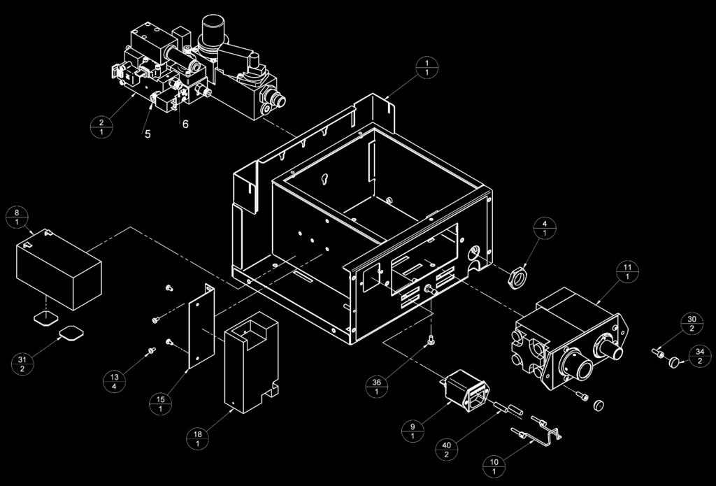
79 73

80 PARTS LIST 74

81 PARTS LIST Regulator Assembly and Control Block Assembly Item Part No. Description Quantity Regulator Assembly Control Block Assembly M3 X 35 Cap HD O Ring Ø8.1 X Ø
82 PARTS LIST Patient Block Assembly Item Part No. Description Quantity Diaphragm One-way valve Inline Relief Valve Check Valve Cap Taper Adaptor Tapered Conn Spring Guide Valve Body Seat Insert Drive Gas Block Valve Base O Ring M4 X 16 SKT HD Cap Screw Ss M4 Skiffy Cap M3 X 6 Grub Ss Cup M3 X 16 Cap HD Screw M4 X 8 Butt HD CHEM BLK M4 X 50 Cap Head SS O Ring RM Viton O Ring O Ring Ø27.6 X Compression Spring M4 Tappex Trisert M3 Tappex Trisert Mounting Plate Mounting Plate Label 1 76

83 PARTS LIST 77
84 9. APPENDIX APPENDIX 1 Care of Back-up Battery CAUTION Damage may occur if the battery is allowed to remain in a discharged state. Never discharge the battery to below 10.2 volts. A. Battery installed in ventilator The battery must be charged before the machine is released for use with an 14 hour charge from the ventilator s internal power supply (ventilator connected to the mains supply, but not running). Note that the mains power indicator on the front panel will show a yellow light during charging. Subsequently the recharge periods for a battery on a ventilator in store are similar to those in B, below. Batteries in machines in normal use will be kept charged by the internal power supply. Note that the Low Battery Alarm indicator may be displayed if automatic recharging is taking place as the ventilator is in use. B. Battery care/storage requirements. During storage, batteries will require a periodic recharge, the frequency of which is determined by the storage temperature, which must not exceed 50 o C (120 o F). Storage temperature Recharge period 38 to 50 o C (100 to 122 o F) 1 month 21 to 38 o C (70 to 100 o F) 3 months 7 to 21 o F (45 to 70 o F) 6 months 0 to 7 o C (32 to 45 o F) 9 months -5 to 0 o C (23 to 32 o F) 12 months Duration - recharge for a minimum of 12 hours (typically overnight). It is recommended that at each charge an updated label is affixed to the unit to indicate date of the last charge. C. Disposal of used batteries Follow all hospital, local, state and federal regulations. Note Removal/replacement of battery must only be undertaken by a trained technician 78
85 APPENDIX 2 APPENDIX 2 On-screen Menus NOTE: 1. All selection or changes in the menu are followed by a "CONFIRM" message prompt on the screen, and accompanied by a "BEEP" (user volume set) 2. The selected text or option will invert in colour 3. User settings menus only activate in Standby mode. 4. Clock menu, Upgrade menu, Diagnostic menu only activate in Standby mode. 5. Special Modes on-screen tab only activates in Spontaneous mode 6. Adult default settings VT=600 ml RATE=10 bpm IE RATIO=1:2 Plimit=38 cmh2o Ptarget=10 cmh2o 7. Paediatric default settings VT=150 ml RATE=15 BPM IE RATIO=1:2 Plimit=38 cmh2o Ptarget=10 cmh2o 79
86 Menu Structure O2 Monitor & Spirometry ESCAPE FROM MENU O2 MONITOR: on CALIBRATION: 100% HIGH ALARM SET: 105 LOW ALARM SET: 18 SPIROMETER: on SPIRO CALIBRATION: 0 L/min off / on (Toggle option 21 / 100% (Toggle option) (Integer) (Integer) off / on (Toggle option) 0 L/min / 10 L/min (Toggle option) Main Menu EXIT MENUS O2 MONITOR & SPIROMETRY FRESH GAS COMPENSATION: ON SPECIAL MODES WAVEFORM ALARM SETTINGS GAS MIXTURE: O2+AIR USER SETTINGS SERVICE MENU Fresh Gas Compensation ON / OFF Special Modes ESCAPE FROM MENU SUPPORT MODE: none TRIGGER: 5 L/min SIGH TO BREATH RATIO: 1:50 off/on Support Mode pick list none pressure simv smmv Sigh to Breath Ratio pick list 1:50 2:50 3:50 4:50 (Toggle option) Trigger pick list 0.7 L/min 0.7 L/min 0.7 L/min 0.5 L/min 1.0 L/min 1.5 L/min 2.0 L/min 2.5 L/min 3.0 L/min 4.0 L/min Waveform ESCAPE FROM MENU SECOND WAVEFORM: off Second waveform pick list off vol. vs time vol. vs press. Alarm settings ALARM MENU ESCAPE FROM MENU ALARM MODE : default HIGH TIDAL VOLUME: off VM MIN: 0.3 L VM MAX: 0.9 L VT MIN: 300 ml VT MAX: 900 ml APNOEA ALARM LIMIT: 0.3 cmh2o ALARM VOLUME: 50% default / user (Toggle option) off / on (Toggle option) (Integer) (Integer) (Integer) (Integer) (Integer) % (Integer) Gas mixture: O2+Air O2+AIR O2+N2O O2+Xe O2+He User Settings ESCAPE FROM MENU SELECT SETTINGS SAVE SETTINGS BACK LIGHT LEVEL: 50% VOLUME TYPE: tidal Service See next page Select settings ESCAPE FROM MENU USER1: CCT1 USER2: CCT2 USER3: CCT3 USER4: CCT4 USER5: CCT5 ADULT DEFAULT PAEDIATRIC DEFAULT Save settings ESCAPE FROM MENU USER1: CCT1 CONFIRM: CCT1 USER2: CCT2 CONFIRM: CCT2 USER3: CCT3 CONFIRM: CCT3 USER4: CCT4 CONFIRM: CCT4 USER5: CCT5 CONFIRM: CCT5 Backlight level 0-100% (integer) Volume type tidal/minute (toggle) 80
87 Service ESCAPE FROM MENU LANGUAGE: ENGLISH PRINT PATIENT DATA SERIAL MODE: none CLOCK MENU UPGRADE MENU AMBIENT PRESSURE: 988 mbar DISPLAY HISTORY *SERVICE PIN: 0 *ENGINEER MENU Language pick list ENGLISH ITALIANO TURKCE POLSKI ESPANOL Serial mode pick list NONE Philips SPACELABS Clock ESCAPE FROM MENU YEAR: 2005 MONTH: 3 DATE: 16 DOW: 3 HOUR: 9 MINUTE: 57 UPDATE CLOCK DAYLIGHT SAVING: off Clock pick list (integer) (integer) 1-12 (integer) 1-31 (integer) 1-7 (1 = Monday) (integer) 0-23 (integer) 0-59 (integer) off / on (toggle option) Upgrade ESCAPE FROM MENU I/O HARDWARE: 2 I/O FIRMWARE: v0.47 [Build 68] MAIN FIRMWARE: v0.92 [Build 32] REGISTRATION KEY: unknown UPGRADE FIRMWARE: unavailable ADD NEW FEATURE: unavailable History Display ESCAPE FROM MENU MANUFACTURER DATE : 03/03/05 TOTAL HOURS RUN: 100 LAST SERVICE DATE: 13/08/04 HOURS SINCE SERVICE : 100 DRIVE VALVE CYCLES: 1253 PATIENT VALVE CYCLES: 822 CUTOFF VALVE CYCLES: 72 *NOTE Service PIN Engineer Menu Sub-menus are not accessible by users. 81
88 APPENDIX 3 APPENDIX 3 AV-S Ventilator Spirometry System Ventilator Spirometry Measurement The AV-S ventilator drive gas and spirometry system uses a total of three mass flow gas sensors to monitor and then independently measure the gas flows within the ventilator and breathing system. This ensures that correct volumes are delivered to the patient. These monitors are measuring firstly in the ventilator delivery control system, and secondly in the patient breathing system. During use of the ventilator the user will set a required tidal volume and at the first breath the ventilator will use its precalibrated delivery flow rate valve settings to set the proportional delivery valve position to deliver the requested tidal volume. To confirm that the correct flow rate (tidal volume) is being delivered by the ventilator delivery system an internal flow sensor (a Honeywell AWM43300V mass flow sensor), monitors the delivered flow rate and makes adjustments every 30 ms using proportional regulation. As this sensor is always measuring the known drive gas rather than breathing system gas the volumes measured will always be independent of breathing system gas composition. This system ensures accurate delivery volume from the ventilator control unit. To monitor for correct delivery volumes in the breathing system there are two breathing system mass flow sensors (Honeywell AWM 720P1 spirometers). One sensor is located in the inspiratory limb, and one in the expiratory limb. Measurements are taken from these sensors to determine the actual delivered and exhaled gas volumes in the breathing system. This enable measurements to be made to compensate for fresh gas flow, compliance losses and possible breathing system leaks. During the inspiratory cycle the inspiratory flow sensor measures the gas volume delivered to the patient. The flow sensor output is read at least every 2 msec and then five sets of readings are averaged and the averaged value is sent every 10 ms to the processor for calculation of the volume delivered to the patient. This delivered volume will consist of the volume delivered from the ventilator bellows plus the fresh gas flow from the anaesthetic machine fresh gas supply, minus any compliance loss and minus any leak. This gives a total actual inspired tidal volume. A similar measurement method is used for the exhaled volume. During the exhalation period the measured exhaled volume is subtracted from the inspired volume, and at the end of exhalation. A negative (more gas coming out) volume indicates that fresh gas has increased the delivered volume. A positive volume (less gas coming out) indicates a leak in the circuit. The ventilator control system will then adjust the next delivered tidal volume, up to a maximum of 100 ml. This will bring the delivered volume to exactly as set. If the variation between set and delivered is greater than the maximum rate of change allowed, the adjustment will occur gradually over several breaths. The displayed volume is the average of the inspiratory and expiratory volumes. If this value is less or more than 50% of set volume, a low or high volume alarm is given. Breathing System Gas Composition Gas flow measurements are affected by the breathing system gas composition. To compensate for these effects the ventilator has a) a gas composition setting whereby the user is able to select the gasses being delivered, i.e. oxygen/air, oxygen/nitrous oxide etc, b) an oxygen monitor; Thus the ventilator knows the overall oxygen concentration and the majority of the remaining gas composition. 82
89 APPENDIX Altitude Effects Gas flow measurements are also affected by atmospheric pressure, in a linear relationship. To compensate for altitude effects an ambient pressure sensor is available. When the spirometers are calibrated for zero flow the ambient pressure is recorded so that the measured volume may be adjusted. The measured volume is multiplied by the ratio of Pamb to Pcal; where Pamb is the latest ambient pressure and Pcal is the ambient pressure recorded when the spirometers were calibrated at zero flow. Carrier Gas Effects The effect of air as the dilutent gas is different to that of nitrous oxide and as the ventilator includes only an oxygen monitor, the additional information of gas being ventilated is included to increase available accuracy. Anaesthetic Agent Effects The addition of anaesthetic agent is known also to increase the spirometry readings depending on the agent and its concentration by up to approximately 2%. Again this minor volume measurement variation is of no known clinical disadvantage and is therefore not compensated for other than that due to oxygen variation due to the percentage change. Water Vapour Effects Water vapour volumes in the breathing gas are not detectable in normal breathing system dynamics. Additional Features Additional spirometry features available for selection by the user are the ability to turn off the automatic compliance and fresh gas compensation and also the feedback provided by the oxygen monitor. In this event, the ventilator relies on the basic delivery look up table and the internal flow sensor to confirm delivery volumes as near as possible, under the circumstances. Accuracies for spirometry measurement are >300 ml ± 20% >100 ml <300 ml ± 20% <100 ml ± 50%. 83 Flow sensor description The microbridge mass airflow sensor operates on the theory of heat transfer. Mass airflow is directed across the surface of the sensing elements. Output voltage varies in proportion to the mass air or other gas flow through the inlet and outlet ports of the package. The specially designed housing precisely directs and controls the airflow across the microstructure sense element. The microbridge mass airflow sensor has a unique silicon chip based on advanced microstructure technology. It consists of a thin-film, thermally isolated bridge structure containing heater and temperature sensing elements. The bridge structure provides a sensitive and fast response to the flow of air or other gas over the chip. Dual sensing elements positioned on both sides of a central heating element indicate flow direction as well as flow rate. Laser trimmed thick film and thin film resistors provide consistent interchangeability from one device to the next. The microbridge mass airflow sensor uses temperature-sensitive resistors deposited within a thin film of silicon nitride. They are suspended in the form of two +bridges over an etched cavity in the silicon. The chip is located in a precisely dimensioned airflow channel to provide a repeatable flow response. Highly effective thermal isolation for the heater and sensing resistors is attained by etching the cavity space beneath the flow sensor bridges. The small size and thermal isolation of the microbridge mass airflow sensor are responsible for the extremely fast response and high sensitivity to flows. Dual Wheatstone bridges control airflow measurement - one provides closed loop heater control, the other contains the dual sensing elements.
 above ambient air temperature which is sensed by a heatsunk resistor on the chip.")
90 APPENDIX The heater circuit minimizes shift due to ambient temperature changes by providing an output proportional to mass flow. The circuit keeps the heater temperature at a constant differential (160 C) above ambient air temperature which is sensed by a heatsunk resistor on the chip. The ratiometric voltage output of the device corresponds to the differential voltage across the Wheatstone bridge circuit. Sensor flow characteristics The graph shown below is a typical flow versus resistance graph for the Honeywell spirometer head units for the flow range showing typical hysteresis between up and down flow measurements (and repeatability). Resistance (cmh2o) Flow (L/min) 84

91 APPENDIX 4 APPENDIX 4 Cleaning A Outside surfaces and bellows housing CAUTION Care must be taken not to allow liquids to run into the control unit; serious damage may result. Check that the unit is disconnected from the electrical supply before cleaning. Do not use cleaning solutions containing alcohol; the bellows housing may be damaged. To clean the outside surface of the ventilator, use a damp cloth. If necessary use a warm, mild detergent solution to remove resistant grime. Make sure that all detergent residues are fully removed after cleaning. Never use any harsh abrasive cleaning agent. The transparent acrylic bellows housing and, in general, the surfaces of the control unit are not scratch resistant. The inside of the bellows housing, under normal conditions, is not in contact with the breathing gas and therefore only needs cleaning as described above. Remove the bellows housing (A) by slightly twisting it counter-clockwise until the tabs at the bottom clear the bayonet locks, then lift it straight up from the base. Touchscreen Use a soft cloth only. Never use any harsh abrasive cleaning agent. Bellows and exhalation diaphragm valve Each time the bellows assemblies are opened for cleaning, all visible components must be carefully inspected and damaged parts must be replaced. Bellows As with all elastomers, the bellows material deteriorates with aging and should be inspected at least every six months or after 1200 hours of use, whichever comes first. The bellows must be replaced if it shows signs of aging. The bellows (B) can be removed by carefully pulling it off the base. If a paediatric bellows is fitted, the bellows adaptor (C) must also be removed. Do not dismantle the bellows. 85 B C F Paediatric Bellows Assembly
. Never use any hard object or abrasive agent to clean it; use only a soft cloth.")
92 APPENDIX 4 Exhalation Diaphragm Valve The exhalation diaphragm valve is under the bellows and can be removed by loosening the three thumbscrews. The valve seat is now visible. WARNING Great care must be taken. Do not damage the precision surface of the valve seat (D). Never use any hard object or abrasive agent to clean it; use only a soft cloth. If the valve seat is damaged, the diaphragm valve will leak and may cause serious malfunction. Clean the seat, and the metal disk (E) attached to the base of the diaphragm valve, thoroughly and remove all contamination from the surfaces of both components. E D Exhalation Diaphragm Valve Assembly NOTE If excessive contamination is discovered, check that a bacterial filter is used in the expiratory limb of the breathing circuit (or an HME at the patient tee-piece). After cleaning, check that the small O-ring (F) located in the bellows base under the diaphragm valve is in place. The ventilator will not function if the O-ring is missing. See next page for information on sterilisation procedures. Refitting Refit the diaphragm valve assembly to the bellows base and reassemble the bellows assembly If a paediatric bellows is fitted, press the adaptor (C) into the ventilator bellows assembly base, then fit the bellows. CAUTION Always check for correct fitment of the bellows (see illustration), and function test the ventilator before clinical use. Spirometer Sensors The sensors are built into the A200SP absorber, and cleaning and sterilisation can only be carried out when the absorber assembly is removed for cleaning. For further information please refer to the user instructions supplied with the A200SP. 86
93 APPENDIX 4 Sterilisation CAUTION To prevent possible damage to components, peak sterilisation temperatures must not exceed 134 o C (275 o F) for steam autoclave. Do not sterilise the ventilator control unit. Apart from the patient block assembly the internal components are not compatible with sterilisation techniques and may be damaged. Recommended Sterilisation Parameters Control Unit Patient Block Assembly 1. Clean, as described in section Autoclave at 134 o C, for a holding time of 3.5 minutes, using packaging and equipment as listed below: Packaging Pack the control unit with material which is permeable to air and steam but has an effective maximum pore size which is small enough to exclude microbial contamination. All wrapping materials must comply with EN 868: Packaging Materials for Sterilization of Wrapped Goods. Processing Equipment The sterilizer must comply with the stated performance class BS 3970 and HTM 2010 and with additional requirements stated in Section D. If a Porous-load sterilizer is used it must conform to the specifications in EN 285 and the safety specifications in EN 61010: Part Sterilization must be achieved by direct contact with good quality saturated steam. Post-processing Following reprocessing the patient block must be kept in a sterile plastic pouch to avoid being re-contaminated prior to being fitted to the ventilator. Refit in accordance with section Function test the ventilator before clinical use - see section Bellows Assembly Components Item Bellows Hoses O rings Bellows base Exhalation valve assembly Bellows canister Method Gas, liquid, autoclave (20 cycles maximum) Gas, liquid, autoclave Gas, liquid, autoclave Gas, liquid, autoclave Gas, liquid, pasteurise, low temperature autoclave Liquid, autoclave 87

94 APPENDIX 4 Oxygen Monitor Sensor Cleaning / Disinfection / Sterilisation In case of contamination the sensor (1) may be cleaned with distilled water and allowed to dry naturally. CAUTION The sensor is not suitable for sterilisation by steam or exposure to chemicals such as ethylene oxide or hydrogen peroxide. Do not immerse the sensor in any cleaning solution. Do not autoclave or expose the sensor to high temperatures. Bacterial Filter Use a breathing system bacterial filter in the expiratory limb of the breathing circuit to protect the oxygen sensor (see section 5.1.8). CAUTION Replacement/Disposal - always follow the instructions supplied with the filter, and always replace at the recommended interval. Oxygen Sensor Replacement WARNING The sensor contains: A) A small quantity of electrolyte, classified as a harmful irritant which is potentially hazardous. B) Lead Do not attempt to open a cell. ALWAYS check the integrity of the sensor assembly before use. Once exhausted, the sensor must be disposed of according to hospital, local, state and federal regulations. Remove and Refit Replacement parts: Sensor 1. Detach the cable connector (2) from the sensor (1). 2. Unscrew the sensor from the A200SP Absorber, and discard. 3. Discard the expired sensor. 4. Screw the new sensor (1) into the absorber. 5. Attach the cable connector (2). 6. Fit the assembly into the absorber. 7. Calibrate the new sensor see Appendix 6. (check software version) 8. Dispose of the used components according to hospital, local, state and federal regulations
 connected into the ventilator USB port (2). IMPORTANT NOTES: 1. The ventilator must be connected only to a USB floppy disk drive, as illustrated.")
95 APPENDIX 5 APPENDIX 5 Software Upgrade Installation Procedure Automatic Software Upgrade Installation 2 The AV-S software is designed to be automatically upgraded when connected to an auto-upgrade disc with a USB floppy drive (1) connected into the ventilator USB port (2). IMPORTANT NOTES: 1. The ventilator must be connected only to a USB floppy disk drive, as illustrated. Use an industry-standard drive for this application, to avoid data transfer errors 2. It is not necessary to remove the cover from the ventilator for the software to be upgraded automatically. 3. Do not install the upgrade from a PC, or USB Memory Stick device 1 Automatic Software Upgrade. 1. Connect the AV-S to a mains power source, but do not power the ventilator on. 2. Connect a floppy disk drive to the USB port on the rear of the ventilator. Ensure the upgrade installation disk is inserted in the drive. 3. Switch the AV-S on. After a self-testing sequence, the floppy disk drive should power up and display on screen the upgrade status, followed by the success or failure of upgrade. 4. When instructed, switch off the ventilator by pressing and holding the on/off button for about six seconds. 5. Disconnect the the floppy disk drive cable from the ventilator USB connector (2) and switch the ventilator on. 6. Check on the AV-S start-up screen that the software version matches the installation disk. 7. Carry out the valve calibration procedure detailed in section Read the notes on the datasheet issued with the upgrade. 9. Ensure that any User Datasheet that accompanies the upgrade is read and understood by the clinicians that will use the ventilator. 89


96 APPENDIX 6 Calibration and Output Checks for a New Ventilator Applicable to Software version: v On-Screen Menus To Access: Press the menu switch on the front panel EXIT MENUS O2 MONITOR & SPIROMETRY FRESH GAS COMPENSATION: ON SPECIAL MODES WAVEFORM ALARM SETTINGS GAS MIXTURE: O2+AIR USER SETTINGS SERVICE MENU To Exit: Press the menu switch on the front panel, or, select EXIT MENUS and press the navigator wheel. Menu Switch Navigator Wheel and Press Button Turn the wheel to scroll through the menus. Press the wheel to enter the required sub-menu. Rotate the wheel to change the value of displayed parameters. Press the wheel to confirm the required value. Before clinical use for the first time, the following Valve Calibration, Spirometry Calibration, and Volume Delivery Checks must be carried out: Drive Valve and Patient Valve Calibration 1. Disconnect the hoses from the Driving Gas Output (A), Patient Pressure Connector (B) and Exhaust outlet (C) on the rear of the ventilator. Calibrate the pressure transducers: Press the menu switch Scroll down, select SERVICE MENU Scroll down, select SERVICE PIN Enter PIN: 123 Select ENGINEER MENU Select PENLON OPTIONS MENU Select CAL PRESSURE This will zero all pressure transducers. Check that the Barometric Pressure reading is correct, if necessary adjust, and confirm. 2. Disconnect the fresh gas hose from the Common Gas Outlet. Switch the Bag/Vent switch (D) to Bag and remove the bag from the arm (E). Remove the patient circuit. D C E B A Main menu EXIT MENUS O2 MONITOR & SPIROMETRY FRESH GAS COMPENSATION: ON SPECIAL MODES WAVEFORM ALARM SETTINGS GAS MIXTURE: O2+AIR USER SETTINGS SERVICE MENU Service menu ESCAPE FROM MENU LANGUAGE: ENGLISH PRINT PATIENT DATA SERIAL MODE: none CLOCK MENU UPGRADE MENU AMBIENT PRESSURE: 988 mbar DISPLAY HISTORY SERVICE PIN: 0 ENGINEER MENU 90

97 APPENDIX 6 Calibrate the drive gas flow transducer: Select O2 MONITOR& SPIROMETRY Select CAL. SPIRO If menu shows calibration at 10 L/min, rotate the wheel to set at 0 L/min Press to confirm, note that display will flash a message This will zero the Drive Flow Transducer. O2 Monitor & Spirometry menu ESCAPE FROM MENU O2 MONITOR: on CALIBRATION: 100% HIGH ALARM SET: 105 LOW ALARM SET: 18 SPIROMETER: on > SPIRO CALIBRATION: 0 L/min 3. Use a safety bung to occlude the Driving Gas Output (A). Select ENGINEER MENU Select CAL VALVE MENU Select VALVE CAL TYPE Select: zero dv Wait for display message: zero dv cal complete 4. Remove the bung. Reconnect hoses to Driving Gas Output (A) and Patient Pressure Connector (B). Reconnect the fresh gas hose to the Common Gas Outlet. Connect the breathing circuit and test lung. Select Vent on absorber Bag/Vent switch. Set a fresh gas flow of 5 L/min. Wait for the bellows to fully inflate. Select ENGINEER MENU Select CAL VALVE MENU Select VALVE CAL TYPE Select: zero pv Wait for display message: Patient valve calibrated Reduce gas flow to minimum. 5. Disconnect the drive gas hose from the rear of the absorber (F). Connect a flow measurement device. Select ENGINEER MENU Select CAL VALVE MENU B A Select VALVE CAL TYPE Select: dv meas Check measured value is approximately 20 L/min. If not, adjust using Trim Valve Flow on Menu. After each trim valve flow adjustment press the navigator wheel to confirm change. Wait for the displayed value to adjust and settle to 20 L/min. Select none from Menu to end calibration. Remove the flow measurement device, but leave the hose disconnected. F 91

98 APPENDIX 6 6. Select ENGINEER MENU Select CAL VALVE MENU Select VALVE CAL TYPE Select: dv curve Observe valve oscillation and increasing flow delivery up to maximum flow. 7. Valve calibration is now complete. Spirometer Calibration 1. Check the condition of the external Spirometer cables and connections. 2. Disconnect the fresh gas hose from the anaesthesia machine Common Gas Outlet. Switch the Bag/Vent (D) switch to 'Bag'. Remove the bag from bag arm (E). Remove the test lung from the patient connector if fitted (or remove patient circuit). Ensure the gas scavenging circuit is not connected. 3. Check Spirometer is enabled in menu. 4. From main menu select O2 MONITOR & SPIROMETRY. Select SPIRO CALIBRATION 5. Rotate the navigator wheel until '0 L/min' is displayed. Press Navigator wheel to confirm setting. This will calibrate the spirometry system. The display will flash 'Calibrating Zero'. 6. If successful, 'Calibration complete' will be displayed. 7. Connect a short hose between the CGO and the absorber Expiratory connection (G). Connect the absorber Fresh Gas connector to the Bag arm connector (H) to ensure a closed system. 8. Connect a short hose from the Inspiratory connector (J) open to atmosphere. This will reduce vale oscillation. Adjust oxygen flowmeter on anaesthetic machine to achieve an accurate 10 L/min flow G J D O2 Monitor & Spirometry menu ESCAPE FROM MENU O2 MONITOR: on CALIBRATION: 100% HIGH ALARM SET: 105 LOW ALARM SET: 18 SPIROMETER: on > SPIRO CALIBRATION: 0 L/min H E 9. Re-enter O2 MONITOR & SPIROMETRY Select SPIRO CALIBRATION. 92
99 APPENDIX Rotate Navigator wheel until 'Calibrate 10 L/min' is displayed. Press Navigator wheel to confirm. Display will flash 'Calibrating 10 litres' 11. If successful, 'Calibration complete' will be displayed. 12. Reconnect fresh gas hose, patient circuit and manual bag. Reset the Bag/Vent switch to 'Vent' position. Volume Cycle and Flow Compensation Tests 1. Switch Ventilator to 'Volume ' Mode 2. Set 'Vt' to 600 ml, 'BPM' to 10, 'I:E' to 1:2, and 'Pressure Limit' to 80. Set the flow on the anaesthetic machine to basal flow. 3. From the main menu select FRESH GAS COMPENSATION: OFF. The bellows delivers 600 ml + 50 ml, but the measured volume may be reduced to as low as 500 ml with a standard test lung, due to the compliance losses of the circuit. 4. Note: If bellows delivery is out of specification repeat the Valve Calibration procedure. Main menu EXIT MENUS O2 MONITOR & SPIROMETRY FRESH GAS COMPENSATION: ON SPECIAL MODES WAVEFORM ALARM SETTINGS GAS MIXTURE: O2+AIR USER SETTINGS SERVICE MENU 5. Apply a flow of 8 L/min Oxygen from the Anaesthetic Machine. Check that the displayed 'Vt Meas' value rises. 6. From menu select FRESH GAS COMPENSATION: ON. Allow 2 minutes for the reading to stabilise. Observe that the bellows delivers less gas than before. Check displayed 'Vt Meas.' = 600 ml +/- 50 ml. Using a Wrights Respirometer, check the expiratory volume value is within + 50 ml of the displayed value. 7. Note: If Vt Meas is out of specification, repeat zero spirometry calibration, and 10 l/min spirometry calibration (it may be necessary to set a flow slightly above or below the 10 l/min graduation on the flowmeter, due to tolerance mismatch between the flow sensor and the flow tube). 93
100 APPENDIX 6 Main Menu Amendments : v /.02 /.04 On-screen Menu Structure Additional sub-menu: Leak Test Main Menu EXIT MENUS O2 MONITOR & SPIROMETRY LEAK TEST MENU FRESH GAS COMPENSATION: ON SPECIAL MODES WAVEFORM ALARM SETTINGS GAS MIXTURE: O2+AIR USER SETTINGS SERVICE MENU Leak Test ESCAPE FROM MENU <START/STOP LEAK TEST> LEAK STATUS: unknown LEAK LEVEL: 0 ml/min BSYS COMP 7.0 ml/cmh2o 94
101

102 Cat No Doc No AV-S 0208 SM June 2008 Manufactured by: Penlon Limited Abingdon Science Park Barton Lane Abingdon OX14 3PH UK Technical Support Tel: 44 (0) Fax: 44 (0) International Sales Tel: Fax: UK Sales Tel: Fax:
AV-S Ventilator User Manual
 AV-S Ventilator User Manual Partnership for Life IMPORTANT Servicing and Repairs In order to ensure the full operational life of this ventilator, servicing by an engineer trained by the manufacturer should
Draft Copy July AV-S Ventilator. Partnership for Life. Service Manual. Remote Display Module and Interface for use with A200SP Absorber
 Draft Copy July 2005 No update will be given AV-S Ventilator Remote Display Module and Interface for use with A200SP Absorber Service Manual Partnership for Life THE IMPORTANCE OF PATIENT MONITORING WARNING
AV-S Ventilator User Manual. This manual contains information for software upgrade v
 AV-S Ventilator User Manual This manual contains information for software upgrade v.1.87.01 USER DATASHEET AV-S Ventilator User Manual Software Version 1.87.01 Addendum to the User Manual Introduction
Anesthesia Solutions. Prima SP and Prima SP2 Anesthesia Systems. The Future of Anesthesia. Partnership for Life
 Anesthesia Solutions The Future of Anesthesia Prima SP and Prima SP2 Anesthesia Systems The Penlon Anesthesia System Range provides the user with their choice of advanced, easy to use anesthesia systems
AUTOVENT 4000 VENTILATOR
 OVERVIEW AUTOVENT 4000 Only properly trained and approved Escambia County Bureau of Public Safety Paramedics are to use the AutoVent 4000 ventilator manufactured by LSP to transport patients already on
SLE4000. Infant Ventilator with touch-screen operation. When the smallest thing matters
 SLE4000 Infant Ventilator with touch-screen operation When the smallest thing matters SLE4000 - The Total Solution for Conventional Infant Ventilation SLE is a world leader in the design and manufacture
SATURN EVO COLOR A N A E S T H E S I A S Y S T E M. Manufacturer of high quality anaesthesia products
 Saturn Evo SATURN EVO COLOR A N A E S T H E S I A S Y S T E M i n t e l l i g e n t s i m p l i c i t y Manufacturer of high quality anaesthesia products SATURN EVO COLOR PATIENT SAFETY AND USER PATIENT
SLE5000 Neonatal Ventilator with High Frequency Oscillation
 SLE5000 Neonatal Ventilator with High Frequency Oscillation The SLE5000 is superb: the best High Frequency Ventilator I ve used When the smallest thing matters SLE5000 - The Total Solution for Infant Ventilation
HONG KONG COLLEGE OF ANAESTHESIOLOGISTS TECHNICAL GUIDINES RECOMMENDATIONS ON CHECKING ANAESTHESIA DELIVERY SYSTEMS
 RECOMMENDATIONS ON CHECKING ANAESTHESIA DELIVERY SYSTEMS 1. INTRODUCTION An anaesthesia delivery system includes any machine, equipment or apparatus which supplies gases, vapours, local anaesthesia and/or
Aespire 7100 Essential performance Compact design
 GE Healthcare Aespire 7100 Essential performance Compact design Features Enhanced monitor integration capabilities with our Datex-Ohmeda Anesthesia Monitor and Compact Anesthesia monitor Lightweight and
SLE5000 Infant Ventilator with HFO
 SLE5000 Infant Ventilator with HFO When the smallest thing matters SLE5000 - The Total Solution for Infant Ventilation Shown on optional roll stand. Ventilator may be mounted either way round on stand.
IMPACT. Uni-Vent. Eagle. Model 754 Portable Ventilator
 IMPACT Uni-Vent Eagle Model 754 Portable Ventilator Uni-Vent Eagle Model 754 Portable Ventilator OPERATOR TRAINING PROGRAM FOR: Critical Care Transport Aero medicine Emergency Services Uni-Vent Eagle Model
Operation of Oxylog 3000 ventilator
 Operation of Oxylog 3000 ventilator Overview Suitable for patients from approximately 7Kg body weight upwards (smallest tidal volume 50mls). Entirely power dependant- will not ventilate if no available
Operation and Maintenance of the EPV200 Portable Ventilator
 Operation and Maintenance of the EPV200 Portable Ventilator 1 Applications of the EPV200 The EPV200 Portable Ventilator is a gas powered electronically controlled mechanical ventilator, designed to provide
Technical Data and Specifications
 Technical Data and Specifications INTENDED USE Ventilator designed to provide Invasive and Non-invasive ventilation for the critical care management of adult, pediatric and neonate-infant (including premature)
Prima SP2/3 Anaesthetic Machine Range Service Manual Partnership for Life
 Sign-off Copy Prima SP2 USA August 2005 Prima SP2/3 Anaesthetic Machine Range Service Manual Partnership for Life IMPORTANT Servicing and Repairs In order to ensure the full operational life of this anaesthetic
Recommendations on Checking Anaesthesia Delivery Systems
 Page 1 of 11 Recommendations on Checking Anaesthesia Delivery Version Effective Date 1 Oct 1992 (reviewed Feb 07, Feb 02) 2 2004 3 Nov 2011 4 Dec 2016 Document No. HKCA T1 v4 Prepared by College Guidelines
S/5 Aespire. Quick Reference Guide
 S/5 Aespire Quick Reference Guide Anesthesia system controls 1 Turn on the system 2 7100 controls and monitored data 3 Menu map 4 Set the ventilation mode 5 Set ventilator controls 6 Vaporizer controls
A9600 Anesthesia Workstation. Your healthcare, we care.
 A9600 Anesthesia Workstation Your healthcare, we care. A9600 is an advanced yet easy to use anesthesia workstation that provides accurate, pneumatically driven and electronically controlled ventilation.
Panther 5 Acute Care Ventilator
 1 HIGHLIGHTS High performance and advanced features target the ICU environment Utilizes an internal blower with a specially designed flow control valve removing the need for using compressed air without
Hallowell EMC Anesthesia WorkStation Operating Manual
 Hallowell EMC Anesthesia WorkStation Operating Manual PN 000a2770 Anesthesia WorkStation A compact (9" W x 9" D x 15" H), convenient system for use on animals under 7 kg (15 lb.) Hallowell Engineering
Anesthesia Workstation
 Your healthcare, we care. A9800 Anesthesia Workstation Technical Parameters A9800 Ventilation Modes Alarms Volume Control Pressure Control SIMV with Pressure Support (SIMV + PS) - with Volume or Pressure-type
2015 Hamilton Medical AG. All rights reserved. Printed in Switzerland.
 HAMILTON-T1 Quick Guide This Quick Guide is intended as a useful reference for ventilation of adult and pediatric patients. It does not replace the clinical judgment of a physician or the content of the
The centerpiece of a comprehensive anaesthesia workstation
 The centerpiece of a comprehensive anaesthesia workstation IntelliSave AX700 anaesthesia machine A slim design with rich functionality The IntelliSave AX700 is a comprehensive anaesthesia machine from
Narkomed MRI-2. A perfect fit for the MRI environment. Because you care. Emergency Care Perioperative Care Critical Care Perinatal Care Home Care
 Narkomed MRI-2 A perfect fit for the MRI environment Emergency Care Perioperative Care Critical Care Perinatal Care Home Care Because you care The complete anesthesia solution for the MRI environment A
Prima SP Anaesthetic Machine Range Service Manual
 Prima SP Anaesthetic Machine Range Service Manual Quality and Assurance in Anaesthesia THE IMPORTANCE OF PATIENT MONITORING WARNING Anaesthetic systems have the capability to deliver mixtures of gases
AUGUST ANESTHESIA MACHINES MEDICAL PRODUCTS ANESTHESIA MACHINES. Quality System Standard applied: ISO 9001, ISO 13485
 ANESTHESIA MACHINES AUGUST - 2008 MEDICAL PRODUCTS ANESTHESIA MACHINES Quality System Standard applied: ISO 9001, ISO 13485 CE Certification 93/42/EEC. Arsiconsult 38, Av. Guy de Maupassant 78400 Chatou
Pressure Automated Calibration Equipment
 GE Measurement & control Pressure Automated Calibration Equipment Safety Instructions and User Guide - K0447 PACE5000 PACE6000 K0447 Issue No. 9 1 10 1 PACE5000 1 2 3 4 5 PACE6000 2 6 7 8 3 4 5 6 7 8 9
Siesta i Whispa Integrated technology
 Siesta i Whispa Integrated technology Functional, fail-safe and flexible to your needs Take a good look, and you ll be surprised by the many forward-thinking features of the Siesta i Whispa anaesthesia
A200SP Circle Absorber Service Manual
 A200SP Circle Absorber Service Manual IMPORTANT Includes component upgrade information : a) Inspiratory/expiratory valves b) Canister and Release/Lock System; c)apl Valve Partnership for Life IMPORTANT
Ventilator Training Module
 Ventilator Training Module LTV (Lap Top Ventilator) Teaching Script LTV User guides: http://www.carefusion.com/documents/guides/user-guides/rc_ltv-1000_ug_en.pdf http://www.carefusion.com/documents/guides/user-guides/rc_ltv-1100_ug_en.pdf
e700 Automatic Transport Ventilator User Manual e700 User Manual (15PL Rev.14 28_8_2017)
") e700 Automatic Transport Ventilator User Manual Table of Contents Chapter 1 Safety... 1 Chapter 2 Intended Use.. 4 Chapter 3 Overview.... 5 3.1 Control and Display Layout...... 5 3.2 Function Keys......
e700 Automatic Transport Ventilator User Manual Table of Contents Chapter 1 Safety... 1 Chapter 2 Intended Use.. 4 Chapter 3 Overview.... 5 3.1 Control and Display Layout...... 5 3.2 Function Keys......
Dameca MRI 508. State-of-the-art MRI technology
 Dameca MRI 508 State-of-the-art MRI technology The closer, the safer the better Hospitals have long awaited an anaesthesia machine that can be used close to their MRI scanner. The Dameca MRI 508 is it
Your patients, our primary focus
 Your patients, our primary focus Siesta i Whispa anesthesia machine Functional, fail-safe and flexible to your needs Take a good look, and you ll be surprised by the many forward-thinking features of the
AUTOMATIC GAS MANIFOLDS
 AUTOMATIC GAS MANIFOLDS Phoenix Pipeline Products Limited. Unit 8, McKenzie Industrial Park, Tel No.: 44 (0) 161 428 7200 Bird Hall Lane, Fax No.: 44 (0) 161 428 7010 Stockport, Email: info@p3-phoenix.com
ASSISTANCE. Cardinal Health Pulmonetic Systems Medina Rd., Suite 100 Minneapolis, Minnesota
 ASSISTANCE Cardinal Health Pulmonetic Systems 17400 Medina Rd., Suite 100 Minneapolis, Minnesota 55447-1341 Customer Care: (800) 754-1914 (763) 398-8500 Fax: (763) 398-8403 Website: www.cardinalhealth.com/viasys
INTENSIVE CARE VENTILATORS
 INTENSIVE CARE VENTILATORS iternis ADV INTENSIVE CARE VENTILATION FOR ALL PATIENT CATEGORIES Design Features HEYER iternis ADV s 12-inch touch-screen display combines comprehensive, easy-to-follow user
AIR/OXYGEN BLENDER INSTRUCTION MANUAL
 BIO-MED DEVICES AIR/OXYGEN BLENDER INSTRUCTION MANUAL CATALOG #2120 REV 042203 BIO-MED DEVICES INC. 1445 BOSTON POST ROAD, GUILFORD, CT 06437 (203) 458-0202 FAX (203) 458-0440 www.biomeddevices.com TABLE
RAM 4021 Operation Manual
 RAM 4021 Operation Manual Worldwide Manufacturer of Gas Detection Solutions TABLE OF CONTENTS RAM 4021 For your safety...3 Description...3 Set-up mode...4 Annunciator lights/alarms...4 Operation...5 Calibration...6
The anaesthesia workstation focused on you
 by The anaesthesia workstation focused on you With the most advanced anaesthesia Accuracy and performance Equipped with the most advanced ventilation modes. Electronic rotameters with precise mass-flow
An intuitive and innovative answer to your anaesthesia challenges
 An intuitive and innovative answer to your anaesthesia challenges Dameca AX500 anaesthesia machine Meeting your needs today and tomorrow As an expert in anaesthesia care, you are looking to continuously
e600 Automatic Transport Ventilator User Manual e600 User Manual (15PL Rev.7 28_8_2017)
") e600 Automatic Transport Ventilator User Manual Table of Contents Chapter 1 Safety. 1 Chapter 2 Intended Use.. 4 Chapter 3 Overview. 5 3.1 Control and Display Layout........ 5 3.2 Function Keys......
e600 Automatic Transport Ventilator User Manual Table of Contents Chapter 1 Safety. 1 Chapter 2 Intended Use.. 4 Chapter 3 Overview. 5 3.1 Control and Display Layout........ 5 3.2 Function Keys......
RAM Operation Manual. Worldwide Manufacturer of Gas Detection Solutions
 RAM 4021 Operation Manual Worldwide Manufacturer of Gas Detection Solutions TABLE OF CONTENTS RAM 4021 For Your Safety... 2 Description.... 2 Setup Mode.... 2 Lights/Alarms.... 3 Operation.... 4 Calibration....
Safe Accurate Reliable. CWM-301 Anesthesia System
 Safe Accurate Reliable CWM-301 Anesthesia System CWM-301 Anesthesia System Extraordinary performance points 8.4 inch colour LCD screen Compact Anesthesia ventilation system with the standard of ISO 9001:13485
RAM 4021-PR. Operation Manual. Worldwide Manufacturer of Gas Detection Solutions
 RAM 4021-PR Operation Manual Worldwide Manufacturer of Gas Detection Solutions TABLE OF CONTENTS RAM 4021-PR For Your Safety... 2 Description.... 2 Setup Mode.... 2 Lights/Alarms.... 3 Operation.... 4
RAM Operation Manual
 RAM 4021-1 Operation Manual Worldwide Manufacturer of Gas Detection Solutions TABLE OF CONTENTS RAM 4021-1 For Your Safety... 2 Description... 2 Setup Mode... 3 Lights/Alarms... 3 Operation... 4 Calibration...
Table of Contents. Operating Instructions. Resource v.2 Conserving Regulator
 Operating Instructions Table of Contents Resource v.2 Conserving Regulator Safety Information Device Precautions Introduction Product Features Product Specifications Feature Illustrations Set Up Usage
Astral in AirView: Improving patient care through connectivity. ResMed.com
 Astral in AirView: Improving patient care through connectivity ResMed.com This guide will assist you with: Setting up the ResMed Connectivity Module for Astral 2 Troubleshooting the ResMed Connectivity
Operating Instructions Part No
 DIGITAL AUTOMATIC TYRE INFLATOR Operating Instructions Part No. 11.0578 Thank you for selecting this Jamec Pem Automatic Tyre Inflator. Please read this manual before carrying out any installation or service
Fabius Tiro TM. Designed for your environment. Emergency Care Perioperative Care Critical Care Perinatal Care Home Care
 Fabius Tiro TM Designed for your environment Emergency Care Perioperative Care Critical Care Perinatal Care Home Care Traditional hospital ORs have their needs... With more surgical procedures being performed
FLIGHT MEDICAL INNOVATIONS LTD. FLIGHT 60 Ventilator. Operator's Manual
 FLIGHT MEDICAL INNOVATIONS LTD. FLIGHT 60 Ventilator Operator's Manual LIT-0014 Rev. A10 OPERATING MANUAL-FLIGHT60 SYMBOL KEYPAD WITH OPTIONAL INTERNAL O2 MIXER Legal Notice Legal Notice Disclaimer FLIGHT
Pressure Regulator. Instructions for Use
 Pressure Regulator Instructions for Use 702-0083.9 December 2017 1. Symbols Warning! Caution! Indicates a potentially hazardous situation which, if not avoided, could result in injury to the patient, the
RAM Operation Manual. Worldwide Manufacturer of Gas Detection Solutions
 RAM 4021 Operation Manual Worldwide Manufacturer of Gas Detection Solutions TABLE OF CONTENTS RAM 4021 For Your Safety... 2 Description.... 2 Setup Mode.... 2 Lights/Alarms.... 3 Operation.... 4 Calibration....
Oxylog 3000 plus Emergency & Transport Ventilation
 Oxylog 3000 plus Emergency & Transport Ventilation Offering high ventilation performance with features such as AutoFlow, integrated capnography and non-invasive Ventilation, the compact and robust Oxylog
TR Electronic Pressure Regulator. User s Manual
 TR Electronic Pressure Regulator Page 2 of 13 Table of Contents Warnings, Cautions & Notices... 3 Factory Default Setting... 4 Quick Start Procedure... 5 Configuration Tab... 8 Setup Tab... 9 Internal
State-of-the-art anesthesia technology
 State-of-the-art anesthesia technology anesthesia system Get closer to the MRI scanner Superb certified performance in close proximity to strong magnetic fields. Our innovative machine provides benefits
Airox Supportair Ventilator
 Airox Supportair Ventilator A versatile hospital ventilator with a titration platform that enables a smooth transition to the patient s home care ventilator Titration Platform The Supportair ventilator
Operation and Maintenance of the MCV100 and MCV100-B Portable Ventilator
 Operation and Maintenance of the MCV100 and MCV100-B Portable Ventilator 1 Applications of the MCV100(B) The MCV100 and MCV100-B Mass Casualty Ventilators are electronically controlled portable ventilators,
Astral in AirView: Improving patient care through connectivity. ResMed.com
 Astral in AirView: Improving patient care through connectivity ResMed.com Using Astral in AirView via the ResMed Connectivity Module (RCM) Astral is ResMed s portable, invasive and non-invasive life support
Blease900 Ventilator PATIENT CENTERED VENTILATION
 Blease900 Ventilator PATIENT CENTERED VENTILATIN PATIENT CENTERED VENTILATIN From the first Blease/Manley ventilator sixty years ago, Spacelabs Healthcare has built a heritage of innovative and intuitive
PERFORMANCE EVALUATION #34 NAME: 7200 Ventilator Set Up DATE: INSTRUCTOR:
 PERFORMANCE EVALUATION #34 NAME: 7200 Ventilator Set Up DATE: 1. **Identify and name the filters on the 7200ae. 2. **Explain how each filter is sterilized. 3. **Trace the gas flow through the ventilator
Your patients, our primary focus. Siesta i Whispa anesthesia machine
 Your patients, our primary focus Siesta i Whispa anesthesia machine Functional, and flexible At Dameca we are not just committed to meeting the healthcare needs of today. We also think about tomorrow.
Aestiva/5. Operation Manual - Part 1. Software Revision 4.X System Controls, Operation, Checkout
 Aestiva/5 Operation Manual - Part 1 Software Revision 4.X System Controls, Operation, Checkout User Responsibility This Product will perform in conformity with the description thereof contained in this
2 PRE USE FUNCTION CHECK 3 OPERATING PROCEDURE 4 SERVICING. 5 CAREvent ALS ACCESSORIES 11
 THE RESUSCITATOR MUST BE THOROUGHLY CLEANED AFTER EACH PATIENT USE. 1. Operate CAREvent ALS Handheld Resuscitator to blow out any contaminant from the patient valve. 2. Ensure CAREvent ALS Handheld Resuscitator
GE Healthcare. Centiva/5 Critical Care Ventilator. Meet a new level of expectations
 GE Healthcare Centiva/5 Critical Care Ventilator Meet a new level of expectations Intergrating performance and value Marry form and function In an environment where time and space are tight, the design
RAM 4021-DPX Operation Manual
 RAM 4021-DPX Operation Manual Worldwide Manufacturer of Gas Detection Solutions TABLE OF CONTENTS ABL 4021-DPX / RAM 4021-DPX For Your Safety... 3 Description... 3 Setup Mode... 4 Lights/Alarms... 4 Operation...
FLIGHT 60 Ventilator T-edition
 FLIGHT MEDICAL INNOVATIONS LTD. FLIGHT 60 Ventilator T-edition Operator's Manual LIT-0106 Rev. A00 OPERATING MANUAL-FLIGHT60 TURBINE for USA Legal Notice Legal Notice Disclaimer FLIGHT MEDICAL INNOVATIONS
The SAV04 Small Animal Ventilator. Contents Page
 The SAV04 Small Animal Ventilator Contents Page SAV04 Ventilator Parts and Controls... 2 General... 4 Basis of operation... 4 Points to note... 5 Using the SAV04 for the first time... 5 The unit controls...
Ventilators. Dr Simon Walton Consultant Anaesthetist Eastbourne DGH KSS Basic Science Course
 Ventilators Dr Simon Walton Consultant Anaesthetist Eastbourne DGH KSS Basic Science Course Objectives Discuss Classification/ terminology Look at Modes of ventilation How some specific ventilators work
The anaesthesia workstation focused on you
 by The anaesthesia workstation focused on you The anaesthesia Accuracy and performance Equipped with the most advanced ventilation modes. Electronic rotameters with precise mass-flow sensors, allowing
MP15 Jockey Pump Controller
 Setup and Operating Instructions MP15 Jockey Pump Controller This manual provides general information, installation, operation, maintenance, and system setup information for Metron Model MP15 Jockey Pump
CPR MEDICAL DEVICES INC. OPERATING MANUAL FOR RESUSCITATOR
 CPR MEDICAL DEVICES INC. OPERATING MANUAL FOR OXYLATOR FR-300 RESUSCITATOR Symbols used in the Operating Manual for the Oxylator FR-300 and/or on the Oxylator FR-300 unit: WARNING! Do not use grease or
A200SP Circle Absorber Service Manual
 A200SP Circle Absorber Service Manual Partnership for Life IMPORTANT Servicing and Repairs In order to ensure the full operational life of this device, servicing by a Penlon-trained engineer should be
THE GE AISYS ANAESTHETIC MACHINE
 THE GE AISYS ANAESTHETIC MACHINE All essential components of the anaesthetic machine are shown in the diagram below. Each major component will be explained in detail. The Gas Inlet Module In the diagram
DRAFT U S E R M A N U A L CAUTION. Model: 19MFA1001 Series. Federal (USA) law restricts this device to sale by or on the order of a physician.
 law restricts this device to sale by or on the order of a physician.") U S E R M A N U A L Model: 19MFA1001 Series SAVE THESE INSTRUCTIONS Federal (USA) law restricts this device to sale by or on the order of a physician. 300 Held Drive Tel: (+001) 610-262-6090 Northampton,
U S E R M A N U A L Model: 19MFA1001 Series SAVE THESE INSTRUCTIONS Federal (USA) law restricts this device to sale by or on the order of a physician. 300 Held Drive Tel: (+001) 610-262-6090 Northampton,
AIR COMPRESSOR OPERATING INSTRUCTION AND PARTS LIST
 AIR COMPRESSOR OPERATING INSTRUCTION AND PARTS LIST OIL-LESS TYPE IMPORTANT: PLEASE READ CAREFULLY BEFORE STARTING OPERATIONS. THE CONTENTS ARE FOR GENERAL INFORMATION OF ALL THE SIMILAR MODELS. Record
Blendox AII5000F Inhalation Antalgic System. User s Manual :SP-Y Series No. Version :A1. Date of Review:
 AII5000F Inhalation Antalgic System User s Manual Series No. :SP-Y53564 Version :A1 Date of Review:2012-04-29 To Users: Welcome to Blendox AII5000F Inhalation Antalgic System (hereafter referred to as
The Merlin Small Animal Ventilator by Vetronic Services Ltd. Contents page. Introduction.2. Features of Merlin. 3
 The Merlin Small Animal Ventilator by Vetronic Services Ltd Contents page Introduction.2 Features of Merlin. 3 A brief over-view of how Merlin works 4 Merlin Front Panel and Controls. 6 Gas Port Connections..
Tafonius. Auxiliary Mode Operating Manual A USERS GUIDE
 Tafonius Auxiliary Mode Operating Manual A USERS GUIDE v09feb2011 Notes: Printed: 28/Feb/11 Page 2 of 15 DOCA4956 Table of Contents Running Tafonius with the Auxiliary Control System...5 Turning Tafonius
O-Two Self-Study Guide. Equinox Relieve
 O-Two Self-Study Guide Equinox Relieve PRODUCT DESCRIPTION/PRINCIPLES OF OPERATION The Equinox Relieve provides spontaneously breathing patients with a preset mixture of oxygen and nitrous oxide for analgesia
Pressure Regulators. Instructions for Use
 Pressure Regulators Instructions for Use 702-0032.11 May 2014 1. Symbols Warning! Caution! Indicates a potentially hazardous situation which, if not avoided, could result in personal injury to the user
Flow meter. bellow vaporizer. APL valve. Scavenging system
 Introductory Lecture Series: The Anesthesia Machine PORNSIRI WANNADILOK Objectives Anesthesia Machine Ventilators Scavenging Systems System Checkout 1 Flow meter ventilator bellow vaporizer Corrugated
D10S/D20S Wall/Post Mount Inflator Quick Start Manual
 PART NUMBER SERIAL NUMBER D10S/D20S Wall/Post Mount Inflator Quick Start Manual Please read and save these instructions. Read carefully before attempting to assemble, install, operate or maintain the product
CPX EMERGENCY STANDBY MANIFOLD INSTALLATION, OPERATIONS & MAINTENANCE MANUAL
 CPX EMERGENCY STANDBY MANIFOLD INSTALLATION, OPERATIONS & MAINTENANCE MANUAL Company Registered Office: Crown House, Stockport, Cheshire, SK13RB No. 850 0700 67 Registered in England and Wales No. 05058855
O-Two Self-Study Guide. e600 Transport Ventilator Ventilation Modes
 O-Two Self-Study Guide e600 Transport Ventilator Ventilation Modes e600 VENTILATION MODES The e600 ventilator has 13 ventilation modes: Manual Ventilation, Controlled Mandatory Ventilation (CMV), Assist
V8800 Ventilator System. Your healthcare, we care.
 V8800 Ventilator System Your healthcare, we care. V8800 Ventilator System V8800 is a critical care ventilator for infants, children and adults. It has comprehensive functionality, a user-friendly design,
The Crossvent 2i+ 2. Ventilator Concept (brief theory of operation and features)
") The Crossvent 2i+ 1. How is this ventilator classified 2. Ventilator Concept (brief theory of operation and features) -Your Two Choices with this Ventilator 3. An overview of the device (an in-service)
The Crossvent 2i+ 1. How is this ventilator classified 2. Ventilator Concept (brief theory of operation and features) -Your Two Choices with this Ventilator 3. An overview of the device (an in-service)
patient education program 4156 South 52 nd Street, Omaha, NE ChildrensOmaha.org/HomeHealthcare
 patient education program 4156 South 52 nd Street, Omaha, NE 68117 800-747-7334 402-734-6741 ChildrensOmaha.org/HomeHealthcare We know children CHILDREN S HOME HEALTHCARE Trilogy Ventilator Instructions
Budget Range Operators Handbook
 Budget Range Operators Handbook BAMBI AIR COMPRESSORS LTD 152 Thimble Mill Lane Heartlands Birmingham B7 5HT United Kingdom Tel: 0121 322 2299 Fax: 0121 322 2297 Email: sales@bambi-air.co.uk www.bambi-air.co.uk
Basics of Mechanical Ventilation. Dr Shrikanth Srinivasan MD,DNB,FNB,EDIC Consultant, Critical Care Medicine Medanta, The Medicity
 Basics of Mechanical Ventilation Dr Shrikanth Srinivasan MD,DNB,FNB,EDIC Consultant, Critical Care Medicine Medanta, The Medicity Overview of topics 1. Goals 2. Settings 3. Modes 4. Advantages and disadvantages
Oxygen Dialflow Meter. Instructions for Use
 Oxygen Dialflow Meter Instructions for Use 702-0031.12 December 2017 1. Symbols Warning! Caution! Indicates a potentially hazardous situation which, if not avoided, could result in injury to the patient,
Air Plus User Manual
 Air Plus User Manual Alternating pressure mattress for prophylaxis and treatment of pressure sores Indications for use The Air Plus has been developed as a state of the art pressure relieving system for
MACS Mask CPAP System
 The MACS CPAP delivery system is under US patent protection as part of the pneuton Ventilator (Patent # 6,591,835) MACS Mask CPAP System Manufactured by: Airon Corporation 129 West Hibiscus Boulevard Suite
AUTOMATIC TIRE INFLATOR # MW-60, MW-60-4WAY & MW-64HP
 USER MANUEL AUTOMATIC TIRE INFLATOR # MW-60, MW-60-4WAY & MW-64HP TIRE EQUIPMENT MANUFACTURER 1.866.409.RACK WWW.MARTINSINDUSTRIES.COM info@martinsindustries.com PARTS Verify that the following components
LP6 Plus Volume Ventilator -And- LP10 Volume Ventilator With Pressure Limit
 LP6 Plus Volume Ventilator -And- LP10 Volume Ventilator With Pressure Limit Clinician s Manual Important Note: Read this manual in its entirety before using the ventilator. Keep this manual for future
MANUAL GAS MANIFOLDS
 MANUAL GAS MANIFOLDS Phoenix Pipeline Products Limited. Unit 8, McKenzie Industrial Park, Tel No.: 44 (0) 161 428 7200 Bird Hall Lane, Fax No.: 44 (0) 161 428 7010 Stockport, Email: info@p3-phoenix.com
How Ventilators Work. Chapter 3
 How Ventilators Work Chapter 3 To care for a ventilator patient, you need to know: The various functions of the ventilator used How the ventilator interacts with the patient How changes in lung condition
Theatre Control Panel. Instructions for Use. January 2017 ASF-29 (1)
") Theatre Control Panel Instructions for Use January 2017 0197 ASF-29 (1) Contents 1. Instructions For Use 1.1. Introduction 1.2. Explanation of Symbols 1.3. General Safety Instructions Intended Use Operating
Theatre Control Panel Instructions for Use January 2017 0197 ASF-29 (1) Contents 1. Instructions For Use 1.1. Introduction 1.2. Explanation of Symbols 1.3. General Safety Instructions Intended Use Operating
e500 Automatic Transport Ventilator User Manual e500 User Manual (15PL Rev.7 6_6_2017)
") e500 Automatic Transport Ventilator User Manual Table of Contents Chapter 1 Safety.. 1 Chapter 2 Intended Use 4 Chapter 3 Overview.. 5 3.1 Control and Display Layout.... 5 3.2 Function Keys..... 6 3.2.1
e500 Automatic Transport Ventilator User Manual Table of Contents Chapter 1 Safety.. 1 Chapter 2 Intended Use 4 Chapter 3 Overview.. 5 3.1 Control and Display Layout.... 5 3.2 Function Keys..... 6 3.2.1
PROPORTIONING VALVE. Model 150 INSTRUCTION MANUAL. March 2017 IMS Company Stafford Road
 PROPORTIONING VALVE Model 150 INSTRUCTION MANUAL March 2017 IMS Company 10373 Stafford Road Telephone: (440) 543-1615 Fax: (440) 543-1069 Email: sales@imscompany.com 1 Introduction IMS Company reserves