ANNEX 6. RESOLUTION MSC.370(93) (adopted on 22 May 2014)
|
|
|
- Austin Maurice Cox
- 5 years ago
- Views:
Transcription
1 RESOLUTION MSC.370(93) MSC 93/22/Add.1 Annex 6, page 1 ANNEX 6 RESOLUTION MSC.370(93) THE MARITIME SAFETY COMMITTEE, RECALLING Article 28(b) of the Convention on the International Maritime Organization concerning the functions of the Committee, NOTING resolution MSC.5(48), by which it adopted the International Code for the Construction and Equipment of Ships Carrying Liquefied Gases in Bulk (hereinafter referred to as "the IGC Code"), which has become mandatory under chapter VII of the International Convention for the Safety of Life at Sea (SOLAS), 1974 (hereinafter referred to as "the Convention"), NOTING ALSO article VIII(b) and regulation VII/11.1 of the Convention concerning the procedure for amending the IGC Code, HAVING CONSIDERED, at its ninety-third session, amendments to the IGC Code proposed and circulated in accordance with article VIII(b)(i) of the Convention, 1 ADOPTS, in accordance with article VIII(b)(iv) of the Convention, amendments to the IGC Code, the text of which is set out in the annex to the present resolution; 2 DETERMINES, in accordance with article VIII(b)(vi)(2)(bb) of the Convention, that the amendments shall be deemed to have been accepted on 1 July 2015 unless, prior to that date, more than one third of the Contracting Governments to the Convention or Contracting Governments the combined merchant fleets of which constitute not less than 50% of the gross tonnage of the world's merchant fleet, have notified their objections to the amendments; 3 INVITES Contracting Governments to note that, in accordance with article VIII(b)(vii)(2) of the Convention, the amendments shall enter into force on 1 January 2016 upon their acceptance in accordance with paragraph 2 above; 4 REQUESTS the Secretary-General, in conformity with article VIII(b)(v) of the Convention, to transmit certified copies of the present resolution and the text of the amendments contained in the annex to all Contracting Governments to the Convention; 5 ALSO REQUESTS the Secretary-General to transmit copies of this resolution and its annex to Members of the Organization, which are not Contracting Governments to the Convention.
2 MSC 93/22/Add.1 Annex 6, page 2 RESOLUTION MSC.370(93) ANNEX CONSTRUCTION AND EQUIPMENT OF SHIPS CARRYING The complete text of the IGC Code is replaced by the following: "Contents Page Preamble 4 Chapter 1 General 5 Chapter 2 Ship survival capability and location of cargo tanks 17 Chapter 3 Ship arrangements 32 Chapter 4 Cargo containment 41 Chapter 5 Process pressure vessels and liquids, vapour and pressure piping systems 78 Chapter 6 Materials of construction and quality control 91 Chapter 7 Cargo pressure/temperature control 107 Chapter 8 Vent systems for cargo containment 110 Chapter 9 Cargo containment system atmosphere control 116 Chapter 10 Electrical installations 118 Chapter 11 Fire protection and extinction 120 Chapter 12 Artificial ventilation in the cargo area 125 Chapter 13 Instrumentation and automation systems 126 Chapter 14 Personnel protection 133 Chapter 15 Filling limits for cargo tanks 134 Chapter 16 Use of cargo as fuel 136 Chapter 17 Special requirements 143 Chapter 18 Operating requirements 155 Chapter 19 Summary of minimum requirements 163
3 RESOLUTION MSC.370(93) MSC 93/22/Add.1 Annex 6, page 3 Page Appendix 1 IGC Code product data reporting form 167 Appendix 2 Model form of International Certificate of Fitness 171 for the Carriage of Liquefied Gases in Bulk Appendix 3 Example of an addendum to the International Certificate 180 of Fitness for the Carriage of Liquefied Gases in Bulk Appendix 4 Non-metallic materials 181 Appendix 5 Standard for the use of limit state methodologies in the 188 design of cargo containment systems of novel configuration
4 MSC 93/22/Add.1 Annex 6, page 4 RESOLUTION MSC.370(93) Preamble 1 The purpose of this Code is to provide an international standard for the safe carriage, by sea in bulk, of liquefied gases and certain other substances that are listed in chapter 19. Through consideration of the products carried, it prescribes the design and construction standards of the ships involved and the equipment they should carry to minimize the risk to the ship, its crew and the environment. 2 The basic philosophy is one of ship types related to the hazards of the products covered by the Code. Each of the products may have one or more hazard properties, which include flammability, toxicity, corrosivity and reactivity. A further possible hazard may arise where products are transported under cryogenic or pressure conditions. 3 Severe collisions or strandings could lead to cargo tank damage and result in uncontrolled release of the product. Such a release could result in evaporation and dispersion of the product and, in some cases, could cause brittle fracture of the ship's hull. The requirements in the Code are intended to minimize this risk as far as is practicable, based upon present knowledge and technology. 4 Throughout the development of the Code, it was recognized that it must be based on sound naval architectural and engineering principles and the best understanding available as to the hazards of the various products covered. Gas carrier design technology is not only a complex technology but is rapidly evolving and the Code shall not remain static. The Organization will periodically review the Code, continually taking into account both experience and future development. 5 Requirements for new products and their conditions of carriage will be circulated as recommendations, on an interim basis, when adopted by the Maritime Safety Committee of the Organization, prior to the entry into force of the appropriate amendments, under the terms of article VIII of the International Convention for the Safety of Life at Sea, The Code primarily deals with ship design and equipment. To ensure the safe transport of the products the total system must, however, be appraised. Other important facets of the safe transport of the products, such as training, operation, traffic control and handling in port, are being or will be examined further by the Organization. 7 The development of the Code has been greatly assisted by a number of organizations in consultative status, such as the Society of International Gas Tanker and Terminal Operators Limited (SIGTTO) and other organizations, such as members of the International Association of Classification Societies (IACS). 8 Chapter 18 of the Code dealing with operation of liquefied gas carriers highlights the regulations in other chapters that are operational in nature and mentions those other important safety features that are peculiar to gas carrier operations. 9 The layout of the Code is in line with the International Code for the Construction and Equipment of Ships Carrying Dangerous Chemicals in Bulk (IBC Code), adopted by the Maritime Safety Committee at its forty-eighth session. Gas carriers may also carry in bulk liquid chemicals covered by the IBC Code, as prescribed in the IGC Code. 10 Floating production, storage and offloading (FPSO) facilities, which are designed to handle liquefied gases in bulk, do not fall under the IGC Code. However, designers of such units may consider using the IGC Code to the extent that the Code provides the most appropriate risk mitigation measures for the operations the unit is to perform. Where other more appropriate risk mitigation measures are determined that are contrary to this Code, they shall take precedence over the Code.
5 RESOLUTION MSC.370(93) MSC 93/22/Add.1 Annex 6, page 5 CHAPTER 1 GENERAL Goal To provide an international standard for the safe carriage, by sea in bulk, of liquefied gases by laying down the design and construction standards of ships involved in such carriage and the equipment, they shall carry to minimize the risk to the ship, its crew and to the environment, having regard to the nature of the products including flammability, toxicity, asphyxiation, corrosivity, reactivity and low temperature and vapour pressure. 1.1 Application and implementation The Code applies to ships regardless of their size, including those of less than 500 gross tonnage, engaged in the carriage of liquefied gases having a vapour pressure chapter 19, when carried in bulk Unless expressly provided otherwise, the Code applies to ships whose keels are laid, or which are at a similar stage of construction where:.1 construction identifiable with the ship begins; and.2 assembly of that ship has commenced, comprising at least 50 tonnes or 1% of the estimated mass of all structural material, whichever is less, on or after 1 July For the purpose of the Code, the expression "ships constructed" means ships the keels of which are laid or which are at a similar stage of construction Unless expressly provided otherwise, for ships constructed on or after 1 July 1986 and before 1 July 2016, the Administration shall ensure that the requirements which are applicable under this Code, as adopted by resolution MSC.5(48) as amended by resolutions MSC.17(58), MSC.30(61), MSC.32(63), MSC.59(67), MSC.103(73), MSC.177(79) and MSC.220(82), are complied with A ship, irrespective of the date of construction, which is converted to a gas carrier on or after 1 July 2016, shall be treated as a gas carrier constructed on the date on which such conversion commences When cargo tanks contain products for which the Code requires a type 1G ship, products listed in chapter 19, shall be carried in tanks located within the protective zones described in Similarly, when cargo tanks contain products for which the Code requires a type 2G/2PG ship, the flammable liquids as described in , shall not be carried in tanks located within the protective zones described in In each case, for cargo tanks loaded with products for which the Code requires a type 1G or 2G/2PG ship, the restriction applies to the protective zones within the longitudinal extent of the hold spaces for those tanks.
6 MSC 93/22/Add.1 Annex 6, page 6 RESOLUTION MSC.370(93) The flammable liquids and products described in may be carried within these protective zones when the quantity of products retained in the cargo tanks, for which the Code requires a type 1G or 2G/2PG ship is solely used for cooling, circulation or fuelling purposes Except as provided in , when it is intended to carry products covered by this Code and products covered by the International Code for the Construction and Equipment of Ships Carrying Dangerous Chemicals in Bulk (IBC Code), adopted by resolution MSC.4(48), as may be amended by the Organization, the ship shall comply with the requirements of both Codes appropriate to the products carried Where it is proposed to carry products that may be considered to come within the scope of this Code that are not at present designated in chapter 19, the Administration and the port Administrations involved in such carriage shall establish a Tripartite Agreement based on a provisional assessment and lay down preliminary suitable conditions of carriage based on the principles of the Code For the evaluation of such products, the manufacturer of the product shall submit to the Administration a completed assessment form (see appendix 1), which includes the proposed ship type and carriage requirements When a provisional assessment for a pure or technically pure product has been completed and agreed with the other parties, the Administration shall submit the assessment form and a proposal for a new and complete entry in the IGC Code, to the relevant sub-committee of the Organization (see appendix 1) After provisional assessment by Tripartite Agreement and express or tacit agreement has been established, an addendum to the relevant ship's certificate may be issued (see appendix 3) The requirements of this Code shall take precedence when a ship is designed and constructed for the carriage of the following products:.1 those listed exclusively in chapter 19 of the Code; and.2 one or more of the products that are listed both in the Code and in the International Bulk Chemical Code. These products are marked with an asterisk in column "a" in the table contained within chapter When a ship is intended to exclusively carry one or more of the products referred to in , the requirements of the International Bulk Chemical Code, as amended, shall apply The ship's compliance with the requirements of the International Gas Carrier Code shall be shown by its International Certificate of Fitness for the Carriage of Liquefied Gases in Bulk, as described in 1.4. Compliance with the amendments to the Code, as appropriate, shall also be indicated in the International Certificate of Fitness for the Carriage of Liquefied Gases in Bulk Where reference is made in the Code to a paragraph, all the provisions of the subparagraph of that designation shall apply.
7 RESOLUTION MSC.370(93) MSC 93/22/Add.1 Annex 6, page When a ship is intended to operate for periods at a fixed location in a re-gasification and gas discharge mode or a gas receiving, processing, liquefaction and storage mode, the Administration and port Administrations involved in the operation shall take appropriate steps to ensure implementation of the provisions of the Code as are applicable to the proposed arrangements. Furthermore, additional requirements shall be established based on the principles of the Code as well as recognized standards that address specific risks not envisaged by it. Such risks may include, but not be limited to:.1 fire and explosion;.2 evacuation;.3 extension of hazardous areas;.4 pressurized gas discharge to shore;.5 high-pressure gas venting;.6 process upset conditions;.7 storage and handling of flammable refrigerants;.8 continuous presence of liquid and vapour cargo outside the cargo containment system;.9 tank over-pressure and under-pressure;.10 ship-to-ship transfer of liquid cargo; and.11 collision risk during berthing manoeuvres Where a risk assessment or study of similar intent is utilized within the Code, the results shall also include, but not be limited to, the following as evidence of effectiveness:.1 description of methodology and standards applied;.2 potential variation in scenario interpretation or sources of error in the study;.3 validation of the risk assessment process by an independent and suitable third party;.4 quality system under which the risk assessment was developed;.5 the source, suitability and validity of data used within the assessment;.6 the knowledge base of persons involved within the assessment;.7 system of distribution of results to relevant parties; and.8 validation of results by an independent and suitable third party Although the Code is legally treated as a mandatory instrument under the SOLAS Convention, the provisions of section 4.28 and appendices 1, 3 and 4 of the Code are recommendatory or informative.
8 MSC 93/22/Add.1 Annex 6, page 8 RESOLUTION MSC.370(93) 1.2 Definitions Except where expressly provided otherwise, the following definitions apply to the Code. Additional definitions are provided in chapters throughout the Code Accommodation spaces are those spaces used for public spaces, corridors, lavatories, cabins, offices, hospitals, cinemas, games and hobby rooms, barber shops, pantries without cooking appliances and similar spaces "A" class divisions are divisions as defined in regulation II-2/3.2 of the SOLAS Convention Administration means the Government of the State whose flag the ship is entitled to fly. For Administration (port), see port Administration Anniversary date means the day and the month of each year that will correspond to the date of expiry of the International Certificate of Fitness for the Carriage of Liquefied Gases in Bulk Boiling point is the temperature at which a product exhibits a vapour pressure equal to the atmospheric pressure Breadth (B) means the maximum breadth of the ship, measured amidships to the moulded line of the frame in a ship with a metal shell, and to the outer surface of the hull in a ship with a shell of any other material. The breadth (B) shall be measured in metres Cargo area is that part of the ship which contains the cargo containment system and cargo pump and compressor rooms and includes the deck areas over the full length and breadth of the part of the ship over these spaces. Where fitted, the cofferdams, ballast or void spaces at the after end of the aftermost hold space or at the forward end of the foremost hold space are excluded from the cargo area Cargo containment system is the arrangement for containment of cargo including, where fitted, a primary and secondary barrier, associated insulation and any intervening spaces, and adjacent structure, if necessary, for the support of these elements. If the secondary barrier is part of the hull structure, it may be a boundary of the hold space Cargo control room is a space used in the control of cargo handling operations Cargo machinery spaces are the spaces where cargo compressors or pumps, cargo processing units, are located, including those supplying gas fuel to the engine-room Cargo pumps are pumps used for the transfer of liquid cargo including main pumps, booster pumps, spray pumps, etc Cargoes are products listed in chapter 19, that are carried in bulk by ships subject to the Code Cargo service spaces are spaces within the cargo area, used for workshops, lockers and store-rooms that are of more than 2 m 2 in area Cargo tank is the liquid-tight shell designed to be the primary container of the cargo and includes all such containment systems whether or not they are associated with the insulation or/and the secondary barriers.
9 RESOLUTION MSC.370(93) MSC 93/22/Add.1 Annex 6, page Closed loop sampling is a cargo sampling system that minimizes the escape of cargo vapour to the atmosphere by returning product to the cargo tank during sampling Cofferdam is the isolating space between two adjacent steel bulkheads or decks. This space may be a void space or a ballast space Control stations are those spaces in which ship's radio, main navigating equipment or the emergency source of power is located or where the fire-recording or fire control equipment is centralized. This does not include special fire control equipment, which can be most practically located in the cargo area Flammable products are those identified by an "F" in column "f" in the table of chapter Flammability limits are the conditions defining the state of fuel-oxidant mixture at which application of an adequately strong external ignition source is only just capable of producing flammability in a given test apparatus FSS Code is the Fire Safety Systems Code meaning the International Code for Fire Safety System s, adopted by the Maritime Safety Committee of the Organization by resolution MSC.98(73), as amended Gas carrier is a cargo ship constructed or adapted and used for the carriage in bulk of any liquefied gas or other products listed in the table of chapter Gas combustion unit (GCU) is a means of disposing excess cargo vapour by thermal oxidation Gas consumer is any unit within the ship using cargo vapour as a fuel Hazardous area is an area in which an explosive gas atmosphere is, or may be expected to be present, in quantities that require special precautions for the construction, installation and use of electrical equipment. When a gas atmosphere is present, the following hazards may also be present: toxicity, asphyxiation, corrosivity, reactivity and low temperature. These hazards shall also be taken into account and additional precautions for the ventilation of spaces and protection of the crew will need to be considered. Examples of hazardous areas include, but are not limited to, the following 1 :.1 the interiors of cargo containment systems and any pipework of pressure-relief or other venting systems for cargo tanks, pipes and equipment containing the cargo;.2 interbarrier spaces;.3 hold spaces where the cargo containment system requires a secondary barrier;.4 hold spaces where the cargo containment system does not require a secondary barrier;.5 a space separated from a hold space by a single gastight steel boundary where the cargo containment system requires a secondary barrier; 1 Refer to chapter 10 for a separate list of examples and classification of hazardous areas for the purpose of selection and design of electrical installations.
10 MSC 93/22/Add.1 Annex 6, page 10 RESOLUTION MSC.370(93).6 cargo machinery spaces;.7 areas on open deck, or semi-enclosed spaces on open deck, within 3 m of possible sources of gas release, such as cargo valve, cargo pipe flange, cargo machinery space ventilation outlet, etc.;.8 areas on open deck, or semi-enclosed spaces on open deck within 1.5 m of cargo machinery space entrances, cargo machinery space ventilation inlets;.9 areas on open deck over the cargo area and 3 m forward and aft of the cargo area on the open deck up to a height of 2.4 m above the weather deck;.10 an area within 2.4 m of the outer surface of a cargo containment system where such surface is exposed to the weather;.11 enclosed or semi-enclosed spaces in which pipes containing cargoes are located, except those where pipes containing cargo products for boil-off gas fuel burning systems are located;.12 an enclosed or semi-enclosed space having a direct opening into any hazardous area;.13 void spaces, cofferdams, trunks, passageways and enclosed or semi-enclosed spaces, adjacent to, or immediately above or below, the cargo containment system;.14 areas on open deck or semi-enclosed spaces on open deck above and in the vicinity of any vent riser outlet, within a vertical cylinder of unlimited height and 6 m radius centred upon the centre of the outlet and within a hemisphere of 6 m radius below the outlet; and.15 areas on open deck within spillage containment surrounding cargo manifold valves and 3 m beyond these up to a height of 2.4 m above deck Non-hazardous area is an area other than a hazardous area Hold space is the space enclosed by the ship's structure in which a cargo containment system is situated IBC Code means the International Code for the Construction and Equipment of Ships carrying Dangerous Chemicals in Bulk, adopted by the Maritime Safety Committee of the Organization by resolution MSC.4(48), as amended Independent means that a piping or venting system, for example, is in no way connected to another system and that there are no provisions available for the potential connection to other systems Insulation space is the space, which may or may not be an interbarrier space, occupied wholly or in part by insulation Interbarrier space is the space between a primary and a secondary barrier, whether or not completely or partially occupied by insulation or other material Length (L)is the length as defined in the International Convention on Load Lines in force.
11 RESOLUTION MSC.370(93) MSC 93/22/Add.1 Annex 6, page Machinery spaces of category A are those spaces, and trunks to those spaces, which contain either:.1 internal combustion machinery used for main propulsion; or.2 internal combustion machinery used for purposes other than main propulsion where such machinery has, in the aggregate, a total power output of not less than 375 kw; or.3 any oil-fired boiler or oil fuel unit or any oil-fired equipment other than boilers, such as inert gas generators, incinerators, etc Machinery spaces are machinery spaces of category A and other spaces containing propelling machinery, boilers, oil fuel units, steam and internal-combustion engines, generators and major electrical machinery, oil filling stations, refrigerating, stabilizing, ventilation and air-conditioning machinery, and similar spaces and the trunks to such spaces MARVS is the maximum allowable relief valve setting of a cargo tank (gauge pressure) Nominated surveyor is a surveyor nominated/appointed by an Administration to enforce the provisions of the SOLAS Convention regulations with regard to inspections and surveys and the granting of exemptions therefrom Oil fuel unit is the equipment used for the preparation of oil fuel for delivery to an oil-fired boiler, or equipment used for the preparation for delivery of heated oil to an internal combustion engine, and includes any oil pressure pumps, filters and heaters dealing with oil at a pressure of more than 0.18 MPa gauge Organization is the International Maritime Organization (IMO) Permeability of a space means the ratio of the volume within that space which is assumed to be occupied by water to the total volume of that space Port Administration means the appropriate authority of the country for the port where the ship is loading or unloading Primary barrier is the inner element designed to contain the cargo when the cargo containment system includes two boundaries Products is the collective term used to cover the list of gases indicated in chapter 19 of this Code Public spaces are those portions of the accommodation that are used for halls, dining rooms, lounges and similar permanently enclosed spaces Recognized organization is an organization authorized by an Administration in accordance with SOLAS regulation XI-1/ Recognized standards are applicable international or national standards acceptable to the Administration, or standards laid down and maintained by the recognized organization Relative density is the ratio of the mass of a volume of a product to the mass of an equal volume of fresh water.
12 MSC 93/22/Add.1 Annex 6, page 12 RESOLUTION MSC.370(93) Secondary barrier is the liquid-resisting outer element of a cargo containment system, designed to afford temporary containment of any envisaged leakage of liquid cargo through the primary barrier and to prevent the lowering of the temperature of the ship's structure to an unsafe level. Types of secondary barrier are more fully defined in chapter Separate systems are those cargo piping and vent systems that are not permanently connected to each other Service spaces are those used for galleys, pantries containing cooking appliances, lockers, mail and specie rooms, store-rooms, workshops other than those forming part of the machinery spaces, and similar spaces and trunks to such spaces SOLAS Convention means the International Convention for the Safety of Life at Sea, 1974, as amended Tank cover is the protective structure intended to either protect the cargo containment system against damage where it protrudes through the weather deck or to ensure the continuity and integrity of the deck structure Tank dome is the upward extension of a portion of a cargo tank. In the case of below-deck cargo containment systems, the tank dome protrudes through the weather deck or through a tank cover Thermal oxidation method means a system where the boil-off vapours are utilized as fuel for shipboard use or as a waste heat system subject to the provisions of chapter 16 or a system not using the gas as fuel complying with this Code Toxic products are those defined by a "T" in column "f" in the table of chapter Turret compartments are those spaces and trunks that contain equipment and machinery for retrieval and release of the disconnectable turret mooring system, high-pressure hydraulic operating systems, fire protection arrangements and cargo transfer valves Vapour pressure is the equilibrium pressure of the saturated vapour above the liquid, expressed in Pascals (Pa) absolute at a specified temperature Void space is an enclosed space in the cargo area external to a cargo containment system, other than a hold space, ballast space, oil fuel tank, cargo pumps or compressor room, or any space in normal use by personnel. 1.3 Equivalents Where the Code requires that a particular fitting, material, appliance, apparatus, item of equipment or type thereof shall be fitted or carried in a ship, or that any particular provision shall be made, or any procedure or arrangement shall be complied with, the Administration may allow any other fitting, material, appliance, apparatus, item of equipment or type thereof to be fitted or carried, or any other provision, procedure or arrangement to be made in that ship, if it is satisfied by trial thereof or otherwise that such fitting, material, appliance, apparatus, item of equipment or type thereof, or that any particular provision, procedure or arrangement, is at least as effective as that required by the Code. However, the Administration may not allow operational methods or procedures to be made as an alternative to a particular fitting, material, appliance, apparatus, item of equipment, or type thereof that is prescribed by the Code, unless such a substitution is specifically allowed by the Code.
13 RESOLUTION MSC.370(93) MSC 93/22/Add.1 Annex 6, page When the Administration so allows, any fitting, material, appliance, apparatus, item of equipment, or type thereof, or provision, procedure or arrangement or novel design or application to be substituted, it shall communicate to the Organization the particulars thereof, together with a report on the evidence submitted, so that the Organization may circulate the same to other Contracting Governments to the SOLAS Convention for the information of their officers. 1.4 Surveys and certification Survey procedure The survey of ships, so far as regards the enforcement of the provisions of the Code and granting of exemptions therefrom, shall be carried out by officers of the Administration. The Administration may, however, entrust the surveys either to surveyors nominated for the purpose or to organizations recognized by it The recognized organization, referred to in , shall comply with the provisions of the SOLAS Convention and with the Code for recognized organizations (RO Code) The Administration nominating surveyors or recognizing organizations to conduct surveys shall, as a minimum, empower any nominated surveyor or recognized organization to:.1 require repairs to a ship; and.2 carry out surveys if requested by the appropriate authorities of a port State. The Administration shall notify the Organization of the specific responsibilities and conditions of the authority delegated to nominated surveyors or recognized organizations, for circulation to the Contracting Governments When a nominated surveyor or recognized organization determines that the condition of a ship or its equipment does not correspond substantially with the particulars of the International Certificate of Fitness for the Carriage of Liquefied Gases in Bulk, or is such that the ship is not fit to proceed to sea without danger to the ship or persons on board, or without presenting unreasonable threat of harm to the marine environment, the surveyor or organization shall immediately ensure that corrective action is taken and shall, in due course, notify the Administration. If such corrective action is not taken, the certificate shall be withdrawn and the Administration shall be notified immediately. If the ship is in a port of another Contracting Government, the appropriate authorities of the port State shall be notified immediately. When an officer of the Administration, a nominated surveyor or a recognized organization has notified the appropriate authorities of the port State, the Government of the port State concerned shall give the officer, surveyor or organization any necessary assistance to carry out their obligations under this paragraph. When applicable, the Government of the port State concerned shall take such steps as will ensure that the ship does not sail until it can proceed to sea or leave the port for the purpose of proceeding to the nearest appropriate repair yard available without danger to the ship or persons on board or without presenting an unreasonable threat of harm to the marine environment In every case, the Administration shall guarantee the completeness and efficiency of the survey and shall undertake to ensure the necessary arrangements to satisfy this obligation.
14 MSC 93/22/Add.1 Annex 6, page 14 RESOLUTION MSC.370(93) Survey requirements The structure, equipment, fittings, arrangements and material (other than items in respect of which a Cargo Ship Safety Construction Certificate, Cargo Ship Safety Equipment Certificate and Cargo Ship Safety Radio Certificate; or Cargo Ship Safety Certificate, required by the SOLAS Convention, are issued) of a gas carrier shall be subjected to the following surveys:.1 An initial survey before the ship is put in service or before the International Certificate of Fitness for the Carriage of Liquefied Gases in Bulk is issued for the first time, which shall include a complete examination of its structure, equipment, fittings, arrangements and materials in so far as the ship is covered by the Code. This survey shall be such as to ensure that the structure, equipment, fittings, arrangements and material fully comply with the applicable provisions of the Code..2 A renewal survey at intervals specified by the Administration, but not exceeding five years, except where regulation , , or is applicable. The renewal survey shall be such as to ensure that the structure, equipment, fittings, arrangements and material fully comply with the applicable provisions of the Code..3 An intermediate survey within three months before or after the second anniversary date, or within three months before or after the third anniversary date of the certificate, which shall take the place of one of the annual surveys specified in The intermediate survey shall be such as to ensure that the safety equipment, and other equipment, and associated pump and piping systems fully comply with the applicable provisions of the Code and are in good working order. Such intermediate surveys shall be endorsed on the certificate issued under or An annual survey within three months before or after each anniversary date of the certificate, including a general inspection of the structure, equipment, fittings, arrangements and material referred to in to ensure that they have been maintained in accordance with and that they remain satisfactory for the service for which the ship is intended. Such annual surveys shall be endorsed on the certificate issued under or An additional survey, either general or partial according to the circumstances, shall be made when required after an investigation prescribed in , or whenever any important repairs or renewals are made. Such a survey shall ensure that the necessary repairs or renewals have been effectively made, that the materials and workmanship of such repairs or renewals are satisfactory, and that the ship is fit to proceed to sea without danger to the ship or persons on board or without presenting unreasonable threat of harm to the marine environment Maintenance of conditions after survey The condition of the ship and its equipment shall be maintained to conform with the provisions of the Code and to ensure that the ship will remain fit to proceed to sea without danger to the ship or persons on board or without presenting unreasonable threat of harm to the marine environment.
15 RESOLUTION MSC.370(93) MSC 93/22/Add.1 Annex 6, page After any survey of the ship, as described in 1.4.2, has been completed, no change shall be made in the structure, equipment, fittings, arrangements and material covered by the survey without the sanction of the Administration, except by direct replacement Whenever an accident occurs to a ship or a defect is discovered, either of which affects the safety of the ship or the efficiency or completeness of its life-saving appliances or other equipment covered by the Code, the master or owner of the ship shall report at the earliest opportunity to the Administration, the nominated surveyor or recognized organization responsible for issuing the certificate, who shall cause investigations to be initiated to determine whether a survey, as required by , is necessary. If the ship is in a port of another Contracting Government, the master or owner shall also report immediately to the appropriate authorities of the port State and the nominated surveyor or recognized organization shall ascertain that such a report has been made Issue and endorsement of an International Certificate of Fitness of Liquefied Gases in Bulk An International Certificate of Fitness for the Carriage of Liquefied Gases in Bulk shall be issued, after an initial or renewal survey, to a gas carrier engaged on international voyages that comply with the relevant provisions of the Code Such a certificate shall be drawn up in the form corresponding to the model given in appendix 2. If the language used is not English, French or Spanish, the text shall include a translation into one of these languages The certificate issued under the provisions of this section shall be available on board for examination at all times Notwithstanding any other provisions of the amendments to the Code, adopted by the Maritime Safety Committee by resolution MSC.17(58), any International Certificate of Fitness for the Carriage of Liquefied Gases in Bulk that is current when these amendments enter into force shall remain valid until it expires under the terms of this Code prior to the amendments entering into force Issue or endorsement of an International Certificate of Fitness of Liquefied Gases in Bulk by another Government A Contracting Government to the SOLAS Convention may, at the request of another Contracting Government, cause a ship entitled to fly the flag of the other State to be surveyed and, if satisfied that the requirements of the Code are complied with, issue or authorize the issue of the International Certificate of Fitness for the Carriage of Liquefied Gases in Bulk to the ship and, where appropriate, endorse or authorize the endorsement of the certificate on board the ship in accordance with the Code. Any certificate so issued shall contain a statement to the effect that it has been issued at the request of the Government of the State whose flag the ship is entitled to fly Duration and validity of an International Certificate of Fitness of Liquefied Gases in Bulk An International Certificate of Fitness for the Carriage of Liquefied Gases in Bulk shall be issued for a period specified by the Administration, which shall not exceed five years.
16 MSC 93/22/Add.1 Annex 6, page 16 RESOLUTION MSC.370(93) Notwithstanding the provisions of , when the renewal survey is completed within three months before the expiry date of the existing certificate, the new certificate shall be valid from the date of completion of the renewal survey to a date not exceeding five years from the date of expiry of the existing certificate When the renewal survey is completed after the expiry date of the existing certificate, the new certificate shall be valid from the date of completion of the renewal survey to a date not exceeding five years from the date of expiry of the existing certificate When the renewal survey is completed more than three months before the expiry date of the existing certificate, the new certificate shall be valid from the date of completion of the renewal survey to a date not exceeding five years from the date of completion of the renewal survey If a certificate is issued for a period of less than five years, the Administration may extend the validity of the certificate beyond the expiry date to the maximum period specified in , provided that the surveys referred to in regulations and , applicable when a certificate is issued for a period of five years, are carried out as appropriate If a renewal survey has been completed and a new certificate cannot be issued or placed on board the ship before the expiry date of the existing certificate, the person or organization authorized by the Administration may endorse the existing certificate. Such a certificate shall be accepted as valid for a further period which shall not exceed five months from the expiry date If a ship is not in a port in which it is to be surveyed at the time when a certificate expires, the Administration may extend the period of validity of the certificate. However, the extension shall be granted only for the purpose of allowing the ship to complete its voyage to the port in which it is to be surveyed, and then only in cases where it appears proper and reasonable to do so A certificate, issued to a ship engaged on short voyages, that has not been extended under the foregoing provisions of this section may be extended by the Administration for a period of grace of up to one month from the date of expiry stated on it. When the renewal survey is completed, the new certificate shall be valid to a date not exceeding five years from the date of expiry of the existing certificate before the extension was granted In special circumstances, as determined by the Administration, a new certificate need not be dated from the date of expiry of the existing certificate as required by , or In these special circumstances, the new certificate shall be valid to a date not exceeding five years from the date of completion of the renewal survey If an annual or intermediate survey is completed before the period specified in 1.4.2, then:.1 the anniversary date shown on the certificate shall be amended by endorsement to a date that shall not be more than three months later than the date on which the survey was completed;.2 the subsequent annual or intermediate survey required by shall be completed, at the intervals prescribed by that section, using the new anniversary date; and
17 RESOLUTION MSC.370(93) MSC 93/22/Add.1 Annex 6, page 17.3 the expiry date may remain unchanged, provided one or more annual or intermediate surveys, as appropriate, are carried out so that the maximum intervals between the surveys prescribed by are not exceeded A certificate issued under or shall cease to be valid in any of the following cases:.1 if the relevant surveys are not completed within the periods specified in 1.4.2;.2 if the certificate is not endorsed in accordance with or ; and.3 upon transfer of the ship to the flag of another State. A new certificate shall only be issued when the Government issuing the new certificate is fully satisfied that the ship is in compliance with the provisions of and In the case of a transfer between Contracting Governments to the SOLAS Convention, if requested within three months after the transfer has taken place, the Government of the State whose flag the ship was formerly entitled to fly shall, as soon as possible, transmit to the Administration copies of the certificate carried by the ship before the transfer and, if available, copies of the relevant survey reports. CHAPTER 2 SHIP SURVIVAL CAPABILITY AND LOCATION OF CARGO TANKS Goal To ensure that the cargo tanks are in a protective location in the event of minor hull damage, and that the ship can survive the assumed flooding conditions. 2.1 General Ships subject to the Code shall survive the hydrostatic effects of flooding following assumed hull damage caused by some external force. In addition, to safeguard the ship and the environment, the cargo tanks shall be protected from penetration in the case of minor damage to the ship resulting, for example, from contact with a jetty or tug, and also given a measure of protection from damage in the case of collision or grounding, by locating them at specified minimum distances inboard from the ship's shell plating. Both the damage to be assumed and the proximity of the tanks to the ship's shell shall be dependent upon the degree of hazard presented by the product to be carried. In addition, the proximity of the cargo tanks to the ship's shell shall be dependent upon the volume of the cargo tank Ships subject to the Code shall be designed to one of the following standards:.1 A type 1G ship is a gas carrier intended to transport the products indicated in chapter 19 that require maximum preventive measures to preclude their escape..2 A type 2G ship is a gas carrier intended to transport the products indicated in chapter 19, that require significant preventive measures to preclude their escape.
18 MSC 93/22/Add.1 Annex 6, page 18 RESOLUTION MSC.370(93).3 A type 2PG ship is a gas carrier of 150 m in length or less intended to transport the products indicated in chapter 19 that require significant preventive measures to preclude their escape, and where the products are carried in type C independent tanks designed (see 4.23) for a MARVS of at least 0.7 MPa gauge and a cargo containment system design m in length is to be considered a type 2G ship..4 A type 3G ship is a gas carrier intended to carry the products indicated in chapter 19 that require moderate preventive measures to preclude their escape. Therefore, a type 1G ship is a gas carrier intended for the transportation of products considered to present the greatest overall hazard and types 2G/2PG and type 3G for products of progressively lesser hazards. Accordingly, a type 1G ship shall survive the most severe standard of damage and its cargo tanks shall be located at the maximum prescribed distance inboard from the shell plating The ship type required for individual products is indicated in column "c" in the table of chapter If a ship is intended to carry more than one of the products listed in chapter 19, the standard of damage shall correspond to the product having the most stringent ship type requirements. The requirements for the location of individual cargo tanks, however, are those for ship types related to the respective products intended to be carried For the purpose of this Code, the position of the moulded line for different containment systems is shown in figures 2.5 (a) to (e). 2.2 Freeboard and stability Ships subject to the Code may be assigned the minimum freeboard permitted by the International Convention on Load Lines in force. However, the draught associated with the assignment shall not be greater than the maximum draught otherwise permitted by this Code The stability of the ship, in all seagoing conditions and during loading and unloading cargo, shall comply with the requirements of the International Code on Intact Stability 2 This includes partial filling and loading and unloading at sea, when applicable. Stability during ballast water operations shall fulfil stability criteria When calculating the effect of free surfaces of consumable liquids for loading conditions, it shall be assumed that, for each type of liquid, at least one transverse pair or a single centre tank has a free surface. The tank or combination of tanks to be taken into account shall be those where the effect of free surfaces is the greatest. The free surface effect in undamaged compartments shall be calculated by a method according to the International Code on Intact Stability Solid ballast shall not normally be used in double bottom spaces in the cargo area. Where, however, because of stability considerations, the fitting of solid ballast in such spaces becomes unavoidable, its disposition shall be governed by the need to enable access for inspection and to ensure that the impact loads resulting from bottom damage are not directly transmitted to the cargo tank structure. 2 Refer to the International Code on Intact Stability, 2008 (2008 IS Code), adopted by the Maritime Safety Committee of the Organization by resolution MSC.267(85).
19 RESOLUTION MSC.370(93) MSC 93/22/Add.1 Annex 6, page The master of the ship shall be supplied with a loading and stability information booklet. This booklet shall contain details of typical service conditions, loading, unloading and ballasting operations, provisions for evaluating other conditions of loading and a summary of the ship's survival capabilities. The booklet shall also contain sufficient information to enable the master to load and operate the ship in a safe and seaworthy manner All ships, subject to the Code shall be fitted with a stability instrument, capable of verifying compliance with intact and damage stability requirements, approved by the Administration having regard to the performance standards recommended by the Organization 3..1 ships constructed before 1 July 2016 shall comply with this paragraph at the first scheduled renewal survey of the ship after 1 July 2016 but not later than 1 July 2021;.2 notwithstanding the requirements of paragraph a stability instrument installed on a ship constructed before 1 July 2016 need not be replaced provided it is capable of verifying compliance with intact and damage stability, to the satisfaction of the Administration; and.3 for the purposes of control under SOLAS regulation XI-1/4, the Administration shall issue a document of approval for the stability instrument The Administration may waive the requirements of paragraph for the following ships, provided the procedures employed for intact and damage stability verification maintain the same degree of safety, as being loaded in accorda nce with the approved conditions 4. Any such waiver shall be duly noted on the International Certificate of Fitness referred to in paragraph 1.4.4:.1 ships which are on a dedicated service, with a limited number of permutations of loading such that all anticipated conditions have been approved in the stability information provided to the master in accordance with the requirements of paragraph 2.2.5;.2 ships where stability verification is made remotely by a means approved by the Administration;.3 ships which are loaded within an approved range of loading conditions; or.4 ships constructed before 1 July 2016 provided with approved limiting KG/GM curves covering all applicable intact and damage stability requirements Conditions of loading Damage survival capability shall be investigated on the basis of loading information submitted to the Administration for all anticipated conditions of loading and variations in draught and trim. This shall include ballast and, where applicable, cargo heel. 3 4 Refer to part B, chapter 4, of the International Code on Intact Stability, 2008 (2008 IS Code), as amended; the Guidelines for the Approval of Stability Instruments (MSC.1/Circ.1229), annex, section 4, as amended; and the technical standards defined in part 1 of the Guidelines for verification of damage stability requirements for tankers (MSC.1/Circ.1461). Refer to operational guidance provided in part 2 of the Guidelines for verification of damage stability requirements for tankers (MSC.1/Circ.1461).
20 MSC 93/22/Add.1 Annex 6, page 20 RESOLUTION MSC.370(93) 2.3 Damage assumptions The assumed maximum extent of damage shall be:.1 Side damage.1.1 Longitudinal extent: 1/3 L 2/3 or 14.5 m, whichever is less.1.2 Transverse extent: measured inboard from the moulded line of the outer shell at right angles to the centreline at the level of the summer waterline.1.3 Vertical extent: Upwards, without limit from the moulded line of the outer shell.2 Bottom damage: For 0.3 L from the forward perpendicular of the ship.2.1 Longitudinal extent: 1/3L 2/3 or 14.5 m, whichever is less.2.2 Transverse extent: B/6 or 10 m, whichever is less.2.3 Vertical extent: B/15 or 2 m, whichever is less, measured from the moulded line of the bottom shell plating at centreline (see 2.4.3) Other damage B/5 or 11.5 m, whichever is less Any other part of the ship 1/3L 2/3 or 14.5 m, whichever is less B/6 or 5 m, whichever is less B/15 or 2 m, whichever is less measured from the moulded line of the bottom shell plating at centreline (see 2.4.3) If any damage of a lesser extent than the maximum damage specified in would result in a more severe condition, such damage shall be assumed Local damage anywhere in the cargo area extending inboard distance "d" as defined in 2.4.1, measured normal to the moulded line of the outer shell shall be considered. Bulkheads shall be assumed damaged when the relevant subparagraphs of apply. If a damage of a lesser extent than "d" would result in a more severe condition, such damage shall be assumed. 2.4 Location of cargo tanks Cargo tanks shall be located at the following distances inboard:.1 Type 1G ships: from the moulded line of the outer shell, not less than the transverse extent of damage specified in and, from the moulded line of the bottom shell at centreline, not less than the vertical extent of damage specified in , and nowhere less than "d" where "d" is as follows:.1 for Vc below or equal 1,000 m 3, d = 0.8 m;.2 for 1,000 m 3 < Vc < 5,000 m 3, d = Vc x 0.2/4,000 m;
21


22 MSC 93/22/Add.1 Annex 6, page 22 RESOLUTION MSC.370(93)
23 RESOLUTION MSC.370(93) MSC 93/22/Add.1 Annex 6, page 23
24 MSC 93/22/Add.1 Annex 6, page 24 RESOLUTION MSC.370(93)
25 RESOLUTION MSC.370(93) MSC 93/22/Add.1 Annex 6, page 25
26 MSC 93/22/Add.1 Annex 6, page 26 RESOLUTION MSC.370(93)
27 RESOLUTION MSC.370(93) MSC 93/22/Add.1 Annex 6, page 27
28 MSC 93/22/Add.1 Annex 6, page 28 RESOLUTION MSC.370(93)
29 RESOLUTION MSC.370(93) MSC 93/22/Add.1 Annex 6, page Except for type 1G ships, suction wells installed in cargo tanks may protrude into the vertical extent of bottom damage specified in provided that such wells are as small as practicable and the protrusion below the inner bottom plating does not exceed 25% of the depth of the double bottom or 350 mm, whichever is less. Where there is no double bottom, the protrusion below the upper limit of bottom damage shall not exceed 350 mm. Suction wells installed in accordance with this paragraph may be ignored when determining the compartments affected by damage Cargo tanks shall not be located forward of the collision bulkhead. 2.5 Flood assumptions The requirements of 2.7 shall be confirmed by calculations that take into consideration the design characteristics of the ship, the arrangements, configuration and contents of the damaged compartments, the distribution, relative densities and the free surface effects of liquids and the draught and trim for all conditions of loading The permeabilities of spaces assumed to be damaged shall be as follows: Spaces Permeabilities Stores 0.6 Accommodation 0.95 Machinery 0.85 Voids 0.95 Hold spaces Consumable liquids 0 to Other liquids 0 to Note 1 Other values of permeability can be considered based on the detailed calculations. Interpretations of regulation of part B-1 of SOLAS chapter II- 1 (MSC/Circ.651) are referred. Note 2 The permeability of partially filled compartments shall be consistent with the amount of liquid carried in the compartment Wherever damage penetrates a tank containing liquids, it shall be assumed that the contents are completely lost from that compartment and replaced by salt water up to the level of the final plane of equilibrium Where the damage between transverse watertight bulkheads is envisaged, as specified in , , and , transverse bulkheads shall be spaced at least at a distance equal to the longitudinal extent of damage specified in in order to be considered effective. Where transverse bulkheads are spaced at a lesser distance, one or more of these bulkheads within such extent of damage shall be assumed as non-existent for the purpose of determining flooded compartments. Further, any portion of a transverse bulkhead bounding side compartments or double bottom compartments shall be assumed damaged if the watertight bulkhead boundaries are within the extent of vertical or horizontal penetration required by 2.3. Also, any transverse bulkhead shall be assumed damaged if it contains a step or recess of more than 3 m in length located within the extent of penetration of assumed damage. The step formed by the after peak bulkhead and the after peak tank top shall not be regarded as a step for the purpose of this paragraph The ship shall be designed to keep unsymmetrical flooding to the minimum consistent with efficient arrangements.
30 MSC 93/22/Add.1 Annex 6, page 30 RESOLUTION MSC.370(93) Equalization arrangements requiring mechanical aids such as valves or cross-levelling pipes, if fitted, shall not be considered for the purpose of reducing an angle of heel or attaining the minimum range of residual stability to meet the requirements of 2.7.1, and sufficient residual stability shall be maintained during all stages where equalization is used. Spaces linked by ducts of large cross-sectional area may be considered to be common If pipes, ducts, trunks or tunnels are situated within the assumed extent of damage penetration, as defined in 2.3, arrangements shall be such that progressive flooding cannot thereby extend to compartments other than those assumed to be flooded for each case of damage The buoyancy of any superstructure directly above the side damage shall be disregarded. However, the unflooded parts of superstructures beyond the extent of damage may be taken into consideration, provided that:.1 they are separated from the damaged space by watertight divisions and the requirements of in respect of these intact spaces are complied with; and.2 openings in such divisions are capable of being closed by remotely operated sliding watertight doors and unprotected openings are not immersed within the minimum range of residual stability required in However, the immersion of any other openings capable of being closed weathertight may be permitted. 2.6 Standard of damage Ships shall be capable of surviving the damage indicated in 2.3 with the flood assumptions in 2.5, to the extent determined by the ship's type, according to the following standards:.1 a type 1G ship shall be assumed to sustain damage anywhere in its length;.2 a type 2G ship of more than 150 m in length shall be assumed to sustain damage anywhere in its length;.3 a type 2G ship of 150 m in length or less shall be assumed to sustain damage anywhere in its length, except involving either of the bulkheads bounding a machinery space located aft;.4 a type 2PG ship shall be assumed to sustain damage anywhere in its length except involving transverse bulkheads spaced further apart than the longitudinal extent of damage as specified in ;.5 a type 3G ship of 80 m in length or more shall be assumed to sustain damage anywhere in its length, except involving transverse bulkheads spaced further apart than the longitudinal extent of damage specified in ; and.6 a type 3G ship less than 80 m in length shall be assumed to sustain damage anywhere in its length, except involving transverse bulkheads spaced further apart than the longitudinal extent of damage specified in and except damage involving the machinery space when located after.
31 RESOLUTION MSC.370(93) MSC 93/22/Add.1 Annex 6, page In the case of small type 2G/2PG and 3G ships that do not comply in all respects with the appropriate requirements of , and , special dispensations may only be considered by the Administration provided that alternative measures can be taken which maintain the same degree of safety. The nature of the alternative measures shall be approved and clearly stated and be available to the port Administration. Any such dispensation shall be duly noted on the International Certificate of Fitness for the Carriage of Liquefied Gases in Bulk referred to in Survival requirements Ships subject to the Code shall be capable of surviving the assumed damage specified in 2.3, to the standard provided in 2.6, in a condition of stable equilibrium and shall satisfy the following criteria In any stage of flooding:.1 the waterline, taking into account sinkage, heel and trim, shall be below the lower edge of any opening through which progressive flooding or downflooding may take place. Such openings shall include air pipes and openings that are closed by means of weathertight doors or hatch covers and may exclude those openings closed by means of watertight manhole covers and watertight flush scuttles, small watertight cargo tank hatch covers that maintain the high integrity of the deck, remotely operated watertight sliding doors and sidescuttles of the non-opening type;.2 the maximum angle of heel due to unsymmetrical flooding shall not.3 the residual stability during intermediate stages of flooding shall not be less than that required by At final equilibrium after flooding:.1 position of equilibrium in association with a maximum residual righting lever measured from any angle commencing between the position of equilibrium openings shall not be immersed within this range unless the space concerned is assumed to be flooded. Within this range, the immersion of any of the openings listed in and other openings capable of being closed weathertight may be permitted; and.2 the emergency source of power shall be capable of operating.
32 MSC 93/22/Add.1 Annex 6, page 32 RESOLUTION MSC.370(93) CHAPTER 3 SHIP ARRANGEMENTS Goal To ensure that the cargo containment and handling system are located such that the consequences of any release of cargo will be minimized, and to provide safe access for operation and inspection. 3.1 Segregation of the cargo area Hold spaces shall be segregated from machinery and boiler spaces, accommodation spaces, service spaces, control stations, chain lockers, domestic water tanks and from stores. Hold spaces shall be located forward of machinery spaces of category A. Alternative arrangements, including locating machinery spaces of category A forward, may be accepted, based on SOLAS regulation II-2/17, after further consideration of involved risks, including that of cargo release and the means of mitigation Where cargo is carried in a cargo containment system not requiring a complete or partial secondary barrier, segregation of hold spaces from spaces referred to in or spaces either below or outboard of the hold spaces may be effected by cofferdams, oil fuel tanks or a single gastight bulkhead of all-welded construction forming an "A-60" class division. A gastight "A-0" class division is acceptable if there is no source of ignition or fire hazard in the adjoining spaces Where cargo is carried in a cargo containment system requiring a complete or partial secondary barrier, segregation of hold spaces from spaces referred to in 3.1.1, or spaces either below or outboard of the hold spaces that contain a source of ignition or fire hazard, shall be effected by cofferdams or oil fuel tanks. A gastight "A-0" class division is acceptable if there is no source of ignition or fire hazard in the adjoining spaces Turret compartments segregation from spaces referred to in 3.1.1, or spaces either below or outboard of the turret compartment that contain a source of ignition or fire hazard, shall be effected by cofferdams or an A-60 class division. A gastight "A-0" class division is acceptable if there is no source of ignition or fire hazard in the adjoining spaces In addition, the risk of fire propagation from turret compartments to adjacent spaces shall be evaluated by a risk analysis (see ) and further preventive measures, such as the arrangement of a cofferdam around the turret compartment, shall be provided if needed When cargo is carried in a cargo containment system requiring a complete or partial secondary barrier:.1 at temperatures below -10 o C, hold spaces shall be segregated from the sea by a double bottom; and.2 at temperatures below -55 o C, the ship shall also have a longitudinal bulkhead forming side tanks Arrangements shall be made for sealing the weather decks in way of openings for cargo containment systems.
33 RESOLUTION MSC.370(93) MSC 93/22/Add.1 Annex 6, page Accommodation, service and machinery spaces and control stations No accommodation space, service space or control station shall be located within the cargo area. The bulkhead of accommodation spaces, service spaces or control stations that face the cargo area shall be so located as to avoid the entry of gas from the hold space to such spaces through a single failure of a deck or bulkhead on a ship having a containment system requiring a secondary barrier To guard against the danger of hazardous vapours, due consideration shall be given to the location of air intakes/outlets and openings into accommodation, service and machinery spaces and control stations in relation to cargo piping, cargo vent systems and machinery space exhausts from gas burning arrangements Access through doors, gastight or otherwise, shall not be permitted from a non-hazardous area to a hazardous area except for access to service spaces forward of the cargo area through airlocks, as permitted by 3.6.1, when accommodation spaces are aft Entrances, air inlets and openings to accommodation spaces, service spaces, machinery spaces and control stations shall not face the cargo area. They shall be located on the end bulkhead not facing the cargo area or on the outboard side of the superstructure or deckhouse or on both at a distance of at least 4% of the length (L) of the ship but not less than 3 m from the end of the superstructure or deckhouse facing the cargo area. This distance, however, need not exceed 5 m Windows and sidescuttles facing the cargo area and on the sides of the superstructures or deckhouses within the distance mentioned above shall be of the fixed (non-opening) type. Wheelhouse windows may be non-fixed and wheelhouse doors may be located within the above limits so long as they are designed in a manner that a rapid and efficient gas and vapour tightening of the wheelhouse can be ensured For ships dedicated to the carriage of cargoes that have neither flammable nor toxic hazards, the Administration may approve relaxations from the above requirements Accesses to forecastle spaces containing sources of ignition may be permitted through a single door facing the cargo area, provided the doors are located outside hazardous areas as defined in chapter Windows and sidescuttles facing the cargo area and on the sides of the superstructures and deckhouses within the limits specified in 3.2.4, except wheelhouse windows, shall be constructed to "A-60" class. Wheelhouse windows shall be constructed to not less than "A-0" class (for external fire load). Sidescuttles in the shell below the uppermost continuous deck and in the first tier of the superstructure or deckhouse shall be of fixed (non-opening) type All air intakes, outlets and other openings into the accommodation spaces, service spaces and control stations shall be fitted with closing devices. When carrying toxic products, they shall be capable of being operated from inside the space. The requirement for fitting air intakes and openings with closing devices operated from inside the space for toxic products need not apply to spaces not normally manned, such as deck stores, forecastle stores, workshops. In addition, the requirement does not apply to cargo control rooms located within the cargo area Control rooms and machinery spaces of turret systems may be located in the cargo area forward or aft of cargo tanks in ships with such installations. Access to such spaces containing sources of ignition may be permitted through doors facing the cargo area, provided the doors are located outside hazardous areas or access is through airlocks.
34 MSC 93/22/Add.1 Annex 6, page 34 RESOLUTION MSC.370(93) 3.3 Cargo machinery spaces and turret compartments Cargo machinery spaces shall be situated above the weather deck and located within the cargo area. Cargo machinery spaces and turret compartments shall be treated as cargo pump-rooms for the purpose of fire protection according to SOLAS regulation II-2/9.2.4, and for the purpose of prevention of potential explosion according to SOLAS regulation ll-2/ When cargo machinery spaces are located at the after end of the aftermost hold space or at the forward end of the foremost hold space, the limits of the cargo area, as defined in 1.2.7, shall be extended to include the cargo machinery spaces for the full breadth and depth of the ship and the deck areas above those spaces Where the limits of the cargo area are extended by 3.3.2, the bulkhead that separates the cargo machinery spaces from accommodation and service spaces, control stations and machinery spaces of category A shall be located so as to avoid the entry of gas to these spaces through a single failure of a deck or bulkhead Cargo compressors and cargo pumps may be driven by electric motors in an adjacent non-hazardous space separated by a bulkhead or deck, if the seal around the bulkhead penetration ensures effective gastight segregation of the two spaces. Alternatively, such equipment may be driven by certified safe electric motors adjacent to them if the electrical installation complies with the requirements of chapter Arrangements of cargo machinery spaces and turret compartments shall ensure safe unrestricted access for personnel wearing protective clothing and breathing apparatus, and in the event of injury to allow unconscious personnel to be removed. At least two widely separated escape routes and doors shall be provided in cargo machinery spaces, except that a single escape route may be accepted where the maximum travel distance to the door is 5 m or less All valves necessary for cargo handling shall be readily accessible to personnel wearing protective clothing. Suitable arrangements shall be made to deal with drainage of pump and compressor rooms Turret compartments shall be designed to retain their structural integrity in case of explosion or uncontrolled high-pressure gas release (overpressure and/or brittle fracture), the characteristics of which shall be substantiated on the basis of a risk analysis with due consideration of the capabilities of the pressure relieving devices. 3.4 Cargo control rooms Any cargo control room shall be above the weather deck and may be located in the cargo area. The cargo control room may be located within the accommodation spaces, service spaces or control stations, provided the following conditions are complied with:.1 the cargo control room is a non-hazardous area;.2 if the entrance complies with , the control room may have access to the spaces described above; and.3 if the entrance does not comply with , the cargo control room shall have no access to the spaces described above and the boundaries for such spaces shall be insulated to "A-60" class.
35 RESOLUTION MSC.370(93) MSC 93/22/Add.1 Annex 6, page If the cargo control room is designed to be a non-hazardous area, instrumentation shall, as far as possible, be by indirect reading systems and shall, in any case, be designed to prevent any escape of gas into the atmosphere of that space. Location of the gas detection system within the cargo control room will not cause the room to be classified as a hazardous area, if installed in accordance with If the cargo control room for ships carrying flammable cargoes is classified as a hazardous area, sources of ignition shall be excluded and any electrical equipment shall be installed in accordance with chapter Access to spaces in the cargo area Visual inspection of at least one side of the inner hull structure shall be possible without the removal of any fixed structure or fitting. If such a visual inspection, whether combined with those inspections required in 3.5.2, or or not, is only possible at the outer face of the inner hull, the inner hull shall not be a fuel-oil tank boundary wall Inspection of one side of any insulation in hold spaces shall be possible. If the integrity of the insulation system can be verified by inspection of the outside of the hold space boundary when tanks are at service temperature, inspection of one side of the insulation in the hold space need not be required Arrangements for hold spaces, void spaces, cargo tanks and other spaces classified as hazardous areas, shall be such as to allow entry and inspection of any such space by personnel wearing protective clothing and breathing apparatus and shall also allow for the evacuation of injured and/or unconscious personnel. Such arrangements shall comply with the following:.1 Access shall be provided as follows:.1 access to all cargo tanks. Access shall be direct from the weather deck;.2 The dimensions shall be sufficient to allow a person wearing a breathing apparatus to ascend or descend any ladder without obstruction, and also to provide a clear opening to facilitate the hoisting of an injured person from the bottom of the space. The minimum clear opening shall be not less than 600 mm x 600 mm;.3 access through vertical openings or manholes providing passage through the length and breadth of the space. The minimum clear opening shall be not less than 600 mm x 800 mm at a height of not more than 600 mm from the bottom plating unless gratings or other footholds are provided; and.4 circular access openings to type C tanks shall have a diameter of not less than 600 mm..2 The dimensions referred to in and may be decreased, if the requirements of can be met to the satisfaction of the Administration..3 Where cargo is carried in a containment system requiring a secondary barrier, the requirements of and do not apply to spaces separated from a hold space by a single gastight steel boundary. Such spaces shall be provided only with direct or indirect access from the weather deck, not including any enclosed non-hazardous area.
36 MSC 93/22/Add.1 Annex 6, page 36 RESOLUTION MSC.370(93).4 Access required for inspection shall be a designated access through structures below and above cargo tanks, which shall have at least the crosssections as required by For the purpose of or 3.5.2, the following shall apply:.1 where it is required to pass between the surface to be inspected, flat or curved, and structures such as deck beams, stiffeners, frames, girders, etc., the distance between that surface and the free edge of the structural elements shall be at least 380 mm. The distance between the surface to be inspected and the surface to which the above structural elements are fitted, e.g. deck, bulkhead or shell, shall be at least 450 mm for a curved tank surface (e.g. for a type C tank), or 600 mm for a flat tank surface (e.g. for a type A tank) (see figure 3.1);.2 where it is not required to pass between the surface to be inspected and any part of the structure, for visibility reasons the distance between the free edge of that structural element and the surface to be inspected shall be at least 50 mm or half the breadth of the structure's face plate, whichever is the larger (see figure 3.2);.3 if for inspection of a curved surface where it is required to pass between that surface and another surface, flat or curved, to which no structural elements are fitted, the distance between both surfaces shall be at least 380 mm (see figure 3.3). Where it is not required to pass between that curved surface and another surface, a smaller distance than 380 mm may be accepted taking into account the shape of the curved surface;.4 if for inspection of an approximately flat surface where it is required to pass between two approximately flat and approximately parallel surfaces, to which no structural elements are fitted, the distance between those surfaces shall be at least 600 mm. Where fixed access ladders are fitted, a clearance of at least 450 mm shall be provided for access (see figure 3.4);.5 the minimum distances between a cargo tank sump and adjacent double bottom structure in way of a suction well shall not be less than those shown in figure 3.5 (figure 3.5 shows that the distance between the plane surfaces of the sump and the well is a minimum of 150 mm and that the clearance between the edge between the inner bottom plate, and the vertical side of the well and the knuckle point between the spherical or circular surface and sump of the tank is at least 380 mm). If there is no suction well, the distance between the cargo tank sump and the inner bottom shall not be less than 50 mm;.6 the distance between a cargo tank dome and deck structures shall not be less than 150 mm (see figure 3.6);.7 fixed or portable staging shall be installed as necessary for inspection of cargo tanks, cargo tank supports and restraints (e.g. anti-pitching, anti-rolling and anti-flotation chocks), cargo tank insulation etc. This staging shall not impair the clearances specified in to ; and
37 RESOLUTION MSC.370(93) MSC 93/22/Add.1 Annex 6, page 37.8 if fixed or portable ventilation ducting shall be fitted in compliance with , such ducting shall not impair the distances required under to Access from the open weather deck to non-hazardous areas shall be located outside the hazardous areas as defined in chapter 10, unless the access is by means of an airlock in accordance with Turret compartments shall be arranged with two independent means of access/egress Access from a hazardous area below the weather deck to a non-hazardous area is not permitted. 3.6 Airlocks Access between hazardous area on the open weather deck and non-hazardous spaces shall be by means of an airlock. This shall consist of two self-closing, substantially gastight, steel doors without any holding back arrangements, capable of maintaining the overpressure, at least 1.5 m but no more than 2.5 m apart. The airlock space shall be artificially ventilated from a non-hazardous area and maintained at an overpressure to the hazardous area on the weather deck Where spaces are protected by pressurization, the ventilation shall be designed and installed in accordance with recognized standards An audible and visible alarm system to give a warning on both sides of the airlock shall be provided. The visible alarm shall indicate if one door is open. The audible alarm shall sound if doors on both sides of the air lock are moved from the closed positions In ships carrying flammable products, electrical equipment that is located in spaces protected by airlocks and not of the certified safe type, shall be de-energized in case of loss of overpressure in the space Electrical equipment for manoeuvring, anchoring and mooring, as well as emergency fire pumps that are located in spaces protected by airlocks, shall be of a certified safe type The airlock space shall be monitored for cargo vapours (see ) Subject to the requirements of the International Convention on Load Lines in force, the door sill shall not be less than 300 mm in height. 3.7 Bilge, ballast and oil fuel arrangements Where cargo is carried in a cargo containment system not requiring a secondary barrier, suitable drainage arrangements for the hold spaces that are not connected with the machinery space shall be provided. Means of detecting any leakage shall be provided Where there is a secondary barrier, suitable drainage arrangements for dealing with any leakage into the hold or insulation spaces through the adjacent ship structure shall be provided. The suction shall not lead to pumps inside the machinery space. Means of detecting such leakage shall be provided. 5 Such as the recommended publication by the International Electrotechnical Commission, in particular IEC :1999.
38 MSC 93/22/Add.1 Annex 6, page 38 RESOLUTION MSC.370(93) The hold or interbarrier spaces of type A independent tank ships shall be provided with a drainage system suitable for handling liquid cargo in the event of cargo tank leakage or rupture. Such arrangements shall provide for the return of any cargo leakage to the liquid cargo piping Arrangements referred to in shall be provided with a removable spool piece Ballast spaces, including wet duct keels used as ballast piping, oil fuel tanks and non-hazardous spaces, may be connected to pumps in the machinery spaces. Dry duct keels with ballast piping passing through may be connected to pumps in the machinery spaces, provided the connections are led directly to the pumps, and the discharge from the pumps is led directly overboard with no valves or manifolds in either line that could connect the line from the duct keel to lines serving non-hazardous spaces. Pump vents shall not be open to machinery spaces. 3.8 Bow and stern loading and unloading arrangements Subject to the requirements of this section and chapter 5, cargo piping may be arranged to permit bow or stern loading and unloading Bow or stern loading and unloading lines that are led past accommodation spaces, service spaces or control stations shall not be used for the transfer of products requiring a type 1G ship. Bow or stern loading and unloading lines shall not be used for the transfer of toxic products as specified in , where the design pressure is above 2.5 MPa Portable arrangements shall not be permitted Entrances, air inlets and openings to accommodation spaces, service spaces, machinery spaces and controls stations, shall not face the cargo shore connection location of bow or stern loading and unloading arrangements. They shall be located on the outboard side of the superstructure or deckhouse at a distance of at least 4% of the length of the ship, but not less than 3 m from the end of the superstructure or deckhouse facing the cargo shore connection location of the bow or stern loading and unloading arrangements. This distance need not exceed 5 m Windows and sidescuttles facing the shore connection location and on the sides of the superstructure or deckhouse within the distance mentioned above shall be of the fixed (non-opening) type In addition, during the use of the bow or stern loading and unloading arrangements, all doors, ports and other openings on the corresponding superstructure or deckhouse side shall be kept closed Where, in the case of small ships, compliance with to and to is not possible, the Administration may approve relaxations from the above requirements Deck openings and air inlets and outlets to spaces within distances of 10 m from the cargo shore connection location shall be kept closed during the use of bow or stern loading or unloading arrangements Firefighting arrangements for the bow or stern loading and unloading areas shall be in accordance with and Means of communication between the cargo control station and the shore connection location shall be provided and, where applicable, certified for use in hazardous areas.
39 RESOLUTION MSC.370(93) MSC 93/22/Add.1 Annex 6, page 39
40 MSC 93/22/Add.1 Annex 6, page 40 RESOLUTION MSC.370(93)
41 RESOLUTION MSC.370(93) MSC 93/22/Add.1 Annex 6, page 41 CHAPTER 4 CARGO CONTAINMENT Goal To ensure the safe containment of cargo under all design and operating conditions having regard to the nature of the cargo carried. This will include measures to: 4.1 Definitions.1 provide strength to withstand defined loads;.2 maintain the cargo in a liquid state;.3 design for or protect the hull structure from low temperature exposure; and.4 prevent the ingress of water or air into the cargo containment system A cold spot is a part of the hull or thermal insulation surface where a localized temperature decrease occurs with respect to the allowable minimum temperature of the hull or of its adjacent hull structure, or to design capabilities of cargo pressure/temperature control systems required in chapter Design vapour pressure "P 0" is the maximum gauge pressure, at the top of the tank, to be used in the design of the tank Design temperature for selection of materials is the minimum temperature at which cargo may be loaded or transported in the cargo tanks Independent tanks are self-supporting tanks. They do not form part of the ship's hull and are not essential to the hull strength. There are three categories of independent tank, which are referred to in 4.21, 4.22 and Membrane tan ks are non-self-supporting tanks that consist of a thin liquid and gastight layer (membrane) supported through insulation by the adjacent hull structure. Membrane tanks are covered in Integral tanks are tanks that form a structural part of the hull and are influenced in the same manner by the loads that stress the adjacent hull structure. Integral tanks are covered in Semi-membrane tanks are non-self-supporting tanks in the loaded condition and consist of a layer, parts of which are supported through insulation by the adjacent hull structure. Semi-membrane tanks are covered in In addition to the definitions in 1.2, the definitions given in this chapter shall apply throughout the Code. 4.2 Application Unless otherwise specified in part E, the requirements of parts A to D shall apply to all types of tanks, including those covered in part F.
42
43
44 MSC 93/22/Add.1 Annex 6, page 44 RESOLUTION MSC.370(93).2 failure developments that cannot be safely detected before reaching a critical state shall have a predicted development time that is much longer than the expected lifetime of the tank No secondary barrier is required for cargo containment systems, e.g. type C independent tanks, where the probability for structural failures and leakages through the primary barrier is extremely low and can be neglected No secondary barrier is required where the cargo temperature at atmospheric 4.5 Secondary barriers in relation to tank types Secondary barriers in relation to the tank types defined in 4.21 to 4.26 shall be provided in accordance with the following table. Cargo temperature at atmospheric pressure Basic tank type Integral Membrane Semi-membrane Independent: -type A -type B -type C Note 1: -& and above No secondary barrier required Below -& Below -& down to -& Hull may act Separate secondary as secondary barrier barrier where required Tank type not normally allowed 1 Complete secondary barrier Complete secondary barrier 2 Complete secondary barrier Partial secondary barrier No secondary barrier required A complete secondary barrier shall normally be required if cargoes with a temperature at atmospheric pressure below -10 C are permitted in accordance with Note 2: In the case of semi-membrane tanks that comply in all respects with the requirements applicable to type B independent tanks, except for the manner of support, the Administration may, after special consideration, accept a partial secondary barrier. 4.6 Design of secondary barriers structure may act as a secondary barrier based on the following:.1 the hull material shall be suitable for the cargo temperature at atmospheric pressure as required by ; and.2 the design shall be such that this temperature will not result in unacceptable hull stresses The design of the secondary barrier shall be such that:.1 it is capable of containing any envisaged leakage of liquid cargo for a period of 15 days, unless different criteria apply for particular voyages, taking into account the load spectrum referred to in ;
45 RESOLUTION MSC.370(93) MSC 93/22/Add.1 Annex 6, page 45.2 physical, mechanical, or operational events within the cargo tank that could cause failure of the primary barrier shall not impair the due function of the secondary barrier, or vice versa;.3 failure of a support or an attachment to the hull structure will not lead to loss of liquid tightness of both the primary and secondary barriers;.4 it is capable of being periodically checked for its effectiveness by means acceptable to the Administration or recognized organization acting on its behalf. This may be by means of a visual inspection or a pressure/vacuum test or other suitable means carried out according to a documented procedure agreed with the Administration or the recognized organization acting on its behalf;.5 the methods required in.4 above shall be approved by the Administration or recognized organization acting on its behalf and shall include, where applicable to the test procedure:.1 details on the size of defect acceptable and the location within the secondary barrier, before its liquid-tight effectiveness is compromised;.2 accuracy and range of values of the proposed method for detecting defects in.1 above;.3 scaling factors to be used in determining the acceptance criteria, if full scale model testing is not undertaken; and.4 effects of thermal and mechanical cyclic loading on the effectiveness of the proposed test; and.6 the secondary barrier shall fulfil its functional requirements at a static angle 4.7 Partial secondary barriers and primary barrier small leak protection system Partial secondary barriers as permitted in shall be used with a small leak protection system and meet all the requirements in The small leak protection system shall include means to detect a leak in the primary barrier, provision such as a spray shield to deflect any liquid cargo down into the partial secondary barrier, and means to dispose of the liquid, which may be by natural evaporation The capacity of the partial secondary barrier shall be determined, based on the cargo leakage corresponding to the extent of failure resulting from the load spectrum referred to in , after the initial detection of a primary leak. Due account may be taken of liquid evaporation, rate of leakage, pumping capacity and other relevant factors The required liquid leakage detection may be by means of liquid sensors, or by an effective use of pressure, temperature or gas detection systems, or any combination thereof. 4.8 Supporting arrangements The cargo tanks shall be supported by the hull in a manner that prevents bodily movement of the tank under the static and dynamic loads defined in 4.12 to 4.15, where applicable, while allowing contraction and expansion of the tank under temperature variations and hull deflections without undue stressing of the tank and the hull.
46 MSC 93/22/Add.1 Annex 6, page 46 RESOLUTION MSC.370(93) Anti-flotation arrangements shall be provided for independent tanks and capable of withstanding the loads defined in without plastic deformation likely to endanger the hull structure Supports and supporting arrangements shall withstand the loads defined in and 4.15, but these loads need not be combined with each other or with wave-induced loads. 4.9 Associated structure and equipment Cargo containment systems shall be designed for the loads imposed by associated structure and equipment. This includes pump towers, cargo domes, cargo pumps and piping, stripping pumps and piping, nitrogen piping, access hatches, ladders, piping penetrations, liquid level gauges, independent level alarm gauges, spray nozzles, and instrumentation systems (such as pressure, temperature and strain gauges) Thermal insulation Thermal insulation shall be provided, as required, to protect the hull from temperatures below those allowable (see ) and limit the heat flux into the tank to the levels that can be maintained by the pressure and temperature control system applied in chapter In determining the insulation performance, due regard shall be given to the amount of the acceptable boil-off in association with the reliquefaction plant on board, main propulsion machinery or other temperature control system General PART B DESIGN LOADS This section defines the design loads to be considered with regard to the requirements in 4.16, 4.17 and This includes:.1 load categories (permanent, functional, environmental and accidental) and the description of the loads;.2 the extent to which these loads shall be considered depending on the type of tank, and is more fully detailed in the following paragraphs; and.3 tanks, together with their supporting structure and other fixtures, that shall be designed taking into account relevant combinations of the loads described below Permanent loads Gravity loads The weight of tank, thermal insulation, loads caused by towers and other attachments shall be considered Permanent external loads Gravity loads of structures and equipment acting externally on the tank shall be considered.
47 RESOLUTION MSC.370(93) MSC 93/22/Add.1 Annex 6, page Functional loads Loads arising from the operational use of the tank system shall be classified as functional loads. All functional loads that are essential for ensuring the integrity of the tank system, during all design conditions, shall be considered. As a minimum, the effects from the following criteria, as applicable, shall be considered when establishing functional loads:.1 internal pressure;.2 external pressure;.3 thermally induced loads;.4 vibration;.5 interaction loads;.6 loads associated with construction and installation;.7 test loads;.8 static heel loads; and.9 weight of cargo Internal pressure.1 In all cases, including , P o shall not be less than MARVS..2 For cargo tanks, where there is no temperature control and where the pressure of the cargo is dictated only by the ambient temperature, P o shall not be less than the gauge vapour pressure of the cargo at a temperature.1 lower values of ambient temperature may be accepted by the Administration or recognized organization acting on its behalf for ships operating in restricted areas. Conversely, higher values of ambient temperature may be required; and.2 for ships on voyages of restricted duration, P o may be calculated based on the actual pressure rise during the voyage, and account may be taken of any thermal insulation of the tank..3 Subject to special consideration by the Administration and to the limitations given in 4.21 to 4.26, for the various tank types, a vapour pressure P h higher than P o may be accepted for site specific conditions (harbour or other locations), where dynamic loads are reduced. Any relief valve setting resulting from this paragraph shall be recorded in the International Certificate of Fitness for the Carriage of Liquefied Gases in Bulk..4 The internal pressure P eq results from the vapour pressure P o or P h plus the maximum associated dynamic liquid pressure P gd,, but not including the effects of liquid sloshing loads. Guidance formulae for associated dynamic liquid pressure P gd are given in
48 MSC 93/22/Add.1 Annex 6, page 48 RESOLUTION MSC.370(93) External pressure External design pressure loads shall be based on the difference between the minimum internal pressure and the maximum external pressure to which any portion of the tank may be simultaneously subjected Thermally induced loads Transient thermally induced loads during cooling down periods shall be considered Stationary thermally induced loads shall be considered for cargo containment systems where the design supporting arrangements or attachments and operating temperature may give rise to significant thermal stresses (see 7.2) Vibration The potentially damaging effects of vibration on the cargo containment system shall be considered Interaction loads The static component of loads resulting from interaction between cargo containment system and the hull structure, as well as loads from associated structure and equipment, shall be considered Loads associated with construction and installation Loads or conditions associated with construction and installation, e.g. lifting, shall be considered Test loads Account shall be taken of the loads corresponding to the testing of the cargo containment system referred to in 4.21 to Static heel loads shall be considered Other loads Any other loads not specifically addressed, which could have an effect on the cargo containment system, shall be taken into account Environmental l oads Environmental loads are defined as those loads on the cargo containment system that are caused by the surrounding environment and that are not otherwise classified as a permanent, functional or accidental load Loads due to ship motion The determination of dynamic loads shall take into account the long-term distribution of ship motion in irregular seas, which the ship will experience during its operating life. Account may be taken of the reduction in dynamic loads due to necessary speed reduction and variation of heading.
49 RESOLUTION MSC.370(93) MSC 93/22/Add.1 Annex 6, page The ship's motion shall include surge, sway, heave, roll, pitch and yaw. The accelerations acting on tanks shall be estimated at their centre of gravity and include the following components:.1 vertical acceleration: motion accelerations of heave, pitch and, possibly, roll (normal to the ship base);.2 transverse acceleration: motion accelerations of sway, yaw and roll and gravity component of roll; and.3 longitudinal acceleration: motion accelerations of surge and pitch and gravity component of pitch Methods to predict accelerations due to ship motion shall be proposed and approved by the Administration or recognized organization acting on its behalf Guidance formulae for acceleration components are given in Ships for restricted service may be given special consideration Dynamic interaction loads Account shall be taken of the dynamic component of loads resulting from interaction between cargo containment systems and the hull structure, including loads from associated structures and equipment Sloshing loads The sloshing loads on a cargo containment system and internal components shall be evaluated based on allowable filling levels When significant sloshing-induced loads are expected to be present, special tests and calculations shall be required covering the full range of intended filling levels Snow and ice loads Snow and icing shall be considered, if relevant Loads due to navigation in ice Loads due to navigation in ice shall be considered for vessels intended for such service Accidental loads Accidental loads are defined as loads that are imposed on a cargo containment system and its supporting arrangements under abnormal and unplanned conditions Collision loads The collision load shall be determined based on the cargo containment system under fully loaded condition with an inertial force corresponding to 0.5 g in the forward direction and 0.25 g in the aft direction, where "g" is gravitational acceleration.
50
51
52
53 RESOLUTION MSC.370(93) MSC 93/22/Add.1 Annex 6, page Where required, the cargo containment system shall be subject to fatigue analysis, considering all fatigue loads and their appropriate combinations for the expected life of the cargo containment system. Consideration shall be given to various filling conditions Design S-N curves used in the analysis shall be applicable to the materials and weldments, construction details, fabrication procedures and applicable state of the stress envisioned The S-N curves shall be based on a 97.6% probability of survival corresponding to the mean-minus-two-standard-deviation curves of relevant experimental data up to final failure. Use of S-N curves derived in a different way requires adjustments to the acceptable C w values specified in to Analysis shall be based on characteristic load values as follows: Permanent loads: Expected values Functional loads: Specified values or specified history Environmental loads: Expected load history, but not less than 10 8 cycles If simplified dynamic loading spectra are used for the estimation of the fatigue life, they shall be specially considered by the Administration or recognized organization acting on its behalf Where the size of the secondary barrier is reduced, as is provided for in 4.4.3, fracture mechanics analyses of fatigue crack growth shall be carried out to determine:.1 crack propagation paths in the structure;.2 crack growth rate;.3 the time required for a crack to propagate to cause a leakage from the tank;.4 the size and shape of through thickness cracks; and.5 the time required for detectable cracks to reach a critical state. The fracture mechanics are, in general, based on crack growth data taken as a mean value plus two standard deviations of the test data In analysing crack propagation, the largest initial crack not detectable by the inspection method applied shall be assumed, taking into account the allowable non-destructive testing and visual inspection criterion, as applicable Crack propagation analysis under the condition specified in : the simplified load distribution and sequence over a period of 15 days may be used. Such distributions may be obtained as indicated in figure 4.4. Load distribution and sequence for longer periods, such as in and shall be approved by the Administration or recognized organization acting on its behalf The arrangements shall comply with to , as applicable For failures that can be reliably detected by means of leakage detection: C w shall be less than or equal to 0.5.
54 MSC 93/22/Add.1 Annex 6, page 54 RESOLUTION MSC.370(93) Predicted remaining failure development time, from the point of detection of leakage till reaching a critical state, shall not be less than 15 days, unless different requirements apply for ships engaged in particular voyages For failures that cannot be detected by leakage but that can be reliably detected at the time of in-service inspections: C w shall be less than or equal to 0.5. Predicted remaining failure development time, from the largest crack not detectable by in-service inspection methods until reaching a critical state, shall not be less than three times the inspection interval In particular locations of the tank, where effective defect or crack development detection cannot be assured, the following, more stringent, fatigue acceptance criteria shall be applied as a minimum: C w shall be less than or equal to 0.1. Predicted failure development time, from the assumed initial defect until reaching a critical state, shall not be less than three times the lifetime of the tank Accident design condition The accident design condition is a design condition for accidental loads with extremely low probability of occurrence Analysis shall be based on the characteristic values as follows: Permanent loads: Expected values Functional loads: Specified values Environmental loads: Specified values Accidental loads: Specified values or expected values Loads mentioned in and 4.15 need not be combined with each other or with wave-induced loads Materials Goal PART D MATERIALS AND CONSTRUCTION To ensure that the cargo containment system, primary and secondary barriers, the thermal insulation, adjacent ship structure and other materials in the cargo containment system are constructed from materials of suitable properties for the conditions they will experience, both in normal service and in the event of failure of the primary barrier, where applicable.
55 RESOLUTION MSC.370(93) MSC 93/22/Add.1 Annex 6, page Materials forming ship structure To determine the grade of plate and sections used in the hull structure, a temperature calculation shall be performed for all tank types when the cargo temperature is.1 the primary barrier of all tanks shall be assumed to be at the cargo temperature;.2 in addition to.1, where a complete or partial secondary barrier is required, it shall be assumed to be at the cargo temperature at atmospheric pressure for any one tank only;.3 restricted areas and, conversely, lower values may be fixed by the Administration for ships trading to areas where lower temperatures are expected during the winter months;.4 still air and seawater conditions shall be assumed, i.e. no adjustment for forced convection;.5 degradation of the thermal insulation properties over the life of the ship due to factors such as thermal and mechanical ageing, compaction, ship motions and tank vibrations, as defined in and , shall be assumed;.6 the cooling effect of the rising boil-off vapour from the leaked cargo shall be taken into account, where applicable;.7 credit for hull heating may be taken in accordance with , provided the heating arrangements are in compliance with ;.8 no credit shall be given for any means of heating, except as described in ; and.9 for members connecting inner and outer hulls, the mean temperature may be taken for determining the steel grade. The ambient temperatures used in the design, described in this paragraph, shall be shown on the International Certificate of Fitness for the Carriage of Liquefied Gases in Bulk required in The shell and deck plating of the ship and all stiffeners attached thereto shall be in accordance with recognized standards. If the calculated temperature of the material in the shall be in accordance with table The materials of all other hull structures for which the calculated temperature in the the secondary barrier, shall also be in accordance with table 6.5. This includes hull structure supporting the cargo tanks, inner bottom plating, longitudinal bulkhead plating, transverse bulkhead plating, floors, webs, stringers and all attached stiffening members.
56 MSC 93/22/Add.1 Annex 6, page 56 RESOLUTION MSC.370(93) The hull material forming the secondary barrier shall be in accordance with table 6.2. Where the secondary barrier is formed by the deck or side shell plating, the material grade required by table 6.2 shall be carried into the adjacent deck or side shell plating, where applicable, to a suitable extent Means of heating structural materials may be used to ensure that the material temperature does not fall below the minimum allowed for the grade of material specified in table 6.5. In the calculations required in , credit for such heating may be taken in accordance with the following:.1 for any transverse hull structure;.2 for longitudinal hull structure referred to in and where colder ambient temperatures are specified, provided the material and.3 as an alternative to.2, for longitudinal bulkhead between cargo tanks, credit may be taken for heating, provided the material remain suitable for or than that determined by with the heating considered, whichever is less. In this case, the ship's longitudinal strength shall comply with SOLAS regulation II-1/3-1 for both when those bulkhead(s) are considered effective and not The means of heating referred to in shall comply with the following requirements:.1 the heating system shall be arranged so that, in the event of failure in any part of the system, standby heating can be maintained equal to not less than 100% of the theoretical heat requirement;.2 the heating system shall be considered as an essential auxiliary. All electrical components of at least one of the systems provided in accordance with shall be supplied from the emergency source of electrical power; and.3 the design and construction of the heating system shall be included in the approval of the containment system by the Administration or recognized organization acting on its behalf Materials of primary and secondary barriers Metallic materials used in the construction of primary and secondary barriers not forming the hull, shall be suitable for the design loads that they may be subjected to, and be in accordance with, table 6.1, 6.2 or Materials, either non-metallic or metallic but not covered by tables 6.1, 6.2 and 6.3, used in the primary and secondary barriers may be approved by the Administration or recognized organization acting on its behalf, considering the design loads that they may be subjected to, their properties and their intended use.
57 RESOLUTION MSC.370(93) MSC 93/22/Add.1 Annex 6, page Where non-metallic materials, including composites, are used for, or incorporated in the primary or secondary barriers, they shall be tested for the following properties, as applicable, to ensure that they are adequate for the intended service:.1 compatibility with the cargoes;.2 ageing;.3 mechanical properties;.4 thermal expansion and contraction;.5 abrasion;.6 cohesion;.7 resistance to vibrations;.8 resistance to fire and flame spread; and.9 resistance to fatigue failure and crack propagation The above properties, where applicable, shall be tested for the range between Where non-metallic materials, including composites, are used for the primary and secondary barriers, the joining processes shall also be tested as described above Guidance on the use of non-metallic materials in the construction of primary and secondary barriers is provided in appendix Consideration may be given to the use of materials in the primary and secondary barrier, which are not resistant to fire and flame spread, provided they are protected by a suitable system such as a permanent inert gas environment, or are provided with a fire-retardant barrier Thermal insulation and other materials used in cargo containment systems Load-bearing thermal insulation and other materials used in cargo containment systems shall be suitable for the design loads Thermal insulation and other materials used in cargo containment systems shall have the following properties, as applicable, to ensure that they are adequate for the intended service:.1 compatibility with the cargoes;.2 solubility in the cargo;.3 absorption of the cargo;.4 shrinkage;.5 ageing;.6 closed cell content;.7 density;
58 MSC 93/22/Add.1 Annex 6, page 58 RESOLUTION MSC.370(93).8 mechanical properties, to the extent that they are subjected to cargo and other loading effects, thermal expansion and contraction;.9 abrasion;.10 cohesion;.11 thermal conductivity;.12 resistance to vibrations;.13 resistance to fire and flame spread; and.14 resistance to fatigue failure and crack propagation The above properties, where applicable, shall be tested for the range between th Due to location or environmental conditions, thermal insulation materials shall have suitable properties of resistance to fire and flame spread and shall be adequately protected against penetration of water vapour and mechanical damage. Where the thermal insulation is located on or above the exposed deck, and in way of tank cover penetrations, it shall have suitable fire resistance properties in accordance with recognized standards or be covered with a material having low flame-spread characteristics and forming an efficient approved vapour seal Thermal insulation that does not meet recognized standards for fire resistance may be used in hold spaces that are not kept permanently inerted, provided its surfaces are covered with material with low flame-spread characteristics and that forms an efficient approved vapour seal Testing for thermal conductivity of thermal insulation shall be carried out on suitably aged samples Where powder or granulated thermal insulation is used, measures shall be taken to reduce compaction in service and to maintain the required thermal conductivity and also prevent any undue increase of pressure on the cargo containment system Construction processes Goal To define suitable construction processes and test procedures in order to ensure, as far as reasonably practical, that the cargo containment system will perform satisfactorily in service in accordance with the assumptions made at the design stage Weld joint design All welded joints of the shells of independent tanks shall be of the in-plane butt weld full penetration type. For dome- to-shell connections only, tee welds of the full penetration type may be used depending on the results of the tests carried out at the approval of the welding procedure. Except for small penetrations on domes, nozzle welds shall also be designed with full penetration.
59 RESOLUTION MSC.370(93) MSC 93/22/Add.1 Annex 6, page Welding joint details for type C independent tanks, and for the liquid-tight primary barriers of type B independent tanks primarily constructed of curved surfaces, shall be as follows:.1 all longitudinal and circumferential joints shall be of butt welded, full penetration, double vee or single vee type. Full penetration butt welds shall be obtained by double welding or by the use of backing rings. If used, backing rings shall be removed except from very small process pressure vessels. Other edge preparations may be permitted, depending on the results of the tests carried out at the approval of the welding procedure; and.2 the bevel preparation of the joints between the tank body and domes and between domes and relevant fittings shall be designed according to a standard acceptable to the Administration or recognized organization acting on its behalf. All welds connecting nozzles, domes or other penetrations of the vessel and all welds connecting flanges to the vessel or nozzles shall be full penetration welds Where applicable, all the construction processes and testing, except that specified in , shall be done in accordance with the applicable provisions of chapter Design for gluing and other joining processes The design of the joint to be glued (or joined by some other process except welding) shall take account of the strength characteristics of the joining process Testing All cargo tanks and process pressure vessels shall be subjected to hydrostatic or hydropneumatic pressure testing in accordance with 4.21 to 4.26, as applicable for the tank type All tanks shall be subject to a tightness test which may be performed in combination with the pressure test referred to in Requirements with respect to inspection of secondary barriers shall be decided by the Administration or recognized organization acting on its behalf in each case, taking into account the accessibility of the barrier (see 4.6.2) The Administration may require that for ships fitted with novel type B independent tanks, or tanks designed according to 4.27 at least one prototype tank and its supporting structures shall be instrumented with strain gauges or other suitable equipment to confirm stress levels. Similar instrumentation may be required for type C independent tanks, depending on their configuration and on the arrangement of their supports and attachments The overall performance of the cargo containment system shall be verified for compliance with the design parameters during the first full loading and discharging of the cargo, in accordance with the survey procedure and requirements in 1.4 and the requirements of the Administration or recognized organization acting on its behalf. Records of the performance of the components and equipment essential to verify the design parameters, shall be maintained and be available to the Administration Heating arrangements, if fitted in accordance with and , shall be tested for required heat output and heat distribution The cargo containment system shall be inspected for cold spots during, or immediately following, the first loaded voyage. Inspection of the integrity of thermal insulation surfaces that cannot be visually checked shall be carried out in accordance with recognized standards.
60
61 RESOLUTION MSC.370(93) MSC 93/22/Add.1 Annex 6, page When subjected to the accidental loads specified in 4.15, the stress shall comply with the acceptance criteria specified in , modified as appropriate, taking into account their lower probability of occurrence Testing All type A independent tanks shall be subjected to a hydrostatic or hydropneumatic test. This test shall be performed such that the stresses approximate, as far as practicable, the design stresses, and that the pressure at the top of the tank corresponds at least to the MARVS. When a hydropneumatic test is performed, the conditions shall simulate, as far as practicable, the design loading of the tank and of its support structure, including dynamic components, while avoiding stress levels that could cause permanent deformation Type B independent tanks Design basis Type B independent tanks are tanks designed using model tests, refined analytical tools and analysis methods to determine stress levels, fatigue life and crack propagation characteristics. Where such tanks are primarily constructed of plane surfaces (prismatic tanks), the design vapour pressure P o shall be less than 0.07 MPa. secondary barrier with a small leak protection system shall be provided as required in 4.5. The small leak protection system shall be designed according to Structural analysis The effects of all dynamic and static loads shall be used to determine the suitability of the structure with respect to:.1 plastic deformation;.2 buckling;.3 fatigue failure; and.4 crack propagation. Finite element analysis or similar methods and fracture mechanics analysis, or an equivalent approach, shall be carried out A three-dimensional analysis shall be carried out to evaluate the stress levels, including interaction with the ship's hull. The model for this analysis shall include the cargo tank with its supporting and keying system, as well as a reasonable part of the hull A complete analysis of the particular ship accelerations and motions in irregular waves, and of the response of the ship and its cargo tanks to these forces and motions shall be performed, unless the data is available from similar ships Ultimate design condition Plastic deformation
62
63 RESOLUTION MSC.370(93) MSC 93/22/Add.1 Annex 6, page Buckling Buckling strength analyses of cargo tanks subject to external pressure and other loads causing compressive stresses shall be carried out in accordance with recognized standards. The method shall adequately account for the difference in theoretical and actual buckling stress as a result of plate edge misalignment, lack of straightness or flatness, ovality and deviation from true circular form over a specified arc or chord length, as applicable Fatigue design condition Fatigue and crack propagation assessment shall be performed in accordance with The acceptance criteria shall comply with , or , depending on the detectability of the defect Fatigue analysis shall consider construction tolerances Where deemed necessary by the Administration, model tests may be required to determine stress concentration factors and fatigue life of structural elements Accident design condition The tanks and the tank supports shall be designed for the accidental loads and design conditions specified in and 4.15, as applicable When subjected to the accidental loads specified in 4.15, the stress shall comply with the acceptance criteria specified in , modified as appropriate, taking into account their lower probability of occurrence Testing Type B independent tanks shall be subjected to a hydrostatic or hydropneumatic test as follows: Marking.1 the test shall be performed as required in for type A independent tanks; and.2 in addition, the maximum primary membrane stress or maximum bending stress in primary members under test conditions shall not exceed 90% of the yield strength of the material (as fabricated) at the test temperature. To ensure that this condition is satisfied, when calculations indicate that this stress exceeds 75% of the yield strength, the prototype test shall be monitored by the use of strain gauges or other suitable equipment. Any marking of the pressure vessel shall be achieved by a method that does not cause unacceptable local stress raisers Type C independent tanks Design basis The design basis for type C independent tanks is based on pressure vessel criteria modified to include fracture mechanics and crack propagation criteria. The minimum design pressure defined in is intended to ensure that the dynamic stress is sufficiently low, so that an initial surface flaw will not propagate more than half the thickness of the shell during the lifetime of the tank.
64
65 RESOLUTION MSC.370(93) MSC 93/22/Add.1 Annex 6, page 65.3 The welded joint efficiency factor to be used in the calculation according to shall be 0.95 when the inspection and the non-destructive testing referred to in are carried out. This figure may be increased up to 1 when account is taken of other considerations, such as the material used, type of joints, welding procedure and type of loading. For process pressure vessels, the Administration or recognized organization acting on its behalf may accept partial non-destructive examinations, but not less than those of , depending on such factors as the material used, the design temperature, the nil-ductility transition temperature of the material, as fabricated, and the type of joint and welding procedure, but in this case an efficiency factor of not more than 0.85 shall be adopted. For special materials, the above-mentioned factors shall be reduced, depending on the specified mechanical properties of the welded joint The design liquid pressure defined in shall be taken into account in the internal pressure calculations The design external pressure P e, used for verifying the buckling of the pressure vessels, shall not be less than that given by: P e = P 1+P 2+P 3+P 4 ( MPa), where: P 1 = P 2 = setting value of vacuum relief valves. For vessels not fitted with vacuum relief valves, P 1 shall be specially considered, but shall not, in general, be taken as less than MPa; the set pressure of the pressure relief valves (PRVs) for completely closed spaces containing pressure vessels or parts of pressure vessels; elsewhere P 2=0; P 3 = compressive actions in or on the shell due to the weight and contraction of thermal insulation, weight of shell including corrosion allowance and other miscellaneous external pressure loads to which the pressure vessel may be subjected. These include, but are not limited to, weight of domes, weight of towers and piping, effect of product in the partially filled condition, accelerations and hull deflection. In addition, the local effect of external or internal pressures or both shall be taken into account; and P 4 = external pressure due to head of water for pressure vessels or part of pressure vessels on exposed decks; elsewhere P 4 = Scantlings based on internal pressure shall be calculated as follows: the thickness and form of pressure-containing parts of pressure vessels, under internal pressure, as defined in , including flanges, shall be determined. These calculations shall in all cases be based on accepted pressure vessel design theory. Openings in pressure-containing parts of pressure vessels shall be reinforced in accordance with recognized standards Stress analysis in respect of static and dynamic loads shall be performed as follows:.1 Pressure vessel scantlings shall be determined in accordance with to and
66
67 RESOLUTION MSC.370(93) MSC 93/22/Add.1 Annex 6, page Accident design condition The tanks and the tank supporting structures shall be designed for the accidental loads and design conditions specified in and 4.15, as applicable When subjected to the accidental loads specified in 4.15, the stress shall comply with the acceptance criteria specified in , modified as appropriate taking into account their lower probability of occurrence Testing Each pressure vessel shall be subjected to a hydrostatic test at a pressure measured at the top of the tanks, of not less than 1.5 P o. In no case during the pressure test shall the calculated primary membrane stress at any point exceed 90% of the yield stress of the material. To ensure that this condition is satisfied where calculations indicate that this stress will exceed 0.75 times the yield strength, the prototype test shall be monitored by the use of strain gauges or other suitable equipment in pressure vessels other than simple cylindrical and spherical pressure vessels. nil-ductility transition temperature of the material, as fabricated The pressure shall be held for 2 h per 25 mm of thickness, but in no case less than 2 h Where necessary for cargo pressure vessels, a hydropneumatic test may be carried out under the conditions prescribed in to Special consideration may be given to the testing of tanks in which higher allowable stresses are used, depending on service temperature. However, the requirements of shall be fully complied with After completion and assembly, each pressure vessel and its related fittings shall be subjected to an adequate tightness test which may be performed in combination with the pressure testing referred to in Pneumatic testing of pressure vessels other than cargo tanks shall only be considered on an individual case basis. Such testing shall only be permitted for those vessels designed or supported such that they cannot be safely filled with water, or for those vessels that cannot be dried and are to be used in a service where traces of the testing medium cannot be tolerated Marking The required marking of the pressure vessel shall be achieved by a method that does not cause unacceptable local stress raisers Membrane tanks Design basis The design basis for membrane containment systems is that thermal and other expansion or contraction is compensated for without undue risk of losing the tightness of the membrane A systematic approach based on analysis and testing shall be used to demonstrate that the system will provide its intended function in consideration of the events identified in service as specified in
68 MSC 93/22/Add.1 Annex 6, page 68 RESOLUTION MSC.370(93) secondary barrier shall be provided as required in 4.5. The secondary barrier shall be designed according to The design vapour pressure P o shall not normally exceed MPa. If the hull scantlings are increased accordingly and consideration is given, where appropriate, to the strength of the supporting thermal insulation, P o may be increased to a higher value, but less than 0.07 MPa The definition of membrane tanks does not exclude designs such as those in which non-metallic membranes are used or where membranes are included or incorporated into the thermal insulation The thickness of the membranes shall not normally exceed 10 mm The circulation of inert gas throughout the primary insulation space and the secondary insulation space, in accordance with 9.2.1, shall be sufficient to allow for effective means of gas detection Design considerations Potential incidents that could lead to loss of fluid tightness over the life of the membranes shall be evaluated. These include, but are not limited to:.1 Ultimate design events:.1 tensile failure of membranes;.2 compressive collapse of thermal insulation;.3 thermal ageing;.4 loss of attachment between thermal insulation and hull structure;.5 loss of attachment of membranes to thermal insulation system;.6 structural integrity of internal structures and their supporting structures; and.7 failure of the supporting hull structure..2 Fatigue design events:.1 fatigue of membranes including joints and attachments to hull structure;.2 fatigue cracking of thermal insulation;.3 fatigue of internal structures and their supporting structures; and.4 fatigue cracking of inner hull leading to ballast water ingress..3 Accident design events:.1 accidental mechanical damage (such as dropped objects inside the tank while in service);
69 RESOLUTION MSC.370(93) MSC 93/22/Add.1 Annex 6, page 69.2 accidental overpressurization of thermal insulation spaces;.3 accidental vacuum in the tank; and.4 water ingress through the inner hull structure. Designs where a single internal event could cause simultaneous or cascading failure of both membranes are unacceptable The necessary physical properties (mechanical, thermal, chemical, etc.) of the materials used in the construction of the cargo containment system shall be established during the design development in accordance with Loads and load combinations Particular consideration shall be given to the possible loss of tank integrity due to either an overpressure in the interbarrier space, a possible vacuum in the cargo tank, the sloshing effects, hull vibration effects, or any combination of these events Structural analyses Structural analyses and/or testing for the purpose of determining the ultimate strength and fatigue assessments of the cargo containment and associated structures, e.g. structures as defined in 4.9, shall be performed. The structural analysis shall provide the data required to assess each failure mode that has been identified as critical for the cargo containment system Structural analyses of the hull shall take into account the internal pressure as indicated in Special attention shall be paid to deflections of the hull and their compatibility with the membrane and associated thermal insulation The analyses referred to in and shall be based on the particular motions, accelerations and response of ships and cargo containment systems Ultimate design condition The structural resistance of every critical component, subsystem or assembly shall be established, in accordance with , for in-service conditions The choice of strength acceptance criteria for the failure modes of the cargo containment system, its attachments to the hull structure and internal tank structures, shall reflect the consequences associated with the considered mode of failure The inner hull scantlings shall meet the requirements for deep tanks, taking into account the internal pressure as indicated in and the specified appropriate requirements for sloshing load as defined in Fatigue design condition Fatigue analysis shall be carried out for structures inside the tank, i.e. pump towers, and for parts of membrane and pump tower attachments, where failure development cannot be reliably detected by continuous monitoring.
70 MSC 93/22/Add.1 Annex 6, page 70 RESOLUTION MSC.370(93) The fatigue calculations shall be carried out in accordance with , with relevant requirements depending on:.1 the significance of the structural components with respect to structural integrity; and.2 availability for inspection For structural elements for which it can be demonstrated by tests and/or analyses that a crack will not develop to cause simultaneous or cascading failure of both membranes, C w shall be less than or equal to Structural elements subject to periodic inspection, and where an unattended fatigue crack can develop to cause simultaneous or cascading failure of both membranes, shall satisfy the fatigue and fracture mechanics requirements stated in Structural element not accessible for in-service inspection, and where a fatigue crack can develop without warning to cause simultaneous or cascading failure of both membranes, shall satisfy the fatigue and fracture mechanics requirements stated in Accident design condition The containment system and the supporting hull structure shall be designed for the accidental loads specified in These loads need not be combined with each other or with environmental loads Additional relevant accident scenarios shall be determined based on a risk analysis. Particular attention shall be paid to securing devices inside tanks Design development testing The design development testing required in shall include a series of analytical and physical models of both the primary and secondary barriers, including corners and joints, tested to verify that they will withstand the expected combined strains due to static, dynamic and thermal loads. This will culminate in the construction of a prototype-scaled model of the complete cargo containment system. Testing conditions considered in the analytical and physical models shall represent the most extreme service conditions the cargo containment system will be likely to encounter over its life. Proposed acceptance criteria for periodic testing of secondary barriers required in may be based on the results of testing carried out on the prototype-scaled model The fatigue performance of the membrane materials and representative welded or bonded joints in the membranes shall be determined by tests. The ultimate strength and fatigue performance of arrangements for securing the thermal insulation system to the hull structure shall be determined by analyses or tests Testing In ships fitted with membrane cargo containment systems, all tanks and other spaces that may normally contain liquid and are adjacent to the hull structure supporting the membrane, shall be hydrostatically tested All hold structures supporting the membrane shall be tested for tightness before installation of the cargo containment system Pipe tunnels and other compartments that do not normally contain liquid need not be hydrostatically tested.
71 RESOLUTION MSC.370(93) MSC 93/22/Add.1 Annex 6, page Integral tanks Design basis Integral tanks that form a structural part of the hull and are affected by the loads that stress the adjacent hull structure shall comply with the following:.1 the design vapour pressure P o as defined in shall not normally exceed MPa. If the hull scantlings are increased accordingly, P o may be increased to a higher value, but less than 0.07 MPa;.2 integral tanks may be used for products, provided the boiling point of the Administration or recognized organization acting on its behalf subject to special consideration, but in such cases a complete secondary barrier shall be provided; and.3 products required by chapter 19 to be carried in type 1G ships shall not be carried in integral tanks Structural analysis The structural analysis of integral tanks shall be in accordance with recognized standards Ultimate design condition The tank boundary scantlings shall meet the requirements for deep tanks, taking into account the internal pressure as indicated in For integral tanks, allowable stresses shall normally be those given for hull structure in the requirements of the Administration or recognized organization acting on its behalf Accident design condition The tanks and the tank supports shall be designed for the accidental loads specified in and 4.15, as relevant When subjected to the accidental loads specified in 4.15, the stress shall comply with the acceptance criteria specified in , modified as appropriate, taking into account their lower probability of occurrence Testing All integral tanks shall be hydrostatically or hydropneumatically tested. The test shall be performed so that the stresses approximate, as far as practicable, to the design stresses and that the pressure at the top of the tank corresponds at least to the MARVS Semi-membrane tanks Design basis Semi-membrane tanks are non-self-supporting tanks when in the loaded condition and consist of a layer, parts of which are supported through thermal insulation by the adjacent hull structure, whereas the rounded parts of this layer connecting the above-mentioned supported parts are designed also to accommodate the thermal and other expansion or contraction.
72 MSC 93/22/Add.1 Annex 6, page 72 RESOLUTION MSC.370(93) The design vapour pressure P o shall not normally exceed MPa. If the hull scantlings are increased accordingly, and consideration is given, where appropriate, to the strength of the supporting thermal insulation, P o may be increased to a higher value, but less than 0.07 MPa For semi-membrane tanks the relevant requirements in this section for independent tanks or for membrane tanks shall be applied as appropriate In the case of semi-membrane tanks that comply in all respects with the requirements applicable to type B independent tanks, except for the manner of support, the Administration may, after special consideration, accept a partial secondary barrier. PART F CARGO CONTAINMENT SYSTEMS OF NOVEL CONFIGURATION 4.27 Limit state design for novel concepts Cargo containment systems that are of a novel configuration that cannot be designed using sections 4.21 to 4.26 shall be designed using this section and parts A and B of this chapter, and also parts C and D, as applicable. Cargo containment system design according to this section shall be based on the principles of limit state design which is an approach to structural design that can be applied to established design solutions as well as novel designs. This more generic approach maintains a level of safety similar to that achieved for known containment systems as designed using 4.21 to The limit state design is a systematic approach where each structural element is evaluated with respect to possible failure modes related to the design conditions identified in A limit state can be defined as a condition beyond which the structure, or part of a structure, no longer satisfies the requirements For each failure mode, one or more limit states may be relevant. By consideration of all relevant limit states, the limit load for the structural element is found as the minimum limit load resulting from all the relevant limit states. The limit states are divided into the three following categories:.1 Ultimate limit states (ULS), which correspond to the maximum load-carrying capacity or, in some cases, to the maximum applicable strain or deformation; under intact (undamaged) conditions..2 Fatigue limit states (FLS), which correspond to degradation due to the effect of time varying (cyclic) loading..3 Accident limit states (ALS), which concern the ability of the structure to resist accidental situations The procedure and relevant design parameters of the limit state design shall comply with the Standards for the Use of limit state methodologies in the design of cargo containment systems of novel configuration (LSD Standard), as set out in appendix 5.
73
74
75
76
77
78
79 RESOLUTION MSC.370(93) MSC 93/22/Add.1 Annex 6, page Process pressure vessels include surge tanks, heat exchangers and accumulators that store or treat liquid or vapour cargo. 5.2 System requirements The cargo handling and cargo control systems shall be designed taking into account the following:.1 prevention of an abnormal condition escalating to a release of liquid or vapour cargo;.2 the safe collection and disposal of cargo fluids released;.3 prevention of the formation of flammable mixtures;.4 prevention of ignition of flammable liquids or gases and vapours released; and.5 limiting the exposure of personnel to fire and other hazards Arrangements: general Any piping system that may contain cargo liquid or vapour shall:.1 be segregated from other piping systems, except where interconnections are required for cargo-related operations such as purging, gas-freeing or inerting. The requirements of shall be taken into account with regard to preventing back-flow of cargo. In such cases, precautions shall be taken to ensure that cargo or cargo vapour cannot enter other piping systems through the interconnections;.2 except as provided in chapter 16, not pass through any accommodation space, service space or control station or through a machinery space other than a cargo machinery space;.3 be connected to the cargo containment system directly from the weather decks except where pipes installed in a vertical trunkway or equivalent are used to traverse void spaces above a cargo containment system and except where pipes for drainage, venting or purging traverse cofferdams;.4 be located in the cargo area above the weather deck except for bow or stern loading and unloading arrangements in accordance with 3.8, emergency cargo jettisoning piping systems in accordance with 5.3.1, turret compartment systems in accordance with and except in accordance with chapter 16; and.5 be located inboard of the transverse tank location requirements of 2.4.1, except for athwartship shore connection piping not subject to internal pressure at sea or emergency cargo jettisoning piping systems Suitable means shall be provided to relieve the pressure and remove liquid cargo from loading and discharging crossover headers; likewise, any piping between the outermost manifold valves and loading arms or cargo hoses to the cargo tanks, or other suitable location, prior to disconnection Piping systems carrying fluids for direct heating or cooling of cargo shall not be led outside the cargo area unless a suitable means is provided to prevent or detect the migration of cargo vapour outside the cargo area (see ).
80 MSC 93/22/Add.1 Annex 6, page 80 RESOLUTION MSC.370(93) Relief valves discharging liquid cargo from the piping system shall discharge into the cargo tanks. Alternatively, they may discharge to the cargo vent mast, if means are provided to detect and dispose of any liquid cargo that may flow into the vent system. Where required to prevent overpressure in downstream piping, relief valves on cargo pumps shall discharge to the pump suction. 5.3 Arrangements for cargo piping outside the cargo area Emergency cargo jettisoning If fitted, an emergency cargo jettisoning piping system shall comply with 5.2.2, as appropriate, and may be led aft, external to accommodation spaces, service spaces or control stations or machinery spaces, but shall not pass through them. If an emergency cargo jettisoning piping system is permanently installed, a suitable means of isolating the piping system from the cargo piping shall be provided within the cargo area Bow and stern loading arrangements Subject to the requirements of 3.8, this section and , cargo piping may be arranged to permit bow or stern loading and unloading Arrangements shall be made to allow such piping to be purged and gas-freed after use. When not in use, the spool pieces shall be removed and the pipe ends blank-flanged. The vent pipes connected with the purge shall be located in the cargo area Turret compartment transfer systems For the transfer of liquid or vapour cargo through an internal turret arrangement located outside the cargo area, the piping serving this purpose shall comply with 5.2.2, as applicable, and the following:.1 piping shall be located above the weather deck, except for the connection to the turret;.2 portable arrangements shall not be permitted; and.3 arrangements shall be made to allow such piping to be purged and gas-freed after use. When not in use, the spool pieces for isolation from the cargo piping shall be removed and the pipe ends blank-flanged. The vent pipes connected with the purge shall be located in the cargo area Gas fuel piping systems Gas fuel piping in machinery spaces shall comply with all applicable sections of this chapter in addition to the requirements of chapter Design pressure The design pressure P o, used to determine minimum scantlings of piping and piping system components, shall be not less than the maximum gauge pressure to which the system may be subjected in service. The minimum design pressure used shall not be less than 1 MPa gauge, except for open-ended lines or pressure relief valve discharge lines, where it shall be not less than the lower of 0.5 MPa gauge, or 10 times the relief valve set pressure.
81 RESOLUTION MSC.370(93) MSC 93/22/Add.1 Annex 6, page The greater of the following design conditions shall be used for piping, piping systems and components, based on the cargoes being carried:.1 for vapour piping systems or components that may be separated from their relief valves and which may contain some liquid, the saturated vapour used (see ); or.2 for systems or components that may be separated from their relief valves and which contain only vapour at all times, the superheated vapour, assuming an initial condition of saturated vapour in the system at the system operating pressure and temperature; or.3 the MARVS of the cargo tanks and cargo processing systems; or.4 the pressure setting of the associated pump or compressor discharge relief valve; or.5 the maximum total discharge or loading head of the cargo piping system considering all possible pumping arrangements or the relief valve setting on a pipeline system Those parts of the liquid piping systems that may be subjected to surge pressures shall be designed to withstand this pressure The design pressure of the outer pipe or duct of gas fuel systems shall not be less than the maximum working pressure of the inner gas pipe. Alternatively, for gas fuel piping systems with a working pressure greater than 1 MPa, the design pressure of the outer duct shall not be less than the maximum built-up pressure arising in the annular space considering the local instantaneous peak pressure in way of any rupture and the ventilation arrangements. 5.5 Cargo system valve requirements Every cargo tank and piping system shall be fitted with manually operated valves for isolation purposes as specified in this section In addition, remotely operated valves shall also be fitted, as appropriate, as part of the emergency shutdown (ESD) system the purpose of which is to stop cargo flow or leakage in the event of an emergency when cargo liquid or vapour transfer is in progress. The ESD system is intended to return the cargo system to a safe static condition so that any remedial action can be taken. Due regard shall be given in the design of the ESD system to avoid the generation of surge pressures within the cargo transfer pipework. The equipment to be shut down on ESD activation includes manifold valves during loading or discharge, any pump or compressor, etc., transferring cargo internally or externally (e.g. to shore or another ship/barge) and cargo tank valves, if the MARVS exceeds 0.07 MPa Cargo tank connections All liquid and vapour connections, except for safety relief valves and liquid level gauging devices, shall have shutoff valves located as close to the tank as practicable. These valves shall provide full closure and shall be capable of local manual operation. They may also be capable of remote operation.
82 MSC 93/22/Add.1 Annex 6, page 82 RESOLUTION MSC.370(93) For cargo tanks with a MARVS exceeding 0.07 MPa gauge, the above connections shall also be equipped with remotely controlled ESD valves. These valves shall be located as close to the tank as practicable. A single valve may be substituted for the two separate valves, provided the valve complies with the requirements of and provides full closure of the line Cargo manifold connections One remotely controlled ESD valve shall be provided at each cargo transfer connection in use to stop liquid and vapour transfer to or from the ship. Transfer connections not in use shall be isolated with suitable blank flanges If the cargo tank MARVS exceeds 0.07 MPa, an additional manual valve shall be provided for each transfer connection in use, and may be inboard or outboard of the ESD valve to suit the ship's design Excess flow valves may be used in lieu of ESD valves, if the diameter of the protected pipe does not exceed 50 mm. Excess flow valves shall close automatically at the rated closing flow of vapour or liquid as specified by the manufacturer. The piping including fittings, valves and appurtenances protected by an excess flow valve shall have a capacity greater than the rated closing flow of the excess flow valve. Excess flow valves may be designed with a bypass not exceeding the area of a 1 mm diameter circular opening to allow equalization of pressure after a shutdown activation Cargo tank connections for gauging or measuring devices need not be equipped with excess flow valves or ESD valves, provided that the devices are constructed so that the outward flow of tank contents cannot exceed that passed by a 1.5 mm diameter circular hole All pipelines or components which may be isolated in a liquid full condition shall be protected with relief valves for thermal expansion and evaporation All pipelines or components which may be isolated automatically due to a fire with a liquid volume of more than 0.05 m 3 entrapped shall be provided with PRVs sized for a fire condition. 5.6 Cargo transfer arrangements Where cargo transfer is by means of cargo pumps that are not accessible for repair with the tanks in service, at least two separate means shall be provided to transfer cargo from each cargo tank, and the design shall be such that failure of one cargo pump or means of transfer will not prevent the cargo transfer by another pump or pumps, or other cargo transfer means The procedure for transfer of cargo by gas pressurization shall preclude lifting of the relief valves during such transfer. Gas pressurization may be accepted as a means of transfer of cargo for those tanks where the design factor of safety is not reduced under the conditions prevailing during the cargo transfer operation. If the cargo tank relief valves or set pressure are changed for this purpose, as it is permitted in accordance with and 8.2.8, the new set pressure shall not exceed P h as is defined in Vapour return connections Connections for vapour return to the shore installations shall be provided.
83 RESOLUTION MSC.370(93) MSC 93/22/Add.1 Annex 6, page Cargo tank vent piping systems The pressure relief system shall be connected to a vent piping system designed to minimize the possibility of cargo vapour accumulating on the decks, or entering accommodation spaces, service spaces, control stations and machinery spaces, or other spaces where it may create a dangerous condition Cargo sampling connections Connections to cargo piping systems for taking cargo liquid samples shall be clearly marked and shall be designed to minimize the release of cargo vapours. For vessels permitted to carry toxic products, the sampling system shall be of a closed loop design to ensure that cargo liquid and vapour are not vented to atmosphere Liquid sampling systems shall be provided with two valves on the sample inlet. One of these valves shall be of the multi-turn type to avoid accidental opening, and shall be spaced far enough apart to ensure that they can isolate the line if there is blockage, by ice or hydrates for example On closed loop systems, the valves on the return pipe shall also comply with The connection to the sample container shall comply with recognized standards and be supported so as to be able to support the weight of a sample container. Threaded connections shall be tack-welded, or otherwise locked, to prevent them being unscrewed during the normal connection and disconnection of sample containers. The sample connection shall be fitted with a closure plug or flange to prevent any leakage when the connection is not in use Sample connections used only for vapour samples may be fitted with a single valve in accordance with 5.5, 5.8 and 5.13, and shall also be fitted with a closure plug or flange Sampling operations shall be undertaken as prescribed in Cargo filters The cargo liquid and vapour systems shall be capable of being fitted with filters to protect against damage by extraneous objects. Such filters may be permanent or temporary, and the standards of filtration shall be appropriate to the risk of debris, etc., entering the cargo system. Means shall be provided to indicate that filters are becoming blocked, and to isolate, depressurize and clean the filters safely. 5.7 Installation requirements Design for expansion and contraction Provision shall be made to protect the piping, piping system and components and cargo tanks from excessive stresses due to thermal movement and from movements of the tank and hull structure. The preferred method outside the cargo tanks is by means of offsets, bends or loops, but multi-layer bellows may be used if offsets, bends or loops are not practicable Precautions against low temperature Low temperature piping shall be thermally isolated from the adjacent hull structure, where necessary, to prevent the temperature of the hull from falling below the design temperature of the hull material. Where liquid piping is dismantled regularly, or where liquid leakage may be anticipated, such as at shore connections and at pump seals, protection for the hull beneath shall be provided.
84
85 RESOLUTION MSC.370(93) MSC 93/22/Add.1 Annex 6, page 85.2 in nominal sizes above 100 mm and socket welded flanges shall not be used in nominal sizes above 50 mm Expansion joints Where bellows and expansion joints are provided in accordance with 5.7.1, the following requirements apply:.1 if necessary, bellows shall be protected against icing; and.2 slip joints shall not be used except within the cargo tanks Other connections Piping connections shall be joined in accordance with to 5.8.4, but for other exceptional cases the Administration may consider alternative arrangements. 5.9 Welding, post-weld heat treatment and non-destructive testing General Welding shall be carried out in accordance with Post-weld heat treatment Post-weld heat treatment shall be required for all butt welds of pipes made with carbon, carbon-manganese and low alloy steels. The Administration or recognized organization acting on its behalf may waive the requirements for thermal stress relieving of pipes with wall thickness less than 10 mm in relation to the design temperature and pressure of the piping system concerned Non-destructive testing In addition to normal controls before and during the welding, and to the visual inspection of the finished welds, as necessary for proving that the welding has been carried out correctly and according to the requirements of this paragraph, the following tests shall be required:.1 100% radiographic or ultrasonic inspection of butt-welded joints for piping diameters of more than 75 mm, or wall thicknesses greater than 10 mm;.2 when such butt-welded joints of piping sections are made by automatic welding procedures approved by the Administration or recognized organization acting on its behalf, then a progressive reduction in the extent of radiographic or ultrasonic inspection can be agreed, but in no case to less than 10% of each joint. If defects are revealed, the extent of examination shall be increased to 100% and shall include inspection of previously accepted welds. This approval can only be granted if well-documented quality assurance procedures and records are available to assess the ability of the manufacturer to produce satisfactory welds consistently; and.3 for other butt-welded joints of pipes not covered by and , spot radiographic or ultrasonic inspection or other non-destructive tests shall be carried out depending upon service, position and materials. In general, at least 10% of butt-welded joints of pipes shall be subjected to radiographic or ultrasonic inspection.
86 MSC 93/22/Add.1 Annex 6, page 86 RESOLUTION MSC.370(93) 5.10 Installation requirements for cargo piping outside the cargo area Bow and stern loading arrangements The following requirements shall apply to cargo piping and related piping equipment located outside the cargo area:.1 cargo piping and related piping equipment outside the cargo area shall have only welded connections. The piping outside the cargo area shall run on the weather decks and shall be at least 0.8 m inboard, except for athwartships shore connection piping. Such piping shall be clearly identified and fitted with a shutoff valve at its connection to the cargo piping system within the cargo area. At this location, it shall also be capable of being separated by means of a removable spool piece and blank flanges, when not in use; and.2 the piping shall be full penetration butt-welded and subjected to full radiographic or ultrasonic inspection, regardless of pipe diameter and design temperature. Flange connections in the piping shall only be permitted within the cargo area and at the shore connection Turret compartment transfer systems The following requirements shall apply to liquid and vapour cargo piping where it is run outside the cargo area:.1 cargo piping and related piping equipment outside the cargo area shall have only welded connections; and.2 the piping shall be full penetration butt-welded, and subjected to full radiographic or ultrasonic inspection, regardless of pipe diameter and design temperature. Flange connections in the piping shall only be permitted within the cargo area and at connections to cargo hoses and the turret connection Gas fuel piping Gas fuel piping, as far as practicable, shall have welded joints. Those parts of the gas fuel piping that are not enclosed in a ventilated pipe or duct according to , and are on the weather decks outside the cargo area, shall have full penetration butt-welded joints and shall be subjected to full radiographic or ultrasonic inspection Piping system component requirements Piping scantlings. Piping systems shall be designed in accordance with recognized standards.
87
88 MSC 93/22/Add.1 Annex 6, page 88 RESOLUTION MSC.370(93) stresses, these loads may be reduced, protected against or eliminated by other design methods. Such superimposed loads may be due to: supporting structures, ship deflections, liquid pressure surge during transfer operations, the weight of suspended valves, reaction to loading arm connections, or otherwise Allowable stress For pipes, the allowable stress K referred to in the formula in is the lower of the following values: Rm A or Re B where: R m R e If the stress-strain curve does not show a defined yield stress, the 0.2% proof stress applies. The values of A and B shall be shown on the International Certificate of Fitness for the Carriage of Liquefied Gases in Bulk required in 1.4.4, and have values of at least A = 2.7 and B = High-pressure gas fuel outer pipes or ducting scantlings In fuel gas piping systems of design pressure greater than the critical pressure, the tangential membrane stress of a straight section of pipe or ducting shall not exceed the tensile strength divided by 1.5 (R m /1.5) when subjected to the design pressure specified in 5.4. The pressure ratings of all other piping components shall reflect the same level of strength as straight pipes Stress analysis account all the stresses due to the weight of pipes, including acceleration loads if significant, internal pressure, thermal contraction and loads induced by hog and sag of the ship for each branch of the piping system shall be submitted to the Administration. For temperatures matters as the design or stiffness of the piping system and the choice of materials. In any case, consideration shall be given to thermal stresses even though calculations are not submitted. The analysis may be carried out according to a code of practice acceptable to the Administration Flanges, valves and fittings Flanges, valves and other fittings shall comply with recognized standards, taking into account the material selected and the design pressure defined in 5.4. For bellows expansion joints used in vapour service, a lower minimum design pressure may be accepted For flanges not complying with a recognized standard, the dimensions of flanges and related bolts shall be to the satisfaction of the Administration or recognized organization acting on its behalf.
89 RESOLUTION MSC.370(93) MSC 93/22/Add.1 Annex 6, page All emergency shutdown valves shall be of the "fire closed" type (see and ) The design and installation of expansion bellows shall be in accordance with recognized standards and be fitted with means to prevent damage due to over-extension or compression Ship's cargo hoses Liquid and vapour hoses used for cargo transfer shall be compatible with the cargo and suitable for the cargo temperature Hoses subject to tank pressure, or the discharge pressure of pumps or vapour compressors, shall be designed for a bursting pressure not less than five times the maximum pressure the hose will be subjected to during cargo transfer Each new type of cargo hose, complete with end-fittings, shall be prototype-tested at a normal ambient temperature, with 200 pressure cycles from zero to at least twice the specified maximum working pressure. After this cycle pressure test has been carried out, the prototype test shall demonstrate a bursting pressure of at least 5 times its specified maximum working pressure at the upper and lower extreme service temperature. Hoses used for prototype testing shall not be used for cargo service. Thereafter, before being placed in service, each new length of cargo hose produced shall be hydrostatically tested at ambient temperature to a pressure not less than 1.5 times its specified maximum working pressure, but not more than two fifths of its bursting pressure. The hose shall be stencilled, or otherwise marked, with the date of testing, its specified maximum working pressure and, if used in services other than ambient temperature services, its maximum and minimum service temperature, as applicable. The specified maximum working pressure shall not be less than 1 MPa gauge Materials The choice and testing of materials used in piping systems shall comply with the requirements of chapter 6, taking into account the minimum design temperature. However, some relaxation may be permitted in the quality of material of open-ended vent piping, provided that the temperature of the cargo at the pressure relief valve setting is not lower be permitted under the same temperature conditions to open-ended piping inside cargo tanks, excluding discharge piping and all piping inside membrane and semi-membrane tanks. the cargo tanks except for short lengths of pipes attached to the cargo tanks, in which case fire-resisting insulation shall be provided Cargo piping insulation system Cargo piping systems shall be provided with a thermal insulation system as required to minimize heat leak into the cargo during transfer operations and to protect personnel from direct contact with cold surfaces Where applicable, due to location or environmental conditions, insulation materials shall have suitable properties of resistance to fire and flame spread and shall be adequately protected against penetration of water vapour and mechanical damage.
90 MSC 93/22/Add.1 Annex 6, page 90 RESOLUTION MSC.370(93) Where the cargo piping system is of a material susceptible to stress corrosion cracking in the presence of a salt-laden atmosphere, adequate measures to avoid this occurring shall be taken by considering material selection, protection of exposure to salty water and/or readiness for inspection Testing requiremen ts Type testing of piping components Valves 7 Each type of valve intended to be used at a working temperature below -55 o C shall be subject to the following type tests:.1 each size and type of valve shall be subjected to seat tightness testing over the full range of operating pressures for bi-directional flow and temperatures, at intervals, up to the rated design pressure of the valve. Allowable leakage rates shall be to the requirements of the Administration or recognized organization acting on its behalf. During the testing, satisfactory operation of the valve shall be verified;.2 the flow or capacity shall be certified to a recognized standard for each size and type of valve;.3 pressurized components shall be pressure tested to at least 1.5 times the rated pressure; and.4 for emergency shutdown valves, with materials having melting temperatures Expansion bellows acceptable to the Administration. The following type tests shall be performed on each type of expansion bellows intended for use on cargo piping outside the cargo tank and where required by the Administration or recognized organization acting on its behalf, on those installed within the cargo tanks:.1 elements of the bellows, not pre-compressed, shall be pressure tested at not less than five times the design pressure without bursting. The duration of the test shall not be less than 5 min; 2 a pressure test shall be performed on a type expansion joint, complete with all the accessories such as flanges, stays and articulations, at the minimum design temperature and twice the design pressure at the extreme displacement conditions recommended by the manufacturer, without permanent deformation;.3 a cyclic test (thermal movements) shall be performed on a complete expansion joint, which shall withstand at least as many cycles under the conditions of pressure, temperature, axial movement, rotational movement and transverse movement as it will encounter in actual service. Testing at ambient temperature is permitted when this testing is at least as severe as testing at the service temperature; and 7 Refer to SIGTTO Publication on "The Selection and Testing of Valves for LNG Applications".
91 RESOLUTION MSC.370(93) MSC 93/22/Add.1 Annex 6, page 91.4 a cyclic fatigue test (ship deformation) shall be performed on a complete expansion joint, without internal pressure, by simulating the bellows movement corresponding to a compensated pipe length, for at least 2,000,000 cycles at a frequency not higher than 5 Hz. This test is only required when, due to the piping arrangement, ship deformation loads are actually experienced System testing requirements The requirements of this section shall apply to piping inside and outside the cargo tanks After assembly, all cargo and process piping shall be subjected to a strength test with a suitable fluid. The test pressure shall be at least 1.5 times the design pressure (1.25 times the design pressure where the test fluid is compressible) for liquid lines and 1.5 times the maximum system working pressure (1.25 times the maximum system working pressure where the test fluid is compressible) for vapour lines. When piping systems or parts of systems are completely manufactured and equipped with all fittings, the test may be conducted prior to installation on board the ship. Joints welded on board shall be tested to at least 1.5 times the design pressure After assembly on board, each cargo and process piping system shall be subjected to a leak test using air, or other suitable medium, to a pressure depending on the leak detection method applied In double wall gas-fuel piping systems, the outer pipe or duct shall also be pressure tested to show that it can withstand the expected maximum pressure at gas pipe rupture All piping systems, including valves, fittings and associated equipment for handling cargo or vapours, shall be tested under normal operating conditions not later than at the first loading operation, in accordance with recognized standards Emergency shutdown valves The closing characteristics of emergency shutdown valves used in liquid cargo piping systems shall be tested to demonstrate compliance with This testing may be carried out on board after installation. CHAPTER 6 MATERIALS OF CONSTRUCTION AND QUALITY CONTROL Goal To identify the required properties, testing standards and stability of metallic and non-metallic materials and fabrication processes used in the construction of cargo containment and piping systems to ensure they serve the functions for which they have been selected, as required in chapters 4 and Definitions Where reference is made in this chapter to A, B, D, E, AH, DH, EH and FH hull structural steels, these steel grades are hull structural steels according to recognized standards.
92 MSC 93/22/Add.1 Annex 6, page 92 RESOLUTION MSC.370(93) A piece is the rolled product from a single slab or billet or from a single ingot, if this is rolled directly into plates, strips, sections or bars A batch is the number of items or pieces to be accepted or rejected together, on the basis of the tests to be carried out on a sampling basis. The size of a batch is given in the recognized standards Controlled rolling (CR) is a rolling procedure in which the final deformation is carried out in the normalizing temperature range, resulting in a material condition generally equivalent to that obtained by normalizing Thermo-mechanical controlled processing (TMCP) is a procedure that involves strict control of both the steel temperature and the rolling reduction. Unlike CR, the properties conferred by TMCP cannot be reproduced by subsequent normalizing or other heat treatment. The use of accelerated cooling on completion of TMCP may also be accepted, subject to approval by the Administration. The same applies for the use of tempering after completion of TMCP Accelerated cooling (AcC)is a process that aims to improve mechanical properties by controlled cooling with rates higher than air cooling, immediately after the final TMCP operation. Direct quenching is excluded from accelerated cooling. The material properties conferred by TMCP and AcC cannot be reproduced by subsequent normalizing or other heat treatment. 6.2 Scope and general requirements This chapter gives the requirements for metallic and non-metallic materials used in the construction of the cargo system. This includes requirements for joining processes, production process, personnel qualification, NDT and inspection and testing including production testing. The requirements for rolled materials, forgings and castings are given in 6.4 and tables 6.1, to 6.5. The requirements for weldments are given in 6.5, and the guidance for non-metallic materials is given in appendix 4. A quality assurance/quality control programme shall be implemented to ensure that the requirements of 6.2 are complied with The manufacture, testing, inspection and documentation shall be in accordance with recognized standards and the specific requirements given in the Code Where post-weld heat treatment is specified or required, the properties of the base material shall be determined in the heat-treated condition, in accordance with the applicable table of this chapter, and the weld properties shall be determined in the heat treated condition in accordance with 6.5. In cases where a post-weld heat treatment is applied, the test requirements may be modified at the discretion of the Administration. 6.3 General test requirements and specifications Tensile test Tensile testing shall be carried out in accordance with recognized standards Tensile strength, yield stress and elongation shall be to the satisfaction of the Administration. For carbon-manganese steel and other materials with definitive yield points, consideration shall be given to the limitation of the yield to tensile ratio Toughness test Acceptance tests for metallic materials shall include Charpy V-notch toughness tests, unless otherwise specified by the Administration. The specified Charpy V-notch
93
94
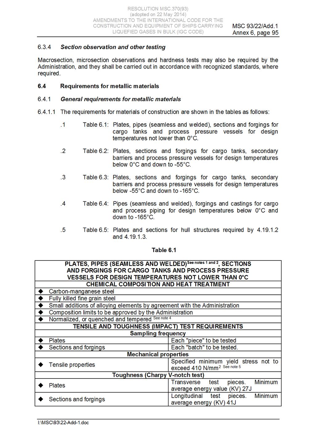
95
96
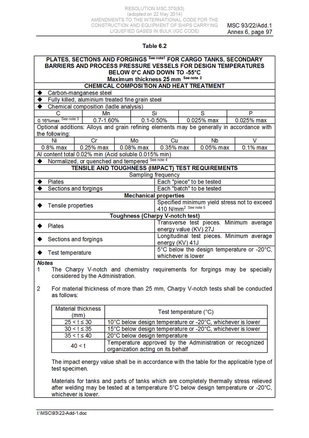
97
98 MSC 93/22/Add.1 Annex 6, page 98 RESOLUTION MSC.370(93) For thermally stress relieved reinforcements and other fittings, the test temperature shall be the same as that required for the adjacent tank-shell thickness. 3 By special agreement with the Administration, the carbon content may be increased to 0.18% maximum, provided the design temperature is not lower than - 4 A controlled rolling procedure or TMCP may be used as an alternative. 5 Materials with specified minimum yield stress exceeding 410 N/mm 2 may be approved by the Administration or recognized organization acting on its behalf. For these materials, particular attention shall be given to the hardness of the welded and heat affected zones. Guidance: For materials exceeding 25 mm in thickness for which the test temperature is - lower, the application of specially treated steels or steels in accordance with table 6.3 may be necessary.
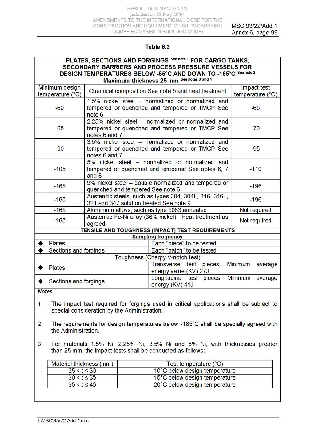
99
100 MSC 93/22/Add.1 Annex 6, page 100 RESOLUTION MSC.370(93) The energy value shall be in accordance with the table for the applicable type of test specimen. For material thickness of more than 40 mm, the Charpy V-notch values shall be specially considered. 4 For 9% Ni steels, austenitic stainless steels and aluminium alloys, thickness greater than 25 mm may be used. 5 The chemical composition limits shall be in accordance with recognized standards. 6 TMCP nickel steels will be subject to acceptance by the Administration. 7 A lower minimum design temperature for quenched and tempered steels may be specially agreed with the Administration. 8 A specially heat treated 5% nickel steel, for example triple heat treated 5% nickel steel, may be used down to The impact test may be omitted, subject to agreement with the Administration.
101
102 MSC 93/22/Add.1 Annex 6, page 102 RESOLUTION MSC.370(93) Table 6.5 PLATES AND SECTIONS FOR HULL STRUCTURES REQUIRED BY AND Minimum design temperature of hull Maximum thickness (mm) for steel grades A B D E AH DH EH FH See note 1 0 and above -5 and above See note 2 Recognized standards down to down to -10 x down to -20 x x x down to -30 x x x 40 x Below -30 In accordance with table 6.2, except that the thickness limitation given in table 6.2 and in note 2 of that table does not apply. Notes "x" means steel grade not to be used. 1 For the purpose of For the purpose of Welding of metallic materials and non-destructive testing General This section shall apply to primary and secondary barriers only, including the inner hull where this forms the secondary barrier. Acceptance testing is specified for carbon, carbon-manganese, nickel alloy and stainless steels, but these tests may be adapted for other materials. At the discretion of the Administration, impact testing of stainless steel and aluminium alloy weldments may be omitted and other tests may be specially required for any material Welding consumables Consumables intended for welding of cargo tanks shall be in accordance with recognized standards. Deposited weld metal tests and butt weld tests shall be required for all consumables. The results obtained from tensile and Charpy V-notch impact tests shall be in accordance with recognized standards. The chemical composition of the deposited weld metal shall be recorded for information Welding procedure tests for cargo tanks and process pressure vessels Welding procedure tests for cargo tanks and process pressure vessels are required for all butt welds The test assemblies shall be representative of:.1 each base material;
103 RESOLUTION MSC.370(93) MSC 93/22/Add.1 Annex 6, page each type of consumable and welding process; and.3 each welding position For butt welds in plates, the test assemblies shall be so prepared that the rolling direction is parallel to the direction of welding. The range of thickness qualified by each welding procedure test shall be in accordance with recognized standards. Radiographic or ultrasonic testing may be performed at the option of the fabricator The following welding procedure tests for cargo tanks and process pressure vessels shall be carried out in accordance with 6.3, with specimens made from each test assembly:.1 cross-weld tensile tests;.2 longitudinal all-weld testing, where required by the recognized standards;.3 transverse bend tests, which may be face, root or side bends. However, longitudinal bend tests may be required in lieu of transverse bend tests in cases where the base material and weld metal have different strength levels;.4 one set of three Charpy V-notch impacts, generally at each of the following locations, as shown in figure 6.2:.1 centreline of the weld;.2 fusion line;.3 1 mm from the fusion line;.4 3 mm from the fusion line; and.5 5 mm from the fusion line; and.5 macrosection, microsection and hardness survey may also be required Each test shall satisfy the following requirements:.1 tensile tests: cross-weld tensile strength shall not be less than the specified minimum tensile strength for the appropriate parent materials. For aluminium alloys, reference shall be made to with regard to the requirements for weld metal strength of under-matched welds (where the weld metal has a lower tensile strength than the parent metal). In every case, the position of fracture shall be recorded for information;.2 a diameter four times the thickness of the test pieces; and.3 Charpy V-notch impact tests: Charpy V-notch tests shall be conducted at the temperature prescribed for the base material being joined. The results of weld metal impact tests, minimum average energy ( KV), shall be no less than 27 J. The weld metal requirements for subsize specimens and single energy values shall be in accordance with The results of fusion line and heat-affected zone impact tests shall show a minimum average energy (KV) in accordance with the transverse or longitudinal requirements of the base material, whichever is applicable, and for subsize specimens, the minimum average energy ( KV) shall be in accordance with If the material thickness does not permit machining either full-size or standard subsize specimens, the testing procedure and acceptance standards shall be in accordance with recognized standards.
104 MSC 93/22/Add.1 Annex 6, page 104 RESOLUTION MSC.370(93) Procedure tests for fillet welding shall be in accordance with recognized standards. In such cases, consumables shall be so selected that exhibit satisfactory impact properties Welding procedure tests for piping Welding procedure tests for piping shall be carried out and shall be similar to those detailed for cargo tanks in Production weld tests For all cargo tanks and process pressure vessels, except integral and membrane tanks, production weld tests shall generally be performed for approximately each 50 m of butt-weld joints and shall be representative of each welding position. For secondary barriers, the same type production tests as required for primary tanks shall be performed, except that the number of tests may be reduced subject to agreement with the Administration. Tests, other than those specified in to may be required for cargo tanks or secondary barriers The production tests for type A and type B independent tanks and semi-membrane tanks shall include bend tests and, where required for procedure tests, one set of three Charpy V-notch tests. The tests shall be made for each 50 m of weld. The Charpy V-notch tests shall be made with specimens having the notch alternately located in the centre of the weld and in the heat-affected zone (most critical location based on procedure qualification results). For austenitic stainless steel, all notches shall be in the centre of the weld For type C independent tanks and process pressure vessels, transverse weld tensile tests are required in addition to the tests listed in Tensile tests shall meet the requirements of The quality assurance/quality control programme shall ensure the continued conformity of the production welds as defined in the material manufacturers quality manual The test requirements for integral and membrane tanks are the same as the applicable test requirements listed in Non-destructive testing All test procedures and acceptance standards shall be in accordance with recognized standards, unless the designer specifies a higher standard in order to meet design assumptions. Radiographic testing shall be used, in principle, to detect internal defects. However, an approved ultrasonic test procedure in lieu of radiographic testing may be conducted, but, in addition, supplementary radiographic testing at selected locations shall be carried out to verify the results. Radiographic and ultrasonic testing records shall be retained For type A independent tanks and semi-membrane tanks, where the design full penetration butt welds of the shell plating of cargo tanks shall be subjected to non-destructive testing suitable to detect internal defects over their full length. Ultrasonic testing in lieu of radiographic testing may be carried out under the same conditions as described in
105 RESOLUTION MSC.370(93) MSC 93/22/Add.1 Annex 6, page 105 way of intersections and at least 10% of the remaining full penetration welds of tank structures shall be subjected to radiographic testing or ultrasonic testing under the same conditions as described in In each case, the remaining tank structure, including the welding of stiffeners and other fittings and attachments, shall be examined by magnetic particle or dye penetrant methods, as considered necessary For type C independent tanks, the extent of non-destructive testing shall be total or partial according to recognized standards, but the controls to be carried out shall not be less than the following:.1 Total non-destructive testing referred to in : Radiographic testing:.1 all butt welds over their full length; Non-destructive testing for surface crack detection:.2 all welds over 10% of their length;.3 reinforcement rings around holes, nozzles, etc., over their full length. As an alternative, ultrasonic testing as described in may be accepted as a partial substitute for the radiographic testing. In addition, the Administration may require total ultrasonic testing on welding of reinforcement rings around holes, nozzles, etc..2 Partial non-destructive testing referred to in : Radiographic testing:.1 all butt-welded crossing joints and at least 10% of the full length of butt welds at selected positions uniformly distributed; Non-destructive testing for surface crack detection:.2 reinforcement rings around holes, nozzles, etc., over their full length; Ultrasonic testing:.3 as may be required by the Administration or recognized organization acting on its behalf in each instance The quality assurance/quality control programme shall ensure the continued conformity of the non-destructive testing of welds, as defined in the material manufacturer's quality manual Inspection of piping shall be carried out in accordance with the requirements of chapter The secondary barrier shall be non-destructive tested for internal defects as considered necessary. Where the outer shell of the hull is part of the secondary barrier, all sheer strake butts and the intersections of all butts and seams in the side shell shall be tested by radiographic testing.
106 MSC 93/22/Add.1 Annex 6, page 106 RESOLUTION MSC.370(93) 6.6 Other requirements for construction in metallic materials General Inspection and non-destructive testing of welds shall be in accordance with the requirements of and Where higher standards or tolerances are assumed in the design, they shall also be satisfied Independent tank For type C tanks and type B tanks primarily constructed of bodies of revolution, the tolerances relating to manufacture, such as out- of-roundness, local deviations from the true form, welded joints alignment and tapering of plates having different thicknesses, shall comply with recognized standards. The tolerances shall also be related to the buckling analysis referred to in and For type C tanks of carbon and carbon-manganese steel, post-weld heat treatment treatment in all other cases and for materials other than those mentioned above shall be to recognized standards. The soaking temperature and holding time shall be to the recognized standards In the case of type C tanks and large cargo pressure vessels of carbon or carbon-manganese steel, for which it is difficult to perform the heat treatment, mechanical stress relieving by pressurizing may be carried out as an alternative to the heat treatment and subject to the following conditions:.1 complicated welded pressure vessel parts such as sumps or domes with nozzles, with adjacent shell plates shall be heat treated before they are welded to larger parts of the pressure vessel;.2 the mechanical stress relieving process shall preferably be carried out during the hydrostatic pressure test required by , by applying a higher pressure than the test pressure required by The pressurizing medium shall be water;.3 for the water temperature, applies;.4 stress relieving shall be performed while the tank is supported by its regular saddles or supporting structure or, when stress relieving cannot be carried out on board, in a manner which will give the same stresses and stress distribution as when supported by its regular saddles or supporting structure;.5 the maximum stress relieving pressure shall be held for 2 h per 25 mm of thickness, but in no case less than 2 h;.6 the upper limits placed on the calculated stress levels during stress relieving shall be the following:.1 equivalent general primary membrane stress: 0.9 R e;.2 equivalent stress composed of primary bending stress plus membrane stress: 1.35 R e, where R e is the specific lower minimum yield stress or 0.2% proof stress at test temperature of the steel used for the tank;
107 RESOLUTION MSC.370(93) MSC 93/22/Add.1 Annex 6, page strain measurements will normally be required to prove these limits for at least the first tank of a series of identical tanks built consecutively. The location of strain gauges shall be included in the mechanical stress relieving procedure to be submitted in accordance with ;.8 the test procedure shall demonstrate that a linear relationship between pressure and strain is achieved at the end of the stress relieving process when the pressure is raised again up to the design pressure;.9 high-stress areas in way of geometrical discontinuities such as nozzles and other openings shall be checked for cracks by dye penetrant or magnetic particle inspection after mechanical stress relieving. Particular attention in this respect shall be paid to plates exceeding 30 mm in thickness;.10 steels which have a ratio of yield stress to ultimate tensile strength greater than 0.8 shall generally not be mechanically stress relieved. If, however, the yield stress is raised by a method giving high ductility of the steel, slightly higher rates may be accepted upon consideration in each case;.11 mechanical stress relieving cannot be substituted for heat treatment of cold formed parts of tanks, if the degree of cold forming exceeds the limit above which heat treatment is required;.12 the thickness of the shell and heads of the tank shall not exceed 40 mm. Higher thicknesses may be accepted for parts which are thermally stress relieved;.13 local buckling shall be guarded against, particularly when tori-spherical heads are used for tanks and domes; and.14 the procedure for mechanical stress relieving shall be to a recognized standard Secondary barriers During construction, the requirements for testing and inspection of secondary barriers shall be approved or accepted by the Administration or recognized organization acting on its behalf (see and ) Semi-membrane tanks For semi-membrane tanks, the relevant requirements in section 6.6 for independent tanks or for membrane tanks shall be applied as appropriate Membrane tanks The quality assurance/quality control programme shall ensure the continued conformity of the weld procedure qualification, design details, materials, construction, inspection and production testing of components. These standards and procedures shall be developed during the prototype testing programme. 6.7 Non-metallic materials General The information in the attached appendix 4 is given for guidance in the selection and use of these materials, based on the experience to date.
108 MSC 93/22/Add.1 Annex 6, page 108 RESOLUTION MSC.370(93) CHAPTER 7 CARGO PRESSURE/TEMPERATURE CONTROL Goal To maintain the cargo tank pressure and temperature within design limits of the containment system and/or carriage requirements of the cargo. 7.1 Methods of control With the exception of tanks designed to withstand full gauge vapour pressure of the cargo under conditions of the upper ambient design temperatures, cargo tanks' pressure and temperature shall be maintained at all times within their design range by either one, or a combination of, the following methods:.1 reliquefaction of cargo vapours;.2 thermal oxidation of vapours;.3 pressure accumulation; and.4 liquid cargo cooling For certain cargoes, where required by chapter 17, the cargo containment system shall be capable of withstanding the full vapour pressure of the cargo under conditions of the upper ambient design temperatures, irrespective of any system provided for dealing with boil-off gas Venting of the cargo to maintain cargo tank pressure and temperature shall not be acceptable except in emergency situations. The Administration may permit certain cargoes to be controlled by venting cargo vapours to the atmosphere at sea. This may also be permitted in port with the authorization of the port Administration. 7.2 Design of systems For normal service, the upper ambient design temperature shall be: - - For service in particularly hot or cold zones, these design temperatures shall be increased or decreased, to the satisfaction of the Administration. The overall capacity of the system shall be such that it can control the pressure within the design conditions without venting to atmosphere. 7.3 Reliquefaction of cargo vapours General The reliquefaction system may be arranged in one of the following ways:.1 a direct system, where evaporated cargo is compressed, condensed and returned to the cargo tanks;.2 an indirect system, where cargo or evaporated cargo is cooled or condensed by refrigerant without being compressed;
109 RESOLUTION MSC.370(93) MSC 93/22/Add.1 Annex 6, page a combined system, where evaporated cargo is compressed and condensed in a cargo/refrigerant heat exchanger and returned to the cargo tanks; and.4 if the reliquefaction system produces a waste stream containing methane during pressure control operations within the design conditions, these waste gases, as far as reasonably practicable, are disposed of without venting to atmosphere. Note: The requirements of chapters 17 and 19 may preclude the use of one or more of these systems or may specify the use of a particular system Compatibility Refrigerants used for reliquefaction shall be compatible with the cargo they may come into contact with. In addition, when several refrigerants are used and may come into contact, they shall be compatible with each other. 7.4 Thermal oxidation of vapours General Maintaining the cargo tank pressure and temperature by means of thermal oxidation of cargo vapours, as defined in and 16.2 shall be permitted only for LNG cargoes. In general:.1 thermal oxidation systems shall exhibit no externally visible flame and shall.2 arrangement of spaces where oxidation systems are located shall comply with 16.3 and supply systems shall comply with 16.4; and.3 if waste gases coming from any other system are to be burnt, the oxidation system shall be designed to accommodate all anticipated feed gas compositions Thermal oxidation systems Thermal oxidation systems shall comply with the following: Burners.1 each thermal oxidation system shall have a separate uptake;.2 each thermal oxidation system shall have a dedicated forced draught system; and.3 combustion chambers and uptakes of thermal oxidation systems shall be designed to prevent any accumulation of gas. Burners shall be designed to maintain stable combustion under all design firing conditions Safety Suitable devices shall be installed and arranged to ensure that gas flow to the burner is cut off unless satisfactory ignition has been established and maintained Each oxidation system shall have provision to manually isolate its gas fuel supply from a safely accessible position.
110 MSC 93/22/Add.1 Annex 6, page 110 RESOLUTION MSC.370(93) Provision shall be made for automatic purging the gas supply piping to the burners by means of an inert gas, after the extinguishing of these burners In case of flame failure of all operating burners for gas or oil or for a combination thereof, the combustion chambers of the oxidation system shall be automatically purged before relighting Arrangements shall be made to enable the combustion chamber to be manually purged. 7.5 Pressure accumulation systems The containment system insulation, design pressure or both shall be adequate to provide for a suitable margin for the operating time and temperatures involved. No additional pressure and temperature control system is required. Conditions for acceptance shall be recorded in the International Certificate of Fitness for the Carriage of Liquefied Gases in Bulk required in Liquid cargo cooling The bulk cargo liquid may be refrigerated by coolant circulated through coils fitted either inside the cargo tank or onto the external surface of the cargo tank. 7.7 Segregation Where two or more cargoes that may react chemically in a dangerous manner are carried simultaneously, separate systems as defined in , each complying with availability criteria as specified in 7.8, shall be provided for each cargo. For simultaneous carriage of two or more cargoes that are not reactive to each other but where, due to properties of their vapour, separate systems are necessary, separation may be by means of isolation valves. 7.8 Availability The availability of the system and its supporting auxiliary services shall be such that:.1 in case of a single failure of a mechanical non-static component or a component of the control systems, the cargo tanks' pressure and temperature can be maintained within their design range without affecting other essential services;.2 redundant piping systems are not required;.3 heat exchangers that are solely necessary for maintaining the pressure and temperature of the cargo tanks within their design ranges shall have a standby heat exchanger, unless they have a capacity in excess of 25% of the largest required capacity for pressure control and they can be repaired on board without external resources. Where an additional and separate method of cargo tank pressure and temperature control is fitted that is not reliant on the sole heat exchanger, then a standby heat exchanger is not required; and.4 for any cargo heating or cooling medium, provisions shall be made to detect the leakage of toxic or flammable vapours into an otherwise non-hazardous area or overboard in accordance with Any vent outlet from this leak detection arrangement shall be to a non-hazardous area and be fitted with a flame screen.
111 RESOLUTION MSC.370(93) MSC 93/22/Add.1 Annex 6, page 111 CHAPTER 8 VENT SYSTEMS FOR CARGO CONTAINMENT Goal To protect cargo containment systems from harmful overpressure or underpressure at all times. 8.1 General All cargo tanks shall be provided with a pressure relief system appropriate to the design of the cargo containment system and the cargo being carried. Hold spaces and interbarrier spaces, which may be subject to pressures beyond their design capabilities, shall also be provided with a suitable pressure relief system. Pressure control systems specified in chapter 7 shall be independent of the pressure relief systems. 8.2 Pressure relief systems Cargo tanks, including deck tanks, shall be fitted with a minimum of two pressure relief valves (PRVs), each being of equal size within manufacturer's tolerances and suitably designed and constructed for the prescribed service Interbarrier spaces shall be provided with pressure relief devices 8. For membrane systems, the designer shall demonstrate adequate sizing of interbarrier space PRVs The setting of the PRVs shall not be higher than the vapour pressure that has been used in the design of the tank. Where two or more PRVs are fitted, valves comprising not more than 50% of the total relieving capacity may be set at a pressure up to 5% above MARVS to allow sequential lifting, minimizing unnecessary release of vapour The following temperature requirements apply to PRVs fitted to pressure relief systems:.1 PRVs on cargo tanks with a design temperature below 0 o C shall be designed and arranged to prevent their becoming inoperative due to ice formation;.2 the effects of ice formation due to ambient temperatures shall be considered in the construction and arrangement of PRVs;.3 Lower melting point materials for internal parts and seals may be accepted, provided that fail-safe operation of the PRV is not compromised; and.4 sensing and exhaust lines on pilot operated relief valves shall be of suitably robust construction to prevent damage. 8 Refer to IACS Unified Interpretation GC9 entitled "Guidance for sizing pressure relief systems for interbarrier spaces", 1988.
112
113 RESOLUTION MSC.370(93) MSC 93/22/Add.1 Annex 6, page Isolation of the PRV shall be carried out under the supervision of the master. This action shall be recorded in the ship's log and a sign posted in the cargo control room, if provided, and at the PRV..4 The tank shall not be loaded until the full relieving capacity is restored Each PRV installed on a cargo tank shall be connected to a venting system, which shall be:.1 so constructed that the discharge will be unimpeded and directed vertically upwards at the exit;.2 arranged to minimize the possibility of water or snow entering the vent system;.3 arranged such that the height of vent exits shall not be less than B/3 or 6 m, whichever is the greater, above the weather deck; and.4 6 m above working areas and walkways Cargo PRV vent exits shall be arranged at a distance at least equal to B or 25 m, whichever is less, from the nearest air intake, outlet or opening to accommodation spaces, service spaces and control stations, or other non-hazardous areas. For ships less than 90 m in length, smaller distances may be permitted All other vent outlets connected to the cargo containment system shall be arranged at a distance of at least 10 m from the nearest air intake, outlet or opening to accommodation spaces, service spaces and control stations, or other non-hazardous areas All other cargo vent outlets not dealt with in other chapters shall be arranged in accordance with , and Means shall be provided to prevent liquid overflow from vent mast outlets, due to hydrostatic pressure from spaces to which they are connected If cargoes that react in a dangerous manner with each other are carried simultaneously, a separate pressure relief system shall be fitted for each one In the vent piping system, means for draining liquid from places where it may accumulate shall be provided. The PRVs and piping shall be arranged so that liquid can, under no circumstances, accumulate in or near the PRVs Suitable protection screens of not more than 13 mm square mesh shall be fitted on vent outlets to prevent the ingress of extraneous objects without adversely affecting the flow. Other requirements for protection screens apply when carrying specific cargoes (see 17.9 and 17.21) All vent piping shall be designed and arranged not to be damaged by the temperature variations to which it may be exposed, forces due to flow or the ship's motions PRVs shall be connected to the highest part of the cargo tank above deck level. PRVs shall be positioned on the cargo tank so that they will remain in the vapour phase at the filling limit (FL where L is defined in
114 MSC 93/22/Add.1 Annex 6, page 114 RESOLUTION MSC.370(93) The adequacy of the vent system fitted on tanks loaded in accordance with shall be demonstrated by the Administration, taking into account the recommendations developed by the Organization 10. A relevant certificate shall be permanently kept on board the ship. For the purposes of this paragraph, vent system means:.1 the tank outlet and the piping to the PRV;.2 the PRV; and.3 the piping from the PRVs to the location of discharge to the atmosphere, including any interconnections and piping that joins other tanks. 8.3 Vacuum protection systems Cargo tanks not designed to withstand a maximum external pressure differential MPa, or tanks that cannot withstand the maximum external pressure differential that can be attained at maximum discharge rates with no vapour return into the cargo tanks, or by operation of a cargo refrigeration system, or by thermal oxidation, shall be fitted with:.1 two independent pressure switches to sequentially alarm and subsequently stop all suction of cargo liquid or vapour from the cargo tank and refrigeration equipment, if fitted, by suitable means at a pressure sufficiently below the maximum external designed pressure differential of the cargo tank; or.2 vacuum relief valves with a gas flow capacity at least equal to the maximum cargo discharge rate per cargo tank, set to open at a pressure sufficiently below the external design differential pressure of the cargo tank Subject to the requirements of chapter 17, the vacuum relief valves shall admit an inert gas, cargo vapour or air to the cargo tank and shall be arranged to minimize the possibility of the entrance of water or snow. If cargo vapour is admitted, it shall be from a source other than the cargo vapour lines The vacuum protection system shall be capable of being tested to ensure that it operates at the prescribed pressure. 8.4 Sizing of pressure relieving system Sizing of pressure relief valves PRVs shall have a combined relieving capacity for each cargo tank to discharge the greater of the following, with not more than a 20% rise in cargo tank pressure above the MARVS: The maximum capacity of the cargo tank inerting system, if the maximum attainable working pressure of the cargo tank inerting system exceeds the MARVS of the cargo tanks; or Vapours generated under fire exposure computed using the following formula: Q = FGA 0.82 (m 3 /s), where: Q = minimum required rate of discharge of air at standard conditions of Kelvin (K) and MPa; 10 Refer to the Guidelines for the evaluation of the adequacy of type C tank vent systems (resolution A.829(19)).
115
116 MSC 93/22/Add.1 Annex 6, page 116 RESOLUTION MSC.370(93) M = molecular mass of the product. The gas factor of each cargo to be carried shall be determined and the highest value shall be used for PRV sizing. A = external surface area of the tank (m 2 ), as defined in , for different tank types, as shown in figure 8.1. Figure 8.1
117
118 MSC 93/22/Add.1 Annex 6, page 118 RESOLUTION MSC.370(93) CHAPTER 9 CARGO CONTAINMENT SYSTEM ATMOSPHERE CONTROL Goal To enable monitoring of the integrity of the containment system and to ensure that the atmosphere within the system and hold spaces is maintained in a safe condition at all times that the ship is in service. 9.1 Atmosphere control within the cargo containment system A piping system shall be arranged to enable each cargo tank to be safely gas-freed, and to be safely filled with cargo vapour from a gas-free condition. The system shall be arranged to minimize the possibility of pockets of gas or air remaining after changing the atmosphere For flammable cargoes, the system shall be designed to eliminate the possibility of a flammable mixture existing in the cargo tank during any part of the atmosphere change operation by utilizing an inerting medium as an intermediate step Piping systems that may contain flammable cargoes shall comply with and A sufficient number of gas sampling points shall be provided for each cargo tank and cargo piping system to adequately monitor the progress of atmosphere change. Gas sampling connections shall be fitted with a single valve above the main deck, sealed with a suitable cap or blank (see ) Inert gas utilized in these procedures may be provided from the shore or from the ship. 9.2 Atmosphere control within the hold spaces (cargo containment systems other than type C independent tanks) Interbarrier and hold spaces associated with cargo containment systems for flammable gases requiring full or partial secondary barriers shall be inerted with a suitable dry inert gas and kept inerted with make-up gas provided by a shipboard inert gas generation system, or by shipboard storage, which shall be sufficient for normal consumption for at least 30 days Alternatively, subject to the restrictions specified in chapter 17, the spaces referred to in requiring only a partial secondary barrier may be filled with dry air provided that the ship maintains a stored charge of inert gas or is fitted with an inert gas generation system sufficient to inert the largest of these spaces, and provided that the configuration of the spaces and the relevant vapour detection systems, together with the capability of the inerting arrangements, ensures that any leakage from the cargo tanks will be rapidly detected and inerting effected before a dangerous condition can develop. Equipment for the provision of sufficient dry air of suitable quality to satisfy the expected demand shall be provided For non-flammable gases, the spaces referred to in and may be maintained with a suitable dry air or inert atmosphere. 9.3 Environmental control of spaces surrounding type C independent tan ks Spaces surrounding cargo tanks that do not have secondary barriers shall be filled with suitable dry inert gas or dry air and be maintained in this condition with make-up inert gas provided by a shipboard inert gas generation system, shipboard storage of inert gas, or with
119 RESOLUTION MSC.370(93) MSC 93/22/Add.1 Annex 6, page 119 dry air provided by suitable air drying equipment. If the cargo is carried at ambient temperature, the requirement for dry air or inert gas is not applicable. 9.4 Inerting Inerting refers to the process of providing a non-combustible environment. Inert gases shall be compatible chemically and operationally at all temperatures likely to occur within the spaces and the cargo. The dew points of the gases shall be taken into consideration Where inert gas is also stored for firefighting purposes, it shall be carried in separate containers and shall not be used for cargo services Where inert gas is stored at temperatures below 0 o C, either as a liquid or as a vapour, the storage and supply system shall be designed so that the temperature of the ship's structure is not reduced below the limiting values imposed on it Arrangements to prevent the backflow of cargo vapour into the inert gas system that are suitable for the cargo carried, shall be provided. If such plants are located in machinery spaces or other spaces outside the cargo area, two non-return valves or equivalent devices and, in addition, a removable spool piece shall be fitted in the inert gas main in the cargo area. When not in use, the inert gas system shall be made separate from the cargo system in the cargo area except for connections to the hold spaces or interbarrier spaces The arrangements shall be such that each space being inerted can be isolated and the necessary controls and relief valves, etc., shall be provided for controlling pressure in these spaces Where insulation spaces are continually supplied with an inert gas as part of a leak detection system, means shall be provided to monitor the quantity of gas being supplied to individual spaces. 9.5 Inert gas production on board The equipment shall be capable of producing inert gas with an oxygen content at no time greater than 5% by volume, subject to the special requirements of chapter 17. A continuous-reading oxygen content meter shall be fitted to the inert gas supply from the equipment and shall be fitted with an alarm set at a maximum of 5% oxygen content by volume, subject to the requirements of chapter An inert gas system shall have pressure controls and monitoring arrangements appropriate to the cargo containment system Spaces containing inert gas generation plants shall have no direct access to accommodation spaces, service spaces or control stations, but may be located in machinery spaces. Inert gas piping shall not pass through accommodation spaces, service spaces or control stations Combustion equipment for generating inert gas shall not be located within the cargo area. Special consideration may be given to the location of inert gas generating equipment using a catalytic combustion process.
120
121
122 MSC 93/22/Add.1 Annex 6, page 122 RESOLUTION MSC.370(93).4 the following regulations of SOLAS chapter II-2 related to tankers do not apply and are replaced by chapters and sections of the Code as detailed below: Regulation: Replaced by: and Chapter Relevant sections in the Code and to ;.5 regulations and shall apply to ships of 500 gross tonnage and over All sources of ignition shall be excluded from spaces where flammable vapour may be present, except as otherwise provided in chapters 10 and The provisions of this section shall apply in conjunction with chapter For the purposes of firefighting, any weather deck areas above cofferdams, ballast or void spaces at the after end of the aftermost hold space or at the forward end of the forwardmost hold space shall be included in the cargo area Fire mains and hydrants Irrespective of size, ships carrying products that are subject to the Code shall comply with the requirements of regulation ll-2/10.2 of the SOLAS Convention, as applicable to cargo ships, except that the required fire pump capacity and fire main and water service pipe diameter shall not be limited by the provisions of regulations ll-2/ and ll-2/ , when a fire pump is used to supply the water-spray system, as permitted by of the Code. The capacity of this fire pump shall be such that these areas can be protected when simultaneously supplying two jets of water from fire hoses with 19 mm nozzles at a pressure of at least 0.5 MPa The arrangements shall be such that at least two jets of water can reach any part of the deck in the cargo area and those portions of the cargo containment system and tank covers that are above the deck. The necessary number of fire hydrants shall be located to satisfy the above arrangements and to comply with the requirements of regulations ll-2/ and ll-2/ of the SOLAS Convention, with hose lengths as specified in regulation ll-2/ In addition, the requirements of regulation ll-2/ shall be met at a pressure of at least 0.5 MPa gauge Stop valves shall be fitted in any crossover provided and in the fire main or mains in a protected location, before entering the cargo area and at intervals ensuring isolation of any damaged single section of the fire main, so that can be complied with using not more than two lengths of hoses from the nearest fire hydrant. The water supply to the fire main serving the cargo area shall be a ring main supplied by the main fire pumps or a single main supplied by fire pumps positioned fore and aft of the cargo area, one of which shall be independently driven.
123
124 MSC 93/22/Add.1 Annex 6, page 124 RESOLUTION MSC.370(93) in and.2 shall cover at least the entire athwartship tank grouping in that area. Any gas process unit(s) included in may be served by an independent section The capacity of the water-spray pumps shall be capable of simultaneous protection of the greater of the following:.1 any two complete athwartship tank groupings, including any gas process units within these areas; or.2 for ships intended for operation as listed in , necessary protection subject to special consideration under of any added fire hazard and the adjacent athwartship tank grouping, in addition to surfaces specified in to Alternatively, the main fire pumps may be used for this service, provided that their total capacity is increased by the amount needed for the water-spray system. In either case, a connection, through a stop valve, shall be made between the fire main and water-spray system main supply line outside the cargo area The boundaries of superstructures and deckhouses normally manned, and lifeboats, liferafts and muster areas facing the cargo area, shall also be capable of being served by one of the fire pumps or the emergency fire pump, if a fire in one compartment could disable both fire pumps Water pumps normally used for other services may be arranged to supply the water-spray system main supply line All pipes, valves, nozzles and other fittings in the water-spray system shall be resistant to corrosion by seawater. Piping, fittings and related components within the cargo be arranged with in-line filters to prevent blockage of pipes and nozzles. In addition, means shall be provided to back-flush the system with fresh water Remote starting of pumps supplying the water-spray system and remote operation of any normally closed valves in the system shall be arranged in suitable locations outside the cargo area, adjacent to the accommodation spaces and readily accessible and operable in the event of fire in the protected areas After installation, the pipes, valves, fittings and assembled system shall be subject to a tightness and function test Dry chemical powder fire-extinguishing systems Ships in which the carriage of flammable products is intended shall be fitted with fixed dry chemical powder fire-extinguishing systems, approved by the Administration based on the guidelines developed by the Organization 14, for the purpose of firefighting on the deck in the cargo area, including any cargo liquid and vapour discharge and loading connections on deck and bow or stern cargo handling areas, as applicable The system shall be capable of delivering powder from at least two hand hose lines, or a combination of monitor/hand hose lines, to any part of the exposed cargo liquid and vapour piping, load/unload connection and exposed gas process units. 14 Refer to the Guidelines for the approval of fixed dry chemical powder fire protection of ships carrying liquefied gases in bulk(msc.1/circ.1315). -extinguishing systems for the
125
126
127 RESOLUTION MSC.370(93) MSC 93/22/Add.1 Annex 6, page Ventilation ducts, air intakes and exhaust outlets serving artificial ventilation systems shall be positioned in accordance with recognized standards Ventilation ducts serving hazardous areas shall not be led through accommodation, service and machinery spaces or control stations, except as allowed in chapter Electric motors' driving fans shall be placed outside the ventilation ducts that may contain flammable vapours. Ventilation fans shall not produce a source of ignition in either the ventilated space or the ventilation system associated with the space. For hazardous areas, ventilation fans and ducts, adjacent to the fans, shall be of non-sparking construction, as defined below:.1 impellers or housing of non-metallic construction, with due regard being paid to the elimination of static electricity;.2 impellers and housing of non-ferrous materials;.3 impellers and housing of austenitic stainless steel; and.4 ferrous impellers and housing with design tip clearance of not less than 13 mm. Any combination of an aluminium or magnesium alloy fixed or rotating component and a ferrous fixed or rotating component, regardless of tip clearance, is considered a sparking hazard and shall not be used in these places Where fans are required by this chapter, full required ventilation capacity for each space shall be available after failure of any single fan, or spare parts shall be provided comprising a motor, starter spares and complete rotating element, including bearings of each type Protection screens of not more than 13 mm square mesh shall be fitted to outside openings of ventilation ducts Where spaces are protected by pressurization, the ventilation shall be designed and installed in accordance with recognized standards Spaces not normally entered Enclosed spaces where cargo vapours may accumulate shall be capable of being ventilated to ensure a safe environment when entry into them is necessary. This shall be capable of being achieved without the need for prior entry For permanent installations, the capacity of 8 air changes per hour shall be provided and for portable systems, the capacity of 16 air changes per hour Fans or blowers shall be clear of personnel access openings, and shall comply with Refer to the recommendation published by the International Electrotechnical Commission, in particular, to publication IEC :1999. Refer to the recommendation published by the International Electrotechnical Commission, in particular, to publication IEC :1999.
128 MSC 93/22/Add.1 Annex 6, page 128 RESOLUTION MSC.370(93) CHAPTER 13 INSTRUMENTATION AND AUTOMATION SYSTEMS Goal To ensure that the instrumentation and automation systems provides for the safe carriage, handling and conditioning of cargo liquid and vapour General Each cargo tank shall be provided with a means for indicating level, pressure and temperature of the cargo. Pressure gauges and temperature indicating devices shall be installed in the liquid and vapour piping systems, in cargo refrigeration installations If loading and unloading of the ship is performed by means of remotely controlled valves and pumps, all controls and indicators associated with a given cargo tank shall be concentrated in one control position Instruments shall be tested to ensure reliability under the working conditions, and recalibrated at regular intervals. Test procedures for instruments and the intervals between recalibration shall be in accordance with manufacturer's recommendations Level indicators for cargo tanks Each cargo tank shall be fitted with liquid level gauging device(s), arranged to ensure that a level reading is always obtainable whenever the cargo tank is operational. The device(s) shall be designed to operate throughout the design pressure range of the cargo tank and at temperatures within the cargo operating temperature range Where only one liquid level gauge is fitted, it shall be arranged so that it can be maintained in an operational condition without the need to empty or gas-free the tank Cargo tank liquid level gauges may be of the following types, subject to special requirements for particular cargoes shown in column "g" in the table of chapter 19:.1 indirect devices, which determine the amount of cargo by means such as weighing or in-line flow metering;.2 closed devices which do not penetrate the cargo tank, such as devices using radio-isotopes or ultrasonic devices;.3 closed devices which penetrate the cargo tank, but which form part of a closed system and keep the cargo from being released, such as float type systems, electronic probes, magnetic probes and bubble tube indicators. If closed gauging device is not mounted directly onto the tank, it shall be provided with a shutoff valve located as close as possible to the tank; and.4 restricted devices which penetrate the tank and, when in use, permit a small quantity of cargo vapour or liquid to escape to the atmosphere, such as fixed tube and slip tube gauges. When not in use, the devices shall be kept completely closed. The design and installation shall ensure that no dangerous escape of cargo can take place when opening the device. Such gauging devices shall be so designed that the maximum opening does not exceed 1.5 mm diameter or equivalent area, unless the device is provided with an excess flow valve.
129 RESOLUTION MSC.370(93) MSC 93/22/Add.1 Annex 6, page Overflow control Except as provided in , each cargo tank shall be fitted with a high liquid level alarm operating independently of other liquid level indicators and giving an audible and visual warning when activated An additional sensor operating independently of the high liquid level alarm shall automatically actuate a shutoff valve in a manner that will both avoid excessive liquid pressure in the loading line and prevent the tank from becoming liquid full The emergency shutdown valve referred to in 5.5 and may be used for this purpose. If another valve is used for this purpose, the same information as referred to in shall be available on board. During loading, whenever the use of these valves may possibly create a potential excess pressure surge in the loading system, alternative arrangements such as limiting the loading rate shall be used A high liquid level alarm and automatic shut-off of cargo tank filling need not be required, when the cargo tank:.1 is a pressure tank with a volume not more than 200 m 3 ; or.2 is designed to withstand the maximum possible pressure during the loading operation, and such pressure is below that of the set pressure of the cargo tank relief valve The position of the sensors in the tank shall be capable of being verified before commissioning. At the first occasion of full loading after delivery and after each dry-docking, testing of high-level alarms shall be conducted by raising the cargo liquid level in the cargo tank to the alarm point All elements of the level alarms, including the electrical circuit and the sensor(s), of the high, and overfill alarms, shall be capable of being functionally tested. Systems shall be tested prior to cargo operation in accordance with Where arrangements are provided for overriding the overflow control system, they shall be such that inadvertent operation is prevented. When this override is operated, continuous visual indication shall be given at the relevant control station(s) and the navigation bridge Pressure monitoring The vapour space of each cargo tank shall be provided with a direct reading gauge. Additionally, an indirect indication shall be provided at the control position required by Maximum and minimum allowable pressures shall be clearly indicated A high-pressure alarm and, if vacuum protection is required, a low-pressure alarm shall be provided on the navigation bridge and at the control position required by Alarms shall be activated before the set pressures are reached For cargo tanks fitted with PRVs which can be set at more than one set pressure in accordance with 8.2.7, high-pressure alarms shall be provided for each set pressure Each cargo-pump discharge line and each liquid and vapour cargo manifold shall be provided with at least one pressure indicator Local-reading manifold pressure indication shall be provided to indicate the pressure between ship's manifold valves and hose connections to the shore.
130
131 RESOLUTION MSC.370(93) MSC 93/22/Add.1 Annex 6, page Where indicated in column "f" in the table of chapter 19 ships certified for carriage of non-flammable products, oxygen deficiency monitoring shall be fitted in cargo machinery spaces and cargo tank hold spaces. Furthermore, oxygen deficiency monitoring equipment shall be installed in enclosed or semi-enclosed spaces containing equipment that may cause an oxygen-deficient environment such as nitrogen generators, inert gas generators or nitrogen cycle refrigerant systems In the case of toxic products or both toxic and flammable products, except when column "i" in the table of chapter 19 refers to , portable equipment can be used for the detection of toxic products as an alternative to a permanently installed system. This equipment shall be used prior to personnel entering the spaces listed in and at 30-minute intervals while they remain in the space In the case of gases classified as toxic products, hold spaces and interbarrier spaces shall be provided with a permanently installed piping system for obtaining gas samples from the spaces. Gas from these spaces shall be sampled and analysed from each sampling head location Permanently installed gas detection shall be of the continuous detection type, capable of immediate response. Where not used to activate safety shutdown functions required by and chapter 16, sampling type detection may be accepted When sampling type gas detection equipment is used, the following requirements shall be met:.1 the gas detection equipment shall be capable of sampling and analysing for each sampling head location sequentially at intervals not exceeding 30 min;.2 individual sampling lines from sampling heads to the detection equipment shall be fitted; and.3 pipe runs from sampling heads shall not be led through non-hazardous spaces except as permitted by The gas detection equipment may be located in a non-hazardous space, provided that the detection equipment such as sample piping, sample pumps, solenoids and analysing units are located in a fully enclosed steel cabinet with the door sealed by a gasket. The atmosphere within the enclosure shall be continuously monitored. At gas concentrations above 30% lower flammable limit (LFL) inside the enclosure, the gas detection equipment shall be automatically shut down Where the enclosure cannot be arranged directly on the forward bulkhead, sample pipes shall be of steel or equivalent material and be routed on their shortest way. Detachable connections, except for the connection points for isolating valves required in and analysing units, are not permitted When gas sampling equipment is located in a non-hazardous space, a flame arrester and a manual isolating valve shall be fitted in each of the gas sampling lines. The isolating valve shall be fitted on the non-hazardous side. Bulkhead penetrations of sample pipes between hazardous and non-hazardous areas shall maintain the integrity of the division penetrated. The exhaust gas shall be discharged to the open air in a non-hazardous area.
132 MSC 93/22/Add.1 Annex 6, page 132 RESOLUTION MSC.370(93) In every installation, the number and the positions of detection heads shall be determined with due regard to the size and layout of the compartment, the compositions and densities of the products intended to be carried and the dilution from compartment purging or ventilation and stagnant areas Any alarms status within a gas detection system required by this section shall initiate an audible and visible alarm:.1 on the navigation bridge;.2 at the relevant control station(s) where continuous monitoring of the gas levels is recorded; and.3 at the gas detector readout location In the case of flammable products, the gas detection equipment provided for hold spaces and interbarrier spaces that are required to be inerted shall be capable of measuring gas concentrations of 0% to 100% by volume Alarms shall be activated when the vapour concentration by volume reaches the equivalent of 30% LFL in air For membrane containment systems, the primary and secondary insulation spaces shall be able to be inerted and their gas content analysed individually 18. The alarm in the secondary insulation space shall be set in accordance with , that in the primary space is set at a value approved by the Administration or recognized organization acting on its behalf For other spaces described by , alarms shall be activated when the vapour concentration reaches 30% LFL and safety functions required by chapter 16 shall be activated before the vapour concentration reaches 60% LFL. The crankcases of internal combustion engines that can run on gas shall be arranged to alarm before 100% LFL Gas detection equipment shall be so designed that it may readily be tested. Testing and calibration shall be carried out at regular intervals. Suitable equipment for this purpose shall be carried on board and be used in accordance with the manufacturer's recommendations. Permanent connections for such test equipment shall be fitted Every ship shall be provided with at least two sets of portable gas detection equipment that meet the requirement of or an acceptable national or international standard A suitable instrument for the measurement of oxygen levels in inert atmospheres shall be provided Additional requirements for containment systems requiring a secondary barrier Integrity of barriers Where a secondary barrier is required, permanently installed instrumentation shall be provided to detect when the primary barrier fails to be liquid-tight at any location or when liquid cargo is in contact with the secondary barrier at any location. This instrumentation shall consist of appropriate gas detecting devices according to However, the instrumentation need not be capable of locating the area where liquid cargo leaks through the primary barrier or where liquid cargo is in contact with the secondary barrier. 18 Gas Concentrations in the Insulation Spaces of Membrane LNG Carriers, March 2007 (published by SIGTTO).

133
134
135
136 MSC 93/22/Add.1 Annex 6, page 136 RESOLUTION MSC.370(93) One or more suitably marked decontamination showers and eyewash stations shall be available on deck, taking into account the size and layout of the ship. The showers and eyewashes shall be operable in all ambient conditions The protective clothing required under shall be gastight. CHAPTER 15 FILLING LIMITS FOR CARGO TANKS Goal To determine the maximum quantity of cargo that can be loaded Definitions Filling limit (FL) means the maximum liquid volume in a cargo tank relative to the total tank volume when the liquid cargo has reached the reference temperature Loading limit (LL) means the maximum allowable liquid volume relative to the tank volume to which the tank may be loaded Reference temperature means (for the purposes of this chapter only):.1 when no cargo vapour pressure/temperature control, as referred to in chapter 7, is provided, the temperature corresponding to the vapour pressure of the cargo at the set pressure of the PRVs; and.2 when a cargo vapour pressure/temperature control, as referred to in chapter 7, is provided, the temperature of the cargo upon termination of loading, during transport or at unloading, whichever is the greatest Ambient design temperature for unrestricted service means sea temperature of accepted by the Administration for ships operating in restricted areas or on voyages of restricted duration, and account may be taken in such cases of any insulation of the tanks. Conversely, higher values of these temperatures may be required for ships permanently operating in areas of high-ambient temperature General requirements The maximum filling limit of cargo tanks shall be so determined that the vapour space has a minimum volume at reference temperature allowing for:.1 tolerance of instrumentation such as level and temperature gauges;.2 volumetric expansion of the cargo between the PRV set pressure and the maximum allowable rise stated in 8.4; and.3 an operational margin to account for liquid drained back to cargo tanks after completion of loading, operator reaction time and closing time of valves, see 5.5 and
137
138 MSC 93/22/Add.1 Annex 6, page 138 RESOLUTION MSC.370(93) 15.6 Information to be provided to the master A document shall be provided to the ship, specifying the maximum allowable loading limits for each cargo tank and product, at each applicable loading temperature and maximum reference temperature. The information in this document shall be approved by the Administration or recognized organization acting on its behalf Pressures at which the PRVs have been set shall also be stated in the document A copy of the above document shall be permanently kept on board by the master. CHAPTER 16 USE OF CARGO AS FUEL Goal To ensure the safe use of cargo as fuel General Except as provided for in 16.9, methane (LNG) is the only cargo whose vapour or boil-off gas may be utilized in machinery spaces of category A, and, in these spaces, it may be utilized only in systems such as boilers, inert gas generators, internal combustion engines, gas combustion unit and gas turbines Use of cargo vapour as fuel This section addresses the use of cargo vapour as fuel in systems such as boilers, inert gas generators, internal combustion engines, gas combustion units and gas turbines For vaporized LNG, the fuel supply system shall comply with the requirements of , and For vaporized LNG, gas consumers shall exhibit no visible flame and shall maintain 16.3 Arrangement of spaces containing gas consumers Spaces in which gas consumers are located shall be fitted with a mechanical ventilation system that is arranged to avoid areas where gas may accumulate, taking into account the density of the vapour and potential ignition sources. The ventilation system shall be separated from those serving other spaces Gas detectors shall be fitted in these spaces, particularly where air circulation is reduced. The gas detection system shall comply with the requirements of chapter Electrical equipment located in the double wall pipe or duct specified in shall comply with the requirements of chapter All vents and bleed lines that may contain or be contaminated by gas fuel shall be routed to a safe location external to the machinery space and be fitted with a flame screen.
139 RESOLUTION MSC.370(93) MSC 93/22/Add.1 Annex 6, page Gas fuel supply General The requirements of this section shall apply to gas fuel supply piping outside of the cargo area. Fuel piping shall not pass through accommodation spaces, service spaces, electrical equipment rooms or control stations. The routeing of the pipeline shall take into account potential hazards, due to mechanical damage, in areas such as stores or machinery handling areas Provision shall be made for inerting and gas-freeing that portion of the gas fuel piping systems located in the machinery space Leak detection Continuous monitoring and alarms shall be provided to indicate a leak in the piping system in enclosed spaces and shut down the relevant gas fuel supply Routeing of fuel supply pipes Fuel piping may pass through or extend into enclosed spaces other than those mentioned in , provided it fulfils one of the following conditions:.1 it is of a double-wall design with the space between the concentric pipes pressurized with inert gas at a pressure greater than the gas fuel pressure. The master gas fuel valve, as required by , closes automatically upon loss of inert gas pressure; or.2 it is installed in a pipe or duct equipped with mechanical exhaust ventilation having a capacity of at least 30 air changes per hour and is arranged to maintain a pressure less than the atmospheric pressure. The mechanical ventilation is in accordance with chapter 12, as applicable. The ventilation is always in operation when there is fuel in the piping and the master gas fuel valve, as required by , closes automatically if the required air flow is not established and maintained by the exhaust ventilation system. The inlet or the duct may be from a non-hazardous machinery space, and the ventilation outlet is in a safe location Requirements for gas fuel with pressure greater than 1 MPa Fuel delivery lines between the high-pressure fuel pumps/compressors and consumers shall be protected with a double-walled piping system capable of containing a high pressure line failure, taking into account the effects of both pressure and low temperature. A single-walled pipe in the cargo area up to the isolating valve(s) required by is acceptable The arrangement in may also be acceptable providing the pipe or trunk is capable of containing a high pressure line failure, according to the requirements of and taking into account the effects of both pressure and possible low temperature and providing both inlet and exhaust of the outer pipe or trunk are in the cargo area.
140 MSC 93/22/Add.1 Annex 6, page 140 RESOLUTION MSC.370(93) Gas consumer isolation The supply piping of each gas consumer unit shall be provided with gas fuel isolation by automatic double block and bleed, vented to a safe location, under both normal and emergency operation. The automatic valves shall be arranged to fail to the closed position on loss of actuating power. In a space containing multiple consumers, the shutdown of one shall not affect the gas supply to the others Spaces containing gas consumers It shall be possible to isolate the gas fuel supply to each individual space containing a gas consumer(s) or through which fuel gas supply piping is run, with an individual master valve, which is located within the cargo area. The isolation of gas fuel supply to a space shall not affect the gas supply to other spaces containing gas consumers if they are located in two or more spaces, and it shall not cause loss of propulsion or electrical power If the double barrier around the gas supply system is not continuous due to air inlets or other openings, or if there is any point where single failure will cause leakage into the space, the individual master valve for the space shall operate under the following circumstances:.1 automatically by:.1 gas detection within the space;.2 leak detection in the annular space of a double-walled pipe;.3 leak detection in other compartments inside the space, containing single-walled gas piping;.4 loss of ventilation in the annular space of a double-walled pipe; and.5 loss of ventilation in other compartments inside the space, containing single-walled gas piping; and.2 manually from within the space, and at least one remote location If the double barrier around the gas supply system is continuous, an individual master valve located in the cargo area may be provided for each gas consumer inside the space. The individual master valve shall operate under the following circumstances:.1 automatically by:.1 leak detection in the annular space of a double-walled pipe served by that individual master valve;.2 leak detection in other compartments containing single-walled gas piping that is part of the supply system served by the individual master valve; and.3 loss of ventilation or loss of pressure in the annular space of a double-walled pipe; and.2 manually from within the space, and at least one remote location.
141 RESOLUTION MSC.370(93) MSC 93/22/Add.1 Annex 6, page Piping and ducting construction Gas fuel piping in machinery spaces shall comply with 5.1 to 5.9, as applicable. The piping shall, as far as practicable, have welded joints. Those parts of the gas fuel piping that are not enclosed in a ventilated pipe or duct according to , and are on the weather decks outside the cargo area, shall have full penetration butt-welded joints and shall be fully radiographed Gas detection Gas detection systems provided in accordance with the requirements of this chapter shall activate the alarm at 30% LFL and shut down the master gas fuel valve required by at not more than 60% LFL (see ) Gas fuel plant and related storage tanks Provision of gas fuel All equipment (heaters, compressors, vaporizers, filters, etc.) for conditioning the cargo and/or cargo boil off vapour for its use as fuel, and any related storage tanks, shall be located in the cargo area. If the equipment is in an enclosed space, the space shall be ventilated according to 12.1 and be equipped with a fixed fire-extinguishing system, according to 11.5, and with a gas detection system according to 13.6, as applicable Remote stops All rotating equipment utilized for conditioning the cargo for its use as fuel shall be arranged for manual remote stop from the engine-room. Additional remote stops shall be located in areas that are always easily accessible, typically cargo control room, navigation bridge and fire control station The fuel supply equipment shall be automatically stopped in the case of low suction pressure or fire detection. Unless expressly provided otherwise, the requirements of need not apply to gas fuel compressors or pumps when used to supply gas consumers Heating and cooling mediums If the heating or cooling medium for the gas fuel conditioning system is returned to spaces outside the cargo area, provisions shall be made to detect and alarm the presence of cargo/cargo vapour in the medium. Any vent outlet shall be in a safe position and fitted with an effective flame screen of an approved type Piping and pressure vessels Piping or pressure vessels fitted in the gas fuel supply system shall comply with chapter Special requirements for main boilers Arrangements Each boiler shall have a separate exhaust uptake Each boiler shall have a dedicated forced draught system. A crossover between boiler force draught systems may be fitted for emergency use providing that any relevant safety functions are maintained Combustion chambers and uptakes of boilers shall be designed to prevent any accumulation of gaseous fuel.
142 MSC 93/22/Add.1 Annex 6, page 142 RESOLUTION MSC.370(93) Combustion equipment The burner systems shall be of dual type, suitable to burn either: oil fuel or gas fuel alone, or oil and gas fuel simultaneously Burners shall be designed to maintain stable combustion under all firing conditions An automatic system shall be fitted to change over from gas fuel operation to oil fuel operation without interruption of the boiler firing, in the event of loss of gas fuel supply Gas nozzles and the burner control system shall be configured such that gas fuel can only be ignited by an established oil fuel flame, unless the boiler and combustion equipment is designed and approved by recognized organization to light on gas fuel Safety There shall be arrangements to ensure that gas fuel flow to the burner is automatically cut-off, unless satisfactory ignition has been established and maintained On the pipe of each gas-burner, a manually operated shut-off valve shall be fitted Provisions shall be made for automatically purging the gas supply piping to the burners, by means of an inert gas, after the extinguishing of these burners The automatic fuel changeover system required by shall be monitored with alarms to ensure continuous availability Arrangements shall be made that, in case of flame failure of all operating burners, the combustion chambers of the boilers are automatically purged before relighting Arrangements shall be made to enable the boilers to be manually purged Special requirements for gas-fired internal combustion engines Dual fuel engines are those that employ gas fuel (with pilot oil) and oil fuel. Oil fuels may include distillate and residual fuels. Gas only engines are those that employ gas fuel only Arrangements When gas is supplied in a mixture with air through a common manifold, flame arrestors shall be installed before each cylinder head Each engine shall have its own separate exhaust The exhausts shall be configured to prevent any accumulation of unburnt gaseous fuel Unless designed with the strength to withstand the worst case overpressure due to ignited gas leaks, air inlet manifolds, scavenge spaces, exhaust system and crank cases shall be fitted with suitable pressure relief systems. Pressure relief systems shall lead to a safe location, away from personnel Each engine shall be fitted with vent systems independent of other engines for crankcases, sumps and cooling systems.
143 RESOLUTION MSC.370(93) MSC 93/22/Add.1 Annex 6, page Combustion equipment Prior to admission of gas fuel, correct operation of the pilot oil injection system on each unit shall be verified For a spark ignition engine, if ignition has not been detected by the engine monitoring system within an engine specific time after opening of the gas supply valve, this shall be automatically shut off and the starting sequence terminated. It shall be ensured that any unburnt gas mixture is purged from the exhaust system For dual-fuel engines fitted with a pilot oil injection system, an automatic system shall be fitted to change over from gas fuel operation to oil fuel operation with minimum fluctuation of the engine power In the case of unstable operation on engines with the arrangement in when gas firing, the engine shall automatically change to oil fuel mode Safety During stopping of the engine, the gas fuel shall be automatically shut off before the ignition source Arrangements shall be provided to ensure that there is no unburnt gas fuel in the exhaust gas system prior to ignition Crankcases, sumps, scavenge spaces and cooling system vents shall be provided with gas detection (see ) Provision shall be made within the design of the engine to permit continuous monitoring of possible sources of ignition within the crank case. Instrumentation fitted inside the crankcase shall be in accordance with the requirements of chapter A means shall be provided to monitor and detect poor combustion or misfiring that may lead to unburnt gas fuel in the exhaust system during operation. In the event that it is detected, the gas fuel supply shall be shut down. Instrumentation fitted inside the exhaust system shall be in accordance with the requirements of chapter Special requirements for gas turbine Arrangements Each turbine shall have its own separate exhaust The exhausts shall be appropriately configured to prevent any accumulation of unburnt gas fuel Unless designed with the strength to withstand the worst case overpressure due to ignited gas leaks, pressure relief systems shall be suitably designed and fitted to the exhaust system, taking into consideration explosions due to gas leaks. Pressure relief systems within the exhaust uptakes shall be lead to a non-hazardous location, away from personnel Combustion equipment An automatic system shall be fitted to change over easily and quickly from gas fuel operation to oil fuel operation with minimum fluctuation of the engine power.
144 MSC 93/22/Add.1 Annex 6, page 144 RESOLUTION MSC.370(93) Safety Means shall be provided to monitor and detect poor combustion that may lead to unburnt gas fuel in the exhaust system during operation. In the event that it is detected, the gas fuel supply shall be shut down Each turbine shall be fitted with an automatic shutdown device for high exhaust temperatures Alternative fuels and technologies If acceptable to the Administration, other cargo gases may be used as fuel, providing that the same level of safety as natural gas in this Code is ensured The use of cargoes identified as toxic products shall not be permitted For cargoes other than LNG, the fuel supply system shall comply with the requirements of , , and 16.5, as applicable, and shall include means for preventing condensation of vapour in the system Liquefied gas fuel supply systems shall comply with In addition to the requirements of , both ventilation inlet and outlet shall be in a non-hazardous area external to the machinery space. CHAPTER 17 SPECIAL REQUIREMENTS Goal To set out the additional requirements in respect of specific cargoes General The requirements of this chapter are applicable where reference thereto is made in column "i" in the table of chapter 19. These requirements are additional to the general requirements of the Code Materials of construction Materials that may be exposed to cargo during normal operations shall be resistant to the corrosive action of the gases. In addition, the following materials of construction for cargo tanks and associated pipelines, valves, fittings and other items of equipment normally in direct contact with the cargo liquid or vapour shall not be used for certain products as specified in column "i" in the table of chapter 19:.1 mercury, copper and copper-bearing alloys, and zinc;.2 copper, silver, mercury, magnesium and other acetylide-forming metals;.3 aluminium and aluminium-bearing alloys;.4 copper, copper alloys, zinc and galvanized steel;
145 RESOLUTION MSC.370(93) MSC 93/22/Add.1 Annex 6, page aluminium, copper and alloys of either; and.6 copper and copper-bearing alloys with greater than 1% copper Independent tanks Products shall be carried in independent tanks only Products shall be carried in type C independent tanks, and the requirements of shall apply. The design pressure of the cargo tank shall take into account any padding pressure or vapour discharge unloading pressure Refrigeration systems Only the indirect system described in shall be used For a ship engaged in the carriage of products that readily form dangerous peroxides, recondensed cargo shall not be allowed to form stagnant pockets of uninhibited liquid. This may be achieved either by:.1 using the indirect system described in , with the condenser inside the cargo tank; or.2 using the direct system or combined system described in and.3 respectively, or the indirect system described in with the condenser outside the cargo tank, and designing the condensate system to avoid any places in which liquid could collect and be retained. Where this is impossible, inhibited liquid shall be added upstream of such a place If the ship is to consecutively carry products as specified in with a ballast passage between, all uninhibited liquid shall be removed prior to the ballast voyage. If a second cargo is to be carried between such consecutive cargoes, the reliquefaction system shall be thoroughly drained and purged before loading the second cargo. Purging shall be carried out using either inert gas or vapour from the second cargo, if compatible. Practical steps shall be taken to ensure that polymers or peroxides do not accumulate in the cargo system Cargoes requiring type 1G ship All butt-welded joints in cargo piping exceeding 75 mm in diameter shall be subject to 100% radiography Gas sampling lines shall not be led into or through non-hazardous areas. Alarms referred to in shall be activated when the vapour concentration reaches the threshold limiting value The alternative of using portable gas detection equipment in accordance with shall not be permitted Cargo control rooms shall be located in a non-hazardous area and, additionally, all instrumentation shall be of the indirect type Personnel shall be protected against the effects of a major cargo release by the provision of a space within the accommodation area that is designed and equipped to the satisfaction of the Administration Notwithstanding the requirements in , access to forecastle spaces shall not be permitted through a door facing the cargo area, unless airlock in accordance with 3.6 is provided.
146 MSC 93/22/Add.1 Annex 6, page 146 RESOLUTION MSC.370(93) Notwithstanding the requirements in 3.2.7, access to control rooms and machinery spaces of turret systems shall not be permitted through doors facing the cargo area Exclusion of air from vapour spaces Air shall be removed from cargo tanks and associated piping before loading and, then, subsequently excluded by:.1 introducing inert gas to maintain a positive pressure. Storage or production capacity of the inert gas shall be sufficient to meet normal operating requirements and relief valve leakage. The oxygen content of inert gas shall, at no time, be greater than 0.2% by volume; or.2 control of cargo temperatures such that a positive pressure is maintained at all times Moisture control For gases that are non-flammable and may become corrosive or react dangerously with water, moisture control shall be provided to ensure that cargo tanks are dry before loading and that, during discharge, dry air or cargo vapour is introduced to prevent negative below at atmospheric pressure Inhibition Care shall be taken to ensure that the cargo is sufficiently inhibited to prevent self-reaction (e.g. polymerization or dimerization) at all times during the voyage. Ships shall be provided with a certificate from the manufacturer stating:.1 name and amount of inhibitor added;.2 date inhibitor was added and the normally expected duration of its effectiveness;.3 any temperature limitations affecting the inhibitor; and.4 the action to be taken should the length of the voyage exceed the effective lifetime of the inhibitors Flame screens on vent outlets When carrying a cargo referenced to this section, cargo tank vent outlets shall be provided with readily renewable and effective flame screens or safety heads of an approved type. Due attention shall be paid in the design of flame screens and vent heads, to the possibility of the blockage of these devices by the freezing of cargo vapour or by icing up in adverse weather conditions. Flame screens shall be removed and replaced by protection screens, in accordance with , when carrying cargoes not referenced to this section Maximum allowable quantity of cargo per tank When carrying a cargo referenced to this section, the quantity of the cargo shall not exceed 3,000 m 3 in any one tank.
147 RESOLUTION MSC.370(93) MSC 93/22/Add.1 Annex 6, page Cargo pumps and discharge arrangements The vapour space of cargo tanks equipped with submerged electric motor pumps shall be inerted to a positive pressure prior to loading, during carriage and during unloading of flammable liquids The cargo shall be discharged only by deepwell pumps or by hydraulically operated submerged pumps. These pumps shall be of a type designed to avoid liquid pressure against the shaft gland Inert gas displacement may be used for discharging cargo from type C independent tanks, provided the cargo system is designed for the expected pressure Ammonia Anhydrous ammonia may cause stress corrosion cracking in containment and process systems made of carbon-manganese steel or nickel steel. To minimize the risk of this occurring, measures detailed in to shall be taken, as appropriate Where carbon-manganese steel is used, cargo tanks, process pressure vessels and cargo piping shall be made of fine-grained steel with a specified minimum yield strength not exceeding 355 N/mm 2, and with an actual yield strength not exceeding 440 N/mm 2. One of the following constructional or operational measures shall also be taken:.1 lower strength material with a specified minimum tensile strength not exceeding 410 N/mm 2 shall be used; or.2 cargo tanks, etc., shall be post-weld stress relief heat treated; or.3 carriage temperature shall be maintained, preferably at a temperature close.4 the ammonia shall contain not less than 0.1% w/w water, and the master shall be provided with documentation confirming this If carbon-manganese steels with higher yield properties are used other than those specified in , the completed cargo tanks, piping, etc., shall be given a post-weld stress relief heat treatment Process pressure vessels and piping of the condensate part of the refrigeration system shall be given a post-weld stress relief heat treatment when made of materials mentioned in The tensile and yield properties of the welding consumables shall exceed those of the tank or piping material by the smallest practical amount Nickel steel containing more than 5% nickel and carbon-manganese steel, not complying with the requirements of and , are particularly susceptible to ammonia stress corrosion cracking and shall not be used in containment and piping systems for the carriage of this product Nickel steel containing not more than 5% nickel may be used, provided the carriage temperature complies with the requirements specified in
148 MSC 93/22/Add.1 Annex 6, page 148 RESOLUTION MSC.370(93) To minimize the risk of ammonia stress corrosion cracking, it is advisable to keep the dissolved oxygen content below 2.5 ppm w/w. This can best be achieved by reducing the average oxygen content in the tanks prior to the introduction of liquid ammonia to less than the values given as a function of the carriage temperature T in the table below: 7& -30 and below O 2 (% v/v) Oxygen percentages for intermediate temperatures may be obtained by direct interpolation Chlorine Cargo containment system The capacity of each tank shall not exceed 600 m 3 and the total capacity of all cargo tanks shall not exceed 1,200 m The tank design vapour pressure shall not be less than 1.35 MPa (see and ) Parts of tanks protruding above the upper deck shall be provided with protection against thermal radiation, taking into account total engulfment by fire Each tank shall be provided with two PRVs. A bursting disc of appropriate material shall be installed between the tank and the PRVs. The rupture pressure of the bursting disc shall be 0.1 MPa lower than the opening pressure of the pressure relief valve, which shall be set at the design vapour pressure of the tank but not less than 1.35 MPa gauge. The space between the bursting disc and the relief valve shall be connected through an excess flow valve to a pressure gauge and a gas detection system. Provisions shall be made to keep this space at or near the atmospheric pressure during normal operation Outlets from PRVs shall be arranged in such a way as to minimize the hazards on board the ship as well as to the environment. Leakage from the relief valves shall be led through the absorption plant to reduce the gas concentration as far as possible. The relief valve exhaust line shall be arranged at the forward end of the ship to discharge outboard at deck level with an arrangement to select either port or starboard side, with a mechanical interlock to ensure that one line is always open The Administration and the port Administration may require that chlorine is carried in a refrigerated state at a specified maximum pressure Cargo piping systems Cargo discharge shall be performed by means of compressed chlorine vapour from shore, dry air or another acceptable gas, or fully submerged pumps. Cargo discharge compressors on board ships shall not be used for this. The pressure in the vapour space of the tank during discharging shall not exceed 1.05 MPa gauge.
149
150 MSC 93/22/Add.1 Annex 6, page 150 RESOLUTION MSC.370(93).2 one of the decontamination showers required by shall be located near the weather deck airlock to the space;.3 the space shall be designed to accommodate the entire crew of the ship and be provided with a source of uncontaminated air for a period of not less than 4 h; and.4 one set of oxygen therapy equipment shall be carried in the space Filling limits for cargo tanks The requirements of do not apply when it is intended to carry chlorine The chlorine content of the gas in the vapour space of the cargo tank after loading shall be greater than 80% by volume Ethylene oxide For the carriage of ethylene oxide, the requirements of shall apply, with the additions and modifications as given in this section Deck tanks shall not be used for the carriage of ethylene oxide Stainless steels types 416 and 442, as well as cast iron, shall not be used in ethylene oxide cargo containment and piping systems Before loading, tanks shall be thoroughly and effectively cleaned to remove all traces of previous cargoes from tanks and associated pipework, except where the immediate prior cargo has been ethylene oxide, propylene oxide or mixtures of these products. Particular care shall be taken in the case of ammonia in tanks made of steel other than stainless steel Ethylene oxide shall be discharged only by deepwell pumps or inert gas displacement. The arrangement of pumps shall comply with Ethylene oxide shall be carried refrigerated only and maintained at temperatures PRVs shall be set at a pressure of not less than 0.55 MPa gauge. The maximum set pressure shall be specially approved by the Administration The protective padding of nitrogen gas, as required by , shall be such that the nitrogen concentration in the vapour space of the cargo tank will, at no time, be less than 45% by volume Before loading, and at all times when the cargo tank contains ethylene oxide liquid or vapour, the cargo tank shall be inerted with nitrogen The water-spray system required by and that required by 11.3 shall operate automatically in a fire involving the cargo containment system A jettisoning arrangement shall be provided to allow the emergency discharge of ethylene oxide in the event of uncontrollable self-reaction.
151 RESOLUTION MSC.370(93) MSC 93/22/Add.1 Annex 6, page Separate piping systems Separate piping systems, as defined in , shall be provided Methyl acetylene-propadiene mixtures Methyl acetylene-propadiene mixtures shall be suitably stabilized for transport. Additionally, upper limits of temperatures and pressure during the refrigeration shall be specified for the mixtures Examples of acceptable stabilized compositions are:.1 Composition 1:.1 maximum methyl acetylene to propadiene molar ratio of 3 to 1;.2 maximum combined concentration of methyl acetylene and propadiene of 65 mol%;.3 minimum combined concentration of propane, butane, and isobutane of 24 mol%, of which at least one third (on a molar basis) shall be butanes and one third propane;.4 maximum combined concentration of propylene and butadiene of 10 mol%;.2 Composition 2:.1 maximum methyl acetylene and propadiene combined concentration of 30 mol%;.2 maximum methyl acetylene concentration of 20 mol%;.3 maximum propadiene concentration of 20 mol%;.4 maximum propylene concentration of 45 mol%;.5 maximum butadiene and butylenes combined concentration of 2 mol%;.6 minimum saturated C4 hydrocarbon concentration of 4 mol%; and.7 minimum propane concentration of 25 mol% Other compositions may be accepted, provided the stability of the mixture is demonstrated to the satisfaction of the Administration If a ship has a direct vapour compression refrigeration system, this shall comply with the following requirements, subject to pressure and temperature limitations depending on the composition. For the example compositions given in , the following features shall be provided:.1 a vapour compressor that does not raise the temperature and pressure of the vapour above 60 o C and 1.75 MPa gauge during its operation, and that does not allow vapour to stagnate in the compressor while it continues to run;
152 MSC 93/22/Add.1 Annex 6, page 152 RESOLUTION MSC.370(93).2 discharge piping from each compressor stage or each cylinder in the same stage of a reciprocating compressor shall have:.1 two temperature-actuated shutdown switches set to operate at 60 o C or less;.2 a pressure-actuated shutdown switch set to operate at 1.75 MPa gauge or less; and.3 a safety relief valve set to relieve at 1.8 MPa gauge or less;.3 the relief valve required by.2.3 shall vent to a mast meeting the requirements of , and and shall not relieve into the compressor suction line; and.4 an alarm that sounds in the cargo control position and in the navigation bridge when a high-pressure switch, or a high-temperature switch, operates The piping system, including the cargo refrigeration system, for tanks to be loaded with methyl acetylene-propadiene mixtures shall be either independent (as defined in ) or separate (as defined in ) from piping and refrigeration systems for other tanks. This segregation shall apply to all liquid and vapour vent lines and any other possible connections, such as common inert gas supply lines Nitrogen Materials of construction and ancillary equipment such as insulation shall be resistant to the effects of high oxygen concentrations caused by condensation and enrichment at the low temperatures attained in parts of the cargo system. Due consideration shall be given to ventilation in areas where condensation might occur, to avoid the stratification of oxygen-enriched atmosphere Propylene oxide and mixtures of ethylene oxide-propylene oxide with ethylene oxide content of not more than 30% by weight Products transported under the provisions of this section shall be acetylene-free Unless cargo tanks are properly cleaned, these products shall not be carried in tanks that have contained as one of the three previous cargoes any product known to catalyse polymerization, such as:.1 anhydrous ammonia and ammonia solutions;.2 amines and amine solutions; and.3 oxidizing substances (e.g. chlorine) Before loading, tanks shall be thoroughly and effectively cleaned to remove all traces of previous cargoes from tanks and associated pipework, except where the immediate prior cargo has been propylene oxide or ethylene oxide-propylene oxide mixtures. Particular care shall be taken in the case of ammonia in tanks made of steel other than stainless steel In all cases, the effectiveness of cleaning procedures for tanks and associated pipework shall be checked, by suitable testing or inspection, to ascertain that no traces of acidic or alkaline materials remain that might create a hazardous situation in the presence of these products.
153 RESOLUTION MSC.370(93) MSC 93/22/Add.1 Annex 6, page Tanks shall be entered and inspected prior to each initial loading of these products to ensure freedom from contamination, heavy rust deposits and any visible structural defects. When cargo tanks are in continuous service for these products, such inspections shall be performed at intervals of not more than two years Tanks for the carriage of these products shall be of steel or stainless steel construction Tanks that have contained these products may be used for other cargoes after thorough cleaning of tanks and associated pipework systems by washing or purging All valves, flanges, fittings and accessory equipment shall be of a type suitable for use with these products and shall be constructed of steel or stainless steel in accordance with recognized standards. Disc or disc faces, seats and other wearing parts of valves shall be made of stainless steel containing not less than 11% chromium Gaskets shall be constructed of materials which do not react with, dissolve in, or lower the auto-ignition temperature of, these products and which are fire-resistant and possess adequate mechanical behaviour. The surface presented to the cargo shall be polytetrafluoroethylene (PTFE) or materials giving a similar degree of safety by their inertness. Spirally-wound stainless steel with a filler of PTFE or similar fluorinated polymer may be accepted, if approved by the Administration or recognized organization acting on its behalf Insulation and packing, if used, shall be of a material which does not react with, dissolve in, or lower the auto-ignition temperature of, these products The following materials are generally found unsatisfactory for use in gaskets, packing and similar uses in containment systems for these products and would require testing before being approved:.1 neoprene or natural rubber, if it comes into contact with the products;.2 asbestos or binders used with asbestos; and.3 materials containing oxides of magnesium, such as mineral wools Filling and discharge piping shall extend to within 100 mm of the bottom of the tank or any sump The products shall be loaded and discharged in such a manner that venting of the tanks to atmosphere does not occur. If vapour return to shore is used during tank loading, the vapour return system connected to a containment system for the product shall be independent of all other containment systems During discharging operations, the pressure in the cargo tank shall be maintained above MPa gauge The cargo shall be discharged only by deepwell pumps, hydraulically operated submerged pumps or inert gas displacement. Each cargo pump shall be arranged to ensure that the product does not heat significantly if the discharge line from the pump is shut off or otherwise blocked Tanks carrying these products shall be vented independently of tanks carrying other products. Facilities shall be provided for sampling the tank contents without opening the tank to atmosphere.
154 MSC 93/22/Add.1 Annex 6, page 154 RESOLUTION MSC.370(93) Cargo hoses used for transfer of these products shall be marked "FOR ALKYLENE OXIDE TRANSFER ONLY" Hold spaces shall be monitored for these products. Hold spaces surrounding type A and type B independent tanks shall also be inerted and monitored for oxygen. The oxygen content of these spaces shall be maintained below 2% by volume. Portable sampling equipment is satisfactory Prior to disconnecting shore lines, the pressure in liquid and vapour lines shall be relieved through suitable valves installed at the loading header. Liquid and vapour from these lines shall not be discharged to atmosphere Tanks shall be designed for the maximum pressure expected to be encountered during loading, carriage or unloading of cargo Tanks for the carriage of propylene oxide with a design vapour pressure of less than 0.06 MPa, and tanks for the carriage of ethylene oxide-propylene oxide mixtures with a design vapour pressure of less than 0.12 MPa, shall have a cooling system to maintain the cargo below the reference temperature. The reference temperatures are referred to in Pressure relief valve settings shall not be less than 0.02 MPa gauge; and for type C independent tanks not greater than 0.7 MPa gauge for the carriage of propylene oxide and not greater than 0.53 MPa gauge for the carriage of ethylene oxide-propylene oxide mixtures The piping system for tanks to be loaded with these products shall be completely separate from piping systems for all other tanks, including empty tanks, and from all cargo compressors. If the piping system for the tanks to be loaded with these products is not independent, as defined in , the required piping separation shall be accomplished by the removal of spool pieces, valves, or other pipe sections and the installation of blank flanges at these locations. The required separation applies to all liquid and vapour piping, liquid and vapour vent lines and any other possible connections such as common inert gas supply lines The products shall be transported only in accordance with cargo handling plans approved by the Administration. Each intended loading arrangement shall be shown on a separate cargo handling plan. Cargo handling plans shall show the entire cargo piping system and the locations for installation of the blank flanges needed to meet the above piping separation requirements. A copy of each approved cargo handling plan shall be kept on board the ship. The International Certificate of Fitness for the Carriage of Liquefied Gases in Bulk shall be endorsed to include references to the approved cargo handling plans Before each initial loading of these products, and before every subsequent return to such service, certification verifying that the required piping separation has been achieved shall be obtained from a responsible person acceptable to the port Administration and carried on board the ship. Each connection between a blank flange and pipeline flange shall be fitted with a wire and seal by the responsible person to ensure that inadvertent removal of the blank flange is impossible The maximum allowable loading limits for each tank shall be indicated for each loading temperature that may be applied, in accordance with The cargo shall be carried under a suitable protective padding of nitrogen gas. An automatic nitrogen make-up system shall be installed to prevent the tank pressure falling below MPa gauge in the event of product temperature fall due to ambient conditions or malfunctioning of refrigeration system. Sufficient nitrogen shall be available on board to satisfy the demand of the automatic pressure control. Nitrogen of commercially pure quality (99.9% by
155 RESOLUTION MSC.370(93) MSC 93/22/Add.1 Annex 6, page 155 volume) shall be used for padding. A battery of nitrogen bottles, connected to the cargo tanks through a pressure reduction valve, satisfies the intention of the expression "automatic" in this context The cargo tank vapour space shall be tested prior to and after loading to ensure that the oxygen content is 2% by volume or less A water-spray system of sufficient capacity shall be provided to blanket effectively the area surrounding the loading manifold, the exposed deck piping associated with product handling and the tank domes. The arrangement of piping and nozzles shall be such as to give a uniform distribution rate of 10l/m 2 /min. The arrangement shall ensure that any spilled cargo is washed away The water-spray system shall be capable of local and remote manual operation in case of a fire involving the cargo containment system. Remote manual operation shall be arranged such that the remote starting of pumps supplying the water-spray system and remote operation of any normally closed valves in the system can be carried out from a suitable location outside the cargo area, adjacent to the accommodation spaces and readily accessible and operable in the event of fire in the areas protected When ambient temperatures permit, a pressurized water hose ready for immediate use shall be available during loading and unloading operations, in addition to the above water-spray requirements Vinyl chloride In cases where polymerization of vinyl chloride is prevented by addition of an inhibitor, 17.8 is applicable. In cases where no inhibitor has been added, or the inhibitor concentration is insufficient, any inert gas used for the purposes of 17.6 shall contain no more oxygen than 0.1% by volume. Before loading is started, inert gas samples from the tanks and piping shall be analysed. When vinyl chloride is carried, a positive pressure shall always be maintained in the tanks and during ballast voyages between successive carriages Mixed C4 cargoes Cargoes that may be carried individually under the requirements of this Code, notably butane, butylenes and butadiene, may be carried as mixtures subject to the provisions of this section. These cargoes may variously be referred to as "Crude C4", "Crude butadiene", "Crude steam-cracked C4", "Spent steam-cracked C4", "C4 stream", "C4 raffinate", or may be shipped under a different description. In all cases, the material safety data sheets (MSDS) shall be consulted as the butadiene content of the mixture is of prime concern as it is potentially toxic and reactive. While it is recognized that butadiene has a relatively low vapour pressure, if such mixtures contain butadiene they shall be regarded as toxic and the appropriate precautions applied If the mixed C4 cargo shipped under the terms of this section contains more than 50% (mole) of butadiene, the inhibitor precautions in 17.8 shall apply Unless specific data on liquid expansion coefficients is given for the specific mixture loaded, the filling limit restrictions of chapter 15 shall be calculated as if the cargo contained 100% concentration of the component with the highest expansion ratio.
156 MSC 93/22/Add.1 Annex 6, page 156 RESOLUTION MSC.370(93) Carbon dioxide: high purity Uncontrolled pressure loss from the cargo can cause "sublimation" and the cargo will change from the liquid to the solid state. The precise "triple point" temperature of a particular carbon dioxide cargo shall be supplied before loading the cargo, and will depend on the purity of that cargo, and this shall be taken into account when cargo instrumentation is adjusted. The set pressure for the alarms and automatic actions described in this section shall be set to at least 0.05 MPa above the triple point for the specific cargo being carried There is a potential for the cargo to solidify in the event that a cargo tank relief valve, fitted in accordance with 8.2, fails in the open position. To avoid this, a means of isolating the cargo tank safety valves shall be provided and the requirements of do not apply when carrying this carbon dioxide. Discharge piping from safety relief valves shall be designed so they remain free from obstructions that could cause clogging. Protective screens shall not be fitted to the outlets of relief valve discharge piping, so the requirements of do not apply Discharge piping from safety relief valves are not required to comply with , but shall be designed so they remain free from obstructions that could cause clogging. Protective screens shall not be fitted to the outlets of relief valve discharge piping, so the requirements of do not apply Cargo tanks shall be continuously monitored for low pressure when a carbon dioxide cargo is carried. An audible and visual alarm shall be given at the cargo control position and on the bridge. If the cargo tank pressure continues to fall to within 0.05 MPa of the "triple point" for the particular cargo, the monitoring system shall automatically close all cargo manifold liquid and vapour valves and stop all cargo compressors and cargo pumps. The emergency shutdown system required by may be used for this purpose All materials used in cargo tanks and cargo piping system shall be suitable for the lowest temperature that may occur in service, which is defined as the saturation temperature of the carbon dioxide cargo at the set pressure of the automatic safety system described in Cargo hold spaces, cargo compressor rooms and other enclosed spaces where carbon dioxide could accumulate shall be fitted with continuous monitoring for carbon dioxide build-up. This fixed gas detection system replaces the requirements of 13.6, and hold spaces shall be monitored permanently even if the ship has type C cargo containment Carbon dioxide: reclaimed quality The requirements of also apply to this cargo. In addition, the materials of construction used in the cargo system shall also take account of the possibility of corrosion, in case the reclaimed quality carbon dioxide cargo contains impurities such as water, sulphur dioxide, etc., which can cause acidic corrosion or other problems.
157 RESOLUTION MSC.370(93) MSC 93/22/Add.1 Annex 6, page 157 CHAPTER 18 OPERATING REQUIREMENTS Goal To ensure that all ship staff involved in cargo operations have sufficient information about cargo properties and operating the cargo system so they can conduct cargo operations safely General Those involved in liquefied gas carrier operations shall be made aware of the special requirements associated with, and precautions necessary for, their safe operation A copy of the Code, or national regulations incorporating the provisions of the Code, shall be on board every ship covered by the Code Cargo operations manuals The ship shall be provided with copies of suitably detailed cargo system operation manuals approved by the Administration such that trained personnel can safely operate the ship with due regard to the hazards and properties of the cargoes that are permitted to be carried The content of the manuals shall include, but not be limited to:.1 overall operation of the ship from dry-dock to dry-dock, including procedures for cargo tank cooldown and warm-up, transfer (including ship-to-ship transfer), cargo sampling, gas-freeing, ballasting, tank cleaning and changing cargoes;.2 cargo temperature and pressure control systems;.3 cargo system limitations, including minimum temperatures (cargo system and inner hull), maximum pressures, transfer rates, filling limits and sloshing limitations;.4 nitrogen and inert gas systems;.5 firefighting procedures: operation and maintenance of firefighting systems and use of extinguishing agents;.6 special equipment needed for the safe handling of the particular cargo;.7 fixed and portable gas detection;.8 control, alarm and safety systems;.9 emergency shutdown systems;.10 procedures to change cargo tank pressure relief valve set pressures in accordance with and ; and.11 emergency procedures, including cargo tank relief valve isolation, single tank gas-freeing and entry and emergency ship-to-ship transfer operations.
158 MSC 93/22/Add.1 Annex 6, page 158 RESOLUTION MSC.370(93) 18.3 Cargo information Information shall be on board and available to all concerned in the form of a cargo information data sheet(s) giving the necessary data for the safe carriage of cargo. Such information shall include, for each product carried:.1 a full description of the physical and chemical properties necessary for the safe carriage and containment of the cargo;.2 reactivity with other cargoes that are capable of being carried on board in accordance with the International Certificate of Fitness for the Carriage of Liquefied Gases in Bulk;.3 the actions to be taken in the event of cargo spills or leaks;.4 countermeasures against accidental personal contact;.5 firefighting procedures and firefighting media;.6 special equipment needed for the safe handling of the particular cargo; and.7 emergency procedures The physical data supplied to the master, in accordance with , shall include information regarding the relative cargo density at various temperatures to enable the calculation of cargo tank filling limits in accordance with the requirements of chapter Contingency plans in accordance with , for spillage of cargo carried at ambient temperature, shall take account of potential local temperature reduction such as when the escaped cargo has reduced to atmospheric pressure and the potential effect of this cooling on hull steel Suitability for carriage The master shall ascertain that the quantity and characteristics of each product to be loaded are within the limits indicated in the International Certificate of Fitness for the Carriage of Liquefied Gases in Bulk required by 1.4, and in the Loading and Stability Information booklet required by 2.2.5, and that products are listed in the International Certificate of Fitness for the Carriage of Liquefied Gases in Bulk as required under section 4 of the certificate Care shall be taken to avoid dangerous chemical reactions if cargoes are mixed. This is of particular significance in respect of:.1 tank cleaning procedures required between successive cargoes in the same tank; and.2 simultaneous carriage of cargoes that react when mixed. This shall be permitted only if the complete cargo systems including, but not limited to, cargo pipework, tanks, vent systems and refrigeration systems are separated as defined in Where products are required to be inhibited, the certificate required by 17.8 shall be supplied before departure, otherwise the cargo shall not be transported.
159 RESOLUTION MSC.370(93) MSC 93/22/Add.1 Annex 6, page Carriage of cargo at low temperature When carrying cargoes at low temperatures:.1 the cooldown procedure laid down for that particular tank, piping and ancillary equipment shall be followed closely;.2 loading shall be carried out in such a manner as to ensure that design temperature gradients are not exceeded in any cargo tank, piping or other ancillary equipment; and.3 if provided, the heating arrangements associated with the cargo containment systems shall be operated in such a manner as to ensure that the temperature of the hull structure does not fall below that for which the material is designed Cargo transfer operations A pre-cargo operations meeting shall take place between ship personnel and the persons responsible at the transfer facility. Information exchanged shall include the details of the intended cargo transfer operations and emergency procedures. A recognized industry checklist shall be completed for the intended cargo transfer and effective communications shall be maintained throughout the operation Essential cargo handling controls and alarms shall be checked and tested prior to cargo transfer operations Personnel training Personnel shall be adequately trained in the operational and safety aspects of liquefied gas carriers as required by the International Convention on Standards of Training, Certification and Watchkeeping for Seafarers, 1978, as amended, the International Safety Management Code and the Medical First Aid Guide (MFAG). As a minimum:.1 all personnel shall be adequately trained in the use of protective equipment provided on board and have basic training in the procedures, appropriate to their duties, necessary under emergency conditions; and.2 officers shall be trained in emergency procedures to deal with conditions of leakage, spillage or fire involving the cargo and a sufficient number of them shall be instructed and trained in essential first aid for the cargoes carried Entry into enclosed spaces Under normal operational circumstances, personnel shall not enter cargo tanks, hold spaces, void spaces or other enclosed spaces where gas may accumulate, unless the gas content of the atmosphere in such space is determined by means of fixed or portable equipment to ensure oxygen sufficiency and the absence of toxic atmosphere If it is necessary to gas-free and aerate a hold space surrounding a type A cargo tank for routine inspection, and flammable cargo is carried in the cargo tank, the inspection shall be conducted when the tank contains only the minimum amount of cargo "heel" to keep the cargo tank cold. The hold shall be re-inerted as soon as the inspection is completed. 21 Refer to the Revised recommendations for entering enclosed spaces aboard ships Organization by resolution A.1050(27)., adopted by the
160
161 RESOLUTION MSC.370(93) MSC 93/22/Add.1 Annex 6, page ESD valves shall be remotely operated, be of the fail-closed type (closed on loss of actuating power), be capable of local manual closure and have positive indication of the actual valve position. As an alternative to the local manual closing of the ESD valve, a manually operated shut-off valve in series with the ESD valve shall be permitted. The manual valve shall be located adjacent to the ESD valve. Provisions shall be made to handle trapped liquid should the ESD valve close while the manual valve is also closed ESD valves in liquid piping systems shall close fully and smoothly within 30 s of actuation. Information about the closure time of the valves and their operating characteristics shall be available on board, and the closing time shall be verifiable and repeatable The closing time of the valve referred to in to (i.e. time from shutdown signal initiation to complete valve closure) shall not be greater than: (second) where: U = ullage volume at operating signal level (m 3 ); LR = maximum loading rate agreed between ship and shore facility (m 3 /h). The loading rate shall be adjusted to limit surge pressure on valve closure to an acceptable level, taking into account the loading hose or arm, the ship and the shore piping systems, where relevant Ship-shore and ship-ship manifold connections One ESD valve shall be provided at each manifold connection. Cargo manifold connections not being used for transfer operations shall be blanked with blank flanges rated for the design pressure of the pipeline system Cargo system valves If cargo system valves as defined in section 5.5 are also ESD valves within the meaning of 18.10, then the requirements of shall apply ESD system controls As a minimum, the ESD system shall be capable of manual operation by a single control on the bridge and either in the control position required by or the cargo control room, if installed, and no less than two locations in the cargo area The ESD system shall be automatically activated on detection of a fire on the weather decks of the cargo area and/or cargo machinery spaces. As a minimum, the method of detection used on the weather decks shall cover the liquid and vapour domes of the cargo tanks, the cargo manifolds and areas where liquid piping is dismantled regularly. Detection and Cargo machinery that is running shall be stopped by activation of the ESD system in accordance with the cause and effect matrix in table 18.1.
162
163
164 MSC 93/22/Add.1 Annex 6, page 164 RESOLUTION MSC.370(93) CHAPTER 19 SUMMARY OF MINIMUM REQUIREMENTS Explanatory notes to the summary of minimum requirements Product name (column a) (column b) Ship type (column c) Independent tank type C required (column d) Tank environmental control (column e) Vapour detection (column f) Gauging (column g) (column h) Special requirements (column i) Refrigerant gases The product name shall be used in the shipping document for any cargo offered for bulk shipments. Any additional name may be included in brackets after the product name. In some cases, the product names are not identical with the names given in previous issues of the Code. Deleted 1: Ship type 1G ( ) 2: Ship type 2G ( ) 3: Ship type 2PG ( ) 4: Ship type 3G ( ) Type C independent tank (4.23) Inert: Inerting (9.4) Dry: Drying (17.7) - : No special requirements under the Code F: Flammable vapour detection T: Toxic vapour detection F+T: Flammable and toxic vapour detection A: Asphixiant I: Indirect or closed ( and.2) R: Indirect, closed or restricted ( ,.2,.3 and.4) C: Indirect or closed ( ,.2 and.3) Deleted When specific reference is made to chapters 14 and/or 17, these requirements shall be additional to the requirements in any other column. Non-toxic and non-flammable gases Unless otherwise specified, gas mixtures containing less than 5% total acetylenes may be transported with no further requirements than those provided for the major components.
165
166
167
168 MSC 93/22/Add.1 Annex 6, page 168 RESOLUTION MSC.370(93) APPENDIX 1 IGC CODE PRODUCT DATA REPORTING FORM Characteristics of products proposed for transport on the IGC Code ships 1 P RODUCT IDENTITY Product name The product name should be used in the shipping document for any cargo offered for bulk shipments. Any additional name may be included in brackets after the product name. 1.1 Other names and identification numbers Main trade name : Main chemical name : Chemical formula : C.A.S number : EHS number : BMR number : RTECS number : 1.2 Associated synonyms Structure Synonym name Type 1.3 Composition Component name % Type
169 RESOLUTION MSC.370(93) MSC 93/22/Add.1 Annex 6, page Physical properties Property Units Qual Lower Upper Reference/ value value comments Molecular weight (kg/m 3 ) Flash point (c.c.) Boiling point Water solubility at 20 (mg/l) (Pa) Auto-ignition temperature Explosion limits MESG (% v/v) (mm) 3 Relevant chemical properties Water reactivity (0-2) 0 = No reactivity Details 1 = Reactive 2 = Highly Does the product react with air to cause a potentially hazardous situation (Y/N) If so, provide details Reference Is an inhibitor or stabilizer needed to prevent a hazardous reaction? (Y/N) If so, provide details Reference
170 MSC 93/22/Add.1 Annex 6, page 170 RESOLUTION MSC.370(93) 4 Mammalian toxicity 4.1 Acute toxicity Qual Lower value Upper value Species Reference/ comments Oral LD 50 (mg/kg) Dermal LD 50 (mg/kg) Inhalation LD 50 (mg/l/4h) 4.2 Corrosivity and irritation Skin corrosion time Units Qual. Lower Upper Reference/ Value Value Comments (hours) Skin irritation (4-hour exposure) Resultant observation Species Reference/ Comments Eye irritation Not irritating, slightly irritating, mildly irritating, moderately irritating, severely irritating or corrosive 4.3 Sensitization Respiratory sensitizer (in humans) (Y/N) Reference/Comments Skin sensitization (Y/N) 4.4 Other specific long-term effects Reference/Comments Carcinogen Mutagen Toxic to reproduction Other long term (Y/N) (Y/N) (Y/N) (Y/N) 4.5 Other relevant mammalian toxicity
171 RESOLUTION MSC.370(93) MSC 93/22/Add.1 Annex 6, page Proposed carriage requirements Column in the IGC Code Property Value c d e f g i Ship type Type C independent tank required Control of vapour space within cargo tank Vapour detection Gauging Special requirements
172
173
174
175 RESOLUTION MSC.370(93) MSC 93/22/Add.1 Annex 6, page 175 Notes on completion of certificate: 1. Alternatively, the particulars of the ship may be placed horizontally in boxes. 2. In accordance with IMO ship identification number scheme, adopted by the Organization by resolution A.600(15). 3. Any entry shall be related to all relevant recommendations, e.g. an entry "type 2G" shall mean type 2G in all respects prescribed by the Code. 4. The ambient temperature required for the purposes of is to be inserted. 5. The stress factors and materials acceptable under and of the Code are to be inserted. 6. All relief valve settings assigned in accordance with are to be inserted. 7. Temperatures accepted by the Administration or recognized organization acting on its behalf for the purposes of are to be inserted. 8. Only products listed in chapter 19 of the Code or products that have been evaluated by the Administration in accordance with paragraph , or their compatible mixtures having physical proportions within the limitations of tank design, shall be listed. In respect of the latter "new products", any special requirements provisionally agreed under the tripartite agreement shall be indicated in an addendum to the certificate.
176
177
178
179
180
181
182
183 RESOLUTION MSC.370(93) MSC 93/22/Add.1 Annex 6, page Material selection and testing requirements 4.1 Material specification When the initial selection of a material has been made, tests should be conducted to validate the suitability of this material for the use intended The material used should clearly be identified and the relevant tests should be fully documented Materials should be selected according to their intended use. They should:.1 be compatible with all the products that may be carried;.2 not be contaminated by any cargo nor react with it;.3 not have any characteristics or properties affected by the cargo; and.4 be capable to withstand thermal shocks within the operating temperature range. 4.2 Material testing The tests required for a particular material depend on the design analysis, specification and intended duty. The list of tests below is for illustration. Any additional tests required, for example in respect of sliding, damping and galvanic insulation, should be identified clearly and documented. Materials selected according to 4.1 of this appendix should be tested further according to the following table: Function Insulation Load bearing structural Tightness Joining Mechanical tests X X Tightness tests X Thermal tests X Thermal shock testing should submit the material and/or assembly to the most extreme thermal gradient it will experience when in service Inherent properties of materials Tests should be carried out to ensure that the inherent properties of the material selected will not have any negative impact in respect of the use intended For all selected materials, the following properties should be evaluated:.1 density; example standard ISO 845; and.2 linear coefficient of thermal expansion (LCTE); example standard ISO across the widest specified operating temperature range. However, for loose fill material the volumetric coefficient of thermal expansion (VCTE) should be evaluated, as this is more relevant Irrespective of its inherent properties and intended duty, all materials selected
184 MSC 93/22/Add.1 Annex 6, page 184 RESOLUTION MSC.370(93) Each property evaluation test should be performed in accordance with recognized standards. Where there are no such standards, the test procedure proposed should be fully detailed and submitted to the Administration for acceptance. Sampling should be sufficient to ensure a true representation of the properties of the material selected Mechanical tests The mechanical tests should be performed in accordance with the following table. Mechanical tests Load bearing structural Tensile ISO 527 ISO 1421 ISO 3346 ISO 1926 Shearing ISO 4587 ISO 3347 ISO 1922 ISO 6237 Compressive ISO 604 ISO 844 ISO 3132 Bending ISO 3133 ISO Creep ISO If the chosen function for a material relies on particular properties such as tensile, compressive and shear strength, yield stress, modulus or elongation, these properties should be tested to a re cognized standard. If the properties required are assessed by numerical simulation according to a high order behaviour law, the testing should be performed to the satisfaction of the Administration Creep may be caused by sustained loads, for example cargo pressure or structural loads. Creep testing should be conducted based on the loads expected to be encountered during the design life of the containment system Tightness tests The tightness requirement for the material should relate to its operational functionality Tightness tests should be conducted to give a measurement of the material's permeability in the configuration corresponding to the application envisaged (e.g. thickness and stress conditions) using the fluid to be retained (e.g. cargo, water vapour or trace gas).
185 RESOLUTION MSC.370(93) MSC 93/22/Add.1 Annex 6, page The tightness tests should be based on the tests indicated as examples in the following table. Tightness tests Porosity/Permeability Tightness ISO ISO 2528 ISO Thermal conductivity tests Thermal conductivity tests should be representative of the lifecycle of the insulation material so its properties over the design life of the cargo system can be assessed. If these properties are likely to deteriorate over time, the material should be aged as best possible in an environment corresponding to its lifecycle, for example operating temperature, light, vapour and installation (e.g. packaging, bags, boxes, etc.) Requirements for the absolute value and acceptable range of thermal conductivity and heat capacity should be chosen taking into account the effect on the operational efficiency of the cargo containment system. Particular attention should also be paid to the sizing of the associated cargo handling system and components such as safety relief valves plus vapour return and handling equipment Thermal tests should be based on the tests indicated as examples in the following table or their equivalents: Thermal tests Insulating Thermal conductivity Heat capacity ISO 8301 ISO 8302 x Physical tests In addition to the requirements of and , the following table provides guidance and information on some of the additional physical tests that may be considered.
186 MSC 93/22/Add.1 Annex 6, page 186 RESOLUTION MSC.370(93) Physical tests Flexible insulating Loose fill Nanomaterial Cellular Adhesive Particle size x Closed cells content ISO 4590 Absorption/Desorption ISO x x ISO 2896 Viscosity ISO 2555 ISO 2431 Open time ISO Thixotropic properties x Hardness ISO Requirements for loose fill material segregation should be chosen considering its potential adverse effect on the material properties (density, thermal conductivity) when subjected to environmental variations such as thermal cycling and vibration Requirements for a material with closed cell structures should be based on its eventual impact on gas flow and buffering capacity during transient thermal phases Similarly, adsorption and absorption requirements should take into account the potential adverse effect an uncontrolled buffering of liquid or gas may have on the system. 5 Quality assurance and quality control (QA/QC) 5.1 General Once a material has been selected, after testing as outlined in section 4 of this appendix, a detailed quality assurance/quality control (QA/QC) programme should be applied to ensure the continued conformity of the material during installation and service. This programme should consider the material starting from the manufacturer's quality manual (QM) and then follow it throughout the construction of the cargo system The QA/QC programme should include the procedure for fabrication, storage, handling and preventive actions to guard against exposure of a material to harmful effects. These may include, for example, the effect of sunlight on some insulation materials or the contamination of material surfaces by contact with personal products such as hand creams. The sampling methods and the frequency of testing in the QA/QC programme should be specified to ensure the continued conformity of the material selected throughout its production and installation Where powder or granulated insulation is produced, arrangements should be made to prevent compacting of the material due to vibrations.
187 RESOLUTION MSC.370(93) MSC 93/22/Add.1 Annex 6, page QA/QC during component manufacture The QA/QC programme in respect of component manufacture should include, as a minimum but not limited to, the following items Component identification For each material, the manufacturer should implement a marking system to clearly identify the production batch. The marking system should not interfere, in any way, with the properties of the product The marking system should ensure complete traceability of the component and should include:.1 date of production and potential expiry date;.2 manufacturer's references;.3 reference specification;.4 reference order; and.5 when necessary, any potential environmental parameters to be maintained during transportation and storage Production sampling and audit method Regular sampling is required during production to ensure the quality level and continued conformity of a selected material The frequency, the method and the tests to be performed should be defined in QA/QC programme; for example, these tests will usually cover, inter alia, raw materials, process parameters and component checks Process parameters and results of the production QC tests should be in strict accordance with those detailed in the QM for the material selected The objective of the audit method as described in the QM is to control the repeatability of the process and the efficacy of the QA/QC programme During auditing, auditors should be provided with free access to all production and QC areas. Audit results should be in accordance with the values and tolerances as stated in the relevant QM. 6 Bonding and joining process requirement and testing 6.1 Bonding procedure qualification The bonding procedure specification and qualification test should be defined in accordance with recognized standards The bonding procedures should be fully documented before work commences to ensure the properties of the bond are acceptable.
188 MSC 93/22/Add.1 Annex 6, page 188 RESOLUTION MSC.370(93) The following parameters should be considered when developing a bonding procedure specification:.1 surface preparation;.2 materials storage and handling prior to installation;.3 covering-time;.4 open-time;.5 mixing ratio, deposited quantity;.6 environmental parameters (temperature, humidity); and.7 curing pressure, temperature and time Additional requirements may be included as necessary to ensure acceptable results The bonding procedures specification should be validated by an appropriate procedure qualification testing programme. 6.2 Personnel qualifications Personnel involved in bonding processes should be trained and qualified to recognized standards Regular tests should be made to ensure the continued performance of people carrying out bonding operations to ensure a consistent quality of bonding. 7 Production bonding tests and controls 7.1 Destructive testing During production, representative samples should be taken and tested to check that they correspond to the required level of strength as required for the design. 7.2 Non-destructive testing During production, tests which are not detrimental to bond integrity should be performed using an appropriate technique such as:.1 visual examination;.2 internal defects detection (for example acoustic, ultrasonic or shear test); and.3 local tightness testing If the bonds have to provide tightness as part of their design function, a global tightness test of the cargo containment system should be completed after the end of the erection in accordance with the designer's and QA/QC programme The QA/QC standards should include acceptance standards for the tightness of the bonded components when built and during the lifecycle of the containment system.
189
190
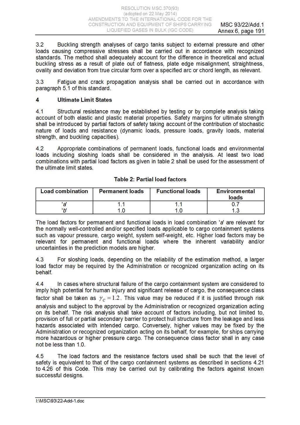
191
ANNEX 5. DRAFT RESOLUTION MSC.[ ](93) (adopted on [ ])
 (adopted on [ ])](/thumbs/90/102611796.jpg "ANNEX 5. DRAFT RESOLUTION MSC.[ ](93) (adopted on [ ])") Annex 5, page 1 ANNEX 5 DRAFT RESOLUTION MSC.[ ](93) (adopted on [ ]) ADOPTION OF AMENDMENTS TO THE INTERNATIONAL CODE FOR THE CONSTRUCTION AND EQUIPMENT OF SHIPS CARRYING DANGEROUS CHEMICALS IN BULK (IBC
Annex 5, page 1 ANNEX 5 DRAFT RESOLUTION MSC.[ ](93) (adopted on [ ]) ADOPTION OF AMENDMENTS TO THE INTERNATIONAL CODE FOR THE CONSTRUCTION AND EQUIPMENT OF SHIPS CARRYING DANGEROUS CHEMICALS IN BULK (IBC
RESOLUTION MSC.235(82) (adopted on 1 December 2006) ADOPTION OF THE GUIDELINES FOR THE DESIGN AND CONSTRUCTION OF OFFSHORE SUPPLY VESSELS, 2006
 (adopted on 1 December 2006) ADOPTION OF THE GUIDELINES FOR THE DESIGN AND CONSTRUCTION OF OFFSHORE SUPPLY VESSELS, 2006") MSC 82/24/Add.2 RESOLUTION MSC.235(82) CONSTRUCTION OF OFFSHORE SUPPLY VESSELS, 2006 THE MARITIME SAFETY COMMITTEE, RECALLING Article 28(b) of the Convention on the International Maritime Organization
MSC 82/24/Add.2 RESOLUTION MSC.235(82) CONSTRUCTION OF OFFSHORE SUPPLY VESSELS, 2006 THE MARITIME SAFETY COMMITTEE, RECALLING Article 28(b) of the Convention on the International Maritime Organization
ST. VINCENT AND THE GRENADINES
 ST. VINCENT AND THE GRENADINES MARITIME ADMINISTRATION CIRCULAR N SOL 036 Amendment to SOLAS 1974 as amended, Resolution MSC.256 (84) TO: SHIPOWNERS & SHIPS OPERATORS & MANAGERS, MASTERS SURVEYORS TO FLAG
ANNEX 2. RESOLUTION MSC.256(84) (adopted on 16 May 2008)
 (adopted on 16 May 2008)") RESOLUTION MSC.256(84) (adopted on 16 May 2008) ADOPTION OF AMENDMENTS TO THE INTERNATIONAL CONVENTION FOR THE SAFETY OF LIFE AT SEA, 1974, AS AMENDED THE MARITIME SAFETY COMMITTEE, RECALLING Article 28(b)
RESOLUTION MSC.256(84) (adopted on 16 May 2008) ADOPTION OF AMENDMENTS TO THE INTERNATIONAL CONVENTION FOR THE SAFETY OF LIFE AT SEA, 1974, AS AMENDED THE MARITIME SAFETY COMMITTEE, RECALLING Article 28(b)
RESOLUTION MSC.32(63) adopted on 23 May 1994 ADOPTION OF AMENDMENTS TO THE INTERNATIONAL CODE FOR THE CONSTRUCTION AND EQUIPMENT OF SHIPS CARRYING
 adopted on 23 May 1994 ADOPTION OF AMENDMENTS TO THE INTERNATIONAL CODE FOR THE CONSTRUCTION AND EQUIPMENT OF SHIPS CARRYING") THE MARITIME SAFETY COMMITTEE, RECAING Article 28(b) of the Convention on the International Maritime Organization concerning the functions of the Committee, RECAING ALSO resolution MSC.5(48), by which
THE MARITIME SAFETY COMMITTEE, RECAING Article 28(b) of the Convention on the International Maritime Organization concerning the functions of the Committee, RECAING ALSO resolution MSC.5(48), by which
RESOLUTION A.567(14) adopted on 20 November 1985 REGULATION FOR INERT GAS SYSTEMS ON CHEMICAL TANKERS
 adopted on 20 November 1985 REGULATION FOR INERT GAS SYSTEMS ON CHEMICAL TANKERS") INTERNATIONAL MARITIME ORGANIZATION A 14/Res.567 16 January 1986 Original: ENGLISH ASSEMBLY - 14th session Agenda item lo(b) IMO RESOLUTION A.567(14) adopted on 20 November 1985 THE ASSEMBLY, RECALLING
INTERNATIONAL MARITIME ORGANIZATION A 14/Res.567 16 January 1986 Original: ENGLISH ASSEMBLY - 14th session Agenda item lo(b) IMO RESOLUTION A.567(14) adopted on 20 November 1985 THE ASSEMBLY, RECALLING
Compiled by Nicholas H. Moore.
 CONTENTS 1 CODE FOR THE CONSTRUCTION AND EQUIPMENT OF SHIPS CARRYING LIQUEFIED GASES IN BULK Preamble CHAPTER I GENERAL 1.1 General 1.2 Application 1.3 Hazards 1.4 Definitions 1.5 Equivalents 1.6 Survey
RESOLUTION MSC.256(84) (adopted on 16 May 2008) ADOPTION OF AMENDMENTS TO THE INTERNATIONAL CONVENTION FOR THE SAFETY OF LIFE AT SEA, 1974, AS
 (adopted on 16 May 2008) ADOPTION OF AMENDMENTS TO THE INTERNATIONAL CONVENTION FOR THE SAFETY OF LIFE AT SEA, 1974, AS") RESOLUTION MSC.256(84) ADOPTION OF AMENDMENTS TO THE INTERNATIONAL CONVENTION FOR THE SAFETY OF LIFE AT SEA, 1974, AS AMENDED THE MARITIME SAFETY COMMITTEE, RECALLING Article 28(b) of the Convention on
RESOLUTION MSC.256(84) ADOPTION OF AMENDMENTS TO THE INTERNATIONAL CONVENTION FOR THE SAFETY OF LIFE AT SEA, 1974, AS AMENDED THE MARITIME SAFETY COMMITTEE, RECALLING Article 28(b) of the Convention on
ANNEX AMENDMENTS TO THE INTERNATIONAL CODE FOR FIRE SAFETY SYSTEMS (FSS CODE) CHAPTER 15 INERT GAS SYSTEMS
 CHAPTER 15 INERT GAS SYSTEMS") Annex 3, page 2 ANNEX AMENDMENTS TO THE INTERNATIONAL CODE FOR FIRE SAFETY SYSTEMS (FSS CODE) CHAPTER 15 INERT GAS SYSTEMS The text of existing chapter 15 is replaced by the following: "1 Application This
Annex 3, page 2 ANNEX AMENDMENTS TO THE INTERNATIONAL CODE FOR FIRE SAFETY SYSTEMS (FSS CODE) CHAPTER 15 INERT GAS SYSTEMS The text of existing chapter 15 is replaced by the following: "1 Application This
RESOLUTION MSC.365(93) (adopted on 22 May 2014) AMENDMENTS TO THE INTERNATIONAL CONVENTION FOR THE SAFETY OF LIFE AT SEA, 1974, AS AMENDED
 (adopted on 22 May 2014) AMENDMENTS TO THE INTERNATIONAL CONVENTION FOR THE SAFETY OF LIFE AT SEA, 1974, AS AMENDED") RESOLUTION MSC.365(93) THE MARITIME SAFETY COMMITTEE, RECALLING Article 28(b) of the Convention on the International Maritime Organization concerning the functions of the Committee, RECALLING ALSO article
RESOLUTION MSC.365(93) THE MARITIME SAFETY COMMITTEE, RECALLING Article 28(b) of the Convention on the International Maritime Organization concerning the functions of the Committee, RECALLING ALSO article
ANNEX 4 ALTERNATIVE TEXT FOR OPERATIONAL GUIDELINES FOR VERIFICATION OF DAMAGE STABILITY REQUIREMENTS FOR TANKERS
 Annex 4, page 1 ANNEX 4 ALTERNATIVE TEXT FOR OPERATIONAL GUIDELINES FOR VERIFICATION OF DAMAGE STABILITY REQUIREMENTS FOR TANKERS GUIDELINES FOR VERIFICATION OF DAMAGE STABILITY FOR TANKERS PART 2 OPERATIONAL
ANNEX 19 DRAFT ASSEMBLY RESOLUTION
 Annex 19, page 1 ANNEX 19 DRAFT ASSEMBLY RESOLUTION CODE FOR THE TRANSPORT AND HANDLING OF HAZARDOUS AND NOXIOUS LIQUID SUBSTANCES IN BULK ON OFFSHORE SUPPORT VESSELS (OSV CODE) THE ASSEMBLY, RECALLING
RESOLUTION MSC.397(95) (adopted on 11 June 2015) AMENDMENTS TO PART A OF THE SEAFARERS' TRAINING, CERTIFICATION AND WATCHKEEPING (STCW) CODE
 (adopted on 11 June 2015) AMENDMENTS TO PART A OF THE SEAFARERS' TRAINING, CERTIFICATION AND WATCHKEEPING (STCW) CODE") RESOLUTION MSC.397(95) (adopted on 11 June 2015) THE MARITIME SAFETY COMMITTEE, RECALLING Article 28(b) of the Convention on the International Maritime Organization concerning the functions of the Committee,
RESOLUTION MSC.397(95) (adopted on 11 June 2015) THE MARITIME SAFETY COMMITTEE, RECALLING Article 28(b) of the Convention on the International Maritime Organization concerning the functions of the Committee,
RESOLUTION MSC.236(82) (adopted on 1 December 2006) ADOPTION OF AMENDMENTS TO THE GUIDELINES FOR THE TRANSPORT AND HANDLING OF LIMITED AMOUNTS OF
 (adopted on 1 December 2006) ADOPTION OF AMENDMENTS TO THE GUIDELINES FOR THE TRANSPORT AND HANDLING OF LIMITED AMOUNTS OF") RESOLUTION MSC.236(82) (adopted on 1 December 2006) ADOPTION OF AMENDMENTS TO THE GUIDELINES FOR THE TRANSPORT AND HANDLING OF LIMITED AMOUNTS OF HAZARDOUS AND NOXIOUS LIQUID SUBSTANCES IN BULK THE MARITIME
RESOLUTION MSC.236(82) (adopted on 1 December 2006) ADOPTION OF AMENDMENTS TO THE GUIDELINES FOR THE TRANSPORT AND HANDLING OF LIMITED AMOUNTS OF HAZARDOUS AND NOXIOUS LIQUID SUBSTANCES IN BULK THE MARITIME
NEW IGC CODE AND IGF CODE
 NEW IGC CODE AND IGF CODE SAFETY ASPECTS Raffaele Piciocchi Gas Center - Greece SAFETY4SEAS - Athens 1 October 2014 Content NEW IGC CODE DRAFT IGF CODE 2 The New IGC Code A new IGC Code has been approved
MARINE CIRCULAR MC-25/2012/1
 Singapore Operations Office: 10 Anson Road #25-16, International Plaza, Singapore 079903 Tel: (65) 6224 2345 Fax: (65) 6227 2345 Email: info@tvship.com Website: www.tvship.com 4/2013 MARINE CIRCULAR MC-25/2012/1
Installation of Ballast Water Management Systems
 (Sept 2015) (Rev.1 May 2016) Installation of Ballast Water Management Systems 1. Application In addition to the requirements contained in BWM Convention (2004), the following requirements are applied to
ANNEX 15. RESOLUTION MEPC.158(55) Adopted on 13 October 2006
 Adopted on 13 October 2006") MEPC 55/23 RESOLUTION MEPC.158(55) THE MARINE ENVIRONMENT PROTECTION COMMITTEE, RECALLING Article 38(a) of the Convention on the International Maritime Organization concerning the functions of the Marine
MEPC 55/23 RESOLUTION MEPC.158(55) THE MARINE ENVIRONMENT PROTECTION COMMITTEE, RECALLING Article 38(a) of the Convention on the International Maritime Organization concerning the functions of the Marine
DEVELOPMENT OF A CODE FOR THE TRANSPORT AND HANDLING OF LIMITED AMOUNTS OF HAZARDOUS AND NOXIOUS LIQUID SUBSTANCES IN BULK ON OFFSHORE SUPPORT VESSELS
 E SUB-COMMITTEE ON BULK LIQUIDS AND GASES 17th session Agenda item 12 2 November 2012 ENGLISH ONLY DEVELOPMENT OF A CODE FOR THE TRANSPORT AND HANDLING OF LIMITED AMOUNTS OF HAZARDOUS AND NOXIOUS LIQUID
INTERNATIONAL ASSOCIATION OF CLASSIFICATION SOCIETIES. Interpretations of the. IGF Code
 INTERNATIONAL ASSOCIATION OF CLASSIFICATION SOCIETIES s of the IGF Code CONTENTS GF1 Test for gas fuel tank s high level alarm Rev.1 July 2017 GF2 Ship Steel Protection against Liquefied Gas Fuel (Part
REPORT OF THE MARITIME SAFETY COMMITTEE ON ITS NINETY-SEVENTH SESSION
 E MARITIME SAFETY COMMITTEE 97th session Agenda item 22 MSC 97/22/Add.1 6 December 2016 Original: ENGLISH REPORT OF THE MARITIME SAFETY COMMITTEE ON ITS NINETY-SEVENTH SESSION Attached are annexes 1 to
ANNEX 2 RESOLUTION MEPC.124(53) Adopted on 22 July 2005 GUIDELINES FOR BALLAST WATER EXCHANGE (G6) THE MARINE ENVIRONMENT PROTECTION COMMITTEE,
 Adopted on 22 July 2005 GUIDELINES FOR BALLAST WATER EXCHANGE (G6) THE MARINE ENVIRONMENT PROTECTION COMMITTEE,") Page 1 RESOLUTION MEPC.124(53) Adopted on 22 July 2005 GUIDELINES FOR BALLAST WATER EXCHANGE (G6) THE MARINE ENVIRONMENT PROTECTION COMMITTEE, RECALLING Article 38(a) of the Convention on the International
Page 1 RESOLUTION MEPC.124(53) Adopted on 22 July 2005 GUIDELINES FOR BALLAST WATER EXCHANGE (G6) THE MARINE ENVIRONMENT PROTECTION COMMITTEE, RECALLING Article 38(a) of the Convention on the International
PART 1 GENERAL REQUIREMENTS
 PART 1 GENERAL REQUIREMENTS SECTION SUBJECT 1.1 Standards 1.2 Compliance procedures and certification 1.3 Building premises 1.4 Testing of structures 1.5 Materials 1.6 Definitions of expressions GENERAL
Testing Procedures of Watertight Compartments
 (1996) (Rev.1 Feb 2001) (Rev.2 May 2001) (Rev.3 May 2010) (Rev.4 Aug 2012) Testing Procedures of Watertight Compartments.1 Application Revision 4 of this UR is to be complied with in respect of the testing
RULES PUBLICATION NO. 94/P SUBDIVISION AND DAMAGE STABILITY OF NEW OIL TANKERS, CHEMICAL TANKERS AND GAS CARRIERS January
 RULES PUBLICATION NO. 94/P SUBDIVISION AND DAMAGE STABILITY OF NEW OIL TANKERS, CHEMICAL TANKERS AND GAS CARRIERS 2016 January Publications P (Additional Rule Requirements) issued by Polski Rejestr Statków
Circular China Classification Society (2014) Circ.No.54 Total No.538 Dec.31,2014 ( Total 25 Pages )
 Circ.No.54 Total No.538 Dec.31,2014 ( Total 25 Pages )") C C S 通函 Circular China Classification Society (2014) Circ.No.54 Total No.538 Dec.31,2014 ( Total 25 Pages ) To relevant departments of the Headquarters, Shanghai Rules & Research Institute, plan approval
C C S 通函 Circular China Classification Society (2014) Circ.No.54 Total No.538 Dec.31,2014 ( Total 25 Pages ) To relevant departments of the Headquarters, Shanghai Rules & Research Institute, plan approval
Technical Information
 Subject Medical Oxygen Cylinder onboard Tuvalu flagged Ships To whom it may concern Technical Information No. TEC-1037 Date 31 July 2015 The Tuvalu Government has notified ClassNK of the special requirements
10 December 2010 GUIDANCE FOR WATERTIGHT DOORS ON PASSENGER SHIPS WHICH MAY BE OPENED DURING NAVIGATION
 E 4 ALBERT EMBANKMENT LONDON SE1 7SR Telephone: +44 (0)20 7735 7611 Fax: +44 (0)20 7587 3210 Ref. T4/3.01 MSC.1/Circ.1380 10 December 2010 GUIDANCE FOR WATERTIGHT DOORS ON PASSENGER SHIPS WHICH MAY BE
INTERNATIONAL REGULATIONS FOR THE SAFETY OF FISHING VESSELS
 INTERNATIONAL REGULATIONS FOR THE SAFETY OF FISHING VESSELS CONSOLIDATED TEXT OF THE REGULATIONS ANNEXED TO THE TORREMOLINOS PROTOCOL OF 1993 RELATING TO THE TORREMOLINOS INTERNATIONAL CONVENTION FOR THE
RULES FOR THE CONSTRUCTION AND CLASSIFICATION OF SHIPS IDENTIFIED BY THEIR MISSIONS CHAPTERS SCOPE
 PART II RULES FOR THE CONSTRUCTION AND CLASSIFICATION OF SHIPS IDENTIFIED BY THEIR MISSIONS TITLE 12 CONTAINER SHIPS SECTION 1 NAVAL ARCHITECTURE CHAPTERS A SCOPE B DOCUMENTS, REGULATIONS AND STANDARDS
RESOLUTION MSC.224(82) (adopted on 8 December 2006) ADOPTION OF AMENDMENTS TO THE CODE OF SAFETY FOR DYNAMICALLY SUPPORTED CRAFT, AS AMENDED
 (adopted on 8 December 2006) ADOPTION OF AMENDMENTS TO THE CODE OF SAFETY FOR DYNAMICALLY SUPPORTED CRAFT, AS AMENDED") MSC 82/24/Add.1 RESOLUTION MSC.224(82) THE MARITIME SAFETY COMMITTEE, RECALLING Article 28(b) of the Convention on the International Maritime Organization concerning the functions of the Committee, RECALLING
MSC 82/24/Add.1 RESOLUTION MSC.224(82) THE MARITIME SAFETY COMMITTEE, RECALLING Article 28(b) of the Convention on the International Maritime Organization concerning the functions of the Committee, RECALLING
Periodical surveys of cargo installations on ships carrying liquefied gases in bulk
 (June 1999) (Rev.1 Mar 2006) (Rev.2 May 2007) (Rev.3 Mar 2010) (Corr.1 Feb 2011) (Rev.4 Oct 2013) Periodical surveys of cargo installations on ships carrying liquefied gases in bulk 1 General 1.1 Scope
RESOLUTION MEPC.86(44) adopted on 13 March 2000 AMENDMENTS TO THE GUIDELINES FOR THE DEVELOPMENT OF SHIPBOARD OIL POLLUTION EMERGENCY PLANS
 adopted on 13 March 2000 AMENDMENTS TO THE GUIDELINES FOR THE DEVELOPMENT OF SHIPBOARD OIL POLLUTION EMERGENCY PLANS") MEPC 44/20 RESOLUTION MEPC.86(44) THE MARINE ENVIRONMENT PROTECTION COMMITTEE, RECALLING Article 38(a) of the Convention on the International Maritime Organization concerning the function of the Committee,
MEPC 44/20 RESOLUTION MEPC.86(44) THE MARINE ENVIRONMENT PROTECTION COMMITTEE, RECALLING Article 38(a) of the Convention on the International Maritime Organization concerning the function of the Committee,
SOLAS requirements for nonpassenger ships 300 or above but less than 500 gross tonnage
 SOLAS requirements for nonpassenger ships 300 or above but less than 500 gross tonnage Guidance for owners, masters and surveyors for ships undertaking international voyages SOLAS requirements applied
RULES PUBLICATION NO. 119/P
 RULES PUBLICATION NO. 119/P PERIODIC SURVEYS OF FUEL INSTALLATIONS ON SHIPS OTHER THAN LIQUEFIED GAS CARRIERS UTILIZING GAS OR OTHER LOW FLASH POINT FUELS 2019 January Publications P (Additional Rule Requirements)
The Merchant Shipping (Marine Pollution) Regulations 2004
 Regulations 2004") CAYMAN ISLANDS Supplement No.12 published with Gazette No. 2 dated 27 January, 2004 THE MERCHANT SHIPPING (MARINE POLLUTION) LAW 2001 THE MERCHANT SHIPPING (MARINE POLLUTION) REGULATIONS, 2004 1 of 36
CAYMAN ISLANDS Supplement No.12 published with Gazette No. 2 dated 27 January, 2004 THE MERCHANT SHIPPING (MARINE POLLUTION) LAW 2001 THE MERCHANT SHIPPING (MARINE POLLUTION) REGULATIONS, 2004 1 of 36
Periodic Survey of Fuel Installations on Ships other than Liquefied Gas Carriers utilizing gas or other low flash point fuels
 (Jan 2017) Periodic Survey of Fuel Installations on Ships other than Liquefied Gas Carriers utilizing gas or other low flash point fuels CONTENTS 1. Application 2. Special Survey 2.1 Schedule 2.2 Scope
Minimum standard of competence in advanced training for liquefied gas tanker cargo operations (STCW Reg V/1-2)
") Minimum standard of in advanced training for liquefied gas tanker cargo operations (STCW Reg V/1-2) Column 2 Knowledge, understanding and proficiency Design and characteristics of a liquefied gas tanker
Minimum standard of in advanced training for liquefied gas tanker cargo operations (STCW Reg V/1-2) Column 2 Knowledge, understanding and proficiency Design and characteristics of a liquefied gas tanker
RESOLUTION MEPC.64(36) adopted on 4 November 1994 GUIDELINES FOR APPROVAL OF ALTERNATIVE STRUCTURAL OR OPERATIONAL ARRANGEMENTS AS CALLED FOR IN
 adopted on 4 November 1994 GUIDELINES FOR APPROVAL OF ALTERNATIVE STRUCTURAL OR OPERATIONAL ARRANGEMENTS AS CALLED FOR IN") MEPC 36/22 THE MARINE ENVIRONMENT PROTECTION COMMITTEE, RECALLING Article 38(a) of the Convention of the International Maritime Organization concerning the function of the Committee, NOTING resolution
MEPC 36/22 THE MARINE ENVIRONMENT PROTECTION COMMITTEE, RECALLING Article 38(a) of the Convention of the International Maritime Organization concerning the function of the Committee, NOTING resolution
Resolution A.1120(30) Adopted on 6 December 2017 (Agenda item 9)
 Adopted on 6 December 2017 (Agenda item 9)") E ASSEMBLY 30th session Agenda item 9 A 30/Res.1120 18 December 2017 Original: ENGLISH Resolution A.1120(30) Adopted on 6 December 2017 (Agenda item 9) SURVEY GUIDELINES UNDER THE HARMONIZED SYSTEM OF
E ASSEMBLY 30th session Agenda item 9 A 30/Res.1120 18 December 2017 Original: ENGLISH Resolution A.1120(30) Adopted on 6 December 2017 (Agenda item 9) SURVEY GUIDELINES UNDER THE HARMONIZED SYSTEM OF
C C S Technical Information
 C C S Technical Information (2018) Technical Information No.32 Total No.358 May.28,2018 (Total 2 pages+annexes) To: Relevant departments of the Headquarters of CCS, the Society s surveyors, Plan Approval
F All types of inert gas systems are to comply with the following:
 (1974) (Rev.1 1983) (Rev.2 1987) (Rev.3 May 1998) (Corr. Sept 2001) (Rev.4 May 2004) (Rev.5 Nov 2005) (Rev.6 May 2012) (Rev.7 May 2015) Inert Gas Systems.1 General Requirements.1.1 All types of inert gas
Means of escape from crew spaces on fishing ships
 Means of escape from crew spaces on fishing ships May 2018 Maritime New Zealand Position Statement PS-02-18 This document is uncontrolled if printed. Please refer to the Maritime New Zealand website for
Testing Procedures of Watertight Compartments
 (1996) (Rev.1 Feb 2001) (Rev.2 May 2001) (Rev.3 May 2010) (Rev.4 Aug 2012) (Rev.5 Jan 2015) (Rev.6 Sept 2016) Testing Procedures of Watertight Compartments.1 Application Revision 6 of this UR is to be
RESOLUTION MEPC.288(71) (adopted on 7 July 2017) 2017 GUIDELINES FOR BALLAST WATER EXCHANGE (G6)
 (adopted on 7 July 2017) 2017 GUIDELINES FOR BALLAST WATER EXCHANGE (G6)") Annex 9, page 1 ANNEX 9 RESOLUTION MEPC.288(71) (adopted on 7 July 2017) THE MARINE ENVIRONMENT PROTECTION COMMITTEE, RECALLING Article 38(a) of the Convention on the International Maritime Organization
Annex 9, page 1 ANNEX 9 RESOLUTION MEPC.288(71) (adopted on 7 July 2017) THE MARINE ENVIRONMENT PROTECTION COMMITTEE, RECALLING Article 38(a) of the Convention on the International Maritime Organization
Doors in watertight bulkheads of cargo ships and passenger ships
 (June 2002) (Rev.1 Oct 2018) Doors in watertight bulkheads of cargo ships and passenger ships Application This unified interpretation pertains to doors 1 located in way of the internal watertight subdivision
Technical Information
 Subject Introduction to the Outcomes of MSC94 To whom it may concern Technical Information No. TEC-1024 Date 9 March 2015 A summary of the decisions taken at the ninety-fourth session of the Maritime Safety
Rules for Classification and Construction Additional Rules and Guidelines
 VI Rules for Classification and Construction Additional Rules and Guidelines 11 Other Operations and Systems 6 Guidelines for the Preparation of Damage Stability Calculations and Damage Control Documentation
UNIFIED INTERPRETATIONS OF THE IGC CODE (AS AMENDED BY RESOLUTION MSC.370(93))
)") E 4 ALBERT EMBANKMENT LONDON SE1 7SR Telephone: +44 (0)20 7735 7611 Fax: +44 (0)20 7587 3210 MSC.1/Circ.1559 28 November 2016 UNIFIED INTERPRETATIONS OF THE IGC CODE (AS AMENDED BY RESOLUTION MSC.370(93))
E 4 ALBERT EMBANKMENT LONDON SE1 7SR Telephone: +44 (0)20 7735 7611 Fax: +44 (0)20 7587 3210 MSC.1/Circ.1559 28 November 2016 UNIFIED INTERPRETATIONS OF THE IGC CODE (AS AMENDED BY RESOLUTION MSC.370(93))
GUIDELINES FOR SURVEY OF OIL FLOATING STORAGE VESSELS FIXED AT ANCHORAGE
 GUIDANCE NOTES GD03-2017 CHINA CLASSIFICATION SOCIETY GUIDELINES FOR SURVEY OF OIL FLOATING STORAGE VESSELS FIXED AT ANCHORAGE 2017 Effective from 1 March 2017 BEIJING Chapter 1 GENERAL 1.1 Application
CARRIAGE OF DIRECT REDUCED IRON (DRI) BY SEA CHANGES TO THE IMO CODE OF SAFE PRACTICE FOR SOLID BULK CARGO
 BY SEA CHANGES TO THE IMO CODE OF SAFE PRACTICE FOR SOLID BULK CARGO") The Shipowners Protection Limited St Clare House, 30-33 Minories London EC3N 1BP TO ALL MEMBERS March 2010 Managers of The Shipowners Protection Mutual Protection Limited and Indemnity St Clare House,
The Shipowners Protection Limited St Clare House, 30-33 Minories London EC3N 1BP TO ALL MEMBERS March 2010 Managers of The Shipowners Protection Mutual Protection Limited and Indemnity St Clare House,
THE REPUBLIC OF LIBERIA LIBERIA MARITIME AUTHORITY
 Office of Deputy Commissioner of Maritime Affairs THE REPUBLIC OF LIBERIA LIBERIA MARITIME AUTHORITY Marine Notice POL-010 Rev. 04/10 TO: SUBJECT: ALL SHIPOWNERS, OPERATORS, MASTERS AND OFFICERS OF MERCHANT
To: Relevant departments of CCS Headquarters, Plan approval centers, CCS surveyors, relevant shipyards, designers and shipping companies
 Form: RWPRR401-B CCS Circular China Classification Society (2012) Circ. No. 14 Total No.176 January 29, 2012 (Total pages: 1+5 ) To: Relevant departments of CCS Headquarters, Plan approval centers, CCS
South African Maritime Safety Authority Ref: SM6/5/2/1 /1
 South African Maritime Safety Authority Ref: SM6/5/2/1 /1 Date: 27 March 2014 Marine Notice 6 of 2014 Sail and Motor Yachts of over 25 GT but less than 100 GT used for Charter Purposes TO ALL PRINCIPAL
PASSENGER SHIP SAFETY. Preliminary recommendations arising from the Costa Concordia marine casualty investigation. Submitted by Italy SUMMARY
 E MARITIME SAFETY COMMITTEE 92nd session Agenda item 6 18 March 2013 Original: ENGLISH PASSENGER SHIP SAFETY Preliminary recommendations arising from the Costa Concordia marine casualty investigation Submitted
Rules for Classification and Construction Ship Technology
 I Rules for Classification and Construction Ship Technology 1 Seagoing Ships 9 Oil Recovery Vessels Edition 1993 The following Rules come into force on 1st September, 1993. The respective latest edition
Procedural Requirement for Confined Space Safe Entry
 (Apr 2013) (Rev.1 May 2014) Procedural Requirement for Confined Space Safe Entry Contents 1 Objective 2 Definitions 2.1 Confined Space 2.2 Confined Space Entry (CSE) 2.3 Competent Person 2.4 Responsible
APPENDIX 4 STANDARD FORMAT FOR THE PROCEDURES AND ARRANGEMENTS MANUAL
 Page 42 APPENDIX 4 STANDARD FORMAT FOR THE PROCEDURES AND ARRANGEMENTS MANUAL Note 1: Note 2: The format consists of a standardized introduction and index of the leading paragraphs to each section. This
MSC Guidelines for Engine Cooling Systems
 S. T. Brady, CDR, Chief, Engineering Division References: Contact Information: a. 46 CFR 56.60, 56.50-95 & 56.50-96 (Subchapter F) b. 46 CFR 77.03-1 (Subchapter H) c. 46 CFR 90.20 & 46 CFR 96.03 (Subchapter
FLAMMABLE GASES AND FLAMMABLE CRYOGENIC FLUIDS
 CHAPTER 35 FLAMMABLE GASES AND FLAMMABLE CRYOGENIC FLUIDS SECTION 3501 GENERAL 3501.1 Scope. The storage and use of flammable gases shall be in accordance with this chapter. Compressed gases shall also
ANNEX 2 RESOLUTION MSC.216(82) (adopted on 8 December 2006)
 (adopted on 8 December 2006)") RESOLUTION MSC.216(82) (adopted on 8 December 2006) ADOPTION OF AMENDMENTS TO THE INTERNATIONAL CONVENTION FOR THE SAFETY OF LIFE AT SEA, 1974, AS AMENDED THE MARITIME SAFETY COMMITTEE, RECALLING Article
RESOLUTION MSC.216(82) (adopted on 8 December 2006) ADOPTION OF AMENDMENTS TO THE INTERNATIONAL CONVENTION FOR THE SAFETY OF LIFE AT SEA, 1974, AS AMENDED THE MARITIME SAFETY COMMITTEE, RECALLING Article
Testing Procedures of Watertight Compartments
 (1996) (Rev.1 Feb 2001) (Rev.2 May 2001) (Rev.3 May 2010) (Rev.4 Aug 2012) (Rev.5 Jan 2015) Testing Procedures of Watertight Compartments.1 Application Revision 45 of this UR is to be complied with in
OIL IN NAVIGABLE WATERS REGULATIONS [L.N. 101 of 1968.] under sections 5 and 7. [22nd April, 1968] [Comrnencernent.]
![OIL IN NAVIGABLE WATERS REGULATIONS [L.N. 101 of 1968.] under sections 5 and 7. [22nd April, 1968] [Comrnencernent.]](/thumbs/80/81393535.jpg "OIL IN NAVIGABLE WATERS REGULATIONS [L.N. 101 of 1968.] under sections 5 and 7. [22nd April, 1968] [Comrnencernent.]") OIL IN NAVIGABLE WATERS REGULATIONS [L.N. 101 of 1968.] under sections 5 and 7 [Comrnencernent.] [22nd April, 1968] 1. Short title and interpretation (1) These Regulations may be cited as the Oil in Navigable
OIL IN NAVIGABLE WATERS REGULATIONS [L.N. 101 of 1968.] under sections 5 and 7 [Comrnencernent.] [22nd April, 1968] 1. Short title and interpretation (1) These Regulations may be cited as the Oil in Navigable
Interpretations of the IMCO code for the Construction and Equipment of Ships carrying Liquefied Gases in Bulk
 INTERNATIONAL ASSOCIATION OF CLASSIFICATION SOCIETIES Interpretations of the IMCO code for the Construction and Equipment of Ships carrying Liquefied Gases in Bulk IACS Int. 2008 Contents, Page 1 CONTENTS
PASSENGER SHIPS Guidelines for preparation of Hull Structural Surveys
 (Feb 2010) PASSENGER SHIPS Guidelines for preparation of Hull Structural Surveys Contents 1 Introduction 2 Preparations for Survey 2.1 General 2.2 Conditions for survey 2.3 Access to structures 2.4 Survey
GUIDELINES ON SAFETY MANAGEMENT SYSTEMS FOR HOT WORK AND ENTRY INTO ENCLOSED SPACES
 OIL COMPANIES INTERNATIONAL MARINE FORUM GUIDELINES ON SAFETY MANAGEMENT SYSTEMS FOR HOT WORK AND ENTRY INTO ENCLOSED SPACES The OCIMF mission is to be the foremost authority on the safe and environmentally
Resolution A.1023(26) Adopted on 2 December 2009 CODE FOR THE CONSTRUCTION AND EQUIPMENT OF MOBILE OFFSHORE DRILLING UNITS, 2009 (2009 MODU CODE)
 Adopted on 2 December 2009 CODE FOR THE CONSTRUCTION AND EQUIPMENT OF MOBILE OFFSHORE DRILLING UNITS, 2009 (2009 MODU CODE)") INTERNATIONAL MARITIME ORGANIZATION E ASSEMBLY 26th session Agenda item 10 A 26/Res.1023 18 January 2010 Original: ENGLISH Resolution A.1023(26) Adopted on 2 December 2009 (Agenda item 10) THE ASSEMBLY,
INTERNATIONAL MARITIME ORGANIZATION E ASSEMBLY 26th session Agenda item 10 A 26/Res.1023 18 January 2010 Original: ENGLISH Resolution A.1023(26) Adopted on 2 December 2009 (Agenda item 10) THE ASSEMBLY,
RESOLUTION MSC.97(73) (adopted on 5 December 2000) ADOPTION OF THE INTERNATIONAL CODE OF SAFETY FOR HIGH-SPEED CRAFT, 2000 (2000 HSC CODE)
 (adopted on 5 December 2000) ADOPTION OF THE INTERNATIONAL CODE OF SAFETY FOR HIGH-SPEED CRAFT, 2000 (2000 HSC CODE)") RESOLUTION MSC.97(73) ADOPTION OF THE INTERNATIONAL CODE OF SAFETY FOR HIGH-SPEED CRAFT, 2000 (2000 HSC CODE) THE MARITIME SAFETY COMMITTEE, RECALLING Article 28(b) of the Convention on the International
RESOLUTION MSC.97(73) ADOPTION OF THE INTERNATIONAL CODE OF SAFETY FOR HIGH-SPEED CRAFT, 2000 (2000 HSC CODE) THE MARITIME SAFETY COMMITTEE, RECALLING Article 28(b) of the Convention on the International
RULES FOR CLASSIFICATION Naval vessels. Part 1 Classification and surveys Chapter 5 Surveys for submarines. Edition January 2016 DNV GL AS
 RULES FOR CLASSIFICATION Naval vessels Edition January 2016 Part 1 Classification and surveys Chapter 5 The content of this service document is the subject of intellectual property rights reserved by ("DNV
IMO DEVELOPMENT OF EXPLANATORY NOTES FOR HARMONIZED SOLAS CHAPTER II-1
 INTERNATIONAL MARITIME ORGANIZATION E IMO SUB-COMMITTEE ON STABILITY AND LOAD LINES AND ON FISHING VESSELS SAFETY 51st session Agenda item 3 SLF 51/3/2 10 April 2008 Original: ENGLISH DEVELOPMENT OF EXPLANATORY
API MPMS Chapter 17.6 Guidelines for Determining the Fullness of Pipelines between Vessels and Shore Tanks
 API MPMS Chapter 17.6 Guidelines for Determining the Fullness of Pipelines between Vessels and Shore Tanks 1. Scope This document describes procedures for determining or confirming the fill condition of
GUIDELINES ON OPERATIONAL INFORMATION FOR MASTERS IN CASE OF FLOODING FOR PASSENGER SHIPS CONSTRUCTED BEFORE 1 JANUARY 2014 *
 E 4 ALBERT EMBANKMENT LONDON SE1 7SR Telephone: +44 (0)20 7735 7611 Fax: +44 (0)20 7587 3210 MSC.1/Circ.1589 24 May 2018 GUIDELINES ON OPERATIONAL INFORMATION FOR MASTERS IN CASE OF FLOODING FOR PASSENGER
RULES PUBLICATION NO. 86/P EXPLANATORY NOTES TO SOLAS CONVENTION AND DIRECTIVE 2003/25/EC STABILITY AND SUBDIVISION REQUIREMENTS
 RULES PUBLICATION NO. 86/P EXPLANATORY NOTES TO SOLAS CONVENTION AND DIRECTIVE 2003/25/EC STABILITY AND SUBDIVISION REQUIREMENTS 2011 Publications P (Additional Rule Requirements) issued by Polski Rejestr
MSC Guidelines for Review of Cargo and Miscellaneous Vessel Stability (Subchapter I)
") S. E. HEMANN, CDR, Chief, Hull Division Purpose The purpose of this Plan Review Guideline is to provide the submitter with general guidance and information for the preparation and submission of stability
S. E. HEMANN, CDR, Chief, Hull Division Purpose The purpose of this Plan Review Guideline is to provide the submitter with general guidance and information for the preparation and submission of stability
DEVELOPMENT OF INTERNATIONAL CODE OF SAFETY FOR SHIPS USING GASES OR OTHER LOW-FLASHPOINT FUELS (IGF CODE) Report of the working group
 Report of the working group") E SUB-COMMITTEE ON CARRIAGE OF CARGOES AND CONTAINERS 1st session Agenda item 4 CCC 1/WP.3 11 September 2014 Original: ENGLISH DISCLAIMER As at its date of issue, this document, in whole or in part, is
E SUB-COMMITTEE ON CARRIAGE OF CARGOES AND CONTAINERS 1st session Agenda item 4 CCC 1/WP.3 11 September 2014 Original: ENGLISH DISCLAIMER As at its date of issue, this document, in whole or in part, is
MSC/Circular.649 International Convention for the Safety of Life at Sea, 1974, as amended (Adopted on 8 June 1994)
") Sivu 1/8 Lloyd's Register Rulefinder 2016 - Version 9.25 MSC/Circular.649 International Convention for the Safety of Life at Sea, 1974, as amended (Adopted on 8 June 1994) MSC/Circular.649 International
Sivu 1/8 Lloyd's Register Rulefinder 2016 - Version 9.25 MSC/Circular.649 International Convention for the Safety of Life at Sea, 1974, as amended (Adopted on 8 June 1994) MSC/Circular.649 International
MSC Guidelines for Review of Stability for Towing Vessels (M)
") S. E. HEMANN, CDR, Chief, Hull Division References Contact Information a. 46 CFR Subchapter M, Part 144 b. 46 CFR Subchapter S, Parts 170, 173 c. Navigation and Vessel Circular No. 17-91, CH 1, Guidelines
S. E. HEMANN, CDR, Chief, Hull Division References Contact Information a. 46 CFR Subchapter M, Part 144 b. 46 CFR Subchapter S, Parts 170, 173 c. Navigation and Vessel Circular No. 17-91, CH 1, Guidelines
Transport of gas tanks for motor vehicles
 United Nations Secretariat ST/SG/AC.10/C.3/2016/51 Distr.: General 30 August 2016 Original: English Committee of Experts on the Transport of Dangerous Goods and on the Globally Harmonized System of Classification
1974 INTERNATIONAL CONVENTION FOR THE SAFETY OF LIFE AT SEA
 1974 INTERNATIONAL CONVENTION FOR THE SAFETY OF LIFE AT SEA Adopted in London, United Kingdom on 1 November 1974 ARTICLE I GENERAL OBLIGATIONS UNDER THE CONVENTION... 12 ARTICLE II APPLICATION... 12 ARTICLE
INTERNATIONAL MARITIME ORGANIZATION
 Page 1 of 16 INTERNATIONAL MARITIME ORGANIZATION IMO Resolution A.586(14) REVISED GUIDELINES AND SPECIFICATIONS FOR OIL DISCHARGE MONITORING AND CONTROL SYSTEMS FOR OIL TANKERS. ANNEX This document quote
Guidance for Ships Carrying CNG in Bulk
 2011 Guidance for Ships Carrying CNG in Bulk KOREAN REGISTER OF SHIPPING 2011 Guidance for Ships Carrying CNG in Bulk GC-05-E KOREAN REGISTER OF SHIPPING APPLICATION OF "GUIDANCE FOR SHIPS CARRYING CNG
MSC Guidelines for Review of Stability for Sailing Catamaran Small Passenger Vessels (T)
") K.B. FERRIE, CDR, Chief, Hull Division References: a. 46 CFR Subchapter T, Parts 178, 179 b. 46 CFR Subchapter S, Parts 170, 171 c. Marine Safety Manual (MSM), Vol. IV d. Navigation and Vessel Circular
K.B. FERRIE, CDR, Chief, Hull Division References: a. 46 CFR Subchapter T, Parts 178, 179 b. 46 CFR Subchapter S, Parts 170, 171 c. Marine Safety Manual (MSM), Vol. IV d. Navigation and Vessel Circular
SLOP RECEPTION AND PROCESSING FACILITIES
 RULES FOR CLASSIFICATION OF SHIPS NEWBUILDINGS SPECIAL SERVICE AND TYPE ADDITIONAL CLASS PART 5 CHAPTER 8 SLOP RECEPTION AND PROCESSING FACILITIES JANUARY 2011 CONTENTS PAGE Sec. 1 General Requirements...
properly applied assessment in the use.1 landmarks.1 approved in-service of ECDIS is not experience The primary method of fixing required for those
 STCW Code Table A-II/3 Specification of minimum standard of for officers in charge of a navigational watch and for masters on ships of less than 500 gross tonnage engaged on near-coastal voyages Ref: https://www.edumaritime.net/stcw-code
Government of Bermuda Department of Maritime Administration BERMUDA SHIPPING NOTICE
 Government of Bermuda Department of Maritime Administration 2015 027 BERMUDA SHIPPING NOTICE Maintenance and Inspection of Fixed Carbon Dioxide Fire Extinguishing Systems Ref: SOLAS 74/88 as amended, Regulation
IMO INTERIM GUIDELINES FOR WING-IN-GROUND (WIG) CRAFT
 CRAFT") INTERNATIONAL MARITIME ORGANIZATION 4 ALBERT EMBANKMENT LONDON SE1 7SR Telephone: 020 7735 7611 Fax: 020 7587 3210 Telex: 23588 IMOLDN G IMO E Ref. T4/3.01 MSC/Circ.1054 16 December 2002 INTERIM GUIDELINES
INTERNATIONAL MARITIME ORGANIZATION 4 ALBERT EMBANKMENT LONDON SE1 7SR Telephone: 020 7735 7611 Fax: 020 7587 3210 Telex: 23588 IMOLDN G IMO E Ref. T4/3.01 MSC/Circ.1054 16 December 2002 INTERIM GUIDELINES
GUIDELINES FOR VERIFICATION OF DAMAGE STABILITY REQUIREMENTS FOR TANKERS
 E 4 ALBERT EMBANKMENT LONDON SE1 7SR Telephone: +44 (0)20 7735 7611 Fax: +44 (0)20 7587 3210 GUIDELINES FOR VERIFICATION OF DAMAGE STABILITY REQUIREMENTS FOR TANKERS MSC.1/Circ.1461 8 July 2013 1 The Maritime
M-06 Nitrogen Generator (Nitrogen Making Machine)
") Guideline No.M-06 (201510) M-06 Nitrogen Generator (Nitrogen Making Machine) Issued date: 20 th October, 2015 China Classification Society Foreword This Guideline is a part of CCS Rules, which contains
Guideline No.M-06 (201510) M-06 Nitrogen Generator (Nitrogen Making Machine) Issued date: 20 th October, 2015 China Classification Society Foreword This Guideline is a part of CCS Rules, which contains
Chapter 7. Coal Cargoes. Properties and Characteristics 7.1
 Chapter 7 Coal Cargoes This chapter, and all of the chapters in Part 2, should be read in conjunction with the booklet Carrying Solid Bulk Cargoes Safely (Reference 16), published by Lloyd s Register/UK
MSC Guidelines for Tank Barge General Arrangements Procedure Number: C1-16 Revision Date: June 1, 2017
 T. O. PHILLIPS, CDR, Tank Vessel and Offshore Division Purpose: The purpose of this document is to provide guidance and information regarding the submission of General Arrangements plans for an Oceangoing
STEEL VESSELS 2008 RULES FOR BUILDING AND CLASSING PART 5C SPECIFIC VESSEL TYPES (CHAPTERS 7-10)
") Part 5C: Specific Vessel Types (Chapters 7-10) RULES FOR BUILDING AND CLASSING STEEL VESSELS 2008 PART 5C SPECIFIC VESSEL TYPES (CHAPTERS 7-10) American Bureau of Shipping Incorporated by Act of Legislature
Part 5C: Specific Vessel Types (Chapters 7-10) RULES FOR BUILDING AND CLASSING STEEL VESSELS 2008 PART 5C SPECIFIC VESSEL TYPES (CHAPTERS 7-10) American Bureau of Shipping Incorporated by Act of Legislature
LIQUEFIED GAS CARRIERS
 RULES FOR CLASSIFICATION OF SHIPS NEWBUILDINGS SPECIAL SERVICE AND TYPE ADDITIONAL CLASS PART 5 CHAPTER 5 LIQUEFIED GAS CARRIERS JANUARY 2008 This booklet includes the relevant amendments and corrections
Enhanced Discussion of Requirements for Commercial Fishing Vessels
 Update on U.S. Commercial Fishing Industry Vessel Requirements Based On Section 604 of the Coast Guard Authorization Act of 2010 (Public Law 111-281) And Section 305 of the Coast Guard and Maritime Transportation
AMENDMENTS TO SOLAS TO MANDATE ENCLOSED SPACE ENTRY AND RESCUE DRILLS
 E SUB-COMMITTEE ON DANGEROUS GOODS, SOLID CARGOES AND CONTAINERS 15th session Agenda item 17 DSC 15/17 6 July 2010 Original: ENGLISH AMENDMENTS TO SOLAS TO MANDATE ENCLOSED SPACE ENTRY AND RESCUE DRILLS
STCW Code Table A-V/1-1-1 Specification of minimum standard of competence in basic training for oil and chemical tanker cargo operations
 STCW Code Table A-V/1-1-1 Specification of minimum standard of in basic for oil and chemical tanker cargo operations Ref: https://www.edumaritime.net/stcw-code Source: IMO Contribute to Basic knowledge
Egress and means of escape from passenger spaces
 Egress and means of escape from passenger spaces May 2018 Maritime New Zealand Position Statement PS-01-18 This document is uncontrolled if printed. Please refer to the Maritime New Zealand website for
Liquefied gas cargo tanks and process pressure vessels
 .1 -.3 Liquefied gas cargo tanks and process pressure vessels.1 General.1.1 The present texts give the general principles which are applied by Classification Societies for approval and survey of the relevant
IMO INSPECTION AND SURVEY REQUIREMENTS FOR ACCOMMODATION LADDERS. Proposal for an amendment to SOLAS and associated guidelines
 INTERNATIONAL MARITIME ORGANIZATION E IMO SUB-COMMITTEE ON SHIP DESIGN AND EQUIPMENT 50th session Agenda item 5 DE 50/WP.8 7 March 2007 Original: ENGLISH INSPECTION AND SURVEY REQUIREMENTS FOR ACCOMMODATION
Commonwealth of Dominica. Office of the Maritime Administrator
 Commonwealth of Dominica Office of the Maritime Administrator TO: ALL SHIPOWNERS, OPERATORS, MASTERS, AND SEAFARERS OF MERCHANT SHIPS, AND RECOGNIZED ORGANIZATIONS SUBJECT: REFERENCE: EMERGENCY TRAINING