Lecture 8&9: Construction Dewatering
|
|
|
- Nickolas Carpenter
- 5 years ago
- Views:
Transcription

1 Arab Academy for Science, Technology & Maritime Transport Colleague of Engineering & Technology Construction & Building Engineering CB 523 Methods and Equipment for Construction 1 Lecture 8&9: Construction Dewatering Instructor: Dr. Ahmed Elyamany Courtesy of Dr. Ahmed Alhakeem & Dr. Ahmed Alhady
2 Overview Soil dewatering means the removal of water from the soil. Construction dewatering means Control of the subsurface and surface water environment in order to allow construction to proceed. Techniques for dealing with the problems that result depend on the excavation dimensions, soiltype, groundwater control requirements 2
3 Overview The simplest dewatering operations are carried out with little planning. Major operations in difficult conditions require advanced engineering and construction methods. (An aquifer is a permeable geological stratum or formation that can both store and transmit water in significant quantities). 3
4 Introduction Construction dewatering can become a costly issue if overlooked during project planning. In most contracts, dewatering is the responsibility of the contractor. The contractor selects the dewatering method and is responsible for its design and operation. The purpose of construction dewatering is to control the surface and subsurface hydrologic environment in suchawayastopermitthestructuretobeconstructed in the dry. 4
5 Introduction If ground water issues are addressed appropriately at the investigation and design stage, construction dewatering is rarely a problem. Construction dewatering has existed as a specialty industry for a long time. Consequently, a number of well-established techniques have been developed to lower the ground water table during excavation. The geology, ground water conditions, and type of excavation all influence the selection of dewatering technology. 5
6 Introduction The most common methods for dewatering include sumps, wells and wellpoints. Sumps provide localized, very shallow dewatering (less than 3 feet) and consist of pumping from perforated drums or casings in a gravel-filled backhoe pit. Sumps work best in tight, fine grained soils, or very coarse, bouldery deposits. 6
7 Introduction Wells are large-diameter (greater than 6 inches) holes, drilled relatively deep(greater than 10 feet), and contain slotted casings and downhole pumps. Wells work best in soils consisting of sand, or sand and gravel mixtures, and can dewater large areas to great depths. 7
8 Introduction Wellpoints are small-diameter (less than 6 inches), shallow wells, and are closely spaced (2 to 10 feet apart). effectively dewater coarse sands and gravels, or silts and clays. Theyhaveawiderangeofapplications. Use a vacuum system and their depth is limited to about 25 feet. systems generally cost more than either sumps or wells, and require near-continual maintenance. 8


9 Introduction Other dewatering techniques include: oground freezing, oelectroosmosis, overtical Sand Drains, owick Drains, ogrouting, etc. However, such techniques are very costly and used only for particularly difficult dewatering applications. 9
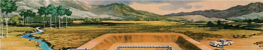
10 Underwater Excavations In special cases where the soil is very pervious or when it is not possible or desirable to lower the groundwater table, underwater excavations can be considered. If underwater excavation is to be performed, the work area must be enclosed with an impervious structure. Once the impervious structure is in place, the excavation is performed within the structure. Once the desired excavation level is achieved within the structure, it is sealed with an impervious layer, such as concrete, in order to prevent water from sipping into the work area. After the impervious seal has been constructed, the water remaining within the structure is pumped out and construction is completed. 10


11 Caissons Caisson is a structure that is constructed at location if the project site is on land, but if the project site is offshore, it is constructed on land and then floated to the site offshore. In the caisson method of construction, the excavation is performed from within the permanent structure. 11

12 Caissons 12
13 Caissons After the caisson is in position, excavation from within the caisson structure begins. As the excavation is carried out, the caisson structure starts to sinkbyitsownweight,orifnecessary,byimposedloads. This procedure continues until the desired foundation level is achieved. Figure 1 shows this process schematically. 13
14 Caissons 14
15 Caissons By injecting bentonite clay slurry at the soil-structure interface, adding weight, or in case of cohesive soils using jetting, the frictional resistance between the caisson and the surrounding ground may be significantly reduced. When a pile, or in this case caisson, must be driven through dense and hard materials, several driving aids have been developed. The principal function of these driving aids is to speed the driving operation and to prevent damage to the structure that results from heavy driving. 15
16 Caissons Jetting is applicable to those situations where structure must be driven through cohesive soil materials to greater depths. Water jets can be used to displace granular soils from beneaththetoeofapileorcaisson. Jetting is accomplished by pumping water through pipes attached to the side or center of the structure as it is driven. The flow of water creates a quick condition and thereby reduces skin friction along the sides of the driven structure. The result is that the structure drives more easily. 16
17 Caissons 17
18 Caissons During unwatering (pumping the water to outside of caisson) a caisson in cohesive soils, the upward flow from the surrounding groundwater induces a quick condition, which results in loss of strength at the bottom of excavation. In other words, if the flow is upward then the water pressure tends to lift the soil element. If the upward water pressure is high enough the effective stresses in the soil disappear, no frictional strength can be mobilizedandthesoilbehavesasafluid. This is the quick condition and is associated with piping instabilities around excavations. 18
19 Caissons Quick condition is shown in Figure 3 19
20 Caissons To prevent quick condition, the head difference causing flow, i.e. the difference between the groundwater table level and the standing water level within the caisson, should be kept low. Caissons should not be used in the case of existing structures that can be damaged due to loss of ground from beneath their foundations. At the desired excavation level, an impervious seal is placed, usually by using tremie concrete. Once the Tremie concrete seal is in place, the dewatering of the caisson can begin. 20

21 Caissons The tremie concrete placement method uses a vertical or near vertical pipe, through which concrete is placed by gravity feed below water level. 21
22 DewateringAnalysis What information is needed to properly select and design a dewatering program? 22

23 DewateringAnalysis Understand the objective of the dewatering program: Dimensions of excavation Adjacent structures Construction sequence 23
 Rock locations and formation Water chemistry(corrosivity) 24")
24 DewateringAnalysis SoilData Layering Soil Properties(permeability and density) Rock locations and formation Water chemistry(corrosivity) 24
25 DewateringAnalysis Hydrology Water quantities have two components: Storage: Water needed tobe removed to lowerground water to intended level(can be up to 2/3 of total pumping volume) (Impact on schedule!!!) Steady-state recharge Sequence and duration of work: Is uplift a consideration? Requirements for pressure relief as the structure is being built Must dewatering be relocated as construction proceeds? Must portions of the system be installed inside the excavation? How / Can we remove the dewatering system after construction? 25
26 Design of Dewatering Analysis Typically water needs to be pumped out of the soil through the useofvarioustypesofpumps 26
27 Design of Dewatering Analysis Un-confined Aquifer(Water Table Aquifer) Q: Quantity of water pumped K: Soil permeability H: Height of ground water table above impervious layer h: Height of reduced ground water table Ro: Radius of influence r:radiusofwell 27
28 Confined Aquifer Construction Dewatering Design of Dewatering Analysis 28
29 Design of Dewatering Analysis Soil Permeability Theabilityofwatertoflowthroughasoil 29
30 Design of Dewatering Analysis Self-Practice Example In a construction dewatering job in an unconfined aquifer of depth 20m you have installed a 30 m3/h pump. The radius of influence extends for 10m around the well. What is the expected drawdown? 30


31 Design of Dewatering Analysis Multi-layered Aquifers In the case where we have different soil layers that make up the aquifer we can calculate the effective permeability of the aquifer as follows: where K is the effective permeability; Ki is the permeability of layer i; Bi is the thickness of layer i; and B is the overall thickness of aquifer. 31
32 Design of Dewatering Analysis Multi-well Analysis Howcanwecalculatetheeffectofmultiplewells? If the drawdown in the aquifer is a small percentage (about 10 20%) of the aquifer thickness, the effect of each well can be superimposed on the other to determine the cumulative effect. Unconfined Aquifer Confined Aquifer M is the number of pump wells; H is the original water table level; K is the effective permeability; B is the layer thickness; Qj is the pumping rate of well j; Rj is the influence radius of well j; and rj is the distance between pumping well j and the 32

33 Design of Dewatering Analysis Self-Practice Example In the shown 20x50m excavation three dewatering wells are installed at an offset of 4m from the edge of the excavation. The depth of the excavation is 5m and the ground water table is 2m below the natural ground level. The ground water is in an unconfined aquifer of 25m depth 33
34 Design of Dewatering Analysis Site Pumping Tests In order to determine actual well performance, a site pumping test is commonly performed prior to the final design of the dewatering system. This will help determine the actual performance and soil permeability. Observation wells / peizometers are installed to monitor the actual drawdown 34


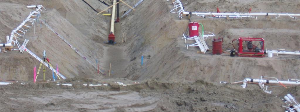
35 -Techniques Sumps, Ditches and Trenches A trench is excavated around the area to be dewatered. Surface pumps with hoses are used to pump water from the ditches. Practical to be used with relatively small quantities of water and small water heads. 35
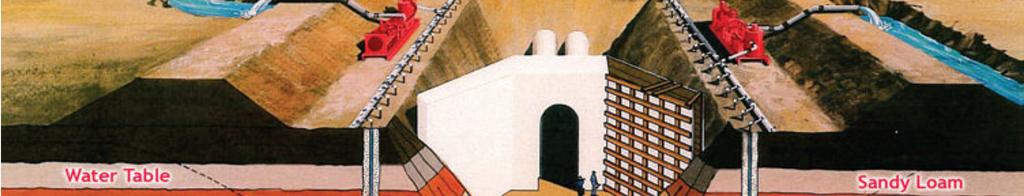
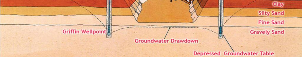
36 -Techniques Well point system Small pipes (up to 2.5 diameter) connected to screens at the bottom and a vacuum header pipe at the surface. Screens prevent soil particles from being pumped away with the water A centrifugal / vacum pump is connected to the manifold Wellpoint systems are constrained by the maximum possible suction head Common dewatering heights rangefrom m 36
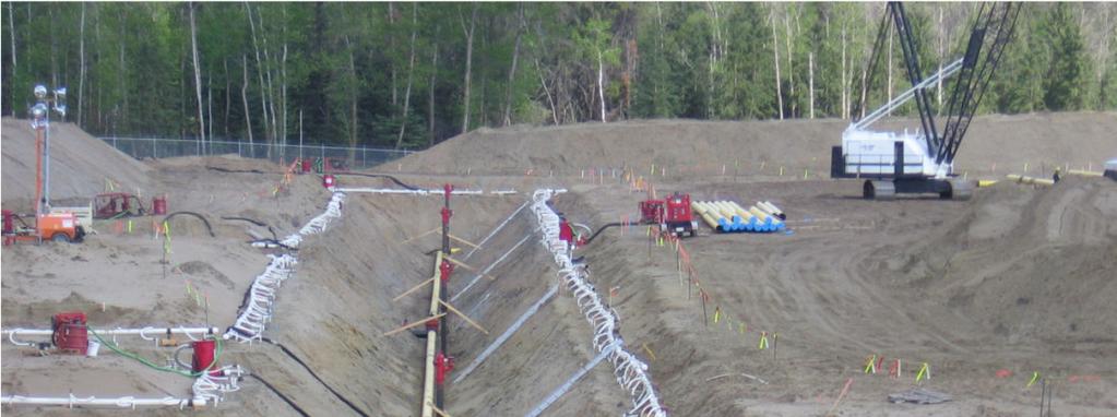
37 -Techniques Well point system Construction Steps 1. The wellpoints are jetted into the ground; 2. The annulars void is filled with filter media; 3. Thewellpointsareconnectedtoaheaderpipebymeansofariser; 4. Theheaderpipeisconnectedtosuctionpumpsforpumping 37
38 -Techniques Well point system 38
39 -Techniques Well point system Whatifweneedtolowerthegroundwatertablemore than the well point can handle? 2-stage well point system Deepwells 39
40 -Techniques Well point system 40
andtheamountofdrawdown that a well can achieve is limited only by thesizeofthepump.")
41 -Techniques Deep Well Consistsofaboreholefittedwithaslotted liner and an electric submersible pump. As the pump is submersible, there is no suction head limitation as for well points. Deep wells work best in soils with specific permeability profiles (k=1x10⁻⁵ cm/s to 1x10⁻⁷ cm/s)andtheamountofdrawdown that a well can achieve is limited only by thesizeofthepump. Pumps are engineered to withstand the aggressive corrosion factors associated withuseoversustainedperiodsoftimein a saline environment. 41

42 -Techniques DeepWell system 42
43 -Techniques DeepWell system Advantages: Ability to penetrate strata impervious to the jetting method of wellpoint systems. Installation of up to 100 feet deep or more in a single stage. Capable of pumping tens to thousands of gallons per minute per well. Deep Wells can be effective when placed outside of the jobsite work area. 43
44 -Techniques Ground Freezing Provides both a water cutoff and a structural cofferdam. Widely used in Europe. 44


45 -Techniques Ground Freezing Freeze pipe are installed along the line of the wall to be frozen every 1m. Pipe consists of an external casing and an internal pipe. A refrigerated brine solution is circulated through the system and the freeze pipes. At the freeze plant a heat exchanger transfers the heat to the ground. 45
46 -Techniques Ground Freezing Important Considerations: Natural ground water velocities. Prevent formation of wall. Presence of external heat source. (e.g. adjacent pipelines). Softclaywillcreepwhenfrozen. Ground movement. This technique requires continuous temperature monitoring. Not economic in hot climates. 46
47 Other considerations during dewatering Power supply: Provision of electricity source. Safe electrical wiring on site. Provision of backup power supply. Environmental considerations during dewatering: Disposal of water. Impact on ground water aquifers. Impact on surrounding structures. Conducting pumping tests to verify actual site performance 47
48 Thank You Questions? 48
Construction Dewatering
 Construction Dewatering Introduction The control of groundwater is one of the most common and complicated problems encountered on a construction site. Construction dewatering can become a costly issue
ATCE-II. Construction Dewatering. Advanced Topics in Civil Engineering Construction Dewatering. Professor Kamran M. Nemati Second Semester
 Construction Dewatering ecture 13 The purpose of construction dewatering is to control the surface and subsurface hydrologic environment in such a way as to permit the structure to be constructed in the
An Introduction to Deep Foundations
 An Introduction to Deep Foundations J. Paul Guyer, P.E., R.A. Paul Guyer is a registered mechanical engineer, civil engineer, fire protection engineer and architect with over 35 years experience in the
DIRECTIONAL DRILLING
 DIRECTIONAL DRILLING 1. General. Installation of pipelines through the levee embankment using directional drilling technology is prohibited. Installation of pipelines through a flood control project foundation
W I L D W E L L C O N T R O L FLUIDS
 FLUIDS Fluids Learning Objectives You will learn about different fluids that can be used in well control. You will become familiar with the characteristics and limitations of fluids. You will learn general
ITEM 400 STRUCTURAL EXCAVATION AND BACKFILL
 AFTER MARCH 1, 2012 ITEM 400 STRUCTURAL EXCAVATION AND BACKFILL 400.1 Description. This item shall govern for all excavation required for the construction of all structures, except pipe or box sewers for
3. Types of foundation
 Foundation Engineering CE 48. Types of foundation & foundation materials Contents Introduction Shallow Foundations Deep Foundations Introduction Why different types of? General types of Introduction Why
PUSH PIER SYSTEMS STABILITY. SECURITY. INTEGRITY. Push Pier Systems PN #MBPPT
 PUSH PIER SYSTEMS STABILITY. SECURITY. INTEGRITY. PN #MBPPT Push Pier Systems About Foundation Supportworks is a network of the most experienced and knowledgeable foundation repair and new construction
Item 404 Driving Piling
 Item Driving Piling 1. DESCRIPTION Drive piling. 2. EQUIPMENT 2.1. Driving Equipment. Use power hammers for driving piling with specified bearing resistance. Use power hammers that comply with Table 1.
Special Provision No. 903S01 November OPSS 903, December 1983, Construction Specification for Piling is deleted and replaced with the following:
 SUPPLY EQUIPMENT FOR DRIVING PILES - Item No. SUPPLY EQUIPMENT FOR INSTALLING CAISSON PILES - Item No. SUPPLY EQUIPMENT FOR INSTALLING DISPLACEMENT CAISSON PILES - Item No. SHEET PILES - Item No. H-PILES
W I L D W E L L C O N T R O L PRESSURE BASICS AND CONCEPTS
 PRESSURE BASICS AND CONCEPTS Pressure Basics and Concepts Learning Objectives You will be familiarized with the following basic pressure concepts: Defining pressure Hydrostatic pressure Pressure gradient
TYPES OF FOUNDATION. Superstructure. Substructure. Foundation
 TYPES OF FOUNDATION Introduction: The lowest artificially built part of a structure which transmits the load of the structure to the soil lying underneath is called foundation. The supporting part of a
Dry Hydrants. The installation of a non-pressurized pipe system into local water sources provides a ready means of supplying water to fire engines.
 Dry Hydrants What is a Dry Hydrant? A dry hydrant is a non-pressurized pipe system permanently installed in existing lakes, ponds and streams that provides a suction supply of water to a fire department
REPORT GEO-TECHNICAL INVESTIGATION FOR THE PROPOSED BLOCK-7 SUB-STATION SY NO-225, NEAR RAYACHERLU VILLAGE
 REPORT ON GEO-TECHNICAL INVESTIGATION FOR THE PROPOSED BLOCK-7 SUB-STATION SY NO-225, NEAR RAYACHERLU VILLAGE CLIENT: KARNATAKA SOLAR POWER DEVELOPMENT CORPORATION BANGALORE 0 GEO-TECHNICAL INVESTIGATION
REPORT GEO-TECHNICAL INVESTIGATION FOR THE PROPOSED BLOCK-1 SUB-STATION SY NO-44, NEAR KYATAGANACHERLU VILLAGE
 REPORT ON GEO-TECHNICAL INVESTIGATION FOR THE PROPOSED BLOCK-1 SUB-STATION SY NO-44, NEAR KYATAGANACHERLU VILLAGE CLIENT: KARNATAKA SOLAR POWER DEVELOPMENT CORPORATION BANGALORE 0 GEO-TECHNICAL INVESTIGATION
Design Data 22M. Flotation of Circular Concrete Pipe. w w I = w - x 1000 (3) (SG x 1000)
 (SG x 1000)") Design Data M Flotation of Circular Concrete Pipe There are several installation conditions where there is the possibility that concrete pipe may float even though the density of concrete is approximately.4
Design Data M Flotation of Circular Concrete Pipe There are several installation conditions where there is the possibility that concrete pipe may float even though the density of concrete is approximately.4
CHAPTER 5: VACUUM TEST WITH VERTICAL DRAINS
 CHAPTER 5: VACUUM TEST WITH VERTICAL DRAINS 5.1 Introduction Using surcharging as the sole soil consolidation mean can take a long time to reach the desired soil settlement. Soil consolidation using prefabricated
SPECIFICATION FOR CAISSON CONSTRUCTION
 SPECIFICATION FOR CAISSON CONSTRUCTION 1.0 METHOD OF EXCAVATION Caissons shall be hand-excavated, i.e. using of hand-held air tools. Full details of support measures and any dewatering and/or grouting
Septic Tank Buoyancy Control 101. David Lentz, P.E.
 Septic Tank Buoyancy Control 101 David Lentz, P.E. Archimedes Principle https://physics.weber.edu/carroll/archimedes/principle.htm Archimedes Principle: The buoyant force is equal to the weight of the
Division of Environmental Quality Wellhead Protection Section
 Division of Environmental Quality Wellhead Protection Section 1 10 CSR 23-3.110 Plugging of Wells Any well which is to be abandoned must be plugged in accordance with these rules. If a well has been determined
Chapter 10 SWIMMING POOLS
 4-10-1: COMPLIANCE REQUIRED: Chapter 10 SWIMMING POOLS It shall be unlawful to construct, maintain, install or enlarge any swimming pool in the City except in compliance with the provisions of this Chapter.
APPENDIX A1 - Drilling and completion work programme
 APPENDIX A1 - Drilling and completion work programme Information about the well and drilling To the extent possible, the international system of units (SI) should be adhered to, and the drilling programme
Department of Civil & Geological Engineering GEOE Engineering Geology
 Department of Civil & Geological Engineering GEOE 218.3 Engineering Geology Assignment #3, Head, Pore Pressure & Effective Stress Due 08 Oct, 2010 NOTE: Numbered subscripts indicate depth, in metres, below
Water Storage for Agriculture
 Water Storage for Agriculture Ted van der Gulik, P.Eng. Partnership for Water Sustainability in BC Water Storage Options Dam! usually constructed within a watercourse! must follow the dam safety regulation!
LAKOS Waterworks. PWC Series Sand Separators. Installation & Operation Manual LS-829 (10/12)
") LAKOS Waterworks PWC Series Sand Separators Installation & Operation Manual LS-829 (10/12) Table of Contents Separator Operation... 3 Individual Model Details.... 4 Flow vs. Pressure Loss Chart 4 Installation
LAKOS Waterworks PWC Series Sand Separators Installation & Operation Manual LS-829 (10/12) Table of Contents Separator Operation... 3 Individual Model Details.... 4 Flow vs. Pressure Loss Chart 4 Installation
TAO Safety Policy No. HS-5.1 Page 1 of 15 Revision No. 2 Revision Date: July 19, 2005
 TAO Safety Policy No. HS-5.1 Page 1 of 15 Revision No. 2 1.0 OVERVIEW This safety policy provides guidance for conducting trenching and excavation activities at project sites. Emphasis is placed on sloping
AUTOMATED MONITORING EQUIPMENT FOR ACIP AND DD PILES
 AUTOMATED MONITORING EQUIPMENT FOR ACIP AND DD PILES Presented by: W. Morgan NeSmith, P.E. Berkel & Company Contractors Inc. 770.941.5100 mnesmith@berkelapg.com ANNUAL KANSAS CITY SPECIALTY GEOTECHNICAL
RESISTANCE OF COMPACTED ASPHALT MIXTURE TO MOISTURE INDUCED DAMAGE (Kansas Test Method KT-56)
") 5.9.56 RESISTANCE OF COMPACTED ASPHALT MIXTURE TO MOISTURE INDUCED DAMAGE (Kansas Test Method ) 1. SCOPE This test covers preparation of specimens and measurement of the change of tensile strength resulting
5.9.56 RESISTANCE OF COMPACTED ASPHALT MIXTURE TO MOISTURE INDUCED DAMAGE (Kansas Test Method ) 1. SCOPE This test covers preparation of specimens and measurement of the change of tensile strength resulting
TACKLING JACK-UP RIG NO-GO LOCATIONS. Prakasha Kuppalli ABSTRACT
 TACKLING JACK-UP RIG NO-GO LOCATIONS Prakasha Kuppalli ABSTRACT Jack-up rigs are deployed for drilling and work-over (maintenance) of offshore oil and gas wells for producing hydrocarbons. Rigs drill through
CONE PENETRATION TESTS
 February 25, 2015 John Doe, P.E. Acme Engineering and Testing 1234 Test Avenue, Suite 204 Lake Wales, FL 33853 Re: Sample CPT Soundings Dear Mr. Doe, Direct Push Services, LLC (DPS) was retained by Acme
Perched Box Caisson Overview. January 2014
 Perched Box Caisson Overview January 2014 Why perched box caissons? Perched box caissons are used to construct the portion of the river piers that will support the steel arch spans Construction can occur
Inflatable Packer Single & Double. Single & Double Packer Dimension. Wireline Packer. Water Testing Packer (WTP) Packer
 Packer") Inflatable Packer Single & Double Single & Double Packer Dimension Wireline Packer Water Testing Packer (WTP) Packer Packer Working Pressure & Depth Chart Packer Water Hand Pump Packer Air Driven Pump
Inflatable Packer Single & Double Single & Double Packer Dimension Wireline Packer Water Testing Packer (WTP) Packer Packer Working Pressure & Depth Chart Packer Water Hand Pump Packer Air Driven Pump
GROUND IMPROVEMENT USING RAPID IMPACT COMPACTION
 13 th World Conference on Earthquake Engineering Vancouver, B.C., Canada August 1-, Paper No. 9 GROUND IMPROVEMENT USING RAPID IMPACT COMPACTION Henrik KRISTIANSEN 1, Michael DAVIES SUMMARY Geotechnical
1 Exam Prep NSF/ANSI Tabs and Highlights
 1 Exam Prep NSF/ANSI 50 2015 Tabs and Highlights These 1 Exam Prep Tabs are based on ANSI/NSF 50-2015, Equipment for Swimming Pools, Spas, Hot Tubs and Other Recreational Water Facilities. Each 1 Exam
TECHNICAL MEMORANDUM 002 EMORANNO. 001
 TECHNICAL MEMORANDUM 002 EMORANNO. 001 To: Jack Synder, P.E. EES Consulting From: Mort McMillen, P.E. Paul Larson, SE Date: October 13, 2010 Project: Cc: Taylor Bowen Subject: Technical Memorandum (TM)
Annex E Bridge Pier Protection Plan
 Annex E Bridge Pier Protection Plan Table E1 Bridge Types and Locations Table E2 Flow Conditions For River Sections Figure E1 Bridge Abutment Protection Figure E2 Bridge Pier Protection Figure E3 Central
OIL SUPPLY SYSTEMS ABOVE 45kW OUTPUT 4.1 Oil Supply
 OIL SUPPLY SYSTEMS ABOVE 45kW OUTPUT 4.1 Oil Supply 4.1.1 General The primary function of a system for handling fuel oil is to transfer oil from the storage tank to the oil burner at specified conditions
TECHNICAL BENEFITS OF CJS / RAISE HSP. Technical Advantages
 TECHNICAL BENEFITS OF CJS / RAISE HSP Technical Advantages The HSP is designed for low- to mid- volume applications at flow rates of 1 cubic meter to 30 c. m per day. The benefits are in the details. The
UNIT-I SOIL EXPLORATION
 SIDDHARTH GROUP OF INSTITUTIONS :: PUTTUR Siddharth Nagar, Narayanavanam Road 517583 QUESTION BANK (DESCRIPTIVE) Subject with Code : Geotechnical Engineering - II (16CE127) Year & Sem: III-B.Tech & II-Sem
Perforation Design for Well Stimulation. R. D. Barree Barree & Associates LLC
 Perforation Design for Well Stimulation R. D. Barree Barree & Associates LLC Typical Shaped Charge Primer charge Main explosive charge Case or container Detonating cord groove ¾ point of initiation Liner
Guidance on piling, heavy loads, excavations, tunnelling and dewatering
 Guidance on piling, heavy loads, excavations, tunnelling and dewatering thameswater.co.uk/developerservices Contents 1 Introduction... 3 2 Works That Can Impact Our Assets And Cause Damage... 3 3 What
TECHNICAL SPECIFICATIONS SECANT CAISSON WALL TECHNICAL SPECIFICATIONS. October 19, Nanaimo Colliery Dam Auxiliary Spillway, Nanaimo, BC
 SECANT CAISSON WALL TECHNICAL TECHNICAL Nanaimo Colliery Dam Auxiliary Spillway, Nanaimo, BC Submitted to: Toby Seward City of Nanaimo 455 Wallace Street Nanaimo, BC V9R 5J6 Report Number: Distribution:
OTC MS. Free Span Rectification by Pipeline Lowering (PL) Method N. I. Thusyanthan, K. Sivanesan & G. Murphy
 Method N. I. Thusyanthan, K. Sivanesan & G. Murphy") OTC-24699-MS Free Span Rectification by Pipeline Lowering (PL) Method N. I. Thusyanthan, K. Sivanesan & G. Murphy Copyright 2014, Offshore Technology Conference This paper was prepared for presentation
OTC-24699-MS Free Span Rectification by Pipeline Lowering (PL) Method N. I. Thusyanthan, K. Sivanesan & G. Murphy Copyright 2014, Offshore Technology Conference This paper was prepared for presentation
INADVERTENT RETURN PLAN FOR HORIZONTAL DIRECTIONAL DRILLING (HDD)
") INADVERTENT RETURN PLAN FOR HORIZONTAL DIRECTIONAL DRILLING (HDD) FACILITY OPERATOR: NextEra Energy Resources, LLC 700 Universe Boulevard Juno Beach, FL 33408 For Horizontal Directional Drilling Contents
INADVERTENT RETURN PLAN FOR HORIZONTAL DIRECTIONAL DRILLING (HDD) FACILITY OPERATOR: NextEra Energy Resources, LLC 700 Universe Boulevard Juno Beach, FL 33408 For Horizontal Directional Drilling Contents
Equipment Productivity
 Arab Academy for Science, Technology & Maritime Transport College of Engineering & Technology Construction & Building Engineering CB 524 Methods and Equipment for Construction 2 Equipment Productivity
Casing Design. Casing Design. By Dr. Khaled El-shreef
 Casing Design By Dr. Khaled El-shreef 1 Casing Design CONTENTS Function of Casing Casing Types & Tools Strength Properties Casing Specification Casing Design 2 1 RUNNING AND CEMENTING CASING Reasons for
22. Specialty Valves.
 22. Specialty Valves. a. Types of Specialty Valves. 1) Use of the following specialty valves is covered in this section: Altitude Valve, Pressure Reducing Valve, Pressure Relief Valve, Swing Check Valve,
Well PGE-6 Decommissioning Evaluation PG&E Topock Compressor Station
 TECHNICAL MEMORANDUM Well PGE-6 Decommissioning Evaluation PG&E Topock Compressor Station DATE: February 28, 2006 Introduction This technical memorandum presents an evaluation of inactive water supply
Siting and Installation Manual
 Siting and Installation Manual B-Series Advanced Wastewater Treatment Units Revolutionary Waste Treatment Advanced Wastewater Treatment Units (ATUs) that deliver an unsurpassed performance at an unbeatable
Swimming Pool Requirements
 Swimming Pool Requirements 1. Definitions: Approved Safety Pool Cover. Means a manually or power-operated safety pool cover that meets all of the performance standards of the American Society for Testing
APPENDIX M Groundwater Monitoring Well Decommissioning Specifications
 APPENDIX M Groundwater Monitoring Well Decommissioning Specifications CP-43:Groundwater Monitoring Well Decommissioning Policy New York State Department of Environmental Conservation DEC POLICY Issuing
ROCKDALE COUNTY NEW SWIMMING POOL PLAN REVIEW
 ROCKDALE COUNTY NEW SWIMMING POOL PLAN REVIEW Pool Name: Address: Contractor: Phone: Number of Pools Applied for: The following is a list of facility requirements for opening a public pool. Read each requirement
WATER TREATMENT SYSTEM OPERATION MANUAL
 WATER TREATMENT SYSTEM OPERATION MANUAL SYSTEM COMPONENTS A demonstration video of the system is available on our YouTube channel. You can view it by clicking on the following link. youtube.com/watch?v=mwlcfeliuzc
Chapter 8: Reservoir Mechanics
 PTRT 1472: Petroleum Data Management II Chapter 8: Reservoir Mechanics - Reservoir drives Types of Natural Gas Reservoir Fluids Natural gas is petroleum in a gaseous state, so it is always accompanied
Sample Project with EPB TBM according to DIN 4085
 1 General The aim of the document is to provide information about the required input parameters and the necessary steps for the calculation of a face support pressure. This calculation is carried out under
Suction anchor foundations for tension and taut leg floaters in deep waters. Tension Leg Platform. Taut Leg Platform. upper chain. risers.
 Case history: Soil investigation for offshore suction anchors anchor foundations for tension and taut leg floaters in deep waters Alternative anchors for floating structures pile Over last 5 - years anchoring
SOIL ANCHORS ETSAB/UPC J.Llorens - ETSAB/UPC PASSIVE ANCHORS - ANTECEDENTS
 SOIL ANCHORS ignasi.llorens@upc.edu ETSAB/UPC - 2013 PASSIVE ANCHORS - ANTECEDENTS Antecedents of passive anchors can be found in Nature. Roots feed plants and provide uplift resistance against the wind
SITE S7: EMBANKMENT FAILURE WEST OF MILLARVILLE
 LANDSLIDE RISK ASSESSMENT SOUTHERN REGION SITE S7: EMBANKMENT FAILURE WEST OF MILLARVILLE LEGAL LOCATION: LSD 4-3-21-4 W5M and 1-4-21-4 W5M REFERENCE LOCATION ALONG HIGHWAY The slide area is located between
GOM Diving Safety Work Group
 GOM Diving Safety Work Group COMMITTEE WORK GROUP Underwater Excavation with Hand Jetting July 14, 2015 DISCLAIMER This US GOM DSWG document is not meant to be all inclusive, and not every rule and regulation
Introduction. Geomembrane lining systems are used in a variety of different applications. Landfill Lining Landfill Capping Salt Piles Lagoons / Ponds
 Contents 1. Introduction/Overview 2. Traditional Methods of Anchoring Geomembrane Liners 3. What can go wrong? 4. Net Down 5. Theory and how Net Down works 6. Installation Details 7. Technical Information
Protectingpipelinesfor
 24 Protectingpipelinesfor Michael Paulin, Damien Humby and Joseph Cocker, INTECSEA Canada, and Glenn Lanan, INTECSEA Inc., describe the process of trenching for the protection of pipelines in ice environments.
Float Equipment TYPE 925/926
 Type 925 Float Collar Plunger Valve Float Equipment For less demanding well conditions, such as shallower depths or lower pressures, Top- Co offers economical float equipment certified to API RP 10F category
Understanding pressure and pressure
 CHAPTER 1 1-1 PRESSURE BASICS Remember to think downhole. The concepts provided in this section cover the foundations for good well control. Understanding pressure and pressure relationships is important
Evaluation of the function of Vertical drains.
 International Coastal Symposium ICS2007 Gold Coast Australia. C. Brøgger and P. Jakobsen SIC Skagen Innovation Center Skagen 9990 Denmark sic@shore.dk SIC Skagen Innovation Center Skagen 9990 Denmark sic@shore.dk
Prof. B V S Viswanadham, Department of Civil Engineering, IIT Bombay
 43 Module 3: Lecture - 5 on Compressibility and Consolidation Contents Stresses in soil from surface loads; Terzaghi s 1-D consolidation theory; Application in different boundary conditions; Ramp loading;
CENGRS GEOTECHNICA PVT. LTD. Job No Sheet No. 1
 CENGRS GEOTECHNICA PVT. LTD. Job No. 214030 Sheet No. 1 INTERIM REPORT ON GEOTECHNICAL INVESTIGATION FOR PROPOSED 66 KV GRID PLOT AT G-7, DWARKA, NEW DELHI. 1.0 INTRODUCTION 1.1 Project Description M/s.
Aeration of Dugouts or Ponds with Compressed Air
 Revised October 2008 Agdex 716 (B36) Aeration of Dugouts or Ponds with Compressed Air Dugout aeration improves water quality by maintaining dissolved oxygen levels. Of all the methods used for improving
Ocean Motion Notes. Chapter 13 & 14
 Ocean Motion Notes Chapter 13 & 14 What is a Wave? Wave: movement of energy through a body of water How are Waves Caused? Caused mostly by wind Wind blowing on the water transmits energy to the water Size
Desaturating sand deposit by air injection for reducing liquefaction potential
 Desaturating sand deposit by air injection for reducing liquefaction potential M. Ishihara, M. Okamura & T. Oshita Public Works Research Institute, Tsukuba City, Japan. ABSTRACT: It has been known that
Mr. Michael Malone CPS Energy 145 Navarro Street, Mail Drop San Antonio, Texas Project No
 October 17, 2016 Mr. Michael Malone CPS Energy 145 Navarro Street, Mail Drop 100406 San Antonio, Texas 78296 Project No. 0352436 Subject: Compilation of Construction History Calaveras Power Station San
Innovating Gas-Lift for Life of Well Artificial Lift Solution. The Unconventional Solution!
 Innovating Gas-Lift for Life of Well Artificial Lift Solution The Unconventional Solution! Glenn Wilde Optimum Production Technologies Inc. Revive Energy Corp. Unconventional Oil & Gas Resources Unconventional
icon i150 / i350 Installation / Operation Manual
 i150 Concentrator i350 Concentrator icon i150 / i350 Installation / Operation Manual www.iconcentrator.com What You Will Need to Install Your icon In order to install your icon you will have to consider
EMERGENCY CORE COOLING SYSTEM SIMPLIFICATION
 EMERGENCY CORE COOLING SYSTEM SIMPLIFICATION XA9846601 R.S. HART Sheridan Park Research Community, Atomic Energy of Canada Ltd, Mississauga, Ontario D.B. RHODES Chalk River Laboratories, Atomic Energy
UNDERWATER BRIDGE INSPECTION REPORT STRUCTURE NO CSAH 4 OVER THE BEAVER RIVER ST. LOUIS COUNTY
 UNDERWATER BRIDGE INSPECTION REPORT STRUCTURE NO. 7635 CSAH 4 OVER THE BEAVER RIVER ST. LOUIS COUNTY JUNE 18, 2012 PREPARED FOR THE MINNESOTA DEPARTMENT OF TRANSPORTATION BY COLLINS ENGINEERS, INC. JOB
Introduction of world construction methods and trends. Franz-Werner Gerressen, Head of Method Development, Tokyo,
 Introduction of world construction methods and trends Franz-Werner Gerressen, Head of Method Development, Tokyo, 2017-11-29 1 Introduction of world construction methods and trends Outline Single Pass Piling
Blue Points 1 ¼ WELL POINT INSTALLATION INSTRUCTIONS
 Blue Points 1 ¼ WELL POINT INSTALLATION INSTRUCTIONS This brochure is designed to provide step-by-step instructional assistance to the individual who wishes to install a shallow water well system for residential
CAISSONS SECTION Section CAISSONS. Part 1-GENERAL
 Section 02380-CAISSONS Part 1-GENERAL 1.01 RELATED DOCUMENTS A. Drawings and general provisions of Contract, including General and Supplementary Conditions and Division 1 Specification Sections, apply
Office Use Only Fee Paid
 WASHOE COUNTY HEALTH DISTRICT ENVIRONMENTAL HEALTH SERVICES DIVISION 1001 East Ninth Street PO Box 11130 Reno, Nevada 89520 Telephone (775) 328-2434 Fax (775) 328-6176 www.washoecounty.us/health APPLICATION
STRUCTURAL STABILITY ASSESSMENT
 STRUCTURAL STABILITY ASSESSMENT CFR 257.73(d) Fly Ash Reservoir II Cardinal Plant Brilliant, Ohio October, 2016 Prepared for: Cardinal Operating Company Cardinal Plant Brilliant, Ohio Prepared by: Geotechnical
Lecture Outline Chapter 15. Physics, 4 th Edition James S. Walker. Copyright 2010 Pearson Education, Inc.
 Lecture Outline Chapter 15 Physics, 4 th Edition James S. Walker Chapter 15 Fluids Density Units of Chapter 15 Pressure Static Equilibrium in Fluids: Pressure and Depth Archimedes Principle and Buoyancy
Vacutrans Instructions
 Vacutrans Instructions EMPIRE ABRASIVE EQUIPMENT COMPANY 2101West Cabot Blvd. Langhorne, Pa 19047 215-752-8800, FAX 215-752-9373 Web Site: www.empire-airblast.com ASSEMBLY DETAIL Your Vacutrans unit has
Attachment 6. HDD Feasibility Report
 May 2016 May 2016 May 2016 Page 1 of 21 The Pipeline Project TABLE OF CONTENTS 1 Introduction... 3 2 HDD Crossings... 3 3 Design Parameters... 3 4 Tributary to Simonette River Crossing... 4 4.1 Watercourse
RIGID RISERS FOR TANKER FPSOs
 RIGID RISERS FOR TANKER FPSOs Stephen A. Hatton 2H Offshore Engineering Ltd. SUMMARY Recent development work on the subject of dynamic rigid (steel pipe) risers demonstrates that their scope of application
Dri-Line Mk3 Monnier Compressed Air Drain Trap
 5044050/2 IM-P504-24 CH Issue 2 Dri-Line Mk3 Monnier Compressed Air Drain Trap Installation and Maintenance Instructions 1. Safety information 2. General product information 3. Installation and Operation
Consult with manufacturers concerning permeation of the pipe walls, jointing materials, valve seats, etc.
 Design Manual Chapter 4 - Water Mains 4C - Facility Design 4C-1 Facility Design A. General Water mains and appurtenances, including hydrants and valves, should be provided along all streets including connections
CONSTRUCTION SPECIFICATION FOR PILING
 ONTARIO PROVINCIAL STANDARD SPECIFICATION METRIC OPSS 903 DECEMBER 1983 CONSTRUCTION SPECIFICATION FOR PILING 903.01 SCOPE 903.02 REFERENCES 903.03 DEFINITIONS 903.04 Not Used 903.05 MATERIALS 903.05.01
CIVE 554/650. Geotechnical Engineering. Rock. Soil. Water. Site Investigation Techniques. CIVE Knight 1. 1/8/2006 CIVE Knight 1
 CIVE 554/650 Site Investigation Techniques 1/8/2006 CIVE 554 - Knight 1 Geotechnical Engineering Soil Rock Water 1/8/2006 CIVE 554 - Knight 2 CIVE 554 - Knight 1 Key Soil Engineering Properties Compressibility
SPEED SHORE MANUFACTURER S TABULATED DATA "MHS" MODELS. STEEL MANHOLE SHIELDS 4 Single Wall 4 Double Wall 4 Double Wall with Cut-Outs
 SPEED SHORE MANUFACTURER S TABULATED DATA "MHS" MODELS STEEL MANHOLE SHIELDS 4 Single Wall 4 Double Wall 4 Double Wall with Cut-Outs January 01, 2005 3330 S. SAM HOUSTON PKWY E. HOUSTON, TEXAS 77047 Tel:
ROTAMAT Rotary Drum Fine Screen Ro 2 / RPPS
 WASTE WATER Solutions ROTAMAT Rotary Drum Fine Screen Ro 2 / RPPS Reliable and well-proven inlet screen for municipal sewage treatment plants and industrial wastewater and process water screening with
HCMTCB MATERIALS SAMPLING & TESTING PERFORMANCE CHECKLIST
 HCMTCB MATERIALS SAMPLING & TESTING PERFORMANCE CHECKLIST Release Date: January 7, 2014 Sampling Coarse Aggregate PERFORMANCE CHECKLIST AASHTO T-2 Sampling of Aggregates Sampling From A Stockpile 1 When
Step 1. PLANNING FOR THE INSTALLATION TOOLS REQUIRED
 Installation Guide Fiji Step 1. PLANNING FOR THE INSTALLATION TOOLS REQUIRED In planning for the installation of a new Viking pool, there are many important considerations that must be evaluated in order
GWINNETT COUNTY SWIMMING POOL PLAN REVIEW CHECKLIST
 GWINNETT COUNTY SWIMMING POOL PLAN REVIEW CHECKLIST Pool Name: Address: Contractor: Phone: Number of Pools Applied for: GENERAL INFORMATION Plan review paid Pool Piping plan stamped by Design Professional.
(Revised February,2005) CULVERTS, BRIDGES, AND FORDS
 CULVERTS, BRIDGES, AND FORDS") GUIDE TO STREAM CROSSINGS (Revised February,2005) CULVERTS, BRIDGES, AND FORDS Culverts, bridges, and fords are all methods used to cross-streams. Culverts are the most common stream crossing structure.
GUIDE TO STREAM CROSSINGS (Revised February,2005) CULVERTS, BRIDGES, AND FORDS Culverts, bridges, and fords are all methods used to cross-streams. Culverts are the most common stream crossing structure.
Coal and Water Protection. PADEP: Well Plugging & Subsurface Activities Division Bureau of Oil and Gas Planning & Program Management
 Coal and Water Protection PADEP: Well Plugging & Subsurface Activities Division Bureau of Oil and Gas Planning & Program Management Review of Applicable Regulations & Laws Coal protective casing: A string
METHOD 2E - DETERMINATION OF LANDFILL GAS PRODUCTION FLOW RATE. NOTE: This method does not include all of the
 287 METHOD 2E - DETERMINATION OF LANDFILL GAS PRODUCTION FLOW RATE NOTE: This method does not include all of the specifications (e.g., equipment and supplies) and procedures (e.g., sampling and analytical)
Squeeze Cementing. Brett W. Williams Cementing Technical Advisor January 2016 Tulsa API Meeting
 Squeeze Cementing Brett W. Williams Cementing Technical Advisor January 2016 Tulsa API Meeting Definition Squeeze Cementing is the process of applying hydraulic pressure to force or squeeze a cement slurry
FP McCann Tunnels and Shafts 1
 FP M c Cann FP McCann Tunnels and Shafts 1 The McCann range of shaft and tunnel products have been developed to meet the requirements of the latest industry standards which include the British Tunnelling
Dec 6 3:08 PM. Density. Over the last two periods we discussed/observed the concept of density. What have we learned?
 Over the last two periods we discussed/observed the concept of density. What have we learned? is a ratio of mass to volume describes how much matter is packed into a space is a property of both solids
Texas Administrative Code
 TITLE 16 PART 1 CHAPTER 3 RULE 3.13 Texas Administrative Code ECONOMIC REGULATION RAILROAD COMMISSION OF TEXAS OIL AND GAS DIVISION Casing, Cementing, Drilling, Well Control, and Completion Requirements
Standard Test Method for Infiltration Rate of Soils in Field Using Double-Ring Infiltrometer 1
 This document is not an ASTM standard and is intended only to provide the user of an ASTM standard an indication of what changes have been made to the previous version. Because it may not be technically