Diaphragm Accumulators
|
|
|
- Kenneth Burns
- 5 years ago
- Views:
Transcription
1 Diaphragm Accumulators
2 HYDAC Diaphragm Accumulators Index Page 1. Description 3 Introduction 3 Construction 3 2. Applications 4 3. Technical Data 6 Operation 6 Technical Specifications 6 Temperature Effect 6 Formulas for Sizing Accumulators 7 Sizing Example 7 4. Installation Requirements 8 5. Model Code 9 6. Welded Type (non-repairable) Specifications Threaded Type (repairable) Specifications 11 2
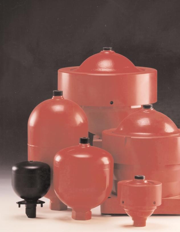
3 1. DESCRIPTION INTRODUCTION HYDAC diaphragm accumulators utilize the compressibility of a gas (nitrogen) in storing hydraulic energy. The gas is required because fluids are practically incompressible and thus, can not store energy by themselves. The diaphragm is utilized to separate the gas and the fluid sides of the accumulator The diaphragm accumulator functions by drawing in fluid from the hydraulic circuit when the pressure increases and thus, compresses the gas. It returns this energy to the circuit as the pressure decreases by the expansion of the gas. A poppet is incorporated into the diaphragm to prevent its extrusion through the fluid port. HYDAC manufactures two types of diaphragm accumulators: welded (non-repairable) threaded (repairable) These have been successfully applied to both industrial and mobile applications in energy storage, maintaining pressure, leakage compensation, and vehicle hydraulic systems (e.g. brake and suspension). CONSTRUCTION Welded Type gas valve accumulator shell diaphragm poppet fluid port It consists of: an electronic beam welded shell with gas charging valve or alternately, completely sealed. Fluid ports are available in various thread configurations. a flexible diaphragm to separate the gas and fluid sides. a poppet. Threaded Type gas valve accumulator shell locking ring diaphragm poppet fluid port It consists of: a forged upper section with the gas valve. a forged lower section with the fluid port. a locking ring to fasten the upper and lower sections together. a replaceable, flexible diaphragm to separate the gas and fluid sides. a poppet Diaphragm Materials Not all fluids are compatible with every elastomer at all temperatures. Therefore, HYDAC offers the following choice of elastomers: NBR (Standard Nitrile) LT-NBR (Low Temperature Nitrile) ECO (Epichlorohydrin) IIR (Butyl) FPM (Fluorelastomer) others available upon request. Corrosion Protection HYDAC offers internal and/or external protective coatings. If this is insufficient, stainless steel is also available. Mounting Position Diaphragm accumulators by design may be mounted in any position. In systems where contamination is a problem, we recommend a vertical mount with fluid port oriented downward. System Mounting HYDAC diaphragm accumulators are designed to be screwed directly onto the system. We also recommend the use of our mounting components, refer to Mounting Components brochure # A 3.502, to minimize risk of failure due to system vibrations. 3


4 2. APPLICATIONS HYDAC diaphragm accumulators have been applied successfully in the following industries: Agriculture Forestry Machine Tools Mining Mobile Equipment Off Road Equipment Some examples are shown here and on the next page. HYDAC welcomes the opportunity to work with you on your application. A diaphragm accumulator is used to support peak demand and for emergency supply in the event of a pump failure With hydraulic suspensions, diaphragm accumulators are used to absorb shock. Diaphragm accumulators can enhance motion control and dampen vibration. 4


5 This picture shows two energy storage applications on fatigue testing equipment. These pictures show a heavy duty shock application. 5
6 3. TECHNICAL DATA OPERATION Describing the operation of diaphragm accumulators: 1 The diaphragm is precharged with nitrogen. This causes the poppet to close, preventing the diaphragm from extruding out of the fluid port. 2 Accumulator at maximum working pressure. The difference in volume ( V) between the maximum and the minimum working pressure corresponds to the effective fluid volume: 3 When the minimum working pressure is reached, a small amount of fluid should remain in the accumulator. This is to prevent the poppet from impacting the base on each cycle. Thus, p 0 should always be lower than p 1. V = V1 - V2 TECHNICAL SPECIFICATION Maximum Working Pressure Please refer to tables on pages 10 and 11. In other countries maximum working pressure may be different. Maximum Allowable Pressure Ratio Ratio of max. working pressure (p 2 ) to gas precharge pressure ( p 0 ). welded type: size to 2 8 : 1 size 2.8 and : 1 threaded type all sizes 10 : 1 Nominal Volume (size) Please refer to tables on pages 10 and 11. Effective Gas Volume (V 0 ) Corresponds to the gas volume. Recommended Gas Precharge Pressure for energy storage: p 0 = 0.9 x p 1 p 1 = minimum working pressure for shock absorption: p 0 = (0.6 to 0.9) x p m p m = median working pressure at free flow for pulsation dampening: p 0 = (0.6 to 0.8) x p m p m = median working pressure TEMPERATURE EFFECT To ensure that the recommended precharged pressure is maintained, even at relatively low or high operating temperatures, the gas precharge pressure should be adjusted for temperature. The formulas below relate the precharge temperature (T 0 ) to the operating temperature (T). Please refer to the sizing example on page 7. V0 P2 V2 P1 V1 V Effective Fluid Volume Volume of fluid available between the working pressure p 2 and p 1. Fahrenheit p 0,T0 = p 0,T2 x ( T ) T p 0 = gas precharge pressure p 1 = minimum working pressure p 2 = maximum working pressure V 0 = effective gas volume of the accumulator V 1 = gas volume at p 1 Fluids Mineral oil, hydraulic oil, water, water-glycol, and water emulsions. For other fluids, please consult HYDAC. Operating Temperature Selection of the shell material and elastomer depends on the operating temperature range of the unit. For selection, please refer to pages 8 and 9. T 0 = precharge temperature in F T 2 = maximum operating temperature in F p 0,T 0 = gas precharge pressure at precharge temperature p 0,T 2 = gas precharge pressure at maximum operating pressure Celsius p 0,T0 = p 0,T2 x ( T ) T V 2 = gas volume at p 2 T 0 = temperature at precharging T 1 = minimum operating temperature T 2 = maximum operating temperature Flow Rate The maximum allowable flow rate depends on the accumulator size. For selection, please refer to pages 10 and 11. T 0 = precharge temperature in C T 2 = maximum operating temperature in C p 0,T 0 = gas precharge pressure at precharge temperature 6 p 0,T 2 = gas precharge pressure at maximum operating temperature
7 FORMULAS FOR SIZING ACCUMULATORS The compression and expansion processes taking place in hydropneumatic accumulator are governed by the general gas laws. The following applies for ideal gases: p 0 x V n 0 = p 1 x V n 1 = p 2 x V n 2, where the time related change of state is represented by the polytropic exponent n. For slow expansion and compression processes which occur almost isothermically, the polytropic exponent can be set at n=1. For rapid processes, the diabetic change of state can be calculated using n = k = 1.4 (for nitrogen as a diatomic gas) (1. For pressures above 3000 psi the real gas behavior deviates considerably from the ideal one, which reduces the effective fluid volume V. In such cases a correction is made which takes into account a change in the adiabatic exponent (k). By using the following formulas, the required gas volume V 0 can be calculated for various calculations. Pressures of up to 150 psi must always be used as absolute pressures in the formulas. Calculation Formulas V V0 polytropic: = isothermal: (n=1) adiabatic: (n = k = 1.4) V0 = P1 V0 = ( ) ( ) P1 V ( ) ( ) 1/n 1/n P2 P2 V ( ) ( ) P P2 Correction factors to take into account the real gas behavior (2 V 0,real = C i x V 0,ideal or V real = V ideal C i for adiabatic change of condition: V 0,real = C a x V 0,ideal or V real = V ideal C a 1 An estimate of the accumulator size and a selection of precharge pressure can be calculated similar to the sample shown. For more accurate sizing and design assistance, please contact HYDAC. 2 The correction factors can be taken from the graphs in the next column, depending on the pressure ratio p 2 /p 1 and the maximum working pressure p 2, which is given as a parameter, for an isothermal or adiabatic change of condition. correction factor Ci correction factor Ca Correction factor for isothermal change of condition max working pressure p2 = 0bar (5800psi) 300 bar (4350 psi) 200 bar (2900 psi) max working pressure p2 = 0bar (5800 psi) 300 bar (4350 psi) 200 bar (2900 psi) SIZING EXAMPLE pressure ratio p 2 /p 1 Correction factor for adiabatic change of condition pressure ratio p 2 /p 1 A brake cylinder has to be rapidly operated by means of an accumulator. The system must operate between 3000 psi and 1500 psi. The required fluid volume to operate properly is 15 in 3. The maximum operating temperature is 1 F while the minimum is 50 F. Given: max. working pressure p 2 = 3000 psi min. working pressure p 1 = 1500 psi effective fluid volume V = 15 in 3 max. operating temperature T 2 = 1 F min. operating temperature T 1 = 50 F Required: 1 necessary accumulator size, taking into account the real gas behavior 2 gas precharge pressure p 0 at 68 F (T 0 ) Solution: Since it is a rapid process, the change of condition of the gas can be assumed to be adiabatic. 1 Determination of gas precharge pressure p 0,T2 = 0.9 x p 1 = 0.9 x 1500 = 1350 psi. In order to maintain the minimum working pressure (p 1 ), one must calculate the precharge pressure at T 1. T p 0,T 1 = p 0,T 2 x ( T ) = 1350 x = 1148 psi 1150 psi Determination of the required gas volume: V 0, ideal = 1150 = = 46.5 in 3 ( ), (T1) P1 V ( ) ( ) , (T1) P2 15 ( ) ( ) Taking into account the real gas p 0 = 2 - Ca 1.16 p 1 behavior: V 0,real = C a x V 0, ideal = 53.9 in 3 Selected: Diaphragm accumulator SBO (60 in 3 ) b) Determination of the gas precharge pressure p 0 at 68 F: T0 + p 0,T 0 = p 0,T2 x ( T ) = 1350 x 68 + ( ) = 1188 psi Selected: Gas precharge pressure p 0,T psi 7
8 4. INSTALLATION REQUIREMENTS General Suggestions WARNING! Hydraulic accumulators are pressurized vessels and only qualified technicians should perform recommended repairs. Always drain the fluid completely from the accumulator before performing any work, such as recommended repairs (see Maintenance Instructions) or connecting pressure gauges. Never weld, braze, or perform any type of mechanical work on the accumulator shell. Precharge new or repaired accumulators with dry nitrogen to the proper gas precharge pressure (P 0 ). For more complete details, please refer to HYDAC s Operating and Installation Instructions. Country of Installation Pressure vessel codes vary depending upon the country of installation. In the United States and Canada pressure vessels are governed by ASME pressure vessel code. HYDAC manufactures according to these standards. For installation in countries outside of the United States, please consult HYDAC for the appropriate certifications*. The country of installation codes shown below are required for ordering: please refer to page 9.! CAUTION Elastomer Compatibility Table In order to maximize system performance it is important to match your system fluid and its temperature range with the appropriate elastomer compound. The table below illustrates the most common ones. For special requirements, please consult HYDAC. Operating Some Compound Temperature Typical Range Fluids NBR (BUNA N) 5 F to 180 F mineral oils 32 F to 180 F water and water-glycols LT-NBR (low temp. NBR) - F to 180 F mineral oils ECO (HYDRIN) -20 F to 0 F mineral oils IIR (BUTYL) -20 F to 200 F FPM (VITON) 5 F to 300 F Gas Charging Pressurized Vessel Use Dry Nitrogen Gas Only! phosphate esters brake fluids chlorinated hydrocarbons Notes: 1 The operating temperature range does vary with fluid types, please consult HYDAC for more specific fluid data. 2 The above typical fluids are some examples of the most common fluids, please consult HYDAC for specific data. 3 For other applications not listed, please consult HYDAC. 8 Argentina Australia Austria Brazil Canada Chile China Finland France Germany Great Britain (UK) Italy Japan Mexico Russia Sweden USA S F D K S/S1 S A9 L B A K M P E A6 R S * The European Community (EC) has the Pressure Equipment Directive (PED) that is being phased in. Contact HYDAC for details.
9 5. Model Code: Diaphragm Accumulators SBO E 4 / 112 S 210 CK 010 Series (see table) Size (see table) Configuration/Gas Port E1 = welded construction, rechargeable, HYDAC gas valve version 1 (M28 x 1.5) E2 = welded construction, factory precharged and sealed, non rechargeable (1 E4 = welded construction, rechargeable, HYDAC gas valve version 4 (8VI-ISO 4570) A6 = threaded construction, rechargeable, HYDAC gas valve version 1 (M28 x 1.5) Material Code Depending on application 112 = standard for oil service (mineral oil) Fluid Port 1 = carbon steel 3 = stainless steel (316) 4 = chemically plated carbon steel (water service) (2 6 = low temperature carbon steel (< -20 F) Shell 0 = synthetic coated carbon steel (water service) 1 = carbon steel 2 = chemically plated carbon steel (water service) (2 4 = stainless steel (316) 6 = low temperature carbon steel (< -20 F) Diaphragm Compound 2 = NBR (Buna N) 3 = ECO (Hydrin) 4 = IIR (Butyl) 5 = LT-BNR (low temperature Buna) 6 = FPM (Viton) 7 = others Country of Installation S = USA Others on request (refer to page 8) Maximum Working Pressure in bar (see table, for E2 design this may vary depending upon the gas precharge pressure) Connection Thread A = BSP (ISO 228) B = Metric (DIN 13) C = SAE (ANSI B 1.1) D = NPT (ANSI B 1.2) K = Hexagonal (3 CK = Standard SAE connection Gas Precharge Pressure (p 0 ) in bar (4 Not All Combinations Available Notes: 1) Up to size 1 2) Only wetted surfaces 3) For units with internal threads only 4) Only required for E2-model 9

10 6. WELDED TYPE (non-repairable) Series Max. Size Effective MAWP Wt. A ød (2 Thread F K (hex) Q p 2 :p 0 (liters) Gas Vol in 3 psi/bar lbs/kg in/mm in/mm SAE NPTF (3 in/mm gpm SBO 0 8 : SBO : SBO : SBO : SBO : SBO : SBO : SBO : SBO 1 8 : SBO : SBO : SBO : SBO : SBO : SBO : SBO 0 4 : SBO : / UNF 3/ /180 ( / UNF 3/ / /160 ( / /1 ( / /100 ( /16-12 UNF 3/ / /16-12 UNF 3/ /16-12 UNF 3/ /16-12 UNF 3/ /16-12 UNF 3/ /16-12 UNF 3/ ) Stainless steel version for chemical, water, and oil service 2) Diameter at electron beam weld may be up to larger 3) May be supplied with adapter
 øl M N Q p 2 :p 0 (liters) Gas Vol psi lbs in in in SAE in in in in gpm in 3 bar kg mm mm mm mm mm mm mm SBO 500 10 : 1 0.1 6 7200 4.2 4.33 1.18 3.74 3/4-16 1.26 2.68 0.87 1.")
11 7. THREADED TYPE (repairable) Series Max. Size Effective MAWP Wt. A B ød Thread F K (hex) øl M N Q p 2 :p 0 (liters) Gas Vol psi lbs in in in SAE in in in in gpm in 3 bar kg mm mm mm mm mm mm mm SBO : / SBO : /350 ( / / SBO : /600 ( / / SBO : /0 ( / / SBO : / SBO 0 10 : / SBO 0 10 : /180 ( / / ) Stainless steel version for chemical, water, and oil service 11


12 Other Products from HYDAC s Accumulator Line Bladder Accumulators The bladder style accumulator is a great general purpose accumulator. It has a wide range of sizes for energy storage requirements and is well suited for shock applications. Nominal volume 1 qt. to 15 gal. Max. working pressure 3000, 5000 and up to psi Flow rate up to 480 gpm Piston Accumulators A wide range of piston accumulators is available. Piston position monitoring is available using proximity switches, extending piston rod or ultrasonic techniques. Auxiliary gas bottles are frequently used with piston accumulators to provide the required gas volume. Nominal volume 1 qt. to 100 gal. Max. working pressure 3000, 5000, and up to psi Flow Rate up to 2000 gpm Request catalog # Request catalog # Mounting Components HYDAC mounting components are used to mount all types of hydropneumatic accumulators safely and simply, regardless of the mounting position. Our wide range includes suitable mounting components for every type of hydro pneumatic accumulator. Mounting components are used primarily for the following: to fix the accumulator into position, to carry the weight of the accumulator, and to counteract the forces exerted by the hydraulic lines. HYDAC also offers base brackets for larger accumulators for proper support and isolation from system vibrations. The brackets incorporate a rubber support ring for this reason. All mounting components can be easily bolted to your system. Request catalog # Charging & Gauging To maintain system performance, HYDAC recommends a regular check of the gas precharge pressure. A loss in the gas precharge pressure will cause a drop in the system efficiency and could cause damage to the bladder, diaphragm or piston accumulator. By means of a charging and gauging unit, hydro-pneumatics accumulators are precharged with dry nitrogen or their existing gas precharge pressure is checked. For these purposes, a charging and gauging unit is connected to a commercially available nitrogen bottle via a flexible hose. The charging and gauging units incorporate a gauge, check valve in the charging connection, manual bleed valve and T-handle. Request catalog # Copyright 2000 HYDAC TECHNOLOGY CORPORATION - Brochure - Diaphragm Accumulators # / HYDAC CORPORATION 2280 City Line Road Bethlehem, PA Phone (610) Fax (610) powerup@hydacusa.com
Diaphragm Accumulators
 1. DESCRIPTION 1.1. FUNCTION Fluids are practically incompressible and cannot therefore store pressure energy. The compressibility of a gas is utilised in hydro-pneumatic accumulators for storing fluids.
Diaphragm Accumulators
 Diaphragm Accumulators. DESCRIPTION.. FNCTION Fluids are practically incompressible and cannot therefore store pressure energy. The compressibility of a gas is utilised in HYDAC diaphragm accumulators
Hydraulic Accumulators with Back-Up Nitrogen Bottles
 Hydraulic Accumulators with Back-Up Nitrogen Bottles 1. GENERAL To complete the accumulator range, HYDAC provides a variety of useful accessory products. They guarantee correct installation and optimum
Bladder Accumulators High pressure
 Bladder Accumulators High pressure 1. DESCRIPTION 1.1. FUNCTION Fluids are practically incompressible and cannot therefore store pressure energy. The compressibility of a gas (nitrogen) is utilised in
Diaphragm Accumulators
 Diaphragm Accumulators. DESCRIPTION.. FNCTION Fluids are practically incompressible and cannot therefore store pressure energy. The compressibility of a gas is utilised in hydraulic accumulators for storing
HYDAC BLADDER ACCUMULATORS INDEX Page: 1. DESCRIPTION FUNCTION CONSTRUCTION MOUNTING POSITION TYPE OF MOUNTING 3 2. APPLIC
 Bladder Accumulators HYDAC BLADDER ACCUMULATORS INDEX Page: 1. DESCRIPTION 3 1.1. FUNCTION 3 1.2. CONSTRUCTION 3 1.3. MOUNTING POSITION 3 1.4. TYPE OF MOUNTING 3 2. APPLICATIONS 4 2.1. TYPICAL APPLICATIONS
Unit 24: Applications of Pneumatics and Hydraulics
 Unit 24: Applications of Pneumatics and Hydraulics Unit code: J/601/1496 QCF level: 4 Credit value: 15 OUTCOME 2 TUTORIAL 9 ACCUMULATORS The material needed for outcome 2 is very extensive so there are
Bladder Accumulators. General Information. Bladder Accumulators. Introduction. Accumulator Function. Why use a Bladder Accumulator?
 General Information Introduction Accumulator unction Bladder accumulators provide a means of regulating the performance of a hydraulic system. The design of the Stauff bladder accumulator makes use of
Bladder Accumulators Standard
 Bladder Accumulators 1. DESCRIPTION 1.1. FNCTION Fluids are practically incompressible and cannot therefore store pressure energy. The compressibility of a gas is utilised in hydraulic accumulators for
Application and Sizing
 Application and Sizing Energy accumulator: It is improbable that an hydraulic system use all of its capacity without interruptions. An hydropneumatic accumulator can store a certain amount of fluid that
FLUID POWER FLUID POWER EQUIPMENT TUTORIAL ACCUMULATORS. This work covers part of outcome 2 of the Edexcel standard module:
 FLUID POWER FLUID POWER EQUIPMENT TUTORIAL ACCUMULATORS This work covers part of outcome 2 of the Edexcel standard module: UNIT 21746P APPLIED PNEUMATICS AND HYDRAULICS The material needed for outcome
Bladder Accumulators Standard model
 Bladder Accumulators Standard model 1. DESCRIPTION 1.1. FUNCTION Fluids are practically incompressible and cannot therefore store pressure energy. The compressibility of a gas is utilised in hydraulic
How To Deal With Pre-Charge Loss In Bladder Accumulators Due To Gas Permeation
 How To Deal With Pre-Charge Loss In Bladder Accumulators Due To Gas Permeation By Ed Godin, Technical Services Manager, and Dave Broad, Chemist, Parker Hannifin Corporation, Hydraulic Accumulator Division
ACCUMULATOR OPERATING & MAINTENANCE INSTRUCTIONS
 ACCUMULATOR OPERATING & MAINTENANCE INSTRUCTIONS READ ALL INSTRUCTIONS PRIOR TO INSTALLATION AND OPERATION TO AVOID POSSIBLE INJURY Warning: Always consider any accumulator to contain pressure until proven
Accumulators Bladder Accumulators. Hydraulics. Technical Information Series CE + ASME. excellent pressure solutions
 Accumulators Bladder Accumulators Technical Information Series CE + ASME excellent pressure solutions Index Construction and Description General 3 Function 3 Overview of Roth bladder accumulators 4 Selection
Assembly-, installation- and maintenance instruction manual for bladder accumulators IBV / EBV , top reparable
 Page 1 von 8 Assembly-, installation- and maintenance instruction manual for bladder accumulators IBV / EBV 100-575, top reparable Content Seite 0 Legend 2 1 Overview 2 2 Accumulator assembly and installation
Hydraulic Piston Accumulators
 Hydraulic Installation All accumulators shipped from the factory will be pre-charged to a nominal pressure in order to seat the piston on the hydraulic cap. In this case the precharge will not be listed
HYDRAULIC & LUBE OIL UNIT EQUIPMENTS
 HYDRAULIC AND PROCESS TECHNOLOGY HYDRAULIC & LUBE OIL UNIT EQUIPMENTS Bladder Accumulators Rev.0 BLADDER ACCUMULATORS General operation procedure A) A flexible separator bladder is fitted into a pressure
PULSATION DAMPENER / SUPPRESSOR SERIES PDS PROVIDES MULTIPLE SYSTEM SAFEGUARDS
 PULSATION / SUPPRESSOR SERIES PDS PROVIDES MULTIPLE SYSTEM SAFEGUARDS FUNCTIONS: 1. Pulsation Dampener smooths pump flow 2. Surge Suppressor absorbs shocks and vibrations 3. Water Hammer Arrestor eliminates
Copyright, 2005 GPM Hydraulic Consulting, Inc.
 Troubleshooting and Preventive Maintenance of Hydraulic Systems Learning to Read the Signs of Future System Failures Instructed by: Al Smiley & Alan Dellinger Copyright, 2005 GPM Hydraulic Consulting,
Universal Charging and Testing Unit FPU-1
 1. DESCRIPTION 1.1. FUNCTION The charging and testing unit FPU-1 is used to charge accumulators with nitrogen or to check or to change the existing pre-charge pressure in accumulators. For this purpose
INDUSTRIAS IBAIONDO, HYDROPNEUMATIC TANKS
 IBAIONDO, HYDROPNEUMATIC TANKS IBAIONDO, INTRODUCTION Hydropneumatic tanks are designed to be used in potable water supply installations as a part of the pressure booster set in order to ensure the adequate
Accumulator selection
 3.1 Method of selection Many parameters are involved in the selection of an accumulator, the most important are: a) Minimum working pressure P1 and maximum pressure P2 The value of P2 must be lower or
hydro-pac, inc. Low-Pressure Gas Compressors 1500 to 6000 PSI
 hydro-pac, inc. LX-SERIES Low-Pressure Gas Compressors 1500 to 6000 PSI hydro-pac, inc. LX-SERIES Features Hydro-Pac LX-SERIES Gas Compressors feature: Oil-free non lubricated gas pistons and cylinders
Pressure reducing valve, pilot operated, Model 3DR
 RA 26 928/06.98 Pressure reducing valve, pilot operated, Model 3DR Nominal size 16 Series 5X Maximum operating pressure 3600 PSI (250 bar) Maximum flow 58.1 GPM (220 L/min) Contents Description Page Features
ACCU-PULSE Installation and Operation Instructions
 ACCU-PULSE Installation and Operation Instructions Pump Discharge Installation: Chargeable Models Step 1: Mounting Position Mount ACCU-PULSE as close to the pump discharge as possible to absorb the pulse
Power Valve: Precision Regulator. High precision, large capacity relief regulator
 Power Valve: Precision Regulator Series VEX High precision, large capacity relief regulator port large exhaust capacity pressure reducing valve which utilizes a nozzle flapper mechanism available as air
STAUFF. Accumulators & Accessories. Local Solutions for Individual Customers Worldwide
 STAUFF Accumulators & Accessories Local Solutions for Individual Customers Worldwide Contents Accumulators & Accessories Page Introduction 3 Material Options & Features 4, 5 Bladder Accumulators - STBA
Air Amplifiers & SYSTEMS
 Air Amplifiers & SYSTEMS We Accept VISA, MasterCard and American Express Air Amplifiers Point-of-Use Air Solutions Maximator air amplifiers are designed to boost plant air pressure or increase the supply
STAUFF Accumulators Accessories
 Local Solutions For Individual Customers Worldwide STUFF ccumulators Clamps & Supports 28 Safety Blocks 30 Burst Discs 34 Fuse Discs 35 Replacement Back-up Bottles 36 Clamps & Supports ccumulator Clamps
Booster Regulator/Air Tank
 Booster Regulator/Air Tank Increase factory air pressure by up to 4 times! Air-only operation requires no power supply, reduces heat generation, and Boost pressure allows easy installation. NEW Renewed
Cover headline. Cover subheadline. Check Valves
 Check Valves Cover headline Direct and pilot operated check valve functions for applications up to 5 bar (5 psi) and 7 L/min (6 USgpm) Cover subheadline EATON Screw-In Cartridge Valves E-VLSC-MC-E December
HIGH PRESSURE FILTERS DFDK Series Inline Duplex Filters 4568 psi up to 90 gpm
 DFDK Series Inline Duplex Filters 4568 psi up to 9 gpm Hydraulic Symbol DFDK QL L Ball Valve A DFDK QT T Ball Valve (sizes 33 or larger) A B B Features The DFDK Filters have a filter head of ductile iron
HYDROPNEUMATIC BLADDER ACCUMULATORS
 Documento1 03-11-2005 13:49 Pagina 1 HYDROPNEUMATIC BLADDER ACCUMULATORS EPE ITALIANA Srl INTERNATIONAL AUSTRALIA BELGIUM LUXEMBOURG BRAZIL CANADA EGYPT SLOVAKIA REPUBLIC HUNGARY CZECH REPUBLIC CHINA DENMARK
Safety and Shut-off Block SAF/DSV
 Safety and Shut-off Block SAF/DSV 1. DESCRIPTION 1.1. GENERAL The HYDAC safety and shut-off block is used to shut off and discharge hydraulic accumulators or consumers. It complies with the relevant safety
Safety and Shut-off Block SAF/DSV
 Safety and Shut-off Block SAF/DSV 1.1.1 Key to the circuit diagram Circuit diagram The HYDAC safety and shut-off block is used to shut off and discharge hydraulic accumulators or consumers. It complies
PRESSURE COMPENSATORS TECNORD
 PRESSURE COMPENSATORS 2-way, Compensating / Reducing Valves GPM PSI LPM BAR MODEL CAVITY PAGE 8 3500 30 245 DF-CP2 7/8 14 UNF 60 16 3500 60 245 QC-CP2 Special 62 Typical Schematic Typical application for
Related Products: Auto Drain Valve. Model/Specifications. Model
 Related Products: Auto Drain Valve /600 Drainage is automatically discharged in a reliable manner, without requiring human operators. Highly resistant to dust and corrosion, operates reliably, and a bowl
Desiccant Air Breathers DBE. Section 3: TNK SCHROEDER INDUSTRIES ACCESSORIES 21
 Desiccant Air Breathers DBE Section 3: SCHROEDER INDUSTRIES ACCESSORIES 21 Reservoir Accessories A hydraulic systems reservoir can play a significant role in the ingression of contamination into the system.
Piloted Non-Return Valves
 ed Non-Return Valves ed non-return valves are designed to protect installations: if the compressed air supply is removed, they lock the air supply to the cylinder, thus maintaining it in position. Product
Tank Blanketing Pressure Regulators RHPS Series
 www.swagelok.com Tank Blanketing Pressure Regulators RHPS Series Types: pressure reducing and vapor recovery 16L stainless steel construction 1/2, 1, and 2 in. end connections Working pressures up to 22
Check Valves. Pilot Operated Check Valves. Vickers. 4CG-10, 20 Series 4CS-03, 20 Series 4CT-06/10, 20 Series. Basic Characteristics.
 Vickers heck Valves Operated heck Valves 4G-10, 20 Series, 20 Series 4T-06/10, 20 Series Typical Section 4T1-06-D*-20-U, illustrating external drain and decompression features asic haracteristics Maximum
TECHNICAL DATA. Q = C v P S
 Page 1 of 13 1. DESCRIPTION The Viking 6 Model G-6000 Dry Valve Riser Assembly consists of a small profile, light weight, pilot operated valve that is used to separate the water supply from the dry sprinkler
Directional Valves. Hydraulic Operated Directional Valves
 Service Data Vickers Directional Valves Hydraulic Operated Directional Valves (F*) DG3V 8 (B) ** (L) (X) (*) (*) 10 (EN**) Released 04/96 5007.03/EN/0496/S DG3V-8-*(C) - (X) - 10 Spring Centered 473726
VERTICAL BLADDER TANK
 Balanced Pressure Proportioning System Reliable Foam System Requiring Only Water Power Perfect For Tight Spaces UL Listed, ASME, National Board Registered Bladder-UL162 Approved, High Tensile Pressure
HPB25 Hydraulic Paving Breaker
 INSTRUCTION MANUAL HPB25 Hydraulic Paving Breaker Read and understand all of the instructions and safety information in this manual before operating or servicing this tool. Register this product at www.greenlee.com
TECHNICAL DATA 3 MODEL G-3000 DRY VALVE RISER ASSEMBLY
 Page 1 of 13 1. DESCRIPTION The Viking 3 Model G-3000 Dry Valve Riser Assembly is equipped with a small profile, light weight, pilot operated valve that is used to separate the water supply from the dry
Leak free Pipe Rupture Valve for Excavators
 Leak free Pipe Rupture Valve for xcavators Series motion and progress Reference: 3 P 9575 1/11.6 Classification: 43.325.355...325.35 1/17 Contents Page 1 General description................................................................
HORIZONTAL BLADDER TANK
 Balanced Pressure Proportioning System Reliable Foam System Requiring Only Water Power Perfect For Low Ceilings UL Listed, ASME, National Board Registered Bladder-UL162 Approved, High Tensile Pressure
Serie 06-M6. Swing wafer check valve. made in. Application fields. Check valves E U R O P E WATER CONDITIONING INDUSTRY
 Swing wafer check valve BRANDONI made in E U R O P E Application fields WATER CONDITIONING INDUSTRY HEATING 38 www.brandoni.it The valves in series 06 are swing wafer check valves, manufactured in accordance
Safety and Shut-off Block SAF/DSV
 1. DESCRIPTION 1.1. GENERAL The HYDAC safety and shut-off block is used to shut off and discharge hydraulic accumulators or user units. It complies with the relevant safety standards in accordance with
BLADDER ACCUMULATORS LOW PRESSUR LIQUID SEPARATOR type ASBL
 BLADDER ACCUMULATORS LOW PRESSUR LIQUID SEPARATOR type ASBL 3.4 3.4.1 TECHNICAL DATA MAX OPERATING PRESSURE (PS): 60 bar PRESSURE TEST (PT): 1.43 x PS NOMINAL CAPACITIES: ASBL: 0.7-1 - 1.5-3 - 5 10 15
Test pumps. Pressure sources. Good reasons for proper and reliable calibration
 Test pumps Pressure is one of the most commonly measured quantities in engineering, which is why exact and reliable pressure measurement is especially important. However, the characteristics of the even
Pressure Sensing Valve - Model 4023
 Pressure Sensing Valve - Model 4023 Overview AMOT Model 4023 can be used as a 2 or 3-way capacity, pressure sensing valve. This valve is ideal for applications that require compressor suction and discharge
Full Range Pressure Compensating Variable Flow Control
 Engineering & Manufacturing Solutions Specifications: See flow chart for capacity. Rated for 3000 psi (207 bar). Weighs 7- ¾ lbs. (3.52 kg). 30-Micron Filtration Recommended. Torque to turn side lever
SDM to 8 sections monoblock valve D1WWDA02A
 SDM 1 SDM1 1 to 8 sections monoblock valve D1WWDA2A SDM1 Additional information This folder shows the product in the most standard configurations. Please contact Sales Dpt. for more detailed information
Components for air preparation and pressure adjustment. OUT port position ( ) connected Rear side. of IN port. Air tank. directly.
 connected Rear side. of IN port. Air tank. directly.") Components preparation and pressure adjustment ABP Overview ABP is a component that enables boosting by s only up to twice primary pressure (.0MPa max.) in combination with using air tank but not using
Components preparation and pressure adjustment ABP Overview ABP is a component that enables boosting by s only up to twice primary pressure (.0MPa max.) in combination with using air tank but not using
SATURNSERIES INTERCHANGE > ISO (for the couplings)
") Saturn Block INTERCHANGE > ISO 16028 (for the couplings) PATENTED ISO 16028 TECHNICAL FEATURES AND OPTIONS Interchange ISO 16028 (for the couplings) Sealing description Nitrile NBR Connection system Push
Saturn Block INTERCHANGE > ISO 16028 (for the couplings) PATENTED ISO 16028 TECHNICAL FEATURES AND OPTIONS Interchange ISO 16028 (for the couplings) Sealing description Nitrile NBR Connection system Push
Ball valve HKSF-W100. Ball valve HKSF-W100. RMA Kehl GmbH & Co. KG Oststrasse 17 D Kehl / Germany
 Ball valve HKSF-W100 RMA Kehl GmbH & Co. KG Oststrasse 17 D-77694 Kehl / Germany info@rma-kehl.de www.rma-armaturen.de 1 Design Features: RMA-ball valves type HKSF-W are fully welded and completely maintenance-free
TECHNICAL DATA Q = C. v P S. 2 Model G-2000 Dry valve. Page 1 of 13
 Page 1 of 13 1. Description The Viking 2 Model G-2000 Dry Valve Riser Assembly consists of a small profile, light weight, pilot operated valve that is used to separate the water supply from the dry sprinkler
P2* MODULAR SUBPLATES FOR ISO (CETOP 03) VALVES
 VALVES") 52 000/110 ED This series of modular subplates has been designed to make hydraulic circuits and can be used directly on power packs or on any other section of the machine. The subplates are assembled by
52 000/110 ED This series of modular subplates has been designed to make hydraulic circuits and can be used directly on power packs or on any other section of the machine. The subplates are assembled by
Compressors. Basic Classification and design overview
 Compressors Basic Classification and design overview What are compressors? Compressors are mechanical devices that compresses gases. It is widely used in industries and has various applications How they
SIMPLAIR PIPING TOOL. JXT Company
 SIMPLAIR PIPING INGERSOLL-RAND SIMPLAIR PIPING With push-in fittings and lightweight anodized aluminum pipe, a SimplAir system provides ideal connection throughout your entire air distribution system.
Bladder-Type Accumulators
 18 ladder-type ccumulators n Overview The typical bladder accumulator makes use of the considerable differences in the relative compressibility between a gas and a fluid. typical design consists of a gas
Pressure reducing valve, direct operated
 Electric Drives and Controls Table of contents Hydraulics Pressure reducing valve, direct operated Model ZDR 6 D Nominal size 6 Series 4X Maximum operating pressure 20 bar (3050 PSI) Maximum flow 50 L/min
FIK In-Tank Filters FIK. Max Flow: 170 gpm (643 lpm) Working Pressures to: Rated Static Burst to: Flow Range to:
 Working Pressures to: Rated Static Burst to: Flow Range to:") LOW PRESSURE FILTERS Max Flow: gpm ( lpm) In-Tank Filters Working Pressures to: Rated Static Burst to: psi kpa bar psi kpa bar Flow Range to: gpm lpm Features STYLE C STYLE D STYLE E in-tank filters are
LOW PRESSURE FILTERS Max Flow: gpm ( lpm) In-Tank Filters Working Pressures to: Rated Static Burst to: psi kpa bar psi kpa bar Flow Range to: gpm lpm Features STYLE C STYLE D STYLE E in-tank filters are
// ADapters GUIDelines
 // ADapters GUIDelines ADAPTER SELECTION Selection of an appropriate ALFAGOMMA adapter for a given application depends on the fluid system operating parameters listed below and the tube material and wall
Load Controls Screw In Cartridge Valves Pressures to 350 bar (5000 psi) Flows to 190 l/min (50 USgpm)
 Flows to 190 l/min (50 USgpm)") Vickers Cartridge Valves Load Controls Screw In Cartridge Valves Pressures to 50 bar (5000 psi) Flows to 90 l/min (50 USgpm) Rev. 2/99 722 Contents MODEL DESCRIPTION TYP. APPLICATION PRESSURE bar (psi)
Vickers Cartridge Valves Load Controls Screw In Cartridge Valves Pressures to 50 bar (5000 psi) Flows to 90 l/min (50 USgpm) Rev. 2/99 722 Contents MODEL DESCRIPTION TYP. APPLICATION PRESSURE bar (psi)
E 094 E 103 E 143 Tank top mounting Connection up to G1 / -16 SAE Nominal flow rate up to 135 l/min / 35.7 gpm
 Return Filters E 9 E E Tank top mounting Connection up to G / -6 SAE Nominal flow rate up to 5 l/min / 5.7 gpm Description Application In the return line circuits of hydraulic systems. Performance features
BLADDER ACCUMULATORS type AS and ASP 3.1 E 01-12
 BLADDER ACCUMULATORS type AS and ASP 3.1 E 01-12 3.1.1 TECHNICAL DATA MAX OPERATING PRESSURE (PS): 360 bar PRESSURE TEST (PT): 1.43 x PS NOMINAL CAPACITIES: 0.2-0.7-1 - 1.5-3 - 5-10 - 15-20 - 25-35 - 55
TECHNICAL DATA. Page 1 of 12
 Page 1 of 12 1. DESCRIPTION The Viking Regulating Valve is a direct-acting, single-seated, spring-loaded diaphragm valve. When installed as a pilot regulating valve on a Viking Model H or J Flow Control
BLADDER ACCUMULATORS type AS and ASP 3.1 E 04-11
 BLADDER ACCUMULATORS type AS and ASP 3.1 E 04-11 3.1.1 TECHNICAL DATA MAX OPERATING PRESSURE (PS): bar PRESSURE TEST (PT): 1.43 x PS NOMINAL CAPACITIES: 0.2-0.7-1 - 1.5-3 - 5-10 - 15-20 - 25-35 - 55 litres
shutoff valves 900 Series psig Manual Shutoff Valves
 0 6000 psig Manual Shutoff Valves Features Zero leakage Protected o-ring Full flow passages Freedom from wire drawing Panel mount standard Hand wheel or toggle handle How it Works Closed O-ring seal on
Series IRV1000/2000/3000
 CAT.ES60-16 A Regulator Series /2000/3000 Allows adjustment of vacuum line pressure Regulator Series /2000/3000 3 sizes offered in the series Variations have been expanded to three sizes from only one
TECHNICAL DATA. Q = C v P S
 Preaction 346a 1. Description The 6 Model G-6000P Electric Release Preaction System Riser Assembly can be used as a Single Interlock Preaction System with Electric Release, or as a Double Interlock Preaction
PVK OPEN LOOP PUMPS. Bulletin E
 PVK OPEN LOOP PUMPS Bulletin 47025-E Table of Contents Performance Assurance page 3 Features and Benefits page 4-5 Specifications page 6 Pump Controls page 7 Table of Contents Curves Performance page 8
1200 Series Pressure Regulators
 SEE MORE AT SORInc.com Request Quote 1200 Series Pressure SOR pressure regulators are durable, high performing instruments that are designed to provide reliable control of pressure in various stages of
BUTTERFLY VALVES. Toll Free (877) - ICFLUID -2-
 - ICFLUID -2-") BUTTERFLY VALVES 1. General HyrdoWer is a globally recognized manufacturer of power unit accessories. They have become specialists in the design of Butterfly Valves and Hydraulic Compensators. The shut
BUTTERFLY VALVES 1. General HyrdoWer is a globally recognized manufacturer of power unit accessories. They have become specialists in the design of Butterfly Valves and Hydraulic Compensators. The shut
Model MTB-ASME Vertical Bladder Tanks
 DATA SHEET Model MTB-ASME Vertical Bladder Tanks Features n UL Listed for use with various proportioners and foam concentrates n 175 psi (12.1 bar) maximum allowable working pressure (design pressure)
TECHNICAL DATA. Q = C v P S
 January 6, 2012 Preaction 331a 1. Description Viking supervised Double-Interlocked Electric/Pneumatic Release Preaction Systems utilize the Viking G-3000P Valve. The small profile, lightweight, pilot-operated
HEAVY DUTY KNIFE GATE VALVE
 HEAVY DUTY KNIFE GATE VALVE The (SER.22) model knife gate is a bi-directional lug type valve designed according to MSS-SP-81 and TAPPI TIS 405-8 for industrial service applications. The completely new
Model MTB-ASME Horizontal Bladder Tanks
 DATA SHEET Model MTB-ASME Horizontal Bladder Tanks Features n UL Listed and FM Approved for use with various proportioners and foam concentrates n 175 psi (12.1 bar) maximum allowable working pressure
Model MTB-ASME Vertical Bladder Tanks
 DATA SHEET Model MTB-ASME Vertical Bladder Tanks Features n UL Listed for use with various proportioners and foam concentrates n 175 psi (12.1 bar) maximum allowable working pressure (design pressure)
E 328 E 498 Tank top mounting Connection up to G1½ / -24 SAE and SAE 2 Nominal flow rate up to 600 l/min / gpm
 Return-Suction Filters E 8 E 98 Tank top mounting Connection up to G½ / - SE and SE Nominal flow rate up to 6 l/min / 8. gpm Description pplication For operation in units with hydrostatic drives, when
Hydraulic Punch Drivers
 INSTRUCTION MANUAL 7804SB / 7806SB Quick Draw 7704SB / 7706SB Quick Draw Flex 7904SB / 7906SB Quick Draw 90 Quick Draw Hydraulic Punch Drivers Serial Codes AHJ, YZ, and ZA Read and understand all of the
Hydraulic Reliability & Preventive Maintenance Report
 Hydraulic Reliability & Preventive Maintenance Report The following is a report of the test, procedures and recommendations for the in-plant press. This information was recorded on May 10 th and 11 th,
TECHNICAL DATA. Q = C v P S
 January 6, 2012 Preaction 333a 1. Description Viking supervised Surefire Preaction Systems Utilize the Viking G-3000P Valve. The small profile, lightweight, pilot-operated Viking G-3000P Valve comes complete
Manapak Sandwich Valves Series CM, CPOM, FM, PRDM, PRM, RM
 Catalog HY14-252/US Introduction Series C, CPO, F, PRD, PR, R anapak valves provide a variety of check, flow control, pressure relief and pressure reducing functions in a compact NFPA D3, D5 and D8 sandwich
The Professional Choice EBV. Accumulators. OLAER EBV Low pressure bladder type conform to EC regulations
 The Professional Choice EBV Accumulators OLAER EBV Low pressure bladder type conform to EC regulations 2 OLAER EBV How to safeguard your installations? The principle of precaution is always essential for
TECHNICAL DATA. Q = C v P S
 January 6, 2012 Preaction 348a 1. Description Viking supervised Surefire Preaction Systems utilize the Viking G-6000P Valve. The small profile, lightweight, pilot operated Viking G-6000P Valve comes complete
TECHNICAL DATA. Q= Cv S
 Page 1 of 13 1. DESCRIPTION The Viking 4 inch Model G-4000 Dry Valve Riser Assembly consists of a small profile, light weight, pilot operated valve that is used to separate the water supply from the dry
Horizontal Bladder Tanks
 DATA SHEET Horizontal Bladder Tanks Features UL Listed and FM Approved for use with various ANSUL proportioners and foam concentrates 175 psi (12.1 bar) maximum allowable working pressure (design pressure)
Inflatable Packer Single & Double. Single & Double Packer Dimension. Wireline Packer. Water Testing Packer (WTP) Packer
 Packer") Inflatable Packer Single & Double Single & Double Packer Dimension Wireline Packer Water Testing Packer (WTP) Packer Packer Working Pressure & Depth Chart Packer Water Hand Pump Packer Air Driven Pump
Inflatable Packer Single & Double Single & Double Packer Dimension Wireline Packer Water Testing Packer (WTP) Packer Packer Working Pressure & Depth Chart Packer Water Hand Pump Packer Air Driven Pump
Pilot Check Valve: Metal Body Type
 INFORMATION Pilot Check Valve: Metal Body Type The use of a metal body improves strength and environmental resistance. Temporary intermediate stops are possible. *1 *1 Precise intermediate stops are not
Directional Controls
 Vickers Directional Controls Directional Control Valves DG3V-3-*-60 Hydraulic Operated DG17V-3-*-60 Lever Operated DG18V-3-*-60 Air Operated DG20V-3-*-60 Cam Operated DG21V-3-*-60 Plunger Operated CETOP
Pilot Operated Check Valves Catalog Quick Reference
 Quick Reference Pilot to Open Model No. Description Flow* Pressure Page RPC NCS/3 Pilot Operated Check Valve, Pilot to Open.5 l/min [5. US gal/min] RPC NCS/3 35 l/min [9.3 US gal/min] CP5- SDC-3 3 l/min
Operation Manual - PN A MENSOR MODEL 73 SHOP AIR BOOSTER
 Operation Manual - PN 0017946001 A MENSOR MODEL 73 SHOP AIR BOOSTER Mensor Model 73 Shop Air Booster System (750 psi Version) April 23, 2012 Trademarks / Copyright Mensor is a registered trademark of Mensor
TECHNICAL DATA. Q = C v P S
 January 6, 2012 Preaction 347a 1. Description Viking supervised Double-Interlocked Electric/Pneumatic Release Preaction Systems utilize the Viking G-6000P Valve. The small profile, lightweight, pilot operated
D e s c r i p t i o n
 MPS Series D e s c r i p t i o n The MPS spin-on filter series is a complete product range suitable, for both suction and return applications. Utilising spin-on canisters, the MPS series are quick and