DESIGN AND DEVELOPMENT OF A RIG FOR THE PRESSURE TESTING OF WEAK VESSELS AND SUBSEQUENT WORK RELATING TO THE STRENGTH OF FLAT PLATES
|
|
|
- Caroline Peters
- 5 years ago
- Views:
Transcription
1 DESIGN AND DEVELOPMENT OF A RIG FOR THE PRESSURE TESTING OF WEAK VESSELS AND SUBSEQUENT WORK RELATING TO THE STRENGTH OF FLAT PLATES D.F. Pilkington Ph.D. B.Sc(Eng)*, G Piatt B.Sc.*, G. Norton B.Sc.** *Salford University Business Services Ltd, SUBSL, ** Health and Safety Executive, HSE. Process plant used to handle powders or any other materials which could cause a dust explosion are generally protected by the inclusion of venting panels. The accurate design of venting panels requires knowledge of the structural strength of the process plant being protected. A theoretical procedure for predicting this strength has been developed but it was thought necessary to validate the theory by experimental work. The validation necessitated the design of a test rig which can subject weak structures to representative rates of pressure rise. This paper presents the design of the rig and the subsequent results obtained from the testing of flat plates. Keywords: Strength of weak vessels, high rate of pressure rise, test rig design, large displacements of flat circular plates under pressure for different boundary conditions. 1. INTRODUCTION Many dusts, such as flour, wood dust and organic pigments can explode if a cloud of sufficient concentration is ignited within the process plant. The heat from the rapid combustion causes a pressure rise that typically reaches 8-10 bar in totally enclosed plant. Most dust handling plant in the industries involved is not designed to pressure vessel codes. In order to prevent uncontrolled rupture of the plant in the relatively remote event of a dust explosion, a common precaution is to provide some deliberate area of weakness in the main vessels and then to ensure that, should these areas rupture, they will allow subsequent venting to a safe place. Over the past years much experimental work has been carried out in many countries to establish the areas of venting panels that are needed to control the maximum explosion pressures experienced inside process plant in the event of a dust explosion. Most of the design methods now available need, as an input, the actual pressure strength of the plant to be protected. Normal values of pressure strength are in the range bar. There is very little published advice on suitable methods for estimating the pressure strength of silos, filter cabinets, spray drying towers and similar structures. The problem is complicated by the variety of construction methods employed in such plant. A further complicating factor is that the concept of pressure shock resistant plant has been developed to describe plant that is expected to distort, perhaps markedly in the event of a dust explosion, but not rupture. For infrequent events, such as a dust explosion, plant operators may well accept that it is economic to replace plant that has been subjected to an explosion, rather than initially design it to a higher standard and be able to reuse it. Crown Copyright 57
 to produce a theoretical design guide, and this was duly produced about two years ago.")
2 In order to produce a satisfactory method of estimating the pressure shock resistance of such plant, a collaborative research programme was started by the British Materials Handling Board (BMHB). They contracted the Production Engineering Research Association (PERA) to produce a theoretical design guide, and this was duly produced about two years ago. The PERA approach to this complex problem was to identify a range of common features used in dust handling plant, analyse how each feature would distort under overpressure conditions, and then calculate a factor indicating the strength of the particular feature. By rating all the features in a complete structure, the weakest point could be identified, and the vessel itself rated accordingly. The PERA work has resulted in a set of equations, released to members of BMHB, and these will be referred to as the PERA equations. The PERA report produced much interest among the contributors to this project, but all felt that, because of the novelty of some of the ideas, the theory should be validated by a suitable programme of experimental work. BMHB sponsored some initial validation work which was undertaken both at the Fire Research Station and by PERA themselves. Subsequently, the current phase of the project has been funded entirely by the Health and Safety Executive (HSE). This involved the design and construction of a test rig for use on HSE's Buxton site. The test rig was designed to produce rapid increases in pressure on specimens representing component parts of dust plant, in order to simulate the early stages of a dust explosion. HSE contracted Salford University Business Services Ltd. (SUBSL) to design, manufacture and test specific features highlighted by the PERA equations. Concurrently HSE has carried out non-linear finite element analysis of certain vessel features tested by SUBSL. This paper deals directly with the design of the test rig and the early tests to validate the PERA equations for the behaviour of flat plates bolted to rigid structures. The flat plates are representative of blanking plates and discs used in dust plant. In the original PERA work it was suggested that square plates could be designed to the equations with six plates being bolted together to form box structures, such as filter cabinets. 2. RIG DESIGN The rig, as designed, uses compressed air as the energy source and produces high rates of pressure rise to represent the conditions at the start of a dust explosion. The use of compressed air as a test medium is not normally recommended. In this case it was acceptable because of the availability of a suitable open air site at HSE's Flame and Explosion Laboratory where safety systems for similar work were well established. The rig consists of three distinct parts, a variable volume pressure vessel, designed to 10 bar, a test bed designed to 2 bar and a burst cell which connects the pressure vessel to the test bed. The test specimens are bolted to the test bed and the combination of the bed and specimen provides an enclosed volume which will be subjected to the pressure rise. At the start of the test the burst cell forms a seal between the pressure vessel and test bed. The breaking of this seal initiates the test, allowing the charge of air in the pressure vessel to rapidly expand into the bed. The complete rig, fig 1, has been designed to facilitate the testing of a variety of specimens, representing a range of weak vessel features. The largest and most complex specimen that can be 58

3 tested is one representing a large rectangular box. For testing, such box structures would have one side removed with the four open edges bolted to the test bed. The bed itself would represent the sixth side, closing the vessel volume. All other types of test specimens are designed to be bolted to the top surface of the test bed. 2.1 Test Bed The side length of the square test bed is 1830 mm, allowing a usable specimen size of 1500 mm square. A square frame was manufactured from 300 x 100 mm channel section welded together such that the 10 mm webs of the channel are on the inside. The test bed was then completed with 25 mm top and bottom plates welded and bolted to the channel flanges. At the centre of the top plate is a 600 mm diameter hole over which the test specimens are bolted. The charge air is introduced to the test bed via a 200 mm flanged pipe set in one side of the test bed. This is the maximum size entry possible into the test bed and it is also a preferred size for 10 bar steam fittings which are readily available. 2.2 Pressure Vessel A maximum working pressure of 10 bar was chosen to enable the use of standard steam fittings. This relatively low pressure also allows the use of a standard workshop compressor for 'topping up' the air charge from the on-site compressed air supply. The volume of specimens to be tested can vary from zero for flat plates to a maximum of m 3, corresponding to a 1.5 m box. Additionally, the rig must be capable of providing a range of test pressures to which the specimen can be subjected. The initial charge pressure in the pressure vessel could be varied, but this would directly effect the rate of pressure rise, and would only allow small variations in the specimen volume. This implies that the pressure vessel would have to be of variable volume. The decision was therefore made to design a cylindrical pressure vessel with the necessary maximum volume and to introduce water into the cylinder to reduce the charge air volume as required for each test. This required the air outlet to be on top of the cylinder and the cylinder to be inclined backwards to control the air space. The connection between pressure vessel and test bed uses three ninety degree elbows in the form of a swan neck. The minimum charge volume is the volume of the swan neck, with the main vessel full of water. It was realised that this may be too large a volume for testing simple flat plates at low pressures. To overcome this difficulty the swan neck was designed to allow the removal of the top two elbows. The remaining single elbow could then be blanked off or standard pipe lengths fitted to give a range of fixed volumes. Following the initial commissioning of the rig, two simple tube lengths were manufactured to fit directly on top of the single elbow. This gave the possibility of having four different fixed volumes arranged such that, with limited variation of the charge pressure, any final pressure above 0.5 bar could be developed when testing a flat plate specimen. 59
4 2.3 Burst Cell In order to operate the rig some means of rapidly releasing the 10 bar air charge into the test bed had to be designed. In theory this is easily arranged by using two single diaphragms, each with a burst pressure between 5 and 10 bar. The burst cell has one diaphragm at each end of a small sealed pressurised volume. The cell is fitted between the pressure vessel at 10 bar and the test bed at atmospheric pressure, with the pressure between the two diaphragms set at 5 bar. To fire the rig the volume between the diaphragms is vented to atmosphere. When the differential pressure across the upstream diaphragm reaches its burst pressure the diaphragm fails and this is immediately followed by the failure of the downstream diaphragm. The second failure allows the air charge to expand into the test bed raising its pressure very quickly (30-40 bar/sec typically) to a typical gauge pressure of 1 bar. The diaphragms used initially were made from thin aluminium sheet in an 'as-received condition' and problems were experienced in getting the discs to burst at a consistent pressure. This was resolved by annealing the discs which then burst consistently at pressures of 6.5/7 bar for 24 swg material. The whole rig was mounted on two bogies running on a railed track. This allowed rapid splitting of the rig at the burst cell with an absolute minimum of effort. The design allowed the removal and refitting of the burst discs in under half an hour. 3. STRENGTH OF FLAT PLATES The strength of a flat plate subjected to pressure is very low if the material has to remain elastic, with the loading carried primarily in simple bending. However, if plastic deformation is allowed, fully restrained circular flat plates can be assumed to form a spherical cap supporting the pressure loading primarily in membrane stresses. 3 1 PERA Equation Fig 2 shows a symmetrical section through a flat plate in both the undeformed and the assumed deformed conditions. Equations relating central deflection ( 5 ), strain ( e ) and applied pressure (P) are derived with the following assumptions :- 1) the edge of the plate is fully restrained against in-plane movement but is free to rotate, 2) the plate curvature can be considered as part of a sphere of a radius R, 3) the plate bulge is directly caused by plastic radial strain in the plate, and 4) all rotations are small allowing series expansion of trigonometric functions. 60
5 From assumption 2, if points A on an internal radius, r, move radially to positions A' on a radius, r', the radial strain is constant over the whole plate. The corresponding increase in radius from r to r' results in a circumferential strain which is ignored in the analysis. (If A moves to A" then the circumferential strain would be zero but the radial strain would no longer be constant.) From fig 2, using simple geometry and assumption 4), the resulting radial strain is :- Based on a constant radial membrane stress system (yield stress) over the whole plate area, the final simplified formulation of the PERA equation for a circular plate can be expressed as :- where Corresponding to this equation the geometric relationship between strain and central out of plane displacement, 8, is :- The relationship between pressure and central displacement can be obtained by eliminating the strain from the above two equations:- The PERA equation for the strength of flat plates under pressure is then based on an assumed permanent strain of the plate. The allowable strain is subject to many interpretations but currently a strain value of 0.02, or 2%, is favoured for all plastic materials. Assuming a 2% strain corresponds to a central displacement of 9% of the diameter of the plate. 3.2 Non - Linear Finite Element Analysis Finite element analysis (FEA) is used widely in engineering to calculate the deflections and stresses in loaded components or structures. Inherent in the common, so called linear, FEA packages are the assumptions that any deflections will be small and that stresses will remain below the material yield stress. Therefore to apply linear FEA to dust processing plant would result in 61

6 erroneous answers. However, there is a branch of FEA that is applicable to such problems and this is non-linear FEA. HSE has a suite of finite element programs including a non-linear analysis module suitable for analysing large deflection, and/or non-linear elastic/plastic behaviour of structures. A simple finite element model of the flat plate was created and the non-linear programs were used to analyse its deflection and stress distribution under pressure loading. If the correlation between experimental results and finite element results was good then the method could be used, in conjunction with the experimental work, to validate other PERA equations. 3.3 Experimental Results The main assumption in the PERA equations of zero in-plane edge movement is extremely difficult to achieve in practice. It was realised that this assumption is satisfied by the discs used in the burst cell and, during hydraulic testing, central displacement and pressure measurements were taken. The discs finally used in the burst cell were 200 mm diameter, 24 swg commercially pure aluminium. Tensile tests on the aluminium material used for these discs indicated virtually perfect elastic plastic behaviour with a yield stress of 100 N/mm 2. Final failure of the discs occurred at 6.9 bar with a 35 mm central displacement. This corresponds to a mean strain at failure of 8%, based on the formula given above. 3.4 Discussion of Results The non-linear finite element analysis of this disc assumed perfect elastic plastic behaviour with a yield stress of 100 N/mm 2, and indicated that onset of plastic deformation occurs at a relatively low pressure. Fig 3 shows the radial stress distribution, predicted by the finite element analysis, for top, mid and bottom surfaces in the plate, at the onset of plastic strain. Plastic behaviour starts when the stress reaches 100 N/mm 2 at some point in the disc. This occurs at the disc edge on the top surface, the surface to which pressure is applied, at a pressure of 0.68 bar. The stress on the mid surface is equivalent to the membrane stress system and can be seen to be almost constant over the whole plate. The difference in the stress between the upper and lower surfaces is twice the bending stress. The maximum bending occurs around the edge of the plate, as would be expected, and is very localised. There is a radial position where the bending effects are zero, this is a point of contraflexure. This position will move toward the edge of the plate as the pressure is increased. Plasticity starts at the edge on the top surface at relatively low pressure and, as the pressure increases, the plate can be considered to develop a plastic hinge around the plate edge. Once the hinge is developed membrane stresses balance most of the pressure loading and the bending stresses present are of a much lower order. The finite element analysis justified the assumptions made in the PERA formulation once large strains have occurred. 62
7 Fig 4 shows the relationship between pressure and central displacement as measured in the tests and as predicted by the PERA equation and the finite element method. As can be seen, the experimental results indicate greater displacements at large pressures. This is likely to be due to excessive thinning of the material at the centre of the plate which is not considered in either the finite element analysis or the PERA equation. With this information the PERA approach for fully restrained thin circular plates was validated, albeit for static pressure loading. 4. STRENGTH OF BOLTED JOINTS Bolted joints are a common feature of weak pressure vessels. They are present in various types of construction for connecting similar thicknesses of material together in the form of lapped or flanged joints. PERA equations are presented for failure of both these types of joint but are not considered in this paper. This investigation relates only to bolted joints where a flat plate is bolted to a relatively rigid supporting structure. The PERA equations consider only two modes of failure for this type of structure. These are bolt tensile failure and bolt pull through. The plate itself is given a strength in accordance with the analysis previously described. Preliminary testing indicated that other modes of failure may be more important and the current investigation concerns such behaviour. From the analysis of the simple plate it can be seen that large radial tensile stresses develop around the plate edge. At a bolted edge this tension is generated by shear on the bolt and compressive stress in the plate immediately behind the bolt. The presence of both compressive and tensile stresses in the plate subjects the material between the bolt hole and the plate edge to double shear. The compressive stress in the plate is known as the 'bearing stress' and an eventual shear failure of the plate is referred as 'shear out'. Failures due to bearing stress (bearing failures) are progressive with the bolt hole elongating as the material crumples and in general is not considered catastrophic. The elongation of the hole reduces the shear area between the hole and the plate edge and may lead to catastrophic shear-out failure. 4.2 Initial Experimental Results Initial testing was on 410 mm diameter aluminium alloy and mild steel plates, with a 360 mm bolt pitch diameter. No data was collected other than the test pressure. Successive tests at increasing pressure on the same specimen produced only small differences in the final deformed 63
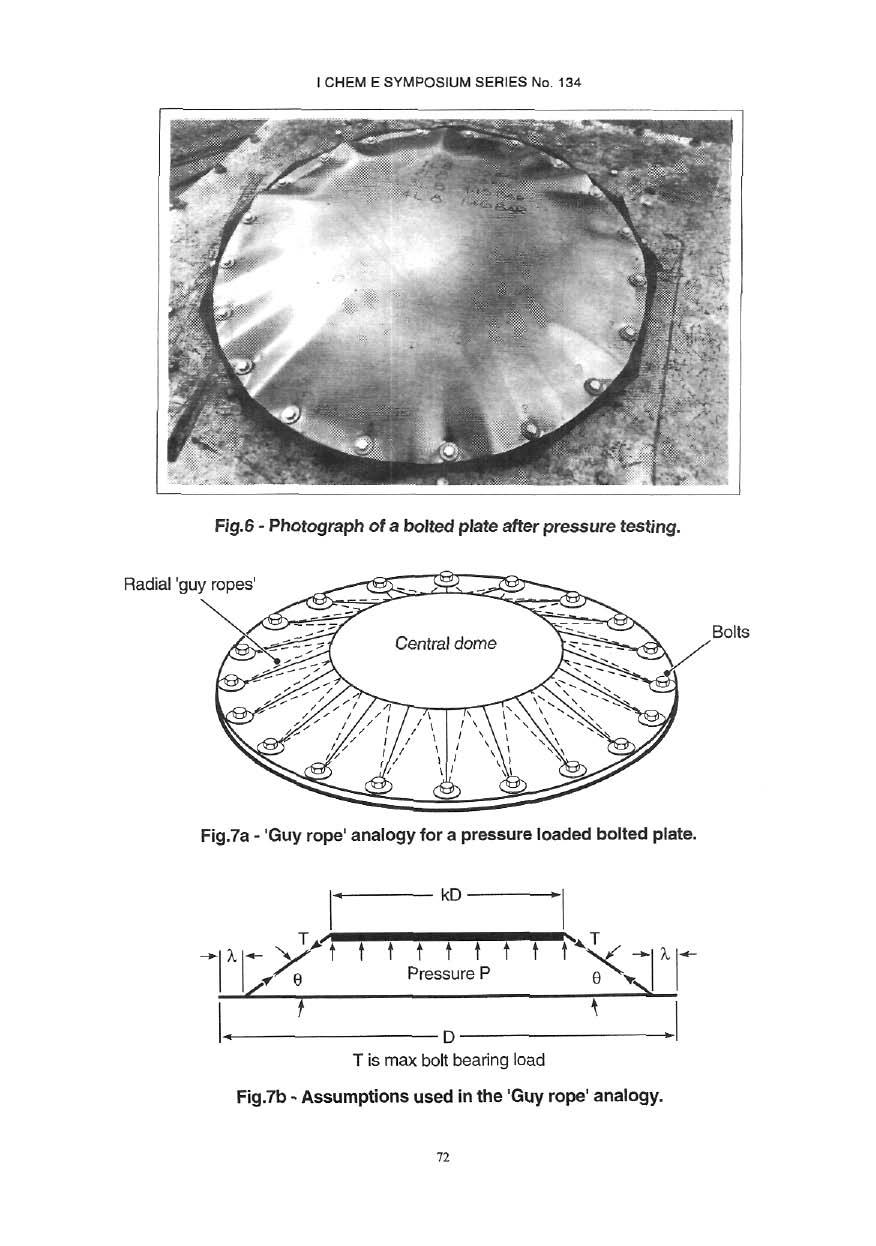
8 shape to that of a single test at the largest pressure on a virgin specimen. The rate of pressure rise was in the range bar/sec for these tests. It became apparent that neither of the modes of failures considered by PERA occurred for the size of plates tested. Failure was caused by the deformation of the plate material due to bearing stress, allowing the plate to pull from under the washers on the bolts so that only partial support of the washer was available. Bolt pull through then followed when the full support of the washer was no longer available. Shear-out failures were also recorded. Plate deformations involved large inward radial movements of the edge, enabling the necessary bulge to develop, with only a small central area of the plate reaching the yield stress. This deformation results in circumferential buckling of the plate between bolts. This buckling will carry some of the applied pressure load. It is this mode of failure which is investigated in this paper. 4,3 Additional Theory Any theory has to be based on the changes in geometry as witnessed, the simplest relationship being between the hole elongation, due to non-catastrophic bearing failure, and the central out-of-plane displacement. A simple geometric relationship between radial edge movement, X, and central displacement, 8, can be obtained with the following assumptions :- 1) the plate bulge is directly caused by bearing failure at the bolt holes with the yield stress of the material not being reached away from the bearing area, 2) the edge of the plate moves in-plane and is free to rotate; 3) the plate curvature can be considered as part of a sphere of radius R; 4) The radial tensile loads developed at the bolts are uniformly distributed around the plate edge; and, 5) all rotations are small allowing series expansion of trigonometric functions. Using the notation used in fig 5, the resulting equation, reduced to its simplest form, gives :- The equilibrium equation, based on these assumptions, was developed, relating the pressure to radial movement. Its correlation with experimental results was extremely poor, however, and it is not presented. The current test series on two sizes of circular plate provided visual and photographic evidence of the actual deformed shape. This indicated that only the central area of the plates could be considered as a spherical cap with the outer annulus being subjected to circumferential buckling. This is indicated in fig 6, where it can be seen that the tension developed at the bolts 64
9 appears to be transmitted directly to the central dome. Assumptions 3) and 4) are therefore invalid and must be replaced, for equilibrium consideration, by :- 1) the deformed shape consists of three straight lines whose total length remains unchanged and is equal to the original plate diameter, 2) the central 'dome' remains substantially flat, and 3) the radial tensile loads developed at the bolts are uniformly distributed around the central dome. The original geometric relationship between radial movement and central deflection isconsidered to remain valid as the central plate does become domed and errors are therefore likely to be small. The main assumption made in the present analysis is that the radial tension in the plate from the bolt to the edge of the central dome is constant. This implies that the pressure loading on the annulus is carried directly by the circumferential buckling stress system and not by radial tension. The behaviour of the full plate is therefore analogous to pressure applied to the 'central dome' only, supported by a system of 'guy ropes' as illustrated in figs 7a and 7b. Applying this concept to the analysis of the plate, however, requires an estimate of the resulting size of the central dome. Using simple geometric relationships and equilibrium between the pressure and the radial stresses the resulting simplified equation can be written as :- where This result is in terms of k, the ratio of central dome diameter/plate diameter, but P has a minimum value corresponding to k = 0.8, with all other parameters unchanged. With this value of k the equation reduces to :- Currently it is felt that some procedure for placing limits on the radial movement should be applied in order to rate the pressure strength of this feature. It is proposed that this is in terms of 65
10 the bolt diameter, washer outside diameter and the hole diameter. In the worst situation the minimum plate movement before the hole reaches the outside of the washer is :- Using this value of will result in a design pressure for the premature bolt pull through mode. Consideration of shear-out failure indicates that the distance from the bolt centre to the plate edge should be greater than the normally accepted value of twice the bolt diameter, say K x d. Assuming that the shear stress is and that the hole diameter is 1.1 x d then the limiting for shear-out failure in the worst condition is Using this value of λ will result in a design pressure for the shear out mode. 4.4 Further Expermental Work Two sizes of circular plate, 750 mm and 1220 mm diameter manufactured from 22 and 18 swg mild steel plate respectively, were progressively pressure tested. Tensile tests on the materials gave a yield stress of 300 N/mm 2 for both thicknesses. Extra-large diameter thick washers were manufactured for these tests so that large radial movement of the plate could be measured while the plate remained fully under the washer. Radial movement, at all bolt positions, and the central displacement were measured during progressive pressure testing. Previous experimental work with simple flat plates had indicated that progressive testing gave similar results to a single load test. To confirm this result some single tests were also carried out at the maximum pressure that had been applied progressively. Fig 8 shows a plot of the results for the geometric relationship, in non-dimensional form, of against for the 18 swg plates of both diameters. The theoretical line relationship, with a slope of 4/3 is also given. Fig 9 indicates how the theoretical radial displacement varied with pressure compared with the experimental results. Initial displacements will occur at very low load as all the hole clearances are taken up. Two 750 mm diameter plates of different thicknesses were tested to destruction with standard washers. The experimental results obtained were :- Thickness 22swg = mm Pressure =1.15 bar Thickness 18swg = mm Pressure = 1.79 bar Thickness ratio = 1.71 Pressure ratio =

11 4.5 Discussion of Results In order to verify that progressive testing produces valid results for analysis, the maximum possible rate of pressure rise possible was used for all these tests. Even at the high pressure rise rate used, bar/sec, the single pressure tests produced deformed shapes equivalent to those for tests at approximately 90% of the maximum progressively applied pressure. This implies that, for pressure rise rates generated in a dust explosion any dynamic effects will be a minimum once permanent deformations of the structure has occurred. It is therefore concluded that progressive testing is valid for this type of plastic deformation. Fig 8 indicates that the simple geometric relationship stated in section 4.3 between λ and δ is valid, the results for the smaller diameter plate being excellent. The larger diameter plates however, developed a central displacement without any radial edge movement. By applying standard classical elastic theory the stress in the central area of the plate can be shown to reach yield at very low pressures. This could explain the initial central displacement as this is likely to occur before bearing failure at the bolts starts. Figs 9a and 9b plot the radial edge movement against applied pressure for two different plates. They show both the theoretical relationship and the results obtained in testing. The theoretical results are based on a bearing stress of 600 N/mm 2 (ie twice yield stress) for different dome ratios (value of k) of 0.8, 0.6 and 0.5. From the experimental work, k was estimated as for the plates tested, see fig 6. The correlation between the experimental results and the theoretical results, assuming a value of k of is thought to be excellent considering the assumptions made for the development of a theory. For the specimens used K = 2.08 and for a bolt diameter of 12 mm the critical λ. for shear out is 3.6. The hole, bolt and washer combination used in the tests gives, a limiting value of λ = 4 mm. Because these values of λ are so close either mode of failure could apply and in fact both modes occured in both specimens tested. From the experimental results for the mm thick plate, shown in fig 9a, the value of λ = 4 mm would give a failure pressure of 1.3 bar. This correlates to a failure pressure of 1.15 bar as measured in a single pressure test. The theory predicts a failure pressure of 0.84, 1.06, and 1.36 bar when using k = 0.8, 0.6, and 0.5 respectively. 5. CONCLUSIONS The theoretical approach used by PERA to predict the strength of a circular plate with fully fixed edges has been verified under static pressure conditions. However, for weak vessel structures the condition of zero in-plane movement is never likely to be satisfied for non-circular plates. Great care must therefore be taken in applying this equation as in most cases the assumption of fixed edges will not be valid. For all bolted plates the PERA equations consider only the tensile failure of the bolts and the failure of the plate in shear due to bolt pull through. 67
12 The use of testing at progressively increased pressures seems to under-estimate the deformed shape when compared with a single test. This effect is greater at higher pressure rise rates, as would be expected, but at values of bar/sec the effect would appear quite small. This may be important but currently it is felt that a simple factor could be applied to take this into account. The use of the radial displacement versus pressure curve for a specific bolted plate joint geometry to predict failure pressure appears valid. On this assumption, an equation based on this approach has been presented and must be used together with equations for bolt failure and bolt pull through. Results of failure tests on two different thickness specimens indicate that the failure pressure of bolted plate joints could be proportional to plate thickness, with all other parameters the same, as indicated in the theory in 4.3. This work has successfully combined three different approaches and demonstrated the value of each of the them. The experimental work identified unusual plastically deformed shapes without which no theoretical approach could have been made; non-linear finite element analysis has proved extremely useful in verifying certain assumptions used in the development of theoretical equations and the theoretical approach has enabled the observed deformations to be quantified in readily usable equations. This investigation has highlighted the complex behaviour of certain features in weak vessels under internal pressure. The PERA equations represent a good groundwork for vessel rating, but require extending and modifying in the light of the results. Ultimately it is hoped that this work will contribute to the development of a guide to assist in the design of weak pressure vessels. UNITS 68
13 69
14 70
15 71
16 72
17 73
18 74
Plastic non-symmetric bifurcation buckling of circular cylinders under uniform external hydrostatic pressure
 icccbe 2010 Nottingham University Press Proceedings of the International Conference on Computing in Civil and Building Engineering W Tizani (Editor) Plastic non-symmetric bifurcation buckling of circular
Study to Establish Relations for the Relative Strength of API 650 Cone Roof Roof-to-Shell and Shell-to- Bottom Joints
 Thunderhead Engineering Consultants I N C O R P O R A T E D 1006 Poyntz Ave. Manhattan, KS 66502-5459 785-770-8511 www. thunderheadeng.com Study to Establish Relations for the Relative Strength of API
Analysis of Shear Lag in Steel Angle Connectors
 University of New Hampshire University of New Hampshire Scholars' Repository Honors Theses and Capstones Student Scholarship Spring 2013 Analysis of Shear Lag in Steel Angle Connectors Benjamin Sawyer
FEA case Study: Rubber expansion joint for piping systems
 FEA case Study: Rubber expansion joint for piping systems Introduction The FEA Toolbox of Taniq makes it possible to simulate the behavior of a pipe expansion joint accurately under several load cases.
2.1 Introduction to pressure vessels
 2.1 Introduction to pressure vessels Pressure vessels in the form of cylinders and tanks are used for storing variety of liquids and gasses at different temperatures and pressures. Some of the substances
Liquefied gas cargo tanks and process pressure vessels
 .1 -.3 Liquefied gas cargo tanks and process pressure vessels.1 General.1.1 The present texts give the general principles which are applied by Classification Societies for approval and survey of the relevant
OPENINGS AND REINFORCEMENTS 26
 ASME BPVC.VIII.1-2015 UG-35.2 UG-36 (4) It is recognized that it is impractical to write requirements to cover the multiplicity of devices used for quick access, or to prevent negligent operation or the
Design and Analysis of Pressure Safety Release Valve by using Finite Element Analysis
 Design and Analysis of Pressure Safety Release Valve by using Finite Element Analysis Mr.V.D.Rathod* 1, Prof.G.A.Kadam* 2, Mr.V. G. Patil* 3 * 1 M.E. Design (Pursuing), SKN Sinhgad Institute of Technology&
STRUCTURAL ANALYSIS OF THE VACUUM VESSEL FOR THE LHCb VERTEX LOCATOR (VELO)
") National Institute for Nuclear Physics and High Energy Physics Kruislaan 409 1098 SJ Amsterdam The Netherlands NIKHEF Reference no.: MT-VELO 04-1 EDMS no: 432626 OF THE VACUUM VESSEL FOR THE LHCb VERTEX
National Institute for Nuclear Physics and High Energy Physics Kruislaan 409 1098 SJ Amsterdam The Netherlands NIKHEF Reference no.: MT-VELO 04-1 EDMS no: 432626 OF THE VACUUM VESSEL FOR THE LHCb VERTEX
Bottom End-Closure Design Optimization of DOT-39 Non-Refillable Refrigerant Cylinders
 Y. Kisioglu a) Department of Mechanical Education, Kocaeli University, Izmit, Kocaeli, 41100, Turkey J. R. Brevick Industrial and Systems Engineering, The Ohio State University, Columbus, Ohio G. L. Kinzel
R.J.P. BARKER AND S.D. GUEST Cambridge University Engineering Department Trumpington Street, Cambridge CB2 1PZ, UK
 INFLATABLE TRIANGULATED CYLINDERS R.J.P. BARKER AND S.D. GUEST Cambridge University Engineering Department Trumpington Street, Cambridge CB2 1PZ, UK Abstract A study is described into the use of triangulated
FEA ANALYSIS OF PRESSURE VESSEL WITHDIFFERENT TYPE OF END CONNECTIONS
 FEA ANALYSIS OF PRESSURE VESSEL WITHDIFFERENT TYPE OF END CONNECTIONS Deval Nitin Bhinde 1 and Rajanarsimha S. 2 1 MTech CAD-CAM & Robotics, 2 Facculty, Department of Mechanical Engineering K.J. Somaiya
THIN CYLINDERS AND SHELLS
 CHAPTR 9 THIN CYLINDRS AND SHLLS Summary The stresses set up in the walls of a thin cylinder owing to an internal pressure p are: circumferential or hmp stress ah = longitudinal or axial stress al = -
Engineering Practice on Ice Propeller Strength Assessment Based on IACS Polar Ice Rule URI3
 10th International Symposium on Practical Design of Ships and Other Floating Structures Houston, Texas, United States of America 2007 American Bureau of Shipping Engineering Practice on Ice Propeller Strength
The tensile capacity of suction caissons in sand under rapid loading
 Frontiers in Offshore Geotechnics: ISFOG 25 Gourvenec & Cassidy (eds) 25 Taylor & Francis Group, London, ISBN 415 3963 X The tensile capacity of suction caissons in sand under rapid loading Guy T. Houlsby,
Corrugated Hose Loop Calculations
 Corrugated Hose Loop Calculations The loop installation is one of the most common application for metal hoses. It allows the flexible hose assembly to work properly. Care must always be exercised to ensure
Prof. B V S Viswanadham, Department of Civil Engineering, IIT Bombay
 43 Module 3: Lecture - 5 on Compressibility and Consolidation Contents Stresses in soil from surface loads; Terzaghi s 1-D consolidation theory; Application in different boundary conditions; Ramp loading;
Experimental Method to Analyse Limit Load in Pressure Vessel
 International OPEN ACCESS Journal Of Modern Engineering Research (IJMER) Dilip M. Patel 1, Dr. Bimlesh Kumar 2 1 Mechanical Department D.N.Patel COE, Shahada 2 Mechanical Department COE, Faizpur Abstract:
SHEAR PERFORMANCE OF RC FOOTING BEAMS BY CAP-TIE SYSTEM USING WELDED STIRRUPS
 The 7th International Conference of Asian Concrete Federation SUSTAINABLE CONCRETE FOR NOW AND THE FUTURE 3 Oct 2 Nov, 216, Hanoi, Vietnam www.acf216.vn SHEAR PERFORMANCE OF RC FOOTING BEAMS BY CAP-TIE
Structural Design of Tank Weighing Systems
 Structural Design of Tank Weighing Systems 1. Initial observations Some essential rules must be followed when installing load cells in tanks. For example, tanks are frequently subject to weather conditions
Vessels subject to External Pressure
 Basic principles of compressive force Vessels subject to External Pressure Before After The result of just air pressure! Presented by: Ray Delaforce Basic principles of compressive force Consider For a
Design and Safety Document for the Vacuum Windows of the NPDGamma Liquid Hydrogen Target at SNS
 Design and Safety Document for the Vacuum Windows of the NPDGamma Liquid Hydrogen Target at SNS Prepared: Checked: Approved: H. Nann W. Fox M. Snow The NPDGamma experiment is going to run at BL13 at SNS
Design and Optimization of Weld Neck Flange for Pressure Vessel
 V th International Symposium on Fusion of Science & Technology, New Delhi, India, January 18-22, 2016 ID: 2016-ISFT-430 Design and Optimization of Weld Neck Flange for Pressure Vessel Vinod Kumar 1, Vivek
Use equation for the cylindrical section and equation or for the ends.
 Solution 13.1 See section 13.3.4, equations 13.7 to 13.18 Solution 13.2 Use equation 13.34. (a) rigid constant C = 0.43 (b) free to rotate, C = 0.56 Solution 13.3 See section 13.5.1 Use equation 13.39
Stress evaluation of a bicycle crank arm connection using BEM
 Stress evaluation of a bicycle crank arm connection using BEM C. J. Hoff, R. E. Dippery & 3. Knapp Department of Mechanical Engineering Kettering University, USA Abstract An interesting problem encountered
ASSESSMENT AND ANALYSIS OF PIPELINE BUCKLES
 ASSESSMENT AND ANALYSIS OF PIPELINE BUCKLES GE Oil & Gas PII Pipeline Solutions Inessa Yablonskikh Principal Consultant Aberdeen, November, 14 th 2007 Assessment And Analysis Of Pipeline Buckles Introduction
Presented to the International Technical Rescue Symposium, November Abstract
 Presented to the International Technical Rescue Symposium, November 21 Presented by: Chuck Weber, PMI Quality Manager Abstract This paper presents the results of 162 individual drop tests performed at
ROUNDABOUT CAPACITY: THE UK EMPIRICAL METHODOLOGY
 ROUNDABOUT CAPACITY: THE UK EMPIRICAL METHODOLOGY 1 Introduction Roundabouts have been used as an effective means of traffic control for many years. This article is intended to outline the substantial
Advanced Hydraulics Prof. Dr. Suresh A. Kartha Department of Civil Engineering Indian Institute of Technology, Guwahati
 Advanced Hydraulics Prof. Dr. Suresh A. Kartha Department of Civil Engineering Indian Institute of Technology, Guwahati Module - 4 Hydraulics Jumps Lecture - 4 Features of Hydraulic Jumps (Refer Slide
Blast Damage Consideratons for Horizontal Pressure Vessel and Potential for Domino Effects
 A publication of CHEMICAL ENGINEERING TRANSACTIONS VOL. 26, 2012 Guest Editors: Valerio Cozzani, Eddy De Rademaeker Copyright 2012, AIDIC Servizi S.r.l., ISBN 978-88-95608-17-4; ISSN 1974-9791 The Italian
Type Testing Procedure for Crankcase Explosion Relief Valves
 (Jan 2005) (Corr.1 Nov 2005) (Rev.1 Oct 2006) (Corr.1 Mar 2007) (Rev.2 Sept 2007) (Corr.1 Oct 2007) (Rev.3 Jan 2008) Type Testing Procedure for Crankcase Explosion Relief Valves 1. Scope 1.1 To specify
Investigation of Stresses in Ring Stiffened Circular Cylinder
 International Journal of Engineering and Technical Research (IJETR) ISSN: 2321-869, Volume-2, Issue-9, September 214 Investigation of Stresses in Ring Stiffened Circular Cylinder Neetesh N. Thakre, Dr.
Lab # 03: Visualization of Shock Waves by using Schlieren Technique
 AerE545 Lab # 03: Visualization of Shock Waves by using Schlieren Technique Objectives: 1. To get hands-on experiences about Schlieren technique for flow visualization. 2. To learn how to do the optics
Safety and Longterm Accuracy of Bourdon Tube Pressure Gauges
 Technical Brief Safety and Longterm Accuracy of Bourdon Tube Pressure Gauges The demands of quality standards throughout the world such as ISO 9000 and BS5750 have led to the major pressure gauge users
Application of Computational Fluid Dynamics to Compressor Efficiency Improvement
 Purdue University Purdue e-pubs International Compressor Engineering Conference School of Mechanical Engineering 1994 Application of Computational Fluid Dynamics to Compressor Efficiency Improvement J.
Disc Wheel Rim: CAD Modeling and Correlation between FEA and Experimental Analysis
 Disc Wheel Rim: CAD Modeling and Correlation between FEA and Experimental Analysis Rahul Kumbhar 1 M Tech (CAD/CAM) student Department of Mechanical Engineering, Bharati Vidyapeeth Pune, Maharashtra, India
The Relationship between the Depth Embedded Pipe Pile and the Force of Clamping Jaw
 IOP Conference Series: Materials Science and Engineering PAPER OPEN ACCESS The Relationship between the Depth Embedded Pipe Pile and the Force of Clamping Jaw To cite this article: Yu Wentai et al 018
The Powerful Sealing Calculation
 KLINGER expert 6.0 The Powerful Sealing Calculation The KLINGER expert 6.0 gasket design program is a versatile software to assist users in the selection of non-metallic gasket materials. www.klinger.co.at
Finite Element Analysis of an Aluminium Bike Frame
 Finite Element Analysis of an Aluminium Bike Frame Word Count: 1484 1 1. Introduction Each new bike model must pass a series of structural tests before being released for public retail. The purpose of
Structural Design and Analysis of the New Mobile Refuge Chamber
 Key Engineering Materials Online: 2013-09-10 ISSN: 1662-9795, Vol. 584, pp 175-178 doi:10.4028/www.scientific.net/kem.584.175 2014 Trans Tech Publications, Switzerland Structural Design and Analysis of
Vertical Uplift Capacity of a Group of Equally Spaced Helical Screw Anchors in Sand
 SECM/15/080 Vertical Uplift Capacity of a Group of Equally Spaced Helical Screw Anchors in Sand S. Mukherjee 1* and Dr. S. Mittal 2 1 Amity University, Noida, India 2 Indian Institute of Technology, Roorkee,
Irrigation &Hydraulics Department lb / ft to kg/lit.
 CAIRO UNIVERSITY FLUID MECHANICS Faculty of Engineering nd Year CIVIL ENG. Irrigation &Hydraulics Department 010-011 1. FLUID PROPERTIES 1. Identify the dimensions and units for the following engineering
Mechanical Stabilisation for Permanent Roads
 Mechanical Stabilisation for Permanent Roads Tim Oliver VP Global Applications Technology Tensar International toliver@tensar.co.uk Effect of geogrid on particle movement SmartRock Effect of geogrid on
Serving. Petrochemicals Power Semiconductor Waste Treatment Oil & Gas Transmission Lines Bulk Gas Plants
 Serving Petrochemicals Power Semiconductor Waste Treatment Oil & Gas Transmission Lines ulk Gas Plants Mining & Metals Pharmaceuticals Pulp & Paper Mills Sugar Mills Nuclear Desalinization Plants NOTES:
TECHNICAL MEMORANDUM 3-81
 WOODS HOLE OCEANOGRAPHIC INSTITUTION Woods Hole, Massachusetts 02543 TECHNICAL MEMORANDUM 3-81 DESIGN PRESS CURVES FOR OCEANOGRAPHIC URE-RESISTANT HOUSINGS Prepared by Arnold G. Sharp August 1981 Office
A Study on the Eccentric Loading of K Node of Steel Tube Tower
 International Conference on Advances in Energy, Environment and Chemical Engineering (AEECE-2015) A Study on the Eccentric Loading of K Node of Steel Tube Tower LIU Haifeng a Wang Fei b Han Junke b Hu
Serving. Petrochemicals Power Semiconductor Waste Treatment Oil & Gas Transmission Lines Bulk Gas Plants
 Serving Petrochemicals Power Semiconductor Waste Treatment Oil & Gas Transmission Lines ulk Gas Plants Mining & Metals Pharmaceuticals Pulp & Paper Mills Sugar Mills Nuclear Desalinization Plants NOTES:
Analyses of the fuel cell stack assembly pressure
 Journal of Power Sources 145 (2005) 353 361 Analyses of the fuel cell stack assembly pressure Shuo-Jen Lee, Chen-De Hsu, Ching-Han Huang Department of Mechanical Engineering, Yuan Ze University, 135 FarEast
Applying Hooke s Law to Multiple Bungee Cords. Introduction
 Applying Hooke s Law to Multiple Bungee Cords Introduction Hooke s Law declares that the force exerted on a spring is proportional to the amount of stretch or compression on the spring, is always directed
Fatigue Life Evaluation of Cross Tubes of Helicopter Skid Landing Gear System
 IJSRD - International Journal for Scientific Research & Development Vol. 3, Issue 04, 2015 ISSN (online): 2321-0613 Fatigue Life Evaluation of Cross Tubes of Helicopter Skid Landing Gear System Madhu S
Figure 1 Schematic of opposing air bearing concept
 Theoretical Analysis of Opposing Air Bearing Concept This concept utilizes air bearings to constrain five degrees of freedom of the optic as shown in the figure below. Three pairs of inherently compensated
Other Si min/max. Cr min/max. 0.4/ / / / Bal.
 178.46 Specification 3AL seamless aluminum cylinders. (a) Size and service pressure. A DOT 3AL cylinder is a seamless aluminum cylinder with a imum water capacity of 1000 pounds and minimum service pressure
Pressure Integrity of 3013 Container under Postulated Accident Conditions
 Preprint of a paper published in Journal of Nuclear Materials Management, XXXVIII(3):43-53, 2010. Also available as SRNL-STI-2010-00053 Pressure Integrity of 3013 Container under Postulated Accident Conditions
Offshore platforms survivability to underwater explosions: part I
 Computational Ballistics III 123 Offshore platforms survivability to underwater explosions: part I A. A. Motta 1, E. A. P. Silva 2, N. F. F. Ebecken 2 & T. A. Netto 2 1 Brazilian Navy Research Institute,
AIAA Brush Seal Performance Evaluation. P. F. Crudgington Cross Manufacturing Co. Ltd. Devizes, ENGLAND
 AIAA 98-3172 Brush Seal Performance Evaluation P. F. Crudgington Cross Manufacturing Co. Ltd. Devizes, ENGLAND BRUSH SEAL PERFORMANCE EVALUATION AIAA-98-3172 P. F. Crudgington Cross Manufacturing Co. Ltd
STIFFNESS INVESTIGATION OF PNEUMATIC CYLINDERS. A. Czmerk, A. Bojtos ABSTRACT
 59 th ILMENAU SCIENTIFIC COLLOQUIUM Technische Universität Ilmenau, 11 15 September 2017 URN: urn:nbn:de:gbv:ilm1-2017iwk-148:6 STIFFNESS INVESTIGATION OF PNEUMATIC CYLINDERS A. Czmerk, A. Bojtos Budapest
High-Energy Ship Collision with Jacket Legs
 High-Energy Ship Collision with Jacket Legs Jørgen Amdahl Department of Marine Structures, NTNU, Trondheim, Norway Atle Johansen MARINTEK, Trondheim, Norway ABSTRACT Risk analysis of planned jacket installations
Rotary air valves used for material feed and explosion protection are required to meet the criteria of NFPA 69 (2014)
") Rotary air valves used for material feed and explosion protection are required to meet the criteria of NFPA 69 (2014) 12.2.4.2. 12.2.4.2 rotary valve design criteria (close clearance) 12.2.4.3 THE DESIGN
Rotary air valves used for material feed and explosion protection are required to meet the criteria of NFPA 69 (2014) 12.2.4.2. 12.2.4.2 rotary valve design criteria (close clearance) 12.2.4.3 THE DESIGN
Tightening Evaluation of New 400A Size Metal Gasket
 Proceedings of the 8th International Conference on Innovation & Management 307 Tightening Evaluation of New 400A Size Metal Gasket Moch. Agus Choiron 1, Shigeyuki Haruyama 2, Ken Kaminishi 3 1 Doctoral
Hatch cover securing and tightness
 (1986) (Rev 1 1996) (Corr.1 June 2000) (Rev.2 July 2005) (Corr.1 Oct 2005) Hatch cover securing and tightness 1. Application 1.1 The following recommendations apply to steel hatch covers that are fitted
Tresca s or Mises Yield Condition in Pressure Vessel Design
 Tresca s or Mises Yield Condition in Pressure Vessel Design Franz Rauscher Institute for Pressure Vessels and Plant Technology Vienna University of Technology Austria Why using Tresca s yield condition
SEALANT BEHAVIOR OF GASKETED-SEGMENTAL CONCRETE TUNNEL LINING
 4 th International Conference on Earthquake Geotechnical Engineering June 25-28, 2007 Paper No.1636 SEALANT BEHAVIOR OF GASKETED-SEGMENTAL CONCRETE TUNNEL LINING Faisal SHALABI 1, Edward CORDING 2, and
Analysis of dilatometer test in calibration chamber
 Analysis of dilatometer test in calibration chamber Lech Bałachowski Gdańsk University of Technology, Poland Keywords: calibration chamber, DMT, quartz sand, FEM ABSTRACT: Because DMT in calibration test
PTB Ex PT Scheme. Procedure Instruction of program Explosion Pressure - Test Round 2017
 Procedure Instruction of program Explosion Pressure - Test Round 2017 Content 1 General Performance... 2 2 Measurand / Characteristic of interest... 2 3 Test Item and Configurations... 2 3.1 Components...
P-04 Stainless Steel Corrugated Hoses and Metal Bellows Expansion Joints
 Guideline No.P-04 (201510) P-04 Stainless Steel Corrugated Hoses and Metal Bellows Expansion Joints Issued date: 20 th October 2015 China Classification Society Foreword This Guideline is a part of CCS
Application of pushover analysis in estimating seismic demands for large-span spatial structure
 28 September 2 October 2009, Universidad Politecnica de Valencia, Spain Alberto DOMINGO and Carlos LAZARO (eds.) Application of pushover analysis in estimating seismic demands for large-span spatial structure
Micro Channel Recuperator for a Reverse Brayton Cycle Cryocooler
 Micro Channel Recuperator for a Reverse Brayton Cycle Cryocooler C. Becnel, J. Lagrone, and K. Kelly Mezzo Technologies Baton Rouge, LA USA 70806 ABSTRACT The Missile Defense Agency has supported a research
Experiment (13): Flow channel
: Flow channel") Experiment (13): Flow channel Introduction: An open channel is a duct in which the liquid flows with a free surface exposed to atmospheric pressure. Along the length of the duct, the pressure at the surface
Experiment (13): Flow channel Introduction: An open channel is a duct in which the liquid flows with a free surface exposed to atmospheric pressure. Along the length of the duct, the pressure at the surface
MECHANICAL REDESIGN OF ION EXCHANGE RESIN VESSEL BOTTOMS AT HULETT REFINERY
 MECHANICAL REDEIGN OF ION EXCHANGE REIN VEEL BOTTOM AT HULETT REFINERY L MITH Tongaat-Hulett ugar Ltd E-mail: leon.smith@huletts.co.za Abstract A third party inspection failure of one of the flat bottom
SHAPA TECHNICAL PAPER 10 (Revised) SIZING OF EXPLOSION RELIEF VENTS DAVID BURN FIKE UK LTD
 SIZING OF EXPLOSION RELIEF VENTS DAVID BURN FIKE UK LTD") SHAPA TECHNICAL PAPER 10 (Revised) SIZING OF EXPLOSION RELIEF VENTS DAVID BURN FIKE UK LTD APRIL 2013 This article is written such that it creates a better understanding on the how explosion vent relief
SHAPA TECHNICAL PAPER 10 (Revised) SIZING OF EXPLOSION RELIEF VENTS DAVID BURN FIKE UK LTD APRIL 2013 This article is written such that it creates a better understanding on the how explosion vent relief
A New Piston Gauge to Improve the Definition of High Gas Pressure and to Facilitate the Gas to Oil Transition in a Pressure Calibration Chain
 A New iston Gauge to Improve the Definition of High Gas ressure and to Facilitate the Gas to Oil Transition in a ressure Calibration Chain ierre Delajoud, Martin Girard DH Instruments, Inc. 4765 East Beautiful
A parametric study of metal-to-metal contact flanges with optimised. geometry for safe stress and no-leak conditions
 A parametric study of metal-to-metal contact flanges with optimised geometry for safe stress and no-leak conditions M. Abid *, D. H. Nash a * Faculty of Mechanical Engineering, Ghulam Ishaq Khan Institute
CLASS D - SENSITIVE LEAK TEST GAS AND BUBBLE METHOD. 1.1 To provide definitive requirements for PNEUMATIC pressure testing of piping systems.
 Page 1 of 7 CLASS D - SENSITIVE LEAK TEST GAS AND BUBBLE METHOD 1. SCOPE 1.1 To provide definitive requirements for PNEUMATIC pressure testing of piping systems. 1.2 The piping system as used herein is
Elastic-Plastic Finite Element Analysis for Zhongwei--guiyang Natural Gas Pipeline Endangered by Collapse
 Abstract Elastic-Plastic Finite Element Analysis for Zhongwei--guiyang Natural Gas Pipeline Endangered by Collapse Gengxin Wu,Peng Zhang,Zhixiang Li,Zunhai Ke,Guizhi Li,Anmin Jiang 2 School of Civil Engineering
Design of submarine pressure hulls to withstand buckling under external hydrostatic pressure
 icccbe 2010 Nottingham University Press Proceedings of the International Conference on Computing in Civil and Building Engineering W Tizani (Editor) Design of submarine pressure hulls to withstand buckling
Bursting strength of paper. 1. Scope
 T 403 om-97 OFFICIAL STANDARD 1926 TENTATIVE STANDARD 1952 OFFICIAL STANDARD 1974 CORRECTED 1976 OFFICIAL TEST METHOD 1985 CORRECTED 1985 REVISED 1991 REVISED 1997 1997 TAPPI The information and data contained
An Innovative Solution for Water Bottling Using PET
 An Innovative Solution for Water Bottling Using PET A. Castellano, P. Foti, A. Fraddosio, S. Marzano, M.D. Piccioni, D. Scardigno* DICAR Politecnico di Bari, Italy *Via Orabona 4, 70125 Bari, Italy, scardigno@imedado.poliba.it
AIRFLOW GENERATION IN A TUNNEL USING A SACCARDO VENTILATION SYSTEM AGAINST THE BUOYANCY EFFECT PRODUCED BY A FIRE
 - 247 - AIRFLOW GENERATION IN A TUNNEL USING A SACCARDO VENTILATION SYSTEM AGAINST THE BUOYANCY EFFECT PRODUCED BY A FIRE J D Castro a, C W Pope a and R D Matthews b a Mott MacDonald Ltd, St Anne House,
CFD Simulation and Experimental Validation of a Diaphragm Pressure Wave Generator
 CFD Simulation and Experimental Validation of a Diaphragm Pressure Wave Generator T. Huang 1, A. Caughley 2, R. Young 2 and V. Chamritski 1 1 HTS-110 Ltd Lower Hutt, New Zealand 2 Industrial Research Ltd
Analysis of Pressure Rise During Internal Arc Faults in Switchgear
 Analysis of Pressure Rise During Internal Arc Faults in Switchgear ASANUMA, Gaku ONCHI, Toshiyuki TOYAMA, Kentaro ABSTRACT Switchgear include devices that play an important role in operations such as electric
Fail-Safe Design by Outer Cover of High Pressure Vessel for Food Processing
 Open Journal of Safety Science and Technology, 2011, 1, 89-93 doi:10.4236/ojsst.2011.13009 Published Online December 2011 (http://www.scirp.org/journal/ojsst) Fail-Safe Design by Outer Cover of High Pressure
Analysis of Pressure Safety Relief Valve using Finite Element Analysis
 Analysis of Pressure Safety Relief Valve using Finite Element Analysis 1 Mr. M. V. Awati, 2 Prof. S. G. Jadhav, 3 Vinay G. Patil 1 P.G.Student, 2 Proffessor, 3 Consultant 1 Mechanical Department, Veermata
Free Surface Flow Simulation with ACUSIM in the Water Industry
 Free Surface Flow Simulation with ACUSIM in the Water Industry Tuan Ta Research Scientist, Innovation, Thames Water Kempton Water Treatment Works, Innovation, Feltham Hill Road, Hanworth, TW13 6XH, UK.
Protecting your punching tool investment. Application-related problems and solutions
 Protecting your punching tool investment Application-related problems and solutions Article reprinted with permission from the May 2000 issue of The FABRICATOR. By Nick Tarkany Economic shortcuts in the
Determination of Burst Pressure of Spherical Shell
 International Journal for Ignited Minds (IJIMIINDS) Determination of Burst Pressure of Spherical Shell Balaji J a & Shivappa H A b a PG Student, Dept. of Mechanical Engineering,Dr. Ambedkar Institute of
STUDY OF UNDERWATER THRUSTER (UT) FRONT COVER OF MSI300 AUTONOMOUS UNDERWATER VEHICLE (AUV) USING FINITE ELEMENT ANALYSIS (FEA)
 FRONT COVER OF MSI300 AUTONOMOUS UNDERWATER VEHICLE (AUV) USING FINITE ELEMENT ANALYSIS (FEA)") STUDY OF UNDERWATER THRUSTER (UT) FRONT COVER OF MSI300 AUTONOMOUS UNDERWATER VEHICLE (AUV) USING FINITE ELEMENT ANALYSIS (FEA) M. Sabri 1, 2, T. Ahmad 1, M. F. M. A. Majid 1 and A. B. Muhamad Husaini
STUDY OF UNDERWATER THRUSTER (UT) FRONT COVER OF MSI300 AUTONOMOUS UNDERWATER VEHICLE (AUV) USING FINITE ELEMENT ANALYSIS (FEA) M. Sabri 1, 2, T. Ahmad 1, M. F. M. A. Majid 1 and A. B. Muhamad Husaini
Transient Analyses In Relief Systems
 Transient Analyses In Relief Systems Dirk Deboer, Brady Haneman and Quoc-Khanh Tran Kaiser Engineers Pty Ltd ABSTRACT Analyses of pressure relief systems are concerned with transient process disturbances
Gerald D. Anderson. Education Technical Specialist
 Gerald D. Anderson Education Technical Specialist The factors which influence selection of equipment for a liquid level control loop interact significantly. Analyses of these factors and their interactions
Fluid Machinery Introduction to the laboratory measurements
 Fluid Machinery Introduction to the laboratory measurements Csaba H s (csaba.hos@hds.bme.hu) Ferenc Hegedus (hegedusf@hds.bme.hu) February 21, 2014 1 Requirements related to the measurement part of the
Applied Fluid Mechanics
 Applied Fluid Mechanics 1. The Nature of Fluid and the Study of Fluid Mechanics 2. Viscosity of Fluid 3. Pressure Measurement 4. Forces Due to Static Fluid 5. Buoyancy and Stability 6. Flow of Fluid and
Abstract. 1 Introduction
 Buoyancy and strength of existing bulk carriers in flooded conditions J. Jankowski, M. Bogdaniuk, T. Dobrosielski Polski Rejestr Statkow, Gdansk, Poland Email: tk@prs.gda.pl Abstract Bulk carriers have
2003 WJTA American Waterjet Conference August 17-19, 2003 Houston, Texas Paper PIPE THREADS-WHAT IS THE LIMIT?
 23 WJTA American Waterjet Conference August 17-19, 23 Houston, Texas Paper PIPE THREADS-WHAT IS THE LIMIT? D. Wright, J. Wolgamott, G. Zink StoneAge, Inc. Durango, Colorado, U.S.A. ABSTRACT At present
ICHEME SYMPOSIUM SERIES NO. 144
 EXPLOSION VENTING - THE PREDICTED EFFECTS OF INERTIA By Steve Cooper - Stuvex Safety Systems Limited Explosion venting is an established and well used method of primary explosion protection within industry.
End of Chapter Exercises
 End of Chapter Exercises Exercises 1 12 are conceptual questions that are designed to see if you have understood the main concepts of the chapter. 1. While on an airplane, you take a drink from your water
Flow in a shock tube
 Flow in a shock tube April 30, 05 Summary In the lab the shock Mach number as well as the Mach number downstream the moving shock are determined for different pressure ratios between the high and low pressure
Two interconnected rubber balloons as a demonstration showing the effect of surface tension
 Two interconnected rubber balloons as a demonstration showing the effect of surface tension Abstract Science One 28-9 CHEN, Chieh-Shan The two interconnected rubber balloons system is a demonstration widely
THE BRIDGE COLLAPSED IN NOVEMBER 1940 AFTER 4 MONTHS OF ITS OPENING TO TRAFFIC!
 OUTLINE TACOMA NARROWS BRIDGE FLOW REGIME PAST A CYLINDER VORTEX SHEDDING MODES OF VORTEX SHEDDING PARALLEL & OBLIQUE FLOW PAST A SPHERE AND A CUBE SUMMARY TACOMA NARROWS BRIDGE, USA THE BRIDGE COLLAPSED
New Findings for the Application of Systems for Explosion- Isolation with Explosion Venting
 529 A publication of CHEMICAL ENGINEERING TRANSACTIONS VOL. 48, 2016 Guest Editors: Eddy de Rademaeker, Peter Schmelzer Copyright 2016, AIDIC Servizi S.r.l., ISBN 978-88-95608-39-6; ISSN 2283-9216 The
OIL AND GAS INDUSTRY
 This case study discusses the sizing of a coalescer filter and demonstrates its fouling life cycle analysis using a Flownex model which implements two new pressure loss components: - A rated pressure loss
THEORETICAL EVALUATION OF FLOW THROUGH CENTRIFUGAL COMPRESSOR STAGE
 THEORETICAL EVALUATION OF FLOW THROUGH CENTRIFUGAL COMPRESSOR STAGE S.Ramamurthy 1, R.Rajendran 1, R. S. Dileep Kumar 2 1 Scientist, Propulsion Division, National Aerospace Laboratories, Bangalore-560017,ramamurthy_srm@yahoo.com