W I L D W E L L C O N T R O L COMPLETIONS AND WORKOVERS
|
|
|
- Rosemary Harmon
- 5 years ago
- Views:
Transcription


1 COMPLETIONS AND WORKOVERS
2 Completions & Workovers Learning Objectives You will learn - The reasons why a well needs to be worked over. The benefits derived from working a well over. To prepare a well completion. To design a completion for the type of reservoir. The types of well completion equipment. You will also learn - The surface completion equipment needed. The downhole completion equipment needed. You will also review how to control and kill live wells. W I L D W E L L C O N T R O L
3 Completions & Workovers Overview We will design the well from start to finish. We will review ways to work the well over. We will utilize kill methods. We will review different workover methods. We will review methods to keep operators on track for proper workover procedures.
4 Completion Design The completion designed can be broken into five phases Establishing design criteria. Preparation of the production zone. Mechanical completion of the well. Initiate production and apply treatment procedures. Monitoring & assessment of the wells and the performance of the completion.
5 Completions & Workovers Integrating the five phases - Efficient completion is a complex process. Must use a rigorous approach to establish design criteria. Comprehensive formation evaluation program is essential Well completion design is a dynamic process, it must include - Feedback from completion performance data. Changes in design criteria.
6 Completions & Workovers Design process to allow flexibility for operational requirements and uncertainties in available design data. Completion has limited number of specific tubular components. Overall number of components affects complexity of completion and its reliability.
7 Well Completion Tips When arriving on location - Count the joints of tubing. Number all joints of tubing. Rabbit the joints of tubing. Check the threads and pin ends. Lubricate the tubing joints. Check the completion equipment. Check the I.D. to ensure it is the proper diameter for the completion string.
8 Well Completion Tips If running a combination of nipples, (selective and NO-GO), be sure that you know how to install them correctly. If installing hydraulic, or hydrostatic set packers, check I.D s, check that all shear pins are in place and none are missing. Bi-Directional slips - Check that slips are functioning correctly. - May not be aligned properly. - Will only move part way. - Will keep the packer set from below. Ensure bi-directional slips are aligned properly.
9 Well Completion Tips Check that the packer has a setting port drilled into the inner mandrel of the packer. Know the setting area of the packer. Calculate the setting force needed - Setting force lbs = Setting area sq. in. x Hyd. setting pressure psi The actual depth that the packer will be set should be measured from the sealing elements. Now the completion string is run and installed. Note: the completion string is not only a mechanical hookup that you are putting inside of the wellbore; It is also pressure vessel.
10 Well Completion Tips Several small things done incorrectly will lead to failures. Normal completion string running speed is a stand per minute. If more than 10% of dead hanging weight is lost, then it is being run too fast. This can cause the well to be surged. If running a hydraulic or hydrostatic set packer, do not run setting ball or standing valve in place. The water hammer effect will prematurely set the packers, because it will shear the setting pins. When landing the completion string, be sure that the seal on the tubing hanger is in good working shape.
11 Well Completion Tips Always have a back pressure valve installed in the tubing hanger. When removing the back-pressure valves, NEVER dry rod the back pressure valve from the tubing hanger. Always install a lubricator for pressure control. Drilling fluid in well can be circulated out with the completion fluid after the X-mas tree is installed. Packers with metal fold back rings on each end of the sealing elements will protect them from pump pressure wear. A circulating rate of about one bpm is a good rate when displacing fluids.
12 Well Completion Tips Drilling fluid displacement can be done either with forward or reverse circulation when using a hydraulic set packer. If the packer is a hydrostatic set packer, you can only displace it by reverse circulation. Forward circulation will set packer prematurely. A surging rig pump should never be used to displace drilling fluid as it is possible to prematurely set a hydraulic or hydrostatic packer. Ensure hydraulic and hydrostatic set packers are at proper setting depth before you starting displacement. You must have a circulating device (sliding sleeve, SPM) installed in tubing string.
13 Well Completion Tips If you don t know why a certain type of packer is used, then check with your supervisor. Know the setting mechanism of the packers, how it sits, and learn the problems you can encounter. Set hydraulic or hydrostatic packers with a ball if the formation will take fluid. Don t use a ball to set packers if the formation won t take fluid. Use a standing valve or hydrotrip sub to set packers.
14 Well Completion Tips When installing a single well with multiple production zones, ensure there is no tubing movement between packers. If tubing movement is present install expansion joints between packers. If the well has been installed for gas lift, do not inject gas too fast and cut out the gas lift valves. Do not restrict the flow by installing too many 90o angles in the flow line; streamline the flow line. Always install a positive choke in the flow line. All wells under MMS regulations must be installed with surface controlled sub surface safety valve.
15 Well Completion Tips SCSSVs must be installed at a depth below the mud line to give protection in case of an impact or explosion at surface. (MMS dictates SCSSVs must be installed 100 feet below the mudline) Place circulation devices one joint above packer, never directly on top. Do not circulate too fast through sliding sleeves or side pocket gas lift mandrels. Fast circulation cuts sleeves and mandrels out. If setting hydraulic set packers, do not use the bottom layers of barite weighted mud as weight may not be consistent.
16 Well Completion Tips Run tubing conveyed perforator below packers. Use tubing string weight and hold back pressure on top of packers. This keeps from blowing the completion string up the hole. If using an equalizing standing valve to set hydraulic set packers, the standing valve has to be equalized before it is pulled. Always install two way check valve in the tubing hanger to pressure test the X-mas tree and valves.
17 Packers Types of Packers Permanent Permanent Retrievable Mechanical Set Hydraulic Set

18 Permanent Packers High Temp Sump Packer Tubing Set Hydraulic Set Wireline Set
19 Permanent Packers Scoop Head Design Overshot Seal Guide Internal Locking Slips J Latch Receiving Head Internal Locking Slips Case Carburized Upper Slips Triple Slips Multi- Durometer Package Sealing Bore Triple-Seal Multi- Durometer Element Package Setting Sleeve Cylinder Wireline Set Packer Metal Back-up Shoes Case Carburized Lower Slips Hydraulic Set Packer Setting Piston Setting Rotation Feature Tubing Set Packer W I L D W E L L C O N T R O L

20 Permanent Packers Mandrel Case Carburized Upper Slips Case Carburized Lower Slips Severe Environment Packer Hi-Temp Element Package
21 Typical Permanent Packer Hydraulic Set Wireline Set
22 Packers Designed for single-string completions. For emergency pulling, straight pull will unseat the packer.

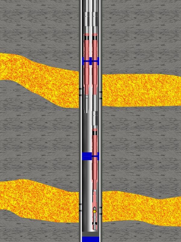
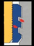
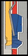
23 Isolation Packer What are the advantages of using an isolation tool squeeze packer? Face seal unloaded (valve) located at the top of the tool seals off the inside tubing. Has a built-in balance sleeve system that holds the valve closed when tubing psi is greater than the annular psi. By-pass system, located at top of the packer allows circulation above packer. Three piece sealing element. Jay slot and slips located below sealing elements holds the packer and prevents downward movement. Water Level Section of sand to be squeezed
24 Isolation Packer Q&A #1 This well has 3 productive zones. The company wants to acid/frac each zone, clean them out, set a packer and tubing string as a production string. What type of packer must you use? Answer - The type of packer must be a hook wall packer with hydraulic hold down buttons.
25 Isolation Packer Q&A #1 Can all these things be accomplished in one trip or must you make several trips? Yes they can if you do not have a thief zone (in this case all 3 zones have the same pressure with shale stringers between the productive sands). After fracing the zone, the packer is released. Then, wait until the sealing element returns to its original shape or as close as possible. (approx mins or a cup of coffee and two cigarettes)
26 Isolation Packer Next, lower the unseated packer down hole slowly and reverse out the excessive debris. Then, pick up the packer above the zones after cleaning them up and reset the packer. Depending upon what type of packer is selected, release and re-set. (the packing elements will try to return to their original position)

27 Isolation Packer Wire line Set Cement Retainer Model K-1 Wire line Set Cement Retainer With Flapper Valve Model K-1 Mechanical Set Cement Retainer Model K-1 Mechanical Set Bridge Plug Model N-1 Mechanical Set Cement Retainer w/flapper Valve Model K-1

28 Packers Hydraulically Set Retrievable Packer The packer is set hydraulically by pressuring up on tubing against a check valve located below packer. The packer can also be set with a standing valve, positive wireline-set plug or a hydrotrip sub.
29 Packers Hydraulically Set Retrievable Packer Packer is retrieved by a straight pull on the tubing string. Catcher subs accept a brass ball as a check valve. Expendable catcher sub is normally used.
30 Packers Expendable Catcher Sub Hydraulically Set Retrievable Packer
31 Setting Hydraulic Packer w/pump Out Sub 2-3/8 OD Tubing Tubing Fluid Diesel 7.0 ppg Hydraulic Set Packer Annular Fluid Brine 10.0 ppg Casing 7 OD 6.25 ID Ball Perforations open but not taking fluid. Tight Gas Sand Tight Gas Sand Bridge Plug
32 Setting Hydraulic Packer w/pump Out Sub How much Force (lbs) is exerted under the packer? To release the ball we need 4,000 psi of pressure. Force lbs. = Area x Well Pressure = ID2csg in x x Well Pres. = in x x 4,000 psi = 122,719 lbs force 2-3/8 OD Tubing Tubing Fluid Diesel 7.0 ppg Casing 7 OD 6.25 ID Ball Tight Gas Sand Hydraulic Set Packer Annular Fluid Brine 10.0 ppg Perforations open but not taking fluid. Tight Gas Sand Bridge Plug

33 Setting Hydraulic Packer w/pump Out Sub Ball goes down and hits bridge plug. This allows communication with the production zone and the tubing. Bridge Plug

34 Setting Hydraulic Packer w/pump Out Sub Force travels up. Full impact of the pressure is exerted on the packer.
35 Setting Hydraulic Packer w/pump Out Sub Impact blows and unseats the packer and moves with the completion string up hole.
36 Setting Hydraulic Packer w/pump Out Sub Typical Retrievable Packers Single Hydraulic Packer Dual Hydraulic Packer
37 Packers Baker Model FH packer is hydrostatically set with a field adjustable shear release mechanism. To set packer a ball, standing valve, hydrotrip sub, or a positive plug must be installed below the packer. Model FH Packer
38 Packers Model DAB packer can serve as Baker Model FH packer is hydrostatically set with a field adjustable shear release mechanism. Production packer Zone isolation packer Reliable squeeze packer Model DAB Packer
39 Packers Hydrostatic-Set Packer This packer type is designed to be run and set in - Highly deviated wellbores. Horizontal wellbores When conventional running and setting techniques are difficult to achieve. It uses existing hydrostatic pressure of the wellbore to set the packer.
40 Packers The Type BB packer is a retrievable packer that can be run on - Conventional electric line Slickline Coiled tubing Conventional workstring BB

41 Tubing Conveyed Perforating The tubing conveyed perforating tool is run below the packer with the tubing.

42 Tubing Conveyed Perforating Gun is fired by dropping firing bar after setting packer.

43 Tubing Conveyed Perforating Displace drilling fluid with completion fluid.
44 Tubing Conveyed Perforating Well bore is charged from the perforations by 7,000 psi of formation pressure after perforating.

45 Tubing Conveyed Perforating Pressure from the formation returns and travels downwards and upwards.

46 Tubing Conveyed Perforating Forces then rebound. Now calculate the force underneath the packer.
47 Tubing Conveyed Perforating Force = (ID, in.) 2 x x Pressure, psi = (6.25) 2 x x 7,000 = 214,758 pounds Plus 50,000 pounds shock force (from firing perforating tool) Total Force = 214, ,000 = 264,758 lbs
 Bursts casing at packer")
48 Tubing Conveyed Perforating Force travels up - Corkscrews tailpipe (tubing below packer) Bursts casing at packer seal

49 Tubing Conveyed Perforating Tubing is - Corkscrewed Packer is - Unseated Blown up hole
50 Permanent Packer Accessories Extension Anchor Latch G Locator Anchor Latch Locator Seal Assembly Seal Extension K22 Anchor Seal Nipple EBH22 Anchor Seal Assembly
51 Single String Multi-Zone Completion These types of completions have been run. Experience has taught us to make sure that the packers were always at the proper setting depths. Selective Set Packers Zone 2 Zone 1 Sliding Sleeves Zone 3 Hydraulic Set Packer Zone 4 NoGo Nipple w/ Standing Valve The shifting tools were run. The top to shift down to open the sleeve. The lower shifting tools shift upward to close.

52 Dual Completion Too much weight was set on the packer which caused the short string to corkscrew. What s a possible solution?
53 Dual Completion The sliding sleeve in the long string was opened below the dual packer. The plug had to be pumped down by a pump truck, because the tubing was corkscrewed. The plug was set. The pump was swapped to the long string and pressured up below the plug in the short string. The upward force removed some of the weight from the short string and the packer set.
54 Dual Completion

55 Landing Nipples and Key Profiles

56 Landing Nipples and Key Profiles Key Profile Seal Bore NO-GO Type X Type XN

57 Landing Nipples and Key Profiles Key Profile Seal Bore Type X Type XN Type RN


58 Down hole Safety Valve Nipple The nipple, left, has a sliding sleeve which prevents solids blocking the control line port when valve is out of the hole. Standard nipple, right, lacks the inner protective sleeve. The sleeve shifts each time the valve is set or pulled. When the valve is set, a shifting mandrel attached to the locking mandrel shifts the sleeve open. Sleeve closed when safety valve is pulled from nipple.
59 Down hole Safety Valve Nipple Sleeve closed when safety valve is pulled from nipple. A shifting tool can open sleeve prior to setting the wireline safety valve in the nipple. The control line then attaches to the tubing hanger and is accessible via a needle valve mounted to the tubing spool. The control line of ¼ SS tubing attaches to the nipple and is strapped to the tubing as it is made up and run in the hole. In deep set safety valves an additional hydraulic line is attached to this valve to enable increased hydraulic fluid and pressure to be supplied. This becomes a necessity in deep set safety valves.


60 Tubing Nipples and Lock Mandrels Production tubing nipples are special tubulars made up as part of the production string incorporating a machined profile into which specific locking devices can be set. Pictured at left is a Position 1 S Lock Mandrel and its companion nipple. The nipple and mandrel are said to be selective as per the nipple profile and matching locator key profile. There are numerous positions for this type of nipple and locking device which allows freedom as to the specific nipple and depth a flow control device will be set. Shown below is an example of varying positions available for this equipment. The locator portion of the nipple is machined to a specific profile and matching locator keys are installed on the locking device. The locking device will only set and lock in its matching nipple. Lock Mandrel and S Nipple


61 Tubing Nipples and Lock Mandrels
62 Tubing Plug Another form of a positive plug is one that is run on an S or T locking device. The prong, once again, serves as an equalizing device, but in this case, it is run with the plug body as the prong is pinned to the valve. Upward Prong Movement Adapter Sub Valve Shear Pin Valve Stem PS Plug
63 Tubing Plug Pulling of the plug entails two trips in the hole. The first trip to pull the prong achieving pressure equalization and the second trip retrieves the locking mandrel and the plug. Upward Prong Movement Adapter Sub Valve Shear Pin Valve Stem PS Plug
64 X & XN Wireline Landing Nipples Orientation Groove Key Profile Orientation Groove Key Profile Seal Bore Seal Bore Trash Groove No-Go Shoulder X Selective Landing Nipple XN NO-Go Landing Nipple
65 Flow Coupling and Blast Joint Flow Couplings and Blast joints are Specialty tubulars w/ thicker walls to protect the completion string. Flow Coupling Blast Joint
66 Flow Couplings Flow couplings eliminate turbulence existing above and below a nipple due to its restriction. Installed above and below tubing nipples. Thicker walls resist erosion better. Flow Coupling Placement Landing Nipple & Flow Control Device Flow Coupling
67 Blast Joints Placed in tubing string opposite, open and at flowing perforation or tubing hanger depth. At both of these depths there is extreme flow which can cause tubular erosion. Protect tubing from Excessive wear Premature failure Flow Coupling Blast Joint Flow from well Landing, or Polished Nipple
 All nipples run in")

68 Tubing Nipples and Mandrels Tubing Nipples are selective as per the running tool. (this allows bypassing of shallower nipples to set nipples at the desired depth) All nipples run in the tubing of this type ( CAMX ) have the same profile with the exception of the NO-GO nipple containing the NO-GO restriction. Fishing Neck Expander Mandrel Double Acting Spring Locking Keys Packing Nipple & Lock Mandrel


69 Tubing Nipples and Mandrels The running tool used to run and set the equipment allows the operator to select a specific depth to install flow control devices based on various depth of the nipples.
70 Tubing Plug The AX is a plug installed on an CAMX locking mandrel. The plug body, made up of the lock mandrel, equalizing sub, and valve cap are run and set in the desired CAMX nipple. Prong Weldment Lock Mandrel Upward Prong Movement Equalizing Prong Element Equalizing Prong Housing Element Equalizing Prong Housing Valve Cap PX Plug
71 Tubing Plug A standard pulling tool is run to retrieve the prong for equalization. Another trip is made to pull the plug body. Prong Weldment Lock Mandrel Upward Prong Movement Equalizing Prong Element Equalizing Prong Housing Element Equalizing Prong Housing Valve Cap AX Plug


72 Nipples and Mandrels The CAMXN (locking) nipple has a NO-GO ring machined into the bottom. This allows only a mandrel with a No-Go ring to be installed. This nipple is the lowest run in the tubing string because of the presence of the NO-GO restriction. Running Neck Running Neck Locking Dogs Locking Profile V-Type Packing NO-GO Restriction NO-GO Ring Nipple and Lock Mandrel


73 Locking Device: Landing Nipple/Safety Valve

74 Locking Dogs Two types of locking dogs for the selective and the NO-GO nipples.
75 Circulating Devices Sliding Sleeve Circulating devices Production devices Side pocket mandrel MM series KB series
76 Sliding Sleeve A SS is a window placed as a part of the completion string which allows communication with annulus. Opening or closing the sleeve is with a shifting tool which locates in a machined profile in the inner sleeve.
77 Sliding Sleeve A nipple profile can be installed above the SS. This profile is used to blank (close) off the ports by installing an isolation tool. The same is true when, you want to produce through the SS then, a separation tool is installed in the nipple profile. NOTE: Sliding sleeves are installed to open up or down, depending on the application. W I L D W E L L C O N T R O L

78 Sliding Sleeves Ball Ball Seat Seat Recess Sliding Sleeve Hydraulic Opening Port Inner Mandrel Running Circulating Closing Drilling Fluid Bottom Hole Pressure Lock Ring Activating Spring W I L D W E L L C O N T R O L Universal Circulating Sleeve
79 SS and Shift Tools The pin x pin B shift tool may be run so the sleeve can open either direction this dictates how the shifting tool is run. Landing Nipple Inner Sleeve Equalizing Port Seals Body Threads B Shifting Tool Durasleeve Type XA Sleeve
80 SS and Shift Tools The right angle shoulders of the locator keys match a machined profile in the sleeve. After the sleeve has shifted, the tool releases from the shifting profile. Landing Nipple Inner Sleeve Equalizing Port Seals Body Threads B Shifting Tool Durasleeve Type XA Sleeve

81 Side Pocket Valves

82 Latches Latch Latch Dome Seals Dome Seals Dome Bellows Packing Dome Packing Bellows Seal Stop Stem Lift Pin Pilo Port Stem Seal Stop Tapered Stem Ball Stem Seat Packing Pilo Port Control Port Seat Reverse Check Valve Reverse Check Valve W I L D W E L L C O N T R O L RA Latch Packing BK Latch
83 Question & Answer Q&A #1 A side pocket mandrel has been run in the horizontal part of the well in the next slide and has rotated to the top side of the well bore. When the well was completed, the design engineer was told to be sure the well could be worked over and killed by circulating through the side pocket gas lift mandrel. Study this drawing and give the design engineer the proper methodology to establish communication between the tubing and annulus.

84 Question & Answer W I L D W E L L C O N T R O L Q&A #1
85 Question & Answer Q&A #1 What are your recommendations? Wireline and coil tubing are poor choices. The correct way would be to install a dump kill valve (this is a burst disc one way valve) in the side pocket mandrel and open it by applying pressure on the annulus.
86 Gas Lift Equipment and Systems One type of gas lift which can be installed in wells that were not initially completed with gas lift equipment is a gas lift packoff. Rather than pulling the tubing, packoff type gas lift assemblies can be installed. Lift Gas Upper Fish Neck Slip-Type Stop Centralizers Upper Packoff Well Fluid Perforation Gas Lift Valve Centralizers Lower Packoff Collar Stop Slip-Type Know Concentric Packoff Gas Lift Assembly
87 Gas Lift Equipment and Systems The tubing is perforated at the desired depths and the assemblies as seen at left are installed opposite the perforations. Installation and servicing of the equipment can be performed by wireline or coiled tubing. In the illustration slip type stop devices are used to hold the assembly in place but, as seen in the inset at lower left, collar locks can be used as well usually as the lower stop with a slip stop at the top of the packoff. Lift Gas Well Fluid Upper Fish Neck Slip-Type Stop Centralizers Upper Packoff Perforation Gas Lift Valve Centralizers Lower Packoff Collar Collar Slip-Type Stop

88 Old Type Kick-Over Tools The appropriate pulling or running tool for the gas lift valve would be installed below the kick-over tool. Camco Kick-over Tools AK L L-2D
89 Down-hole Safety Valves The Series 10 Flapper Valve is hydraulic valve, NC (normally closed) operated from the surface. Full bore to tubing on which it is installed.
90 Down-hole Safety Valves Allows servicing of well thru safety valve. Valve has a lock-out feature In the event the valve becomes inoperative, the internal safety valve nipple may be used after the tubing retrievable safety valve has been locked out.

91 Kickover Tool Kickover Tool Running and Retrieving Tools for Side Pocket, Mandrels, Kick over Tool.
92 Safety Valve The safety valve is a NC valve which must have hydraulic pressure supplied in order to operate. Lock-out feature capability for the installation of a wireline valve The flow tube protects the flapper during well production Lock Open Communication System Eliminates Construction Seals Hydraulic/Spring Chamber Not Exposed to Well Fluids Full MTM Flapper and Seat System Tubing Retrievable Safety Valve
93 Storm Choke (Velocity Valve) Equalizing Sub The Storm Choke (velocity valve) is a direct-controlled, normally open valve - Spring and spacers determine the spring force used to hold valve open. When pressure differential across valve reaches a pre-determined point and is less then spring tension, valve closes. Lock Mandrel Landing Nipple Equalizing Sub Top Sub Back-Up Ring O-Ring Spring Valve Cage Piston Spacer(s) Cage Adapter Spring Ball Retainer Ball Body Weldment Bean Ball and Seat Top Sub Back-Up Ring O-Ring Spring Valve Cage Piston Spacer(s) Cage Adapter Spring Ball Retainer Ball Body Weldment Bean Ball and Seat
94 Storm Choke (Velocity Valve) Equalizing Sub To reopen the valve, pressure is applied to the tubing or an equalizing prong can be run into the valve and equalizing sub. The valve, right, is attached to an X locking mandrel but can be attached to many different types of locking devices. Lock Mandrel Landing Nipple Equalizing Sub Top Sub Back-Up Ring O-Ring Spring Valve Cage Piston Spacer(s) Cage Adapter Spring Ball Retainer Ball Body Weldment Bean Ball and Seat Top Sub Back-Up Ring O-Ring Spring Valve Cage Piston Spacer(s) Cage Adapter Spring Ball Retainer Ball Body Weldment Bean Ball and Seat
95 Ambient Storm Choke Equalizing Sub The Storm Choke is an ambient, normally open valve, pre-charged with a set dome pressure. Usually, used in deep setting operations. When flowing pressure of well drops below the dome pressure, dome pressure and valve spring close valve. Lock Mandrel Equalizing Sub Top Sub Back-Up Ring O- Ring Piston Spring Chamber Screw Gasket Back-Up Ring O-Ring Body Weldment Ball and Seat Top Sub Back-Up Ring O-Ring Piston Spring Chamber Screw Gasket Back-Up Ring O-Ring Body Weldment Ball and Seat
96 Ambient Storm Choke Equalizing Sub Valve reopens when tubing pressure returns above dome pressure. This is done by applying surface pressure above valve, or by running an equalizing prong and equalizing pressure across the valve. It can be attached to many types of locking devices. W I L D W E L L C O N T R O L Lock Mandrel Equalizing Sub Top Sub Back-Up Ring O- Ring Piston Spring Chamber Screw Gasket Back-Up Ring O-Ring Body Weldment Ball and Seat Top Sub Back-Up Ring O-Ring Piston Spring Chamber Screw Gasket Back-Up Ring O-Ring Body Weldment Ball and Seat
97 Ambient Storm Choke Internal Chamber Pressure Internal Chamber Pressure Well Pressure Well Pressure Open Closed
98 Wireline Retrievable Surface Controlled The Series 10-W Valve is a NC valve, hydraulically controlled from the surface through a control line. Should the loss of hydraulic pressure occur, the spring takes over and closes the valve. When setting or retrieving this type of valve, an equalizing prong must hold the flapper open. Hydraulic Control Line Safety Valve Landing Nipple Lock Mandrel Lock Mandrel Piston Spring Equalizing Ports Series 10-W Flapper Valve Secondary Valve Seat Insert Flapper Spring Flapper
99 Wireline Retrievable Surface Controlled Equalizing feature - secondary valve. When hydraulic pressure applied (slightly greater than wellbore pressure) the piston begins to move down and opens the secondary valve. This allows pressure to enter the equalizing ports. The valve shown is attached to an X lock. It can be fitted to other locking devices. Hydraulic Control Line Safety Valve Landing Nipple Lock Mandrel Lock Mandrel Piston Spring - Next slide shows this opening sequence. Equalizing Ports Secondary Valve Seat Insert Flapper Spring Flapper W I L D W E L L C O N T R O L Series 10-W Flapper Valve

100 Wireline Retrievable Surface Controlled Hydraulic Fluid Hydraulic Pressure Hydraulic Pressure Secondary Valve on Seat Secondary Valve Off Seat Closed Equalizing Opening Sequence of the Series 10-W Safety Valve Open
101 Annulus Safety Valve Production Casing Annulus Ports Poppet Valves Multi-Purpose Expansion Joint Tubing Tubing Retrievable Safety Valve Control Line Power Spring Tubing Retrievable Safety Valve Annulus Safety Valve Control Line Flow Coupling Spacer Annulus Safety Valve Rod Piston Safety Valve Pack-Off Tubing Anchor Annular Safety Valve System Installation
102 Back Pressure Valve Cameron Type H back pressure valve. The valve seals off the tubing Repairs can be made. Tree can be installed or removed. BOPs can be installed or removed. BPV can be pumped through if needed. Seal Ring Body Valve Spring Valve Stem Cameron Type H BPV
103 Back Pressure Valve Valve installed in a threaded profile in the tubing hanger. Pressures can be equalized, if present, before pulling BPV. Use lubricator if installing or removing the valve. Valve can handle 15,000 psi differential. Seal Ring Body Valve Spring Valve Stem Cameron Type H BPV


104 Two Way BP Valve Body Holds pressure from either direction. Installed in a threaded profile in the tubing hanger. Used when the tree is pressure tested. Can withstand differential pressures to 15,000 psi. Seal Ring Valve Plunger Insert O-Ring Retainer Cameron Type H 2- Way BPV

105 Single Christmas Tree Tree Cap Crown or Swab Valve Wing Valves Choke Body Upper Master Valve Lower Master Valve Hanger Spool and Bushing Tubing Hanger Tubing Head Spool Crossover Seal Casing Hanger & Pack-Off Casing Head Spool Crossover Seal Casing Hgr & Pack-Off Casing Head Body

106 Dual Christmas Tree Wrap Around Tubing Hanger Dual Tubing Hanger Tubing Head Attachment Tubing Head Spool Crossover Seal Casing Hanger & Pack-Off Casing Head Body
107 Tubing Hanger The tubing hanger is an anchor point for the production tubing in the Christmas tree. The tubing hanger is held in place in the tubing head adapter by tubing weight and by hold down pins which are part of the tubing head adapter. Once the hanger is landed the hold down pins are run in and tightened. Compliments of Schlumberger Cameron Dual Tubing Hanger
108 Tubing Hanger The seals seal off the top of the annulus. Tubing hangers contain internal threads or a machined profile for installing a BPV (back pressure valve). The tubing hanger can be a point of anchor for the control line(s) in the case of a multiple string completion, for the surface controlled subsurface safety valves. Cameron Dual Tubing Hanger Cameron Dual Tubing Hanger
109 Pressure Testing the Tree Rig up lubricator and purge tree. Tree Cap Install a 2-way BPV in tubing hanger. Install pump discharge line to top of tree or wing. In either case ensure that the correct flanges are installed and any caps removed. Crown /Swab Valve Cross Wing Valve Production Choke Surface Safety Valve Master Valve 2-Way Back Pressure Valve
110 Pressure Testing the Tree Prior to pumping into the top of the tree, open the crown swab, surface safety, and master valve. Close the wing valve. Then pressure up to the rated working pressure of the tree. Check all flanged connections for leaks. Break, repair, and re-check any leaking connection again until successful. Crown /Swab Valve Cross Tree Cap Wing Valve Surface Safety Valve Master Valve Production Choke 2-Way Back Pressure Valve
111 Pressure Testing the Tree Systematically close and test each valve by itself checking for leaks around stems. A good test fluid is clean, solids-free water. Do not dry rod the back pressure valve. Crown /Swab Valve Cross Tree Cap Wing Valve Production Choke Surface Safety Valve Master Valve 2-Way Back Pressure Valve


112 Production Choke This Cameron HLB hand adjustable choke uses a needle and seat type of restricting device. This is a manual choke and should be installed on the inside. Hydraulic choke is also used and installed on the outside. Upper Bonnet Lower Bonnet Stem Needle Bonnet Nut Retaining Guard Body Sea t Seat Ring Bearing Race Bearing Roller


113 Production Choke This Cameron hydraulic production choke has a gate and seat design which allows the gate to be reversed as it wears, thus doubling the effective life of the choke. Gate Seat Cameron Hydraulic Production Choke
114 Completions & Workovers Well Completion Operations is the work conducted to establish the production of a well after the production casing string has been set, cemented and pressure tested. Workover Operations is the work conducted on wells after the initial completion for the purpose of maintaining or restoring the productivity of a well.

115 Completions & Workovers Brushes and magnets used during wellbore cleanout prior to completion.
116 How Comp. & WO S Differ from Drilling Solids-free fluids and fluid loss. Job may start with well kill. Few underbalanced kicks. Gas frequently in both tubing and annulus. Different kill procedures likely. More trips. Wellbore tubulars may not be intact. Well control equipment varies with job type. Little or no open hole. May have no slow pump pressures. Assured source of hydrocarbons.
117 How Comp. & WO S Differ from Drilling Operational Characteristics Solids-Free Fluids and Fluid Loss Completion Fluids. Clear, solids-free, completion fluids universally used. Highly permeable and often unconsolidated reservoirs. Ever present fluid loss during completion/workover work.
118 How Comp. & WO S Differ from Drilling Brines are used when formations are sensitive to damage by invading wellbore fluids. Brines are also more likely to invade formation. Completion fluids weighted to overcome formation pressures. Higher completion fluid weights encourage further fluid losses.
119 How Comp. & WO S Differ from Drilling Workovers Start with a Well Kill Initial completion brings on a well. Most workovers begin by killing a live well. There is no well circulating history on the well. There is no annular fluid distribution knowledge. Kill operation involving circulation and constant BHP method are complicated. Kills begin by bullheading the tubing with a known fluid sufficient to Kill the well.
120 How Comp. & WO S Differ from Drilling Few Underbalanced Kicks Any kick is likely the result of a misjudgment, when mud becomes under balance or a casing leak. Kicks on workovers and completions are likely to occur on trips Kicks might occur as the result of gas/liquid swap-outs or unseen falling fluid levels during shutdown periods. The well had a kill fluid weight prior to kick. Use Driller s Method to regain control.
121 How Comp. & WO S Differ from Drilling Gas in Tubing and Annulus On workovers, gas in tubing and annulus is common on rig-up and when releasing packer. Condition can come from a tubing or casing leak, squeeze job breakdown, packer failure, or the normal fluid distribution of a packer-less completion. These are frequent problems in a workover. These are reasons for the workover itself. Oil and/or gas on either or both sides requires that kill and cleanup techniques be modified for killing the well.
122 How Comp. & WO S Differ from Drilling More Trips In completions and workover, trips are made for a wide variety of operations. Kicks on workovers and completions are likely to occur on trips Each operation may call for several trips when trouble-free and more when not. The well had a kill fluid weight prior to kick. Use Driller s Method to regain control.
123 How Comp. & WO S Differ from Drilling Tubular May Not Be Intact Many factors create tubular failures in productive bores including - Age of tubulars - Internal and external corrosion - Temperature and pressure of the environment - Differential cyclic stresses from pumping - Plus wear and tear from tripping and operating downhole tools.
124 How Comp. & WO S Differ from Drilling More frequent failures These failures show up more in workover than in the drilling - Buckling - Burst - Collapse - Coupling seal
125 How Comp. & WO S Differ from Drilling Assured Source of Flow A completed wellbore is always open to a source of hydrocarbon flow. Exceptions are when the wellbore is temporarily sealed or plugged off from the pay zone. Even impregnable deterrents (packer failure, plug failure or sand bridge giving away) to flow can fail at inconvenient and vulnerable moments.
126 Porosity Porosity is the spaces between the sand grains, 25% - 35%. Yellow represents space between sand grains which dictates porosity.
127 Permeability Permeability is the ability for fluids to flow between connected pores of a rock. It is an essential property to allow oil or gas to flow into the well instead of being locked into the rock body. Without permeability, no oil or gas will flow to the well, no matter what the size of the pores in the formation. Permeability to oil flow is easily damaged in immediate vicinity of the borehole. This damage may result in a well workover.
128 Causes Of Formation Damage While drilling. Pipe dope, mud solids, mud filtrate, water blocking, clay swelling from freshwater loss. While completing/stimulating. Pipe dope, pipe scale, perforation debris, dirty completion fluid, failed injection stimulation.
129 Causes Of Formation Damage Casing Cement Perforation Skin Damage Cement Particles Junk from Perforating Paraffin, Asphaltines, etc Formation Particles
130 Skin Factors or Skin Damage A measure of formation damage commonly is between zero and ten. Production Rate Ideal Rate Skin Positive Skin Factor Formation damage exists, can exceed 100. Negative Skin Factor Implies the well is stimulated, rarely below 3. Zero Skin Factor The well is neither stimulated nor damaged.
131 Sand Strength Natural consolidation comes with age. Many GOM sands are very young. Surface tension due to water saturation can help but... rock failure leads to sand production. Gravel packing allows sand-free production of rocks with low sand strength. Gravel Packed Annulus
132 Fracture Stimulation Benefits Fractures bypass damage zone, increases wellbore diameter. Fracture is generated hydraulically and gravel packed with high-perm synthetic gravel, steel or ceramic balls.
133 Formation Damage Reduction of permeability in the rock surrounding the wellbore which occurred during drilling, completion, stimulation and production. Depth of formation damage is usually less than two feet from the well-bore, this is an extremely critical region. Damaged Area
134 Formation Damage Casing Cement Perforation Skin Damage Cement Particles Junk from Perforating Paraffin, Asphaltines, etc Formation Particles
135 Formation Damage Formation damage is usually less than 2 feet from the well-bore.
136 Reservoir Fluid Drive Mechanisms Oil Oil Salt Water Water Water Drive Associated w/large unbounded reservoirs where drive energy comes from lower water movement, pressure stays high.
137 Reservoir Fluid Drive Mechanisms Gas Oil Salt Oil Gas Drive Associated with large unbounded reservoirs where drive energy comes from gas movement from above, pressure stays high.
138 Reservoir Fluid Drive Mechanisms Gas Oil Oil Salt Water Water Combination Drive Partial water drive, partial gas drive.
139 Reservoir Fluid Drive Mechanisms Pressure Depletion Limited and bounded, drive energy comes from the expanding gas, no water. Drive pressure declines as gas is produced
140 Types of Completions Interface between Wellbore and - Reservoir Open hole Cased hole Production Method Pumping Flowing Number of Zones Completed Single Multiple zones
141 Open Hole Completion Mostly Used for Thick Competent Rock Reservoirs Advantages - Entire pay zone is open - No perforating expense - Reduced casing costs - Casing may need to be set before the pay is drilled or logged.
142 Open Hole Completion Disadvantages - Well control while completing may be more difficult. - Not acceptable for layered formations consisting of separate reservoirs and incompatible fluid properties. - Casing may be run with an ACP (annular casing packer) - ACP at 3 joints, minimum below packer - Allows opening of cementing collar above the packer. - Run in low BHP areas.
143 Single Gravel Pack Completion Tubing Typical Stages of Completion Production casing is run and the tubing head installed. Wellbore fluid is displaced with a non-formation damaging completion fluid. Several cased hole log runs are usually carried out. The perforating and well testing assembly is run in the hole, the well perforated, and the formation tested. Packer Fluid SCSSV String X Nipple Gas Lift Mandrels Gravel Pack Packer Conventional Screens Perforations Sump Packer
144 Single Gravel Pack Completion Tubing After evaluation,debris from the perforating guns and/or formation flow back, may need to be cleaned from the well. The downhole completion equipment is then run (gravel pack or slotted liners, etc). The production string is then run and the BOP removed. The production tree is installed. Packer Fluid SCSSV String X Nipple Gas Lift Mandrels Gravel Pack Packer Conventional Screens Perforations Sump Packer
145 Single Gravel Pack Drill Pipe A sump packer is usually used in gravel packing. It is usually set below the perforated interval. Gravel is then pumped down the drill pipe, usually, you have some method that is used as a tattle-tail, to inform you when the gravel has reached its mark. Casing Packer Crossover or Ported Nipple Gravel Pack Scree n
146 Question & Answer Drill Pipe Q&A #2 Besides gravel packing-what are other uses of the sump packer? To set accurate measurements. To tie in the tubing strings. To do perforating (this helps to decrease perforating shock forces, offers reservoir protection from fluid loss, etc.). Casing Packer Crossover or Ported Nipple Gravel Pack Screen
147 Flowing Well Completions Single or Multi-Zone Designed to optimize production from a variety of reservoir environments. Consider the following completions by a major operator in the GOM - - Single, gravel packed completion - Single, selective gravel packed - Dual gravel packed - Single gas completion Tubing Packer Fluid SCSSV String X Nipple Gas Lift Mandrels Gravel Pack Packer Conventional Screens Perforations Sump Packer
148 Flowing Well Completions Subsea single gravel packed completion. Single completion using a low density proppant water pack. Co-mingled completion using low density circulation packs. Dual selected gravel packed. Many useful completion options and features are possible when using a packer and tubing string. Tubing Packer Fluid SCSSV String X Nipple Gas Lift Mandrels Gravel Pack Packer Conventional Screens Perforations Sump Packer
149 Completion Cementing Liner The liner hanger and packer were run. When the liner hanger was near bottom, the liner hanger could not be set. From experience, we must always run enough liner to set on the bottom of the well.


150 Question & Answer Q&A #3 The liner was set on bottom. The running tool was released from the liner hanger. Cement was then pumped down, followed by the drill pipe wiper plug. When the drill pipe wiper plug landed into the liner wiper plug, the liner wiper plug would not shear out at the pinned 5,000 psi shear out force. Now you have cement from the top of the liner to the bottom, plus 90% of the liner cemented up.
151 Question & Answer Q&A 3 The liner wiper did not shear out as expected. You can not circulate since the liner wiper has been plugged off. What are you going to do before the cement sets up? You can pressure up and bleed off. Continue to repeat this pressure up and bleed off for several times until the shear pins weaken and shear out


152 Coiled Tubing Tubing-Hanger WG-CTH

153 Coiled Tubing Pack off Installed
154 Spoolable Completion CT Gas Lift Installation 7-5/8 Casing 2-7/8 Tubing 1 OD Gas Lift Valves Coiled Tubing Landing Nipple
155 Spoolable Completion - Extension 7-5/8 Casing 2-7/8 Tubing Safety Valve Hanger Packer 1 OD Gas Lift Valves Coiled Tubing Lower Sand Landing Nipple

156 Spoolable Completion - Extension CT Gas Lift Mandrel With Connectors

157 Pumping Well Completion Pumping Wells include Rod pumping Submersible pumps Plunger lift Pumping wells completed with an open annulus Gas produced at the surface can be bled off. Packers are not normally run with submersible pumps. All pumping systems become less efficient with the presence of gas. Exception - plunger lift pumping systems.

158 Drilling and Completion Tools Alternative Borehole Liner by Petroline Wireline Systems. Repair hole or sand/shale problems. Well control or drilling problems.

159 Drilling and Completion Tools Expandable Sand Screen. Repair hole or formation damage. Sand and well Control.
160 Common Reasons for a Workover More common reasons for a workover include - Repair mechanical damage. Stimulate an existing completion. Complete into a new reservoir. Complete multiple reservoirs. Reduce/eliminate water/gas production. Reduce/eliminate water coning. Repair faulty cement jobs.
161 Common Reasons for a Workover Repair Mechanical Damage - Repair performed without killing well. Or well killed to perform the work safely. Reasons for Repair - Failed tubing or downhole tools. Packers. Sliding sleeves. Gas lift equipment. Wireline retrievable safety valves. Failed or failing wellheads. Failed Wellhead Failed Tubing Failed SCSSV Failed Packers
162 Common Reasons for a Workover Reservoir Stimulation Introduce a mild acid through perfs. into a reservoir to dissolve acid soluble solids and restore production. Performed by Coiled tubing unit. Snubbing unit. Small tubing unit. Producing Zone
163 Completing a New Reservoir It is done when a well is drilled through multiple productive plays Lower zone is finally depleted. The new completion might be shifting a sleeve open to allow flow. Or, it might require the lower zone be plugged and abandoned before the upper zone is allowed access into the wellbore.
164 Completing a New Reservoir Non- Produced Reservoir Depleted Reservoir Depleted Zone is Plugged Packer Set Re-perforated
165 Completing an Existing Zone Lower depleted zone is isolated with a cement plug prior to opening the sleeve adjacent to the next zone to be produced. Sliding Sleeve Closed Cement Plug in Place
166 Completing an Existing Zone After the cement plug is in place and tested, the sleeve can be opened and the next zone produced. Sliding Sleeve Opened Cement Plug in Place
167 Re-Completion of Existing Zone Production tubing above the depleted zone cut and removed. Lower zone isolated with cement plug. New completion run in hole next to the reservoir to be produced. Upper zone is perforated. Production begins.
168 Re-Completion of Existing Zone Lower depleted zone has been isolated with a plug conveyed by either coiled tubing or wireline. Plug has been set. Plug has been tested. Sliding sleeve opened. Production then from upper zone.
169 Completing Multiple Reservoirs A dual completion allows for production from two zones simultaneously.
170 Unwanted Water Production Water appears as the lighter fluids are depleted. Initial production may contain some water, but O/W ratio goes down as production goes on. A temporary solution is to squeeze off affected perforations.
171 Unwanted Gas Production Expanding gas cap forces more gas into oil producing perforations than can be handled. This is temporarily remedied by squeezing those perforations. Eventually mostly gas will be produced as producible oil is depleted from the reservoir.
172 Water Coning Excess production rates cause water coning and water is pulled up into the perforations. Water coning can be slowed by reducing production rate. Perfs are then squeezed. New perfs above water zone to restore production.
173 Repair Cement Jobs Failing cement job evidence - Pressure on the int. casing string. Presence of cement in choke body. Decrease in daily production as surface lines can become clogged with cement. Repairing requires Killing the well. Squeezing cement into perforations. Re-perforating the well.
174 Workover Benefits Increase oil and gas production. Reduce excessive gas or water production. Fracture to improve permeability by opening formation to better connect with well bore. Enable highly viscous oil to flow easily. Relieve excessive back pressure resulting from plugging formations or obstructions in wellbore surface equipment. Replace inadequate artificial lift equipment. Repair damaged wellbore equipment.
175 Well Preparation for Workover Prior to Well Kill, consider all items below Install and test all temporary pipe-work to and from the tree and production or drilling facilities. Prepare workover program detailing kill method and well control devices to be used. All wells in the same well-bay may have to be shut-in downhole and the master valve closed at the surface.
176 Well Preparation for Workover The surface control system for SCSSVs should be locked out of operation. Test tree against tubing hanger check valve if high pressure well kill is anticipated. Set a wireline plug in tubing if the hanger threads or profile is corroded.
177 Type of Units to do Workovers Conventional Concentric - Same as the above, but used small OD tubing. Wireline - Braided and electrical. Slick solid wireline. Pump Units Snubbing - Concerned about OD of tubing being used. Coiled Tubing Unit for Workover - Concerned with high friction loss w/ small tubing Snubbing unit for workover job applications
178 Coiled Tubing & Snubbing WO Applications Kill a well by forward circulation. Pump nitrogen to bring well in. Clean out sand. Stiff wireline sets bridge plugs or perforates. Run DST s or production tests. Set straddle packers. Multiple trips in and out of well. Perform work without killing the well. Run spoolable completions. Run wireline operations: logs, surveys, etc. Dump or squeeze cement slurry Carry out drilling/milling operations.

179 Snubbing Packer Into Live Well
180 Snubbing Packer Into Live Well W I L D W E L L C O N T R O L Q&A #4 Calculate the estimated snubbing force required. Data - Casing 5 ½ OD; ID Tubing 2 3/8 OD; 4.7 Lbs/ft Well Pressure 5,000 psi Estimate Friction Force 3,000 lbs
181 Snubbing Packer Into Live Well W I L D W E L L C O N T R O L Q&A #4 Estimated Force = OD 2 x x Pressure + Friction = x x 5, ,000 lb. = 100,979 lb. of force against the bottom of the packer.

182 Snubbing Packer Into Live Well W I L D W E L L C O N T R O L Q&A 4 Conclusions of this case: Threads would snap at the top of the packer. A blowout caused this well to catch on fire.
183 Different Methods of Killing a Well Driller s Method. Weight and Wait Method Concurrent Method Volumetric Method. Lubrication and Bleed Method. Pressure Rise Method of Lubrication and Bleed. Bullheading Method. Reverse Circulation.
184 Bullheading The sliding sleeve could not be opened by the wireline crew, so the decision was made to bullhead the well. Care was taken not to fracture the formation, because other test and simulation for this gas formation were planned. After Bullheading, the crew check the well and found only a small amount of fluid flow back. And they assumed that the kill fluid, initial cool, was warming up.
185 Bullheading W I L D W E L L C O N T R O L Q&A 5 After pulling 6,000 of tubing, this well blew out with gas. What should they have done to prevent taking this gas kick? Trap gas 120 ft tail pipe
186 Bullheading W I L D W E L L C O N T R O L Q&A 5 After releasing the packer, they should have done a complete circulation of the wellbore to remove the gas trapped below the packer and tail pipe. Trap gas 120 ft tail pipe
187 Hot Tips for Killing Wells Kicks occur more often during a workover and completion job then they do in drilling. When a kick occurs, it can be circulated out faster by reverse circulation. When a kick occurs while retrieving the completion string, or excessive swabbing, the completion string should be run to bottom and circulate bottoms up.
188 Reasons for Leaving a Rathole Collect produced formation materials. Provides a separation chamber when rod pumping a well with excessive gas. Permits running logging tools below production zone. Allows tubing conveyed perforating guns to fall below the producing interval. Allows packers that can not be retrieved to be pushed to the bottom of the well.
189 Workover Fluids Temperature increases cause the fluid density of brines or mud in wellbore to decrease. Workover fluids affect - Killing the well or well control Control excessive loss to formations Clean out trash in tubing and annulus Sand control Packer/Fluids - Brine is the most widely accepted method of completion fluids being used today. Settling out barite around tubing above the packer may result in excessive fishing jobs.
190 Workover Fluids Completion fluids are used to exert hydrostatic pressure on the oil/gas production formation. Hydrostatic pressure when greater then formation pressure will prevent the well from flowing.
191 Completion and Workover Fluids Functions of C & WO Fluids. A way to kill a producing well. A way of cleaning out undesirable solids - Scale. Sand. Paraffin. Junk. The ability to perforate the well safely.
192 Completion and Workover Fluids The ability to unload it after the completion/workover job. Use fluids that prevent or minimize formation damage so that the well can be returned to maximum production. A fluid that when combined with the correct bridging agents will minimize fluid loss to the formation. A way to complete the well with gravel packing or sand consolidations.
193 Completion and Workover Fluids A way to increase production by treating with acid stimulation or a fracturing job. A way to repair a well by squeezing off an unproductive zone. A packer fluid when used with correct additives.
194 Completion / Workover Procedures BOP Removal and Xmas Tree Installation After circulating to condition the packer fluid, the following considerations should be made when removing the BOP stack and installing the production tree: - Install the surface controlled sub-surface safety valve (SCSSV). Attach the control line and test to working pressure. Run in hole with tubing, attaching control line to tubing with banding material or plastic tie wraps and line protectors. Maintain pressure on control line and monitor while running in hole and spacing out.
195 Completion / Workover Procedures Install tubing hanger and landing joint. Connect the SCSSV control line to top and bottom of the tubing hanger. Test the control line integrity and maintain pressure. Drain the BOP stack at the tubing spool. While lowering tubing hanger into BOP stack, keep tubing hanger centered to avoid damage to seals. Pick up additional landing joints with full opening safety valve on top. Insure that all tubing hanger lock down bolts are fully backed out.
196 Completion / Workover Procedures String seal assembly into packer and land tubing hanger. Keep tubing hanger centered while lowering to avoid damage to seals. Monitor tubing pressure while landing seal assembly. Fluid may need to be bled from tubing if the tubing pressure increases while landing seal assembly. Run in all tubing hanger lock down bolts and sealing glands and torque properly. Test casing, seal assembly and tubing hanger to required pressure through tubing spool. Remove landing joints and set a back pressure valve in tubing hanger. Test BPV.
197 Completion / Workover Procedures Nipple down BOP. Clean and inspect the seal surfaces on the tubing hanger neck. Install top seal ring. Clean and inspect bottom seal of tubing hanger bonnet. Install X-tree. Tighten all studs evenly to energize seals and ring gasket. Re-torque to correct value of all tubing hanger lock down bolts. Pressure test tubing bonnet. Nipple up remaining tree valves. Install a blanking plug in back pressure valve. Hydrostatic test tree to rated pressure. Pull blanking plug. Pressure up on tree to equalize and open SCSSV. Activate emergency shut down system on tree with remote.
198 Completion / Workover Procedures If required, rig up and test flowlines to test heater, separator and tank. If perforating through tubing, displace tubing with completion fluid and perforate. Test lubricator and wireline BOPs as required. Test well. Close SCSSV and test by bleeding off pressure. Bleed ½ of tubing pressure off SCSSV, observe for leaks. Set BPV and test by bleeding off remaining tubing pressure. Secure tree.
199 Simultaneous Platform Operations Production operations simultaneous to drilling, completion, workover, pumpdown (acidizing or cementing) and major construction activities increase the potential for undesirable events. In various situations, certain drilling operations require production shutdown. Simultaneous activities should be coordinated through joint planning efforts of drilling, production and construction supervisors.
200 Simultaneous Platform Operations Critical areas of simultaneous operations are defined as areas in which explosives or ignitable mixtures are present or potentially present due to the release of flammable gases or vapors. During simultaneous operations, care should be taken to avoid potential sources of ignition and damage to equipment in such areas.
201 Critical Workover Areas Wellhead Mud tanks, mud pumps, and mud processing areas Degasser Production areas Producing oil or gas wells Equipment for field processing and handling of oil and gas storage tanks Gas/oil/water separation vessels
202 Critical Workover Areas Gas vents and relief valves. Automatic custody transfer installations. Gas compressors and pumps handling gases or volatile liquids.
203 Simultaneous Drilling/Workover & Prod. Operations All personnel should be familiar with the use of the Emergency Shutdown System (ESD). ESDs should be installed at the rig floor, at the main quarter s exit, at stairway exits from the main deck, at each ramp exit, each helicopter deck and at each boat landing. Subsurface safety valves should be closed on all wells in which heavy lifts or derrick skidding operations are taking place above. The casing annulus pressure should be checked daily on completed wells.
204 Surface Safety System Surface Safety Systems include Subsurface Safety Valves Hydraulic Control Panel Control Lines
205 Surface Safety System Subsurface Safety Valves There are two types of subsurface safety valves. The old type is controlled by the flow rate through the tubing and is not connected to the surface. All wells completed since January 1, 1980 have the newer type which is controlled by pressure supplied from the surface (SCSSV). The valve must be located at least 100 ft. below the mud line. The function of the valve is to block upward flow through the tubing when an emergency condition exists.
206 Surface Safety System Hydraulic Control Panel The opening and closing of the SCSSV is controlled through the hydraulic panel. On the front of the panel there are hand-operated valves which can be used to open and close the SCSSVs. The SCSSV can be closed by turning the control valve to the TEST or OUT-OF SERVICE position.
207 Surface Safety System Control Lines Hydraulic pressure is carried from the devices in the hydraulic panel to the SCSSVs through stainless steel tubing called a control line (1/4 or 3/8 OD). There will be either one or two control lines for each SCSSV, depending on the type of valve. The control line enters the well through a small needle valve at the tree. This line connects the hydraulic control unit on the surface to the SCSSV in the tubing string.
208 Surface Safety System Flag and Tag/Lock-Out For the purpose of protecting personnel and equipment from the dangers of electricity, pressure and hazardous liquids during normal offshore operations, the following procedures are recommended whenever a safety device is taken out of service: - By-pass the safety device indicator and install red OUT-OF-SERVICE tags on the indicator. Isolate safety device from pressure sources. Bleed the source down to atmospheric pressure.
209 Surface Safety System Flag safety device with red flagging tape. Disassemble and perform maintenance or preventive maintenance. Only the original installer of the red OUT-OF-SERVICE tag and red flagging tape should be authorized to remove them. Once work is complete, take care to remove the tag and flag.
210 Surface Safety System The surface safety system includes the - Surface devices Tubing Pneumatic pressure Panels The working relationship of these devices help prevent injury, pollution of the environment, and damage to the equipment on the platform.
211 Surface Safety System Pneumatic Surface Safety Valve Hydraulic Blow-down Valve Sales Line Hydraulic Surface Safety Valves Manual 3 - Way Valves Low Pressure Monitoring Line Fusible Plug Emergency Shut-in Valve Instrument Gas or Air Control Line Remote Controlled Subsurface Safety Valves
212 Surface Safety System Devices Surface Safety System Devices Include Pressure, Flow, Temperature, or Fluid Level Sensors Relays Flow Valves Sensors Sensing devices detect abnormal pressure, flow, temperature, or fluid levels and activate relay devices which in turn close a safety valve and activate an alarm.
213 Surface Safety System Devices Relays The CRBBM (control relay, block and bleed manual) is the most common type of relay device used. They are located at various points within the system and are used to shut-in a vessel or well when an abnormal condition occurs. The CRBBM is normally closed and controls the automatic closing and manual opening of the equipment to which it is attached.
214 Shutdown Valves Normally closed valves are held open by pressure. The primary shutdown valves are located at the tree, but others may be located on pipelines, headers, wellheads, fuel supply lines, suction lines, and other places which require shut down in the event of an emergency.
215 Blowdown Valves Blowdown valves are located on compressors and fired vessels and are used to vent the pressure from a process station at the shut-down. Fire Loop System The fire loop system is an emergency support system which operates automatically when a fusible plug melts.
216 Emergency Shutdown System (ESD) The ESD provides for the automatic shut-in of all wells on the platform. The ESD has manual control stations at various locations throughout the platform.
217 Emergency Shutdown System (ESD) Emergency Shutdown Valves A pneumatic actuator valve is installed on a secondary master valve on the tree and serves as a surface safety valve. The SSSV is a way to shut in the well below the surface. The control panel supplies hydraulic pressure to operate SSSV and a ESD thus a separator on location supplies the pneumatic pressure.
218 Emergency Shutdown System (ESD) Fusible plugs are situated where fires may occur the wellhead and separator. These melt at a low temperature, releasing supply pressure, and shut the system down. Pressure monitors, both high and low sensing, are situated on the flow-line downstream of the tree and on the sales line. ESD valves are located in strategic locations such as boat landings (offshore installation), location entrance/exit, helicopter pad, and upper decks.


219 Emergency Shutdown System (ESD) Wells completed where wireline work will take place are equipped with a SSV capable of cutting slickline and braided line. The SSV uses hydraulic pressure to hold the valve open. The spring and gate in the valve is capable of cutting wireline as large as 7/32. Lockout Cap Fusible Cap Stem Thread Protector Cylinder Piston Packing Section Spring Bonnet Valve Body Surface Safety Valve

220 Emergency Shutdown System (ESD) Hydraulic Surface Safety Valve Upper Stem Packing Wireline Bleed-Off Valve To Wireline Unit Swab Valve To Flowline Hydraulic Inlet Upper Stem Piston Coiled Compression Spring Assembly Relief Port Bonnet Bolts Actuator Wireline Cutter Gate Valve Master Valve Dual Purpose Port Wireline Tool String Gate Valve Body Emergency Situation Cutting Wireline
221 Causes of Kicks Workovers and Completions During a workover, a kick can occur for many reasons. A kick is any unwanted intrusion of formation fluids into the wellbore. If not detected early and handled properly, it could result in a surface blowout.
222 Causes of Kicks Main causes of kicks during workovers Failure to keep hole full during trips Swabbing Insufficient fluid weight Loss of circulation Surging Abnormal Pressure Annular gas flow after cementing (Channel Job)
223 Causes of Kicks Decrease in wellbore fluid level results in a decrease in wellbore hydrostatic pressure Failure to Keep Hole Full During Trips As a workstring is pulled from the hole, the fluid level in the well drops due to the displacement of the workstring. As the fluid level drops hydrostatic pressure decreases. FILL-up every 5 stands or when the hydrostatic pressure drops 75 psi. Pipe Direction BHP Decreases
224 Causes of Kicks Formation Fluid Intrusion Due to Loss of Hydrostatic Pressure If the hydrostatic pressure of the workover fluid decreases below formation pressure, formation fluids will flow into the well. Pipe Direction Kick Occurs
225 Causes of Kicks Using a Trip Tank Most reliable means of measuring/monitoring hole fill-up. Calibrated in half or quarter barrel increments. A crew member assigned to monitor/record volume changes in the trip tank during trips in and out of the hole. The volumes reported on regular basis to driller are compared to actual/calculated pipe displacement values.
226 Causes of Kicks Calculated displacement volume, either pumped in or otherwise enter hole via gravity, should be seen coming out of hole when the work string is tripped back in. If the volume exiting the hole during a trip is greater than calculated, the well may be flowing. If the volume is less than calculated, the well is loosing fluid, or possibly the cement has failed, or tripping too fast.
227 Height Length Causes of Kicks Monitoring Displacement The trip tank must be calibrated to measure the change in trip tank level. Then measure the tank for HEIGHT, WIDTH, and DEPTH (inches). Convert these measurements of the tank volume to inches per bbl and bbl per inch as shown below: Tank Volume in BBL Height Feet x Width Feet x Depth Feet x.1781 = Volume bbls BBL per Inch Tank Volume bbl Tank Height inches = Bbls/Inch Inches per BBL Tank Height inches Tank Volume inches = Inches/bbl Width
228 Height Causes of Kicks A vertical cylindrical tank can be used as a trip tank. The dimensions required are DIAMETER in inches, and the HEIGHT in feet. Tank Volume in BBL Diameter (Tank ID ) x Height ft BBL per Inch Tank Volume bbl Tank Height inches = Bbls/Inch Inches per BBL Tank Height inches Tank Volume inches = Inches/bbl

229 Causes of Kicks Trip Tank and Continuous Circulating As pipe is pulled from the well, the level in the trip tank decreases as the pumps pull fluid from the tank and fill the hole at the same time. The volume of fluid pumped into the well should be monitored on a continuous basis using the calculated rate of fluid entering the well vs. actual returns. Any discrepancies throughout operations should be documented for reference. Tree/BOP Trip Tank

230 Causes of Kicks Anytime pipe movement stops, the level in the trip tank would remain constant if the well was not flowing. A gain in pit volume with pipe not moving indicates the well is flowing. This arrangement is adaptable to a coiled tubing unit, a snubbing unit, or a small tubing unit. Tree/BOP Trip Tank
231 Causes of Kicks During Workovers Swabbing is affected by Pipe Pulling Speed and Acceleration Annular Clearances Workover Fluid Properties Swabbing is common in completions and workovers because - Tools like packers have sealing elements which may be partially expanded while being pulled. This reduces the fluid bypass area around the tool. Pipe Movement
232 Causes of Kicks During Workovers Warning signs of swabbing A warning sign of possible swabbing is that the hole is not taking the calculated fill-up volume. When swabbing is detected, the trip should be immediately stopped and the well monitored for flow. If flow is detected the well should be shut-in and tubing and casing pressures should be measured at frequent intervals, then recorded. If no flow exists and the inadequate fill-up volume trend indicates swabbing, then RIH (run in hole) with the work string to TVD and circulate bottoms up.
233 Causes of Kicks During Workovers Insufficient Fluid Weight Should the fluid weight decrease due to dilution from produced fluids or accidental dilution on the surface, a kick is liable to occur. Check fluid weights continuously for proper value during work overs and recorded data collected.
234 Causes of Kicks During Workovers Higher Brine Densities Have more affinity for fresh water. Are more prone to cutting by the contamination from humidity making it necessary to cover pits on occasion. Increase in density equals increase in cost Reconditioning fluids beyond normal fluid maintenance is an added avoidable completion/workover cost.
235 Causes of Kicks During Workovers Loss of Circulation Loss of circulation can cause a well kick. When fluid is lost it can be to - The producing formation Formation fractures An upper zone that has been depleted, and the well has a UGB.
236 Causes of Kicks During Workovers Underground Blowouts (UGB) This well control situation is difficult to contain. UGBs can lead to severe damage to the producing formation. UGBs may lead to big production losses. UGBs require specialized techniques to handle. UGBs need specialized companies and personnel i.e. Wild Well Control.
237 Kick Conducive Operations Unseating Packers Packers for gravel-packed completion are left in the hole. A workover involves unseating or pulling the seal assembly from several packers, most have formation fluids trapped below them. Fluids accumulate in the dead space between the bottom of the packer rubber and the topmost opening in the tubing extension below the seal nipples.
238 Kick Conducive Operations If the well has not previously been completely killed on the tubing side, then the entire rat-hole below the packer may contain formation fluids. If the well makes gas, the surface volume will be trapped gas because of migration. When the packer is unseated or the seal nipples pulled above the packer bore, the trapped gas escapes into the annulus and starts migrating up the wellbore.
239 Kick Conducive Operations The release of the gas below the packer does not threaten to make the well flow at the time of release because the bottom hole pressure does not change significantly.

240 Other Kick Conducive Operations Perforating opens the cased wellbore to formation pressure and exposes the formation to a low-viscosity solids-free fluid. This does not produce a well control problem, per se, but if you are under balanced, the well will tend to flow. Surge Valve Open BHP Gauges Packer Ported Sub Firing Head Guns Fire and the Well Surges into Work Sting via Ported Sub W I L D W E L L C O N T R O L Typical Perforating Assembly
241 Other Kick Conducive Operations The wellbore is more conducive toward well flow after perforating. It may or may not flow depending on the control fluid weight when the well was perforated. If the well is induced to flow on perforating it will be produced for cleanup and then possibly put on long-term production. An unplanned well flow might occur when perforating or when the first trip is made out of the hole after perforating.
242 Other Kick Conducive Operations Tripping with Fluid Losses Fluid losses are common in workover and completion operations. The rate of such whole fluid loss varies with - Formation permeability. - Fluid viscosity. - Degree of overbalance. - Pipe-induced pressure surges - Pressures caused by circulation of the wellbore. These losses can be very costly and damaging if not carefully monitored.
243 Other Kick Conducive Operations Control fluid loss to 10 to 20 bph when pulling out of hole (POOH), based on: Stage of the completion. Formation sensitivity. The difficulty of achieving the desired fluid density without undesired formation damage. If the loss rate is acceptable and consistent while tripping, monitoring the proper fill on the way out is straight forward.
244 Other Kick Conducive Operations Despite the numerous differences between drilling and completion work, the warning signs that indicate an actual or potential well control problem while tripping are unchanged. We still watch for a flow, a pit gain, or the hole not taking the right volume. All of these conditions are much easier to assess if the fluid loss rate is known and stable. Unfortunately the loss rate can vary with pipe movement itself and with just time.
245 Other Kick Conducive Operations Fishing Efforts to recover tools or pipe lost in the hole can add to the likelihood of a kick or the difficulty of controlling one in several ways - - More trips - Fish swabbing - Limited circulation is possible with a fish in the hole and sometimes not possible at all.
246 Other Kick Conducive Operations Fishing is more risky in workover and completion operations. The fish, if it includes a packer or a multi-way circulating port, can add greatly to surge and swab pressures. If circulation is not possible or the fishing tool cannot seal on its top, the fish becomes a barrier to full-hole circulation. The length of the fish and clearance around the fish, dictate the extent of the barrier effect.
247 Other Kick Conducive Operations If the fish is long, or fishing by wireline, the hole may be uncirculated for extended periods, during which formation fluids and solids may be settling around the fish. This decreases clearance between the fish and casing making it more difficult to retrieve. Gas in the hole can migrate during trips and cause well flow. A kick may thus occur at that worst possible time - when the work string is off bottom ( the further up the hole the more severe impact it will have) or out of the hole.
248 Other Kick Conducive Operations Repetitive tasks tend to develop complacent crew members. One cannot afford to ignore well control issues at any time. Always think down hole.
249 Other Kick Conducive Operations Cleaning Out Fill Circulating to remove fill from the active wellbore occurs frequently in completions and workovers. It is routine to remove loosely packed sand or debris, following perforating, testing, or gravel packing operations. This fill hinders the running of seal nipples into a packer.
250 Other Kick Conducive Operations The fill is cleaned out by reverse circulation under a closed annulus while lowering the workstring fitted with appropriate cleanout tools. The fill may result from: - Sanding up of the well while on production. - From a kick that brought formation solids into the wellbore. When fill is cleaned out, usually reverse circulationis the choice method (short way). If the well is circulated by forward circulation (long way) then you may encounter unexpected oil or gas pockets which may require a choke.
251 Other Kick Conducive Operations When the bit or muleshoe breaks completely through the fill it may turn out to be a bridge a long way off bottom - Under these conditions a long column of formation fluids can exist below the bridge. The hydrostatic pressure available above the bottom of the workstring may be inadequate to hold the formation pressure. The effect is a kick, off bottom with the rat-hole full of gas and oil.
252 Other Kick Conducive Operations If a breakthrough occurs near enough to the perforations that the well is considerably overbalanced, the fluid level in the annulus can drop suddenly and allow the well to kick. Either way, there is an off-bottom kick with complicated losses.
253 Warning Signs of Kicks While Circulating - Flow increase without an increase in pump rate. - Well flows with the pump off. - Pit level increase.
254 Warning Signs of Kicks Unintentional kicks Indicators deal with flow from formation into the wellbore. One type of workover is to plug and abandon one zone and start production from another. - Set bridge plug above the zone to be abandoned - Place cement on the bridge plug. A cement plug may be placed across perforations. Zone to be produced Cement plug across zone to be abandoned
255 Warning Signs of Kicks Cement Plug Considerations Always check well for flow after waiting on cement to cure. Formation fluids may contaminate the slurry and stop it from setting. Gas can then channel its way through the cement. Another cement plug must then be run over the failed one. Additionally, additives should be mixed with the cement to minimize or inhibit contamination.
256 Warning Signs Prior to or With A Kick Gas/Oil Well Workover Gas cutting back the fluid weight warns that gas has come into the well. Gas will reduce the density of the workover fluid as it expands reducing hydrostatic pressure as gas migrates. Never ignore fluid surface gas break out.
257 Warning Signs Prior to or With A Kick Oil Well Workover Oil presence in the workover fluid will reduce hydrostatic pressure of the fluid column. Always check out any show of oil at the surface. Oil shows in workover fluid
258 Warning Signs Prior to or With A Kick While Tripping Bottoms up circulation Always have one bottoms up circulation prior to beginning the trip. Record returning fluid density every 5-10 minutes or as required. Note any show of formation fluids. After completion of bottoms up circulation, keep well static until well is dead before trip out begins.
259 Warning Signs Prior to or With A Kick Well Flowing While The Pipe Is Stationary (Tripping In) Crews can get so involved with the business of tripping in the hole that the hole goes unmonitored. Always ensure that fluid displacement while pipe is stationary or running pipe matches calculated displacement volume.
260 Warning Signs Prior to or With A Kick Inadequate Hole Fill During Trips Best indicator of problem while tripping is fill-up volumes that don t correspond, within reason, to calculated values. Stop trip whenever this occurs and monitor for flow. Shut-in the well if necessary. If fill-up trend discrepancy continues, stop, return to bottom. Then prepare to shut-in, and circulate the well on a choke.
261 Warning Signs Prior to or With A Kick When tripping in, monitor fluid volume being returned due to displacement. If the volume returned is greater than calculated displacement, be prepared to shut-in.
262 Kick Containment Shut - In Procedures On Bottom Circulating, Surface Stack Contain the kick and keep the influx volume to a minimum. The shut-in procedure may vary because of - - Type of well servicing unit (Coiled tubing, snubbing, or conventional workover rig) in use. - Operation in progress at the time of the kick.
263 Kick Containment Due to the limited wellbore volumes it is imperative to shut the well in quickly.
264 Kick Containment Example Shut - In Procedure while circulating or tripping With the pump(s) running, pick up off bottom to pre-determined space-out height to ensure a tool joint is not across the stack. Stop the pump(s) and check for flow. If flow exists, shut-in the top set of pipe rams. Gain casing access by opening the appropriate valve on the choke line side of the stack.
265 Kick Containment Open the valve downstream of the choke. If tripping ensure a IBOP and a FOSV is available. Record SITP and SICP and estimate pit gain. At this point, the annular preventer, if one is installed, could be closed and the top pipe rams opened.
266 Kick Containment Tripping Tips Industry requires that crossovers be on the floor with proper connections so the FOSV and IBOP can be installed onto any component of the workstring. Know the closing volumes of the preventers used. Visually inspect the BOP stack and choke manifold for leaks shortly after shut-in. Have shut-in pressures monitored frequently until pressures stabilize. Recording pressures in regular intervals. Have shut-in pressures recorded as necessary.
267 Kick Containment Gas Migration and Stable SICP If gas is present, then gas migration is certain. Unless a pressure history has been recorded it might not be possible to determine a realistic stable SICP. Monitor and record SICP immediately after shutting in a well on a regular basis until well stabilizes. An accurate stable SICP must be used for workovers.
268 Kick Containment Too high a chosen SICP and the well may be lost by formation fracture or underground blowout. Too low a chosen SICP and the well may never be killed to be able to work it over properly. The true stable SICP can be found from the curve on the following chart.
269 psi Kick Containment The stable point is at the end of the initial flow based on the formation characteristics. Pressure stabilization is the point when gas migration begins. Gas Migration Pressure Stabilized Time
270 Shut-In Pressure SITP SICP Total pressures on either side of the well equals formation pressure. Any difference shown on gauges at surface is hydrostatic pressure to be replaced to balance formation pressure. + Workover Fluid Hydrostatic Influx + Workover Fluid Hydrostatic + Influx Hydrostatic Total Pressure = Formation Pressure = Total Pressure W I L D W E L L C O N T R O L
271 Shut-In Pressure SITP SICP In a pre-completion or work over, there is no SITP, as the kill effort was successful. The lack of pressure on the tubing indicates the fluid density in the tubing at least balances formation pressure. A SITP with a kill fluid could indicate a trapped pressure. + Workover Fluid Hydrostatic Influx + Workover Fluid Hydrostatic + Influx Hydrostatic W I L D W E L L C O N T R O L Total Pressure = Formation Pressure = Total Pressure
272 Shut-In Pressure Sources of trapped pressure include Pumping into a shut-in well. Surface pressure increase caused by migrating gas. When shut in pressures are initially recorded following stabilization, confirm that these pressures are accurate.
273 Trapped Pressure - Bleeding Procedure to detect presence of trapped pressure STEP 1 Bleed a small amount of fluid through choke (1/4 to 1/2 bbl) - surface pressures will initially decrease, build, and then stabilize. STEP 2 Observe SITP - if the SITP stabilized at a value less than the previously observed stable pressure, no trapped pressure was detected.
274 Trapped Pressure - Bleeding STEP 3 Bleed another small amount of fluid through the choke and once again observe the stabilized SITP. STEP 4 True, or accurate, SITP is when consecutive and identical values appear on the tubing gauge - in most cases in completions and work overs, the SITP should bleed to 0 psi. Use this procedure to detect the presence of trapped pressure and to remedy the situation if any is found. Perform this only after surface pressures have stabilized.
275 Live Well Kill Techniques Bullheading Bullheading (pumping only) is common for killing live wells in workover situations. Use a surface choke to regulate pumping pressures if formation fracture is a concern.
276 Live Well Kill Techniques When an abnormally low pressurized formation will not support a column of fluid to the surface. Then kill the well by pumping a sufficient fluid density to slightly overbalance the formation pressure. Pump more kill fluid in well periodically, monitor losses via trip tank. Maintain controlling fluid level if tubing is pulled from well.

277 Bullhead Kill Sheet
278 Live Well Kill Techniques Lubricate and Bleed Consider lubricate and bleed method when bull heading technique is not feasible: When perforations are plugged. Excess fluid loss to the formation may damage productivity. Lubrication will only remove gas.
279 Live Well Kill Techniques Circulation Methods Reverse circulation is used for killing live wells. A circulation path must exist between tubing and annulus to reverse. A wireline is used to perforate the tubing above the packer if this method of well kill is used. Alternatives to perforating are to pump through - - Gas lift mandrels. - Sliding sleeve (if available).
280 Live Well Kill Techniques Coiled Tubing/Snubbing Units Coiled tubing or snubbing units are used to kill wells. Snubbing units are used as a pulling unit to unseat the packer and to establish a path of communication between the tubing and the annulus. Coiled tubing can be run through the tree and tubing string and used to circulate hydrocarbons from the tubing and kill through the tubing string.
281 Live Well Kill Techniques Problems with Multiple Completions Selecting a project specific method suitable for retrieving the seals from the packers which will allow tubing and annular communication. If a workover cannot be done with a wireline unit, then all the producing zones must be killed before the tubing can be pulled.
282 Killing a Producing Well Pre-Recorded Information Prior to any work performed an accumulation of pertinent data must take place. Information vital to many operations are as follows - Wellbore Configuration ID/OD, burst, collapse, tensile strength, and length of the tubing string to be worked with. Extent of the perforations (top and bottom of perfs) and noting both measured and true vertical depth.
283 Killing a Producing Well Condition of the perfs: Is the well capable of flow or is there perforation damage? Depth of tubing nipples, side pocket gas lift mandrels, sliding sleeve(s), and any previously encountered tight spot. Depth and type of the packer. Casing ID and burst limit. Type and anticipated density of the packer fluid if any is present. Wellhead pressure rating.
284 Killing a Producing Well Information vital to many operations are as follows Formation Pressure: based on last known bottom hole pressure survey. Fracture Pressure: estimate of fracture (information best gathered from reservoir engineering). Maximum Allowable Casing Pressure: estimation based on either fracture pressure or estimated casing burst pressure (previously discussed). Produced Fluids: Formation water and hydrocarbons.
285 Well Control Problems Choke Washout A choke washing or cutting out is difficult to detect initially. The first indication is its failure to seal when fully closed. The need to make frequent choke adjustments during a kill operation when this should not be required.
286 Well Control Problems The solution is to go to another choke. If another choke is not available close in and call supervisor. The faulty choke should be isolated by upstream and downstream valves on the choke manifold. After the well is dead, the faulty choke should be - Repaired Tested Put back into service
287 Well Control Problems Plugged Choke A plugged choke will show an increase in casing pressure followed by an increase in pump pressure - both of which can rise sharply. This sharp increase can cause formation breakdown. When choke plugging is noticed, shut the pump down immediately. A plugged choke may show a loss of returns and pressure increases.
288 Well Control Problems Change over to another choke. Isolate the plugged choke by upstream and downstream valves. Once the well is dead, clean out the plugged choke, usually performed by a choke specialist.
289 Well Control Problems Workstring Washout A washed out workstring can be hard to detect. As the string washes out, pump pressure gradually declines but only a little at a time and it often goes unnoticed. The most common occurrence is a crack in the box at a connection or a crack in slip area of the workstring. Floor hands must be aware of the telltale signs of washing out.
290 Well Control Problems When noticed, the joint in question must be removed from service. Follow procedures for removing a faulty joint. Another indication of a washout is the premature return of kill weight fluid whenever a lighter fluid is being replaced by a heavier one.
291 Well Control Problems Plugged Workstring When a workstring plugs the pump pressure will noticeably increase without an increase in the casing pressure. Casing pressure may decline with a decrease in return flow. If this takes place, stop the pump and shut the well in. Try to free up the obstruction in the workstring by pressuring up on the annulus but do not damage the wellbore or formation.
292 Well Control Problems If the obstruction cannot be removed by pumping, then volumetric well control should be started. This method to be used is when dealing with gas. So that conventional well control can once again take place.
293 Well Control Problems Hydrates Hydrates, or frozen gas or ice plugs, can form when the right mixture of gas, water, and low temperature is present. The mixture can literally freeze, or become solid, even at temperatures above the freezing point of water. This phenomena is common to gas fields that produce a fair amount of water, especially in the winter time.
294 Well Control Problems Hydrates have formed in the cavities of valves and blowout preventers making them inoperable. Preventing hydrates is easier than curing the problem. Salt-saturated or oil-based fluids can be used as well as a mixture of glycol and anti-freeze. Thawing hydrates requires heating the hydrate where it forms. This can be difficult, especially in deepwater subsea installations.
295 Problems While Circulating Always check BOTH the pressures on the tubing and the casing gauges before making a change. After making a change at the choke be sure to wait 2 seconds/1000ft. To ensure that all changes are visible on the casing and tubing gauges.
296 Problems While Circulating If casing pressure is not increasing, then the problem is on the workstring side and opening the choke increases the influx. If both gauges are reading identical pressures, it is likely on the casing side. If just the pump pressure is reacting, it is on the workstring side.
297 Problems While Circulating Hole in Tubing String Communication between the tubing and casing can be present because of - - Holes in the tubing. - Leaking gas lift equipment. - Leaking sliding sleeves. - A leaking tubing hanger. - A leaking previously installed wireline pack-off. Fishing Neck Pin Shear Pin Holes Collar Stop Running Tool
298 Problems While Circulating Communication between the tubing and casing makes bull heading more difficult because you are pressuring up on both the tubing and casing. Fishing Neck Pin Shear Pin Holes Collar Stop Running Tool
299 Problems While Circulating Solutions for Communication Issues One way is to install a pack-off, which can be installed either via wireline or coiled tubing. - First step: locate the area or areas of communication and then determine the feasibility of installing a pack-off. - Using a ponytail tool attached to a small tool is used to locate the depth of the hole. - A tubing stop can be installed below the hole in tubing and an upper and a lower packoff can become a straddle pack to isolate the hole.
300 Completion and Fishing You are in the middle of the jungle in South America and you have no fishing tools to fish out the wash shoe. A 5 hydraulic set right hand release packer with bi-directional slips was run inside the washover shoe and set inside the fish. The packer was plugged at the bottom. 7 Casing Drillpipe Drilling Mud Fresh Water Oil Jars Fish 5 Packer Cement
301 Completion and Fishing Fresh water was used to set the packer after going inside the fish. The fish came free after several impacts with the oil jars. The washover shoe was laid down on the rig floor. The wrenches were used to hold the fish and the packer was released by right hand rotation. 7 Casing Drillpipe Drilling Mud Fresh Water Oil Jars Fish 5 Packer Cement
302 Single String Multi-Zone Injection Well This is a single string multi-zone (3 zones) water injection well. It is not hard to get the Waterman water regulator set to inject the correct amount of desired water into each zone.
303 Single String Multi-Zone Injection Well The bottom three packer are push-in cup type packers-with opposite pressure setting sealing cups. The problem is when you start trying to retrieve them from the wellbore.
.")
304 Dual String Gas Lift This type of completion is run to allow both strings to be placed on gas lift with a single space (the annular is for gas lift injection). Usually the long string is run first, then landed and hung off.
DB Bridge Plug. Features. Benefits. Applications
 DB Bridge Plug The WELLFIRST Premium Cast Iron Bridge Plug designed to run on electric line. Rated between 2000-10000-psi differential, and 300 F from above and below. Features Field Proven Design Constructed
Practice Exam IADC WellSharp Driller and Supervisor
 Workover & Completion Day 4 1. In a workover operation of a shut in well a Lubricator is being used together with a Wireline BOP / Wireline Valve. Which Barrier is classified as the Primary Barrier? A.
Hydro-Mech Bridge Plug
 Manual No: 0620000303 Revision: F Approved By: Quality Engineer Date: 2014-9-9 Hydro-Mech Bridge Plug DESCRIPTION: Map Hydro-Mech Bridge Plug is hydraulically actuated and mechanically set. Compact, with
W I L D W E L L C O N T R O L FLUIDS
 FLUIDS Fluids Learning Objectives You will learn about different fluids that can be used in well control. You will become familiar with the characteristics and limitations of fluids. You will learn general
TAM Single SeT inflatable
 TAM Single SeT inflatable ReTRievAble PAckeRS Sets with pressure only Releases with straight pull or rotate Ideal for horizontal applications Sets in casing or open hole Runs on tubing, coiled tubing,
OCEAN DRILLING PROGRAM
 BIH OCEAN DRILLING PROGRAM www.oceandrilling.org Scientifi c Application Packers A packer is an inflatable rubber element that inflates to seal the annular space between the drill string and the borehole
On-Off Connector Skirt
 On-Off Connector Skirt Retrievable Packers & Accessories The On-Off Connector Skirt is compact, reliable, fully sealing, J-type tubing disconnect device that automatically engages and releases with a small
W I L D W E L L C O N T R O L PRESSURE BASICS AND CONCEPTS
 PRESSURE BASICS AND CONCEPTS Pressure Basics and Concepts Learning Objectives You will be familiarized with the following basic pressure concepts: Defining pressure Hydrostatic pressure Pressure gradient
Model A Sleeve Valve Cement Retainer
 Ret. O.D. Model A Sleeve Valve Cement Retainer DIMENSIONAL DATA A B C D E F G H J K L M N P Q R 3.593 3.593 3.500 2.500 3.531 3.531 1.345 3.375.750.437 2.437 2.187 7.062 2.437 5.312 11.685 20.093 3.937
Squeeze Cementing. Brett W. Williams Cementing Technical Advisor January 2016 Tulsa API Meeting
 Squeeze Cementing Brett W. Williams Cementing Technical Advisor January 2016 Tulsa API Meeting Definition Squeeze Cementing is the process of applying hydraulic pressure to force or squeeze a cement slurry
Advanced Applications of Wireline Cased-Hole Formation Testers. Adriaan Gisolf, Vladislav Achourov, Mario Ardila, Schlumberger
 Advanced Applications of Wireline Cased-Hole Formation Testers Adriaan Gisolf, Vladislav Achourov, Mario Ardila, Schlumberger Agenda Introduction to Cased Hole Formation tester Tool specifications Applications
Casing Design. Casing Design. By Dr. Khaled El-shreef
 Casing Design By Dr. Khaled El-shreef 1 Casing Design CONTENTS Function of Casing Casing Types & Tools Strength Properties Casing Specification Casing Design 2 1 RUNNING AND CEMENTING CASING Reasons for
Perforating Options Currently Available in Horizontal Shale Oil and Gas Wells. Kerry Daly, Global BD Manager- DST TCP
 MENAPS 2013 Perforating Options Currently Available in Horizontal Shale Oil and Gas Wells Kerry Daly, Global BD Manager- DST TCP MENAPS 13-17 WELL FLOW MANAGEMENT TM Scope/ Contents: MENAPS 13-17 Study
North American sealing solutions Bridge Plug Ball Drop Frac Plug Caged Ball Frac Plug
 North American sealing solutions Bridge Plug Ball Drop Frac Plug Caged Ball Frac Plug The North American Sealing Solutions composite bridge plug, caged ball and ball drop (flow thru) frac plug provide
Restoring Fluid Flow in Tubing Strings
 Restoring Fluid Flow in Tubing Strings Andrew Roth, Product Manager Fike Corporation Fike Hydraulic Tubing Drains (HTD) for use with deep hole drilling tools, downhole devices and other oil and off shore
SUPPLEMENT Well Control for Drilling Operations Workover & Completion for Drillers Core Curriculum and Related Learning Objectives
 SUPPLEMENT Well Control for Drilling Operations Workover & Completion for Drillers Core Curriculum and Related Learning Objectives Form WSP-02-DO-SU-WOC-D Revision 0 13 February 2015 DC 2015 COPYRGHT PROTECTED
Bridge Plugs, Ball Drop & Caged Ball Plugs For Zone Isolation
 Bridge Plugs, Ball Drop & Caged Ball Plugs For Zone Isolation ADVANTAGE composite bridge plug, caged ball and ball drop (flow thru) frac plug provide a means to isolate multiple zones during high pressure
APPENDIX A1 - Drilling and completion work programme
 APPENDIX A1 - Drilling and completion work programme Information about the well and drilling To the extent possible, the international system of units (SI) should be adhered to, and the drilling programme
Subsea Safety Systems
 Subsea Safety Systems The ELSA-HP has been developed to service the high pressure horizontal tree completion and intervention market. With systems designed and qualified up to 15,000 psi, 250 degf and
W I L D W E L L C O N T R O L SNUBBING OPERATIONS
 SNUBBING OPERATIONS Snubbing Operations Learning Objectives You will learn - Various activities suitable for snubbing operations. Best practices and techniques for conducting snubbing operations. The types
Completions & Workovers Module 1.9
 Completions & Workovers Module 1.9 CAPPA CAPPA Level 1 LAST REVISED March 20, 2013 Completions & Workovers Module Summary Students will learn what is involved in a well completion, how a completion is
FREQUENTLY ASKED QUESTIONS
 What are some applications in which you ve successfully used this product? New Completions - Stage by Stage Diversion Between Frac plugs for Intra-Stage Diversion Replace Frac Plugs with Perf PODs - Full
SUPPLEMENT Well Control for Drilling Operations Workover & Completion for Supervisors Core Curriculum and Related Learning Objectives
 SUPPLEMENT Well Control for Drilling Operations Workover & Completion for Supervisors Core Curriculum and Related Learning Objectives Form WSP-02-DO-SU-WOC-S Revision 0 13 February 2015 DC 2015 COPYRGHT
WellCAP IADC WELL CONTROL ACCREDITATION PROGRAM
 WellCAP IADC WELL CONTROL ACCREDITATION PROGRAM WELL SERVICING OPERATIONS (WIRELINE, COILED TUBING & SNUBBING) CORE CURRICULUM AND RELATED FORM WCT-2WSI INTRODUCTORY LEVEL For information on how an course
IWCF Equipment Sample Questions (Combination of Surface and Subsea Stack)
") IWCF Equipment Sample Questions (Combination of Surface and Subsea Stack) 1. Given the volumes below, how much hydraulic fluid will be required to carry out the following operations (no safety margin)?
IWCF Equipment Sample Questions (Combination of Surface and Subsea Stack) 1. Given the volumes below, how much hydraulic fluid will be required to carry out the following operations (no safety margin)?
Retrievable Bridge Plugs
 Retrievable Bridge Plugs & Associated Equipment Well Intervention omega-completion.com Our Philosophy High performance and integrity The Omega range of Retrievable Bridge Plugs and our accompanying suite
Successful Deployment of a Long Gun String Via Intelligent Coiled Tubing
 Successful Deployment of a Long Gun String Via Intelligent Coiled Tubing Parry Hillis: Technical Manager BakerHughes David Ayre: BP Well Perforation Specialist Jim Gilliat: TCP/DST Business Development
DAY ONE. 2. Referring to the last question, what mud weight would be required to BALANCE normal formation pressure?
 DAY ONE 1. Normal formation pressure gradient is generally assumed to be: A..496 psi/ft B..564 psi/ft C..376 psi/ft D..465 psi/ft 2. Referring to the last question, what mud weight would be required to
Perforation Techniques in brown fields for Production optimization.
 P-085 Perforation Techniques in brown fields for Production optimization. Summary *Prof. Asit Kumar Samadder,UPES Different techniques are adopted for perforation like conventional perforation with casing
HPHT Annular Casing Packer. Obex Annular Casing Packer
 HPHT Annular Casing Packer Obex Annular Casing Packer Industry Challenge Casing packer to support second stage cement Reduce hydrostatic pressure on formation Get cement to surface Annular gas migration
A LIFE OF THE WELL ARTIFICIAL LIFT STRATEGY FOR UNCONVENTIONAL WELLS
 A LIFE OF THE WELL ARTIFICIAL LIFT STRATEGY FOR UNCONVENTIONAL WELLS Jay Miller Sales Manager Production Lift Companies Inc. Artificial Lift & Production Congress January 29, 2019 Unconventional Wells
IWCF Equipment Sample Questions (Surface Stack)
") IWCF Equipment Sample Questions (Surface Stack) 1. During a well control operation 4000 psi was shut in below the middle pipe rams. Ram type BOP data: Model: Cameron U type Rated Working Pressure: 15000
IWCF Equipment Sample Questions (Surface Stack) 1. During a well control operation 4000 psi was shut in below the middle pipe rams. Ram type BOP data: Model: Cameron U type Rated Working Pressure: 15000
Abandonment Program for Paramount Fort Liard F 36
 Abandonment Program for Paramount Fort Liard F 36 Well Name: Paramount et al Liard F 36 Area: 60 0 10 N, 123 0 15 W Location: Latitude: 60 0 05 27 Longitude: 123 0 22 00 UWI: 300F366010123150 WID: 1841
1. The well has been shut in on a kick and the kill operation has not started.
 Well Control Methods Day 2 1. The well has been shut in on a kick and the kill operation has not started. Shut in drill pipe pressure Shut in casing pressure 500 psi 700 psi After stabilization, both pressures
Best Practices - Coiled Tubing Deployed Ball Drop Type Perforating Firing Systems
 Best Practices - Coiled Tubing Deployed Ball Drop Type Perforating Firing Systems As a result of a recent job incident utilizing a Ball Drop Type firing system deployed on coiled tubing, the following
WELL SCAVENGER. Versatile wellbore clean-up tool for the most demanding operations
 WELL SCAVENGER Versatile wellbore clean-up tool for the most demanding operations WELL SCAVENGER: A versatile wellbore cleanup tool for flowrestricted applications The inability to recover wellbore debris
PROPOSED NEW SUB- CODE 1 RIG UP AND TEAR. Possibly Fits into Existing Code. 7/26/2018 Review PROPOSED NEW CODE EXISTING OPERATION
 NW NW 1 RIG UP AND TAR 1 no sub-code RIG UP AND TAR DOWN Start: Rig released from previous well, nd: Rig fully rigged up, acceptance tests successfully completed, and signed off. DOWN 1 1 Rig Under Tow
W I L D W E L L C O N T R O L COMPLICATIONS
 COMPLICATIONS Complications Learning Objectives You will learn to detect changes that deviate from established trends. You will learn how to respond to problems such as: Pump problems String problems Hole
VortexFlow DX (Downhole) Tool Installation Instructions
 Tool Installation Instructions") VortexFlow DX (Downhole) Tool Installation Instructions www.vortextools.com Page 1 of 10 The VortexFLOW tools are based upon Technology that is a result of U.S.A. patents 6,151,751; 6,659,118; 6,749,374;
VortexFlow DX (Downhole) Tool Installation Instructions www.vortextools.com Page 1 of 10 The VortexFLOW tools are based upon Technology that is a result of U.S.A. patents 6,151,751; 6,659,118; 6,749,374;
Deepwater Horizon Incident Internal Investigation
 Not all Information has been verified or corroborated. Subject to review based on additional information or analysis. Deepwater Horizon Incident Internal Investigation 1 Areas of Discussion Investigation
SCORPION HIGH-QUALITY, FULLY COMPOSITE PLUGS
 SCORPION HIGH-QUALITY, FULLY COMPOSITE PLUGS A DIFFERENT KIND OF ENERGY COMPANY Nine Energy Service isn t your typical oilfield services company. Our success stems from a culture driven by performance
CHDT Cased Hole Dynamics Tester. Pressure testing and sampling in cased wells
 CHDT Cased Hole Dynamics Tester testing and sampling in cased wells Applications Evaluation of old wells for bypassed hydrocarbons Development of critical economic data for well evaluation Reduced-risk
5k Slickline Lightweight Pressure Control Equipment 4 ID
 5k Slickline Lightweight Pressure Control Equipment 4 ID Table of Contents 5k Slickline Lightweight Pressure Control Equipment 4 ID... 1 Hydraulic Slickline Stuffing Box... 3 Wireline Lubricators... 4
Perforation Design for Well Stimulation. R. D. Barree Barree & Associates LLC
 Perforation Design for Well Stimulation R. D. Barree Barree & Associates LLC Typical Shaped Charge Primer charge Main explosive charge Case or container Detonating cord groove ¾ point of initiation Liner
Industry Code: Alberta Small Employer OHS Legislated Requirements
 This document is a guideline only. Employers have a responsibility of assessing all applicable occupational health and safety legislation, for the tasks they are performing. Services in this industry can
Float Equipment TYPE 925/926
 Type 925 Float Collar Plunger Valve Float Equipment For less demanding well conditions, such as shallower depths or lower pressures, Top- Co offers economical float equipment certified to API RP 10F category
WellCAP IADC WELL CONTROL ACCREDITATION PROGRAM
 WellCAP IADC WELL CONTROL ACCREDITATION PROGRAM WIRELINE OPERATIONS CORE CURRICULUM AND RELATED FORM WCT-2WLF FUNDAMENTAL LEVEL The purpose of the core curriculum is to identify a body of knowledge and
Blowout during Workover Operation A case study Narration by: Tarsem Singh & Arvind Jain, OISD
 1. Introduction An incident of gas leakage from a well took place during workover operations. Subsequently, the gas caught fire on the fourth day in which twelve persons were injured. Two contract workers,
Inflatable Packer Single & Double. Single & Double Packer Dimension. Wireline Packer. Water Testing Packer (WTP) Packer
 Packer") Inflatable Packer Single & Double Single & Double Packer Dimension Wireline Packer Water Testing Packer (WTP) Packer Packer Working Pressure & Depth Chart Packer Water Hand Pump Packer Air Driven Pump
Inflatable Packer Single & Double Single & Double Packer Dimension Wireline Packer Water Testing Packer (WTP) Packer Packer Working Pressure & Depth Chart Packer Water Hand Pump Packer Air Driven Pump
Dynamic Underbalance (DUB)
") Dynamic Underbalance (DUB) Perforating Cam Le Perforating Product Champion Agenda Overview DUB Software Tools Case histories 2011 HALLIBURTON. ALL RIGHTS RESERVED. 2 Dynamic Underbalance Software Dynamic
Dynamic Underbalance (DUB) Perforating Cam Le Perforating Product Champion Agenda Overview DUB Software Tools Case histories 2011 HALLIBURTON. ALL RIGHTS RESERVED. 2 Dynamic Underbalance Software Dynamic
E NGINEERED C EMENTING S OLUTIONS
 DART CATCHER TOOL Blackhawk s Dart Catcher Tool provides indication of the exact location of downhole fluids during inner string cement jobs, cementing squeezes, or balanced cement plugs for temporary/permanent
Cased-Hole Logging Environment
 Cased-Hole Logging Environment 2 Planning a Production Logging Job Planning is an important part of a production logging job. Frequently these jobs can only be done in safety during daylight. Thus, the
Inflatable Packers for Grouting 11/10/00
 Introduction Inflatable Packers for Grouting 11/10/00 Inflatable packers are frequently used for grout injection in geotechnical applications for structural reinforcement and/or water-proofing of foundations,
The key to connectivity
 The key to connectivity Kerry Daly, Global BD Manager, Tubing Conveyed Perforating (TCP) First published by Oilfield Technology, November 2015 Connecting oil or gas-bearing formations with the wellbore
PANACEA P200 STAINLESS STEEL USER MANUAL
 Basic Features Stainless Steel body with 1.75 outside diameter. Will fit into wells down to 2 (schedule 80). Has an internal chamber volume of 200mL. Maximum depth below ground surface of 3000ft. Other
Why Do Not Disturb Is a Safety Message for Well Integrity
 Why Do Not Disturb Is a Safety Message for Well Integrity Presented at the Practical Well Integrity Conference 9-10 December, 2014 in Houston By Ron Sweatman, Principal Advisor, Reservoir Development Services,
Chapter 5 HORIZONTAL DRILLING
 Chapter 5 HORIZONTAL DRILLING Chapter 5 How much money am I about to put on the table for a horizontal well? Did I do sufficient planning? Keys to Successful Horizontal Wells Multi-disciplined teams working
Pressure Dump Valve Service Kit for Series 2300 Units
 Instruction Sheet Pressure Dump Valve Service Kit for Series 00 Units. Overview The Nordson pressure dump valve is used to relieve hydraulic pressure instantly in Series 00 applicator tanks when the unit
Packer-Type Gas Separator with Seating Nipple
 8 th Annual Sucker Rod Pumping Workshop Renaissance Hotel Oklahoma City, Oklahoma September 25-28, 2012 Packer-Type Gas Separator with Seating Nipple Jim McCoy Lynn Rowlan, Dieter Becker, Ken Skinner -
RST INSTRUMENTS LTD.
 RST INSTRUMENTS LTD. Borehole Packers Instruction Manual Copyright 2016 Ltd. All Rights Reserved Ltd. 11545 Kingston St., Maple Ridge, B.C. Canada V2X 0Z5 Tel: (604) 540-1100 Fax: (604) 540-1005 Email:
DE149. Wireline Servicing, Fishing Job for Completion and Workover
 DE149 Wireline Servicing, Fishing Job for Completion and Workover H.H. Sheik Sultan Tower (0) Floor Corniche Street Abu Dhabi U.A.E www.ictd.ae ictd@ictd.ae Course Introduction: This five-day course is
Extreme Overbalance, Propellant OR Extreme Underbalance. When and how EOP, Propellant or EUP could effectively improve the well s perforation
 Extreme Overbalance, Propellant OR Extreme Underbalance When and how EOP, Propellant or EUP could effectively improve the well s perforation The first 130 years of perforating 1865, Tin torpedos filled
Pressure Dump Valve Service Kit for Series 3000 Units
 Instruction Sheet Pressure Dump Valve Service Kit for Series 000 Units. Overview The Nordson pressure dump valve is used to relieve hydraulic pressure instantly in Series 00, 400, 500, and 700 applicator
NeoProducts, LLC 1201 Dealers Ave. Harahan, LA Ph:
 Please read this entire document. It concerns all 9⅝ Vented Thru-tubing Bridge Plugs Read this document before proceeding to NeoProducts Recommended Best Practices for 9⅝ vented T- TBPs. Whenever running
Engineered solutions for complex pressure situations
 SPECIAL SERVICES Engineered solutions for complex pressure situations Cudd Energy Services (CES) delivers custom engineered solutions to resolve complex pressure situations resulting from equipment failure
Hard or Soft Shut-in : Which is the Best Approach?
 HARD - SOFT shut-in? Hard or Soft Shut-in : Which is the Best Approach? March '93 INTRODUCTION There is now reasonable acceptance through-out the industry for the use of a hard shut-in procedure following
6-3/4 DUAL PORTED PBL BYPASS SYSTEM (Applicable to sizes 6-1/4 & 6-1/2 also)
") RECEIVING PBL AT RIG SITE TITLE: Operating Instructions for -3/4 PBL -3/4 DUAL PORTED PBL BYPASS SYSTEM (Applicable to sizes -1/4 & -1/2 also) OPERATING INSTRUCTIONS 1. On receipt of PBL Bypass Tools at
RECEIVING PBL AT RIG SITE TITLE: Operating Instructions for -3/4 PBL -3/4 DUAL PORTED PBL BYPASS SYSTEM (Applicable to sizes -1/4 & -1/2 also) OPERATING INSTRUCTIONS 1. On receipt of PBL Bypass Tools at
North Dakota Petroleum Council Re-stimulation Initiative
 North Dakota Petroleum Council Re-stimulation Initiative Refracs: Completion Discussion for Bakken Generation 1 Wellbores Originally presented to the Interim Energy Development and Transmission Committee
The Time Has Come For Coiled Rod. Reprinted from Well Servicing magazine
 The Time Has Come For Coiled Rod Reprinted from Well Servicing magazine The development of flush-by well service units and stand-alone coiled rod injector head technology has helped grow the coiled rod
W I L D W E L L C O N T R O L SHUT-IN PROCEDURES
 SHUT-IN PROCEDURES Shut-in Procedures Learning Objectives You will learn general shut-in procedures: For surface BOPs. For subsea BOPs. You will learn to interpret shut-in pressures and be able to perform
Captains Meeting 2009 Introduction to Well Testing- Expro. Edwin Schoorl
 Captains Meeting 2009 Introduction to Well Testing- Expro Edwin Schoorl Agenda Oil and Gas presence Well construction Well testing Welltest System Welltest Equipment Welltest Video Questions Oil and gas
SPE MS. Copyright 2015, Society of Petroleum Engineers
 SPE-173678-MS Cost Effective Solutions to Achieve Injection Post Toe Valve Failure Cody Trebing, Thru Tubing Solutions; Jeff Whitworth, Thru Tubing Solutions; Alex Beszterda, ConocoPhillips Copyright 2015,
Worked Questions and Answers
 Worked Questions and Answers A Learning Document for prospective Candidates For the Rotary Drilling Well Control Test Programme Copyright, IWCF June 2000 Revision No.1, November 2000 IWCF 2000 page 1 of
Completion Workover Riser System. Enabling efficient operations by reducing interface complexities and minimizes operational risk
 Completion Workover Riser System Enabling efficient operations by reducing interface complexities and minimizes operational risk Well integrity with fatigue management were key drivers for our system design
August 21, Deepwater MPD / PMCD
 August 21, 2011 Deepwater MPD / PMCD Managed Pressure Drilling (MPD) Pressure held on top of riser while drilling. Drill in overbalance condition Pressurized Mud Cap Drilling (PMCD) Pressure of mud column
Chapter 5 Drilling and Well Testing Practices
 Chapter 5 Drilling and Well Testing Practices Drilling and Well Testing Practices Activities in rotary drilling, completing, testing and maintaining a well. Health and safety requirements shall be covered
DBML-60/80 Squeeze Tool
 DBML-60/80 Squeeze Tool OPERATORS MANUAL Description The Mustang Model DBML-60/80 Hydraulic squeeze tool has been manufactured since 1995. A Mustang 3 3/4 bore doubleacting cylinder producing 41,000 lbs
2-7/8 TRIPLE PORTED PBL BYPASS SYSTEM
 RECEIVING PBL AT RIG SITE TITLE: Operating Instructions for 2-7/8 Triple Port PBL 1-10-201 2-7/8 TRIPLE PORTED PBL BYPASS SYSTEM OPERATING INSTRUCTIONS 1. On receipt of PBL Bypass Tools at Rig site, the
COAL SEAM METHANE - EXPLORATION AND PRODUCTION
 COAL SEAM METHANE - EXPLORATION AND PRODUCTION Dr Ian Gray, Principal Sigra Pty Ltd, 72 Donaldson Road, Rocklea, Queensland 4106 Australia. Tel +61 7 3216 6344, Fax +61 7 3216 6988, WWW: www.sigra.com.au
EASTERN ENERGY SERVICES PTE LTD. 60 Kaki Bukit Place #02-19 Eunos Tech Park Singapore, SG Singapore Telephone: Fax:
 2 Table Of Contents 1. Introduction 3 2. About this Manual 3 3. Contacting YZ Systems 3 4. Vessel Components 4 5. Specifications 5 6. Application 6 7. Theory of Operation 7 8. DuraSite Installation & Use
Jim McCoy. Tubing Anchor Effect on Pump Fillage. Lynn Rowlan Tony Podio Ken Skinner. Gas Well Deliquification Workshop.
 Gas Well Deliquification Workshop Sheraton Hotel, February 23 26, 2014 Tubing Anchor Effect on Pump Fillage Jim McCoy Jim@echometer.com Lynn Rowlan Tony Podio Ken Skinner Gas Separator Overview Natural
PTRT 1471: Exploration and Production I. Chapter 6: Drilling and Well Completion
 PTRT 1471: Exploration and Production I Chapter 6: Drilling and Well Completion Well Planning Drilling is a major investment (over $100m for offshore) Planning is aimed at maximizing investment Wells are
VOLUMETRIC METHODS and STRIPPING OPERATIONS
 VOLUMETRIC METHODS and STRIPPING OPERATIONS WELL CONTROL SCHOOL Muscat, Oman Training Center VOLUMETRIC METHODS and STRIPPING OPERATIONS The material contained here, is based on the best sources available
NORSOK standard D-010 Rev. 3, August 2004
 7 COMPLETION ACTIVITIES... 3 7.1 GENERAL... 3 7.2 WELL BARRIER SCHEMATICS... 3 7.3 WELL BARRIER ACCEPTANCE CRITERIA... 3 7.4 WELL BARRIER ELEMENTS ACCEPTANCE CRITERIA... 5 7.5 WELL CONTROL ACTION PROCEDURES
Design criteria, planning critical for successful deepwater well testing in HPHT developments
 Design criteria, planning critical for successful deepwater well testing in HPHT developments By Hercilio P.S. Filho, Petrobras; Edgar Almanza and Alejandro Salguero, Halliburton CONDITIONS IN DEEPWATER
Chapter 4 Key Findings. 4 Key Findings
 Chapter 4 Key Findings 211 4 Key Findings 212 Chapter 4 Key Findings This summarizes the key findings of the investigation team based on its extensive review of available information concerning the Macondo
Understanding pressure and pressure
 CHAPTER 1 1-1 PRESSURE BASICS Remember to think downhole. The concepts provided in this section cover the foundations for good well control. Understanding pressure and pressure relationships is important
Hydraulic Punch Drivers
 SERVICE MANUAL 7804SB / 7806SB Quick Draw 7704SB / 7706SB Quick Draw Flex Quick Draw Hydraulic Punch Drivers Serial Codes AHJ and YZ Read and understand all of the instructions and safety information in
Coal Bed Methane (CBM) Permeability Testing
 Permeability Testing") Coal Bed Methane (CBM) Permeability Testing WTN Network Meeting April 28-29, 2011 ExxonMobil Exploration / Well Testing Team CBM Flow Characteristics Flow mechanism Gas desorbs when pressure drops below
Coal Bed Methane (CBM) Permeability Testing WTN Network Meeting April 28-29, 2011 ExxonMobil Exploration / Well Testing Team CBM Flow Characteristics Flow mechanism Gas desorbs when pressure drops below
Study Guide IADC WellSharp Driller and Supervisor
 Times to Flow Check: Before pulling out of the hole Before pulling BHA into the BOP When bit is pulled into the casing Increase in cuttings at shakers with same ROP On connections Upon abnormal trip tank
International Well Control Forum. Well Intervention Pressure Control Level 2 Syllabus July 2015 Version 7.0
 International Well Control Forum Well Intervention Pressure Control Level Syllabus July 01 Version 7.0 Well Intervention Pressure Control Syllabus - Level Contents Guidance Notes... 1. OVERVIEW... 1.1.
WellCAP IADC WELL CONTROL ACCREDITATION PROGRAM
 WellCAP IADC WELL CONTROL ACCREDITATION PROGRAM WELL SERVICING OPERATIONS SNUBBING CORE CURRICULUM AND RELATED FORM WCT-2SS SUPERVISORY LEVEL The purpose of the core curriculum is to identify a body of
float equipment OPERATING MANUAL TYPE 505/506 Float Equipment 1. INFORMATION & RECOMMENDATIONS Float Equipment
 Contents 1. GENERAL INFORMATION & RECOMMENDATIONS 1 2. INSTALLATION FLOAT EQUIPMENT 2 2.1 PRE-USE FIELD INSPECTION 2 2.2 POSITION FLOAT ON CASING STRING 3 3. RUNNING OF FLOAT EQUIPMENT 3 3.1 CIRCULATION
PANACEA P125 USER MANUAL
 Basic Features Stainless steel body with 1.125 outside diameter. Will fit into wells down to 1-1/4 (schedule 80). Uses static water pressure to fill gas and sample return tubes. Maximum depth below ground
DUO-SQUEEZE H LCM Mixing Tables and Operating Procedures
 BAROID DUO-SQUEEZE H LCM Mixing Tables and Operating Procedures Prepared for: Prepared by: Submitted by: Submittal Date: All Customers Sharath Savari, Donald L. Whitfill Halliburton January 2014 1 Copyright
Drilling Efficiency Utilizing Coriolis Flow Technology
 Session 12: Drilling Efficiency Utilizing Coriolis Flow Technology Clement Cabanayan Emerson Process Management Abstract Continuous, accurate and reliable measurement of drilling fluid volumes and densities
RULES OF THE OIL AND GAS PROGRAM DIVISION OF WATER RESOURCES CHAPTER DRILLING WELLS TABLE OF CONTENTS
 RULES OF THE OIL AND GAS PROGRAM DIVISION OF WATER RESOURCES CHAPTER 0400-52-06 DRILLING WELLS TABLE OF CONTENTS 0400-52-06-.01 Drilling Equipment 0400-52-06-.03 Casingheads 0400-52-06-.02 Blowout Prevention
HydroPull. Extended-Reach Tool. Applications
 Extended-Reach Tool HydroPull This tool incorporates a cycling valve that momentarily interrupts the flow to create water-hammer pressure pulses inside coiled or jointed tubing used in horizontal well
Type 967 Diamond Broaching Type 968 Sidewinder reamer shoe
 Type 965 float collar Type 966 float shoe 1. GENERAL INFORMATION & RECOMMENDATIONS Type 967 Diamond Broaching Type 968 Sidewinder reamer shoe Type 969 Sidewinder reamer shoe Float Equipment Top-Co Float
Operating instruction
 Operating instruction MV, XV, HG, HP, RKO, D2G, TV, BV, WB & SLV 1 Introduction 2 2 Stafsjö s knife gate valves 2 3 Technical information 2 3.1 Pressure test 2 3.2 Labelling 2 4 Storage 3 5 Transportation