CONCEPT SELECTION AND DESIGN PRINCIPLES
|
|
|
- Joseph Joseph
- 5 years ago
- Views:
Transcription
1 CONCEPT SELECTION AND DESIGN PRINCIPLES Based on: Floating Structures: a guide for design and analysis, (chapter 1) ISBN Editor: N.D.P. Barltrop MT 411 Floating Offshore Structures 0
2 1 Concept selection and design principles 1.1 Introduction The first practical application of a floating platform was a pivotal event in the development of human civilisation. It lead to two-thirds of the earth becoming navigable and the resources of the ocean exploitable. Exploration and Harvesting / production has continued through the ages and is presently being pursued in search of hydrocarbons and other mineral resources. The prime potential locations of petroleum reserves will have had a plentiful supply of organically rich sedimentary material, often deposited in confined basins with restricted circulation. However, the phenomena of continental drift, major climatic changes over the millennia and the migration of hydrocarbon fluids lead to the discovery of petroleum deposits under areas that are now very different. Most offshore hydrocarbon deposits are expected to be located under the continental shelf and on the slope from the shelf down to the deep ocean floor. The bulk of today's offshore hydrocarbon reserves originate from developments on the continental shelf in relatively shallow water. However as the size of discoveries in the mature basins diminishes, there is an increasing shift towards exploration in deeper water. Typically the edge of the continental shelf is at about 200 metres water depth and the slope extends to in. Therefore future exploration of the continental margins, down to about 3,000 m may be expected but there will be little justification for prospecting for oil in the deep oceans Use of floating structures The development of the offshore industry commenced with the use of fixed structures. As development accelerated with the discovery of oil and gas in deeper waters, the use of floating structures became commonplace. Once preliminary geophysical investigations indicate the potential for hydrocarbons several major activities, which may overlap, are required to recover these hydrocarbons from below the seabed, namely: exploration drilling, well testing, pre-production drilling, early production, production export, storage, work-over. Exploration drilling, to find oil, is performed offshore using three main classes of drilling platforms: selfelevating platforms (jack-ups), semi-submersibles and drill ships. Some drilling is also undertaken from barges. Well testing, to determine production rates and field life, may initially be performed using the drilling platform but only short (and therefore often unreliable) tests are practical, during which the oil is burnt, owing to the lack of oil storage. Therefore extended well testing may be carried out using a production tanker (such as Petrojarl 1 ). Pre-production drilling, of the large number of wells required to produce the oil, and the 'completion' (installation of tubing, filters, valves etc.) will be undertaken from a semi -submersible or monohull vessel before the main production platform is installed. This allows oil production to start soon after the production platform arrives on the field. 1
3 2
 Production platforms receive the oil from the well and separate out water, hydrocarbon and other gases to make the products of interest")
4 Figure 1.2 Floating platforms used by the offshore oil industry (OPL) Production platforms receive the oil from the well and separate out water, hydrocarbon and other gases to make the products of interest suitable for export via pipeline or tanker, They will also typically inject water or gas to maintain the pressure required for the oil to flow. They have, in the past, typically had a single location design life of about 20 years and thus have not required mobility. Now shorter life fields are being developed where the opportunity for redeployment is possible. Many deep water fields are likely to have significant volumes of associated gas, which adds substantially to the difficulty and cost of installing a production facility to tap the oil reserves. The flaring of large volumes of gas is becoming increasingly unacceptable on environmental grounds and to conserve non- renewable hydrocarbon resources, and is prohibited in some offshore areas. In some fields gas flaring may be necessary if oil is to be produced economically but in the majority of cases gas must be, exported for sale or disposed of by re-injection into the reservoir or an adjacent formation. Simplistically, Figure 1.1 shows the key features of a floating production platform. Figure 1.2 shows various proposed and actual practical arrangements of floating production platforms. Early production is simply producing oil soon after it is discovered, in order to improve cash flow. This early production might be combined with extended well testing described above. Export: As developments move further offshore or as field sizes become smaller, it may not be cost effective to construct a pipeline export system. Instead shuttle tankers may be used to transport the product to shore. 3
5 Storage of the hydrocarbons temporarily offshore allows production to continue when export is via shuttle tanker but no shuttle tankers are on the field. Storage may be accomplished by: a permanently moored storage tanker, a combined production and storage platform, or using multiple storage/shuttle tankers. Work-over is the maintenance of the well and reservoir required to keep the oil flowing at a satisfactory rate. Light work-over involves lowering tools into the well and can be done from a small, relatively cheap, vessel without a rigid riser (a pipe connecting the vessel to the sub-sea well). Heavy work-over, involves e.g. removing downhole tubing, and must be performed through a rigid riser. This will require a platform with satisfactory motion characteristics for the time that work-over operations are required. If frequent heavy work-over is required it will be advantageous to have a production platform that can also undertake the work-over. If only light or infrequent heavy work-over is required then a separate platform may be used Riser systems The riser system is a key component of a floating production system and it has a large influence on the selection of hull type. There are present 1 y three main types of riser: rigid: usually steel, nominally vertical, top tensioned pipes, flexible: usually steel-polymer composite pipes hung in a simple or S shaped catenary, metal catenary risers: steel or possibly titanium pipe hung in a catenary. Reinforced Thermoplastic Pipe (RTP) is emerging as a promising alliterative material for risers and flow lines. The different riser types have different functional capabilities but may not be suitable at all or may not be suitable for continuous use with all platform types, so the selection of riser and platform type involves compromis es. These compromises are discussed later in this Chapter. Here some limitations of the different riser systems are discussed. Most versatile for the production are vertical steel rigid risers. They can be manufactured in a large range of diameters, can be made suitable fur high internal and external pressures and can be designed to handle aggressive fluids. Drilling and work-over (well maintenance) also generally requires a vertical rigid riser. However the rigid riser is only satisfactory if the motion of the platform is relatively small and this requires either a benign environment or a platform with good response characteristics. The following indicates how the riser type is limited by platform motion, relative to the axial or radial direction of the riser, and space limitations: If the radial motion is always very small (e.g. a few hundred mm) then rigid steel risers can be used with the trees (the valves used to control the oil flow) placed on the vessel. Some form of heave compensation system can be used to allow for the small relative movement between each riser and the vessel. Each rigid riser can be used both for production and light work-over of its single well. By replacing the production riser with a drilling riser, and given suitable derrick facilities, heavy work-over can also be undertaken. If the radial motion is moderate (e.g. always less than a few metres) then more complex heave compensation systems may be used but the space required for-each compensator has to date limited the number of rigid risers that can be deployed. 4
6 If the motion is sometimes large, and the number of risers small, it is practical to put the tree system on the seabed and to disconnect the risers when the weather deteriorates. It is not practica1 to disconnect a large number of rigid risers. The 1imitations on the above two cases may be overcome by placing the trees on the seabed and using either permanently connected flexible risers or several wells manifolded on the sea bed with the oil co-mingled and produced through a disconnectable single riser. In either case drilling and work-over would be performed with a separate temporary rigid riser. If the motion is often high then the platform may on1y be suitable for use with flexible risers and seabed trees. The Spar concept (see Section 1.2.4) and mid-depth completions (see Section 1.1.3) use a mixture of rigid riser and flexible hose or riser to obtain some of the benefits of a rigid riser whilst allowing larger relative radial motions. The rapid growth in demand for flexible pipe riser and flowline systems has been associated with significant increases in understanding and design capability. However, the complexity of this product still leaves substantial areas of uncertainty in applying flexible pipe in deep water fields and a lower than desirable reliability.the suitability of flexible pipe for application in water depths greater than 1,000 m and in sour reservoirs has still to be demonstrated. Temperature limitations continue to be a source of concern in some applications. The current pressure and diameter capability provides constraints in many deep-water applications. Some integrated service umbi1ica1s and all multi-bore risers require further development work to confirm their suitability for deep water application. The use of steel catenary risers has been demonstrated on the Auger TLP where they provide an attractive and cost effective alternative to flexibles. These are now being studied for use with other floating systems such as semi -submersibles, moored barges and FPSO's in both steel and titanium alloys Well completion The characteristics of the reservoir and the well fluids need to be accounted for in the design of the production facilities but for some field developments this may result in the need for frequent intervention in the well. Well intervention may be necessary to maintain optimum performance due to mechanical failure, build up of sand, the effects of corrosion and wear or the need to open or close production from different levels. Well intervention capability is linked to the well configuration which in turn is linked to specific development concepts. Three generic well configurations can be identified (Holmes and Verghese, 1995) with the 'trees' (well top valve systems) at different levels. These are: surface well completion, mid depth well completion, seabed well completion tied back to: -adjacent surface facility -remote surface facility. Surface well completion This configuration has the tree at the surface and is used on TLP's, Compliant Towers and some types of Spar (see Section 1.2). Its principle attraction is that the completion is accessible from the drill floor and well re-entry for both 1ight and heavy work-over is feasible at the surface faci1ity. The main limitation is that it on1y a1lows a single drilling centre. Mid depth well completion This completion has the trees located on a self-buoyant structure below sea level with seabed wells tied back individua11y via rigid risers to the buoyant structure. Co-mingled well fluids are transferred to a surface facility 5
7 via flexible risers. Potentially it could be used with semi-submersibles or FP's as (see Section 1.2). The idea of this configuration is to have the trees accessible by divers for maintenance, to facilitate well work-over with a dynamically positioned (DP) workboat and to simplify the surface facility. So far this completion has not been used in practice. Seabed completion The conventional sub-sea completion has the tree on the seabed either in a template or as an individual cluster well. This can be tied back by flowlines and risers to a surface facility in two ways: Adjacent surface facility: Here the wells are located under the surface facility which is configured for drilling and/or well intervention. Remote surface facility: Here the wells are located some distance from the surface facility; this could be only a few kilometres in the case of a typical floating platform development or a much greater distance in the case of sub-sea tie back from deep water to a shallow water platform. Typically sub-sea wells in the North Sea are entered every 4-5 years whereas surface completed wells in the Gulf of Mexico are of ten entered more than twice per year. To enter a sub-sea well requires a mobile drilling rig or a coil tubing work-over vessel which is a relatively expensive operation. For a surface completed well, intervention is more straightforward and less costly. This means that where a relatively high well intervention frequency is anticipated, there is a strong incentive to have surface completed wells. In deep water this may lead to the selection of a field development concept that has surface completed wells, and involves increasing Capex (Capital expenditure) to reduce apex (operating expenditure) so as to improve overall field economics. 1.2 Types of compliant structure The pioneering nature of the search for hydrocarbons from beneath the ocean has resulted in many innovative engineering solutions. As confidence has grown in the successful application of engineering solutions to the development of offshore oilfields so the industry has required: searching for oil in ever increasing water depths, producing oil in areas that do not have a pipeline infrastructure for exporting the oil, economic oil production from small 'marginal' fields, with field lives of only a few years (that do not justify the expense of a permanent platform), production very soon after discovery (oil exploration is expensive so oil companies can be more profitable by producing oil quickly in order to improve cash flow). All these pressures have lead to an increase in numbers and diversity of floating structures used for oil field development throughout the 1980's and 90's. The focus of this book is the engineering design and analysis of these floating structures used in the exploration and production of hydrocarbons. Figure 1.2 illustrates the immense variety of floating structures available to the industry. These include ship shaped vessels, column stabilised semi-submersible platforms, Spars and tension leg platforms. The principles and techniques described in relation to these four major classes of floating structures should provide guidance for the design and analysis of more novel concepts than are currently being proposed but which will no doubt be developed in the future. The primary concepts considered for floating oil production are FP's as, semi -submersibles, TLP's and Spars. other concepts which may be used as alternatives or in conjunction with floating systems are jackets, compliant towers and sub-sea tie backs. New concepts are always being evolved and proposed with attempt to optimise the capabilities of the concept from experience obtained so far with 'classical' designs (see for example, Madsen and Gallimore, 1993). Figure 1.3 (Brown and Root, 1994) is a simplified indication of the relative capital costs of the different concepts when used West of Shetland. Note that cost comparisons are area specific because not all platforms are suitable for storage or drilling and these have different costs/benefits in different locations. Presently used concepts are discussed below. 6
8 1.2.1 Ship-shaped structures Drillships Drillships form a significant part of the total mobile drilling unit population of the world but are used predominantly in areas with long periods of calm weather due to their poor heave response characteristics. Floating storage units (FSU's) Floating storage units, converted tankers, have been used for many years in conjunction with both fixed and floating production platforms (Steeves, 1989) when economics dictate that the use of shuttle tankers is most economic or when pipelines have yet to be completed. Floating production storage and offloading units (FPSO's) For the combined production, storage and offloading to a shuttle tanker, the ship-shaped floating structures (Figure 1.4) are often cost effective. This is demonstrated by Figure 1.3 and the present proliferation of single point moored FPSO systems. Note however that the FPSO is not direct I y comparable with the other platform types because it has storage but no drilling capability. The ship-shaped structure provides ample work area, deck load and storage capacity, structural strength, mobility (if desired) and relatively cheap construction. However, as a result of its large displaced volume close to the waterline, the wave induced response of these structures is quite significant. Therefore, the station keeping systems and dependent systems such as risers must be designed to accommodate these motions. The riser systems therefore need to be flexible. However, the recent advances in flexible riser technology have permitted ship-shaped vessels to be used as production platforms even in harsh environments in recent years (e.g. Foinaven and Schiehallion). In shallow waters, tanker based production systems have been cost competitive against fixed structures and increasingly they are now being extended into deep water with relatively easy changes to the mooring and riser system (Inglis, 1993; Henery and Inglis, 1995). They are well suited for production duties in oil fields which do not require frequent work-over (well maintenance) because in most environments the horizontal and vertical motions are too great to allow this. Both new-build FPSO s and tanker conversions have a role to play, with selection being based on the particular field requirements. More hostile environments and longer field lives favour the new-build but milder environment and shorter field lives are ideal for conversions, which can be executed very quickly. The important step is to 7

9 make a site-specific assessment of the global structural response and assess the impact of fatigue damage. Evidence seems to suggest that in broad terms once the 100-year design sea state exceeds 10 metres significant wave height, the long-term use of a converted tanker results in reduced structural reliability. The fatigue damage needs to be viewed in terms of the life cycle cost to maintain adequate structural integrity. A short schedule is one of the key advantages of a FPSO development. Figure 1.5 shows a typical new-build FPSO schedule of 2.5 years compared to that for a TLP which is 1.5 to 2 years longer. With a tanker conversion, schedules of less than two years are possible. Also the deve1opment of smaller fields car. often become economic if a non-purpose built structure can be used by simply chartering the unit for the 1-5 year projected life of the small field. Furthermore, if the unit can be used for extended well testing in conjunction with early production of oil there is a substantial cash flow benefit to the Oil Company. 8
10 One of the complexities associated with ship-shaped structures is station keeping. Excessive environmental forces result when waves are incident on the beam of such a structure. Thus a number of alternative methods of mooring these vessels such as CALM, SALM, articulated towers and soft yoke systems (see Chapter 9) have been developed with the ultimate objective of permitting the ship to weathervane: i.e. rotate according to the direction of the extern al forces. Thruster assistance may also be provided to reduce force and motions. In recent years, integral turret moorings have been developed to allow weather-vaning, provide higher levels of structural safety, and provide opportunities for more flow and control lines to be utilised. The mooring systems for catenary anchored floaters still offer scope for improved reliability and cost effectiveness, both in shallow and deep water. Some specific areas for further development are the simplification of the FPSO turret mooring system, both in its configuration and mechanical! design, greater use of reliability techniques in the design of catenary moorings together with improved understanding of component behaviour, and development of the taut leg polyester mooring system for deep water. In extremely mild and or directional environments (e.g. West Africa), spread-moored barges and ships have been used as floating production facilities as the weather from the beam is sufficiently small to allow the moorings to withstand these without having to weathervane. It may also be possible to use rigid steel risers and even surface trees in conjunction with a ship/barge shaped structure in very mild conditions. Semi -submersibles are a common type of floating structure used in the exploration and production of offshore hydrocarbons. Figure 1.6 identifies the main features of a typical semi-submersible. These structures often comprise two submerged horizontal pontoons which provide the main buoyancy for the platform but act as catamaran hulls when moving location at low draft. Alternatively (as shown) a ring pontoon may be used for a 9
11 fixed location. Typically, four to eight vertical, surface piercing columns are connected to these pontoons. The columns themselves may have cross and horizontal bracing to provide structural strength and triangulated rigidity for the platform. The deck of the platform is located at the top of the columns. The minimal water plane area contributed by the vertical columns results in long heave, pitch and roll natural periods (with heave natural period being a critical parameter for drilling units) and the heave, pitch and roll hydrodynamic loading can be minimised at the dominant wave period by careful selection of pontoon volume and water plane area. These features lead to good response characteristics in typical operating weather conditions. The good response characteristics provide an excellent platform for both drilling and production uses. However the improved motion compared with ship-shaped vessels is achieved at the expense of increased structural complexity and sensitivity of stability and draught to payload and position. Owing to this sensitivity, and because they have mainly been designed as drilling units, they do not normally have any oil storage capacity. The two main attractions of semi-submersibles are: Owing to their good motion response, they can be positioned over a well template to provide work over or possibly drilling capability. Because they do not need to weathervane like a ship, they can support a large number of flexible risers. Petrobras, who operate the most semi-submersible FPS, have units with more than 50 risers tied in from remote wells. A good example of a semi -submersible being positioned over a template is the Liuhua FPS which provides a means to recover and change out down-hole electrical submersible pumps. However if the floater only has a work-over capability, wells must be pre-drilled and adding new wells later requires an additional semi-submersible to be brought onto the field to drill those wells. The main disadvantages of a semi -submersible are that: Unless pipeline export is possible, a FSU or direct shuttle loading system is required. The investment in a deep water FSU goes much of the way towards the cost of a FPSO, so, providing only limited workover is required, the FPSO will be a cheaper solution. The motions, whilst considerably smaller than those of a ship-shaped structure, are still too large to permit rigid risers to be continuously connected in all weather conditions. Only a limited number of rigid risers can be supported because of the bulk of the tensioner systems required. Conversions only have a limited topside weight capacity. Sub-sea well re -entry from a semi-submersible is not as convenient as surface well re -entry from a TLP. Build schedules for semi -submersibles are generally longer than those of FPSO s. Deep draught semi-submersible shaped floaters will further reduce motion and may allow oil storage. Station keeping is achieved primarily by chain/wire mooring systems. A number of rigs are also fitted with azimuthing thruster capacity to relieve loads in the mooring system and assist in transit. A number of semi -submersibles also have dynamic positioning systems (with computer controlled thrusters which respond to displacement or acceleration) which permit their operation in deeper waters where moorings may be impractical. Most semi-submersible floating production systems are based on converted drilling rigs. For larger fields in deeper water the topside payloads become larger so that only the larger drilling rigs are suitable for conversion to FPS unless very substantial conversions (providing extra buoyancy and stability) are undertaken. However, the increasing demand for drilling deep-water wells is forcing up day rates of the limited number of large deep-water rigs. In this situation it is counter productive for oil companies to convert large drilling rigs and building new semi-submersible floating production systems is preferred. 10
, whilst allowing surge, sway and yaw, limit the important motions and allow uninterrupted drilling and the use of surface trees.")
12 1.2.3 Tension leg platforms The heave, roll and pitch motion of a floating structure is often a controlling factor in its operability.the high strength tethers of a TLP (Figure 1.7), whilst allowing surge, sway and yaw, limit the important motions and allow uninterrupted drilling and the use of surface trees. The vertical tethers are designed to try and avoid resonance by putting the natural periods in heave, pitch and roll below the wave periods and those in surge, sway and yaw well above the wave period range. Tension leg platforms typically have 3 to 6 vertical surface piercing columns with a complete ring of pontoons because this is structurally more efficient and the TLP is not moved from location to location. TLP s have a sensitivity to payload through its effect on tether tensions. Excessive deck load may result in slack tether conditions in large waves. They are therefore not used for oil storage. The installation, in the Hutton field in 1984, and the successful performance of the world's first tension leg oil production platform has spawned others. Several, very different TLP s have been installed to date. Of these all have pipeline export except Heidrun which has direct shuttle loading. 11
13 One of the main thrusts for future TLP projects is to reduce the long cycle time from start of design to first oil, which is currently some 4 years. One possible way of doing this is to de-couple the deck design from the substructure and accept a less optimised solution. There is also interest in mini- TLP s, supporting just the well system with minimum facilities. Several designs have been made in recent years offering an alternative to sub-sea templates with the intervention advantages of surface completed wells. TLP s are in principle capable of being reinstalled at a different location when production at the initial field comes to an end. However, no experience of reinstallation of a TLP at a different location has been gained to date Spars The use of a Spar, as a storage unit, was pioneered in the Brent Field in 1976 and more recently for the floating loading platform for the Draugen field offshore Norway. Over the last decade there have been numerous design studies for production Spars and one is now in place on Oryx's Neptune field in the Gulf of Mexico. Spars (with vertical circular cylindrical geometry as shown in Figure 1.8), by virtue of the large draught, have significantly reduced heave response and the possibility of oil storage. The reduced heave response permits the use of surface trees and rigid risers, thus allowing drilling and work-over without the need for an extra drilling rig. Indeed, this concept is only one of two designs (the other being the T LP) of floating production facilities where surface trees have so far been used. Furthermore, rigid vertical risers can be used in greater water depths and with higher temperature/pressure fluids than presently possible with the flexible risers commonly used with FPSO and semi-submersible floating structure concepts. The rigid risers are self buoyant and are only guided by the platform so no tensioning mechanisms are required. The Spars installed to date have been compliantly moored to allow motion in all six degrees of freedom. However a tether mooring, making them into a single column TLP, is a possible alternative. A production Spar may be configured in a number of different ways, either with or without oil storage and with surface or sub-sea completed wells. These options are shown in Table 1.1. No oil storage Integral oil storage Surface completion Oryx 'Neptune' Spar Best characteristics of TLP Competitor for TLP and FPSO? Sub-sea wells Mini-Spar or 'Nomad' Competitor for FPSO Table 1.1 Spar options Configured with oil storage and surface completed wells, a Spar may be able to combine the best characteristics of the TLP and FPSO for fields where the reservoir can be reached from one drilling centre. In the Gulf of Mexico, where the large infrastructure provides oil export routes with pipelines, it is natural that the Neptune Spar is configured without oil storage. By supporting surface completed wells with buoyancy applied to the risers, the Neptune Spar is acting as a direct competitor to a TLP. Configured without oil storage and connected to sub-sea wens, the Spar can provide a low cost platform for a light weight topsides. This topside may contain pumps for multi-phase pressure boosting, and in this form is currently marketed as the 'Nomad' concept. It could also provide a means of dehydration for a remote satellite field. Provided with oil storage and sub-sea (rather than surface) wells, the Spar is a competitor for the FPSO, but in general it is expected that the FPSO will be cheaper when sub-sea wells are acceptable. 12
14 1.2.5 Other concepts A number of other concepts may be used in conjunction with or may be in competition with floating platforms. these include fixed platforms, compliant towers and sub-sea completions. Fixed platforms Fixed platforms are preferable to floating production systems for large fields in small-medium water depths. The long term lower operating costs and probably better reliability compensate for the possibly greater initial costs and time to first oil. However for deep water (greater than about 150 m) or more marginal fields (field life less than perhaps 10 years) the fixed platform is not economic. 13
15 Where no oil storage is required then the fixed platform may be a jacket type. When oil storage is required then a gravity platform or jacket plus FSU may be used. As the water depth increases so a stiff jacket structure with natural surge periods less than 3-4 seconds becomes difficult to design and it becomes better to place the surge periods at greater than about 30 seconds to avoid the large amounts of wave energy between 10 and 25 seconds. This leads to a compliant tower or a floating structure. Owing to non-linear wave forces the 10 to 20 second waves will result in longer period ' slow drift ' loading and an even longer surge period, up to about 200 seconds, may be selected, depending on the environment and platform. Compliant towers There are numerous different configurations of compliant tower, but the best ones are those that have no moving parts and achieve compliancy (i.e. long natural period) by careful design of the mass and stiffness (particularly pile stiffness) distribution. The most attractive aspect of a compliant tower is that once installed it has the capabilities of a fixed jacket with respect to supporting surface completed wells and having a high topside load capacity. It is most suited to a field requiring a high number of wells drilled from one location. However, due to its long development schedule and the fact that the wells must be drilled sequentially from the compliant tower to capitalise on its capabilities, there tends to be a long period between the capital investment and the revenue which may hurt the field economics. Compliant towers tend to work best at intermediate water depths, say metres where the steel weight is still not too high and installation is somewhat easier. Since they have no storage capability, they are most likely to be economic when a relatively short pipeline connection to au export route is possible. Sub-sea Sub-sea developments are a natural way to produce fields where nearby infrastructure can serve as a hub or host platform. This implies more sub-sea developments as a deep-water area matures and acquires infrastructure. Development schedules are short. The challenges are primarily focussed on hydraulics and flow in long pipelines, issues of sub-sea facilities control and deep-water installation. Technology development is continually increasing the industries capabilities in this respect and sub-sea developments are certain to play a large role in producing oil and gas from deep water. Frequently sub-sea developments are used in conjunction with floating platforms. 1.3 Concept selection Development strategy In the life cycle of a project, it is in the development planning stage that there is the greatest potential to impact the earning power, see Figure 1.9. Once a project moves into au execution phase, the project team has somewhat limited impact on earning power through budget and overall schedule controls. It is natural then to focus attention on the early field development planning stage to improve the profitability of deep-water offshore fields. At this early stage of the field development, decision making is made difficult by very large uncertainties. Managing this uncertainty, to make the right decision with limited knowledge is one of the keys to successful field development planning. To form a field development strategy, the following steps are taken: create sub-surface (reservoir) models, select sub-surface development concepts, select surface development concepts, perform safety evaluation, perform economic evaluation. 14
16 These steps are used to choose a promising strategy and then again, iteratively, until an optimum field development strategy is achieved. The following mainly addresses the third step above. The greatest economic risks lie in the sub-surface modelling and it is essential that surface facilities are planned taking account of this uncertainty. If the final development strategy is to be robust in most situations, surface facilities should be selected based on a wide range of probability weighted sub-surface models. This involves determination of the expected monetary value of different development scenarios across the probability weighted range of sub-surface outcomes. Advances in risk modelling and the use of highly efficient field development costing tools makes the use of such techniques possible in a routine and structured way. One specific use of probability techniques in field development planning is the assessment of the impact, or value, of information. For example the options of proceeding with the development of a discovery, drilling another appraisal well or possibly carrying out an extended production test can be assessed in terms of how much the expenditure to acquire the 'information' impacts the 'value' of the field. If the extra well significantly improves the return on the field, by for example allowing more optimum facilities, then the well is justified. When determining the economic return from the field, the costs and revenues over the whole field life are important; in many situations the total operating cost (Opex) is similar to the capital expenditure (Capex). Thus cost saving ideas which save Capex must be evaluated taking account of their operating costs through the life and any impact they may have on revenue, by for example changing availability. It must be realised, however, that there is always an optimum availability and chasing the last few per cent of downtime may involve disproportionate cost and have a negative impact on revenue. For example a FPSO with disconnectable mooring may be shut down for some periods, but can have a cheaper mooring system which is not designed for severe storms. Safety evaluation is a key part of the concept selection process. Some concepts may be significantly less safe than others owing to for instance: diving requirements, limitations of deck size and layout that puts accommodation at risk from fire and blast, excessive motion of a small floating platform that could make helicopter access difficult, dependence on non-redundant structural components, use of key components that are difficult or impossible to inspect. The UK HSE would expect the ALARP principle (maintaining risk to personnel to be As Low As Reasonably Practical) to be applied. In other countries the authorities may require the risk level to be demonstrably lower than some prescribed level. 15

17 One important drive in field development planning is to shorten the time from first discovery to first production, to improve economics. This may involve overlapping field appraisa1 activities with facilities engineering, see Figure By overlapping design and fabrication activities Shell, cut TLP projects times, from sanction to first oi1, from over five years (Auger) to four years (Mars). Different development concepts have different construction times, for example FPSO projects can go from sanction to first oil in two years. The shortening of time spent on the important field development planning to reduce cycle time places even greater emphasis on the risk management techniques discussed earlier Platform options Steel braced jacket structures are by far the most common production platforms. However, as developments move to deeper waters: the cost associated with jacket type platforms spirals {Hamilton and Perret, 1986). the floating structure offers earlier oil production. the floater offers a lower risk solution when the nature of the field is uncertain. the floater may provide oil storage {required if there is no pipeline infrastructure). The logic for the use of floating structures then becomes compelling. This together with the fact that floating structures may be moved from location to location (which will become necessary for the development of smaller fields each with perhaps 5 to 10 year production life) suggests that the future for floating structures as production platforms is promising. This versatility has been demonstrated by the pioneering floating production ship, Petrojarl I, which has already been used as a mobile production facility in a number of fields. Annex IA shows that floating structures have already established their credentials as production platforms in some of the key field developments world-wide. As discussed below floating platforms have both advantages and disadvantages in these various roles. For instance: One of the advantages of using floating platforms is that the well testing phase can be extended and overlapped with the production phase, in order 10 obtain a better idea of the long term production rates without committing to the large risk of a field specific platform. A disadvantage is that many types of floating platform move too much in larger waves so that drilling or production operations may have to be suspended during storms. It is clear that in all areas of offshore hydrocarbon extraction, floating structures have a significant role to play. In the following, guidance is given on the selection of suitable concepts and some of the primary analysis requirements are described. 16
18 Of the a wide range of mature and novel production system concepts in the industry those most commonly considered have been discussed in Section 1.2 and are summarised in Figure
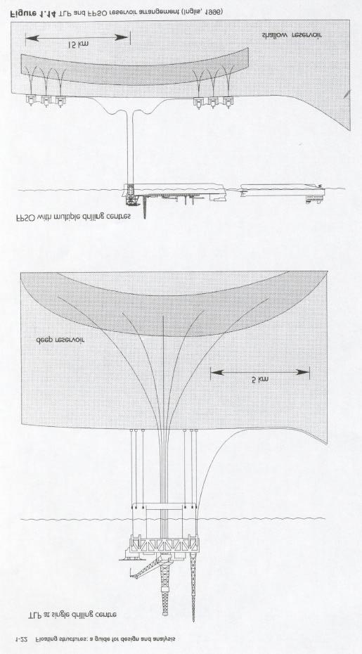
19 1.3.3 Field requirements that drive concept selection The production facilities must be matched to the field requirements so it is necessary to examine some of the characteristics that influence concept selection. The main factors are: production volumes, environment, water depth (influences fixed versus floating, mooring and riser systems selection), distance to shore or infrastructure (pipeline or tanker off loading), the number of drilling centres required to drain the reservoir, reservoir fluid, the well intervention (work-over) frequency, risk to personnel. The production volumes, how much oil and gas are to be produced, strongly influence concept selection. A small reservoir may be ideal as a sub-sea tieback but a large one may be impossible to produce in this way due to limited capacity on the host platform. A large field may justify an oil export pipeline, which will allow a wider choice of concepts as will be discussed later. Large volumes of gas will generally dictate large export risers which may be more easily achieved on a T LP or Compliant Tower than a FPSO. What is clear is that Floating Production Systems are no longer confined to small production rates and that 200,000 bbl/day of oil with up to 200 million scf/day of gas are feasible. Higher production rates will generally require larger deck areas and capacity. Environmental conditions: Offshore structures must often withstand an extremely harsh environment. In this book, the environmental conditions (wind, wave and current), the resulting loads and their effect on floating structures will be considered. Loads due to ice will not be considered but an overview of ice prone areas will be given. Earthquake loading may often be ignored as (except for the heave, pitch and roll modes of a T LP and more generally for riser and tether systems) the basic compliance of floating structures results in little influence from earthquake loading. West of Shetland Northern North Sea Gu lf of Mexico Philippines Brazil West Africa Table 1.2 Environmental conditions 100 Year Sig. Wave Height (metres) Wave Period (Seconds) Environmental conditions for some of the deep-water areas are shown in Table 1.2. Advances in design capability mean that environmental conditions are less of a feasibility issue but do impact concept select1on through the cost. For example, deep water TLP s may be feasible in both the mild environment of West Africa and the hostile environment West of Shetland but the amount of steel and hence cost of a TLP would be quite different, and the milder environment will permit other types of platform to be considered so possibly favouring different concepts in the two areas. Water depth has a strong and direct impact on technical feasibility and cost. The fixed offshore structure Bullwinkle is in a water depth of 412 m and it is unlikely that there will be any larger. The limit for a Gravity Base 18
20 Structure (GES) is probably somewhat less. Floating structures all have minimum water depth limits but as yet undetermined maximum water depth limits. Existing and planned facilities include Auger TLP (872 m); Mars TLP (894 in), Ursa TLP (1200 in); Petrobras XVII1 semi -submersible (910 in); Mensa sub-sea (1675 in). The increases in water depth for exploration drilling and production over time are shown in Figure This suggests that the water depth limit for production simply lags that for drilling by years. Alternatively there may be little point in drilling prospects which cannot be brought into production within years. Distance to shore or an oil terminal has a major impact on the most economical crude export option. A pipeline is generally the preferred solution but if the distance to shore is large, off shore loading to tankers is more cost effective. It is economics based on life-cycle cost that ultimately determines the choice between a pipeline or offshore loading system, and here capital cost, operating cost and tariffs must all be considered. In most situations in- field oil storage is required to make the offshore loading efficient and avoid repeated production shutdowns. In-field storage may be integral to the production facility (e.g. FPSO, Spar) or stand-alone (e.g. FSU- Floating Storage Unit). The offshore loading facilities may also be integral to the production facility (e.g. FPSO) or stand alone (e.g. OLS.Offshore Loading System). The strategy of retaining a shuttle tanker infield to provide temporary storage, possibly using twin-loading systems, looks increasing1y attractive and is threatening the traditional role of the FSU. The main oil export options, illustrated in Figure 1.13, are: production facility without storage + pipeline, production facility without storage + direct shuttle tanker loading,, production facility without storage + Floating Storage & Off-Loading Unit (FSU), production facility with integral storage plus stand alone Off-Loading System (e.g. Spar + OLS), production facility with integral storage & off-loading (e.g. FPSO). The storage capacity provided on an FPSO is a function of the number of shuttle tankers used, the shuttle tanker size, the maximum amount of estimated shuttle tanker waiting time due to weather conditions and distance to nearest port. 19
21 The FPSO may return to port for cargo discharge as does the 'SWOPS' vessel. This option is in general valid only for marginal fields with low production rates and a small number of risers. This solution is perhaps most suited for well testing and early production type of vessels producing through a single riser. 20
22 The other aspect of proximity to shore or other existing infrastructure is the potential for a sub-sea tie-back development. Here sub-sea wells are located in deep water and tied-back to a shallow platform via individual flowlines from separate satellite wells or through a single co-mingled export flowline from a sub-sea manifold. The tie-back distance record of Togi at 48 km was doubled to 109 km by the 1997 Mensa development. The number of drilling centres and the number of wells required at each centre to adequately drain the reservoir is dependent on the field architecture. Advances in extended reach drilling technology have increased the alonghole depth of wells to almost 10 km, with horizontal to vertical depth ratios of up to 3 being possible. However, in many situations it is still not possible to efficiently drain the reservoir from one drilling centre. This is often the case when the reservoir is relatively shallow and has a large area, see Figure Multiple drilling centres are certainly required where it is planned to have satellite fields tied back to a central production facility.if there are only a small number of drilling centres and frequent drilling or workover is required through the life of the platform then there is some advantage in having a platform with a drilling and work-over capability. Otherwise an additional vessel will be required for these purposes. Reservoir fluid parameters, production chemistry and hydraulics must all be considered in selecting the optimum development concept. This must encompass the implications of: CO2 H 2 S (naturally occurring as well as from reservoir souring), asphaltene deposition, wax deposition, scale precipitation, hydrate formation, sand production, slugging flow in multiphase flowlines, reservoir pressure and drive mechanisms. The parameters affect the well intervention (work over) frequency as well as the design of the production facilities. Well intervention may be necessary to maintain optimum performance due to mechanical failure, the effects of corrosion and wear or the need to open or close production from different levels. The risk to personnel will vary with the concept. There will be some variation in risk caused by the different hydrostatic, dynamic and structural behaviour of the different concepts but, for well designed platforms with: adequate reserves of intact and damaged stability, adequate ultimate and fatigue strength, and constructed from good toughness steel. these risks should be small. The variability in risk will be much more associated with: oil and gas import and export, the process system, the layout of the topside equipment, the position of the accommodation, collision with errant vessels (trading vessels, shuttle tanker, supply boat, safety boat), the provision of adequate evacuation systems (free fall lifeboats or other systems), preparations for inclement weather (riser/turret disconnect etc.). Clearly the platform concept affects these risks but they need to be considered in conjunction by the range of disciplines, not just the naval architects and structural engineers. 21
23 22
24 1.3.4 Performance requirements A floating structure for hydrocarbon drilling, production or export typically has the following performance require ments: sufficient work area, deck load capacity and perhaps storage capacity, acceptable response to environmental loads, adequate stability, strength to resist extreme conditions, durability to resist fatigue loading, may require a combined function (e.g. drilling and production), may be transportable. No one structure type can provide optimum performance with regard to each of the above requirements. Thus, any field development or exploration activity should identify the optimal structure type for the particular task from a number of classes of floating offshore structures. For example, excellent stability characteristics may lead to excessive motions in waves. In response to these conflicting requirements, the offshore industry has developed a wide variety of platforms Concept selection The development concepts identified in Section above must be matched to the field requirements discussed in Section to identify likely field development schemes. This has been done for deep water in Table 1.3 based on combinations of: distance to shore, number of drilling centres and well intervention frequency. Whilst there are certainly other factors that may influence concept selection in a particular situation, Table 1.3 appears to be a reasonable predictor of concepts selected in reality. The logic used in Table 1.3 is as follows. The concept selection is based primarily on an oil field with associated gas which may be exported, re-injected or possibly flared. For a gas field, possibly with associated liquids, different criteria will apply. When the distance to shore is short, pipeline export is assumed unless a FPSO is used since this already has an integral export system. Where the distance to shore is long, offshore loading is assumed. Where the well entry frequency is low, it is assw11ed that sub-sea wells will be the cheapest and only concepts with sub-sea wells are proposed for both single and multiple drilling centres. For single drilling centres and high well entry frequency, surface trees are preferred. These require TLP s, Compliant Towers or Spars. A semi-submersible with work-over capability is also a candidate. The combination of multiple drilling centres with wells that need frequent intervention, is accommodated in shallow water by using a well head jacket. In deep water this would require multiple TLP s or Compliant Towers which is not economically viable. No deep water field has yet been developed which combines multiple drilling centres and frequent well intervention but the currently favoured solution is a small unmanned TLP, or mini- TLP, which only supports the wells and provides a capability for drilling and work-over. The mini- TLP has no processing facilities as these are provided by another central facility such as a semi-submersible or FPSD moored close by. It is important to recognise that the mini- TLP is providing an alternative well system to sub-sea wells and flow lines and that the same production facility can be used in either case. Another important situation in deep water in which surface completed wells are potentially attractive is where the combination of extended reach drilling from one or more mini- TLP s is simply cheaper or technically more robust than sub-sea wells, flow-lines and risers. With the recent significant increases in the cost of deep water drilling 23
RIGID RISERS FOR TANKER FPSOs
 RIGID RISERS FOR TANKER FPSOs Stephen A. Hatton 2H Offshore Engineering Ltd. SUMMARY Recent development work on the subject of dynamic rigid (steel pipe) risers demonstrates that their scope of application
Deepwater Floating Production Systems An Overview
 Deepwater Floating Production Systems An Overview Introduction In addition to the mono hull, three floating structure designs Tension leg Platform (TLP), Semisubmersible (Semi), and Truss Spar have been
Offshore Oil and Gas Platforms for Deep Waters
 Offshore Oil and Gas Platforms for Deep Waters Atilla Incecik Department of Naval Architecture, Ocean and Marine Engineering University of Strathclyde, Glasgow, UK (atilla.incecik@strath.ac.uk) Summary
Learn more at
 Bottom Weighted Riser A Novel Design for Re-location and Disconnection Frank Lim and John McGrail 2H Offshore Engineering Ltd. Woking, Surrey, United Kingdom ABSTRACT Flexible pipe risers have limitations
A Novel Platform for Drilling in Harsh High-Latitude Environments.
 AADE-7-NTCE-73 A Novel Platform for Drilling in Harsh High-Latitude Environments. Brian Roberts, Technip; Chunqun Ji, Technip; Jim O Sullivan, Technip and Terje Eilertsen, Technip. Copyright 27, AADE This
LNG TANDEM OFFLOADING A KEY ENABLING TECHNOLOGY TO MAKE LNG PRODUCTION OFFSHORE HAPPEN
 LNG TANDEM OFFLOADING A KEY ENABLING TECHNOLOGY TO MAKE LNG PRODUCTION OFFSHORE HAPPEN Fabrice Dumortier 1, Jean-Pierre Queau 1, Jean-Robert Fournier 2 1. SBM Offshore 2. SBM Offshore Keywords: 1. LNG;
Innovative and Robust Design. With Full Extension of Offshore Engineering and Design Experiences.
 Innovative and Robust Design by VL Offshore With Full Extension of Offshore Engineering and Design Experiences www.vloffshore.com Y Wind Semi Designed by VL Offshore The Y Wind Semi platform (foundation)
From the Wellhead to the Tanker Offshore Production Systems. 28/03/2014 Instituto Superior Técnico
 From the Wellhead to the Tanker Offshore Production Systems Index Offshore Installations Subsea Systems Field overview Christmas Trees Manifolds Templates Mid-Water Arches Topsides FPSOs The Oil Production
The Benefits Of Composite Materials In Deepwater Riser Applications. 26 th March 2015 Hassan Saleh Senior Engineer 2H Offshore Engineering Ltd
 The Benefits Of Composite Materials In Deepwater Riser Applications 26 th March 2015 Hassan Saleh Senior Engineer 2H Offshore Engineering Ltd Composite Benefits and Challenges Composite Materials offer
TLP Minimum tendon tension design and tendon down-stroke investigation
 Published by International Association of Ocean Engineers Journal of Offshore Engineering and Technology Available online at www.iaoejoet.org TLP Minimum tendon tension design and tendon down-stroke investigation
Low Cost Flexible Production System for Remote Ultra-Deepwater Gulf of Mexico Field Development
 Low Cost Flexible Production System for Remote Ultra-Deepwater Gulf of Mexico Field Development 10121-4404-03 Jelena Vidic-Perunovic, Doris, Inc. Lars Ødeskaug, Sevan Marine ASA RPSEA Ultra-Deepwater Technology
A NEW DEEPWATER TANKER LOADING SYSTEM FOR WEST AFRICA
 A NEW DEEPWATER TANKER LOADING SYSTEM FOR WEST AFRICA Arun S. Duggal, FMC SOFEC Floating Systems, USA Charles O. Etheridge, FMC SOFEC Floating Systems, USA James Mattinson, FMC SOFEC Floating Systems,
The Impact of Composites on Future Deepwater Riser Configurations
 The Impact of Composites on Future Deepwater Riser Configurations Thomas Brown 2H Offshore Engineering Ltd NH GRAND HOTEL KRASNAPOLSKY AMSTERDAM 3-5 APRIL 2017 Deepwater Riser Technology Today s deepwater
Learn more at
 IBP1833_06 COST EFFICIENT ARTIFICIAL BUOYANT SEABED DRILLING SOLUTION Dan Moutrey 1, Frank Lim 2 Copyright 2006, Instituto Brasileiro de Petróleo e Gás - IBP This Technical Paper was prepared for presentation
FPSO MOORING CONFIGURATION BASED ON MALAYSIA S ENVIRONMENTAL CRITERIA
 FPSO MOORING CONFIGURATION BASED ON MALAYSIA S ENVIRONMENTAL CRITERIA Mazlan Muslim and Md Salim Kamil Marine and Design Technology Section, University Kuala Lumpur MIMET, Lumut, Perak, Malaysia E-Mail
TARPON A Minimal Facilities Platform
 TARPON A Minimal Facilities Platform Contents Introduction TARPON Description TARPON Features TARPON Benefits TARPON Proofs TARPON Typical Installation Options Design Codes & Certification Novel Application
Fundamentals Of Petroleum Engineering PRODUCTION
 Fundamentals Of Petroleum Engineering PRODUCTION Mohd Fauzi Hamid Wan Rosli Wan Sulaiman Department of Petroleum Engineering Faculty of Petroleum & Renewable Engineering Universiti Technologi Malaysia
EXPERIMENTAL INVESTIGATIONS OF BARGE FLOATER WITH MOONPOOL FOR 5 MW WIND TURBINE
 EXPERIMENTAL INVESTIGATIONS OF BARGE FLOATER WITH MOONPOOL FOR 5 MW WIND TURBINE 1 MR. G.VIJAYA KUMAR, 2 DR. R. PANNEER SELVAM 1 M.S. Research Scholar, Department of Ocean Engineering, IIT Madras, Chennai,
A New Thermoplastic Composite Riser for Deepwater Application
 A New Thermoplastic Composite Riser for Deepwater Application Martin van Onna, Managing Director Airborne Composite Tubulars Patrick O Brien, Group Director Strategic Business & Marketing, Wood Group Kenny
Development of Self-Installing Deepwater Spar. Ashit Jadav February 2017
 Development of Self-Installing Deepwater Spar Ashit Jadav February 2017 Contents Introduction & Background ACE Spar breakdown Installation Sequence Main particulars, Hull design and Weight control Stability
NOBLE REV 02 FPSO MOORING SYSTEM INTEGRITY STUDY
 DENTON INTEGRITY STUDY APPENDIX C INCIDENT REPORTS Incident One FPSO Questionnaire Failure of gripper used to rotate turret Several months after installation This FPSO has an internal partially rotating
Design Challenges & Solutions for Large Diameter Export Risers
 Design Challenges & Solutions for Large Diameter Export Risers Elizabeth Tellier, Hugh Howells & Mark Cerkovnik 2H Offshore Engineering AOG 2011 Agenda WA export riser design challenges Development options
Dynamic Positioning: Method for Disaster Prevention and Risk Management
 Available online at www.sciencedirect.com ScienceDirect Procedia Earth and Planetary Science 11 ( 2015 ) 216 223 Global Challenges, Policy Framework & Sustainable Development for Mining of Mineral and
Top Tensioned Riser Challenges and Solutions for Dry Tree Facilities in Asia Pacific
 June 2011 Top Tensioned Riser Challenges and Solutions for Dry Tree Facilities in Asia Pacific Daniel Brooker, MCS Kenny Presentation Agenda 1. Objectives 2. Top Tensioned Riser (TTR) Selection Drivers
The SDS Skip. Subsea Deployment Systems Ltd.
 The SDS Skip SUBSEA SKIP An alternative to enhance the recovery of structures, spool pieces, mattresses etc. during decommissioning work Can be used to transport complex structures or spool pieces to field
EFFECT OF DIFFERENT MOORING SYSTEMS ON HYDRODYNAMIC ANALYSIS OF AN OFFSHORE WIND TURBINE
 EFFECT OF DIFFERENT MOORING SYSTEMS ON HYDRODYNAMIC ANALYSIS OF AN OFFSHORE WIND TURBINE Sabri ALKAN 1, Ayhan Mentes 2, Ismail H. Helvacioglu 2, Nagihan Turkoglu 2 1 Department of Mechanical Engineering,
Computer Simulation Helps Improve Vertical Column Induced Gas Flotation (IGF) System
 System") JOURNAL ARTICLES BY FLUENT SOFTWARE USERS JA187 Computer Simulation Helps Improve Vertical Column Induced Gas Flotation (IGF) System Computer simulation has helped NATCO engineers make dramatic improvements
JOURNAL ARTICLES BY FLUENT SOFTWARE USERS JA187 Computer Simulation Helps Improve Vertical Column Induced Gas Flotation (IGF) System Computer simulation has helped NATCO engineers make dramatic improvements
APPENDIX D. Assessment of Ship Impact Frequencies
 APPENDIX D Assessment of Ship Impact Frequencies WHITE ROSE DEVELOPMENT APPLICATION APPENDIX D ASSESSMENT OF SHIP IMPACT FREQUENCIES SUBMITTED BY: HUSKY OIL OPERATIONS LIMITED AS OPERATOR SUITE 801, SCOTIA
Challenges in Ship Design to Maintain Thrusters inside Ship
 DYNAMIC POSITIONING CONFERENCE October 9-10, 2012 Thrusters Challenges in Ship Design to Maintain Thrusters inside Ship Tom Nylund and Timo Rintala Beacon Finland 1 DP Conference - Challenges in Ship Design
RAMSTM. 360 Riser and Anchor-Chain Integrity Monitoring for FPSOs
 RAMS 360 Riser and Anchor-Chain Integrity Monitoring for FPSOs Introduction to RAMS Tritech s RAMS is a 360 anchor-chain and riser integrity monitoring system for Floating Production Storage and Offloading
Feasibility of Steel Lazy Wave Risers in the North Sea
 NH GRAND HOTEL KRASNAPOLSKY AMSTERDAM 3-5 APRIL 2017 Feasibility of Steel Lazy Wave Risers in the North Sea Rohit Shankaran 2H Offshore Engineering Ltd. Agenda Risers in deepwater North Sea Are steel catenary
Learn more at
 vs. for Deepwater Applications Technical Appraisal John McGrail and Frank Lim 2H Offshore Engineering Limited Woking, UK ABSTRACT This paper provides a technical appraisal of the use of Single Line Offset
Ocean Engineering Prof. Dr. Srinivasan Chandrasekaran Department of Ocean Engineering Indian Institute of Technology, Madras
 Ocean Engineering Prof. Dr. Srinivasan Chandrasekaran Department of Ocean Engineering Indian Institute of Technology, Madras Module - 1 Lecture - 3 Compliant type offshore structures -1 Welcome to the
TECHNICAL BENEFITS OF CJS / RAISE HSP. Technical Advantages
 TECHNICAL BENEFITS OF CJS / RAISE HSP Technical Advantages The HSP is designed for low- to mid- volume applications at flow rates of 1 cubic meter to 30 c. m per day. The benefits are in the details. The
Time-domain Nonlinear Coupled Analyses Covering Typical Mooring and Riser Configurations for FPSOs
 PAU, FRANCE 5-7 APRIL 2016 Time-domain Nonlinear Coupled Analyses Covering Typical Mooring and Riser Configurations for FPSOs Author: Fan Joe Zhang Presenter: Styrk Finne DNV GL - Software Contents Typical
Pigging as a Flow Assurance Solution Avoiding Slug Catcher Overflow
 Pigging as a Flow Assurance Solution Avoiding Slug Catcher Overflow Aidan O'Donoghue, Pipeline Research Limited, Glasgow, UK This paper sets out to provide an initial method of assessing the bypass requirements
REVISITING GLOBAL RESPONSE OF FPSOS IN SHALLOW WATER AND THE RISER ANALYSIS REQUIREMENTS
 REVISITING GLOBAL RESPONSE OF FPSOS IN SHALLOW WATER AND THE RISER ANALYSIS REQUIREMENTS AMIR H. IZADPARAST SENIOR RESEARCH ENGINEER, HYDRODYNAMICS AND MOORING TECHNOLOGY, SOFEC JIAXING CHEN RESEARCH ENGINEER,
Caltec. The world leader in Surface Jet Pump (SJP) and compact separation systems for upstream oil and gas production enhancement
 and compact separation systems for upstream oil and gas production enhancement") Caltec brings simple passive technology that enables oil and gas operators to harness the kinetic energy of the production process to enhance their production, extending economic field life and reducing
Caltec brings simple passive technology that enables oil and gas operators to harness the kinetic energy of the production process to enhance their production, extending economic field life and reducing
Application of CFD for Improved Vertical Column Induced Gas Flotation (IGF) System Development
 System Development") Application of CFD for Improved Vertical Column Induced Gas Flotation (IGF) System Development Chang-Ming Lee and Ted Frankiewicz NATCO Group, Inc., 2950 North Loop West, Suite 750, Houston, TX 77092 Prepared
Application of CFD for Improved Vertical Column Induced Gas Flotation (IGF) System Development Chang-Ming Lee and Ted Frankiewicz NATCO Group, Inc., 2950 North Loop West, Suite 750, Houston, TX 77092 Prepared
Dynamics of Ocean Structures Prof. Dr Srinivasan Chandrasekaran Department of Ocean Engineering Indian Institute of Technology, Madras
 Dynamics of Ocean Structures Prof. Dr Srinivasan Chandrasekaran Department of Ocean Engineering Indian Institute of Technology, Madras Module - 1 Lecture - 4 Types of Compliant Towers So, we will continue
WIND TURBINE SHUTTLE HUISMAN PRODUCT BROCHURE
 WIND TURBINE SHUTTLE HUISMAN PRODUCT BROCHURE WIND TURBINE HUTTLE TABLE OF CONTENTS 01 DESCRIPTION 03 1.1 Vessel General 03 1. Purpose of the Vessel 0 1.3 High Workability 0 1. Installation Scenarios 05
RPSEA UDW Forum June 22 & 23, Secure Energy for America
 RPSEA UDW Forum June 22 & 23, 2010 Secure Energy for America PROJECT TEAM RPSEA Operator Advisory Committee Anadarko Chevron Shell ConocoPhillips Subcontractors IntecSea NOV CTES General Marine Contractors
GUIDELINES FOR SURVEY OF OIL FLOATING STORAGE VESSELS FIXED AT ANCHORAGE
 GUIDANCE NOTES GD03-2017 CHINA CLASSIFICATION SOCIETY GUIDELINES FOR SURVEY OF OIL FLOATING STORAGE VESSELS FIXED AT ANCHORAGE 2017 Effective from 1 March 2017 BEIJING Chapter 1 GENERAL 1.1 Application
Minimal Structures for Marginal Nova Scotia Developments
 Minimal Structures for Marginal Nova Scotia Developments May 12, 2009 Cameron Dunn Martec is a member of the Lloyd s Register Group 1 2 Minimal Structures Project NSDOE working to make the Nova Scotia
Steel Lazy Wave Risers A Step Change in Riser Technology for the NWS
 Steel Lazy Wave Risers A Step Change in Riser Technology for the NWS Tze King Lim, Dhyan Deka, Elizabeth Tellier, Hugh Howells AOG 2018, Perth 15 th March 2018 Agenda Lazy wave risers an enabling technology
Pipeline Flooding, Dewatering and Venting Dr Aidan O'Donoghue, Pipeline Research Limited, Glasgow, Scotland
 Pipeline Flooding, Dewatering and Venting Dr Aidan O'Donoghue, Pipeline Research Limited, Glasgow, Scotland Abstract Flooding, cleaning, gauging, dewatering and venting of offshore oil and gas pipelines
BRINGING A NEW DIMENSION TO PIPELINE PIGGING. By: David Aitken, Aubin Group, UK
 BRINGING A NEW DIMENSION TO PIPELINE PIGGING By: David Aitken, Aubin Group, UK The importance of keeping pipework clear of restrictions and debris to allow maximum flow conditions cannot be emphasised
Re-usable Riser and Flowline System for Deep Water Application. C. DIEUMEGARD SUBSEA ASIA - 11 th June 2008
 Re-usable Riser and Flowline System for Deep Water Application C. DIEUMEGARD SUBSEA ASIA - 11 th June 2008 Table of Contents Flexible Pipe Technology Deep Water Challenges for Riser, Flowline and Umbilical
Risers for Deepwater FPSO s
 Risers for Deepwater FPSO s John Bob-Manuel Senior Engineer 2H Offshore Engineering Ltd. March 2013 Agenda 2H overview Challenges of Deepwater Operations Freestanding Riser Overview Riser Configurations
Development of Accidental Collapse Limit State Criteria for Offshore Structures
 Risk Acceptance and Risk Communication Stanford, March 26-27, 2007 Development of Accidental Collapse Limit State Criteria for Offshore Structures by Torgeir Moan Norwegian University of Science and Technology
Permanent buoyancy systems. matrix composites & engineering
 Permanent buoyancy systems matrix composites & engineering Contents Permanent buoyancy systems 3 Materials qualification testing 4 Distributed buoyancy clamping system 5 Buoyancy building block system
$ Millions. The PC Semi: A Low Motion Semisubmersible Capable of a Wet or Dry Tree Configuration. Semi Hull CAPEX Differentials. Topsides.
 The : A Low Motion Semisubmersible Capable of a Wet or Dry Tree Configuration In our ever changing and uncertain market conditions, it is extremely important to ensure capital investments are successful
Wind Turbine Shuttle. Ferdinand van Heerd
 Wind Turbine Shuttle Ferdinand van Heerd Contents Introduction Concept Resistance Seakeeping Vessel motion compensation system Hoisting motion compensation system Landing the wind turbine Workability Efficiency
PRESTIGE OIL RECOVERY FROM THE SUNKEN PART OF THE WRECK Massimo Fontolan, Sonsub Ltd., Robin Galletti, SATE srl. Introduction
 PRESTIGE OIL RECOVERY FROM THE SUNKEN PART OF THE WRECK Massimo Fontolan, Sonsub Ltd., Robin Galletti, SATE srl. Introduction This lecture deals with the equipment developed and the experience gained during
ROV Development ROV Function. ROV Crew Navigation IRATECH SUB SYSTEMS 2010
 IR AT EC H SU B SY ST EM S 20 10 Remotely Operated Vehicle ROV INTRODUCTORY 2008 2008 1 KEY POINTS ROV Introductory ROV Development ROV Function Types of ROV ROV Crew Navigation ROV Components 2 ROV Development
ANNEX 2 RESOLUTION MEPC.124(53) Adopted on 22 July 2005 GUIDELINES FOR BALLAST WATER EXCHANGE (G6) THE MARINE ENVIRONMENT PROTECTION COMMITTEE,
 Adopted on 22 July 2005 GUIDELINES FOR BALLAST WATER EXCHANGE (G6) THE MARINE ENVIRONMENT PROTECTION COMMITTEE,") Page 1 RESOLUTION MEPC.124(53) Adopted on 22 July 2005 GUIDELINES FOR BALLAST WATER EXCHANGE (G6) THE MARINE ENVIRONMENT PROTECTION COMMITTEE, RECALLING Article 38(a) of the Convention on the International
Page 1 RESOLUTION MEPC.124(53) Adopted on 22 July 2005 GUIDELINES FOR BALLAST WATER EXCHANGE (G6) THE MARINE ENVIRONMENT PROTECTION COMMITTEE, RECALLING Article 38(a) of the Convention on the International
Offshore Losses Case Studies
 Offshore Losses Case Studies David Brown BSc(Eng), PhD, CEng, FRINA, FSUT, SNAME, FIMechE Engineering Director BPP Technical Services OPERA Lessons from Disaster Author s Experience Experience Professional
The Time Has Come For Coiled Rod. Reprinted from Well Servicing magazine
 The Time Has Come For Coiled Rod Reprinted from Well Servicing magazine The development of flush-by well service units and stand-alone coiled rod injector head technology has helped grow the coiled rod
PASSENGER SHIPS Guidelines for preparation of Hull Structural Surveys
 (Feb 2010) PASSENGER SHIPS Guidelines for preparation of Hull Structural Surveys Contents 1 Introduction 2 Preparations for Survey 2.1 General 2.2 Conditions for survey 2.3 Access to structures 2.4 Survey
OFFICIAL MESSAGE CIRCULAR
 OFFICIAL MESSAGE CIRCULAR From: NI/ DP Department Number: 010/2012 Date: 20.12.2012 Number of pages: 7 To: Dynamic Positioning Accredited Training Centres Cc: DPTEG members Referent to: Aims and Objectives
Learn more at
 Full scale model tests of a steel catenary riser C. Bridge 1, H. Howells 1, N. Toy 2, G. Parke 2, R. Woods 2 1 2H Offshore Engineering Ltd, Woking, Surrey, UK 2 School of Engineering, University of Surrey,
Chapter 2 Hydrostatics and Control
 Chapter 2 Hydrostatics and Control Abstract A submarine must conform to Archimedes Principle, which states that a body immersed in a fluid has an upward force on it (buoyancy) equal to the weight of the
Numerical modelling of disconnectable turret mooring systems
 Numerical modelling of disconnectable turret mooring systems A. Duggal, S. Ryu & O. De Andrade Research & Development Department, SOFEC Inc., USA. Abstract Floating, Production, Storage, and Offloading
A Generic Model To Assess Major Incident Frequencies For Offshore Assets
 A Generic Model To Assess Major Incident Frequencies For Offshore Assets Richard Emery, MMI Engineering Ltd, The Brew House, Wilderspool Park, Greenall s Avenue, Warrington, WA4 6HL. Quantitative risk
DEEP WATER DRILLING RISER TECHNOLOGY, VIV & FATIGUE MANAGEMENT
 DEEP WATER DRILLING RISER TECHNOLOGY, VIV & FATIGUE MANAGEMENT by Dr Hugh Howells 2H Offshore Engineering Limited Drilling Engineering Association (Europe), 4th Quarter Meeting, Paris 1998 SCOPE OF PRESENTATION
INTRODUCING THE PILLAR BOAT! U.S. Patent No. 9,623,935 ABSTRACT
 INTRODUCING THE PILLAR BOAT! U.S. Patent No. 9,623,935 ABSTRACT The need to conduct motion sensitive operations at sea is increasing in the fields of space launch and recovery, oil exploration, aquaculture,
Proceedings of the International Conference on Emerging Trends in Engineering and Management (ICETEM14) 30-31,December, 2014, Ernakulam, India
 30-31,December, 2014, Ernakulam, India") INTERNATIONAL JOURNAL OF DESIGN AND MANUFACTURING TECHNOLOGY (IJDMT) Proceedings of the International Conference on Emerging Trends in Engineering and Management (ICETEM14) ISSN 0976 6995 (Print) ISSN
INTERNATIONAL JOURNAL OF DESIGN AND MANUFACTURING TECHNOLOGY (IJDMT) Proceedings of the International Conference on Emerging Trends in Engineering and Management (ICETEM14) ISSN 0976 6995 (Print) ISSN
Offshore Stabilization Pontoon for a heavy lift vessel Concept design & workability
 Offshore Stabilization Pontoon for a heavy lift vessel A.M. ten Klooster Delft University of Technology OFFSHORE STABILIZATION PONTOON FOR A HEAVY LIFT VESSEL CONCEPT DESIGN & WORKABILITY by A.M. ten Klooster
Semi-Submersible Offshore Platform Simulation Using ANSA & META
 Semi-Submersible Offshore Platform Simulation Using ANSA & META Offshore platforms are large structures designed to withstand extreme weather conditions and have a lifespan of at least 40 years. Million
Offshore Pipeline Installation SEABED INTERVENTION THE GAME-CHANGING EFFECT DISRUPTION TO HEAVY LIFTING HOW DO YOU MAKE THE SEABED?
 OSI 2016 VOLUME 9 ISSUE 1 OSI VOL. 9 ISSUE 1 2016 i n d u s t r y DECOMMISSIONING THE GAME-CHANGING EFFECT DISRUPTION TO HEAVY LIFTING OFFSHORE-INDUSTRY.EU SEABED INTERVENTION HOW DO YOU MAKE THE SEABED?
SLOP RECEPTION AND PROCESSING FACILITIES
 RULES FOR CLASSIFICATION OF SHIPS NEWBUILDINGS SPECIAL SERVICE AND TYPE ADDITIONAL CLASS PART 5 CHAPTER 8 SLOP RECEPTION AND PROCESSING FACILITIES JANUARY 2011 CONTENTS PAGE Sec. 1 General Requirements...
DP Ice Model Test of Arctic Drillship
 Author s Name Name of the Paper Session DYNAMIC POSITIONING CONFERENCE October 11-12, 211 ICE TESTING SESSION DP Ice Model Test of Arctic Drillship Torbjørn Hals Kongsberg Maritime, Kongsberg, Norway Fredrik
ANCHORING REQUIREMENTS FOR LARGE CONTAINER SHIPS
 ANCHORING REQUIREMENTS FOR LARGE CONTAINER SHIPS 1 INTRODUCTION 1.1 Background Some modern container ships are larger than most of the existing fleet, whose experience has been used as the basis of classification
Proceedings of the ASME th International Conference on Ocean, Offshore and Arctic Engineering OMAE2011
 Proceedings of the ASME 2011 30th International Conference on Ocean, Offshore and Arctic Engineering OMAE2011 June 19-24, 2011, Rotterdam, The Netherlands Proceedings of the ASME 2011 30th International
Risks Associated with Caissons on Ageing Offshore Facilities
 Risks Associated with Caissons on Ageing Offshore Facilities D. Michael Johnson, DNV GL, Peter Joyce, BG Group, Sumeet Pabby, BG Group, Innes Lawtie, BG Group. Neil Arthur, BG Group, Paul Murray, DNV GL.
OLGA. The Dynamic Three Phase Flow Simulator. Input. Output. Mass transfer Momentum transfer Energy transfer. 9 Conservation equations
 서유택 Flow Assurance The Dynamic Three Phase Flow Simulator 9 Conservation equations Mass (5) Momentum (3) Energy (1) Mass transfer Momentum transfer Energy transfer Input Boundary and initial conditions
Subsea Safety Systems
 Subsea Safety Systems The ELSA-HP has been developed to service the high pressure horizontal tree completion and intervention market. With systems designed and qualified up to 15,000 psi, 250 degf and
Simplicity in VRU by using a Beam Gas Compressor
 Simplicity in VRU by using a Beam Gas Compressor By Charlie D. McCoy and Mark Lancaster Abstract: Vapor Recovery Units are often expensive, complicated to operate and unable to deal with High H2S and liquids.
Drilling Efficiency Utilizing Coriolis Flow Technology
 Session 12: Drilling Efficiency Utilizing Coriolis Flow Technology Clement Cabanayan Emerson Process Management Abstract Continuous, accurate and reliable measurement of drilling fluid volumes and densities
International Journal of Scientific & Engineering Research, Volume 7, Issue 10, October ISSN
 International Journal of Scientific & Engineering Research, Volume 7, Issue 10, October-2016 172 DYNAMIC ANALYSIS OF MINI TENSION LEG PLATFORMS UNDER RANDOM WAVES Shibin P Shaji, Dr. Jayalekshmi R. Abstract
FIXED VERSUS DISCONNECTABLE TURRET SYSTEM FOR F(P)SO S FOR GULF OF MEXICO
SO S FOR GULF OF MEXICO") FIXED VERSUS DISCONNECTABLE TURRET SYSTEM FOR F(P)SO S FOR GULF OF MEXICO London T. England Jr. FMC SOFEC Floating Systems, USA ABSTRACT With the anticipated development of a large number of deepwater
FIXED VERSUS DISCONNECTABLE TURRET SYSTEM FOR F(P)SO S FOR GULF OF MEXICO London T. England Jr. FMC SOFEC Floating Systems, USA ABSTRACT With the anticipated development of a large number of deepwater
Fully Submersible Heavy Lift Vessel
 Fully Submersible Heavy Lift Vessel Arnbjorn Joensen Aberdeen Maritime Branch (28th January 2015) PRESENTATION Introduction to the Subsea Deployment Vessel Installation method Tank test video Potential
DIFFERENT SOLUTIONS TO INSPECT PLATFORM RISERS. By R van Agthoven and H Quakkelsteijn, ApplusRTD, Rotterdam, The Netherlands
 DIFFERENT SOLUTIONS TO INSPECT PLATFORM RISERS By R van Agthoven and H Quakkelsteijn, ApplusRTD, Rotterdam, The Netherlands SUMMARY The need for the inspection of pipelines and risers is growing, as the
Spread Moored or Turret Moored FPSO s for Deepwater Field Developments
 Spread Moored or Turret Moored FPSO s for Deepwater Field Developments G. Boyd Howell, FMC Technologies Floating Systems, USA Arun S. Duggal, FMC Technologies Floating Systems, USA Caspar Heyl, FMC Technologies
An Ocean of Possibility
 An Ocean of Possibility SPM Offloading Buoy CALM Buoy Orwell Offshore s Catenary Anchor Leg Mooring (CALM) Buoy offers a reliable state-of-the-art solution for loading and offloading crude oil, refined
OFFSHORE. Trasfor OFFSHORE
 OFFSHORE Trasfor OFFSHORE 2 Trasfor I Offshore Introduction Trasfor s transformers for offshore applications ensure the highest performance level of reliability in any working condition. More than 40 skilled
White Paper. Electrical control valve actuators on oil and gas production separators
 White Paper Electrical control valve actuators on oil and gas production separators Electrical control valve actuators on oil and gas production separators White Paper 18 th August 2014 Electrical control
HiLoad, Introducing DP to Standard Tankers
 DYNAMIC POSITIONING CONFERENCE September 16-17, 2003 FPSOs and Shuttle Tankers HiLoad, Introducing DP to Standard Tankers Bjørn Egil Gustavsen Remora Technology (Houston) Table of contents 1 Abstract...2
Gas Injection for Hydrodynamic Slug Control
 Proceedings of the IFAC Workshop on Automatic Control in Offshore Oil and Gas Production, Norwegian University of Science and Technology, Trondheim, Norway, May 3 - June, ThB.4 Gas Injection for Hydrodynamic
Best Practice RBI Technology Process by SVT-PP SIMTECH
 Best Practice RBI Technology Process by SVT-PP SIMTECH We define the best practice in RBI as a proactive technology process which is used to formally and reliably optimise the inspection efforts for each
VESSEL DESIGNS HUISMAN PRODUCT BROCHURE
 VESSEL DESIGNS HUISMAN PRODUCT BROCHURE VESSEL ESIGNS TABLE OF CONTENTS 01 GENERAL 03 1.1 Introduction 03 1.2 Development 03 02 DRILL SHIPS 06 2.1 HuisDrill 12000 06 03 MOBILE OFFSHORE DRILLING UNITS 07
2 FUSION FITTINGS FOR USE WITH POLYETHYLENE PRESSURE PIPES DESIGN FOR DYNAMIC STRESSES
 Industry Guidelines Part 2 FUSION FITTINGS FOR USE WITH POLYETHYLENE PRESSURE PIPES DESIGN FOR DYNAMIC STRESSES ISSUE 5.1 Ref: POP10B 15 MAR 2010 Disclaimer In formulating this guideline PIPA has relied
A STUDY OF THE LOSSES AND INTERACTIONS BETWEEN ONE OR MORE BOW THRUSTERS AND A CATAMARAN HULL
 A STUDY OF THE LOSSES AND INTERACTIONS BETWEEN ONE OR MORE BOW THRUSTERS AND A CATAMARAN HULL L Boddy and T Clarke, Austal Ships, Australia SUMMARY CFD analysis has been conducted on a 100m catamaran hull
New Innovative Anchor Solution for Deepwater Mooring Gravity Intalled Anchors Reduce Time and Costs of Marine Operations Jon Tore Lieng CTO
 New Innovative Anchor Solution for Deepwater Mooring Gravity Intalled Anchors Reduce Time and Costs of Marine Operations Jon Tore Lieng CTO Wokshop on Deepwater Subsea TieBack Damai Puri Resort & Spa,
Completion Workover Riser System. Enabling efficient operations by reducing interface complexities and minimizes operational risk
 Completion Workover Riser System Enabling efficient operations by reducing interface complexities and minimizes operational risk Well integrity with fatigue management were key drivers for our system design
Operations. On The Use of Safety Moorings in DP Operations
 Return to Session Directory DYNAMIC POSITIONING CONFERENCE October 7-8, 28 Operations On The Use of Safety Moorings in DP Operations Nils Albert Jenssen Kongsberg Maritime, (Kongsberg Norway) Abstract
STATION KEEPING EXTENSIVE MODEL TESTING OF A DRY-TREE SPREAD-MOORED BARGE IN BRAZILLIAN WATERS
 STATION KEEPING EXTENSIVE MODEL TESTING OF A DRY-TREE SPREAD-MOORED BARGE IN BRAZILLIAN WATERS Arjan Voogt (MARIN) and Mamoun Naciri (SBM) Deep Offshore Technology XIV (DOT-2002) ABSTRACT This paper describes
FPSO Riser Solutions for Harsh environments
 FPSO Riser Solutions for Harsh environments Hanh Ha and Hugh Howells AOG Perth, March 2015 Overview Design challenges Flexibles Configurations and response Mild Environment Riser Harsh Environment Riser
17J Third Edition, January 2008 Specification for Unbonded Flexible Pipe
 API Specification 17J Third Edition, January 2008 National Adoption of ISO 13628:2006(Identical) Petroleum and natural gas industries Design and operation of subsea production systems Part 2: Unbonded
Planning of Drilling Operations in Extreme Ocean Currents
 DYNAMIC POSITIONING CONFERENCE October 11-12, 2016 OPERATIONS Planning of Drilling Operations in Extreme Ocean Currents Luca Pivano - Marine Cybernetics/DNV GL Kristopher Eide - Marine Cybernetics/DNV