|
|
|
- Asher Johnson
- 5 years ago
- Views:
Transcription
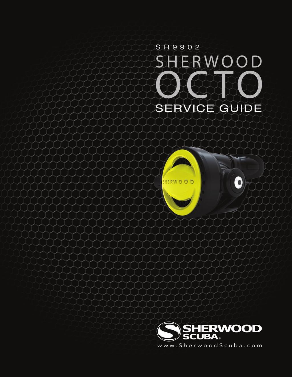
1
2 INTRODUCTION The instructions set forth in this document are intended to guide the experienced scuba equipment repair technician through the standard service procedure for this Sherwood regulator. It is assumed that the technician possesses basic scuba equipment repair training, proper tools and the skill necessary to perform the service. If you have not received regulator service training provided by Sherwood Scuba specifically for this equipment, do not attempt to perform the service described in this document. Service parts for Sherwood equipment are sold only to Authorized Sherwood Dealers. Before attempting to perform service read this manual in its entirety. There are warnings and cautions contained in the manual that may affect your safety or the safety of the regulator user. If you are uncertain as to whether you are qualified to perform this service contact your regional Sherwood Scuba Distributor for technical assistance. USE OF WARNINGS, CAUTIONS AND NOTES!! WARNING: CAUTION: NOTE: Indicates a potentially hazardous condition or situation which, if not avoided, may result in serious injury or death. Indicates a potentially hazardous condition or situation which, if not avoided, may result in minor injury. It may also be used to alert against unsafe practices. Indicates an important point or reminder. WHEN TO SERVICE This Sherwood regulator should be inspected for service at least annually. In most cases a simple inspection, and if needed, minimal adjustment not requiring the replacement of parts will be sufficient for continued use. Guidelines for the Annual Inspection are included in this manual. Sherwood regulators are designed and tested to perform acceptably under typical recreational diving conditions up to 300 hours of use. If the regulator has been subjected to more than 300 hours of use or it has not received the benefit of careful post-dive cleaning and storage in a clean environment, a standard service overhaul is required. In any case the Sherwood regulator described in this manual should receive a standard service overhaul at least every two years to maintain optimal performance. The standard service overhaul includes disassembly, cleaning, inspection, replacement of seals, lubrication, reassembly and adjustments. Sherwood Scuba offers a standard service kit that contains the parts recommended to be replaced in connection with the standard service overhaul. 2
3 ANNUAL INSPECTION GUIDELINES 1. Visually inspect the first and second stage for signs of damage or deterioration. Mouthpieces with tears or other damage should be replaced. 2. Retract hose protectors and inspect the hose over its entire length for signs of damage including blisters, deep cuts or separation at the crimped fittings. If these signs are present the hose must be replaced and standard service overhaul is recommended. 3. Insert a soft probe through the exit port of the exhaust cover and lift the Exhaust Valve to inspect it for cuts, tears or contaminated surfaces. Perform this examination from both sides of the Exhaust Cover to observe the entire perimeter of the Exhaust Valve. If damage to the Exhaust Valve is found a complete overhaul is recommended. If the Exhaust Valve or the sealing surfaces on the Housing are contaminated with debris, the Exhaust Cover must be removed and the surfaces must be cleaned. Instructions for removing and replacing the Exhaust Cover appear in the Second Stage Service Guide. As a final check of the Exhaust Valve apply a moderate suction (approximately minus 5 inches of water, moderate inhalation effort) to the second stage mouthpiece with the air supply closed and the second stage purged. If leakage is detected a complete overhaul is recommended. 4. Inspect the first stage filter for evidence of contamination. Discolored filters indicate previous contact with contaminated air. If evidence of contamination is present it is recommended that a standard service overhaul be performed. In addition you should advise the customer that the regulator has been exposed to contamination and that previously used air cylinders used should be inspected. 5. Install an intermediate pressure gauge into one of the available LP ports. 6. Pressurize the regulator to approximately 500 psi and inspect for leakage. Note intermediate pressure. It should not be greater than 150 psi. If no leakage is detected increase inlet pressure to 3000 psi. Again check intermediate pressure. It should not exceed 150 psi. If intermediate pressure is out of range 140 ± 10 psi or leakage is present a standard service overhaul is recommended. 7. Test the purge function. If there is not a strong surge of air, a standard overhaul is recommended. 8. Gently submerge the entire regulator and look for bubbles that indicate leakage. If leakage is present a standard service overhaul is recommended. 9. If a test bench is available perform an inhalation test. Inhalation effort should not be greater than 2.0 inches of water at opening and less than 5.0 inches of water at 15 SCFM. If a test bench is not available perform a subjective breathing test. When properly adjusted the regulator should provide smooth and easy inhalation. If difficulty with inhalation is suspected a standard overhaul is recommended. 3
4 GENERAL COMMENTS NOTE - Read this section before attempting to perform service. 1. Read the entire set of procedures that follows before starting to service. Steps taken out of sequence or without the knowledge of the proper procedure could damage the regulator or otherwise complicate the service process. 2. Refer to the Illustrated Parts List while performing service. Each part is identified with an item number the first time it appears in the text. Parts that are to be replaced with new parts in conjunction with an overhaul have encircled reference numbers. 3. Do not attempt to reuse parts that are designated for replacement. Retain discarded parts to show to the customer to illustrate that a full overhaul service has been completed. 4. Work in a clean properly equipped area. Cleanliness is essential for all regulator servicing and is critical for regulators that will be exposed to enriched air mixtures (Nitrox). Do not attempt to service if all required tools and a clean work area are not available. 5. Work on one regulator at a time taking care not to mix parts from other regulators. Use only genuine Sherwood parts. Parts that appear similar may have different features that are not easy to detect and may cause poor performance. 6. Be careful to protect the finish on all surfaces of the regulator during the service procedure. When holding parts in a vise use soft or padded jaws to prevent defacing surfaces. 7. O-rings are classified by the service they perform and are identified as either static or dynamic. Dynamic O-rings are those that are subjected to movement and the effects of friction which tend to shorten the useful life of the O-ring. Static O-rings are used to create a seal between non-moving parts and are not subject to the same wearing effects. Static O-rings have a longer useful life and are not replaced unless they show signs of deterioration or brittleness. Careful inspection of these O-rings is required before they are returned to service. Lubrication of O-rings: a. General - O-rings in most instances should receive only enough lubricant to ensure they are supple. A light coating of lubricant should present a surface that glistens but without a defined layer of lubricant visible. b. Ample When an ample application of lubricant is specified it generally applies to a dynamic O-ring subject to considerable motion or environmental conditions where a more generous application of lubricant might be beneficial. In this situation there should be a light film or layer of lubricant visible. 8. When removing O-rings use a wooden, plastic or a soft brass tool to lift the O-ring out of its groove. Do not use steel or other hard tools that might scratch sealing surfaces. 9. When instructed to use tools such as a hex key or a wrench, follow the standard convention to rotate clockwise to tighten and counterclockwise to loosen unless otherwise directed. 10. When instructed to tighten a part until snug, it means to apply torque just until the part stops moving freely and the torque requirement to advance it further rises markedly. When specific torque specifications are given there is a necessity to ensure that the part is tightened enough to retain position or to create a seal. Unless you are skilled at accurately estimating torque, a torque wrench should be used. Excessive torque may damage parts and require replacement. 4
5 ENRICHED AIR NITROX SERVICE The Sherwood regulator presented in this manual has been designed and manufactured to allow the use of Enriched Air Nitrox (EAN) gas with an oxygen component not to exceed 40%. In order to maintain this option the user must ensure that the regulator is protected from the introduction of hydrocarbons. The introduction of hydrocarbons into the regulator may increase the risk of fire when used with EAN. When servicing the regulator, the technician must be aware of this requirement and exercise caution not to contaminate the regulator with hydrocarbons. This requires a clean workplace, free of oil, grease, debris and other contaminants. Additionally in order to return the regulator to EAN service, the overhaul procedure must have a cleaning provision to remove all hydrocarbons before the regulator is reassembled. Do not substitute parts or use lubricants other than Christo-Lube 111. Silicone lubricants are not acceptable and increase the risk of a fire hazard.! WARNING The introduction of hydrocarbons, lint, dirt and other contaminants into the areas of the regulator subjected to high pressures (greater than 500 psi) and EAN mixtures containing more than 40% oxygen may constitute a fire hazard and may subject the user to serious injury. FACILITY REQUIREMENTS The service facility is perhaps the most important asset of any professional dive store. It should be clean, well lighted, and stocked with a complete inventory of parts and manufacturer s specialty tools for the products your store sells. As a minimum requirement, your service facility should be equipped with the following items: Ultrasonic Cleaner - Select the right size model that can keep up with the volume of regulators that your store services. A built in timer and heater will help control the cleaning time and temperature of the solution, since most solutions work best when heated. Bench Mounted Vise - A vise is sometimes needed to hold the regulator secure especially when removing the first stage yoke retainer. Special care must be taken, however, to avoid damage that can result from improper use of this tool. Be sure to follow the instructions provided in this manual. Magnification Lamp - Strong lighting and magnification are essential requirements for performing a thorough parts inspection - especially when locating the cause of a small leak. Quality Wrenches & Sockets - When working with chrome plated brass parts, it is especially critical to use the correct size wrench and to ensure that it fits properly over the part. The use of an adjustable wrench is very likely to cause damage to your customer s regulator, and should be strictly avoided at all times. Calibrated Inch-Pound Torque Wrench - it is important to follow the manufacturer s torque values whenever they are specified, in order to avoid overtightening or under tightening a part. This is especially important for smaller parts and fittings, when overtightening can easily damage the part. Calibrated Foot-Pound Torque Wrench - Torque wrenches that can be set for both inch-pound and foot-pound measurements generally tend to be less accurate than wrenches that are designed to measure torque within a specific range. Manufacturer s Specialty Tools -Specialty tools are critically important to performing each step of disassembly and reassembly according to each manufacturer s procedures. Sherwood specialty tools are required to perform service are listed on the following page. 5
6 SECTION 1SHERWOOD OCTO RECOMMENDED TOOLS AND SUPPLIERS The specialty tools identified below may be purchased from your Sherwood Scuba Distributor. Common tools are available from several sources. Including: Sears Roebuck Home Depot Harborfreight Tools Common Tools Open End Wrenches - 9/16", 5/8",1/2", 3/4 Hex Tool 5/32" Small Flat Blade Screw Driver Diagonal Pliers (wire cutters) Torque Wrenches 25 ft-lb and 60 in-lb Flashlight Compressed Air Gun O-ring picks, plastic or soft metal Magnifier Specialty Tools Poppet/Orifice Installation Tool Blunt Probe/Pick Dual Drive Adjustment Tool Height Gauge
 and a 5/8 wrench to rotate the hose fitting nut counterclockwise to separate")

7 SECTION 2DISASSEMBLY PROCEDURE 1. Use a 3/4 open end wrench to stabilize the inlet connector (9) and a 5/8 wrench to rotate the hose fitting nut counterclockwise to separate the hose assembly (26) from the inlet connector. 2. Remove the tie wrap (17)and mouthpiece (25).! CAUTION When performing the next step to remove the Purge Cover be careful to avoid placement of the probe or screwdriver between the Housing and the Diaphragm Retainer. Incorrect placement of the screwdriver may increase the risk of damage to the Diaphragm requiring replacement of the part. 7
 by inserting a probe at")


. 6.")
8 3. Remove the purge cover (22) by inserting a probe at the entry point on the housing and lift the edge of the cover enough to grasp it and lift it from the housing (12). 4. Remove diaphragm retainer (24) and diaphragm (23). 5. With the assistance of a small screwdriver to remove the C-clip (18). 6. Push the access plug (14) to remove it from the housing 8
 from the Adjustable Orifice (4) by fully depressing the Demand")
 necessitating")
 and set aside for cleaning. 9.")
9 7. Remove the O-ring (11) from the access plug and set aside for cleaning (it will be reused).! CAUTION Before performing the next step retract the Poppet (2) from the Adjustable Orifice (4) by fully depressing the Demand Lever (5). Rotation of the Adjustable Orifice without retracting the Poppet may result in damage to the Poppet Seat (8) necessitating replacement of the seat. 8. Use a 3/4 wrench to remove the inlet connector from the housing. Remove O-ring (11) and set aside for cleaning. 9. Use tool Orifice Installation Tool ( ) to remove the adjustable orifice from the inlet connector. The adjustable orifice is threaded and must be rotated counterclockwise and then pushed with a blunt probe for removal. 10. Remove and discard O-ring (10). 9

. 13.")


10 11. Slide valve body (1) back and lift upward to remove it from the housing. 12. Remove the exhaust tee (16) from the housing by removing the two screws (15). 13. Remove the exhaust valve (13) from the housing by grasping the valve and stretching the tab to release it from the housing. 14. Rotate the adjuster screw (3) counterclockwise to remove it from the valve body. 15. Cover the open end of the Valve Body with your finger to restrain the Poppet and use a probe to push the Cam (6) free of the Valve Body. 10
 and pull to separate it form the Poppet. Discard the Seat. This concludes the disassembly process.")
11 16. Tilt the Valve Body to allow the Poppet (2) and Spring (7) to slide out of the Valve Body. 17. Grasp the Poppet Seat (8) and pull to separate it form the Poppet. Discard the Seat. This concludes the disassembly process. Proceed to Cleaning and Inspection before beginning reassembly. 11

12 SECTION 3GENERAL CLEANING PROCEDURE 1. Thermoplastic, silicone rubber and anodized aluminum parts, such as diaphragms, accent trim, adjustment knobs, static O-rings, and thermoplastic housings. a. Soak in a solution of warm water and ordinary liquid dish detergent. Scrub with a soft nylon bristle brush to remove deposits. b. Rinse with fresh water and blow dry with clean low pressure compressed air. 2. Chrome-plated Brass and Stainless Steel parts - 3. Hoses - a. Soak in a solution of warm water and ordinary liquid dish detergent. Scrub with a soft nylon bristle brush to remove deposits. b. Thoroughly rinse with fresh water. c. If deposits cannot be removed with above process, soak parts in dilute solution of white vinegar (50% water) for approximately 30 minutes and scrub with a nylon brush. Use of an ultrasonic cleaner will accelerate this process. Do not subject thermoplastic or rubber parts to vinegar solution or ultrasonic cleaning. d. Rinse first with freshwater and follow up with a final rinse in deionized (distilled) water. Tap water typically contains minerals that will leave undesirable residue on the cleaned parts if final rinse is omitted. a. Corrosion or mineral deposits on the metallic fittings on hoses may be cleaned using the procedure presented above provided that care is taken to just dip only the metal fittings at each the end of the hose into the cleaning solution. Take care to prevent entrance of the solution into the hose interior. b. Rinsing should include fl ushing the interior of the hose with fresh water followed by drying with compressed air. 12
 into the valve body with an initial insertion of only one or two threads. 3.")

 with the fl at side facing toward the spring (7) to capture the")

13 SECTION 4REASSEMBLY PROCEDURES 1. Install a new poppet seat (8) into the poppet (2). 2. Install the adjustment screw (3) into the valve body with an initial insertion of only one or two threads. 3. Place spring (7) inside valve body (1). 4. Use poppet Poppet Insertion Tool to guide the poppet into the valve body. Note that notch in the poppet must align with the cross hole in the valve body. After the poppet is aligned, insert the cam (6) with the fl at side facing toward the spring (7) to capture the poppet. 5. Hold the valve body so that the adjustment screw is at the left and the spring is visible though the air jet opening. This should align the valve body so that the cam is below the center line of the valve body. Place the demand lever (5) onto the cam by spreading the legs of the demand lever enough to slip it onto the cam. Operate the demand lever to observe that it moves the poppet. 13
 onto the Adjustable Orifice (4) and then insert the adjustable orifice into the Inlet Connector (9).")

14 6. Install the cleaned O-ring (11) onto the inlet connector. Note the O-ring groove is closest to the end with fine threads. 7. Install a new lubricated O-ring (10) onto the Adjustable Orifice (4) and then insert the adjustable orifice into the Inlet Connector (9). Note that insertion is at the end of the inlet connector with the coarse threads. Use the Orifice Installation Tool to thread the adjustable orifice rotating it clockwise until it comes to a stop. Then rotate the Adjustable Orifice counterclockwise two full turns. This will establish the approximate correct Demand Lever height after the Inlet Connector is installed. 8. Install the cleaned exhaust valve (13) into the housing. Be certain that the tab is captured in the hole in the housing and that the exhaust valve fully closes. 9. Install the exhaust tee (16) and secure with the two screws (15). 10. Install the valve body into the housing aligning the square feature on the valve body with the indexing feature in the housing. 14
 necessitating replacement of the seat. 11.")
. 12.")

15 ! CAUTION Before performing the next step retract the Poppet (2) from the Adjustable Orifice (4) by fully depressing the Demand Lever (5). Rotation of the Adjustable Orifice without retracting the Poppet may result in damage to the Poppet Seat (8) necessitating replacement of the seat. 11. Install the Inlet Connector (9) into the housing taking care to depress the demand lever fully to retract the poppet to prevent contact with the adjustable orifice as the inlet fitting is rotated during insertion. Use a 3/4 wrench to tighten. (Apply approximately 40 in-lbs torque). 12. Install a cleaned and lubricated O-ring (11) onto the access plug (14) and insert the access plug into the housing. Secure with the C-clip (18). 13. Remove the port plug (19) from the access plug. 14. Insert a 5/32 hex tool to engage the adjuster screw and rotate clockwise to advance the adjuster screw until it comes to a gentle stop. Reverse the rotation to retract the adjuster screw one and one half turns. 15. Temporarily attach the partially assembled second stage to a fully assembled and adjusted first stage with an intermediate pressure set between 140 and 150 psi. Place the Dual Drive Adjusting Tool between the hose and the inlet connector. 15

16 16. Pressurize the regulator so that intermediate pressure acts on the second stage. There may be air leaking by the poppet until a final adjustment is made. Check the height of the Demand Lever position above the edge of the Housing with the Height Gauge. It should be approximately 3/16. If an adjustment is necessary, engage the blade feature of the Dual Drive Adjusting Tool with the slot in the Adjustable Orifice. Depress the Demand Lever to retract the Poppet and rotate the Adjustable Orifice clockwise to lower the Demand Lever and in the opposite direction to raise it. Release the Demand Lever and check the height. Continue repeating the process until the height is correct. 17. Install the diaphragm (23) and diaphragm retainer (24). 18. Install purge cover (22). If an air leak is detected when the purge cover is installed the demand lever may be set too high. Repeat step 16 if necessary. 19. Depressurize the regulator assembly and remove the Dual Drive Adjusting tool. Install the hose assembly (26) and tighten the swivel nut to approximately 40 in-lbs torque. Push the hose protector (20) toward the housing to cover the hose fitting completely. 20. Use a 5/32 Hex Tool to install the LP Port Plug (19) into the Access Plug (14). Check the opening effort (cracking pressure) of the second stage. It should be between 1.2 and 1.8 inches of water pressure. If it needs to be adjusted, remove the LP Port plug, insert the 5/32 Hex Tool in the Adjustment Screw (3) and rotate it clockwise to increase effort and counterclockwise to reduce opening effort. 21. Install the Mouthpiece (25) and secure with a tie wrap (17). This concludes the reassembly procedure. 16
17 SHERWOOD OCTO SECOND STAGE ITEM PART # DESCRIPTION 1 SHV7014 Valve Body 2 SHV7020 Poppet 3 SHV7019 Adjustment Screw 4 SHV7016 Adjustable Orifice 5 SHV7015 Demand Lever 6 SHV7018 Lever Cam 7 SHV7017 Spring 8 SHV7005 Poppet Seat 9 SHV7013 Inlet Connector 10 SHV7071 O-ring 11 SHV7070 O-ring 12 SHV7021 Housing 13 SHV7006 Exhaust Valve 14 SHV7022 Access Plug ITEM PART # DESCRIPTION 15 SHV7027 Screw 16 SHV7024 Exhaust Tee 17 SHV7026 Tie Wrap 18 SHV7025 C Clip 19 SHV7023 Port Plug, LP 20 SHV7032 Hose Protector, Short 21 SHV7031 Hose Protector, Long 22 SHV7097 Octo Purge Cover 23 SHV7090 Diaphragm 24 SHV7012 Diaphragm Retainer 25 SHV7028 Mouthpiece 26 SHV7530 Hose Assembly w/ O-ring 27 SHV7075 O-ring 17
SECOND STAGE SERVICE GUIDE
 SECOND STAGE SERVICE GUIDE 200_08 SRB1000 INTRODUCTION The instructions set forth in this document are intended to guide the experienced scuba equipment repair technician through the standard service procedure
SR2 Service Manual - Second Stage -
 SR2 Service Manual - Second Stage - 1 INTRODUCTION The instructions set forth in this document are intended to guide the experienced scuba equipment repair technician through the standard service procedure
OCTO SRB9150 SRB9350 BRUT MAGNUM SECOND STAGES SERVICE GUIDE
 SR9952 OCTO SRB9150 SRB9350 BRUT MAGNUM SECOND STAGES SERVICE GUIDE 1 INTRODUCTION The instructions set forth in this document are intended to guide the experienced scuba equipment repair technician through
12S 1st Stage. -Maintenance Procedure-
 12S 1st Stage -Maintenance Procedure- 1 Warning! All maintenance and repair procedures MUST be performed by a Mares authorized Service Center and/or Distributor. Therefore, the information provided below
SERVICE INSTRUCTIONS
 SERVICE INSTRUCTIONS GEMINI BREATHABLE INFLATOR SR9000 INTRODUCTION The instructions set forth in this document are intended to guide the experienced scuba equipment repair technician through the standard
RG1200 Service and Repair Manual
 Dive Rite RG 1200 Regulator Service and Repair Manual Page 1 Text and Photography by Pete Nawrocky Copyright ( ) 1999-2000, Lamartek, Inc., dba Dive Rite RG1200 Service and Repair Manual First Stage.........................................
Service and Repair Manual
 II stage R2 Ice/ Special, II stage R 1 Pro DOWNSTREAM 2 nd STAGE REGULATOR Service and Repair Manual Introduction Safety Precautions...4 General Procedures, Maintenance Schedules...5 Initial Inspection
SERVICE AND REPAIR MANUAL SEAAIR REGULATOR PN RG200. Service & Repair Manual. Revised - 02/11
 SERVICE AND REPAIR MANUAL SEAAIR REGULATOR PN RG200 Service & Repair Manual Revised - 02/11 SeaAir Regulator Contents Section 1 - Introduction Warnings, Cautions, & Notes...3 Scheduled Service...3 EAN/
SCUBAPRO Repair Guide. S600-S550 Second Stages
 SCUBAPRO Repair Guide S600-S550 Second Stages S600 Configuration A S600 Configuration B USE THIS GUIDE AS A REFERENCE WHEN SERVICING THE S600 AND S550 SECOND STAGES S550 P/N 41-047-000 FOR REPAIR OF S600-S550
500SE SECOND STAGE SERVICE PROCEDURE
 500SE SECOND STAGE SERVICE PROCEDURE This 500SE Service Procedure conveys a list of components and service procedures that reflect the 500SE as it was configured at the time of this writing. CONTENTS TROUBLESHOOTING...
SERVICE AND REPAIR MANUAL ALTAIR OCTO PN RG300. Service & Repair Manual. Revised - 02/11
 SERVICE AND REPAIR MANUAL ALTAIR OCTO PN RG300 Service & Repair Manual Revised - 02/11 AltAir Octo Contents Section 1 - Introduction Scheduled Service... 3 EAN/ Nitrox Service... 3 Facility Requirements...
SERVICE AND REPAIR MANUAL SPIRIT REGULATOR PN RG100. Service & Repair Manual. Revised - 02/11
 SERVICE AND REPAIR MANUAL SPIRIT REGULATOR PN RG100 Service & Repair Manual Revised - 02/11 Spirit Regulator Contents Section 1 - Introduction Warnings, Cautions, & Notes... 3 Scheduled Service... 3 EAN/
MAINTENANCE PROCEDURE FOR X 650
 MAINTENANCE PROCEDURE FOR X 650 X 650 25. juli 2005-1/6 MAINTENANCE PROCEDURE FOR X 650 2 ND STAGE WARNING: This maintenance procedure is only for appointed Scubapro technicians that completed a course
THERE WHEN YOU NEED IT
 SPARE AIR SERVICE MANUAL FOR ALL MODELS 18072 Gothard Street, Huntington Beach, CA 92648 USA 800-648-DIVE P: 714-842-6566 F: 714-842-4626 www.spareair.com e-mail: info@submersiblesystems.com THERE WHEN
Maintenance and Repair. AirHawk II Air Mask. Second Stage Regulator. Order No.: /02 Prnt. Spec (I) MSAsafety.
 MSAsafety.") Maintenance and Repair Second Stage Regulator Order No.: 10104241/02 Prnt. Spec. 10000005389(I) MSAsafety.com WARNING! Read this manual carefully before servicing the device. The device will perform as
Maintenance and Repair Second Stage Regulator Order No.: 10104241/02 Prnt. Spec. 10000005389(I) MSAsafety.com WARNING! Read this manual carefully before servicing the device. The device will perform as
Booster Pump PB4-60 Replacement Kits
 Booster Pump PB4-60 Replacement Kits FOR YOUR SAFETY - This product must be installed and serviced by a contractor who is licensed and qualified in pool equipment by the jurisdiction in which the product
AUTHORIZED TECHNICIAN TECHNICAL MAINTENANCE MANUAL CALYPSO FIRST STAGE
 AUTHORIZED TECHNICIAN TECHNICAL MAINTENANCE MANUAL CALYPSO FIRST STAGE Contents Copyright notice...3 Introduction...3 Warnings, Cautions, & Notes...3 Scheduled Service...3 General Guidelines...3 General
Contents. Stainless Steel Side Block. 1.1 Separating the Side Block. Stainless Steel Side Block Reassembly of. Assembly from the Helmet Shell
 Separating the Side Block Assembly from the Helmet Shell Contents SSB-1 SSB-3 SSB-5 SSB-5 SSB-7 1.1 Separating the Side Block Assembly from the Helmet Shell 1.2 Side Block Assembly Replacement 1.3 Defogger
TECHNICAL TRAINING SS1
 TECHNICAL TRAINING SS1 2003 1 Limited Lifetime Warranty Atomic Aquatics warrants the SS1 safe second/inflator against defects in materials and workmanship for the lifetime of the original owner with the
Regulators repair and maintenance. XS Compact 2nd stage. January 2014 Rev XSC /3 Ed. C /14 1
 XS Compact 2nd stage January 2014 Rev XSC /3 Ed. C /14 1 XS Compact 2nd stage WARNING! This manual is intended for use by expert technicians who have already received training in equipment repairs and
Balanced SCUBA Second Stage Regulator (P/N ) Maintenance Manual Contents
 Maintenance Manual Contents") Before Going Further Introduction Balanced SCUBA Second Stage Regulator (P/N 200-120) Maintenance Manual Contents SCBAL-1 SCBAL-1 SCBAL-1 SCBAL-2 SCBAL-2 SCBAL-2 SCBAL-2 SCBAL-2 SCBAL-3 SCBAL-3 SCBAL-3
Before Going Further Introduction Balanced SCUBA Second Stage Regulator (P/N 200-120) Maintenance Manual Contents SCBAL-1 SCBAL-1 SCBAL-1 SCBAL-2 SCBAL-2 SCBAL-2 SCBAL-2 SCBAL-2 SCBAL-3 SCBAL-3 SCBAL-3
Apeks T20 First St age Service & Repair Manual. for Authorized Sea Quest Service Centers Sea Quest, Inc.
 Apeks T20 First St age Service & Repair Manual for Authorized Sea Quest Service Centers 2000 Sea Quest, Inc. Contents Introduction... 3 Safety Precautions... 3 General Procedures... 3 Maintenance Schedules...
KIRBY MORGAN SUPERFLOW REGULATOR OPERATIONS AND MAINTENANCE MANUAL
 KIRBY MORGAN SUPERFLOW REGULATOR OPERATIONS AND MAINTENANCE MANUAL Manual Prepared by Dive Lab, Inc. Copyright 2003, Dive Lab, Inc. All Rights Reserved TABLE OF CONTENTS 2 SECTION 1.0 GENERAL INFORMATION
CONSHELF XIV TECHNICAL MANUAL
 CONSHELF XIV TECHNICAL MANUAL Rev. 3/17 2 Conshelf XIV Technical Manual COPYRIGHT NOTICE This manual is copyrighted, all rights reserved. It may not, in whole or in part, be copied, photocopied, reproduced,
LOW PRESSURE INFLATION SYSTEM (LPIS) DRY SUIT INFLATION SYSTEM (DSIS) TECHNICAL MANUAL
 DRY SUIT INFLATION SYSTEM (DSIS) TECHNICAL MANUAL") LOW PRESSURE INFLATION SYSTEM (LPIS) DRY SUIT INFLATION SYSTEM (DSIS) TECHNICAL MANUAL Rev. 6/17 2 LPIS / DSIS Technical Manual COPYRIGHT NOTICE This manual is copyrighted, all rights reserved. It may
LOW PRESSURE INFLATION SYSTEM (LPIS) DRY SUIT INFLATION SYSTEM (DSIS) TECHNICAL MANUAL Rev. 6/17 2 LPIS / DSIS Technical Manual COPYRIGHT NOTICE This manual is copyrighted, all rights reserved. It may
Product Information News September 26, 2003
 Product Information News September 26, 2003 LEVER HEIGHT INSPECTION FOR FIREHAWK MMR MSA is announcing a revision to the instructions for the Firehawk MMR Second Stage Regulator as they relate to the air
LRS(H)4 Pressure-Reducing Regulator User Manual
4 Pressure-Reducing Regulator User Manual") LRS(H)4 Pressure-Reducing Regulator User Manual Read the complete manual before installing and using the regulator. 2 Safe Product Selection When selecting a product, the total system design must be considered
LRS(H)4 Pressure-Reducing Regulator User Manual Read the complete manual before installing and using the regulator. 2 Safe Product Selection When selecting a product, the total system design must be considered
SERVICE & REPAIR MANUAL H.A.B.D.
 Authorized Technician SERVICE & REPAIR MANUAL H.A.B.D. (Helicopter Aircrew Breathing Device) Rev. 02/16 2 H.A.B.D. Service & Repair Manual COPYRIGHT NOTICE This owner s manual is copyrighted, all rights
SERVICE & REPAIR MANUAL H.A.B.D.
 Authorized Technician SERVICE & REPAIR MANUAL H.A.B.D. (Helicopter Aircrew Breathing Device) REVISED 12/07 H.A.B.D. Service & Repair Manual 2 Copyright Notice This owner s manual is copyrighted, all rights
G250/G250 HP Compatibility of Upgrade Kit
 Engineering Bulletin December 15, 1999 #266 G250/G250 HP Compatibility of Upgrade Kit Page 1 of 9 The SCUBAPRO G250 HP is a marked improvement on the proven G250 second stage design. So much so that issues
Balanced SCUBA Second Stage Regulator (P/N ) Contents
 Contents") Introduction (P/N 200-120) Contents SCBAL-1 SCBAL-1 SCBAL-1 SCBAL-2 SCBAL-2 SCBAL-2 SCBAL-2 SCBAL-2 SCBAL-3 SCBAL-3 SCBAL-3 SCBAL-3 SCBAL-4 1.1 Before Going Further 1.2 General Information 1.2.1 Introduction
Introduction (P/N 200-120) Contents SCBAL-1 SCBAL-1 SCBAL-1 SCBAL-2 SCBAL-2 SCBAL-2 SCBAL-2 SCBAL-2 SCBAL-3 SCBAL-3 SCBAL-3 SCBAL-3 SCBAL-4 1.1 Before Going Further 1.2 General Information 1.2.1 Introduction
R5 Tec Black DIN / Yoke 1 st Stage Service and Repair Manual
 R5 Tec Black DIN / Yoke 1 st Stage Service and Repair Manual Version 1.1, May 1, 2014 Disclaimer This document is proprietary to Scubatech Sp. z o. o. ("Scubatech") and no ownership rights are hereby transferred.
Contents. REX Regulator and Oral Nasal. 1.1 Regulator Performance Kirby Morgan Tools for the REX REX Regulator
 Regulator Performance Contents REX-1 REX-1 REX-1 REX-2 REX-2 REX-3 REX-3 REX-4 REX-5 REX-6 REX-6 1.1 Regulator Performance 1.1.1 REX Regulator 1.1.2 Kirby Morgan Tools for the REX Regulator 1.2 REX Demand
Hydraulic Piston Accumulators
 Ride Control Engineering Services PWCE Extendavator Paul Wever Construction Equipment Co., Inc. P.O. Box 85 401 Martin Drive Goodfield, IL 61742-0085 Phone (309) 965-2005 Fax (309) 965-2905 1-800-990-PWCE
GS2000. (Part Number GR050) Second Stage SERVICE & REPAIR GUIDE
 Second Stage SERVICE & REPAIR GUIDE") GS2000 (Part Number GR050) Second Stage SERVICE & REPAIR GUIDE Contents Introduction... 3 About This Manual...3 Scheduled Service... 3 EAN/ Nitrox Service... 3 Use of Warnings, Cautions, & Notes... 3 Function
GS2000 (Part Number GR050) Second Stage SERVICE & REPAIR GUIDE Contents Introduction... 3 About This Manual...3 Scheduled Service... 3 EAN/ Nitrox Service... 3 Use of Warnings, Cautions, & Notes... 3 Function
RB70 Automatic Diluent Valve Maintenance Manual. Version 1.1 November 2006 Written by Tino de Rijk. Page 1 of 23
 RB70 Automatic Diluent Valve Maintenance Manual Version 1.1 November 2006 Written by Tino de Rijk Page 1 of 23 Table of Contents 1. Introduction... 3 2. ADV diagram and parts list (Pre June 2006)... 4
SERVICE MANUAL LEGEND FIRST STAGE
 SERVICE MANUAL LEGEND FIRST STAGE Copyright 2005 Aqualung France Rev. 02/2005 2 Legend First Stage Service Manual Index COPYRIGHT... 3 INTRODUCTION... 3 WARNINGS, ATTENTION, NOTE...... 3 MAINTENANCE...
RD(H)20/25 Pressure-Reducing Regulator User Manual
20/25 Pressure-Reducing Regulator User Manual") RD(H)20/25 Pressure-Reducing Regulator User Manual Read the complete manual before installing and using the regulator. 2 Safe Product Selection When selecting a product, the total system design must be
RD(H)20/25 Pressure-Reducing Regulator User Manual Read the complete manual before installing and using the regulator. 2 Safe Product Selection When selecting a product, the total system design must be
The Envoy. Regulator Service Manual. For Zeagle Envoy 1st and 2nd Stage Scuba Regulators
 The Envoy Regulator Service Manual For Zeagle Envoy 1st and 2nd Stage Scuba Regulators Envoy 1st Stage Parts ITEM # PART # DESCRIPTION... 3 341-0152-AA Label 5 341-0103-CD Spring Adjuster 6 341-0102-CD
REGULATORS OMEGA II SECOND STAGE TROUBLE SHOOTING SYMPTOM POSSIBLE CAUSE TREATMENT
 TOUBLE SHOOTING SYMPTOM POSSIBLE CAUSE TEATMENT * Freeflow 1. Incorrectly positioned during water entry. 2. Second stage adjusted too sensitively. 3. Excessive intermediate pressure from first stage. 4.
Air Mask Low/High Pressure
 Air Mask Low/High Pressure USERS MAINTENANCE INSTRUCTIONS THIS MANUAL MUST BE CAREFULLY READ AND FOLLOWED BY ALL PERSONS WHO HAVE OR WILL HAVE THE RESPONSIBILITY FOR USING OR SERVICING THIS AIR MASK. This
Yukon. (Part Number GRXXX) First Stage SERVICE & REPAIR GUIDE
 First Stage SERVICE & REPAIR GUIDE") Yukon (Part Number GRXXX) First Stage SERVICE & REPAIR GUIDE Contents Introduction... 3 About This Manual...3 Scheduled Service... 3 EAN/ Nitrox Service... 3 Use of Warnings, Cautions, & Notes... 3 Function
Yukon (Part Number GRXXX) First Stage SERVICE & REPAIR GUIDE Contents Introduction... 3 About This Manual...3 Scheduled Service... 3 EAN/ Nitrox Service... 3 Use of Warnings, Cautions, & Notes... 3 Function
DRAFT 12/17/03 KMB 18/28 (BANDMASK) OVERHAUL, MAINTENANCE, AND INSPECTION CHECKLIST APPENDIX A
 OVERHAUL, MAINTENANCE, AND INSPECTION CHECKLIST APPENDIX A") KMB 18/28 (BANDMASK) OVERHAUL, MAINTENANCE, AND INSPECTION CHECKLIST APPENDIX A2.1 12-17-03 THIS INSPECTION AND MAINTENANCE MUST BE PERFORMED AT LEAST ANNUALLY AND AS DICTATED BY CONDITION REVEALED DURING
KMB 18/28 (BANDMASK) OVERHAUL, MAINTENANCE, AND INSPECTION CHECKLIST APPENDIX A2.1 12-17-03 THIS INSPECTION AND MAINTENANCE MUST BE PERFORMED AT LEAST ANNUALLY AND AS DICTATED BY CONDITION REVEALED DURING
RS(H)10,15 USER MANUAL. Read the complete manual before installing and using the regulator.
10,15 USER MANUAL. Read the complete manual before installing and using the regulator.") RS(H)10,15 USER MANUAL Read the complete manual before installing and using the regulator. WARNING INCORRECT OR IMPROPER USE OF THIS PRODUCT CAN CAUSE SERIOUS PERSONAL INJURY AND PROPERTY DAMAGE. Due to
RS(H)10,15 USER MANUAL Read the complete manual before installing and using the regulator. WARNING INCORRECT OR IMPROPER USE OF THIS PRODUCT CAN CAUSE SERIOUS PERSONAL INJURY AND PROPERTY DAMAGE. Due to
Hydraulic Punch Drivers
 SERVICE MANUAL 7804SB / 7806SB Quick Draw 7704SB / 7706SB Quick Draw Flex Quick Draw Hydraulic Punch Drivers Serial Codes AHJ and YZ Read and understand all of the instructions and safety information in
Model VR6 System. Installation, Operation & Maintenance
 Model VR6 System Installation, Operation & Maintenance General: All Archer Instruments chlorination systems are carefully designed and tested for years of safe, accurate field service. All Archer Instruments
Product Information News
 Product Information News MMR SECOND STAGE REGULATOR VALVE CORE MSA has changed its recommended rebuilding of the MMR Second Stage Regulator s bypass sleeve assembly during the annual inspection. Based
FIRST AND SECOND STAGE REGULATORS TECHNICAL SERVICE PROCEDURES
 FIRST AND SECOND STAGE REGULATORS TECHNICAL SERVICE PROCEDURES Note: These instructions and schematics are intended for use by qualified regulator repair technicians. They are intended to supplement, not
Helium-Oxygen Blender
 Helium-Oxygen Blender Service Manual Model No. PM5400 Series PM5500 Series (shown) SAVE THESE INSTRUCTIONS 300 Held Drive Tel: (+001) 610-262-6090 Northampton, PA 18067 USA Fax: (+001) 610-262-6080 www.precisionmedical.com
RG3100 and RG3100Ice Regulator System
 RG3100 and RG3100Ice Regulator System User Guide www.diverite.com Date of purchase: www.diverite.com RG1208-5 & RG1208-5Ice www.diverite.com First Stage Regulator Product Description The RG1208-5 and RG1208-5Ice
Service & Repair Manual
 Powerline Inflator (With Dual Valve) Service & Repair Manual for Authorized Sea Quest Service Centers Doc. No. 42983 1999 Sea Quest, Inc. 2 Sea Quest Powerline Service and Repair Manual Contents Introduction...
TX SECOND STAGE REGULATOR
 TECHNICAL SUPPORT TX SECOND STAGE REGULATOR MAINTENANCE MANUAL FOR AUTHORISED TECHNICIANS Document No. AP5833 Issue 1 6/06/2006 APEKS MARINE EQUIPMENT LTD, NEPTUNE WAY, BLACKBURN, LANCASHIRE. BB1 2BT Tel:
Deep Six Signature Regulator Technician Service Manual
 Deep Six Signature Regulator Technician Service Manual Copyright 2017 Deep Six Expedition Dive Gear Author UDM Consulting All rights reserved. DEDICATION This manual is dedicated to those who choose to
SCUBAPRO. Balanced Power Inflator
 SCUBAPRO Balanced Power Inflator USE THIS GUIDE AS A REFERENCE WHEN SERVICING THE BALANCED POWER INFLATOR Important note: The following information is not designed to be a complete training guide for servicing
KIRBY MORGAN DEEP SEA DIVING HELMETS ALL MODELS OVERHAUL, MAINTENANCE, AND INSPECTION CHECKLIST APPENDIX A
 KIRBY MORGAN DEEP SEA DIVING HELMETS ALL MODELS OVERHAUL, MAINTENANCE, AND INSPECTION CHECKLIST APPENDIX A2.1 9-22-15 THIS INSPECTION AND MAINTENANCE SHOULD BE PERFORMED AT LEAST ANNUALLY AND AS DICTATED
Air-Oxygen Blender. Service Manual. Model No. PM5200 Series PM5300 Series (shown)
") Service Manual Model No. PM5200 Series PM5300 Series (shown) SAVE THESE INSTRUCTIONS 300 Held Drive Tel: (+001) 610-262-6090 Northampton, PA 18067 USA Fax: (+001) 610-262-6080 www.precisionmedical.com
Service Manual Model No. PM5200 Series PM5300 Series (shown) SAVE THESE INSTRUCTIONS 300 Held Drive Tel: (+001) 610-262-6090 Northampton, PA 18067 USA Fax: (+001) 610-262-6080 www.precisionmedical.com
TECHNICAL MAINTENANCE MANUAL POWERLINE INFLATOR
 TECHNICAL MAINTENANCE MANUAL POWERLINE INFLATOR 2 CHANGE RECORD PAGE # REV. DATE TITLE OR DESCRIPTION CHANGE MADE BY 9/15/18 11/20/14 Change oral rod torque Spec to 6.5 in-lbs (0.75 Nm) Aqua Lung USA Powerline
KMB 18/28 (BANDMASK) OVERHAUL, MAINTENANCE, AND INSPECTION CHECKLIST APPENDIX A
 OVERHAUL, MAINTENANCE, AND INSPECTION CHECKLIST APPENDIX A") KMB 18/28 (BANDMASK) OVERHAUL, MAINTENANCE, AND INSPECTION CHECKLIST APPENDIX A2.1 01-31-17 THIS INSPECTION AND MAINTENANCE SHOULD BE PERFORMED AT LEAST ANNUALLY AND AS DICTATED BY CONDITION REVEALED DURING
KMB 18/28 (BANDMASK) OVERHAUL, MAINTENANCE, AND INSPECTION CHECKLIST APPENDIX A2.1 01-31-17 THIS INSPECTION AND MAINTENANCE SHOULD BE PERFORMED AT LEAST ANNUALLY AND AS DICTATED BY CONDITION REVEALED DURING
Apollo Standard Port, Full Port & One Piece Flanged Ball Valves Installation, Operation, & Maintenance Manual
 I854000.D Apollo Standard Port, Full Port & One Piece Flanged Ball Valves Installation, Operation, & Maintenance Manual Introduction This manual presents guidelines for the Installation, Operation and
Dry Air Demand. (D.A.D. Part Number GR400) First Stage SERVICE & REPAIR GUIDE
 First Stage SERVICE & REPAIR GUIDE") Dry Air Demand (D.A.D. Part Number GR400) First Stage SERVICE & REPAIR GUIDE Contents Introduction... 3 About This Manual...3 Scheduled Service... 3 EAN/ Nitrox Service... 3 Use of Warnings, Cautions,
Dry Air Demand (D.A.D. Part Number GR400) First Stage SERVICE & REPAIR GUIDE Contents Introduction... 3 About This Manual...3 Scheduled Service... 3 EAN/ Nitrox Service... 3 Use of Warnings, Cautions,
Service and Repair Operative Manual MC9 1 st STAGE. MC9 1 st Stage. 1 st STAGE MC9. Jannuary Rev. MC9 /B Ed. C/13
 MC9 1 st Stage 137 1 st STAGE MC9 Jannuary 2009 - Rev. MC9 /B Ed. C/13 138 WARNING! This manual is intended for use by expert technicians who should attend or have already received training in equipment
Combination Breathing Apparatus
 and Combination Breathing Apparatus ULTRAVUE FACEPIECE TAL 502 (L) Rev. 0 MSA 2005 Prnt. Spec. 10000005389 (I) Mat. 10064385 Doc. 10064385 ULTRAVUE FACEPIECE COMPONENTS Item Part No. Description 800509
POWERLINE INFLATOR with DUAL-VALVE
 TECHNICAL MAINTENANCE MANUAL POWERLINE INFLATOR with DUAL-VALVE 2 Contents COPYRIGHT NOTICE... 3 INTRODUCTION... 3 WARNINGS, CAUTIONS & NOTES... 3 SCHEDULED SERVICE... 3 GENERAL GUIDELINES... 3 GENERAL
LOW PROFILE AUTO DUMP VALVE
 TECHNICAL SUPPORT LOW PROFILE AUTO DUMP VALVE MAINTENANCE MANUAL FOR AUTHORISED TECHNICIANS Document No. AP 5921 Issue 2 09/11/06 APEKS MARINE EQUIPMENT LTD, NEPTUNE WAY, BLACKBURN, LANCASHIRE. BB1 2BT
Installation Troubleshooting Maintenance Instructions Installation / Start-up
 Model ZW207 Installation Troubleshooting Maintenance Instructions Installation / Start-up NOTE: Flushing of all pipe lines is to be performed to remove all debris prior to installing valve. 1. For making
Anti-flood device Model B-1
 December 4, 2009 Dry Systems 123a 1. DESCRIPTION The Anti-flood Device is required when Viking accelerators are installed on dry systems according to Viking Model E-1 Accelerator Trim Charts. In the SET
KIRBY MORGAN DEEP SEA DIVING HELMETS ALL MODELS OVERHAUL, MAINTENANCE, AND INSPECTION CHECKLIST APPENDIX A
 KIRBY MORGAN DEEP SEA DIVING HELMETS ALL MODELS OVERHAUL, MAINTENANCE, AND INSPECTION CHECKLIST APPENDIX A2.1 05-23-17 THIS INSPECTION AND MAINTENANCE SHOULD BE PERFORMED AT LEAST ANNUALLY AND AS DICTATED
EASTERN ENERGY SERVICES PTE LTD. 60 Kaki Bukit Place #02-19 Eunos Tech Park Singapore, SG Singapore Telephone: Fax:
 2 Table Of Contents 1. Introduction 3 2. About this Manual 3 3. Contacting YZ Systems 3 4. Vessel Components 4 5. Specifications 5 6. Application 6 7. Theory of Operation 7 8. DuraSite Installation & Use
Cleaning rod: spring steel, stainless steel or carbon fibre cleaning rod - only use a one-piece rod. Avoid using snakes.
 Telemark Biathlon Where performance and precision come together http://telemarkbiathlon.com Rifle Cleaning Date : July 19, 2013 Anschutz Rifle Manual - Click Here Izhmash 7-3 Rifle Manual - still looking
In this manual; Warnings, Cautions and Notes calls your attention to information provided to help ensure your safety. Always dive safely.
 In this manual; Warnings, Cautions and Notes calls your attention to information provided to help ensure your safety. Always dive safely. A WARNING indicates a procedure or situation that, if not avoided,
Installation, Operation & Maintenance Manual for Flo-Max Coupler Bracket Model FM150
 Installation, Operation & Maintenance Manual for Flo-Max Coupler Bracket Model FM150 January 2013 Form FVC 084 - Rev 02 IMPORTANT: KEEP THIS DOCUMENT WITH THE PRODUCT UNTIL IT REACHES THE END USER. 1.
Pressure Dump Valve Service Kit for Series 3000 Units
 Instruction Sheet Pressure Dump Valve Service Kit for Series 000 Units. Overview The Nordson pressure dump valve is used to relieve hydraulic pressure instantly in Series 00, 400, 500, and 700 applicator
REGULATORS (SRB3600) Assembly & Maintenance Guide
 Assembly & Maintenance Guide") REGULATORS (SRB3600) Assembly & Maintenance Guide FIRST STAGE - MAXIMUS SRB3600 ITEM # CATALOG # DESCRIPTION............SRB3601........First Stage Complete 1...........5105-70.........Handwheel Assembly
REGULATORS (SRB3600) Assembly & Maintenance Guide FIRST STAGE - MAXIMUS SRB3600 ITEM # CATALOG # DESCRIPTION............SRB3601........First Stage Complete 1...........5105-70.........Handwheel Assembly
600 / 600FC OWNER'S MANUAL
 PROGRESSION 600 / 600FC OWNER'S MANUAL Issue 2 / Version E - Dec. 10, 1997 Copyright 1997 GAMMA Sports - All Rights Reserved PROGRESSION 600 / 600FC OWNER'S MANUAL TABLE OF CONTENTS PAGE 1... WARRANTY
Pressure Dump Valve Service Kit for Series 2300 Units
 Instruction Sheet Pressure Dump Valve Service Kit for Series 00 Units. Overview The Nordson pressure dump valve is used to relieve hydraulic pressure instantly in Series 00 applicator tanks when the unit
X-6FC STRINGING MACHINE OWNER'S MANUAL. Issue 1 - May Copyright 2004 GAMMA Sports - All Rights Reserved
 X-6FC STRINGING MACHINE OWNER'S MANUAL Issue 1 - May 2004 Copyright 2004 GAMMA Sports - All Rights Reserved OWNER'S MANUAL GAMMA X-6FC TABLE OF CONTENTS PAGE 1... WARRANTY PAGE 2... FEATURES PAGE 3...
Contents Post Dive Reassembly. SuperFlow 350 Regulator. Adjustment System 1.3 Regulator & Exhaust System Overhaul
 SuperFlow 350 Regulator & Exhaust System Post Dive Cleaning & Sanitizing SuperFlow 350 Regulator Contents SF350-1 SF350-1 SF350-3 SF350-3 SF350-3 SF350-4 SF350-4 SF350-4 1.1 SuperFlow 350 Regulator & Exhaust
Chapter 9 Accessories
 SuperLite 17B Chapter 9 Accessories 9.1 Introduction This section provides the manufacturer s advice on how to install KMDSI accessories including the Hot Water Shroud, Low Pressure Inflator Hoses, and
PR4 Installation, Operation & Maintenance Instructions (DOT Certification Included)
") PR4 Installation, Operation & Maintenance Instructions (DOT Certification Included) March 2006 Form FVC 054 Rev. 6 KEEP THIS DOCUMENT WITH THE PRODUCT UNTIL IT REACHES THE END USER. The Passive - R4 device
PR4 Installation, Operation & Maintenance Instructions (DOT Certification Included) March 2006 Form FVC 054 Rev. 6 KEEP THIS DOCUMENT WITH THE PRODUCT UNTIL IT REACHES THE END USER. The Passive - R4 device
Operation Manual Guillotine Cutter RC-5
 Operation Manual Guillotine Cutter RC-5 Technical Specifications General Safety/Operating Instructions Using the Guillotine Cutter/Crimper Blade Change Instructions Maintenance Instructions This is a detailed
RG1200 Regulator System
 RG1200 Regulator System UserGuide Date of purchase: www.diverite.com DEVELOPED BY COPYRIGHT NOTICE WARRANTY INFORMATION Dive Rite 175 NW Washington Street Lake City, FL 32055 Phone: 386.752.1087 Fax:
Installation, Operation, and Maintenance Manual
 Installation, Operation, and Maintenance Manual Welker Probe Instrument Regulator Model The information in this manual has been carefully checked for accuracy and is intended to be used as a guide for
PRS(TC)4,8 USER MANUAL. Read the complete manual before installing and using the regulator.
4,8 USER MANUAL. Read the complete manual before installing and using the regulator.") PRS(TC)4,8 USER MANUAL Read the complete manual before installing and using the regulator. WARNING INCORRECT OR IMPROPER USE OF THIS PRODUCT CAN CAUSE SERIOUS PERSONAL INJURY AND PROPERTY DAMAGE. Due to
PRS(TC)4,8 USER MANUAL Read the complete manual before installing and using the regulator. WARNING INCORRECT OR IMPROPER USE OF THIS PRODUCT CAN CAUSE SERIOUS PERSONAL INJURY AND PROPERTY DAMAGE. Due to
Assembly Drawing: W-311B-A01, or as applicable Parts List: W-311B-A01-1, or as applicable Special Tools: , , &
 REDQ Regulators Model 411B Barstock Design Powreactor Dome Regulator OPERATION AND MAINTENANCE Contents Scope..............................1 Installation..........................1 General Description....................1
3/8" Dr. Air Butterfly Impact Wrench
 8192106 3/8" Dr. Air Butterfly Impact Wrench Owner s Manual Read and understand all instructions before use. Retain this manual for future reference. Specifications Construction: Polished aluminum and
8. Carefully layout all the parts of the reservoir setup and clean any dirt, grime or dust from the parts. ( image 8 ) 8
 8") INSTRUCTIONS TO SERVICE AMADAXTREME SHOCKS 2.0 REMOTE RES AUSTRALIAN VERSION PART 1 - SERVICE THE RESERVOIR 1.Prior to cleaning the shock check for any leaks or signs of damage to the res, lines, bushes
INSTRUCTIONS TO SERVICE AMADAXTREME SHOCKS 2.0 REMOTE RES AUSTRALIAN VERSION PART 1 - SERVICE THE RESERVOIR 1.Prior to cleaning the shock check for any leaks or signs of damage to the res, lines, bushes
R0001. Northern Diver. HYDRA Regulator Manual
 R0001 v Northern Diver HYDRA Regulator Manual Northern Diver Hydra Reg Manual East Quarry Appley Lane North, Appley Bridge, Wigan, WN6 9AE, UK Owner s manual Copyright Notice: This owners manual is copyrighted,
PROPORTIONING VALVE. Model 150 INSTRUCTION MANUAL. March 2017 IMS Company Stafford Road
 PROPORTIONING VALVE Model 150 INSTRUCTION MANUAL March 2017 IMS Company 10373 Stafford Road Telephone: (440) 543-1615 Fax: (440) 543-1069 Email: sales@imscompany.com 1 Introduction IMS Company reserves
Toll Free: (888) M A D E I N T H E U. S. A.
 M A D E I N T H E U. S. A.") O W N E R S M A N U A L Toll Free: (888) 270-8595 www.atomicaquatics.com M A D E I N T H E U. S. A. 28 1/10 29 TA B L E O F C O N T E N T S I N T R O D U C T I O N Introduction... 3 Thank you for choosing
O W N E R S M A N U A L Toll Free: (888) 270-8595 www.atomicaquatics.com M A D E I N T H E U. S. A. 28 1/10 29 TA B L E O F C O N T E N T S I N T R O D U C T I O N Introduction... 3 Thank you for choosing
TECHNICAL DATA ANTI-FLOOD DEVICE MODEL B-1 1. DESCRIPTION
 Page 1 of 6 1. DESCRIPTION The Model B-1 Anti-flood Device is required when Viking accelerators are installed on dry systems according to Viking Model E-1 Accelerator Trim Charts. In the SET condition,
COMPACT TRIPLE WALL OUTLET STATION MODEL INSTALLATION AND OPERATING INSTRUCTIONS
 COMPACT TRIPLE WALL OUTLET STATION MODEL 6255-1 INSTALLATION AND OPERATING INSTRUCTIONS To assure safe operation and conformation to local fire codes, all Porter Outlet Stations are designed to be used
SERVICE MANUAL SALAMANDER BROILERS RADIANT AND INFRARED 36RB 36IRB VULCAN C36RB C36IRB WOLF
 SERVICE MANUAL SALAMANDER BROILERS RADIANT AND INFRARED VULCAN 36RB 36IRB WOLF C36RB C36IRB This Manual is prepared for the use of trained Vulcan Service Technicians and should not be used by those not
GAS CONVERSION KIT Installation Instructions Range/Rangetop
 GAS CONVERSION KIT Installation Instructions Range/Rangetop FOR SERVICE PERSONNEL ONLY IMPORTANT - READ ALL INSTRUCTIONS BEFORE YOU BEGIN THE INSTRUCTIONS HEREIN MUST ONLY BE PERFORMED BY A QUALIFIED SERVICE
IMPORTANT SAFETY INSTRUCTIONS READ AND FOLLOW ALL INSTRUCTIONS SAVE THESE INSTRUCTIONS
 Warrior D.E. Filter Operating Procedures IMPORTANT SAFETY INSTRUCTIONS READ AND FOLLOW ALL INSTRUCTIONS SAVE THESE INSTRUCTIONS Table of Contents SECTION I. FILTER INSTALLATION... 1 SECTION II. FILTER
Compact Triple Cabinet Outlet Station Model Installation and Operating Instructions
 Compact Triple Cabinet Outlet Station Model 6258-1 Installation and Operating Instructions The Porter Compact Triple Outlet Station (6258-1) provides a quick, safe, and reliable method of connection to
LRS(H)4 USER MANUAL. Read the complete manual before installing and using the regulator.
4 USER MANUAL. Read the complete manual before installing and using the regulator.") LRS(H)4 USER MANUAL Read the complete manual before installing and using the regulator. WARNING INCORRECT OR IMPROPER USE OF THIS PRODUCT CAN CAUSE SERIOUS PERSONAL INJURY AND PROPERTY DAMAGE. Due to the
LRS(H)4 USER MANUAL Read the complete manual before installing and using the regulator. WARNING INCORRECT OR IMPROPER USE OF THIS PRODUCT CAN CAUSE SERIOUS PERSONAL INJURY AND PROPERTY DAMAGE. Due to the
DS, US, TEK3 & Extrair FIRST STAGE REGULATOR
 TECHNICAL SUPPORT DS, US, TEK3 & Extrair FIRST STAGE REGULATOR MAINTENANCE MANUAL FOR AUTHORISED TECHNICIANS Document No. AP5317 Issue 1 14/11/2006 APEKS MARINE EQUIPMENT LTD, NEPTUNE WAY, BLACKBURN, LANCASHIRE.
MMR Air Mask With. with Quick-Connect Hose
 MMR Air Mask With with Quick-Connect Hose Upgrade Kits P/N 10025120 Slide to Connect P/N 10050038 Slide to Connect w/ Solid Cover P/N 10038666 Push To Connect P/N 10050037 Push To Connect w/ Solid Cover
WELLS JOHNSON HIGH VOLUME CANISTERS
 WELLS JOHNSON HIGH VOLUME CANISTERS USER MANUAL DISASSEMBLY OF HARVESTING CANISTERS Please follow the instructions provided to disassemble 5L, 3L, 2L, and 1L, 250mL and 500mL harvesting canisters. 1. Unscrew
Model 23H Hand Crank Seamer
 OPERATOR'S MANUAL Model 23H Hand Crank Seamer If you are not experienced with your seamer, please read and understand this manual before operating the machine. If you have a question discuss it with your