Chapter 5 Drilling and Well Testing Practices
|
|
|
- Geraldine Tucker
- 5 years ago
- Views:
Transcription


1 Chapter 5 Drilling and Well Testing Practices
2 Drilling and Well Testing Practices Activities in rotary drilling, completing, testing and maintaining a well. Health and safety requirements shall be covered by well owners or contractors safety management systems and in compliance OHSA statues of the country.
3 Drilling and Well Testing Practices Differences in Geothermal drilling Elevated reservoir temperatures bit, cement, BOP, corrosion, liquid flashing to steam, blowouts. Interlayered volcanic or sedimentary rocks highly permeable, low bulk densities. Geothermal fluids with dissolved solids and gases acidic or corrosive fluids, H 2 S and CO 2, high risk to personnel and equipment materials.
4 Pre Spud Checklist
5 Drilling Fluids At least one person directly in control of the operational rig shall have a valid well control certificate (2 years). Drilling fluid properties to be measured and controlled are: density viscosity get strength water loss, and solids content. Monitoring of drilling fluids volumes, flow rate, temperatures and contents of returns early Well Kick warnings and losses. Drilling fluids circulated to lift cuttings, hole cleaning and cooling.

6 Drilling Fluids Drilling fluids circulated to lift cuttings, hole cleaning and cooling. Return fluids shall be cooled before pumping back to maintain fluid properties, avoid boiling and avoid equipment damage. When using water for drilling, consideration should be given to pumping high viscosities sweeps to help in hole cleaning. Ensure adequate supply of water when drilling blind, or stop drilling until water storage is built up.
7 Drilling String Practice Design, selection and use of drill string components as per API RP 7G. New drill string connections should be broken in Thread lubricants for high temperature should be used for rotary shouldered connections, casing threads X API RP 5 A3. Calibrated torque gauge to be used to ensure that correct make-up torque is applied to drill string connections.

8 Drilling String Practice Drill string component inspections at regular intervals for wear, corrosion, cracking, pitting based on previous drilling and storage. Tripping speeds to be restricted to avoid surge and swab pressures Should have non return valve at lower end of drill string. Cooling downhole tools while tripping in by circulating through the drill string to avoid damage and formation damage.

9 Well Control A drilling well head with BOPs shall be installed for all phases of drilling after first casing string is cemented. Drilling wellhead attached to deepest cemented casing that extends back to surface except when shallower casing satisfies design requirements for predicted service conditions. BOP shall have provision to completely SHUT OFF the well with or without drilling tubulars in the hole, together with kill and choke line below shut off point.
10 Well Control Minimum Drilling well head requirements: Valve or Ram type BOP with shut off rams. Annular type BOP with kill and choke lines lower part of lower. BOP or drilling spool between BOP and casing head. Master valves installation avoid damage by tools, have primary isolation of well bore, using a sleeve or flange with smaller ID.

11 Testing and Inspection of BOPs When drilling underbalanced with positive annulus pressure a rotating BOP and diverter shall be included in the well head. Drilling well heads shall be pressure tested assembly and prior to drilling out cement from casing. BOPs shall be regularly inspected, function tested and maintained in accordance with API STD 53. BOP drills regularly to familiarize the crew with well control.
12 Drill Practices to Avoid Well Influx Avoid flow back or well discharge by these practices: Filling the drilling before re-establishing circulation. Maintaining trip speeds to avoid surge and swab. Filling hole with fluid when pulling out drilling string. Cooling drilling fluids on surface. Pumping at adequate rate to cool the well. Avoid pumping fluid with foam down the well. Adequate fluid density maintained over reservoir pressures. Hole filled with fluid with sufficient density. Controlled rate of penetration to allow hole cleaning. Pumping water down the annulus when drilling blind and monitoring the pump on the annulus. Breaking circulation in stages while tripping in the hole.
13 Well Control by Monitoring Drilling parameters to be monitored to maintain well control: Changes in the total volume of drilling fluids. Signs of formation gas in the drilling fluid returns. Increase in temperature and flow rate of returns. Drilling break or increase in rate of penetration (ROP) Loss of circulation. Pumping at adequate rate to cool the well. Loss of drill string weight while drilling. Contamination of drilling fluids by reduction in density or chemical properties. Change in stand pipe pressure due to deeper loss of returns.

14 Well Control by Monitoring Well control procedures shall be implemented at the first sign of a flowback or possible flowback ready to pump cold water down the well.

15 Managing Hazardous Gases When hazardous gases are detected in the fluid returns: Take all safety actions are taken to ensure that personnel are not a risk. Pick up off bottom, continue rotation, increase pump rate. If needed close the BOP and well circulated back to the pits through the choke lines.

16 Managing Hazardous Gases The sensors recording the gas parameters should be working and working properly with alarms set for gas levels. The working breathing apparatus and escape pack breathing apparatus to be available in working and fully charged condition. List of personnel on location to assist in accounting for crew when assembling at muster point.

17 Running Casing Casing shall be handled and stored as per API RP 5CI. Avoid physical or welding damage to casing and connections. Lower thread protectors (pin end) should not be removed until in the mast, except when cleaning and inspecting threads.
18 Running Casing Prior to running threaded casing thread protectors should be removed, threads cleaned and visually lubricated. Casing to be drifted on the racks as per API Spec 5CT. Damaged casing to be rejected, marked and replaced. Casing joints to be measured, recorded and reconciled in the final casing tally. Different casing grades, weights or connections shall be positively identified. Centralisers with stop rings and not placed over couplings.
19 Running Casing Casing preparations prior to starting running casing include: All casing handling equipment and accessories All cementing materials All cementing accessories Measuring devices Shall be on the ground and fully operational. Thread locking lubricants shall be formulated to perform well at the anticipated elevated temperatures. If welding is unavoidable, qualified welders to be used.
.")
20 Running Casing Prior to running casing hole should be free of ledges, dog legs and thick wall mud cakes, have additional rat hole. Circulate the hole prior to running casing to remove any cuttings and reduce gel strength and fluid loss (wiper trip?).

21 Running Casing Proprietary connections shall be torqued as per manufacturer s recommended procedure and type of thread lubricant used. Thread dope for casing shall be as per API RP 5A3. A backup tong and make up tong to be used to make up casing connections, do not use locked rotary table. Casing running speeds controlled to avoid excessive surge.
22 Running Casing Casing running speed to be reduced before inserting slips to prevent shock loading. While running casing, circulate the hole using circulating head to cool the well while reciprocating the casing to avoid differential sticking. Prior to cementing after running casing circulate the hole to cool the well.
23 Cementing Casing Cementing program Designed to ensure entire length of annulus is filled with a good quality cement, no water entrapped in the casing to casing annulus. Slurry volume allowance for: Displacement of contaminated slurries. Overgauge hole. Losses to the formation.

24 Cementing Casing Cement spacers prior to pumping cement for removal of mud and mud cake and reduce contamination of cement. Water or dense mud spacers, chemical flushes to seal loss zones and mud removal and scavenging cement slurry.
, to avoid periods when cement slurry not")
25 Cementing Casing Cement delivery pipework shall be installed so that pumping of cement can commence immediately after cement is displaced from inside casing (top plug), to avoid periods when cement slurry not in motion.
26 Cementing Casing Mixtures used for cementing shall be monitored and measured throughout the job to ensure the actual concentrations are maintained as close to design values. The cement returns to be monitored continually to check if the sub standard cement is in the casing to casing annulus, then flush the annulus to the shoe with water and may even break down the formation (watch collapse pressure and internal yield of casings and delivery lines). Back fill the casing to casing annulus if primary cement does not reach the surface, avoid trapping water.
27 Cementing Casing While pumping cement pressure applied to be limited to prevent casing damage over entire casing length. Pressure test drilling wellhead and casing prior to drilling out cement based on max anticipated service conditions and be held for five minutes and any leaks to be fixed. Squeezed (shutter) the casing shoe with cement if needed. The cellar shall be cleared of cement slurry before the cement sets, use sugar as a retarder.
28 Lost Circulation In order to reduce likelihood of inducing circulation losses: Use drilling fluids with density causing pressure marginally over the reservoir fluid pressures. Controlled tripping speed to avoid surge and surge pressures. Avoid excessive wall cake build up.

29 Lost Circulation When drilling the deepest cement casing, try to seal all the loss zones. Partial losses sealed with mud or LCM. Drill to the bottom of loss zone prior to treatment. Chemical sealing additives.
30 Lost Circulation In order to reduce likelihood of inducing circulation losses: Use drilling fluids with density causing pressure marginally over the reservoir fluid pressures. Controlled tripping speed to avoid surge and surge pressures. Avoid excessive wall cake build up.

31 Lost Circulation When drilling the deepest cement casing, try to seal all the loss zones. Partial losses sealed with mud or LCM. Drill to the bottom of loss zone prior to treatment. Chemical sealing additives.
32 Directional Drilling Selection of directional drilling equipment shall have consideration for additional capacity to overcome drag in the inclined hole. Kickoff point at least 50 meters below previous casing shoe. Drill string design should consider limitations of API RP 7G, not to be exceeded for hole geometry and drilling. Avoiding the rotation of hard banded tool joints when inside the casing where there is a change in hole angle.
33 Directional Drilling Pump liquid down annulus when total loss circulation (TLC) or use high temperature rubber protectors. When well is completed run a casing caliper to access the casing for any damage. Surveys across the complete wellbore to determine well track which will help in anti collision on multi well site.

34 Fishing All tubulars and tools run in the well bore shall be measured: Lengths, OD, ID, Fish necks and serial numbers. Fishing tools shall have a max OD not larger than the min drift diameter of the smallest casing in the well. No tools with large OD or fish neck to be run in hole which will make fishing them difficult.

35 Fishing Allowance in depth calculations for thermal expansion and contraction of the fish and the fishing string. The operating limits of the drill-stem as per API RP 7G. Explosives for fishing consideration of operational temperature limitations.
36 Well Completions Inner cemented casing shall be logged to provide baseline record for casing condition and monitoring. Prior to running perforated liner ream the hole. Clean the well bore after reached TD, and strap out of the hole. Assess the well condition prior to running in the perforated liner, and make provision for well control as needed. Have adequate water supply for well quenching.
37 Well Completions Check for how long the well will stay quenched. Blank ends at the top of casing joint for well control. Blank liner on rig floor (end seal) for rapid installation If the time is not adequate, drop liner in the well. Internal tapered guide on top of slotted liner for easy entry of wireline and drilling tools The ID of the slotted liner to be clean of debris if manually slotted.
38 Installation of Permanent Wellhead Removal and installation of permanent well head shall be undertaken with the well in a fully controlled condition. Either keep the well dead by pumping water into the well, or setting a retrievable packer or drillable bridge plug inside the inner cemented casing. All permanent well head components shall be pressure tested prior to installation on the well. A protection system be installed if possible to prevent surface water entering the casing annuli and allows any gas migrating up to be vented away. Cellar cleaned and drains cleaned to prevent water accumulation in the cellar.

39 Installation of Permanent Wellhead After completing the well and prior to allowing the well to heat, a fixed point on the well head shall be measured and recorded with reference to a datum point on the cellar.
40 Installation of Permanent Wellhead Rig shall be released after the well has been completed in a safe condition and well head equipment shall be secured against operation by unauthorized personnel. The range of conditions under which a well can be safely operated shall be specified and documented, and later reviewed to reflect any changes in reservoir conditions.
41 Well Logging and Testing Downhole conditions shall be assessed by running downhole logs and tests, while drilling, on well completion and periodically during the life of the well. Allowing or inducing the well to flow. Downhole pressure temperature spinner surveys. Pressure measurements at depth of primary permeability for well injectivity and reservoir permeability, skin effect. Formation integrity of leak off tests.
42 Well Logging and Testing Geophysical logs to map hydrothermal alteration and fracture encountered in the well bore. Fluid sampling at surface or downhole. Sampling of drilling cuttings lag time calculations for correct sampling and correction factors when using aerated fluids. Cutting cores while drilling.

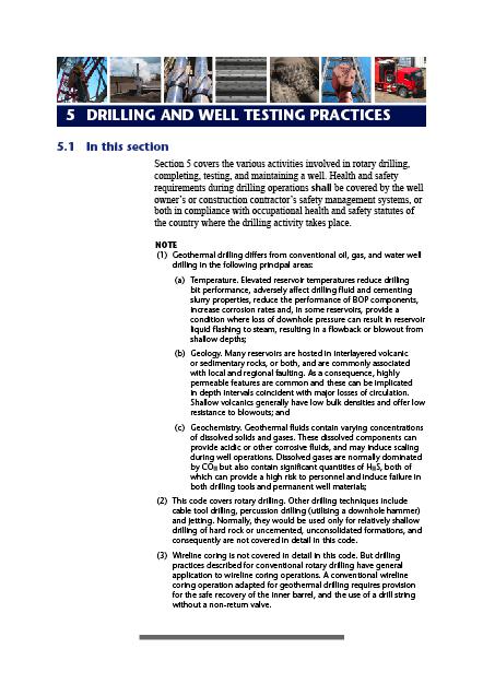
43 How to Calculate Theoretical Lag Time Circulation System Mud Tanks Suction Line Stand Pipe Discharge Line Rotary Hose Swivel Kelly Drill Pipe Degasser Desilter Desander Shale Shaker Mud Pump Return Line Annulus Drill Collar Drill Bit University of Texas at Austin The are 3 steps: 1. Calculate annular volume at certain depth of hole 2. Calculatepump output 3. Calculate the theoretical lag time
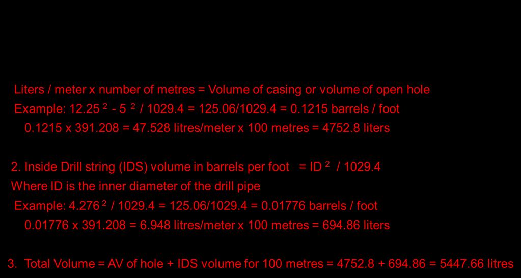
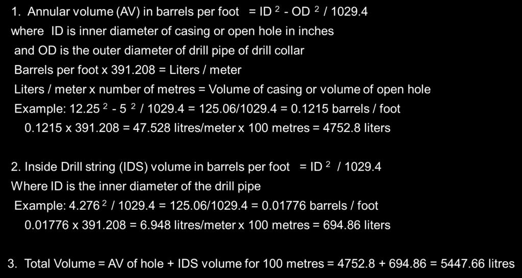

44


45 .
46 Well Logging and Testing Running downhole logs to assess cement placement. Down hole cameras. Dummy wireline runs. Mechanical calipers. Downhole retrieval of casing scale. Downhole videos or lead impression blockage. Downhole and well head conditions anticipated during logging and testing activities. Planned duration of the activities. Any changes that could happen downhole.

47 Well Logging and Testing

48 Well Logging and Testing Wireline BOP or lubricator. Discharging of an uncased hole can cause hole collapse due to reduction in downhole pressures. Pressure measurements taken with drilling mud in the well may not give true formation fluid pressures.
49 Well Logging and Testing Cooling of the hole from the drilling process could affect the temperature measurements. Fluid samples taken from a well during drilling may be contaminated with drilling fluids. All tools should be fishable.
50 Well Logging and Testing Thermal effects should be considered while selecting and running equipment. Wireline log data should be validated through comparable down and up logs across the same interval. Depth calibration against well construction records with provision for wireline stretch and expansion.

51 Drilling Records Quality data acquisition and retention of data and other information gathered during drilling including drilling parameters, cuttings logs and well logs.
52 Drilling Records Shall be permanently maintained and stored by well owner, and appropriate Government ministry or agency responsible for granting drilling licenses and maintaining geological data.
53 Drilling Records Purpose of drilling records: Subsequent monitoring of well condition. For any well workover, intervention or abandonment. As offset data for planning of subsequent wells. Assist directional drillers to avoid collision by later wells and ensure well tracks within legal boundaries. Reservoir engineering and understand the geology.
. Hole measurements and casing string depths.")
54 Drilling Records: Wells Well design and Drilling Program. Design modifications. Daily drilling activity records (detailed). Hole measurements and casing string depths. Casing specifications. Cementing reports.
55 Drilling Records: Wells Wellhead assembly (as built pictures). Downhole directional survey and pressure temperature surveys. Time Analysis and Cost Details. Unrecovered fish details. Wellhead location coordinates and datum level. Loss Circulation zones. Drilling Bits records. Detailed Master Log Cores and cuttings.
")
56 Drilling Records: Daily Daily drilling activity records (INFOSTAT Rimbase IADC Drilling Report)
57 Drilling Records: Daily Tool and drill string diameters. Drilling bit details. Drilling depth consumables drilling fluids. Casing and cementing reports (if applicable). Detailed daily activity report. Changes in drilling conditions. Pressures. Drilling parameters. Daily cost and time breakdown. Safety tracker and personnel on board (POB) numbers.

58 Drilling Records: Daily


59 Drilling Records: Daily


60 Chapter 6 Well Operations and Maintenance
61 Well Operation and Maintenance Procedure to be adopted during the life of a well. Maintaining well integrity Operated and maintained as per the code and and any changes need engineering assessment. When a potential defect is identified, additional monitoring and remedial work shall be undertaken ASAP (as soon as possible) depending on the nature and assessed risk.
62 Well Operation and Maintenance Well Monitoring specify monitoring frequency. Plan shall be established for both the downhole and surface components of all wells based on: o Subsurface conditions o Well history o Operating range o Changes in nearby wells o Ground subsidence o Well configuration o Equipment availability
63 Well Operation and Maintenance Multiple Well Monitoring cover multiple wells or reservoir: Scope of work shall included any well or wells excluded. Copies of plan to appropriate agencies. Processes to be put in place to record any variations and take necessary action.
64 Well Operation and Maintenance Identification of defects and Impairments: External or near surface leakages or corrosion of casing. Corrosion leakage of wellhead equipment. Broken or perforated casing and failed casing connections. Leaks in casing and buckled casing. Collapsed or corroded casing. Annular flow outside the casing. Chemical deposition or scale.
65 Observation of Change Plan shall observe the following type of changes: Changes is discharged fluid chemistry, enthalpy, pressures or flow rates of production wells. Changes in surface manifestations of geothermal flow, new hot areas on or near the well site. Any indications of fluid entering into a cemented casing annulus at surface or deterioration of cement. Any changes in flow from the casing annuli. Loss of pressure measured at a side valve when the well otherwise known to be under pressure.

66 Wellhead Inspection Record Documented Annual Inspection Wellhead pressure. Well Status (shut in, bleed, production, injection). Operating condition of well head valves. Leakage from valve gate or stem Condition seals. of protective paint coatings. Condition of anchor casing. Condition of the site and cellar drainage. Changes in vertical position of wellhead and position of CHF measured relative to the cellar datum.
67 Wellhead Maintenance Wellhead free of corrosion. Protective painted cleaned before fresh coat. Severe external corrosion of anchor casing is seen, casings outside shall removed to check casing and replaced after the remedial work is done. Anchor casing shall be replaced if pressure rating is compromised for the particular well. Or corrosion removed and casing painted. Casing annulus protection system should be maintained. No leakages across flanges, tappings, fittings, glands, valves and similar equipment and in sound operating conditions.

68 Risk Assessment Risk assessment for each well based on well monitoring and inspections, which should be documented. Any remedial works identified by the inspection program shall be completed as soon as practical. Especially when the potential deterioration could cause a risk to personnel safety and environmental damage.
69 Wells in Operation Master valve shall remain operational and capable of being closed at all times. Master valve nor side valves not to be used as flow control valves except in emergency situation. Master valve not to closed on a flowing well. Minimize the rapid change of temperature of well casings, cement sheath and wellhead. Controlled heating and cooling to mitigate this risk. Put the production well on bleed, increasing bleed rate or injecting hot fluid in the well are some measures.
70 Wells in Operation Bleeding of well should be done upstream of master valve through side valve, pipework should be anchored. Bleeding lines terminated at some distance away from the wellhead to avoid corrosion and accumulation of hazardous gases within low lying areas like the cellar. Designed in a way to avoid health or environmental hazard or noise nuisance. Any flow from the well shall be controlled by a valve, orifice plate, applies to low flow rates or high discharge rates.
71 Workovers Operations conducted on completed well using drilling rig or similar equipment to achieve: Repair or replacement of a wellhead component. Repair or replacement of damaged casing. Removal of scale deposits from the well. Installation or removal of non cemented liner from the well. Any other work inside the well needed to modify the existing conditions in the well.

72 Workovers More operations conducted: Workover operations shall comply with Section 5 needs and hazardous gases monitoring and managing. Prepare a well workover program including well control methods. Preferable to set a retrievable packer in the well than quenching the well, End of Well Workover report.
73 Quenching When quenching the well with cold water gradually cool the well in a controlled manner. Initial flow rates to be controlled at low level at first and then gradually increased until well is off pressure. Sequence of 25 liters/minute for the first hour increase in 25 liters/minute increments every 30 minutes. During quenching control the non condensable gases by venting in order to control wellhead pressure. Any gas pressure that builds up in the well should be reduced slowly by bleeding prior to well quenching.

74 Wellhead Removal and Replacement Replacement of wellhead components may be undertaken using a retrievable packer set inside sound casing. Snub the packer, set it and take an upward pull to ensure packer is set. Otherwise, well is quenched and kept in the quenched condition for twice the estimated maintenance time required.
.")
75 Wellhead Removal and Replacement Ensure adequate and secure water supply to keep well in the quenched condition. Any welding that is performed shall be in accordance with the welding procedures (pre- and post-heat). Cutting and removal of parts to avoid damage to other casing sections, if the wellhead height is changed new height.

76 Downhole Works A drilling wellhead including BOPs shall be installed in any well that has potential to discharge during the downhole works.
77 Downhole Works A new casing or scab liner across damaged or failed casing, shall be cemented over its full length. The well bore below scab liner should be isolated from any other operations using a drillable plug or packer set in the casing. When drilling scale in a permeable well, fluid returns and pump pressures should be continually monitored as bit can be plugged or drill string can get stuck.
78 Suspended Wells Cement plugs shall be placed (not less than 100 meters) of continuous cement inside production casing. Cement plug placed on bridge plug near production casing shoe above 10 meters of the liner. Minimize dilution of cement slurries by well fluids Cement should withstand ambient fluids and temperatures.
79 Suspended Wells Casing above the sound cement should be filled to surface with drilling fluid (bentonite). Pressure test cement plug to a sufficient test pressure to provide sufficient integrity for duration of well suspension. Wellhead can be removed except the CHF. End of Well Workover report shall be prepared.

80 Questions

81 Thank You! Sam Abraham, M.Sc. Linkedin
82 Sam Abraham Project Manager, Geothermal Drilling Engineer and Consultant Castille Drive La Quinta, California USA Cell USA: Cell Kenya: Cell Ethiopia: Skype: samasrig
The African Union Code of Practice for Geothermal Drilling
 Welcome The African Union Code of Practice for Geothermal Drilling African Union June 13-14, 2018 Addis Ababa, Ethiopia Sam Abraham Geothermal Engineer and Consultant Contents 1. Introduction 2. Well Design
Casing Design. Casing Design. By Dr. Khaled El-shreef
 Casing Design By Dr. Khaled El-shreef 1 Casing Design CONTENTS Function of Casing Casing Types & Tools Strength Properties Casing Specification Casing Design 2 1 RUNNING AND CEMENTING CASING Reasons for
APPENDIX A1 - Drilling and completion work programme
 APPENDIX A1 - Drilling and completion work programme Information about the well and drilling To the extent possible, the international system of units (SI) should be adhered to, and the drilling programme
Deepwater Horizon Incident Internal Investigation
 Not all Information has been verified or corroborated. Subject to review based on additional information or analysis. Deepwater Horizon Incident Internal Investigation 1 Areas of Discussion Investigation
W I L D W E L L C O N T R O L FLUIDS
 FLUIDS Fluids Learning Objectives You will learn about different fluids that can be used in well control. You will become familiar with the characteristics and limitations of fluids. You will learn general
IWCF Equipment Sample Questions (Surface Stack)
") IWCF Equipment Sample Questions (Surface Stack) 1. During a well control operation 4000 psi was shut in below the middle pipe rams. Ram type BOP data: Model: Cameron U type Rated Working Pressure: 15000
IWCF Equipment Sample Questions (Surface Stack) 1. During a well control operation 4000 psi was shut in below the middle pipe rams. Ram type BOP data: Model: Cameron U type Rated Working Pressure: 15000
Hydro-Mech Bridge Plug
 Manual No: 0620000303 Revision: F Approved By: Quality Engineer Date: 2014-9-9 Hydro-Mech Bridge Plug DESCRIPTION: Map Hydro-Mech Bridge Plug is hydraulically actuated and mechanically set. Compact, with
Blowout during Workover Operation A case study Narration by: Tarsem Singh & Arvind Jain, OISD
 1. Introduction An incident of gas leakage from a well took place during workover operations. Subsequently, the gas caught fire on the fourth day in which twelve persons were injured. Two contract workers,
IWCF Equipment Sample Questions (Combination of Surface and Subsea Stack)
") IWCF Equipment Sample Questions (Combination of Surface and Subsea Stack) 1. Given the volumes below, how much hydraulic fluid will be required to carry out the following operations (no safety margin)?
IWCF Equipment Sample Questions (Combination of Surface and Subsea Stack) 1. Given the volumes below, how much hydraulic fluid will be required to carry out the following operations (no safety margin)?
Float Equipment TYPE 925/926
 Type 925 Float Collar Plunger Valve Float Equipment For less demanding well conditions, such as shallower depths or lower pressures, Top- Co offers economical float equipment certified to API RP 10F category
RULES OF THE OIL AND GAS PROGRAM DIVISION OF WATER RESOURCES CHAPTER DRILLING WELLS TABLE OF CONTENTS
 RULES OF THE OIL AND GAS PROGRAM DIVISION OF WATER RESOURCES CHAPTER 0400-52-06 DRILLING WELLS TABLE OF CONTENTS 0400-52-06-.01 Drilling Equipment 0400-52-06-.03 Casingheads 0400-52-06-.02 Blowout Prevention
Texas Administrative Code
 TITLE 16 PART 1 CHAPTER 3 RULE 3.13 Texas Administrative Code ECONOMIC REGULATION RAILROAD COMMISSION OF TEXAS OIL AND GAS DIVISION Casing, Cementing, Drilling, Well Control, and Completion Requirements
Squeeze Cementing. Brett W. Williams Cementing Technical Advisor January 2016 Tulsa API Meeting
 Squeeze Cementing Brett W. Williams Cementing Technical Advisor January 2016 Tulsa API Meeting Definition Squeeze Cementing is the process of applying hydraulic pressure to force or squeeze a cement slurry
Study Guide IADC WellSharp Driller and Supervisor
 Times to Flow Check: Before pulling out of the hole Before pulling BHA into the BOP When bit is pulled into the casing Increase in cuttings at shakers with same ROP On connections Upon abnormal trip tank
Chapter 5 HORIZONTAL DRILLING
 Chapter 5 HORIZONTAL DRILLING Chapter 5 How much money am I about to put on the table for a horizontal well? Did I do sufficient planning? Keys to Successful Horizontal Wells Multi-disciplined teams working
WILD WELL CONTROL WARNING SIGNS OF KICKS
 WARNING SIGNS OF KICKS Warning Signs of Kicks Learning Objectives You will learn the warning signs that indicate the well may be kicking: Warning signs of kicks False kick indicators You will also learn
Type 967 Diamond Broaching Type 968 Sidewinder reamer shoe
 Type 965 float collar Type 966 float shoe 1. GENERAL INFORMATION & RECOMMENDATIONS Type 967 Diamond Broaching Type 968 Sidewinder reamer shoe Type 969 Sidewinder reamer shoe Float Equipment Top-Co Float
Engineered solutions for complex pressure situations
 SPECIAL SERVICES Engineered solutions for complex pressure situations Cudd Energy Services (CES) delivers custom engineered solutions to resolve complex pressure situations resulting from equipment failure
OCEAN DRILLING PROGRAM
 BIH OCEAN DRILLING PROGRAM www.oceandrilling.org Scientifi c Application Packers A packer is an inflatable rubber element that inflates to seal the annular space between the drill string and the borehole
float equipment OPERATING MANUAL TYPE 505/506 Float Equipment 1. INFORMATION & RECOMMENDATIONS Float Equipment
 Contents 1. GENERAL INFORMATION & RECOMMENDATIONS 1 2. INSTALLATION FLOAT EQUIPMENT 2 2.1 PRE-USE FIELD INSPECTION 2 2.2 POSITION FLOAT ON CASING STRING 3 3. RUNNING OF FLOAT EQUIPMENT 3 3.1 CIRCULATION
W I L D W E L L C O N T R O L PRESSURE BASICS AND CONCEPTS
 PRESSURE BASICS AND CONCEPTS Pressure Basics and Concepts Learning Objectives You will be familiarized with the following basic pressure concepts: Defining pressure Hydrostatic pressure Pressure gradient
Chapter 4 Key Findings. 4 Key Findings
 Chapter 4 Key Findings 211 4 Key Findings 212 Chapter 4 Key Findings This summarizes the key findings of the investigation team based on its extensive review of available information concerning the Macondo
Casing and Cementing Requirements
 Directive PNG005 May 2018 Revision 2.0 Governing Legislation: Act: The Oil and Gas Conservation Act Regulation: The Oil and Gas Conservation Regulations, 2012 Order: 148/18 Record of Change Revision Date
PROPOSED NEW SUB- CODE 1 RIG UP AND TEAR. Possibly Fits into Existing Code. 7/26/2018 Review PROPOSED NEW CODE EXISTING OPERATION
 NW NW 1 RIG UP AND TAR 1 no sub-code RIG UP AND TAR DOWN Start: Rig released from previous well, nd: Rig fully rigged up, acceptance tests successfully completed, and signed off. DOWN 1 1 Rig Under Tow
TAM Single SeT inflatable
 TAM Single SeT inflatable ReTRievAble PAckeRS Sets with pressure only Releases with straight pull or rotate Ideal for horizontal applications Sets in casing or open hole Runs on tubing, coiled tubing,
Shallow geothermal well systems
 GUIDELINES PRACTICE GOOD Shallow geothermal well systems SAFE OPERATION OF WELLS 150 METRES DEEP March 2018 These guidelines provide practical guidance to safely drill, operate, maintain, and abandon wells
Success Paths: A Risk Informed Approach to Oil & Gas Well Control
 API Winter E&P Standards Conference, Austin January 18, 2017 Success Paths: A Risk Informed Approach to Oil & Gas Well Control Dr. Dan Fraser Director, Strategic Alliances for Global Energy Solutions,
DAY ONE. 2. Referring to the last question, what mud weight would be required to BALANCE normal formation pressure?
 DAY ONE 1. Normal formation pressure gradient is generally assumed to be: A..496 psi/ft B..564 psi/ft C..376 psi/ft D..465 psi/ft 2. Referring to the last question, what mud weight would be required to
DUO-SQUEEZE H LCM Mixing Tables and Operating Procedures
 BAROID DUO-SQUEEZE H LCM Mixing Tables and Operating Procedures Prepared for: Prepared by: Submitted by: Submittal Date: All Customers Sharath Savari, Donald L. Whitfill Halliburton January 2014 1 Copyright
Inflatable Packer Single & Double. Single & Double Packer Dimension. Wireline Packer. Water Testing Packer (WTP) Packer
 Packer") Inflatable Packer Single & Double Single & Double Packer Dimension Wireline Packer Water Testing Packer (WTP) Packer Packer Working Pressure & Depth Chart Packer Water Hand Pump Packer Air Driven Pump
Inflatable Packer Single & Double Single & Double Packer Dimension Wireline Packer Water Testing Packer (WTP) Packer Packer Working Pressure & Depth Chart Packer Water Hand Pump Packer Air Driven Pump
WellCAP IADC WELL CONTROL ACCREDITATION PROGRAM
 WellCAP IADC WELL CONTROL ACCREDITATION PROGRAM WELL SERVICING OPERATIONS (WIRELINE, COILED TUBING & SNUBBING) CORE CURRICULUM AND RELATED FORM WCT-2WSI INTRODUCTORY LEVEL For information on how an course
Well Control Drill Guide Example Only. Drill Guide is the list of drills, questions and attributes that are in DrillPad.
 Well Control Drill Guide Example Only Drill Guide is the list of drills, questions and attributes that are in DrillPad. This Well Control Drill Guide will be used in conjunction with the rig-specific well
Why Do Not Disturb Is a Safety Message for Well Integrity
 Why Do Not Disturb Is a Safety Message for Well Integrity Presented at the Practical Well Integrity Conference 9-10 December, 2014 in Houston By Ron Sweatman, Principal Advisor, Reservoir Development Services,
W I L D W E L L C O N T R O L COMPLICATIONS
 COMPLICATIONS Complications Learning Objectives You will learn to detect changes that deviate from established trends. You will learn how to respond to problems such as: Pump problems String problems Hole
6-3/4 DUAL PORTED PBL BYPASS SYSTEM (Applicable to sizes 6-1/4 & 6-1/2 also)
") RECEIVING PBL AT RIG SITE TITLE: Operating Instructions for -3/4 PBL -3/4 DUAL PORTED PBL BYPASS SYSTEM (Applicable to sizes -1/4 & -1/2 also) OPERATING INSTRUCTIONS 1. On receipt of PBL Bypass Tools at
RECEIVING PBL AT RIG SITE TITLE: Operating Instructions for -3/4 PBL -3/4 DUAL PORTED PBL BYPASS SYSTEM (Applicable to sizes -1/4 & -1/2 also) OPERATING INSTRUCTIONS 1. On receipt of PBL Bypass Tools at
WellCAP IADC WELL CONTROL ACCREDITATION PROGRAM
 WellCAP IADC WELL CONTROL ACCREDITATION PROGRAM WIRELINE OPERATIONS CORE CURRICULUM AND RELATED FORM WCT-2WLF FUNDAMENTAL LEVEL The purpose of the core curriculum is to identify a body of knowledge and
Manual Actuated Boiler Blowdown Valves
 Manual Actuated Boiler Blowdown Valves Installation and Maintenance Instructions 1. Safety information 2. General product information 3. Installation 4. Operation 5. Maintenance 6. Spare parts p.1 1. Safety
Perforating Options Currently Available in Horizontal Shale Oil and Gas Wells. Kerry Daly, Global BD Manager- DST TCP
 MENAPS 2013 Perforating Options Currently Available in Horizontal Shale Oil and Gas Wells Kerry Daly, Global BD Manager- DST TCP MENAPS 13-17 WELL FLOW MANAGEMENT TM Scope/ Contents: MENAPS 13-17 Study
SUPPLEMENT Well Control for Drilling Operations Workover & Completion for Drillers Core Curriculum and Related Learning Objectives
 SUPPLEMENT Well Control for Drilling Operations Workover & Completion for Drillers Core Curriculum and Related Learning Objectives Form WSP-02-DO-SU-WOC-D Revision 0 13 February 2015 DC 2015 COPYRGHT PROTECTED
MST21 Stainless Steel Balanced Pressure Thermostatic Steam Trap
 1250650/6 IM-P125-07 ST Issue 6 MST21 Stainless Steel Balanced Pressure Thermostatic Steam Trap Installation and Maintenance Instructions 1. Safety information 2. General product information 3. Installation
On-Off Connector Skirt
 On-Off Connector Skirt Retrievable Packers & Accessories The On-Off Connector Skirt is compact, reliable, fully sealing, J-type tubing disconnect device that automatically engages and releases with a small
Restoring Fluid Flow in Tubing Strings
 Restoring Fluid Flow in Tubing Strings Andrew Roth, Product Manager Fike Corporation Fike Hydraulic Tubing Drains (HTD) for use with deep hole drilling tools, downhole devices and other oil and off shore
BLACK HILLS PLATEAU PRODUCTION COMPANY
 BLACK HILLS PLATEAU PRODUCTION COMPANY DRILLING PROGRAM Homer Deep Unit 9 11CH SHL: 300 FNL, 200 FWL, NWNW Sect. 9 T8S R98W BHL: 1350 FSL, 2100 FEL NWSE Sect. 15 T8S R98W Garfield & Mesa Counties, Colorado
Disposal/Injection Well Pressure Test Report (H-5)
") RAILROAD COMMISSION OF TEXAS Disposal/Injection Well Pressure Test Report (H-5) Lauryn McFarland Engineering Technician Summary When Mechanical Integrity Test (MIT) is required How to file MIT How to perform
RAILROAD COMMISSION OF TEXAS Disposal/Injection Well Pressure Test Report (H-5) Lauryn McFarland Engineering Technician Summary When Mechanical Integrity Test (MIT) is required How to file MIT How to perform
Extended leak off testing
 Extended leak off testing Rev: 1.0 03/01/01 Purpose To ensure minimal operational time and risk exposure to personnel, process, production and equipment. The following extended leak off test procedures
1. The well has been shut in on a kick and the kill operation has not started.
 Well Control Methods Day 2 1. The well has been shut in on a kick and the kill operation has not started. Shut in drill pipe pressure Shut in casing pressure 500 psi 700 psi After stabilization, both pressures
BANDAR PANJI-1 WELL CONTROL INCIDENT REPORT
 BANDAR PANJI-1 WELL CONTROL INCIDENT REPORT EXECUTIVE SUMMARY I was requested by management to review the Banjar Panji-1 drilling operations from the conception of the Integrated Drilling Management approach
Drilling Efficiency Utilizing Coriolis Flow Technology
 Session 12: Drilling Efficiency Utilizing Coriolis Flow Technology Clement Cabanayan Emerson Process Management Abstract Continuous, accurate and reliable measurement of drilling fluid volumes and densities
Offshore Managed Pressure Drilling Experiences in Asia Pacific. SPE paper
 Offshore Managed Pressure Drilling Experiences in Asia Pacific SPE paper 119875 Authors: Steve Nas, Shaun Toralde, Chad Wuest, SPE, Weatherford Solutions Sdn Bhd, SPE, Weatherford Indonesia SPE, Weatherford
Practice Exam IADC WellSharp Driller and Supervisor
 Workover & Completion Day 4 1. In a workover operation of a shut in well a Lubricator is being used together with a Wireline BOP / Wireline Valve. Which Barrier is classified as the Primary Barrier? A.
Bridge Plugs, Ball Drop & Caged Ball Plugs For Zone Isolation
 Bridge Plugs, Ball Drop & Caged Ball Plugs For Zone Isolation ADVANTAGE composite bridge plug, caged ball and ball drop (flow thru) frac plug provide a means to isolate multiple zones during high pressure
CLASS D - SENSITIVE LEAK TEST GAS AND BUBBLE METHOD. 1.1 To provide definitive requirements for PNEUMATIC pressure testing of piping systems.
 Page 1 of 7 CLASS D - SENSITIVE LEAK TEST GAS AND BUBBLE METHOD 1. SCOPE 1.1 To provide definitive requirements for PNEUMATIC pressure testing of piping systems. 1.2 The piping system as used herein is
MSC-P and MSC-N Manifolds for Steam Distribution and Condensate Collection
 1170850/1 IM-P117-36 ST Issue 1 MSC-P and MSC-N Manifolds for Steam Distribution and Condensate Collection Installation and Maintenance Instructions 1. Safety information 2. General product information
PTRT 1471: Exploration and Production I. Chapter 6: Drilling and Well Completion
 PTRT 1471: Exploration and Production I Chapter 6: Drilling and Well Completion Well Planning Drilling is a major investment (over $100m for offshore) Planning is aimed at maximizing investment Wells are
Pasquale Imbò e Marco Pelucchi ENI S.pA;
 7th European Gas Well Deliquification Conference Innovative Failsafe Capillary Injection System Resolves Liquid Loading in Gas Well with a Cost- Effective Solution that Maintaining Production and Well-Safety
5k Slickline Lightweight Pressure Control Equipment 4 ID
 5k Slickline Lightweight Pressure Control Equipment 4 ID Table of Contents 5k Slickline Lightweight Pressure Control Equipment 4 ID... 1 Hydraulic Slickline Stuffing Box... 3 Wireline Lubricators... 4
SUPPLEMENT Well Control for Drilling Operations Workover & Completion for Supervisors Core Curriculum and Related Learning Objectives
 SUPPLEMENT Well Control for Drilling Operations Workover & Completion for Supervisors Core Curriculum and Related Learning Objectives Form WSP-02-DO-SU-WOC-S Revision 0 13 February 2015 DC 2015 COPYRGHT
International Well Control Forum. IWCF Drilling Well Control Syllabus Level 3 and 4 March 2017 Version 7.0
 International Well Control Forum IWCF Drilling Well Control Syllabus and 4 March 2017 Version 7.0 IWCF Drilling Well Control Syllabus and 4 Contents Guidance Notes... 5 1.1. Introduction... 5 1.2. Who
1 Scope... 2 Functions of cementing float equipment... 3 Definitions... 4 Calibration... 5 Test Categories... 6 General...
 American Petroleum Institute Contents Page 1 Scope... 2 Functions of cementing float equipment... 3 Definitions... 4 Calibration... 5 Test Categories... 6 General... 7 Apparatus and Materials... 8 High-temperature/high-pressure
DB Bridge Plug. Features. Benefits. Applications
 DB Bridge Plug The WELLFIRST Premium Cast Iron Bridge Plug designed to run on electric line. Rated between 2000-10000-psi differential, and 300 F from above and below. Features Field Proven Design Constructed
VortexFlow DX (Downhole) Tool Installation Instructions
 Tool Installation Instructions") VortexFlow DX (Downhole) Tool Installation Instructions www.vortextools.com Page 1 of 10 The VortexFLOW tools are based upon Technology that is a result of U.S.A. patents 6,151,751; 6,659,118; 6,749,374;
VortexFlow DX (Downhole) Tool Installation Instructions www.vortextools.com Page 1 of 10 The VortexFLOW tools are based upon Technology that is a result of U.S.A. patents 6,151,751; 6,659,118; 6,749,374;
Spiratec ST14, ST16 and ST17 Sensor Chambers and sensors
 0862050/1 IM-P086-18 MI Issue 1 Spiratec ST14, ST16 and ST17 Sensor Chambers and sensors Installation and Maintenance Instructions 1. Safety Information 2. General product information 3. Installation 4.
Hydraulic Punch Drivers
 SERVICE MANUAL 7804SB / 7806SB Quick Draw 7704SB / 7706SB Quick Draw Flex Quick Draw Hydraulic Punch Drivers Serial Codes AHJ and YZ Read and understand all of the instructions and safety information in
PV4 and PV6 Piston Valves
 1181250/1 IM-P118-05 ST Issue 1 PV4 and PV6 Piston Valves Installation and Maintenance Instructions 1. Safety information 2. General product information 3. Installation 4. Commissioning 5. Operation 6.
WELL SUSPENSION AND ABANDONMENT GUIDELINES AND INTERPRETATION NOTES OFFICE OF THE REGULATOR OF OIL AND GAS OPERATIONS
 WELL SUSPENSION AND ABANDONMENT GUIDELINES AND INTERPRETATION NOTES OFFICE OF THE REGULATOR OF OIL AND GAS OPERATIONS CONSULTATION AND ENGAGEMENT DRAFT MAY 17, 2016 If you would like this information in
TP1 and TP2 Temporary Cone Shaped Strainers
 1698051/2 IM-P169-07 ST Issue 2 TP1 and TP2 Temporary Cone Shaped Strainers Installation and Maintenance Instructions TP1 1. Safety information 2. General product information 3. Installation and commissioning
Advanced Applications of Wireline Cased-Hole Formation Testers. Adriaan Gisolf, Vladislav Achourov, Mario Ardila, Schlumberger
 Advanced Applications of Wireline Cased-Hole Formation Testers Adriaan Gisolf, Vladislav Achourov, Mario Ardila, Schlumberger Agenda Introduction to Cased Hole Formation tester Tool specifications Applications
Worked Questions and Answers
 Worked Questions and Answers A Learning Document for prospective Candidates For the Rotary Drilling Well Control Test Programme Copyright, IWCF June 2000 Revision No.1, November 2000 IWCF 2000 page 1 of
Industry Code: Alberta Small Employer OHS Legislated Requirements
 This document is a guideline only. Employers have a responsibility of assessing all applicable occupational health and safety legislation, for the tasks they are performing. Services in this industry can
W I L D W E L L C O N T R O L SNUBBING OPERATIONS
 SNUBBING OPERATIONS Snubbing Operations Learning Objectives You will learn - Various activities suitable for snubbing operations. Best practices and techniques for conducting snubbing operations. The types
WellCAP IADC WELL CONTROL ACCREDITATION PROGRAM
 WellCAP IADC WELL CONTROL ACCREDITATION PROGRAM WELL SERVICING OPERATIONS SNUBBING CORE CURRICULUM AND RELATED FORM WCT-2SS SUPERVISORY LEVEL The purpose of the core curriculum is to identify a body of
UIB30 and UIB30H Sealed Inverted Bucket Steam Traps for use with Pipeline Connectors
 1130050/4 IM-P113-02 ST Issue 4 UIB30 and UIB30H Sealed Inverted Bucket Steam Traps for use with Pipeline Connectors Installation and Maintenance Instructions 1. Safety information 2. General product information
Oil, Gas and Salt Resources of Ontario
 Oil, Gas and Salt Resources of Ontario Provincial Operating Standards Version 2.0 Oil, Gas and Salt Resources of Ontario Provincial Operating Standards, Version 2.0 Version 2.0 of the Oil, Gas and Salt
Coal and Water Protection. PADEP: Well Plugging & Subsurface Activities Division Bureau of Oil and Gas Planning & Program Management
 Coal and Water Protection PADEP: Well Plugging & Subsurface Activities Division Bureau of Oil and Gas Planning & Program Management Review of Applicable Regulations & Laws Coal protective casing: A string
2-7/8 TRIPLE PORTED PBL BYPASS SYSTEM
 RECEIVING PBL AT RIG SITE TITLE: Operating Instructions for 2-7/8 Triple Port PBL 1-10-201 2-7/8 TRIPLE PORTED PBL BYPASS SYSTEM OPERATING INSTRUCTIONS 1. On receipt of PBL Bypass Tools at Rig site, the
GEOTHERMAL WELL COMPLETION TESTS
 GEOTHERMAL WELL COMPLETION TESTS Hagen Hole Geothermal Consultants NZ Ltd., Birkenhead, Auckland, New Zealand. ABSTRACT This paper reviews the measurements that are typically made in a well immediately
Self-managing shallow geothermal well systems
 GUIDELINES PRACTICE GOOD Self-managing shallow geothermal well systems FOR PCBUs WITH GEOTHERMALLY HEATED POOLS OR PLANT March 2018 These guidelines are for PCBUs (including local authorities) who have
The key to connectivity
 The key to connectivity Kerry Daly, Global BD Manager, Tubing Conveyed Perforating (TCP) First published by Oilfield Technology, November 2015 Connecting oil or gas-bearing formations with the wellbore
1. UPDATE 12/12/2014: What wells are regulated under the MIA Program? Must they be drilled, stimulated, and completed? Must they be in production?
 PLEASE NOTE THAT ALL USES OF THE WORD OPERATOR IN THIS DOCUMENT REFER TO THE ACT 13 DEFINITION OF WELL OPERATOR AND THUS, REFERENCE THE PERMIT HOLDER (PERMITEE) FOR THE WELL. ANY ENFORCEMENT ACTIONS UNDER
OPERATING MANUAL DOUBLE ACTING DRILLING INTENSIFIER HYDRAULIC TYPE
 Page 1 of 8 OPERATING MANUAL DOUBLE ACTING DRILLING INTENSIFIER HYDRAULIC TYPE Size Series 6.50" 478 Reviewed And Approved By: Signature: Initials: Date: Page 2 of 8 Section OPERATING MANUAL DOUBLE ACTING
North American sealing solutions Bridge Plug Ball Drop Frac Plug Caged Ball Frac Plug
 North American sealing solutions Bridge Plug Ball Drop Frac Plug Caged Ball Frac Plug The North American Sealing Solutions composite bridge plug, caged ball and ball drop (flow thru) frac plug provide
Date of Issue: July 2016 Affected Publication: API Specification 16C, Choke and Kill Equipment, Second Edition, March 2015 ADDENDUM 1
 Date of Issue: July 2016 Affected Publication: API Specification 16C, Choke and Kill Equipment, Second Edition, March 2015 ADDENDUM 1 Page 16, Section 4.6, delete the entire section and renumber all subsequent
TSS21 Sealed Thermostatic Steam Tracer Trap
 1255050/4 IM-P125-10 ST Issue 4 TSS21 Sealed Thermostatic Steam Tracer Trap Installation and Maintenance Instructions 1. Safety information 2. General product information 3. Installation 4. Commissioning
KBV21i and KBV40i Key Operated Boiler Blowdown Valves Installation and Maintenance Instructions
 4059051/3 IM-P405-48 EMM Issue 3 KBV21i and KBV40i Key Operated Boiler Blowdown Valves Installation and Maintenance Instructions 1. Safety information 2. General product information 3. Installation 4.
Engineering Data Sheet
 Page 1 of 6 CE MARKING AND THE PRESSURE EQUIPMENT DIRECTIVE 97/23/EC Valves must be installed into a well designed system and it is recommended that the system be inspected in accordance with the appropriate
W I L D W E L L C O N T R O L SHUT-IN PROCEDURES
 SHUT-IN PROCEDURES Shut-in Procedures Learning Objectives You will learn general shut-in procedures: For surface BOPs. For subsea BOPs. You will learn to interpret shut-in pressures and be able to perform
HOT OILING OPERATIONS ALL HSE PRC 172. Approved By: Manager, HSE Performance Assurance. Table of Contents
 Owner: HSE Performance Assurance ALL HSE PRC 172 Approved By: Manager, HSE Performance Assurance Retention Code: CG01 CA Revised: March 2015 Review Frequency: Five years or less Table of Contents 1.0 Purpose...
Understanding pressure and pressure
 CHAPTER 1 1-1 PRESSURE BASICS Remember to think downhole. The concepts provided in this section cover the foundations for good well control. Understanding pressure and pressure relationships is important
KBV21i and KBV40i Air Actuated Boiler Blowdown Valves
 4059051/1 IM-P405-48 AB Issue 1 KBV21i and KBV40i Air Actuated Boiler Blowdown Valves Installation and Maintenance Instructions 1. Safety information 2. General product information 3. Installation 4. Commissioning
Spirax Compact FREME Flash Recovery Energy Management Equipment
 IM-UK-cFREME UK Issue 1 Spirax Compact FREME Flash Recovery Energy Management Equipment Installation and Maintenance Instructions 1. Safety information 2. General product information 3. Installation 4.
Wellwork Chronological Regulatory Report
 Well Name: UNIVERSITY 49 #0808H Field: Lin (Wolfcamp) S/T/R: / / County, State: Location Desc: Operator: Enduring Resources, LLC Project Type: Completion District: Southern Project AFE: DV02151 AFE's Associated:
Successful Deployment of a Long Gun String Via Intelligent Coiled Tubing
 Successful Deployment of a Long Gun String Via Intelligent Coiled Tubing Parry Hillis: Technical Manager BakerHughes David Ayre: BP Well Perforation Specialist Jim Gilliat: TCP/DST Business Development
BaraShield -664 LCM Standard Field Application Procedure
 BaraShield -664 LCM Standard Field Application Procedure Prepared for: Prepared by: Submitted by: Submittal Date: All Customers Sharath Savari, Donald L. Whitfill Halliburton March 2016 1 Copyright 2011
Subsea Safety Systems
 Subsea Safety Systems The ELSA-HP has been developed to service the high pressure horizontal tree completion and intervention market. With systems designed and qualified up to 15,000 psi, 250 degf and
ANNEX AMENDMENTS TO THE INTERNATIONAL CODE FOR FIRE SAFETY SYSTEMS (FSS CODE) CHAPTER 15 INERT GAS SYSTEMS
 CHAPTER 15 INERT GAS SYSTEMS") Annex 3, page 2 ANNEX AMENDMENTS TO THE INTERNATIONAL CODE FOR FIRE SAFETY SYSTEMS (FSS CODE) CHAPTER 15 INERT GAS SYSTEMS The text of existing chapter 15 is replaced by the following: "1 Application This
Annex 3, page 2 ANNEX AMENDMENTS TO THE INTERNATIONAL CODE FOR FIRE SAFETY SYSTEMS (FSS CODE) CHAPTER 15 INERT GAS SYSTEMS The text of existing chapter 15 is replaced by the following: "1 Application This
Monte Besler Consultant FracN8R Consulting LLC UNITED STATES
 Monte Besler Consultant FracN8R Consulting LLC UNITED STATES Engineered Safety and Environmental Aspects of Well Construction and Fracturing Design Monte Besler FRACN8R Consulting, LLC Surface Considerations
HydroPull. Extended-Reach Tool. Applications
 Extended-Reach Tool HydroPull This tool incorporates a cycling valve that momentarily interrupts the flow to create water-hammer pressure pulses inside coiled or jointed tubing used in horizontal well
BT6HC Hygienic Sanitary Balanced Pressure Steam Trap for High Capacity and CIP/SIP Applications
 1800350/6 IM-P180-12 ST Issue 6 BT6HC Hygienic Sanitary Balanced Pressure Steam Trap for High Capacity and CIP/SIP Applications Installation and Maintenance Instructions 1. Safety information 2. General
Hydrostatic Pressure Testing
 General An experienced or qualified person will be put in charge of hydro and should meet with the supervisor in charge of the job prior to test. Customer expectations should be clarified prior to beginning
Hard or Soft Shut-in : Which is the Best Approach?
 HARD - SOFT shut-in? Hard or Soft Shut-in : Which is the Best Approach? March '93 INTRODUCTION There is now reasonable acceptance through-out the industry for the use of a hard shut-in procedure following