AD500 INSTRUCTION MANUAL. Product #20080
|
|
|
- Maud Kelly
- 5 years ago
- Views:
Transcription

1 AD500 INSTRUCTION MANUAL Product #20080
2 Thank you for purchasing your Aquatica AD500 housing. Before you start to use your new housing, please read these instructions carefully. Keep this manual in a safe place for future reference. This instruction manual assumes that the camera user is already familiar with the Nikon D500 camera. If not, please read your camera instruction manual before attempting to use the housing. Please visit the Aquatica Digital website for further information. AQUATICA PRODUCT NUMBERS NK OPT KT NK -VC OPT -VC KT-VC Aquatica housing for Nikon D500 with double Nikonos connector Aquatica housing for Nikon D500 Including dual optical connectors Aquatica housing for Nikon D500 Including a single Ikelite connector + vacuum pump Aquatica housing for Nikon D500 Including a single Nikonos connector + vacuum pump Aquatica housing for Nikon D500 Including dual optical connectors + vacuum pump Aquatica housing for Nikon D500 Including a single Ikelite connector + vacuum pump NOTE: Shown housing illustrations may differ from your actual housing depending on the ordered version. 2 AD500 INSTRUCTION MANUAL Table of contents
3 Table of contents Table of contents... 3 Safety precautions... 4 Product specifications... 5 Package contents... 6 Housing schematics... 7 Housing components & functions... 7 Housing functions... 8 Housing preparation Camera preparation and installation Port mounting Port removal Accessories Surveyor sensor Vacuum pump Flash triggering Aqua View finder Care and maintenance Housing components Sacrificial anodes O-rings Storage and transportation Warranty Table of contents 3 AD500 INSTRUCTION MANUAL
4 Safety precautions Please carefully read and follow the following precautions and recommendations: Improper transportation, handling or use of this housing might cause a flood or a malfunction. Follow all recommendations stated in the next sections of this manual. Never remove, change a port or open the housing in a location where sand or similar foreign material might come in contact with an O-ring. Be wary of strong winds as they could potentially be carrying sand or other harmful particulate matter. Always perform a simple preventive seal test without the camera inside after doing maintenance on the housing. Non-authorized use of third party accessories, as well as modifications and/or alterations not specifically authorized by Aquatica may affect performance, cause poor functioning of the controls or impair the sealing integrity of the housing. Always handle the ports carefully. Protect them when not in use to avoid scratching the acrylic or glass surface of ports and windows. Always confirm that the ports remain properly attached before rinsing the housing. When rinsing without a wired strobe, confirm that the bulkhead strobes connectors are sealed with their plug. Never jump into the water with the housing. Have the system handed to you after you have made your entry or have it lowered to you on a rope. Never handle the housing by grabbing the port, or if using one, the Aqua View finder. Make sure that boat staff are familiar with these procedures and advise them to manipulate the housing by using the grips provided with the housing. 4 AD500 INSTRUCTION MANUAL Safety precautions
5 Product specifications Construction Physical Features Housing body Surface treatment Windows Grip handles Dimensions WxHxD (w/o grips) Weight (w/o camera) Buoyancy Depth rating Ergonomic control placement Aqua View finder compatibility Moisture/vacuum alarm Flash capability T6 Aluminium Anodized + powder coated Optical acrylic Black PVC 256mm x 173mm x 145mm x 6.83 x kg 6.1 lb Slightly negative 100 msw fsw Easy access to following controls: Shutter Front dial wheel Rear dial wheel REC Fn1 & White balance ISO Exposure compensation Zoom-focus wheel Aqua View finder 45 Aqua View finder 180 Supplied with the Surveyor moisture and vacuum sensor alarm. Compatible with the following depending on flash option: Optical triggering Nikonos-style bulkhead Ikelite-style bulkhead 1 Note that all of the AE-M1II flash triggering options are not TTL compatible. Product specifications 5 AD500 INSTRUCTION MANUAL
6 Package contents AD500 housing Handle grips (2) with screws (2) AD500 instruction manual Lens chart Spare housing seal O-ring CR 2032 coin cell battery Aquatica O-ring lubricant container Set of Allen keys Optical Flash trigger with optical bulkheads or double Nikonos connector or single Ikelite connector Vacuum pump (for NK-VC, OPT-VC and KT-VC kits) 6 AD500 INSTRUCTION MANUAL Package contents
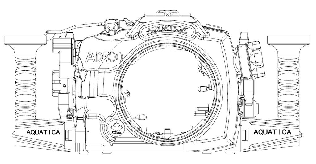
7 Housing schematics Housing components & functions 1 Aquatica Grips X2 2 Port Lock Lever Control 3 Aquatica OPT 4 Aquatica Port Cover 5 16mm Accessory Port 6 ISO External Lever Control 7 AF-ON Lever Control 8 Rear Dial Control 9 Aquatica Stainless Steel Latch 10 On/Off Control Knob 11 Record Control Lever 12 Exposure Compensation Control Leaver 13 Shutter Release Lever 14 Front Dial Control 15 FN1 Control Lever Housing schematics 7 AD500 INSTRUCTION MANUAL
8 Housing functions 16 Up Selection Button 17 Right Selection Button 18 Center Selection Button 19 Down Selection Button 20 Left Selection Button 21 INFO Button 22 LV Button 23 Live View Switch Selector Knob 24 Help Button 25 LCD Monitor Window Port 26 Removable Viewfinder Eye Piece 27 Mode Dial Knob 28 Trash Button 29 Playback Button 30 Menu Button 31 Protect Button 32 Playback Zoom In Button 33 Thumbnail/ Playback Zoom Out Button 34 Wet Alarm LED Light 35 OK Button 36 FN2 Button 8 AD500 INSTRUCTION MANUAL Housing schematics
9 37 AF Point Selection Button 38 MODE Button 39 QUAL Button 40 16mm/.5 Inch Accessory Port 41 White Balance Control Lever 42 Zoom/ Focus Knob 43 Lens Release Control Lever 44 AF/M Selector Knob Housing schematics 9 AD500 INSTRUCTION MANUAL
10 Housing preparation Follow these steps to prepare your AD500 housing for use: STEP 1: Assemble your handle grips onto your housing using the provided screws and Allen keys. STEP 2: STEP 3: STEP 4: WARNING: If you are adding any shoes, brackets or ball mounts onto your housing, mount them using the intended ¼-20 UNC threaded holes. You can use the threaded holes on the handle grips, the top one or the bottom ones for your tripod. Mount your strobes and their arms onto the housing. For details about optical flash triggering and wired bulkheads, refer to the Accessories, Flash triggering section (page 20). Follow your strobe manufacturer manual and its recommendations. Before use, remove the main O-ring seal from its groove and carefully verify that the O-ring and its groove are free from scratches or foreign matter. Lubricate the O-ring with a light coat of silicone grease. For proper handling of O-rings, follow the detailed instructions outlined in the 10 AD500 INSTRUCTION MANUAL Housing preparation
 for more details on sensor operation. Camera preparation and installation Follow these steps to prepare your Nikon D500 camera for use with your housing.")
11 Care and maintenance, O-rings section (page 22). STEP 5: Insert the provided CR 2032 coin cell battery in the Surveyor alarm. Read Accessories, Surveyor sensor (page 16) for more details on sensor operation. Camera preparation and installation Follow these steps to prepare your Nikon D500 camera for use with your housing. It is also advisable before inserting the camera into the housing, in order to save valuable time underwater, to set your camera shooting preferences beforehand. STEP 1: Remove the quick release tray from the housing by pressing down on the lever and then pulling the tray out. STEP 2: Lift the camera s LCD screen out of the way and carefully place the camera on the tray. Make sure that the camera is properly aligned with the pin and the stoppers on the tray then tighten the mounting screw. Finally lower the LCD screen so that it rests on the two rear stoppers at an angle. STEP 3: [IMPORTANT] To avoid any interference while inserting the camera in the housing, pull out the Lens Release (43), AF/M (44) and Zoom/ Focus Knob (42) located on the left of the housing as well as the FN 1 Control lever (15) located on the Right. Camera preparation and installation 11 AD500 INSTRUCTION MANUAL

12 Before inserting the camera, position the ON/OFF switch of both the camera and the housing (10) to the OFF position (rotating the ON/OFF switch of the housing counter-clockwise to a stop). STEP 4: Slide the quick release tray and the camera into the housing; it will lock itself into place. STEP 5: Before closing the housing align the AF/F (44), Lens Release (43) and FN1 (15) controls with the ones on the camera switch positions. And make sure that the ON/OFF lever (10) is working properly. 12 AD500 INSTRUCTION MANUAL Camera preparation and installation

13 STEP 5: Hold the latch on each side (9), align the pins on the front shell and rear shell and bring them together. Engage each latch on its strike tab then press both latches simultaneously. Finally, verify that the safety tabs on each latch are engaged by trying to lift the latch up, and visually check that the O-ring remained properly seated and no obstruction is present [IMPORTANT] In the event that you feel any unusual resistance when attempting to close the rear door, do not force the closure. Reopen, inspect carefully for any potential obstruction such as ON/OFF switch position and try again. Camera preparation and installation 13 AD500 INSTRUCTION MANUAL

14 Port mounting The AD500 housing is equipped with a bayonet locking system that firmly attaches compatible ports and extensions. STEP 1: WARNING: Before mounting the port, remove the O-ring seal from its groove and carefully verify that the O-ring and its groove are free from scratches or foreign matter. Lubricate the O-ring with a light coat of silicone grease. Also check that the O-ring mating surface on the housing is clean and free of any physical damage. For proper handling of O-rings, follow the detailed instructions outlined in the, O-rings section. STEP 2: Place the housing on its back on a soft and steady surface. STEP 3: Place the port or extension ring inside the housing bayonet. Align the bayonet using the four alignment notches in the housing. STEP 4: Push with even force on both sides of the port or extension ring until you feel it snap into place. Make sure the bayonet is completely inside the housing. 14 AD500 INSTRUCTION MANUAL Port mounting
15 STEP 5: Rotate the port clockwise until it stops. Do not force it. If there is too much resistance, take the port off, check the O-ring and see that the port or extension ring is properly seated before attempting to rotate it again. STEP 6: Confirm that the port or extension ring is safely locked in the housing by gently trying to rotate it counter-clockwise. The bayonet lock should prevent any counter-clockwise rotation. WARNING: Never attempt to manually focus the camera if it is set to autofocus mode with a mounted focus gear engaged. This will strain the focus mechanism motor and might damage your lens. Port removal STEP 1: Press the port release lever (2) and rotate the port or extension counter clockwise. STEP 2: Carefully pull the port or extension off the bayonet. Port removal 15 AD500 INSTRUCTION MANUAL

16 Accessories Surveyor sensor Your AD500 housing comes standard with the Surveyor moisture alarm. This sensor device has two distinct purposes, a moisture detection circuitry and an ambient pressure sensor circuitry; both are integrated on the same circuit board. A CR 2032 coin cell battery is provided to power your moisture alarm. NOTE: Once a battery is installed, the moisture detector function of the Surveyor alarm will remain on standby and does not need to be activated. If not being used for a prolonged period of time, it is recommended to remove the battery from the sensor circuit to avoid unnecessary drain. 1 Sensor circuit 2 Battery holder 3 Vacuum power switch 4 CR V battery 5 External LED point 6 Integrated warning LED 7 Probe wire harness WARNING: If you are only using the moisture alarm function without the vacuum, it is recommended to perform a quick test of the circuit before every dive. To do so, simply moisten the tip of your finger and establish contact between the board probes (#7). This should trigger the water alarm. If it fails to activate, check that the battery is correctly inserted and replace it with a fresh one if required. 16 AD500 INSTRUCTION MANUAL Accessories
17 Standby mode Water detected LED is off System is on standby Red LED flashing with audible alarm Water is making contact with probe Moisture alarm mode LED code: If you want to benefit from the full capabilities of your Surveyor sensor, you can order the optional vacuum pump system (#19228). The vacuum function of the Surveyor offers the user an efficient monitoring tool to check its housing sealing integrity before and during his dive. The next table shows the vacuum sensor mode LED code. See Accessories, Error! eference source not found. section (page Error! Bookmark not defined.) for the required procedure to obtain a vacuum using the pump. Vacuum sensor mode LED code: Standby mode Vacuum ready % Vacuum 100% Vacuum Over-depressurization 2 Vacuum standby Loosing vacuum % Lost vacuum 0-40% Water detected LED is off System is on standby Green LED flashing System is ready to be depressurized Yellow LED flashing Building vacuum inside housing Green LED solid Required level of vacuum is achieved Green LED flashing System is getting over depressurized Green LED flashing every 4 sec Housing system is holding vacuum Yellow LED flashing Housing is losing vacuum over time Red LED flashing with audible alarm 4 Housing has lost vacuum Red LED flashing with audible alarm Water is making contact with probe 2 Everything is OK, just stop pumping vacuum. 3 Indication of a slow leak behavior. 4 Alarm will stay on during 30 seconds before going back to standby mode. Accessories 17 AD500 INSTRUCTION MANUAL
18 Vacuum pump A vacuum pump will allow you to fully benefit from the capabilities of your Surveyor sensor. Your pump kit (either #19228 or #19233) includes the following parts: 1 Vacuum pump 2 Pressure valve 3 Retaining nut * Aquatica lubricant If your pump was not factory installed or bought separately, you will need to install the pressure valve bulkhead on your housing. The AD500 is compatible with pump kit #19228 and pump kit # Using the proer adapters, both can be installed in the 16mm/.5 accessory Port (40) To install your valve: STEP 1: STEP 2: STEP 3: STEP 4: Remove the existing plug by unscrewing the hexagonal nut inside. Lubricate the valve bulkhead O-ring using provided Aquatica O-ring lubricant (see, O-rings section for more information). Carefully insert the valve bulkhead into the selected port, slightly rotating the valve while pushing will facilitate the insertion. Tighten the retaining nut. 18 AD500 INSTRUCTION MANUAL Vacuum pump
19 To use your vacuum monitoring system: STEP 1: STEP 2: Prior to closing your housing, put your Surveyor sensor in vacuum mode by pressing the activation switch on the board. The Surveyor green LED should be flashing rapidly upon activation. Close your housing using procedure outlined in the Error! Reference ource not found. section. STEP 3: Remove the valve plug (#1) by sliding the quick-disconnect collar (#2). STEP 4: STEP 5: STEP 6: WARNING: STEP 7: Insert the pump stem (#5) in the pressure valve and release the quick disconnect collar (#2). Make sure the pressure release plug (#6) is screwed all the way in (clockwise). Build vacuum inside your housing by pumping the handle (#7). The amount of pumping required will vary according to the housing dimensions and the port configuration being used. However, the proper amount of vacuum should always be attainable within a reasonable delay. Refer to vacuum LED code table in Accessories, Surveyor sensor section. Be careful not to over-depressurize the housing. This will trigger the alarm and require the sensor to be reset. Remove the pump by sliding the quick-disconnect collar (#2) and put back the plug (#1) in the pressure valve. If your housing fails to maintain a constant vacuum, proceed a thorough inspection of the user serviceable O-rings of the housing. If unsuccessful in determining the source of the leak, refrain from immersing the housing and return it to your authorized service center for inspection. Vacuum pump 19 AD500 INSTRUCTION MANUAL
 and remove pressure release plug (#6). Once the hissing sound stops, you can remove the pump (STEP 7).")
20 NOTE: Once your housing is under vacuum, it is important to pressurize it back to ambient pressure before attempting to remove your port or open the housing. To pressurize it back, insert the pump back into the valve (STEP 4) and remove pressure release plug (#6). Once the hissing sound stops, you can remove the pump (STEP 7). The housing is now back at ambient pressure. Flash triggering There are three flash options compatible with the AD500 housing: Optical triggering (#20080-OPT and #20080-OPT-VC) Optical bulkheads LED flash trigger Double Nikonos-style bulkhead (#20080-NK and #20080-NK-VC) Ikelite-style bulkhead (#20080-KT and #20080-IKT-VC) For Nikonos and Ikelite style bulkheads, simply insert the velcroed board inside your camera hot-shoe. Both options come already wired with the required flash circuit board. All switches must be in the OFF (lower) position on the switchboard. NOTE: Note that none of the offered flash triggering options on the AD500 housing are TTL compatible. 20 AD500 INSTRUCTION MANUAL Vacuum pump
21 Aqua View finder The AD500 housing is compatible with both the 180 Aqua View finder (#20054) and the 45 Aqua View finder (#20059). To install your Aqua View finder, you will have to remove the standard eyepiece. To remove your standard eyepiece: STEP 1: Using an O-ring removal tool, remove the eyepiece retaining O-ring. STEP 2: Carefully pull the eyepiece body out of the housing. To install your Aqua View finder: STEP 1: WARNING: STEP 2: Carefully verify that the O-ring and its groove are free from scratches or foreign matter. Lubricate the O-ring with a light coat of silicone grease. Also check that the O-ring mating surface on the housing is clean and free of any physical damage. For proper handling of O-rings, follow the detailed instructions outlined in the, O-rings section. Insert your Aqua View finder inside your housing. Be sure to align the Aqua View finder with the aligning pin on the housing. STEP 3: Install your Aqua View finder retaining O-ring WARNING: It is highly recommended to perform a simple seal test without the camera after performing the installation. View following section for details. Vacuum pump 21 AD500 INSTRUCTION MANUAL
22 Care and maintenance With basic care and a regular maintenance schedule, your Aquatica housing will provide years of enjoyment and satisfaction in producing spectacular underwater images. Please follow all undermentioned care and maintenance instructions. Housing components After every salt water dive, soak and/or rinse your housing system in fresh water. It should soak for a minimum of 30 minutes. Operate all the controls several times, while soaking, to dislodge any trapped salt water residues. Periodically remove the hand grips for storage and transportation to avoid having the thread of the attachment bolts fuse on to the housing. Unscrew, clean and lubricate the bolts with a small amount of WD-40 or Zinc-based lubricant. WARNING: Use WD-40 or any lubricant carefully, sparingly and only on metal to metal surfaces. WD-40 or other petroleum-based lubricants can damage the acrylic on the ports, the optical surfaces of a lens or O-rings. Sacrificial anodes Two anodes are attached to the bottom parts of the housing to prevent galvanic corrosion due to electrolysis. As time goes and depending on use, they will deteriorate and need replacement. Contact your dealer to order replacement anodes (#19220). O-rings When replacing the main seal O-ring, place the entire O-ring over the O-ring groove and start by pushing the O-ring in the corners. Work your way around the O-ring making sure it is snugly sitting in the groove. Avoid going solely in one direction as doing so will stretch the O-ring material and possibly prevent it from properly seating. When working your housing or port O-rings, please follow these instructions: Never use a sharp instrument when removing an O-ring as this may damage the sealing surface of the groove or the O-ring itself. A dedicated O-ring tool, a dull pointed object or the edge of a credit card usually works well. 22 AD500 INSTRUCTION MANUAL Care and maintenance
23 Once removed, the O-ring should be inspected for damage. Carefully check that it is free of nicks or cuts and that it retains its original round profile. O- rings that appear to be damaged should be immediately replaced with new ones. Rinse the O-ring with fresh water and dry it with a clean lint free cloth. Clean the O-ring groove (the channel where the O-ring sits) with a cotton swab. Make sure to remove any lint the cotton swab may leave behind. Wipe the matching sealing surface part of the housing with a clean lint-free cloth. Lubricate the O-ring with a thin layer of Aquatica O-ring lubricant (# 19213) until it appears to be smooth and shiny. Do not over lubricate. Use just enough lubricant so the O-ring will pull smoothly through your fingers. Excessive amounts of grease will only attract and trap dirt onto the O-ring. Confirm that the Port and extension ring O-rings are properly and evenly seated in their O-ring groove. To reinstall the clean and lubricated main O-ring of the housing: Place the entire O-ring over the groove and start by pushing the O-ring in at each corner. Push the O-ring at each side to distribute it evenly across the surface before finally working in the rest of the O-ring. Never start at one end and work your way around the O-ring. This creates uneven tension on the O-ring which may cause the O-ring to stretch. WARNING: When changing ports or O-rings, a simple seal test without the camera inside should be performed. Strapping a weight to the housing and lowering the unit to a depth of 30 to 50 feet of water for at least 10 minutes will assure you that you have a proper seat of the new port or O-ring. This test, though time consuming and often considered unnecessary, may save your camera equipment from irreparable water damage. Care and maintenance 23 AD500 INSTRUCTION MANUAL

24 The internal O-rings of the housing are not user replaceable. While these O-rings are not as susceptible to damage as the main seal, rinsing the housing properly with fresh water to flush out salt crystals and sand residues will assure trouble free operation. Aquatica recommends yearly maintenance of the internal O-rings. Authorized service centers are offering this service with factory-approved procedures and replacement parts. You can check the closest service center to you on the Aquatica website. WARNING: Only use petroleum free O-ring lubricants such as our Aquatica O-ring lubricant (#19213). Petroleum-based lubricants, used by some manufacturers to lubricate their Silicone-made O-rings will cause the O- ring material to swell. This will cause difficult installation and will likely result in O-ring being damaged or pinched. Storage and transportation Store and transport the housing in a sturdy, shock proof container and avoid travelling with the camera mounted inside the housing. In the event of an impact, especially on the external push buttons, the impact could potentially be transferred to the camera controls and damage them. ring seal. When travelling by air or in situation where atmospheric pressure changes are foreseen, leave the housing opened, or alternatively, remove the port and the eye piece. Doing so allows equalization of the air pressure inside the housing with ambient pressure. Failure to follow this recommendation may cause an internal pressure build up which could potentially force ports or acrylic windows to pop out or potentially unseat their O- 24 AD500 INSTRUCTION MANUAL Storage and transportation
25 Warranty PLEASE READ CAREFULLY One year limited warranty All Aquatica products are guaranteed against defects in material or workmanship for one (1) full year from the date of purchase for consumer use. these same products when used commercially will carry a 90-day warranty. No statutory warranty applies. Camera housed in Aquatica housings are not covered under this warranty and any water damage sustained due to installation error or any other reason is not the responsibility of Aquatica. Therefore, the appropriate insurance should be maintained by the user. Warranty does not apply to replaceable seals or damages to impacts or abrasive surfaces. Warranty applies only to products purchased from authorized Aquatica dealers and does not extend beyond the original retail purchaser. Unauthorized modifications or repairs will automatically void this warranty. This applies to removal of serial numbers and Aquatica identification labels. To obtain service during or after the warranty period you must notify Aquatica at +1 (514) and ship by registered mail (insured) only, enclosing your proof of purchase to: Aquatica Digital 3025 De Baene Montreal (Quebec) H4S 1K8 Mark clearly on your package Canadian goods returned for repair. Do not ship by any other means. Unauthorized packages will be refused. YOUR SERIAL NUMBER Warranty 25 AD500 INSTRUCTION MANUAL
AQUATICA PRODUCT NUMBERS
 Thank you for purchasing your Aquatica A6500 housing. Before you start to use your new housing, please read these instructions carefully. Keep this manual in a safe place for future reference. This instruction
Contents: 1. Introduction
 Camera Underwater Housing G11 (Canon) User Manual Contents: 1. Introduction 2. Specifications 3. Function Controls 4. Set up Instructions 5. Use & Care of Housing 6. Service 7. Warranty 1. Introduction
Underwater Housing for Canon EOS M
 Underwater Housing for Canon EOS M User Manual 1 Table of Contents 1. Introduction 2. Specifications 3. Function Controls 4. Set up Instructions 5. Use & Care of Housing 6. Service 7. Warranty 1. Introduction
Underwater Housing for Panasonic Lumix DMC-ZS60, DMC-TZ80
 Underwater Housing for Panasonic Lumix DMC-ZS60, DMC-TZ80 Product Number 6170.60 Product Registration Please register your product at ikelite.com within 15 days of purchase. Our product registration database
Underwater Housing for Canon G7X Mark II
 Underwater Housing for Canon G7X Mark II Product Number 6146.08 Product Registration Please register your product at ikelite.com within 15 days of purchase. Our product registration database is the best
Underwater Housing for Sony Alpha A6000
 Underwater Housing for Sony Alpha A6000 Product Number 6910.61 Product Registration Please register your product at ikelite.com within 15 days of purchase. Our product registration database is the best
Underwater TTL Housing for Panasonic Lumix LX100, Leica D-Lux (Typ 109)
") Underwater TTL Housing for Panasonic Lumix LX100, Leica D-Lux (Typ 109) Product Number 6171.11 Product Registration Please register your product at ikelite.com within 15 days of purchase. Our product registration
Underwater TTL Housing for Panasonic Lumix LX100, Leica D-Lux (Typ 109) Product Number 6171.11 Product Registration Please register your product at ikelite.com within 15 days of purchase. Our product registration
Underwater Housing for Sony Alpha a6300 Mirrorless Camera
 Underwater Housing for Sony Alpha a6300 Mirrorless Camera Product Number 6910.63 Product Registration Please register your product at ikelite.com within 15 days of purchase. Our product registration database
200DLM/A Underwater Housing for Canon EOS M50, EOS Kiss M
 200DLM/A Underwater Housing for Canon EOS M50, EOS Kiss M Product Number 6973.15 Product Registration Please register your product at ikelite.com within 15 days of purchase. Our product registration database
200DLM/A Underwater Housing for Canon EOS M5 Mirrorless Digital Camera
 200DLM/A Underwater Housing for Canon EOS M5 Mirrorless Digital Camera Product Number 6973.05 Product Registration Please register your product at ikelite.com within 15 days of purchase. Our product registration
200DLM/B Underwater Housing for Panasonic Lumix G85, G80 Mirrorless Micro Four-Thirds Digital Camera
 200DLM/B Underwater Housing for Panasonic Lumix G85, G80 Mirrorless Micro Four-Thirds Digital Camera Product Number 6961.08 Product Registration Please register your product at ikelite.com within 15 days
Underwater Housing for Canon EOS 100D Rebel SL1. Housing Kit for Canon EOS 100D Rebel SL1. Product Registration. Product Number 6970.
 Underwater Housing for Canon EOS 100D Rebel SL1 Product Number 6970.03 Housing Kit for Canon EOS 100D Rebel SL1 Product Number 6970.04 Product Registration Please register your product at ikelite.com within
OLYMPUS Tough TG-3 and TG-4 Waterproof Housing MANUAL
 OLYMPUS Tough TG-3 and TG-4 Waterproof Housing Recsea CWOM-TG3/4 MANUAL Please read this manual before use. NTF CORPORATION UH Division http://www.seatool.net INTRODUCTION OLYMPUS Tough TG-3 and TG-4 Waterproof
CANON PowerShot G9 X Waterproof Housing MANUAL
 CANON PowerShot G9 X Waterproof Housing Recsea CWC-G9X MANUAL Please read this manual before use. NTF CORPORATION UH Division http://www.seatool.net INTRODUCTION CANON PowerShot G9 X Waterproof Housing
Canon PowerShot G16 Underwater Housing. Recsea WHC-G16 MANUAL. Please read this manual before use. NTF CORPORATION UH Division.
 Canon PowerShot G16 Underwater Housing Recsea WHC-G16 MANUAL Please read this manual before use. NTF CORPORATION UH Division http://www.seatool.net INTRODUCTION CANON POWERSHOT G16 Underwater Housing WHC-G16
User Manual GRI- 1500Li
 User Manual GRI- 1500Li Your Cart Tek caddy cart was thoroughly quality control checked and road tested before being shipped to your address. We do everything possible to assure that your caddy is in perfect
200DLM/A Underwater Housing for Sony Alpha A6400 Mirrorless Cameras
 200DLM/A Underwater Housing for Sony Alpha A6400 Mirrorless Cameras Product # 6911.64 Product Registration Please register your product within 15 days of purchase. Our product registration database is
M3-LED. Operator s Manual. Operator s Manual MADE IN THE USA USA
 M3-LED Operator s Manual Operator s Manual MADE IN THE USA USA Section TABLE OF CONTENTS Page Warnings and Cautions... 1 M3-LED Parts Diagram... 4 Mounting... 6 Dismounting... 8 Switch Operation... 10
TTL Converter for Nikon DSLR with Nikonos N5 Connector (Version 2)
") TTL Converter for Nikon DSLR with Nikonos N5 Connector (Version 2) Product Number 4302.3 I n s t r u c t i o n M a n u a l Thank you for your purchase of Ikelite equipment. Please read this instruction
TTL Converter for Nikon DSLR with Nikonos N5 Connector (Version 2) Product Number 4302.3 I n s t r u c t i o n M a n u a l Thank you for your purchase of Ikelite equipment. Please read this instruction
Fantasea F580EX Mark II Flash Housing for Canon 580EX Mark II Speedlite
 Fantasea F580EX Mark II Flash Housing for Canon 580EX Mark II Speedlite 1 TABLE OF CONTENTS FANTASEA F580EX MARK II FLASH HOUSING FOR CANON 580EX MARK II SPEEDLITE... 1 TABLE OF CONTENTS... 2 GENERAL INFORMATION...
ROPV R40 E Series User Manual
 HARBIN ROPV INDUSTRY DEVELOPMENT CENTER ROPV R40 E Series User Manual For Use with the Following ROPV Pressure Vessel Models: R40 300E R40 450E Headquarters Tel:(+86)451-82267301 Fax:(+86)451-82267303
Assembly Drawing: W-311B-A01, or as applicable Parts List: W-311B-A01-1, or as applicable Special Tools: , , &
 REDQ Regulators Model 411B Barstock Design Powreactor Dome Regulator OPERATION AND MAINTENANCE Contents Scope..............................1 Installation..........................1 General Description....................1
Thank you for purchasing your new Empire Reloader B Sound-Activated 3-Speed Paintball Hopper!
 Thank you for purchasing your new Empire Reloader B Sound-Activated 3-Speed Paintball Hopper! Should you require any technical assistance on the use of this product, or if your product needs servicing,
PT-054. PT-054 Instruction Manual Printed in China VM730901
 PT-054 Instruction Manual PT-054 http://www.olympus.com/ 2012 Printed in China VM730901 Thank you for buying the Underwater Case PT-054 (hereinafter Case). Please read this instruction manual carefully
OLYMPUS OM-D E-M1 Waterproof Housing MANUAL
 OLYMPUS OM-D E-M1 Waterproof Housing Recsea RDH-OMEM1 MANUAL Please read this manual before use. NTF CORPORATION UH Division http://www.seatool.net INTRODUCTION OLYMPUS OM-D E-M1 Waterproof Housing RDH-OMEM1
PROPORTIONING VALVE. Model 150 INSTRUCTION MANUAL. March 2017 IMS Company Stafford Road
 PROPORTIONING VALVE Model 150 INSTRUCTION MANUAL March 2017 IMS Company 10373 Stafford Road Telephone: (440) 543-1615 Fax: (440) 543-1069 Email: sales@imscompany.com 1 Introduction IMS Company reserves
Photo: Jonas Wall ANTARES OVAL DRY GLOVE SYSTEM BY SI TECH.
 Photo: Jonas Wall ANTARES OVAL DRY GLOVE SYSTEM BY SI TECH www.sitech.se The Oval revolution We want to congratulate you on your purchase of the ANTARES Modular Dry Glove System. The oval design and quick
SOTR Special Operations Tactical Respirator
 SOTR Special Operations Tactical Respirator OPERATOR S MANUAL FOR INDIVIDUAL RESPIRATORY PROTECTION OPS-CORE 2018 OMM G055-1000 REV. B INTRODUCTION ABOUT YOUR SOTR The Ops-Core Special Operations Tactical
GRI-1300/1350Li. User Manual
 User Manual GRI-1300/1350Li Your Cart Tek caddy cart was thoroughly quality control checked and road tested before being shipped to your address. We do everything possible to assure that your caddy is
C - SERIES. Height Adjustable Portable Goal Supports. Installation & Owner s Instructions C1000 C2000. Made in the USA
 C - SERIES Height Adjustable Portable Goal Supports C1000 C2000 Installation & Owner s Instructions Made in the USA This manual explains the proper installation, operation, and maintenance of your Schutt
Misaligned Folds Paper Feed Problems Double Feeds Won t Feed FLYER Won t Run iii
 Operator s Manual Table of Contents Operator Safety... 1 Introduction... 2 Unpacking and Setup... 3 Unpacking... 3 Setup... 4 FLYER Overview... 5 FLYER Diagram... 5 Capabilities... 5 Control Panel... 6
Installation Instructions
 Installation Instructions COLONY SOFT 7.0 Centerset Lavatory Faucet 7.0 with Speed Connect Drain Congratulations on purchasing your American Standard faucet with the Speed Connect drain, a features found
icreasepro Creaser Operators Manual
 6-2013 Version 3.0 icreasepro Creaser Operators Manual WWW.MBMCORP.COM 800-223-2508 TABLE OF CONTENTS SPECIFICATIONS.1a SAFETY PROCEDURES/CARE & MAINTENANCE..1b COMPONENT IDENTIFICATION 2 TOUCH SCREEN
FX IMPACT OWNER S MANUAL
 made in sweden FX IMPACT OWNER S MANUAL Warranty Information All FX Airguns carry a One Year Warranty against faulty workmanship and defective materials. If it becomes necessary, first contact the dealer
DL 8 Dome Port. Product Registration. Product Number 75340
 DL 8 Dome Port Product Number 75340 Product Registration Please register your product at ikelite.com within 15 days of purchase. Our product registration database is the best way for us to get a hold of
Multi-Probe Sampling System User Guide & Manual
 Multi-Probe Sampling System User Guide & Manual Rev. 06/05/12 Part #22200012 Table of Contents CHAPTER 1: SYSTEM DESCRIPTION... 2 FUNCTION AND THEORY... 3 SYSTEM COMPONENTS... 4 CHAPTER 2: SYSTEM INSTALLATION...
Underwater Housing for Olympus Stylus 1S
 Underwater Housing for Olympus Stylus 1S Product Number 6139.51 Product Registration Please register your product at ikelite.com within 15 days of purchase. Our product registration database is the best
Maintenance and Repair. AirHawk II Air Mask. Second Stage Regulator. Order No.: /02 Prnt. Spec (I) MSAsafety.
 MSAsafety.") Maintenance and Repair Second Stage Regulator Order No.: 10104241/02 Prnt. Spec. 10000005389(I) MSAsafety.com WARNING! Read this manual carefully before servicing the device. The device will perform as
Maintenance and Repair Second Stage Regulator Order No.: 10104241/02 Prnt. Spec. 10000005389(I) MSAsafety.com WARNING! Read this manual carefully before servicing the device. The device will perform as
Bray/ VAAS O-Ported Series Knife Gate Valve 770/780 Series Operation and Maintenance Manual
 Bray/ VAAS Knife Gate Valve 770/780 Series Operations and Maintenance Manual Table of Contents Definition of Terms 1 Safety Instructions 1 Introduction 2 Unpacking 2 Storage 2 Installation 2 Commissioning
Product Information News
 Product Information News MMR SECOND STAGE REGULATOR VALVE CORE MSA has changed its recommended rebuilding of the MMR Second Stage Regulator s bypass sleeve assembly during the annual inspection. Based
PT-EP06 Instruction Manual
 PT-EP06_EN.Book Page 1 Monday, September 26, 2011 5:01 PM PT-EP06 Instruction Manual EN PT-EP06_EN.Book Page 1 Monday, September 26, 2011 5:01 PM Thank you for buying the Underwater Case PT-EP06 (hereinafter
INSTRUCTION MANUAL. January 23, 2003, Revision 0
 INSTRUCTION MANUAL Model 810A In-Vitro Test Apparatus for 310B Muscle Lever January 23, 2003, Revision 0 Copyright 2003 Aurora Scientific Inc. Aurora Scientific Inc. 360 Industrial Parkway S., Unit 4 Aurora,
Installation, Operation & Maintenance Manual for Flo-Max Coupler Bracket Model FM150
 Installation, Operation & Maintenance Manual for Flo-Max Coupler Bracket Model FM150 January 2013 Form FVC 084 - Rev 02 IMPORTANT: KEEP THIS DOCUMENT WITH THE PRODUCT UNTIL IT REACHES THE END USER. 1.
ANTARES. User Manual ANTARES OVAL DRY GLOVE SYSTEM BY SI TECH. Photo: Jonas Andersson, Lysekil
 ANTARES User Manual Photo: Jonas Andersson, Lysekil ANTARES OVAL DRY GLOVE SYSTEM BY SI TECH ANTARES - User manual We want to congratulate you on your purchase of the ANTARES, a Dry Glove System developed
PT-048. µ TOUGH-8010/STYLUS TOUGH-8010/µ TOUGH-6020/STYLUS TOUGH-6020
 PT-048 µ TOUGH-8010/STYLUS TOUGH-8010/µ TOUGH-6020/STYLUS TOUGH-6020 µ TOUGH-8010/STYLUS TOUGH-8010/µ TOUGH-6020/STYLUS TOUGH-6020 µ TOUGH-8010/STYLUS TOUGH-8010/µ TOUGH-6020/STYLUS TOUGH-6020 µ TOUGH-8010/STYLUS
Owner s Guide. ElevateSUP.com
 Owner s Guide ElevateSUP.com IMPORTANT READ THIS IMPORTANT INFORMATION BEFORE USING YOUR STAND UP PAD- DLEBOARD Disregarding any of the safety precautions and instructions contained in the owner s manual
IMPORTANT CO2/ HPA AIR TANK SAFETY INSTRUCTION AND GUIDELINES. Tank valves must be installed or removed by qualified personnel.
 !WARNING! IMPORTANT SAFETY INSTRUCTION AND GUIDELINS!WARNING! IMPORTANT CO2/ HPA AIR TANK SAFETY INSTRUCTION AND GUIDELINES GETTING STARTED This Paintball Marker is NOT A TOY. Misuse can cause serious
User's Manual. Heavy Duty Dissolved Oxygen Meter. Model
 User's Manual Heavy Duty Dissolved Oxygen Meter Model 407510 Introduction Congratulations on your purchase of Extech's Heavy Duty Dissolved Oxygen / Temperature Meter which simultaneously displays Dissolved
PT -053 PT-053 Ins truction M a nual
 PT-053 Thank you for buying the Underwater Case PT-053 (hereinafter Case). Please read this instruction manual carefully and use the product safely and correctly. Please keep this instruction manual for
Underwater Housing for Sony Cyber-shot DSC- HX80, HX90V(/B), HX99, WX500(/B)
, HX99, WX500(/B)") Underwater Housing for Sony Cyber-shot DSC- HX80, HX90V(/B), HX99, WX500(/B) Product # 6115.90 Product Registration Please register your product within 15 days of purchase. Our product registration database
Underwater Housing for Sony Cyber-shot DSC- HX80, HX90V(/B), HX99, WX500(/B) Product # 6115.90 Product Registration Please register your product within 15 days of purchase. Our product registration database
DIRECT DRIVE DIXIE DOUBLE SEAMER Model 25D
 OPERATOR'S MANUAL DIRECT DRIVE DIXIE DOUBLE SEAMER Model 25D LUBRICATE DAILY: A. Gears inside gear housing at chuck shaft (1) Oil B. Seam rolls and cam rolls (4) - Oil C. Seam roll levers through gear
AR STYLE FIREARMS OWNER'S MANUAL: OPERATION, HANDLING, DISASSEMBLY / REASSEMBLY & SAFETY INSTRUCTIONS
 AR STYLE FIREARMS OWNER'S MANUAL: OPERATION, HANDLING, DISASSEMBLY / REASSEMBLY & SAFETY INSTRUCTIONS - DO NOT DISCARD THIS MANUAL - READ THIS MANUAL CAREFULLY, PAYING CLOSE ATTENTION TO THE INSTRUCTIONS
Pressure Dump Valve Service Kit for Series 2300 Units
 Instruction Sheet Pressure Dump Valve Service Kit for Series 00 Units. Overview The Nordson pressure dump valve is used to relieve hydraulic pressure instantly in Series 00 applicator tanks when the unit
USER GUIDE TO POWER ASSISTED BIKES
 USER GUIDE TO POWER ASSISTED BIKES 1 PAGE CONTENTS Page. 3 Unpacking Page. 3-4 Easy steps to get started Page. 5 General Assembly Instructions Page. 6 Aligning H/Bars, Page. 7 Tightening pedals onto Crank
OWNER S MANUAL READ THIS MANUAL BEFORE USING YOUR NEW AIRGUN
 OWNER S MANUAL READ THIS MANUAL BEFORE USING YOUR NEW AIRGUN FX SUPER SWIFT Table of Contents Warranty Specifications General Instructions Operating Instructions Trigger Adjustments Care & Maintenance
MAINTENANCE PROCEDURE FOR X 650
 MAINTENANCE PROCEDURE FOR X 650 X 650 25. juli 2005-1/6 MAINTENANCE PROCEDURE FOR X 650 2 ND STAGE WARNING: This maintenance procedure is only for appointed Scubapro technicians that completed a course
RG1200 Service and Repair Manual
 Dive Rite RG 1200 Regulator Service and Repair Manual Page 1 Text and Photography by Pete Nawrocky Copyright ( ) 1999-2000, Lamartek, Inc., dba Dive Rite RG1200 Service and Repair Manual First Stage.........................................
RB70 Automatic Diluent Valve Maintenance Manual. Version 1.1 November 2006 Written by Tino de Rijk. Page 1 of 23
 RB70 Automatic Diluent Valve Maintenance Manual Version 1.1 November 2006 Written by Tino de Rijk Page 1 of 23 Table of Contents 1. Introduction... 3 2. ADV diagram and parts list (Pre June 2006)... 4
Contents. Stainless Steel Side Block. 1.1 Separating the Side Block. Stainless Steel Side Block Reassembly of. Assembly from the Helmet Shell
 Separating the Side Block Assembly from the Helmet Shell Contents SSB-1 SSB-3 SSB-5 SSB-5 SSB-7 1.1 Separating the Side Block Assembly from the Helmet Shell 1.2 Side Block Assembly Replacement 1.3 Defogger
3 Post Pressure Fit System Owner s Manual
 3 Post Pressure Fit System Owner s Manual Use and Care Trouble Shooting Warranty Information Table of Contents 3 Post Pressure Fit System Introduction... 3 Overview of the 3 Post Pressure Fit System...
Operation Manual Guillotine Cutter RC-5
 Operation Manual Guillotine Cutter RC-5 Technical Specifications General Safety/Operating Instructions Using the Guillotine Cutter/Crimper Blade Change Instructions Maintenance Instructions This is a detailed
DM-MBST (English) Dealer's Manual. ROAD MTB Trekking. City Touring/ Comfort Bike. Shifting lever. EZ-FIRE Plus ST-EF500 ST-EF510
 Dealer's Manual. ROAD MTB Trekking. City Touring/ Comfort Bike. Shifting lever. EZ-FIRE Plus ST-EF500 ST-EF510") (English) DM-MBST001-00 Dealer's Manual ROAD MTB Trekking City Touring/ Comfort Bike URBAN SPORT E-BIKE Shifting lever EZ-FIRE Plus ST-EF500 ST-EF510 CONTENTS IMPORTANT NOTICE... 3 TO ENSURE SAFETY...
(English) DM-MBST001-00 Dealer's Manual ROAD MTB Trekking City Touring/ Comfort Bike URBAN SPORT E-BIKE Shifting lever EZ-FIRE Plus ST-EF500 ST-EF510 CONTENTS IMPORTANT NOTICE... 3 TO ENSURE SAFETY...
USER MANUAL
 C Cimarron Sports 1-888-816-6517 www.cimarronsports.com Combo Pitching Machine USER MANUAL TABLE OF CONTENTS Thank you for purchasing the Cimarron Combo Pitching Machine. The Cimarron Combo Pitching Machine
User Manual GRX- 1250Li
 User Manual GRX- 1250Li Your Cart Tek caddy cart was thoroughly quality control checked and road tested before being shipped to your address. We do everything possible to assure that your caddy is in perfect
DelVal Flow Controls Private limited
 DelVal Flow Controls Private limited (A DIVISION OF DelTech CONTROLS LLC, USA) DelVal Series 50/5, 5A/5B Butterfly Valves INSTALLATION, OPERATION AND MAINTENANCE MANUAL ENGINEERING DATA SHEET E.D.S. NO
Duo/Trio Office Bike Owner s Manual
 Duo/Trio Office Bike Owner s Manual Welcome Congratulations on choosing to enhance your productivity and wellness with LifeSpan. You ve made a healthy decision, as the need for increased amounts of daily
Flashlight. Hand Lanyard. 36 Super Bright LED Bulbs. Sensor
 1 1. Introduction The LED 360 Light is a new LED light from Fantasea, which features 36 super bright LED bulbs and a focus light dim out sensor, which shuts the light off for a second whenever a flash
BMW Motorrad. Installation Instructions. BMW Motorrad Communications System for Schuberth C3
 BMW Motorrad Installation Instructions BMW Motorrad Communications System for Schuberth C3 Order No. 01 29 2 219 831 BMW Motorrad 05/2011 Be sure to read these instructions carefully and completely before
INSTRUCTIONS FOR THE CATALYST CASE FOR IPHONE 5/5S
 INSTRUCTIONS FOR THE CATALYST CASE FOR IPHONE 5/5S The Catalyst case is a waterproof, drop proof all weather case that allows you to utilize your iphone 5/5S in, around, and under water. This case has
Pressure Fit System - Two Post Version Owner s Manual
 Pressure Fit System - Two Post Version Owner s Manual Use and Care Trouble Shooting Warranty Information Table of Contents Pressure Fit System Introduction... 3 Overview of the Pressure Fit System... 3
HELMETS SAVE LIVES!!! ALWAYS WEAR A PROPERLY FITTED HELMET WHEN YOU RIDE YOUR SCOOTER. DO NOT RIDE AT NIGHT. AVOID RIDING IN WET CONDITIONS.
 HELMETS SAVE CORRECT FITTING - MAKE SURE YOUR HELMET COVERS YOUR FOREHEAD. LIVES!!! ALWAYS WEAR A PROPERLY FITTED HELMET WHEN YOU RIDE YOUR SCOOTER. DO NOT RIDE AT NIGHT. AVOID RIDING IN WET CONDITIONS.
5 Gallon EVkeg Operation Manual
 EV 5 Gallon EVkeg Operation Manual www.evcontainer.com 1 Liner Removal Before any attempt is made to remove the liner, the keg should be fully depressurized. It will be impossible to rotate the handle
Service and Repair Operative Manual MC9 1 st STAGE. MC9 1 st Stage. 1 st STAGE MC9. Jannuary Rev. MC9 /B Ed. C/13
 MC9 1 st Stage 137 1 st STAGE MC9 Jannuary 2009 - Rev. MC9 /B Ed. C/13 138 WARNING! This manual is intended for use by expert technicians who should attend or have already received training in equipment
User Manual 1 P a g e Rev. V1.6-EN 11/08/2014
 User Manual 1 P a g e Rev. V1.6-EN 11/08/2014 Copyright Disclaimer Trademarks and patents Intended use Contact info 2011 Inflotrolix, Inc. This document may not be copied in whole or in part or otherwise
Model PSI Compressor with 3-Gallon Air Tank 12VDC
 Model 6350 150 PSI Compressor with 3-Gallon Air Tank 12VDC IMPORTANT: It is essential that you and any other operator of this product read and understandd the contents of this manual before installing
4 ANGLE GRINDER MODEL NO: CAT 52 PART
 4 ANGLE GRINDER 4 ANGLE GRINDER MODEL NO: CAT 52 PART No: 3110685 OPERATION & MAINTENANCE INSTRUCTIONS 0807 Fig.1 SPECIFICATIONS Model:...CAG52 Part Number:...3110685 Rated Wheel...Capacity: 4 x 1/4 (type
THE OWNER'S MANUAL IS IN TWO VOLUMES: VOLUME 2 TECHNICAL SPECIFICATIONS - ASSEMBLY PROCEDURE ZODIAC
 CAUTION NOTICE: CAREFULLY READ THIS MANUAL BEFORE OPERATING YOUR BOAT. THIS OWNER S MANUAL IS IN TWO VOLUMES THAT MUST BE KEPT TOGETHER. THE OWNER'S MANUAL IS IN TWO VOLUMES: - VOLUME 1 DEALS WITH OPERATING
Installation of Your SprayMaster System
 Installation of Your SprayMaster System 1. At the installation site, remove all equipment from the corrugated box and the polyethylene drum and replace the drum lid. Check the picture to identify each
MIL Dome Port with
 5516.15 MIL Dome Port with Zoom - I n s t r u c t i o n M a n u a l The 5516.15 MIL Dome Port with Zoom is an optical-grade 6-inch diameter acrylic dome. A Zoom Sleeve (not included) is required to operate
Parts of the Gun. Specifications XCR-C XCR-L. Optic Rail. Charging Handle. Sling Loop. Accessory Rails. Crane Stock. Flash Hider. Stock Pad.
 BEFORE USING THIS PRODUCT, CAREFULLY READ THOUGH MANUAL AND RETAIN IT FOR FUTURE REFERENCE. ECHO1USA AUTOMATIC ELECTRIC GUNS ARE INTENDED FOR AGES 18 AND ABOVE. THIS PRODUCT MAY CAUSE SERIOUS INJURY IS
WARNING TABLE OF CONTENTS:
 WARNING WARNING: This is not a toy. Misuse may cause serious injury or death. Eye protection designed specifically for paintball must be worn by the user and persons within range. Recommend 18 years of
PISTOL CALIBER AR STYLE FIREARMS
 PISTOL CALIBER AR STYLE FIREARMS OWNER'S MANUAL: OPERATION, HANDLING, DISASSEMBLY / REASSEMBLY & SAFETY INSTRUCTIONS - DO NOT DISCARD THIS MANUAL - READ THIS MANUAL CAREFULLY, PAYING CLOSE ATTENTION TO
Cover.qxd 1/10/05 10:30 AM Page 2. user manual. diablopaintball.com
 Cover.qxd 1/10/05 10:30 AM Page 2 user manual Cover.qxd 1/10/05 10:30 AM Page 3 Table Of Contents: Page Topic(s) 1 Warning and Rules Safe Marker Handling 2 Warranty Information 3 Welcome 4 Battery Installation
Cantilever Brake. Dealer's Manual. ROAD MTB Trekking. City Touring/ Comfort Bike
 (English) DM-RCBR001-00 Dealer's Manual ROAD MTB Trekking City Touring/ Comfort Bike URBAN SPORT E-BIKE Cantilever Brake BR-CX70 BR-CX50 BL-4700 BL-4600 BL-R780 BL-R3000 ST-7900 ST-6700 ST-5700 ST-4600
Cleaning rod: spring steel, stainless steel or carbon fibre cleaning rod - only use a one-piece rod. Avoid using snakes.
 Telemark Biathlon Where performance and precision come together http://telemarkbiathlon.com Rifle Cleaning Date : July 19, 2013 Anschutz Rifle Manual - Click Here Izhmash 7-3 Rifle Manual - still looking
GETZ EQUIPMENT INNOVATORS RECOVERY SYSTEM CLEAN AGENT FE-36 / HALOTRON 1 PART NO. 4G59751 OPERATIONS MANUAL
 GETZ EQUIPMENT INNOVATORS CLEAN AGENT FE-36 / HALOTRON 1 PART NO. 4G59751 OPERATIONS MANUAL GETZ EQUIPMENT INNOVATORS PEKIN, ILLINOIS, U.S.A. PHONE: (888) 747-4389 FAX: (309) 495-0625 Limited Warranty
Training. Testor Training Manual
 Training Testor Training Manual Index Section 1 Introduction and Safety Warnings Section 2 Test Procedures Section 3 Test Hoses Section 4 Fault Location 1:1 1.1 Introduction The Dräger Testor test equipment
For Salvo Primary Dive Lights
 Primary Light Guide USE AND CARE GUIDE For Salvo Primary Dive Lights Salvo, LLC 705 NW Santa Fe Boulevard High Springs, FL 32643 Phone 386.454.0019 Fax 386.454.1661 Table of Contents Lighting Innerspace
CLASS CYCLE P8000 OWNER'S MANUAL JOHNSON HEALTH TECH. CO., LTD.
 CLASS CYCLE P8000 JOHNSON HEALTH TECH. CO., LTD. No.26, Ching Chuan Rd., Taya Hsiang, Taichung Hsien 428, Taiwan, R.O.C. TEL: +886-4-2566700 FAX: +886-4-2560087 E-mail: sales@johnsonfitness.com http://www.johnsonfitness.com
SUMMITTM 400 & 600. Natural Gas Barbecues. Step-By-Step Guide
 SUMMITTM 400 & 600 Natural Gas Barbecues Step-By-Step Guide W E B E R W E B E R W E B E R W E B E R Summit 400 NG Summit 600 NG CANADIAN GAS ASSOCIATION R A P P R O V E D WARNING: Follow all leak check
FLANGED TWO-PIECE BALL VALVES
 INTRODUCTION This instruction manual includes installation, operation, and maintenance information for FNW flanged split-body ball valves. This manual addresses lever operated ball valves only. Please
Santa Fe Cycles Assembly Guide Introduction
 Santa Fe Cycles Assembly Guide Introduction Congratulations on your purchase of your new Santa Fe bicycle. You have purchased a bicycle that has many features and qualities. Please take a few minutes and
Hydraulic Punch Drivers
 SERVICE MANUAL 7804SB / 7806SB Quick Draw 7704SB / 7706SB Quick Draw Flex Quick Draw Hydraulic Punch Drivers Serial Codes AHJ and YZ Read and understand all of the instructions and safety information in
Fiber Cable Puller with Tuf-Lugger lite
 7 OPERATING INSTRUCTION MANUAL Fiber Cable Puller with Tuf-Lugger lite Copyright 2015 DCD Design & Manufacturing Ltd. Revision 1.0 IMPORTANT SAFETY INSTRUCTIONS READ ALL INSTRUCTIONS BEFORE USING The Fiber
Table of Contents. Rules of Safe Shooting 3. Getting Started 4. Charging the Rifle 5. Loading 6. Safety 7. Looking After Your FX 8.
 GLADI8OR Owner s Manual Table of Contents Rules of Safe Shooting 3 Getting Started 4 Charging the Rifle 5 Loading 6 Safety 7 Looking After Your FX 8 Lubrication 8 Power Adjustment 9 Adjusting The Trigger
HATFIELD. Continuing the Tradition SEMI-AUTOMATIC SHOTGUN INSTRUCTION MANUAL
 HATFIELD Continuing the Tradition SEMI-AUTOMATIC SHOTGUN INSTRUCTION MANUAL READ THE INSTRUCTIONS AND WARNINGS IN THIS MANUAL CAREFULLY BEFORE USING THIS FIREARM SAFETY HANDLING RULES 1.Always keep the
Installation, Operation and Maintenance Manual for Back Pressure Regulator
 Installation, Operation and Maintenance Manual for Back Pressure Regulator Model 8860 2009 Groth Corporation IOM-8860 Rev. B 12541 Ref. ID: 95565 Page 2 of 13 Table of Contents I. INTRODUCTION 3 II. DESIGN
ORRA SPINNING REEL INSTRUCTION MANUAL (DRAFT)
") ORRA SPINNING REEL INSTRUCTION MANUAL (DRAFT) a. Congratulations b. Pictures of Components c. Family Info d. How to Fill the Spool with Line e. Handle Assembly f. Anti-Reverse g. Drag Adjustment h. Reel
ORRA SPINNING REEL INSTRUCTION MANUAL (DRAFT) a. Congratulations b. Pictures of Components c. Family Info d. How to Fill the Spool with Line e. Handle Assembly f. Anti-Reverse g. Drag Adjustment h. Reel
FireHawk M7 and FireHawk M7XT Control Modules
 FireHawk M7 and FireHawk M7XT Control Modules MAINTENANCE AND REPAIR For More Information, call 1-800-MSA-2222 or Visit Our Website at www.msasafety.com CRANBERRY TWP., PENNSYLVANIA, U.S.A. 16066 TAL 1504
PT-EP13 JP EN FR DE ES CHS KR. Instruction Manual. Mode d emploi. Bedienungsanleitung. Manual de instrucciones
 PT-EP13 JP FR DE ES CHS KR Instruction Manual Mode d emploi Bedienungsanleitung Manual de instrucciones Thank you for buying the Underwater Case PT-EP13 (hereinafter Case). Please read this instruction