APPENDIX A. F107 & 380 Lines OYSTER RIVER DURHAM, NH
|
|
|
- Leslie Howard
- 5 years ago
- Views:
Transcription
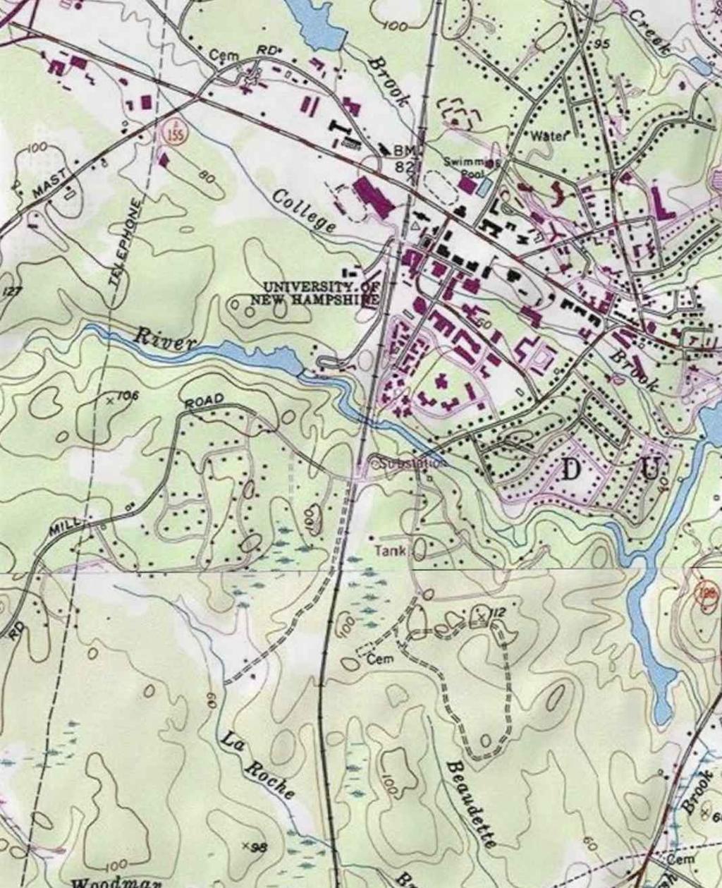
1 APPENDIX A F107 & 380 Lines OYSTER RIVER DURHAM, NH 1. The design and proposed construction of this crossing is shown on the attached PSNH Transmission Business Drawing entitled DOUBLE CKT F107 & 380 BETWEEN STR. 28 & 29 OYSTER RIVER, DURHAM, NEW HAMPSHIRE (Drawing No. F ) marked as Exhibit The location of the double circuit F107 and 380 crossing is shown on the attached Location Plan marked as Exhibit Line F107 and 380 will cross the Oyster River on a 1-pole, direct embed, 110 foot pole (16.5 feet embedded), steel tangent suspension structure (northern side) and on a 1-pole, 100 foot, steel deadend strain structure on concrete foundation (southern side). Details of these structures are shown on Exhibit 1. As shown on Exhibit 1, for Structure 28 the 115kV phase wires have an approximate separation at the structure of 7-15 feet vertically and 0-13 feet horizontally in a delta configuration. The static wire is carried on the structure by a support bracket approximately nine inches down from the top of the structure. The 34.5kV phase wires are arranged horizontally approximately 15 feet below the lowest 115kV conductor and have an approximate separation at the structure of 0-5 feet vertically and 3-6 feet horizontally. The neutral wire is carried on the structure by a support bracket approximately seven feet down below the 34.5kV phase wires. As shown on Exhibit 1, for Structure 29 the 115kV phase wires have an approximate separation at the structure of 7-15 feet vertically and 3-20 feet horizontally in a delta configuration. The static wire is carried on the structure by a support bracket approximately six inches down from the top of the structure. The 34.5kV phase wires are arranged horizontally approximately 16 feet below the lowest 115kV conductor and have an approximate separation at the structure of zero feet vertically and five feet horizontally. The neutral wire is carried on the structure by a support bracket approximately seven feet down below the 34.5kV phase wires. All NESC clearances at the structure, as described in paragraph 11 of the petition, have been met by exceeding the horizontal and/or vertical clearances required. Land along the shoreline between the structures of this crossing and the river is not traversable by vehicles. However, minimum distances to ground per the NESC have been met. A clearance of 24 feet between the neutral and the closest ground point has been provided. This exceeds the NESC required clearance of 15.5 feet by 8.5 feet. As all other phase wires are above this elevation they will always exceed the NESC required clearance. 4. Flood water elevations for the Oyster River were based on information contained in flood insurance rate maps provided by FEMA. Flood elevations are based on FEMA FIRM Map 33017C0314D Panel 314 or 405 dated May 17, 2005 and FEMA FIS Study 33015CV001A Dated May 17, The 10-year flood elevation for this portion 7
2 of the river is approximately 33.3 feet. The area of the crossing, as required by the NESC (Section 232), is approximately 38.1 acres (314 feet x5280 feet/43560sf/acre). As stated in paragraph 10 of the petition, the minimum required 115 kv conductor clearance for water surface areas between acres is 30.1 feet for 115 kv, and 28.5 feet for 34.5 kv. 5. The sags and clearances to the water surface during a 10-year flood event for this crossing are as follows; PSNH has investigated a multitude of weather and loading conditions for its design. PSNH used these design conditions and combinations thereof to determine the minimum clearance of all conductors to the water and land surfaces, between the phase conductors and OPGW cable and neutral conductors. PSNH has determined that the weather cases and combinations listed below result in the minimum clearance and control over all other weather conditions and combinations. Shield wires Due to the fact that the OPGW wire is located above the phase wires, its clearance to the water surface will always exceed the minimum required NESC distance. F107 (115 kv): 285 degrees F Max operating temperature (Phase wires) based on PSNH transmission standards - The maximum conductor sag for this weather case will be 22 feet with a clearance to the water surface of 57.1 feet. This condition produces the greatest sag in the phase wires and therefore the minimum clearance to the water surface. This design will exceed the minimum clearance requirement of 30.1 feet by 27 feet under temporary emergency conditions during a 10-yr storm event. F107 (115 kv): Minimum phase to shield wire(s) clearance The weather case that would produce the minimum clearance between the phase wires and the shield wires would be a combination of winter weather factors. First, the phase wires would have to be at 30 deg. F just after an ice storm and would have just dropped their ice. The shield wires would be at 32 deg. F and would still be iced with 1/2 of radial ice. Under these conditions the clearance would be 12 feet vertically and 6 feet horizontally from the shield wires to the closest phase wire. As described in Paragraph 11 of the petition, 64.7 inches (5.4 feet) of horizontal and/or 32.3 inches (2.7 feet) of vertical clearance is required between 115kV and 0kV conductors. The line would exceed both clearance requirements. F107 and 380 (115kV and 34.5kV): Minimum 115kV phase conductor to 34.5kV phase conductor clearance The weather case that would produce the minimum clearance between the 115kV phase 8
3 wires and the 34.5 kv phase wires would occur when the 34.5kV conductor is at 30 deg. F with no ice and the 115kV phase wires are at their maximum operating temperatures of 285 degrees F. Under these conditions the clearance would be 8.7 feet vertically and 1 foot horizontally from the shield wires to the closest phase wire. As described in Paragraph 11 of the petition, 70.7 inches (5.9 feet) of horizontal and/or 40.7 inches (3.4 feet) of vertical clearance is required between 115kV and 34.5kV conductors. The line design will meet these requirements as the conductors will exceed the vertical requirement by 5.8 feet under worst case conditions. 380 (34.5 kv): 212 degrees F Max operating temperature (Phase wires) based on PSNH distribution standards - The maximum conductor sag for this weather case will be 24 feet with a clearance to the water surface of 36.7feet. This condition produces the greatest sag in the phase wires and therefore the minimum clearance to the water surface. This design will exceed the minimum clearance requirement of 28.5 feet by 8 feet under temporary emergency conditions during a 10-yr storm event. 380 (Neutral): 120 degrees F Max operating temperature (Phase wires) based on PSNH distribution standards - The maximum conductor sag for this weather case will be 21 feet with a clearance to the water surface of 30.3 feet. This condition produces the greatest sag in the phase wires and therefore the minimum clearance to the water surface. This design will exceed the minimum clearance requirement of 25.5 feet by 4.8 feet under temporary emergency conditions during a 10-yr storm event. 380 (Neutral): Minimum phase to neutral clearance Due to the fact that the 115kV phase conductors are located above the 34.5kV phase wires, its clearance to the neutral conductor will always exceed the minimum required NESC distance. The weather case that would produce the minimum clearance between the 34.5kV phase wires and the neutral wire would be a condition where the neutral conductor is at 80 deg. F and the 34.5kV conductors are at their maximum operating temperatures of 212 degrees F. Under these conditions the clearance of the closest 34.5kV line would be 1.5 feet vertically and 0 feet horizontally from the neutral wire to the closest phase wire. As described in Paragraph 11 of the petition, 59.8 inches (4.15 feet) of horizontal and/or 15.7 inches (1.3 feet) of vertical clearance is required between 34.5kV and 0kV conductors. The line design will meet these requirements as the conductors will exceed the vertical requirement by 0.2 feet under worst case conditions. 9
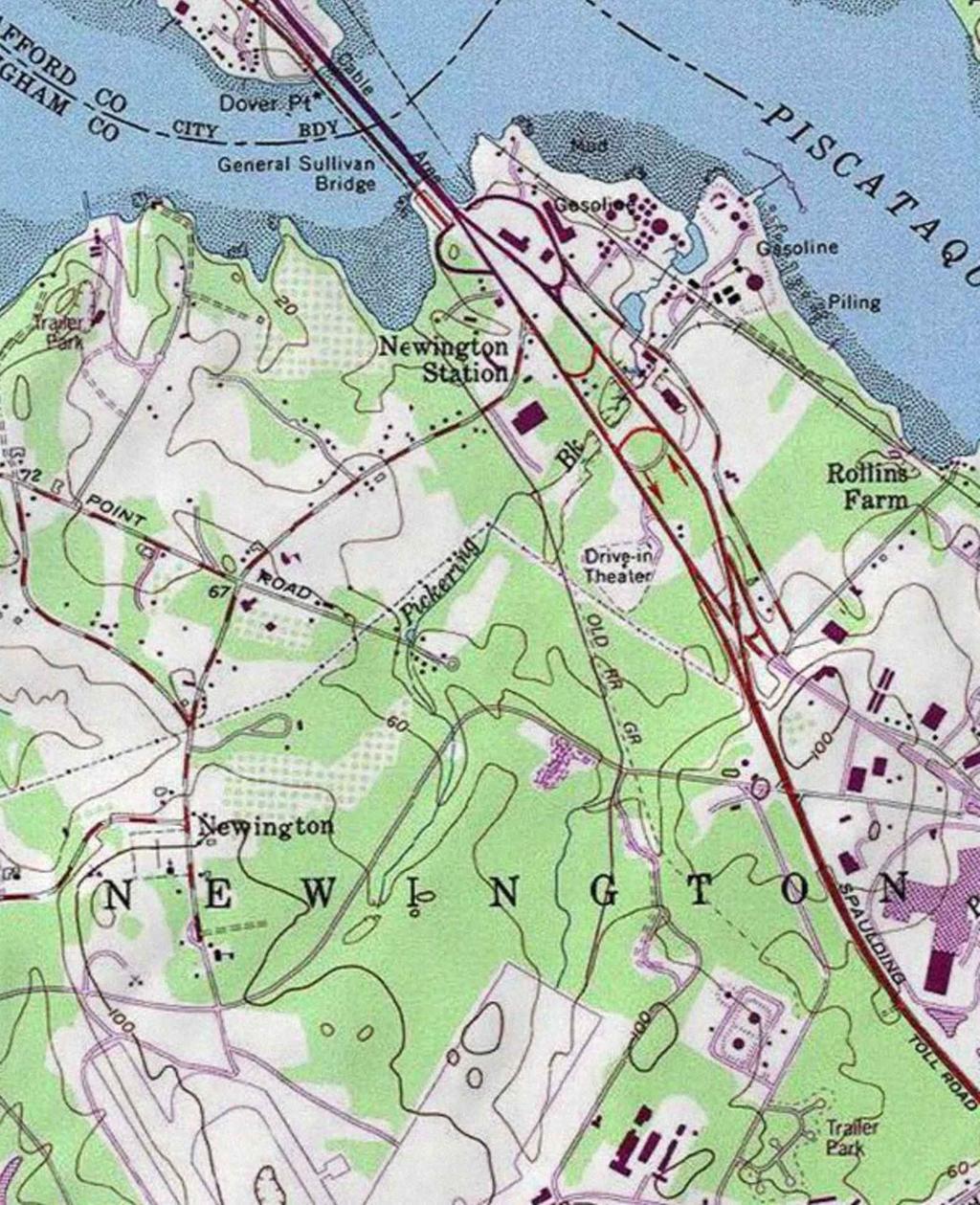
4 APPENDIX B F107 & 3850 Lines PICKERING BROOK NEWINGTON, NH 1. The design and proposed construction of these crossings is shown on the attached PSNH Transmission Business Drawings entitled SINGLE CKT F107 BETWEEN STR. 119 & 120 PICKERING BROOK, NEWINGTON, NEW HAMPSHIRE (Drawing No. F ) marked as Exhibit 3 and SINGLE CKT 3850 BETWEEN STR. 5 & 6 PICKERING BROOK, NEWINGTON, NEW HAMPSHIRE (Drawing No ) marked as Exhibit The location of the single circuit F107 crossing is shown on the attached Location Plan marked as Exhibit 4. The location of the single circuit 3850 crossing is shown on the attached Location Plan marked as Exhibit Line F107 will cross the Pickering Brook on a 1-pole, direct embed, 100 foot pole (16 feet embedded), steel tangent suspension structure (eastern side) and on a 1- pole, 75 foot, steel deadend strain structure on concrete foundation (western side). Details of these structures are shown on Exhibit 3. As shown on Exhibit 3, for Structure 120 the 115kV phase wires have an approximate separation at the structure of 8-15 feet vertically and 0-13 feet horizontally (6.5 foot post insulators) in a delta configuration. The static wire is carried on the structure by a support bracket approximately nine inches down from the top of the structure. As shown on Exhibit 3, for Structure 119 the 115kV phase wires have an approximate separation at the structure of 7-15 feet vertically and feet horizontally in a delta configuration. The static wire is carried on the structure by a support bracket approximately six inches down from the top of the structure. Land along the shoreline between the structures of this crossing and the river is not traversable by vehicles. However, minimum distances to ground per the NESC have been met. A clearance of 26.2 feet between the phase wire and the closest ground point has been provided. This exceeds the NESC required clearance of 20.1 feet by 6.1 feet. As all other phase wires are above this elevation they will always exceed the NESC required clearance. 4. Line 3850 will cross the Pickering Brook on a 1-pole, direct embed, 60 foot pole (eight feet embedded), wood deadend structure (western side) and on a 1-pole, direct embed 60 foot (eight feet embedded), wood tangent structure (eastern side). As shown on Exhibit 5, for Structure 5 the 34.5kV phase wires have an approximate separation at the structure of five feet vertically and 0-9 feet horizontally in a horizontal configuration. The neutral wire is carried on the structure by a support bracket approximately five feet down below the 34.5kV phase wires. As shown on Exhibit 5, for Structure 6 the 34.5kV phase wires have an approximate separation at the structure of four feet eight inches horizontally in a horizontal configuration. The neutral wire is carried on the structure by a support bracket approximately five feet down below the 10
5 34.5kV phase wires. All NESC clearances at the structure as described in paragraph 11 of the petition have been met by exceeding the horizontal and/or vertical clearances required. Land along the shoreline between the structures of this crossing and the river is not traversable by vehicles. However, minimum distances to ground per the NESC have been met. A clearance of 21 feet between the neutral and the closest ground point has been provided. This exceeds the NESC required clearance of 15.5 feet by 5.5 feet. As all other phase wires are above this elevation they will always exceed the NESC required clearance. 5. Flood water elevations for the Pickering Brook were based on information contained in flood insurance rate maps provided by FEMA. There was no flood elevation provided on the FEMA Maps as this portion of Pickering Brook is in the Zone X section of Map 33015C0255E, dated May 17, Zone X locations indicate that under a 100 year flood event the flood depth would be less than 1 foot. For conservative design it was assumed that the water level would not exceed the top of bank during a 10 year flood. The 10-year flood elevation for this portion of the river was designed at approximately 27.7 feet. This far exceeds the 1 foot depth prescribed on the FEMA flood map. The area of the crossing, as required by the NESC (Section 232), is approximately 9.9 acres (82 feet x5280 feet/43560sf/acre). As stated in paragraph 10 of the petition, the minimum required 115 kv conductor clearance for water surface areas between under 20 acres is 22.1 feet for 115 kv and 20.5 feet for 34.5 kv. 6. The sags and clearances to the water surface during a 10-year flood event for this crossing are as follows; PSNH has investigated a multitude of weather and loading conditions for its design. PSNH used these design conditions and combinations thereof to determine the minimum clearance of all conductors to the water and land surfaces, between the phase conductors and OPGW cable and neutral conductors. PSNH has determined that the weather cases and combinations listed below results in the minimum clearance and control over all other weather conditions and combinations. Shield wires Due to the fact that the OPGW wire is located above the phase wires, its clearance to the water surface will always exceed the minimum required NESC distance. F107 (115 kv): 285 degrees F Max operating temperature (Phase wires) based on PSNH transmission standards - The maximum conductor sag for this weather case will be 18.4 feet with a clearance to the water surface of 34.1 feet. This condition produces the greatest sag in the phase wires and therefore the minimum clearance to the water surface. This design will exceed the minimum clearance requirement of 22.1 feet by 12 feet under temporary emergency conditions during a 10-yr storm event. 11
6 F107 (115 kv): Minimum phase to shield wire(s) clearance The weather case that would produce the minimum clearance between the phase wires and the shield wires would be a combination of winter weather factors. First, the phase wires would have to be at 30 deg. F just after an ice storm and would have just dropped their ice. The shield wires would be at 32 deg. F and would still be iced with 1/2 of radial ice. Under these conditions the clearance would be 13.5 feet vertically and 6 feet horizontally from the shield wires to the closest phase wire. As described in Paragraph 11 of the petition 64.7 inches (5.4 feet) of horizontal and/or 32.3 inches (2.7 feet) of vertical clearance is required between 115kV and 0kV conductors. The line would exceed both clearance requirements. 380 (34.5 kv): 212 degrees F Max operating temperature (Phase wires) based on PSNH distribution standards - The maximum conductor sag for this weather case will be 22.1 feet with a clearance to the water surface of 31.9 feet. This condition produces the greatest sag in the phase wires and therefore the minimum clearance to the water surface. This design will exceed the minimum clearance requirement of 20.5 feet by 11.4 feet under temporary emergency conditions during a 10-yr storm event. 380 (Neutral): 120 degrees F Max operating temperature (Phase wires) based on PSNH distribution standards - The maximum conductor sag for this weather case will be 19 feet with a clearance to the water surface of 23.5 feet. This condition produces the greatest sag in the phase wires and therefore the minimum clearance to the water surface. This design will exceed the minimum clearance requirement of 17.5 feet by 6 feet under temporary emergency conditions during a 10-yr storm event. 380 (Neutral): Minimum phase to neutral clearance The weather case that would produce the minimum clearance between the 34.5kV phase wires and the neutral wire would be a condition where the neutral conductor is at 80 deg. F and the 34.5kV conductors are at their maximum operating temperatures of 212 degrees F. Under these conditions the clearance of the closest 34.5kV line would be 2.4 feet vertically and 0 feet horizontally from the neutral wire to the closest phase wire. As described in Paragraph 11 of the petition, 49.8 inches (4.15 feet) of horizontal and/or 15.7 inches (1.3 feet) of vertical clearance is required between 34.5kV and 0kV conductors. The line design will meet these requirements as the conductors will exceed the vertical requirement by 1.1 feet under worst case conditions. 12
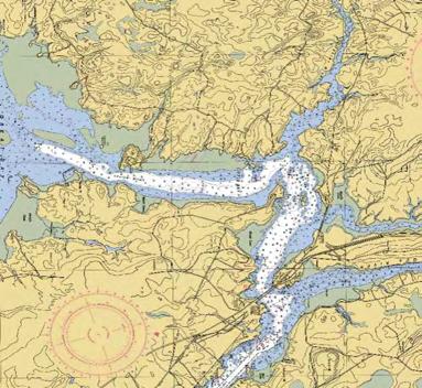
7 APPENDIX C F107 Line Little Bay Durham, NH and Newington, NH 1. The design and proposed construction of this crossing is shown on the attached PSNH Transmission Business Drawing entitled F107 LINE CROSSING, LITTLE BAY DURHAM AND NEWINGTON, NEW HAMPSHIRE (Drawing No. F ) marked as Exhibit The location of the F107 crossing of Little Bay is also shown on Exhibit Line F107 will cross Little Bay using three underground submarine cables. The three cables will be buried using a water jet plow, driver hand jetting or mechanical trenching. The submarine cable will begin at F107 Structure 101 on the West shore of Little Bay. This structure will be a single pole, 80 foot, steel deadend strain structure on concrete foundation. The cable will then run underwater to an underground manhole on the East shore of Little Bay. Details of Structure 101 are provided with the petition on Exhibit 7. As shown on Exhibit 7, for Structure 101 the overhead 115kV phase wires have an approximate separation at the structure of 6 to 12 feet vertically and 0 to 20 feet horizontally in a delta configuration. The static wire is carried on the structure by a support bracket approximately 9 inches down from the top of the structure on the left and right poles. The submarine cable will run down the pole at Structure 101 and be buried to a depth of 42 inches heading east for approximately 367 feet by open trenching or diver burial, one phase per pole, from the overhead conductor elevation. The cables will then proceed 1835 feet at 42 inch burial using a water jet plow. At that point the depth will be increased to 8 feet depth in the main channel for approximately 2431 feet. Continuing the Eastern path, the depth will decrease to 42 inches for the last 770 feet where the cable will come on shore and enter an underground splice vault. From that point the submarine cable will be spliced to a land based underground cable to connect to the above ground portion of the line at Structure 102. Details of the splice vault have been included on Exhibit 7. As shown on Exhibit 7 the cables will be installed 42 inches below finished grade and will be spaced a minimum of 18 inches apart vertically attached to the side of the manhole. All NESC clearances at the structure, as described in paragraph 11 of the petition, have been met by exceeding the horizontal and/or vertical clearances required. This crossing will be entirely underground or underwater so all overhead clearances described will not be applicable to this crossing. 4. The underwater crossing will consist of three 115kV rated, 1400 mm 2 XLPE submarine cables. The cable will have a copper wire core surrounded by extruded XLPE insulation. A layer of copper armoring will be installed on the outside of the cable to provide mechanical protection. The overall cable diameter will be approximately mm. The cables will be installed with a separation of approximately 30 feet in the main channel of Little Bay. As they approach land the will converge to within 5 feet separation. Two ADSS fiber optic cables will be strapped to two separate cable (one 13
8 ADSS cable per conductor cable) to continue the fiber optic path for the F107 line. These cables will follow the same route as the 115kV conductors. There are four existing cables in the corridor that have been abandoned. Some of these cables may be raised to the surface, cut, capped and reset on the bottom to move them out of the way of the new cable installation. 5. The submarine cable will be buried between 42 inches and 96 inches depending on the location within the Little Bay. This will meet or exceed the NESC clearance of 42 inches based on Table of the NESC for underground direct bury cable over 50kV. Section 351.C.5 of the NESC also states that Submarine crossings should be routed, installed, or both, so they will be protected from erosion by tidal action or currents. They should not be located where ships normally anchor. All three cables will be located in an existing cable crossing location as shown on the NOAA Navigational Chart for Little Bay and Great Bay attached to this petition as Exhibit 8. Per the NOAA Nautical Chart User s Manual dated 1997 this designation includes restrictions on anchoring in the cable area. This satisfies the requirement of the NESC. The cables will also be buried to protect them from tidal action as well as any inadvertent boat anchors. 6. The underground vault will comply with all requirements of the NESC. As described in NESC Section 323.A, the underground vault will be designed for an HS- 20 vehicle loading. Per NESC Section 323.B, the underground vault will have a vertical dimension not less than 6 feet and a minimum of 3 feet of working space and shall be accessible by two manholes with a minimum diameter of 26 inches. 14
9 GRAPHIC SCALE
10
11 GRAPHIC SCALE
12
13 GRAPHIC SCALE
14


15 PLAN VIEW LOCUS PROFILE VIEW 500 1: Feet Caldwell Marine International, LLC.

16 LOCATION OF CHARTED CABLE AREA. APPROXIMATELY 1000 FEET WIDE EXHIBIT 8
CS10 # Network Safety Performance Objectives (2016)
") CS10 #4384287 Network Safety Performance Objectives (2016) Context & Purpose The Horizon Power Network Safety Objectives (2016) (Objective Statement) has been prepared for each of network safety performance
CS10 #4384287 Network Safety Performance Objectives (2016) Context & Purpose The Horizon Power Network Safety Objectives (2016) (Objective Statement) has been prepared for each of network safety performance
I. Purpose... 1 II. Introduction... 2 III. General and Safety Precautions... 2 IV. Reference Documents... 3 V. Installation Overview...
 Figure 8 Cable Installation Guideline TABLE OF CONTENTS I. Purpose.... 1 II. Introduction... 2 III. General and Safety Precautions... 2 IV. Reference Documents... 3 V. Installation Overview... 4 A. Methods...
MV-105 MEDIUM VOLTAGE CABLE. 5kV, 8kV, 15kV, 25kV & 35kV
 MV-05 MEDIUM VOLTAGE CABLE 5kV, 8kV, 5kV, 5kV & 5kV MV-05 MEDIUM VOLTAGE POWER CABLE 5kV % INSULATION LEVEL 8kV 00% INSULATION LEVEL Conductor conforming to ASTM B and Class B Compact stranded in accordance
KMU SUBSTATION WORKSHOP
 Rick Aguilar, Director of Job Training & Safety KMU SUBSTATION WORKSHOP JUNE 29-30, 2016 OTTAWA, KS Hazards & Safety Rules Qualified Personnel & Task-Based Hazard Mitigation Worksite Applications & Considerations
Swimming Pool Requirements
 Swimming Pool Requirements 8040 S. 6th Street Oak Creek, WI 53154 (414) 766-7000 www.oakcreekwi.org Revised: August 8. 2017 PERMITS A permit from the Inspection Department is required prior to putting
Methods of installation of ADSS fiber optic cables
 Methods of installation of ADSS fiber optic cables Two main methods recommended by the cable manufacturers: A. Mobile Cable Reel method generally recommended for span < 50 m B. Static Cable Reel method
Hydraulic Modeling Analysis
 Final Report Photograph: http://www.newington-dover.com Newington to Dover, New Hampshire Prepared for: Vanasse Hangen Brustlin, Inc. 6 Bedford Farms Drive, Suite 607 Bedford, New Hampshire 03110-6532
SWIMMING POOL REQUIREMENTS
 PERMITS A permit from the Inspection Department is required prior to putting up a permanent pool. A permit is required for permanent pools, such as the following: SWIMMING POOL REQUIREMENTS The pool is
TOWN of CHEEKTOWAGA Permit Application for Swimming Pools, Hot Tubs, or Personal Spas
 Permit Application for Swimming Pools, Hot Tubs, or Personal Spas / 20 - Date of Application Received By Permit No. APPLICANT to COMPLETE the PINK PORTION! ( ) ( ). Applicant s Name Daytime Phone No. Cell
Page 1 of 1 04/19/13 SBR
 Office of Roadway Engineering - Plan Insert Sheets Number Title Date Number Title Date Number Title Date 201015 Extension of Anchor Bolts 07/20/12 207000 Bikeway Pavement Marking Details 01/18/13 202010
COMMONWEALTH OF MASSACHUSETTS ENERGY FACILITIES SITING BOARD DEPARTMENT OF PUBLIC UTILITIES NOTICE OF ADJUDICATION NOTICE OF PUBLIC COMMENT HEARING
 COMMONWEALTH OF MASSACHUSETTS ENERGY FACILITIES SITING BOARD DEPARTMENT OF PUBLIC UTILITIES NOTICE OF ADJUDICATION NOTICE OF PUBLIC COMMENT HEARING EFSB 17-05/D.P.U. 18-18/18-19 Vineyard Wind LLC Notice
Part 3: Safety Rules for the Installation and Maintenance of Underground Electric Supply and Communication Lines
 Part 3: Safety Rules for the Installation and Maintenance of Underground Electric Supply and Communication Lines Charles Bleakley Chair, Subcommittee 7 PART 3 UNDERGROUND LINES 2 313. Inspection and tests
INSTALLATION PROCEDURE FOR OPGW FIBER OPTIC CABLES
 Page 1 of 15 INSTALLATION PROCEDURE FOR OPGW FIBER OPTIC CABLES Page 2 of 15 1. PURPOSE 2. SCOPE 3. REFERENCES 4. GENERAL INDEX 5. PROCEDURES 5.1 Line survey 5.2 Transport, loading, unloading and storage
22. Specialty Valves.
 22. Specialty Valves. a. Types of Specialty Valves. 1) Use of the following specialty valves is covered in this section: Altitude Valve, Pressure Reducing Valve, Pressure Relief Valve, Swing Check Valve,
Appendix J: Q1-Highway 35 Route Construction Plan
 PSC REF#:150055 Wisconsin CPCN Appendix J Appendix J: Q1-Highway 35 Route Construction Plan Public Service Commission of Wisconsin RECEIVED: 06/29/11, 8:51:24 AM Hampton Rochester La Crosse 345 kv Transmission
S Surge Arresters
 Surge Arresters UltraSIL Polymer-Housed VariSTAR Type US, UH, and UX Station-Class Surge Arresters Installation and Maintenance Instructions Service Information S235-88-1 Contents Product Information...........................1
City of Roseville Section 13 Design Standards. _Bikeways January 2016 SECTION 13 BIKEWAYS
 SECTION 13 BIKEWAYS 13-1 GENERAL The City of Roseville bikeway standards are designed to insure that transportation and recreational bikeways are constructed in a manner that would provide a safe and comfortable
Item 404 Driving Piling
 Item Driving Piling 1. DESCRIPTION Drive piling. 2. EQUIPMENT 2.1. Driving Equipment. Use power hammers for driving piling with specified bearing resistance. Use power hammers that comply with Table 1.
PERMANENT POOLS. Location
 Community Development Department 211 Walnut Street - PO Box 426 Neenah, WI 54957-0426 Phone: (920) 886-6130 Fax: (920) 886-6129 Web site: www.ci.neenah.wi.us PERMANENT POOLS A pool is any man-made structure,
Pole Foundation Design with Spreadsheet
 PDHonline Course S235 (1 PDH) Pole Foundation Design with Spreadsheet Instructor: John W. Andrew, PE 2012 PDH Online PDH Center 5272 Meadow Estates Drive Fairfax, VA 22030-6658 Phone & Fax: 703-988-0088
Summary of Architecture Parallel Session. G. Hallewell/CPP Marseille P. Piattelli/ LNS Catania
 Summary of Architecture Parallel Session G. Hallewell/CPP Marseille P. Piattelli/ LNS Catania Parallel Session A1.2: Architecture: First session mainly devoted to undersea connectivity Chair: G. HALLEWELL,
Swimming Pool Permit and Inspection Requirements
 Fred Gibbs, Director 3300 Corinth Parkway First Floor Corinth, TX 76208 Corinth Planning & Development Ph: 940-498-3273 https://www.cityofcorinth.com/141/planning-development Swimming Pool Permit and Inspection
RESIDENTIAL SWIMMING POOLS AND SPAS A GUIDE FOR HOMEOWNERS
 RESIDENTIAL SWIMMING POOLS AND SPAS A GUIDE FOR HOMEOWNERS City of Redding 777 Cypress Avenue Redding CA 96001 Telephone: (530) 225-4013 FAX: (530) 225-4360 A Swimming Pool is any body of water 18 inches
Fortified For Safer Living
 Fortified For Safer Living Module 15: Protecting Homes Against Floods and Storm Surge An important part of trying to reduce the damage and losses from storm events is to make sure that the home doesn t
Excavations and Trenches
 Purpose Excavation and trenching are among the most hazardous work activities undertaken by the TNRD. This document outlines general requirements and specific safe work procedures to ensure the health
Check with local zoning official for property line distance requirements.
 RESIDENTIAL POOL PLAN SUBMITTAL GUIDELINES The following guidelines are intended to assist municipal residents with the permit acquisition process with regard to pools, spas and hot tubs for single family
ELECTRICAL (COMPREHENSIVE) SAFETY PROGRAM REGULATORY STANDARD: OSHA - 29 CFR CFR , ,
 SAFETY PROGRAM REGULATORY STANDARD: OSHA - 29 CFR CFR , ,") ELECTRICAL (COMPREHENSIVE) SAFETY PROGRAM REGULATORY STANDARD: OSHA - 29 CFR 1910.331 335-29 CFR 1926.302, 1926.416, 1926.417 BASIS: The National Safety Council estimates that there are at least 300 deaths
ELECTRICAL (COMPREHENSIVE) SAFETY PROGRAM REGULATORY STANDARD: OSHA - 29 CFR 1910.331 335-29 CFR 1926.302, 1926.416, 1926.417 BASIS: The National Safety Council estimates that there are at least 300 deaths
POOL AND HOT TUB/SPA REGULATIONS A BUILDING PERMIT IS REQUIRED BEFORE THE INSTALLATION OF A POOL.
 CITY OF NEENAH Department of Community Development (Inspection Department) 211 Walnut Street Phone (920) 886-6130 website: www.ci.neenah.wi.us POOL AND HOT TUB/SPA REGULATIONS A BUILDING PERMIT IS REQUIRED
SPEED SHORE MANUFACTURER S TABULATED DATA "MHS" MODELS. STEEL MANHOLE SHIELDS 4 Single Wall 4 Double Wall 4 Double Wall with Cut-Outs
 SPEED SHORE MANUFACTURER S TABULATED DATA "MHS" MODELS STEEL MANHOLE SHIELDS 4 Single Wall 4 Double Wall 4 Double Wall with Cut-Outs January 01, 2005 3330 S. SAM HOUSTON PKWY E. HOUSTON, TEXAS 77047 Tel:
THE CORPORATION OF THE TOWN OF GREATER NAPANEE BY-LAW NO
 THE CORPORATION OF THE TOWN OF GREATER NAPANEE BY-LAW NO. 98-42 Being a By-law prescribing the height and description of, and the manner of erecting and maintaining fences and gates around privately owned
HURRICANE SANDY LIMITED REEVALUATION REPORT UNION BEACH, NEW JERSEY DRAFT ENGINEERING APPENDIX SUB APPENDIX D SBEACH MODELING
 HURRICANE SANDY LIMITED REEVALUATION REPORT UNION BEACH, NEW JERSEY DRAFT ENGINEERING APPENDIX SUB APPENDIX D SBEACH MODELING Rev. 18 Feb 2015 1 SBEACH Modeling 1.0 Introduction Following the methodology
DESIGN CRITERIA DIVISION 4900 TRAFFIC SIGNALS
 DESIGN CRITERIA DIVISION 4900 TRAFFIC SIGNALS 4901 GENERAL: These criteria shall be adhered to for the design of all publiclyfinanced or privately-financed traffic signal systems to be installed in the
: Electric Power Generation, Transmission, and Distribution. Region IV - OSHA
 1910.269: Electric Power Generation, Transmission, and Distribution Region IV - OSHA Scope This standard covers the operation and maintenance of electric power generation, control, transformation transmission,
Evaluation of June 9, 2014 Federal Emergency Management Agency Flood Insurance Study for Town of Weymouth, Norfolk, Co, MA
 Evaluation of June 9, 2014 Federal Emergency Management Agency Flood Insurance Study for Town of Weymouth, Norfolk, Co, MA Prepared For: Woodard & Curran 95 Cedar Street, Suite 100 Providence, RI 02903
Intermediate Angle, 0-25, Drilling detail. Angle 26-50, Baulk Plates, Pole Details. Termination Poles, ABC Details
 Part 7 LVABC Overhead Drawing Register Number A1 A2 A3 A4 A5 A6 A8 A9 Description Intermediate Angle, 0-25, Drilling detail Angle 26-50, Baulk Plates, Pole Details Termination Poles, ABC Details Inline
VISUAL AIDS FOR DENOTING OBSTACLES
 CHAPTER 6. VISUAL AIDS FOR DENOTING OBSTACLES 6.1 Objects to be marked and/or lighted Note.C The marking and/or lighting of obstacles is intended to reduce hazards to aircraft by indicating the presence
RESIDENTIAL SWIMMING POOL REQUIREMENTS
 CITY OF GRANDVIEW / BUILDING SERVICES 1200 MAIN STREET, GRANDVIEW, MO 64030 PHONE: (816) 316-4817 FAX: (816) 316-4809 WWW.GRANDVIEW.ORG RESIDENTIAL SWIMMING POOL REQUIREMENTS Community Development Department
TECHNICAL BULLETIN PINPOINT CONDUIT COUPLING AND SPLICING RECOMMENDATIONS
 TECHNICAL BULLETIN PINPOINT CONDUIT COUPLING AND SPLICING RECOMMENDATIONS CONTENTS: 1.0 General Information 2.0 Preparation and Splicing of PinPoint Wire 3.0 PinPoint Direct Bury Splice Kit Specifications
Permit and Inspection Requirements for Swimming Pools
 Permit and Inspection Requirements for Swimming Pools Building Inspection Office (817) 503.1030 City of Colleyville 100 Main Street Colleyville, TX 76034 Inspection Request Line (817) 503.1172 Building
STRUCTURE S-65 PURPOSE SPILLWAY OPERATION
 STRUCTURE S-65 This structure is a reinforced concrete, gated spillway with discharge controlled by three cable operated, vertical lift gates, and a reinforced concrete lock structure with two pairs of
SWIMMING POOLS CHAPTER 41
 CHAPTER 41 SWIMMING POOLS SECTION E4101 GENERAL E4101.1 Scope. The provisions of this chapter shall apply to the construction and installation of electric wiring and equipment associated with all swimming
Pool / Hot Tub Permit
 Application Date: Pool / Hot Tub Permit Lower Southampton Township 1500 Desire Avenue, Feasterville, Pa 19053 215-357-7300 Permit Number: Permit Fee: Fee includes required fencing permit and bonding fee.
City of Crystal Lake Community Development Department
 City of Crystal Lake Community Development Department 100 W. Woodstock Street Crystal Lake, IL 60014 www.crystallake.org Phone (815) 356-3605 Fax (815) 479-1647 building@crystallake.org ABOVE GROUND SWIMMING
Residential Swimming pools
 City of Republic Community Development Department Residential Swimming pools REVISION DATE: JANUARY 2017 Swimming Pool Safety Definitions: Barrier Requirements: A) Application All swimming pools over 24
Figure 4, Photo mosaic taken on February 14 about an hour before sunset near low tide.
 The Impact on Great South Bay of the Breach at Old Inlet Charles N. Flagg and Roger Flood School of Marine and Atmospheric Sciences, Stony Brook University Since the last report was issued on January 31
New Orleans Municipal Yacht Harbor
 New Orleans Municipal Yacht Harbor Marina Schematic Design Update 601 Poydras St., Suite 1860 New Orleans, LA, 70130 504-648-3560 Post-Katrina Municipal Yacht Harbor: Introduction The MYH was an approximate
Work Standard CABLE PULLING OPERATIONS
 Page 1 of 19 ****This document supercedes BECo WMS 2.9-1.1**** 1.0 Purpose CABLE PULLING OPERATIONS 1.1 This Work Method Standard prescribes the preferred methods of removing and installing cables between
Protection for Vessels Engaged in Servicing Submarine Cables
 Protection for Vessels Engaged in Servicing Submarine Cables Proposed Amendments to COLREGS Brief to Navigation Safety Advisory Council November 28, 2012 Tampa, FL Dr. Ronald J. Rapp TE SubCom and Representing
Safety Policy and Procedure
 Safety Policy and Procedure Policy Number 004 Authorized By: The Cianbro Companies Alan Burton Title: Excavation Safety Effective Date: 01/01/75 Page 1 of 16 1 Status 1.1 Update of existing policy, effective
STAKING TRAFFIC CONTROL SIGNAL SYSTEMS
 Locating the components of a traffic control signal is not an exact science; many factors influence the location of the components. These factors include: lane widths, radii, pedestrian curb ramp requirements,
TEPZZ 9_ 9 A_T EP A1 (19) (11) EP A1 (12) EUROPEAN PATENT APPLICATION. (43) Date of publication: Bulletin 2015/36
 (11) EP A1 (12) EUROPEAN PATENT APPLICATION. (43) Date of publication: Bulletin 2015/36") (19) TEPZZ 9_ 9 A_T (11) EP 2 913 293 A1 (12) EUROPEAN PATENT APPLICATION (43) Date of publication: 02.09.2015 Bulletin 2015/36 (51) Int Cl.: B66D 1/38 (2006.01) (21) Application number: 15250003.9 (22)
(19) TEPZZ 9_ 9 A_T (11) EP 2 913 293 A1 (12) EUROPEAN PATENT APPLICATION (43) Date of publication: 02.09.2015 Bulletin 2015/36 (51) Int Cl.: B66D 1/38 (2006.01) (21) Application number: 15250003.9 (22)
Change Crossarm Insulator with Hotsticks
 Change Crossarm Insulator with Hotsticks S T U D E N T M A N U A L March 31, 2005 2 STUDENT TRAINING MANUAL Prerequisites: Introduction to Hotsticks module Use and Care of Hotsticks module Weights & Forces
Field Instruction. Protect Horizon Power employees and contractors from a potential hazard.
 2.15 Temporary Safety Barriers and/or Warning Signs Purpose This instruction sets out the minimum requirements for the installation and erection of temporary safety barriers and/or warning signs to: Protect
Striking an underground pipeline or underground electric line can lead to serious injury or death. If you hit either, call (800) , even if
 , even if") 1 Striking an underground pipeline or underground electric line can lead to serious injury or death. If you hit either, call (800) 477-5050, even if there is no apparent damage. Call 911 if gas is blowing
1 Striking an underground pipeline or underground electric line can lead to serious injury or death. If you hit either, call (800) 477-5050, even if there is no apparent damage. Call 911 if gas is blowing
HV Spiker Kit - CSTE. 30 th April 2014
 HV Spiker Kit - CSTE 30 th April 2014 Safety Working With Cables As a cable jointer, safety is paramount when working daily with live electricity. When working with cables it is essential to know whether
Chapter 11. Culverts and Bridges Design Checklist for Culvert Design
 Yes No N/A Design Requirements I. GENERAL DESIGN GUIDELINES Chapter 11. Culverts and Bridges A. Culvert design is in accordance with the Culverts chapter of Volume 2 of the UDFCD Manual for additional
Installation Guideline for Placing Fiber Optic Cable into an Underground Duct
 Installation Guideline for Placing Fiber Optic Cable into an Underground Duct Table of Contents A. Purpose... 1 B. Introduction...2 C. General Precautions...2 D. Reference Documents...3 E. Fiber Optic
APPENDIX D-2. Sea Level Rise Technical Memo
 APPENDIX D-2 Sea Level Rise Technical Memo 2185 N. California Blvd., Suite 500 Walnut Creek, CA 94596 (925) 944-5411 Fax: (925) 944-4732 www.moffattnichol.com DRAFT MEMORANDUM To: From: Neil Nichols,
"STEEL FRAMED" ALUMINUM PANEL SHIELDS
 "STEEL FRAMED" ALUMINUM PANEL SHIELDS MANUFACTURE S TABULATED DATA 3330 S. Sam Houston Pkwy Houston, Texas 77047 (713)943-0750 USA Toll Free 1-800-231-6662 Fax (713)943-8483 Www.speedshore.com PRINTED
CHAPTER 8 STAKING SIGNALS AND LIGHTING FIELD GUIDE. 8.1 Staking Traffic Control Signal Systems
 CHAPTER 8 STAKING STAKING Correct staking of traffic control signal or lighting systems is critical to the appropriate placement of system components. 8.1 Traffic Control Signal Systems Locating the components
PLACEMENT OF SIGNS RECOMMENDED PRACTICES SUB-SECTION
 Page 1 of 6 RECOMMENDED PRACTICES PART SECTION SUB-SECTION HIGHWAY SIGNS GENERAL General Proper positioning of signs is an important element in the overall control of traffic within a roadway network.
Anchorage Of Floating Bridges
 Chapter 8. Anchorage Of Floating Bridges Each of these factors must be considered when deciding upon the type of anchorage sys- tem to be installed. Generally, the velocity of the river and the river bottom
REVISED SILT CURTAIN DEPLOYMENT PLAN
 Contract No.: HY/2009/11 Central Wanchai Bypass, North Point Reclamation REVISED SILT CURTAIN DEPLOYMENT PLAN Name Prepared by: China Harbour Engineering Co., Ltd. China Road and Bridge Corporation Joint
TVPPA Lineman Apprenticeship Program
 Self-Study Modules Unit 1 Unit 2 Unit 3 Unit 4 Lineman Apprenticeship Program Skills Labs Pre-Apprentice Assessment Digger Derrick Training Fundamentals Lab 1 Construction Lab 2 Operations Lab 3 Underground
Applications and Considerations Section 11
 11 Applications and Considerations Section 11 www.hubbellpowersystems.com E-mail: hpsliterature@hps.hubbell.com Phone: 573-682-5521 Fax: 573-682-8714 210 North Allen Centralia, MO 65240, USA Copyright
POOL BARRIER AMENDMENTS & GUIDELINES: APPENDIX G SWIMMING POOLS, SPAS AND HOT TUBS
 SECTION AG101 - GENERAL POOL BARRIER AMENDMENTS & GUIDELINES: APPENDIX G SWIMMING POOLS, SPAS AND HOT TUBS AG101.1 General. The requirements of this appendix shall apply to the design and construction
SWIMMING POOL, SPA, & HOT TUB GUIDELINES
 SWIMMING POOL, SPA, & HOT TUB GUIDELINES A. Adopted construction codes and installation requirements 1. 2015 edition of the International Residential Code and Appendix Q, 2. 2014 edition of the National
DISTRIBUTION: Electronic Recipients List TRANSMITTAL LETTER NO. (13-01) MINNESOTA DEPARTMENT OF TRANSPORTATION. MANUAL: Road Design English Manual
 MINNESOTA DEPARTMENT OF TRANSPORTATION. MANUAL: Road Design English Manual") DISTRIBUTION: Electronic Recipients List MINNESOTA DEPARTMENT OF TRANSPORTATION DEVELOPED BY: Design Standards Unit ISSUED BY: Office of Project Management and Technical Support TRANSMITTAL LETTER NO.
DISTRIBUTION: Electronic Recipients List MINNESOTA DEPARTMENT OF TRANSPORTATION DEVELOPED BY: Design Standards Unit ISSUED BY: Office of Project Management and Technical Support TRANSMITTAL LETTER NO.
COOPER POWER. SERIES VariSTAR type AZE station class surge arresters installation and maintenance instructions. Surge Arresters MN235022EN 0.
 Surge Arresters MN235022EN Effective November 2016 Supersedes July 2011 (S235-87-1) COOPER POWER SERIES VariSTAR type AZE station class surge arresters installation and maintenance instructions 0.5 0.866
MODULAR ALUMINUM PANEL SHIELDS MAPS
 MODULAR ALUMINUM PANEL SHIELDS MAPS 3330 S. SAM HOUSTON PKWY E. HOUSTON, TEXAS 77047 Phone: 713.943.0750 Toll Free: 800.231.6662 Fax: 713. 943.8483 April 16, 2009 MODULAR ALUMINUM PANEL SHIELDS Page 2
$ Plan Review Fee when Permit Application is submitted HOT TUBS AND SPAS BUILDING PERMIT APPLICATION. COST: $80.
 Community Development 1050 W Romeo Rd, Romeoville, IL 60446-1530 (815) 886-7200 Fax #: (815) 886-2724 Email: buildinginspections@romeoville.org HOT TUBS AND SPAS BUILDING PERMIT APPLICATION Application
Point LaBarbe/McGulpin Point Response April 2 May 8, 2018 Regional Response Team 3 Meeting November, 2018
 Point LaBarbe/McGulpin Point Response April 2 May 8, 2018 Regional Response Team 3 Meeting November, 2018 TJ Mangoni District Response Advisory Team Supervisor Ninth Coast Guard District 216-214-4285 Summary
Recommendations for Marking Communication Facilities
 Recommendations for Marking Communication Facilities with the Use of 3M EMS Electronic Markers Revised June 21, 2005 Page 1of 12 1.0 Overview The 3М TM electronic marker system is intended to make the
City of DuBois PERMIT APPLICATION P. O. Box 408, 16 West Scribner Ave - DuBois, PA Phone: Fax:
 City of DuBois PERMIT APPLICATION P. O. Box 408, 16 West Scribner Ave - DuBois, PA. 15801 Phone: 814-371-2000 Fax: 814-375-2307 Permit No. LOCATION OF PROPOSED WORK OR IMPROVEMENT Municipality: Tax Parcel
1 Exam Prep OSHA Federal Safety and Health Regulations Questions and Answers
 1 Exam Prep OSHA Federal Safety and Health Regulations Questions and Answers 1. According to O.S.H.A. Safety and Health Regulations, the minimum distance between the side rails of all portable ladders
Dry Hydrants. The installation of a non-pressurized pipe system into local water sources provides a ready means of supplying water to fire engines.
 Dry Hydrants What is a Dry Hydrant? A dry hydrant is a non-pressurized pipe system permanently installed in existing lakes, ponds and streams that provides a suction supply of water to a fire department
CPCS renewal test factsheet
 CPCS renewal test factsheet Introduction to the CPCS renewal test The industry-led CPCS Management Committee has determined that key safety-related knowledge must be checked on each category prior to the
We re good at what we do! Anywhere, TX SITE
 2224 East 39 th Street North Sioux Falls, SD 57104 (800).653.3392 605.332-7833 fax We re good at what we do! SURFACE ANCHOR INSPECTION FOR ABC COMMUNICATION S Anywhere, TX SITE This is an actual inspection
STEEL TRENCH SHIELDS TUFF-LITE MODELS
 STEEL TRENCH SHIELDS TUFF-LITE MODELS 3330 S. SAM HOUSTON PKWY E. HOUSTON, TEXAS 77047 Phone: 713.943.0750 Toll Free: 800.231.6662 Fax: 713. 943.8483 April 16, 2009 TRENCH SHIELDS TUFF-LITE TM Page 2 of
The purpose of this brochure is to explain to owners and contractors the City of Burnaby s requirements for private swimming pools.
 Building Information BURNABY PLANNING & BUILDING DEPARTMENT Swimming Pools The purpose of this brochure is to explain to owners and contractors the City of Burnaby s requirements for private swimming pools.
Swimming Pool Permits are About Health and Safety
 Swimming Pool Permits are About Health and Safety Swimming Pool Booklet Published 2004 Revised 04/06/16 Permitting Department 80 W. Baltimore Street Hagerstown, Md. 21740 240-313-2460 (F) 240-313-2461
Geometric Design Tables
 Design Manual Chapter 5 - Roadway Design 5C - Geometric Design Criteria 5C-1 Geometric Design Tables A. General The following sections present two sets of design criteria tables - Preferred Roadway Elements
Recommendations for Marking Gas Facilities Using 3M EMS Electronic Markers
 Recommendations for Marking Gas Facilities Using 3M EMS Electronic Markers Ball Marker Near-Surface Marker A small marker which is well-suited for bore holes in concrete or asphalt for marking flush-mount
Consult with manufacturers concerning permeation of the pipe walls, jointing materials, valve seats, etc.
 Design Manual Chapter 4 - Water Mains 4C - Facility Design 4C-1 Facility Design A. General Water mains and appurtenances, including hydrants and valves, should be provided along all streets including connections
Risk Control at United Fire Group
 In the United States, falls are the leading cause of fatalities on a construction site. Employers and employees need to do the following: Where protection is required, select fall protection systems appropriate
TECHNICAL MEMORANDUM 002 EMORANNO. 001
 TECHNICAL MEMORANDUM 002 EMORANNO. 001 To: Jack Synder, P.E. EES Consulting From: Mort McMillen, P.E. Paul Larson, SE Date: October 13, 2010 Project: Cc: Taylor Bowen Subject: Technical Memorandum (TM)
GLOBAL CORAL REEF ALLIANCE A non-profit organization for protection and sustainable management of coral reefs
 GLOBAL CORAL REEF ALLIANCE A non-profit organization for protection and sustainable management of coral reefs Global Coral Reef Alliance, 37 Pleasant Street, Cambridge, MA 02139, USA Telephone: 617-864-4226
O-Calc Pro Sag Tension Calculations Explained
 O-Calc Pro Sag Tension Calculations Explained This document is a primer that explains how O-Calc Pro software system handles the tension and sags on cables that are attached to a pole. The document is
APPLICANT: Pacific Northwest National Laboratory Attention: Mr. Charles Brandt 1529 West Sequim Bay Road Sequim, Washington 98382
 US Army Corps of Engineers Seattle District Joint Public Notice Application for a Department of the Army Permit and a Washington Department of Ecology Water Quality Certification and/or Coastal Zone Management
Charlottetown Marine Terminal Pipeline Decommissioning Project Description
 Charlottetown Marine Terminal Pipeline Decommissioning Project Description 69 Marr Road Unit B Rothesay NB, E2E 3J9 Tel (506) 848-1920 Fax (506) 848-1929 Charlottetown Marine Terminal Pipeline Decommissioning
APPENDIX C VEGETATED EMERGENCY SPILLWAY. VERSION 1.0 March 1, 2011
 APPENDIX C VEGETATED EMERGENCY SPILLWAY VERSION 1.0 March 1, 2011 [NOTE: Could use a better photo more clearly showing the emergency spillway in the context of the dam.] SECTION C-1: DESCRIPTION OF PRACTICE
Chapter 5 Site Considerations and Set-ups Table of Contents
 WI-750-074 Rev C Page 1 of 9 Chapter 5 Site Considerations and Set-ups Table of Contents 1. PURPOSE... 1 2. SCOPE... 2 3. DEFINITIONS... 2 4. ASSOCIATED DOCUMENTS... 2 5. SITE CONSIDERATIONS... 2 5.1.
Design Overview. Section 4 Standard Plans for Design. Pedestrian Access Routes. Pedestrian Access Routes. Overview. Cross Slope
 Design Overview Section 4 Standard Plans for Design Fall, 2017 Ann Johnson, PE Services Brady Rutman, SRF Consulting Group Overview Design Basics Recommendations: The Zone System Driveway Crossings Pedestrian
LAMINATED POLES. engineered to solve problems. Coastal Douglas-fir. Field Raked and Tangent Poles
 Coastal Douglas-fir Field Raked and Tangent Poles LAMINATED POLES engineered to solve problems 1 Design Criteria Submission Form You can either fax this information to 253-627-4188 or submit your drawings
CITY OF TORONTO. BY-LAW No
 Authority: Planning and Transportation Committee Report No. 5, Clause No. 9, as adopted by City of Toronto Council on June 7, 8 and 9, 2000 Enacted by Council: June 8, 2000 CITY OF TORONTO BY-LAW No. 394-2000
S Surge Arresters. Handling and Storage. Standards. Acceptance and Initial Inspection
 Surge Arresters VariSTAR Type AZF Intermediate lass Installation and Maintenance Instructions Service Information S235-70-1 ontents Product Information.......................... 1 General Application Recommendations..........
STEEL TRENCH SHIELDS DW MODELS
 STEEL TRENCH SHIELDS DW MODELS 3330 S. SAM HOUSTON PKWY E. HOUSTON, TEXAS 77047 Phone: 713.943.0750 Toll Free: 800.231.6662 Fax: 713. 943.8483 COPYRIGHT, U.S.A., SPEED SHORE CORPORATION, 2009 April 16,
2.2. Anchorage Point A secure point of attachment for Lifelines, lanyards or deceleration devices.
 Title: Elevated Walking/Working Surfaces (Fall Protection) Site Function: Safety Procedure No.: MC032.122 Page: 1 of 16 McIntosh Site Reviewed: 02/2013 Effective: 03/2013 Supersedes: 08/2012 Preparer:
APPLICATIONS ROV & AUV SEISMIC PRODUCTION SYSTEMS DOWNHOLE JUMPER & CABLE SYSTEMS DRILLING CONTROL
 APPLICATIONS ROV & AUV SEISMIC PRODUCTION SYSTEMS DOWNHOLE JUMPER & CABLE SYSTEMS DRILLING CONTROL ROV & AUV PRODUCTS GRE (Glass Reinforced Epoxy) CS-MS 55 & 66 SERIES MINI-CON HUMMER GLOBE-CON ALL-WET
Umbilicals Experience and Challenges, Tie Back installations
 Umbilicals Experience and Challenges, Tie Back installations Bjørn Bjørnstad, Nexans Norway AS Petronas - Petrad - Intsok CCOP Deepwater Subsea Tie-back 24TH - 26TH January, 2011 Sept 2002 / 1 At the core