P r o d u c t R a n g e Data sheet: P
|
|
|
- Cordelia Richards
- 5 years ago
- Views:
Transcription

1


2 P r o d u c t R a n g e Data sheet: P Pressure Reducing Maintains a constant downstream pressure regardless of upstream pressure or flow rate fluctuations. The set point of reduced pressure is adjustable by a 3-way pilot valve. A spring-loaded diaphragm inside the pilot moves according to the downstream pressure changes. The pressure fluctuations are compensated by gradual opening and closing of the valve. Pressure Sustaining/Relief Maintains the minimum preset upstream pressure regardless of changes of pressure in downstream or flow rate. Pressure relief is a sustaining valve that releases excess flow from the system. Quick Reacting Pressure Relief A safety valve that opens instantly, but closes slowly to protect the system against excessive pressure. Manual Opens and closes manually by means of a 3-way selector. Electric Valve opens or closes in response to an electric command using a 3-way solenoid. Hydraulic Relay A relay installed on the valve in the field is activated by a solenoid at the control station. Pressure Reducing/Sustaining The combined operation of the two pilots sustains a constant pressure upstream of the valve, and at the same time, reduces the downstream pressure to a preset pressure. Both pilots have springloaded diaphragms. One pilot is sensitive to upstream pressure and the other to downstream pressure. The valve opens or closes gradually to maintain both required pressures simultaneously.
3 Technical Specification Data sheet: P


4 L e v e l C o n t r o l Data sheet: P Altitude Control Valve Used to maintain a preset water level in a reservoir or a water tank. The valve is activated by line pressure according to the hydrostatic pressure. The valve stays open as long as the water level of the reservoir is below a preset level. As the water level rises, the valve gradually closes. Float Level Control Valve Used to maintain a preset water level in a reservoir or a water tank. The line pressure activates the valve. The valve stays open as long as the water level in the reservoir is below a preset level. As the water level rises and floats the pilot's arm, the valve gradually closes.
5 Q u i c k P r e s s u r e R e l i e f Data sheet: P Applications A Quick Pressure Relief Valve (QPR) protects water systems from rapidly increasing excess pressure. It is recommended to install the Proconval QPR valve at the start of the system near the main supply line or booster pump. Description The Pressure Relief Valve is a piloted hydraulic valve activated by line pressure. The 2-way pilot has a spring-loaded diaphragm that is sensitive to upstream pressure. The valve is normally closed. As the line pressure rises above the preset level, the valve opens quickly to relieve the excess pressure. Available Models The valve is a general application 2-way piloted Pressure Relief Valve with a pressure rating up to 232 PSI (16 bars). Function The Pressure Relief Valve is activated by line pressure. The displacement of the diaphragm in the pilot is due to a rise in line pressure against the spring force. As the pressure increases above the set point, the water flow inside the pilot is directed so that the valve quickly opens. Control Mode Automatic: When the line pressure is low, the sustaining pilot and the valve are closed by line pressure. The valve remains closed until the line pressure is higher than the set point of the pilot. As pressure increases above the set point, the diaphragm moves upward under the line pressure and port 5 (outlet downstream) of the pilot opens, allowing the control chamber to drain through the vent. The valve opens in a few seconds relieving the excess pressure.


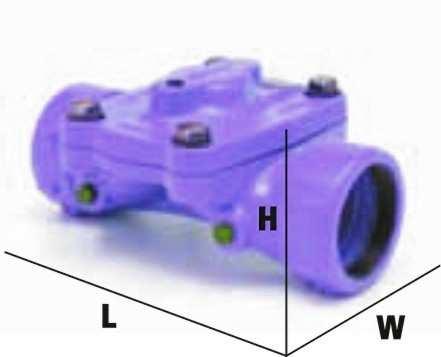
6 P r e s s u r e R e d u c i n g V a l v e Data sheet: P Applications ProVal reducing configurations for general water supply systems with medium pressure rating. The plastic pilot model is best for irrigation and low-pressure applications. The plastic materials and straightforward design provide high corrosion resistance and cost effective prices. The 2-way pilot configuration, together with the unique diaphragm, enables smooth and precise pressure control. Use ProVal valves for domestic, water works, and filtration networks. Description ProValvalves are piloted hydraulic valves activated by line pressure valve has a spring-loaded diaphragm that is sensitive to downstream pressure. The pilot's spring is preset to the desired reduced pressure. The pilot valve maintains a constant downstream pressure by gradually opening and closing the Ooval valves at any flow rate. Available Models 3-way Pressure Reducing Valve for sizes 2-6 with pressure ratings up to 145 PSI (10 bars). 2-way Pressure Reducing Valve with pressure rating up to 232 PSI (16 bars). Function The ProVal Pressure Reducing Valve is activated by line pressure and controlled by the pilot valve. The pilot includes a springloaded diaphragm that is exposed to the downstream pressure. The displacement of the membrane due to downstream fluctuation defines the flow direction inside the pilot. When the downstream pressure is lower than desired, the valve is automatically directed to open. In the reverse case, it is automatically directed to close. When line pressure is inserted into the control chamber of the valve (above its diaphragm) the valve closes. When the control chamber drains, the valve opens as a result of the line pressure from below its diaphragm. In two-way configurations, the control chamber drains downstream, enabling faster reaction time and gradual opening without water discharge. Control Mode 3-way Plastic Pilot Control Mode 2-way Pilot Manual: Use the three-way selector to close or open the valve by turning the handle to C (closed) or O (open). Automatic: Position the three-way selector handle to A (automatic). When the downstream pressure is lower Manual: To open the valve, open isolation valves 1 and 2. To close the ProVal, close the downstream isolation valve. Automatic: When the downstream pressure is lower than that of the pilot spring, the control chamber drains downstream and the than that of the pilot spring, the valves control valve opens. In this case, there is a connection between port 3 chamber drains via ports s 3 and 2 of the pilot to open (inlet upstream), port 1 or 2 (outlet downstream) and the control the valve. When the downstream pressure is too high, chamber. When the downstream pressure rises above the preset the pilot diaphragm moves upward allowing ports 3 and spring load, the pilot's diaphragm is forced upward, closing port 1 4 to connect, thus permitting line pressure to close. or 2. The valve then begins closing and downstream pressure decreases. In three-way configurations, the control chamber drains out to atmosphere, permitting the valve to open entirely.


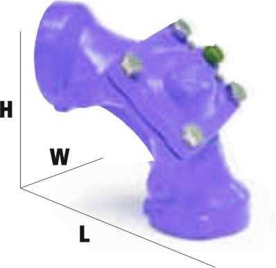
7 Pressure Sustaining Valve Data sheet: P Applications Use the pressure sustaining/relief valve to maintain constant upstream pressure and to avoid undesirable high-pressure situations. This protection is required for most irrigation systems, domestic and industrial utilities, and for general water supply systems. The 3-way plastic pilot model provides high resistance to corrosion at a cost effective price. It is best for irrigation, filtration manifolds, water treatment circulation and low-pressure domestic applications. The 2- way pilot command provides smooth and precise pressure control. Description The pilot valve has a spring-loaded diaphragm that is exposed to upstream pressure. The valve is normally closed. With Pressure Relief Valves, only when the line pressure rises above a preset point does the valve open to reduce the excessive upstream pressure. The excess pressure is released off-line. Pressure Sustaining Valves reduce the excessive downstream pressure without causing surge hazards. When the line pressure drops beneath the desired point, the valve closes. Available Models 3-way plastic piloted pressure sustaining/relief valve for sizes 2-6 with pressure rating up to 145 PSI (10 bars). 2-way Pressure Sustaining/Relief Valve with pressure rating up to 232 PSI (16 bars). Function The Pressure Sustaining/ Relief Valve is activated by the line pressure and controlled by a pilot valve. A sustained pressure is preset by adjusting the pilot retaining spring. The pilot is connected to line pressure (upstream). The displacement of the pilot's spring-loaded diaphragm due to upstream pressure defines the flow direction inside the pilot. When the upstream pressure is higher than the set point, the valve is piloted to open. Otherwise the valve remains closed, maintaining the upstream pressure. The excess line pressure is relieved downstream. In 3-way pilot configurations, the valve control chamber drains out, enabling the valve to open fully. In 2- way pilot configurations, the control chamber drains downstream, enabling faster reaction time and gradual closure without water discharge. Control Mode 3-way Plastic Pilot Control Mode 2-way Pilot Manual: Use the three-way selector to close or open the valve by turning the handle to C (closed) or O (open) positions. Automatic: Position the three-way selector handle to A (automatic). When the upstream pressure is low, the pilot's membrane is in its lowest position. The valve's control chamber is exposed to line pressure through ports of the pilot. The valve closes to sustain the upstream pressure. When the upstream pressure is higher than preset, the Manual: To open the valve, open isolation valves 1 and 2. To close the valve, close the downstream isolation valve. The upstream isolation valve should remain open. Automatic: When the upstream pressure is lower than that of the sustained pressure set point, the valve's control chamber is connected to the line. This connection occurs through ports 1 or 2 (inlet upstream) and port 3. The valve closes until the desired upstream pressure is achieved. When the upstream pressure rises above the set point, the pressure overcomes the pilot's spring and forces the pilot's pilot's diaphragm is forced upward. Port 5 (outlet diaphragm to move upward. The connection between ports downstream) opens and the control chamber of the valve 3-4 opens and port 2 closes. The control chamber drains drains downstream, alleviating the excess pressure. and the valve opens to relieve the excessive pressure downstream. In 3-way configurations, the control chamber drains out to atmosphere, permitting the valve to open entirely.

 configurations, the valve remains closed until the hydraulic relay receives a hydraulic command.")
8 Hydraulic Remote Control Data sheet: P Applications Use valve with a hydraulic remote control in those situations where the command pressure is lower or higher then the working pressure or in situations where there are topographic differences between the command source and the line water pressure at the valve. The hydraulic remote control is also used where the use of wires is not feasible. Description On/Off hydraulic remote control valves are used for the remote control of hydraulic valves. In normally closed (NC) configurations, the valve remains closed until the hydraulic relay receives a hydraulic command. In the normally open (NO) model, the valve is open until the hydraulic relay receives a hydraulic command to close. Available Models Normally open and normally closed configurations are available. Operating pressure is up to 145 PSI (10 bars). A pressure regulating or pressure sustaining pilot may be used in conjunction with the hydraulic relay. Function The valve is activated by line pressure and controlled by the hydraulic relay. The relay includes a spring-loaded diaphragm that determines the pressure required to activate the command. In the normally closed operation (NC), the line pressure is connected to the valves control chamber keeping the valve closed. In the reverse case (NO), the valve remains in the open position. Control Mode Normally Closed Mode: In normally closed applications, when the command is received through port 1, the line pressure port 2 is prevented from entering the control chamber through the connection between port and the water in the control chamber drains through port 3, causing the valve to open. Normally Open Mode: In normally open applications, port 3 connects to the upstream line pressure and water is prevented from entering the bonnet. When the command is received through port 1, 1 port 3 connects to port 4 and the valve closes. Basic Valve Basic valve can be operated manually through the use of a 3-way selector. Selector options are: Closed: Upstream pressure or pressure from an external source is applied to the control chamber. The diaphragm is pressed down to close the valve drip-tight. Open: Discharging the water or air pressure to the atmosphere from the control chamber causes the valve to open. Automatic: The automatic port of the 3-way selector is connected to a solenoid, hydraulic relay or pilot, which controls the valve. The common port of the 3-way selector connects the control chamber to either A (automatic), O (open) or C (closed), depending on the direction the selector is pointed.

9 E l e c t r i c C o n t r o l Data sheet: P Applications On/Off electric valves are used for remote control of hydraulic valves. Normally open or normally closed configurations are available. Description The valve opens or closes by electric command through a selection of either 2-way or 3-way solenoid valves. The solenoid opens or closes the valve when energized by an electric signal. The electric signal originates from a controller, timer, sensor or remote control device. Available Models Three-way normally closed and 3-way normally open electric control valve. Two-way normally closed and 2-way normally open electric control valve. Function 2-way configuration: The valve's control chamber drains downstream, enabling faster C = Common P = Pressure V = Vent and gradual opening without water discharge. 3-way configuration: The valve control chamber drains to atmosphere, allowing the valve to open fully. Control Mode Normally Closed Mode: The line pressure is connected to the valve's control chamber above its diaphragm via port P (pressure) and port C (common). The diaphragm is pressed downward against the valve seat, closing the valve. As an electric signal energizes the normally open (NO) solenoid, its plunger changes position and the control chamber drains out through port V (vent). The diaphragm is forced upward by the line pressure and the valve fully opens. Normally Open Mode: The valve's control chamber is connected to port C (common) of the solenoid. The valve's diaphragm is pressed upward by line pressure keeping the valve in the open position. As the normally closed (NC) solenoid is energized by an electric signal, its plunger changes position and the vent closes. The control chamber of the valve becomes connected to the pressure source via port P (pressure) and port C and the valve closes.


.")

10 C o n t r o l P i l o t s Data sheet: P P-21 2-way Pressure Reducing metal pilot PSI ( bar). P-22 2-way Pressure Sustaining metal pilot PSI ( bar). P-23 2-way Quick Relief metal pilot PSI ( bar). P-24 Altitude metal pilot PSI ( bar). P-31 3-way Pressure Reducing/Sustaining plastic pilot PSI ( bar). P-31D 3-way differential pressure plastic pilot PSI ( bar).

11 P r o c ess under Control? Y e s w e c a n! Quelle der verwendeten Bilder im Prospekt: Urheber: Eray Haciosmanoglu, Orlando Florin Rosu, erikdegraaf, christian42, Dan Race, Paul Stock, Thaut Images P r o C o n V a l G m b H P r o C o n V a l G m b H E n g i n e e r i n g D e p. A m B a u h o f 2 2 O b e r l i n d a u 2 1 D D i e b u r g D F r a n k f u r t / G e r m a n y T e l ( 0 ) F a x ( 0 ) S k y p e : P r o c o n v a l T e l ( 0 ) e m a i l : i n f P r o C o n V a l. c o m F a x ( 0 )
Pilots Specifications
 ilots Specifications - -way ressure Reducing metal pilot. 7-0 SI (0.-6 bar) - -way ressure Sustaining metal pilot. 7-0 SI (0.-6 bar) - -way Quick Relief metal pilot. 7-0 SI (0.-6 bar) - Altitude metal
RAF Diaphragm Control Valves for Waterworks
 RAF Diaphragm Control Valves for Waterworks RAF PURPOSE HYDRAULIC VALVES Technical Information Contents RAF 10 Float Level Control Valve 67 RAF 1031 Electric Float Control Valve 89 RAF 13 Bi level Float
Ø248 Ø Series. R 2.00 R 2 Hydraulic Control Valves R 3 R 6 SEE "SEAT DE T DETAIL NO. 2" CONTROL VALVES
 Ø290 Ø248 Ø240 RAM Ø201 400 Series R 2.00 R 2 Hydraulic Control Valves R 3 G 50 92 30 R 6 SEE "SEAT DE T DETAIL NO. 2" Ø290 Ø248 Ø240 Ø201 30 i n d e x How To Order R 2.00 R 2 2 Company profile 4 Hydraulic
SINGLE VALVE WITH LOW-FLOW BYPASS
 CONTROL VALVES Pressure Reducing Valve Sizing Guide Sizing pilot operated reducing valves is not a complicated process. It starts with determining requirements and following these guidelines in valve size
BERMAD Fire Protection Hydraulic Control Valves
 BERMAD Fire Protection Hydraulic Control Valves Control Solutions with the Power to Protect BERMAD - The Company Since its foundation in 1965, BERMAD has focused its efforts on innovation, quality and
The Future of Hydraulic Control in Water-Systems
 The Future of Hydraulic Control in Water-Systems A. Heimann Manager of R&D and of Technical Support & Applications Engineering departments at Dorot Automatic Control Valves Dorot Control Valves, Kibbutz
300 Series. Automatic Hydraulic Control Valves
 Automatic Hydraulic Control Valves AVFI Pty Ltd 54 Enterprise Drive Bundoora Vic 3083 p: 03 8467 0000 f: 03 8467 0099 e: avfi@avfi.com.au w: www.avfi.com.au 300 Series General 300 SERIES Automatic Hydraulic
MWEA MAINTENANCE SEMINAR SPECIALTY VALVES POWER GLOBES
 MWEA MAINTENANCE SEMINAR SPECIALTY VALVES POWER GLOBES J O H N G. H U N T E R Types of Valves P A U L M A R C H I Accessories Principals of Operation Maintenance Control Valve Types Common Problems Key
SUBMITTAL NOTES PROJECT: Ross Model 50RWR-A Pilot Operated Surge Relief Valve with Hydraulic Anticipation. Size: inch / mm
 SUBMITTAL NOTES PROJECT: Ross Model 50RWR-A Pilot Operated Surge Relief Valve with Hydraulic Anticipation Size: inch / mm Every Ross Valve shall be hydrostatically tested for body integrity and tight seating
BACK PRESSURE / SUSTAINING
 In many liquid piping systems, it is vital that line pressure is maintained within relatively narrow limits. This is the function of the 108 Pressure Relief / Back Pressure Series of the OCV control valves.
BACK PRESSURE / SUSTAINING
 SPECIFICATIONS DIMENSIONS In many liquid piping systems, it is vital that line pressure is maintained within relatively narrow limits. This is the function of the 108 Pressure Relief / Back Pressure Series
Cash Valve TYPE KP PILOT OPERATED BACK PRESSURE VALVE. ISSUED - DECEMBER 2000 CAVMC-0518-US-0208 ISO 9001 Certified
 Cash Valve PILOT OPERATED BACK PRESSURE VALVE ISSUED - DECEMBER 2000 CAVMC-0518-US-0208 ISO 01 Certified KP HIGH CAPACITY PILOT OPERATED BACK PRESSURE VALVE DESCRIPTION The Cash Valve Type KP is a pilot
Waterous Relief Valve
 Operating Instructions 1. Reduce pump discharge pressure with engine throttle. Make sure four way (On/Off) valve is OFF. 2. Open at least one discharge valve. Accelerate engine until pressure gage indicates
my SYSTEM A guide to common applications in water distribution systems
 my SYSTEM A guide to common applications in water distribution systems WWW.SINGERVALVE.COM INDEX This short guide is intended to offer guidance on some of the common problems, applications and questions
BERMAD Waterworks. Level Control Valve with Altitude Pilot. 700 Series. Model X. Features and Benefits. Major Additional Features
 Level Control Valve with Altitude Pilot High level reservoirs & water towers Energy cost critical systems Systems with poor water quality Inherent refreshing Level sustaining at reservoir outlet The Level
DN300 DN2000 C Plunger Valve
 ל DN300 DN2000 C Plunger Valve P.O.B 46 MOSHAV SHTULA WESTERN GALILEE 2286500 Tl. +972-(0)77-6656101, Fax. +972-(0)77-6656196 Website: www.saisanketvalves.com www.saisanket.com email: saisanket@saisanket.com
IWCF Equipment Sample Questions (Surface Stack)
") IWCF Equipment Sample Questions (Surface Stack) 1. During a well control operation 4000 psi was shut in below the middle pipe rams. Ram type BOP data: Model: Cameron U type Rated Working Pressure: 15000
IWCF Equipment Sample Questions (Surface Stack) 1. During a well control operation 4000 psi was shut in below the middle pipe rams. Ram type BOP data: Model: Cameron U type Rated Working Pressure: 15000
VALVES HIDROMATIC VALVE.
 VALVES HIDROMATIC VALVE Hydrodynamic design The Hidromatic valve of Hidroconta is a piston hydraulic valve controlled with the same fluid of the conduction. Its balloon design improves its hydrodynamic
Installation and operation Manual. Bermad Surge Anticipation Valve. Model No 435
 Instruction manual Bermad surge anticipation manual Model No 435 Installation and operation Manual Bermad Surge Anticipation Valve Model No 435 Bermad Water Technologies Rev 0 5/05/2015 7 Inglewood Drive,
Operation & Maintenance Manual Place this manual with valve or person responsible for maintenance of the valve
 Operation & Maintenance Manual Place this manual with valve or person responsible for maintenance of the valve Model CYCLE GARD II, CI & CNA YOUR PRODUCT INFORMATION: Model Number: Date: Serial Number:
Model: 43T. Bermad Pressure Relief Valve
 Model: 43T Bermad Pressure Relief Valve Installation Operation Maintenance Manual () Rev.C1_01.08.17 Page 1 of 10 Safety First BERMAD believes that the safety of personnel working with and around our equipment
I T T Pressure Reducing Valve WARNING INSTALLATION, OPERATION, AND MAINTENANCE MANUAL
 INSTALLATION, OPERATION, AND MAINTENANCE MANUAL I-867-4T 867-4T Pressure Reducing Valve HANG THESE INSTRUCTIONS ON THE INSTALLED VALVE FOR FUTURE REFERENCE WARNING Read and understand all instructions
CAST IRON VALVES FLOAT VALVE
 CAST IRON VALVES FLOAT VALVE NETAFIM CAST IRON VALVES FLOAT VALVE INLINE 25-400MM ANGLE 50-100MM SPECIFICATIONS Manufactured to ISO 9001 Available Valve sizes INLINE Flanged 50mm to 600mm & Threaded 19mm
Spring Loaded Regulators Constant Loaded Regulators Twin Parallel Flow Regulators Field Service Regulators
 Product Line Brochure J0B Effective Date 2/01 Spring Loaded Regulators Constant Loaded Regulators Twin Parallel Flow Regulators Field Service Regulators P R O D U C T L I N E O V E R V I E W Regulator
SINGER MODEL 106/206-RPS-L&H
 DESCRIPTION: Model 106/206-RPS-L&H dissipates surges caused by power failure to pumps. The valve anticipates the surge by opening on low line pressure associated with sudden stopping of pumps. This assures
BAKER CONTROL VALVES Member of the. group AVK SOUTHERN AFRICA THE ART OF FLOW CONTROL
 BAKER CONTROL VALVES Member of the group AVK SOUTHERN AFRICA THE ART OF CONTROL INTRODUCTION THE BAKER CONTROL VALVE HAS PLAYED A SIGNIFICANT ROLE IN THE WATER AND MINING INDUSTRIES SINCE 97. For more
Lesson 6: Flow Control Valves
 : Flow Control Valves Basic Hydraulic Systems Hydraulic Fluids Hydraulic Tank Hydraulic Pumps and Motors Pressure Control Valves Directional Control Valves Flow Control Valves Cylinders : Flow Control
BEFORE SALES AFTER SALES
 TALIS FP RANGE TALIS FP RANGE TALIS is a leading global provider of premium valves, hydrants and control solutions for water flow control and Fire Protection Systems With a varied range of products, Talis
TECHNICAL DATA. the Viking Pilot Pressure Regulating Valve 1 Model A-1 Speed Control Assembly: OBSOLETE. the Viking Speed Control Assembly 1
 November 30, 1994 534 a 1. PRODUCT NAME VIKING 2" (50mm), 3" (75mm), 4" (100mm), 6" (150mm) 2. MANUFACTURER THE VIKING CORPORATION 210 N. Industrial Park Road Hastings, Michigan 49058 U.S.A. Telephone:
Discharge Relief Valve Operation & Maint.
 Relief Valve Operation & Maint. CZ Series Centrifugal Fire Relief svalve Operation and Maintenance Instructions 1410 Operation and Maintenance Form No. F-1031 Section 2302.6 2111 Issue Date 04/90 11/95
CASH VALVE TYPE KP BACK PRESSURE VALVES
 A high capacity pilot operated back pressure valve that offers accurate control and dependable protection against overpressure conditions FEATURES Automatically maintains maximum pressure in a vessel or
TECHNICAL DATA. Q = C v P S
 Preaction 346a 1. Description The 6 Model G-6000P Electric Release Preaction System Riser Assembly can be used as a Single Interlock Preaction System with Electric Release, or as a Double Interlock Preaction
TECHNICAL DATA. Q = C v P S
 Page 1 of 13 1. DESCRIPTION The Viking 6 Model G-6000 Dry Valve Riser Assembly consists of a small profile, light weight, pilot operated valve that is used to separate the water supply from the dry sprinkler
Principle of Operation. Features. Applications. CL34 Operating Schematic
 ..GAS.REGS..GAS.REGS Principle of Operation (See Operating Schematic below) pressure connected by tubing to the pilot regulator, is utilized as supply pressure for pilot. pressure of the Regulator is applied
Bermad Pressure Reducing. Model: 42T
 Bermad Pressure Reducing Pilot Operated Pressure Control Valve Model: 42T Installation Operation Maintenance Manual (IOM) REV. 27.7.17 Page 1 of 12 Safety First BERMAD believes that the safety of personnel
Modulating Valves for Atmospheric, Infrared, and Direct Fired Burners
 BULLETIN MT2035-07/05 Modulating Valves for Atmospheric, Infrared, and Direct Fired Burners M/MR Series M411, M511, M611 M420, M520, M620, MR410, MR510, MR610 MR212D, MR212E, MR212G and MR212J (Flanged),
TECHNICAL DATA 3 MODEL G-3000 DRY VALVE RISER ASSEMBLY
 Page 1 of 13 1. DESCRIPTION The Viking 3 Model G-3000 Dry Valve Riser Assembly is equipped with a small profile, light weight, pilot operated valve that is used to separate the water supply from the dry
TECHNICAL DATA. Page 1 of 12
 Page 1 of 12 1. DESCRIPTION The Viking Regulating Valve is a direct-acting, single-seated, spring-loaded diaphragm valve. When installed as a pilot regulating valve on a Viking Model H or J Flow Control
TECHNICAL DATA. Q= Cv S
 Page 1 of 13 1. DESCRIPTION The Viking 4 inch Model G-4000 Dry Valve Riser Assembly consists of a small profile, light weight, pilot operated valve that is used to separate the water supply from the dry
TECHNICAL DATA. Q = C v P S
 January 6, 2012 Preaction 348a 1. Description Viking supervised Surefire Preaction Systems utilize the Viking G-6000P Valve. The small profile, lightweight, pilot operated Viking G-6000P Valve comes complete
Model: 720-UL INSTALLATION OPERATION MAINTENANCE. Bermad Pressure Reducing Valve IOM. Model: FP -720-UL Sizes: 2"-12" BERMAD. Application Engineering
 Bermad Pressure Reducing Valve Model: 720-UL INSTALLATION OPERATION MAINTENANCE Application Engineering BERMAD 1. Safety First BERMAD believes that the safety of personnel working with and around our equipment
INSTALLATION OPERATION MAINTENANCE
 Bermad Electrically Controlled On-Off Deluge Valve Model: 400E-3D INSTALLATION OPERATION MAINTENANCE Application Engineering BERMAD 1. Safety First BERMAD believes that the safety of personnel working
WW-730. Pressure Sustaining/Relief Control Valve
 WW-730 Pressure Sustaining/Relief Control Valve Installation Operation & Maintenance Page 1 of 6 1. DESCRIPTION The Model 730 Pressure Relief / Sustaining Valve is an automatic control valve designed to
STAND ALONE SPREADER INSTALLATION INSTRUCTIONS AND OPERATOR S MANUAL
 STAND ALONE SPREADER INSTALLATION INSTRUCTIONS AND OPERATOR S MANUAL FEATURES VALVE FUNCTIONS ADJUSTMENTS SCHEMATICS Muncie Power Products, Inc. TABLE OF CONTENTS DESCRIPTION PAGE Features... 3 Hydraulic
TECHNICAL DATA Q= C. Table 1 - Specifications
 September 25, 2013 Pressure Regulation 537a 1. Description The Model B-3 Pilot Operated Pressure Control Valve is a factory assembled unit. The unit consists of a Model J-2 Halar coated Flow Control Valve,
TECHNICAL DATA Q = C. v P S. 2 Model G-2000 Dry valve. Page 1 of 13
 Page 1 of 13 1. Description The Viking 2 Model G-2000 Dry Valve Riser Assembly consists of a small profile, light weight, pilot operated valve that is used to separate the water supply from the dry sprinkler
TECHNICAL DATA. Pressure Regulation 531a. April 24, 2009
 April 24, 29 Pressure Regulation 531a 1. DESCRIPTION The Viking Regulating Valve is a direct-acting, single-seated, spring-loaded diaphragm valve. When installed as a pilot regulating valve on a Viking
Time-Delay Electropneumatic Applications
 Exercise 3-4 EXERCISE OBJECTIVE & & & To introduce time delays; To describe the operation of a time-delay valve; To describe the operation of a time-delay relay. DISCUSSION Time-Delays Time delays are
TECHNICAL DATA. Table 1 - Specifications
 Page 1 of 6 1. DESCRIPTION Model A-3 Pilot Operated Pressure Control Valves are factory assembled units. Each unit consists of a Model H-2 Halar coated Flow Control Valve, a Speed Control Valve, a Model
PILOT OPERATED PRESSURE VACUUM RELIEF VALVE MODEL 1660
 PILOT OPERATED PRESSURE VACUUM RELIEF VALVE MODEL 1660 Patent Protected Premium Seat Tightness to Set Pressure Snap or Modulating Valve Action Provides Ability to Meet Clean Air Act Requirements 600 TYPICAL
MESP-202H INSTALLATION INSTRUCTIONS AND OWNER S MANUAL. HF and HF FEATURES VALVE FUNCTIONS ADJUSTMENTS SCHEMATICS
 MESP-202H INSTALLATION INSTRUCTIONS AND OWNER S MANUAL FEATURES VALVE FUNCTIONS ADJUSTMENTS SCHEMATICS HF42407-07 and HF51912-09 Muncie Power Products, Inc. TABLE OF CONTENTS DESCRIPTION PAGE Features...
WHEATLEY WHEATLEY SERIES 500 SWING CHECK VALVE. Installation, Operation and Maintenance Manual
 WHEATLEY SERIES 500 SWING CHECK VALVE STANDARD INTEGRAL SEAT & OPTIONAL REMOVABLE SEAT 2" FP - 6" FP 150# - 1500# 8" FP - 12" FP 150# - 900# API 6D and B16.34 2" FP - 4" FP 5000# DRILLING PRODUCTION VALVE
Reduce pressure zone device suitable for high and medium hazard rated applications BSP screwed connections
 Reduce pressure zone device suitable for high and medium hazard rated applications BSP screwed connections Features General application The RP03 provides protection from both backsiphonage and backpressure
Type S301 & S302 Gas Regulators INTRODUCTION INSTALLATION. Scope of Manual. Description. Specifications. Type S301 and S302. Instruction Manual
 Fisher Controls Instruction Manual Type S301 & S302 Gas Regulators October 1981 Form 5180 WARNING Fisher regulators must be installed, operated, and maintained in accordance with federal, state, and local
TECHNICAL DATA. Q = C v P S
 January 6, 2012 Preaction 333a 1. Description Viking supervised Surefire Preaction Systems Utilize the Viking G-3000P Valve. The small profile, lightweight, pilot-operated Viking G-3000P Valve comes complete
Pressure and/or Temperature Pilot Operated Steam Regulators Series 2000
 Hoffman Specialty Regulators Regulators Pressure and/or Temperature Operated Regulators Series 2000 The Hoffman Specialty Series 2000 consists of main valves, pilot valves, wells and hardware kits. They
Date of Issue: July 2016 Affected Publication: API Specification 16C, Choke and Kill Equipment, Second Edition, March 2015 ADDENDUM 1
 Date of Issue: July 2016 Affected Publication: API Specification 16C, Choke and Kill Equipment, Second Edition, March 2015 ADDENDUM 1 Page 16, Section 4.6, delete the entire section and renumber all subsequent
American Society of Sanitary Engineering PRODUCT (SEAL) LISTING PROGRAM
 LISTING PROGRAM") American Society of Sanitary Engineering PRODUCT (SEAL) LISTING PROGRAM ASSE STANDARD #1019 - REVISED: 2011 Wall Hydrant with Backflow Protection and Freeze Resistance MANUFACTURER: CONTACT PERSON: E-MAIL:
American Society of Sanitary Engineering PRODUCT (SEAL) LISTING PROGRAM ASSE STANDARD #1019 - REVISED: 2011 Wall Hydrant with Backflow Protection and Freeze Resistance MANUFACTURER: CONTACT PERSON: E-MAIL:
FILTER BYPASS CONTROL
 Differential Control Valve Series 110 The Series 110 Differential Control Valve is designed to accurately control the pressure difference between any two points. In some systems this means the valve remains
Hydraulics. Hydraulic Pressure Control
 Hydraulics Hydraulic Pressure Control Direct Acting Pressure Relief Valve Normally Closed: Pilot Operated Relief Valve (Compound/ two stage) Small pilot relief valve + Main relief valve Pilot Operated
Liquid Level Controllers
 Liquid Level Controllers ALL PUMPS LLC-2Y For both pump up and down control. Variable On/Off set points. NDP-15/20/25/32, DP-10/15 & *NDP-40/50/80 LLC-1 Pump up and down versions available. 6 to 12 differential
Digester Processes. 1. Raw Sludge Pumping System
 Digester Processes 1. Raw Sludge Pumping System Removes accumulated sludge from the primary clarifiers, pumped through 1 of 2 pipes either 150 or 200mm in diameter (Fig. 1.1). Fig 1.1 Pipes feeding Digesters
Rate of Flow Valve Series 120
 SPECIFICATIONS Rate of Flow Valve Series DIMENSIONS The OCV Series 120 Rate of Flow control valve is designed to control or limit flow to a predetermined rate, regardless offl uctuations in downstream
TECHNICAL DATA CAUTION
 Page 1 of 12 1. DESCRIPTION The Viking Model C-2 Pilot Pressure Regulating Valve is a direct-acting, single-seated, spring-loaded diaphragm valve. When installed as a pilot regulating valve on a Viking
Pressure Reducing Control Valve w/ Hydraulic Check Feature
 PERTIN INSTRUTINS peration The BEE Model PR- Pressure Reducing ontrol alve with Hydraulic heck eature is a pilot controlled diaphragm valve designed to reduce a fluctuating higher upstream pressure to
Model 1800 PFM Series Regulator. Technical Bulletin
 Model 0 PFM Series Regulator Technical Bulletin Model 0 PFM Series Regulator 0 Elster American Meter The 0 PFM Series regulators are designed to control natural gas, air, nitrogen, carbon dioxide, propane
Model DDX-LP Dry Pipe Valve System 8 (200mm) Features. Differential latching clapper-type, lighweight, dependable construction.
 Features. Differential latching clapper-type, lighweight, dependable construction.") Bulletin 335 Model DDX-LP Dry Pipe Valve System 8 (200mm) Bulletin 335 Features 1. 2. 3. 4. 5. 6. 7. 8. 9. 10. 11. 12. Differential latching clapper-type, lighweight, dependable construction. Low Air Pressurized
Bulletin 335 Model DDX-LP Dry Pipe Valve System 8 (200mm) Bulletin 335 Features 1. 2. 3. 4. 5. 6. 7. 8. 9. 10. 11. 12. Differential latching clapper-type, lighweight, dependable construction. Low Air Pressurized
TECHNICAL DATA. Q = C v P S
 January 6, 2012 Preaction 347a 1. Description Viking supervised Double-Interlocked Electric/Pneumatic Release Preaction Systems utilize the Viking G-6000P Valve. The small profile, lightweight, pilot operated
VACUUM REGULATORS CONTENTS
 CAD drawing data catalog is available. ACCESSORIES GENERAL CATALOG AIR TREATMENT, AUXILIARY, VACUUM, AND FLUORORESIN PRODUCTS CONTENTS Small Regulators Features 759 Specifications, Order Codes, Flow Rate
SPECIFICATIONS. Approximate Weight: 10 oz. Surface Finish: Ra micro inch or less MATERIALS OF CONSTRUCTION
 DIFFUSION-RESISTANT, DIAPHRAGM SEAL, EXCESS FLOW SHUT-OFF VALVES (FS SERIES) FS Series Excess Flow Shut-Off Valves are designed to automatically shut-off the delivery of gas in a line if the flow exceeds
Installation Operation Maintenance. Bermad Level Control Valve with Modulating Horizontal Float Pilot valve One Way Flow IOM.
 Bermad Level Control Valve with Modulating Horizontal Float Pilot valve One Way Flow Model: FP 450-80 Installation Operation Maintenance PAGE 1 OF 5 1. Safety First BERMAD believes that the safety of personnel
1800CPB2 Pilot-Loaded Service Regulators
 1800CPB2 Pilot-Loaded Service Regulators Technical Bulletin www.elster-americanmeter.com Table of Contents 1800CPB2 Regulator Information................ 2-3 1800CPB2 Capacity Performance................
1800CPB2 Service Regulators Maximum Inlet Pressure 125 PSIG
 A C E D SB-8520.2 1800CPB2 Service Regulators Maximum Inlet 125 PSIG AMC Quality System QMI is Accredited by: C R E D I T ISO 9001 Certified Certificate #006697 R E ANSI RAB G I S T R A R Dutch Council
Exercise 5-2. Bubblers EXERCISE OBJECTIVE DISCUSSION OUTLINE. Bubblers DISCUSSION. Learn to measure the level in a vessel using a bubbler.
 Exercise 5-2 Bubblers EXERCISE OBJECTIVE Learn to measure the level in a vessel using a bubbler. DISCUSSION OUTLINE The Discussion of this exercise covers the following points: Bubblers How to measure
TECHNICAL DATA. TRIMPAC Model B-5 & B-5B
 September 16, 2013 Trimpac 250a 1. DESCRIPTION DEsCRIPTIoN is a factory assembled trim package for a ed an electric/pneumatic release module in a metal enclosure. The standard trim normally required on
Data Sheet Issue A
 Features 1. Differential latching clappertype, lighweight, dependable construction. 2. Low Air Pressurized System, 8 psi -to- 26 psi (0,6 bar to- 1,8 bar) 3. Reset externally. Cover removal is not required.
Pilot HON 630a, HON 640
 product information serving the gas industry worldwide pplication, characteristics, technical data pplication pilot for gas pressure regulators HON 0, HON 0, HON 0, HON 0 suitable for natural gas and all
VALVCHEQ BACKFLOW PREVENTERS FIGURE RP03
 Reduce pressure zone device suitable for high and medium hazard rated applications BSP screwed connections FEATURES GENERAL APPLICATION The RP03 provides protection from both backsiphonage and backpressure
TECHNICAL DATA OBSOLETE
 April 9, 2009 Preaction 326a 1. DESCRIPTION Viking supervised Double-Interlocked Electric/Pneumatic Release Preaction Systems utilizing the Viking G-4000P Deluge Valve. The small profi le, lightweight,
FAULT CODE TROUBLESHOOTING INDEX
 FAULT CODE TROUBLESHOOTING INDEX 1. Display indicates Change Filters 2. Display indicates Drip Tray Full Continuous Alarm will Sound 3. Display indicates Cold Fault 4. Display indicates Hot Fault 5. Display
FUNDAMENTALS OF PRESSURE REGULATORS ROBERT BENNETT MANAGER OF TRAINING ELSTER AMERICAN METER
 FUNDAMENTALS OF PRESSURE REGULATORS ROBERT BENNETT MANAGER OF TRAINING ELSTER AMERICAN METER SUPPLY = DEMAND FUNCTION OF A REGULATOR A regulator may be defined as a "mechanism for controlling or governing
SB AXIAL FLOW VALVES
 SB9509.3 AXIAL FLOW VALVES The improved technology for pressure regulation The American Axial Flow Valve provides pressure and flow control in high capacity pipelines. It can be used for pressure regulation,
553 Series.
 38467.03 www.caleffi.com Pre-adjustable filling units Copyright 01 Caleffi 3 Series Function The automatic filling valve is a device consisting of a pressure reducing valve with compensating seat, visual
Pressure Regulators. Operating Instructions. Instrumentation
 Pressure Regulators Operating Instructions FAILURE OR IMPROPER SELECTION OR IMPROPER USE OF THIS PRODUCT CAN CAUSE DEATH, PERSONAL INJURY AND PROPERTY DAMAGE. This document and other information from the
PumpAgents.com - Click here for Pricing/Ordering Nominal psi (bar) Cut-In Cut-Out
 Cut-In Cut-Out") PumpAgents.com - Click here for Pricing/Ordering Model 31670-Series Dual Max 7.5 GPM (28 LPM) AUTOMATIC TWO STAGE WATER SYSTEM WITH ACCUMULATOR TANK AND PUMPGARD STRAINER IDEAL FOR PLEASURE AND COMMERCIAL
PumpAgents.com - Click here for Pricing/Ordering Model 31670-Series Dual Max 7.5 GPM (28 LPM) AUTOMATIC TWO STAGE WATER SYSTEM WITH ACCUMULATOR TANK AND PUMPGARD STRAINER IDEAL FOR PLEASURE AND COMMERCIAL
NO SMOKING WHEN OXYGEN IS IN USE.
 GENERAL NO SMOKING WHEN OXYGEN IS IN USE. The oxygen system provides oxygen as required for up to 19 passengers and 2 cockpit crew members. Therapeutic oxygen outlets are also available in the cabin. OXYGEN
Welker Sampler. Model GSS-1. Installation, Operation, and Maintenance Manual
 Installation, Operation, and Maintenance Manual Welker Sampler Model GSS-1 The information in this manual has been carefully checked for accuracy and is intended to be used as a guide to operations. Correct
1800CPB2 Service Regulators
 SB 8520.5 1800CPB2 Service Regulators Maximum Inlet Pressure 125 PSIG Table of Contents 1800CPB2 Regulator Information................ 2-3 1800CPB2 Capacity Performance................ 4-6 1-1/4" Models,
1200 Series Pressure Regulators
 SEE MORE AT SORInc.com Request Quote 1200 Series Pressure SOR pressure regulators are durable, high performing instruments that are designed to provide reliable control of pressure in various stages of
Models 461-S, 461-8S and S Regulators. R-1330 Rev. 7
 Models 461-S, 461-8S and 461-12S Regulators R-1330 Rev. 7 461-S, 461-8S and 461-12S Regulators The Sensus Models 461-S, 461-8S and 461-12S are balanced valve, spring type regulators designed for distribution
Contents. Catalog HY /US Load and Motor Control Valves SERIES CAVITY DESCRIPTION FLOW PRESSURE PAGE NO. LPM/GPM BAR/PSI
 Load and Motor Control Contents SERIES CAVITY DESCRIPTION FLOW PRESSURE PAGE NO. LPM/GPM BAR/PSI STANDARD PILOT ASSISTED CB101... C10-3... Load Control Cartridge Valve...45/12... 380/5500... 5-6 MHC-010-S***
ANTI SHOCK RELIEF VALVE
 ANTI SHOCK RELIEF VALVE Wheeler Road Coventry CV3 4LA England Brüsseler Allee 2 D-41812 Erkelenz Tel. +44(0)2476-217-400 Fax +44(0)2476-217-488 Tel. +49(0)24 31-80 91-0 Fax +49(0)24 31-80 91-19 www.sunhydraulics.com
TECHNICAL DATA. Dry 132a. October 1, 2008
 October 1, 2008 Dry 132a 1. Description Viking High Pressure (HP) Dry Systems utilize a Viking Model E or Model F Deluge Valve to control the water supply to system piping equipped with closed sprinklers.
Float Operated Level Controllers
 CONTENTS Float Operated Level Controllers IM0015 Nov. 2014 PAGE Introduction 1 Scope 1 Description 1 Specification 1 Control Installation 2 INTRODUCTION Side Mount Back Mount Prior to installing, the instructions
Testing Procedures & Trouble Shooting Guide Reduced Pressure Zone Assembly (1/2, 3/4", 1, 1 1/4, 1 1/2" & 2 )
") Testing Procedures & Trouble Shooting Guide Reduced Pressure Zone Assembly (1/2, 3/4", 1, 1 1/4, 1 1/2" & 2 ) First Check Valve Test 1) Bleed all test cocks. First open test cock 4, make sure it is slightly
Testing Procedures & Trouble Shooting Guide Reduced Pressure Zone Assembly (1/2, 3/4", 1, 1 1/4, 1 1/2" & 2 ) First Check Valve Test 1) Bleed all test cocks. First open test cock 4, make sure it is slightly
T e l N o : F a x N o : E m a i l : a i s h c m c - m e. c o m w w w. c m c - m e.
 MU047: Practical Valve Technology: Selection, Installation, Upgrading, Inspection & Troubleshooting MU047 Rev.002 CMCT COURSE OUTLINE Page 1 of 7 Training Description: This five-day intensive course covers
Reduce pressure zone device suitable for high and medium hazard rated applications Flanged end connections
 VALVCHEQ Backflow Preventers Reduce pressure zone device suitable for high and medium hazard rated applications Flanged end connections Features General application The RP03 provides protection from both
M/MR Modulating Valves TABLE OF CONTENTS DESCRIPTION SPECIFICATIONS. For Atmospheric, Infrared, and Direct Fired Burners
 M/MR Modulating Valves design certified For Atmospheric, Infrared, and Direct Fired urners TALE OF CONTENTS Description/Specifications... 1 Introduction... 2 Direct Fired Applications (Negative Pressure)...
Model 7989T Steel Pipe Squeezer Sch. 40 & Sch. 80. Operations Manual
 10-12 Steel Pipe Squeezer Sch. 40 & Sch. 80 Operations Manual 1.0 Introduction This manual is issued as a basic operation manual covering the Regent Model 7989T, Pipe Squeezer and Pump as manufactured
Pressure Regulating Valve Characteristics
 Pressure Regulating Valve Characteristics Charles M. Burt, Ph.D., P.E. Chairman, Irrigation Training & Research Center (ITRC), California Polytechnic State University (Cal Poly), San Luis Obispo, CA 93407-0730,