CHAPTER 3 : AIR COMPRESSOR
|
|
|
- Imogene Fitzgerald
- 5 years ago
- Views:
Transcription
1 CHAPTER 3 : AIR COMPRESSOR Robotic & Automation Department FACULTY OF MANUFACTURING ENGINEERING, UTeM
2 Learning Objectives Identify types of compressors available Calculate air capacity rating of compressor Design the sizing of air receivers Calculate power required to drive compressors

3 3.1 Introduction A compressor is a machine that compresses air or another type of gas from a low inlet pressure to a higher desired pressure level. This is accomplished by reducing the volume of the gas.

4 3.2 Type of Compressor Compressor can be divided into two main groups as illustrated in Figure 3.1. Figure 3.1
5 Positive Displacement Compressor A Displacement Machine or Positive Displacement Compressor consists of a movable member inside housing. The compressor has a piston for a movable member. The piston is connected to a crankshaft, which is in turn connected to a prime mover (electric motor, internal combustion engine). At inlet and outlet ports, valves allow air to enter and exit the chamber. It can be divided into 2 categories such as 1) Reciprocating Compressors and, 2) Rotary Compressors.
6 Reciprocating Compressors. There are two types of reciprocating compressor such as Single Stage Reciprocating Compressor and Multi-Stage Reciprocating Compressor a) Single stage reciprocating compressor, air is drawn in through the input valve during the intake stroke and compressed during the compression stroke and after reaching the correct pressure, is expelled through the exhaust valve b) Multi-stage reciprocating compressor, Smaller pressure difference is chosen and the air is cooled between stages that removes a significant portion of the heat of compression. This increases air density and the volumetric efficiency of the compressor.
7 Reciprocating Compressors. Figure 3.2 Single Stage Reciprocating Compressor Figure 3.3 Multi-Stage Reciprocating Compressors

8 Figure 3.4 : Two stage Compressor

9 Table 3.1 : Effect of number of stages on pressure capacity Number of stages Pressure capacity (PSI)

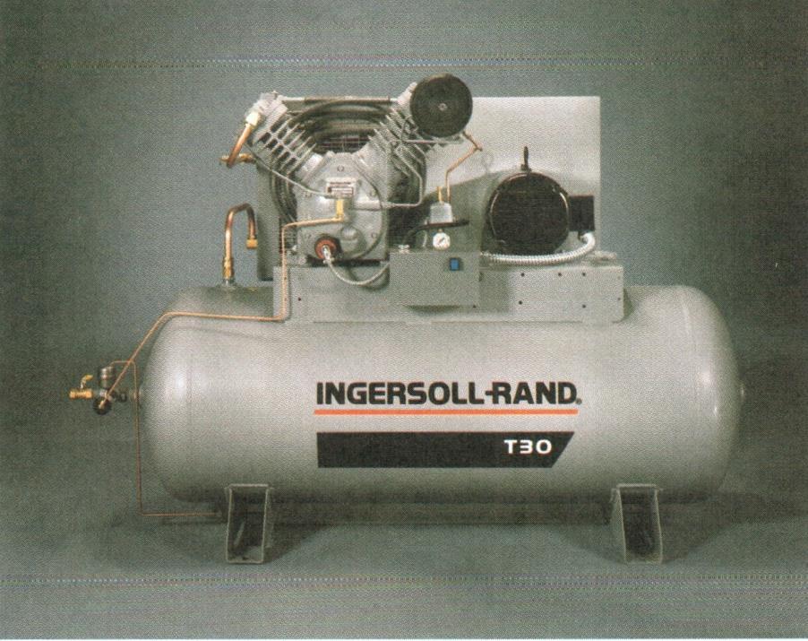
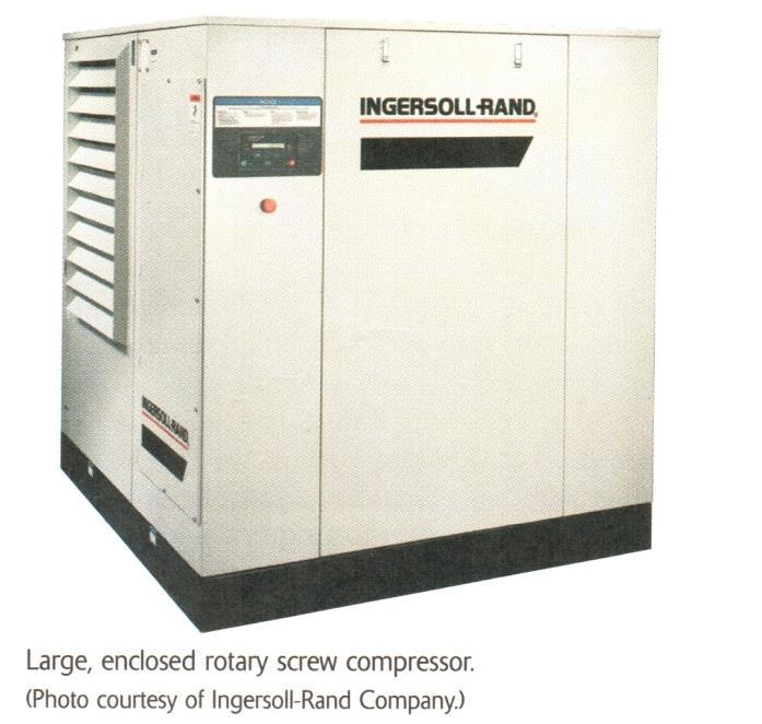
10 Screw Compressor Screw-type Compressor are rotary compressors with two shafts. It stronger and better manufacturing process. They work according to the displacement principle and deliver a continuous supply with no pulsations of pressure fluctuations. Compression is accomplished by rolling the trapped air into a progressively smaller volume as the screw rotate. Screw-type compressors can be built as non-lubricated devices for the supply of oil free compressed air. Figure 3.5 Screw-type Compressor
11

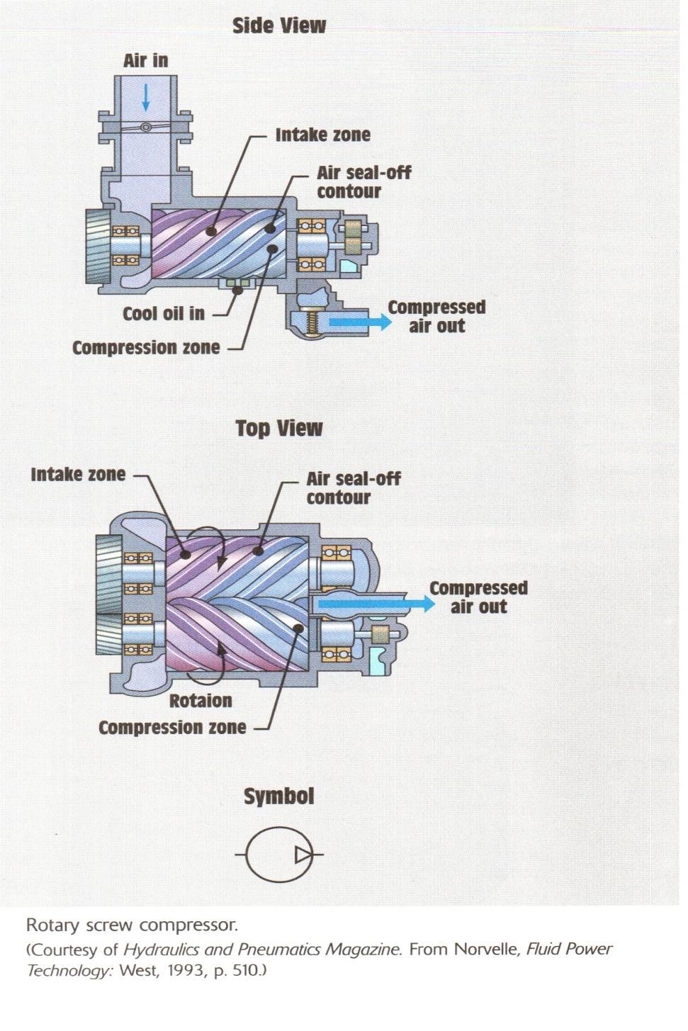
12 Figure 3.6 Rotary Screw Compressor


13 Vane Compressor As the rotor rotates, centrifugal force holds the vanes in contact with the stator wall and the space between the adjacent blades decreases from air inlet to outlet, so compressing the air. Figure 3.7 Sliding Vane Compressors
.")
14 3.3 Air capacity rating of Compressor Air compressor are generally rated in terms of cfm of free air, defined as air at actual atmospheric conditions. SCFM is standard cubic feet per minutes ( 14.7 psia/ 101 KPa abs and 68 o F/ 20 o C). Q 1 Q 2 P 2 P 1 T T 1 2 where 1 represents compressor inlet atmospheric conditions, 2 represents compressor discharge conditions.
15 Example 1 Air is used at a rate of 30 cfm from a receiver at 90 o F and 125 psi. If the atmospheric pressure is 14.7 psia and the atmospheric temperature is 70 o F, how many cfm of free air must the compressor provide? Pounds per square inch absolute (psia) is used to make it clear that the pressure is relative to a vacuum rather than the ambient atmospheric pressure. Since atmospheric pressure at sea level is around 14.7 psi, this will be added to any pressure reading made in air at sea level. The converse is pounds per square inch gauge or pounds per square inch gage (psig), indicating that the pressure is relative to atmospheric pressure. For example a bicycle tire pumped up to 65 psi above atmospheric pressure, will have a pressure of = 79.7 psia or 65 psig. [1][2] Q 2 =30cfm, T=90 o F, P= 125psi T=70 o F, P=14.7psia Solution; Q 1 Q 2 P P 2 1 T T Q 1 30 x cfm of CFM (Cubic Feet per Minute) The absolute zero version of the Fahrenheit scale is the Rankine scale. Add 460 degrees to Fahrenheit temperatures to obtain the Rankine temperature. 1 2 free air The compressor must receive atmospheric pressure (14.7psia, 70 o F) at a rate of 275 cfm in order to deliver air ( 125psi, 90 o F) at 30 cfm
16 Exercise Air is used at a rate of 45 cfm from a receiver at 105 o F and 125 psi. If the atmospheric pressure is 14.7 psia and the atmospheric temperature is 60 o F, how many cfm of free air must the compressor provide? T T P P Q Q Solution;

17 3.4 Sizing of Air Receivers A receiver is an air reservoir. Its function to supply air at essentially constant pressure. It also serves to dampen pressure pulse either coming from the compressor or the pneumatic system during valve shifting and component operation. There are several paramaters need to take into account; 1. system pressure, 2. flow rate requirements, 3. compressor output capability, 4. the type of duty of operation.
18 The below equations can be used to determine the proper size of the receiver V r 14.7t( Q P max r Q P min c ) English units V r 101 t( Q P max r Q P min c ) Metric Units t = time that receiver can supply required amount of air (minute) Qr = consumption rate of pneumatic system ( scfm, standard m 3 /min. Qc= output flow rate of compressor (scfm, standard m 3 /min) Pmax= max pressure level in receiver (psi, KPa) Pmin = min pressure level in receiver (psi, Kpa) Vr= receiver size (ft 3, m 3 )
19 Example 2 Calculate the required size of a receiver that must supply air to a pneumatic system consuming 20 scfm for 6 min between 100 and 80 psi before the compressor resumes operation. Solution; Qc= 0, because of compressor in OFF condition Qr = 20scfm P max = 100psi Supply to pneumatic system Pmin = 80 psi V r 14.7t( Q P max r P Q min c ) V r 14.7x6(20 0) = 88.2 ft 3 It is common practice to increase the calculated size of the receiver by 25% for unexpected overloads and by another 25% for possible future expansion needs
20 Exercise Calculate the required size of a receiver that must supply air to a pneumatic system consuming 30 scfm for 5 min between 100 and 75 psi before the compressor resumes operation. Solution; V r 14.7t( Qr Q P P max min c )
21 3.4 Power Required to Drive Compressors The objective of this design consideration is to meet system pressure and flow rate requirements. The below equations can be used to determine the theoritical power required to drive an air compressor. Theoretical horsepower ( HP) P inq Pout Pin Theoretical power ( KW ) P inq Pout Pin Where, Pin = inlet atmospheric pressure (psia, KPa abs) Pout = outlet pressure (psia, Kpa abs) Q = flow rate (scfm, standard m 3 /min)
22 Example 3 Determine the actual power require to drive a compressor that delivers 100 scfm of air at 100 psig. The overall efficiency of the compressor is 75%. Solution: Theoretical horsepower ( HP) P inq Pout Pin Qout= 100 scfm, Pout = 100psig x HP theory hp HP HP 18.0 theory actual overall 0.75 hp
23 Example 3 Determine the actual power require to drive a compressor that delivers 120 scfm of air at 90 psig. The overall efficiency of the compressor is 80%. Solution: Theoretical horsepower ( HP) P inq Pout Pin
24 Summary Upon completing this topic, you should know; The types of compressors How to design components of a compressor

25 INFORMATION Most pressure gauges on equipment read relative pressure. When an air compressor is off and empty the pressure gauge on it reads zero - but if it's at sea level the air pressure in it is actually about 14.5 psi. So, the zero is relative and when you pump the compressor up to 100 psi on the gauge the actual pressure in the tank is about
Fundamentals of Compressed Air Systems. Pre-Workshop Assignment
 Page 1 In order to ensure that the Compressed Air Challenge Fundamentals of Compressed Air Systems Training is most useful to you, it will be important for you to bring information about your plant s compressed
GLOSSARY OF TERMS. Adiabatic Compression Compression process when all heat of compression is retained in the gas being compressed.
 GLOSSARY OF TERMS Absolute pressure Total pressure measured from absolute zero i.e. a perfect vacuum. As a practical matter, gauge pressure plus atmospheric pressure. Absolute temperature Temperature measured
Advanced Management of Compressed Air Systems Pre-Workshop Assignment
 Advanced Management of Compressed Air Systems Page 1 In order to ensure that the Compressed Air Challenge Level II Training is most useful to you, it will be important for you to bring information about
The most common terms rating air flow capacity are ICFM, FAD, ANR, SCFM or nl/min
 Rating of Air Compressors and Air Equipment The most common terms rating air flow capacity are ICFM, FAD, ANR, SCFM or nl/min There is no universal standard for rating air compressors, air equipment and
Exercise 4-2. Centrifugal Pumps EXERCISE OBJECTIVE DISCUSSION OUTLINE DISCUSSION. Pumps
 Exercise 4-2 Centrifugal Pumps EXERCISE OBJECTIVE Familiarize yourself with the basics of liquid pumps, specifically with the basics of centrifugal pumps. DISCUSSION OUTLINE The Discussion of this exercise
The Discussion of this exercise covers the following points: Pumps Basic operation of a liquid pump Types of liquid pumps The centrifugal pump.
 Exercise 2-3 Centrifugal Pumps EXERCISE OBJECTIVE In this exercise, you will become familiar with the operation of a centrifugal pump and read its performance chart. You will also observe the effect that
(AS AT 31 st MARCH, 2002)
") ACACA PROTOCOL 2000 (AS AT 31 st MARCH, 2002) ACACA PROTOCOL 2000 INCLUDES (A) CODE OF PRACTICE FOR MANUFACTURERS AND/OR SUPPLIERS OF COMMERCIAL AIR COMPRESSORS AND METHOD FOR DETERMINING (B) RECIPROCATING
ACACA PROTOCOL 2000 (AS AT 31 st MARCH, 2002) ACACA PROTOCOL 2000 INCLUDES (A) CODE OF PRACTICE FOR MANUFACTURERS AND/OR SUPPLIERS OF COMMERCIAL AIR COMPRESSORS AND METHOD FOR DETERMINING (B) RECIPROCATING
Understanding Lobe Blowers Roots Blowers. Article written by Technical Team of EVEREST GROUP
 Understanding Lobe Blowers Roots Blowers Article written by Technical Team of EVEREST GROUP ompressors and Fans are essentially pumps for gases. Although they differ in construction from liquid handling
then the work done is, if the force and the displacement are in opposite directions, then the work done is.
 1. What is the formula for work? W= x 2. What are the 8 forms of energy? 3. Write the formula for the following: Kinetic Energy Potential Energy 4. If the force and the displacement are in the same direction,
Applied Fluid Mechanics
 Applied Fluid Mechanics 1. The Nature of Fluid and the Study of Fluid Mechanics 2. Viscosity of Fluid 3. Pressure Measurement 4. Forces Due to Static Fluid 5. Buoyancy and Stability 6. Flow of Fluid and
CHAPTER 3 AUTOMOTIVE AIR COMPRESSOR
 30 CHAPTER 3 AUTOMOTIVE AIR COMPRESSOR 3.1 INTRODUCTION A machine providing air at a high pressure is called as an air compressor. Air compressors have been used in industry for well over 100 years because
Quick Reference Technical Data
 Bulletin 127C 2 Quick Reference Technical Data For over 100 years, The Spencer Turbine Company has specialized in innovative solutions to air and gas handling problems. Spencer's product line includes
Quiz #1 Thermodynamics Spring, 2018 Closed Book, Open Appendices, Closed Notes, CLOSED CALCULATORS
 Quiz #1 Closed Book, Open Appendices, Closed Notes, CLOSED CALCULATORS An astronaut has a mass of 161 lbm on the surface of the earth. Calculate his weight (in lbf) on planet Rigel 4 where g = 20.0 ft/s
Selection of gas compressors: part 2
 36 Compressors Selection of gas compressors: part 2 In this multipart series, Eduardo Larralde and Rafael Ocampo aim to provide a comprehensive survey of the current state of the art concerning gas Following
Pressure on Demand. Air Pressure Amplifiers
 Pressure on Demand Air Pressure Amplifiers Introduction Haskel air pressure amplifiers offer the most comprehensive range in the industry combining simple principles of operation with rugged construction
Let s examine the evolution and application of some of the more popular types. Cascading Pressure Type
 Your facility personnel typically know when not enough air compressors are operating. The demand side system air pressure drops below what is required for production triggering phone calls and complaints.
ACFM vs. SCFM vs. ICFM Series of Technical White Papers from Squire-Cogswell
 ACFM vs. SCFM vs. ICFM Series of Technical White Papers from Squire-Cogswell Squire Cogswell / Aeros Instruments, Inc. 1111 Lakeside Drive Gurnee, IL 60031 Phone: (800) 448-0770 Fax: (847) 855-6304 info@squire-cogswell.com
Offshore Equipment. Yutaek Seo
 Offshore Equipment Yutaek Seo Flash Gas Compressor (East spar) Dehydration NGL recovery Slug catcher Separator Stabilization Booster compressor Gas export compression (Donghae-1 Platform) May 7 th Gas
Compressors. Basic Classification and design overview
 Compressors Basic Classification and design overview What are compressors? Compressors are mechanical devices that compresses gases. It is widely used in industries and has various applications How they
ME1251 THERMAL ENGINEERING UNIT IV AIR COMPRESSORS
 ME1251 THERMAL ENGINEERING UNIT IV AIR COMPRESSORS UNIT-IV 4. 1 CONTENTS TECHNICAL TERMS 4.1 Classification of compressors 4.2 Positive Displacement compressors 4.2.1 Double acting compressor 4.2.2 Diaphragm
NEW POLYTECHNIC, KOLHAPUR
 Content: 3.1 Classification of air compressor - Construction and working of single stage and two stage reciprocating air compressors with P-V. diagram. Necessity of multistaging and inter cooling. Construction
Another convenient term is gauge pressure, which is a pressure measured above barometric pressure.
 VACUUM Theory and Applications Vacuum may be defined as the complete emptiness of a given volume. It is impossible to obtain a perfect vacuum, but it is possible to obtain a level of vacuum, defined as
Air Operated Hydraulic Pumping Systems to 50,000 psi
 High Pressure Equipment Air Operated Hydraulic Pumping Systems to 50,000 psi PS-10: 10,000 psi PS-20: 20,000 psi PS-30: 30,000 psi PS-40: 40,000 psi PS-50: 50,000 psi PS-90: 90,000 psi High Pressure air
Exercise 2-3. Flow Rate and Velocity EXERCISE OBJECTIVE C C C
 Exercise 2-3 EXERCISE OBJECTIVE C C C To describe the operation of a flow control valve; To establish the relationship between flow rate and velocity; To operate meter-in, meter-out, and bypass flow control
TECHNICAL BULLETIN COMPRESSED AIR & GAS TERMINOLOGY
 TECHNICAL BULLETIN COMPRESSED AIR & GAS TERMINOLOGY ABSOLUTE MICRON RATING A filter rating that requires that ALL (not just 98%) particles larger than the indicated micron size have been removed from the
Pressure Control. where: p is the pressure F is the normal component of the force A is the area
 Pressure Control First of all, what is pressure, the property we want to control? From Wikipedia, the free encyclopedia. Pressure is the application of force to a surface, and the concentration of that
Pump Selection and Sizing (ENGINEERING DESIGN GUIDELINE)
") Guidelines for Processing Plant Page : 1 of 64 Feb 2007 (ENGINEERING DESIGN GUIDELINE) Author: A L Ling Checked by: Karl Kolmetz TABLE OF CONTENT INTRODUCTION Scope 5 General Design Consideration Type
Guidelines for Processing Plant Page : 1 of 64 Feb 2007 (ENGINEERING DESIGN GUIDELINE) Author: A L Ling Checked by: Karl Kolmetz TABLE OF CONTENT INTRODUCTION Scope 5 General Design Consideration Type
Air Amplifiers & SYSTEMS
 Air Amplifiers & SYSTEMS We Accept VISA, MasterCard and American Express Air Amplifiers Point-of-Use Air Solutions Maximator air amplifiers are designed to boost plant air pressure or increase the supply
COMPRESSED AIR SYSTEMS AND ENERGY SAVINGS
 COMPRESSED AIR SYSTEMS AND ENERGY SAVINGS Denis Cooke, Denis Cooke & Associates Pty Limited www.decoa.com.au Phone (02) 871 6641 March 1994 DISCLAIMER The author makes no warranties whatsoever in connection
Gas Turbine Performance Analysis
 Gas Turbine Performance Analysis Gas turbines may seem too complicated or overwhelming at first glance, but for regular field monitoring on a relative basis, it is not all that difficult. A regular check
VACUUM AND PRESSURE SYSTEMS HANDBOOK. (revised electronic edition)
") VACUUM AND PRESSURE SYSTEMS HANDBOOK (revised electronic edition) VACUUM AND PRESSURE SYSTEMS HANDBOOK copyright Gast Manufacturing, Inc All Rights Reserved Gast Manufacturing, Inc A Unit of IDEX Corporation
VACUUM AND PRESSURE SYSTEMS HANDBOOK (revised electronic edition) VACUUM AND PRESSURE SYSTEMS HANDBOOK copyright Gast Manufacturing, Inc All Rights Reserved Gast Manufacturing, Inc A Unit of IDEX Corporation
Introduction to Pneumatics
 Introduction to Pneumatics Pneumatics Symbols Air generation and distribution Table 1: Symbols use in energy conversion and preparation ITEM SYMBOL MEANING Compressor SUPPLY Pressure Source Pneumatic Pressure
Optimizing Compressed Air Storage for Energy Efficiency
 University of Dayton ecommons Mechanical and Aerospace Engineering Faculty Publications Department of Mechanical and Aerospace Engineering 4-2011 Optimizing Compressed Air Storage for Energy Efficiency
Daily Investment on Pneumatic Conveyor
 Daily Investment on Pneumatic Conveyor Pallav Chanakya Biswas Semester:- 7 th Roll no :- B03 / Session: 2017-18 Abstract:- Every pneumatic system, makes use of pipes or ducts called transportation lines
2 are both ways of saying a ratio of 2 to 5
 Unit 4 Ratios A Ratio is a comparison of two related quantities. Ratios are expressed in two forms. 2 : 5 or 5 2 are both ways of saying a ratio of 2 to 5 1. Conversion factors are ratios. Express 100
Reliability: Piping Distribution & Storage Matter. Instructor: Kurt Thielemann Principal
 Reliability: Piping Distribution & Storage Matter Instructor: Kurt Thielemann Principal What is the Supply Side? Supply Side Demand Side Supply-side System - Best Practices Comp #1 100 HP Wet Receiver
Theoretical and Experimental Study on Energy Efficiency of Twin Screw Blowers Compared to Rotary Lobe Blowers
 Theoretical and Experimental Study on Energy Efficiency of Twin Screw Blowers Compared to Rotary Lobe Blowers Mr. Gert an Leuven Team leader Product Development Atlas Copco Airpower n.v., Wilrijk, Belgium
To plot the following performance characteristics; A pump is a device, which lifts water from a lower level to a higher
 LABORATORY MANUAL ON RECIPROCATING PUMP TEST RIG Prepared By Prof. (Dr.) M. K. Roul Professor and Principal Department of Mechanical Engineering Gandhi Institute for Technological Advancement (GITA), Bhubaneswar-752054
PROCESS ROTATING EQUIPMENT (CENTRIFUGAL PUMPS )
") PROCESS ROTATING EQUIPMENT ( ) Slide No: ١ Pumps can be divided into two main groups: Displacement pumps Dynamic pumps Slide No: ٢ Slide No: ٣ Slide No: ٤ Slide No: ٥ BASIC CENTRIFUGAL PUMP PARTS Casing
PROCESS ROTATING EQUIPMENT ( ) Slide No: ١ Pumps can be divided into two main groups: Displacement pumps Dynamic pumps Slide No: ٢ Slide No: ٣ Slide No: ٤ Slide No: ٥ BASIC CENTRIFUGAL PUMP PARTS Casing
PX4 P L A S T I C PX4 PERFORMANCE WIL T-02
 PX4 P L A S T I C PX4 PERFORMANCE WIL-10161-T-02 Section 5B Pro-Flo X TM Operating Principal The Pro-Flo X air distribution system with the revolutionary Efficiency Management System (EMS) offers flexibility
Chapter 10 Fluid Power Pneumatics (gas) & Hydraulics (liquid)
 & Hydraulics (liquid)") Chapter 10 Fluid Power Pneumatics (gas) & Hydraulics (liquid) Use the Textbook Pages 227 254 to help answer the questions Why You Learn So Well in Tech & Engineering Classes 1. Fluid power systems use
Chapter 10 Fluid Power Pneumatics (gas) & Hydraulics (liquid) Use the Textbook Pages 227 254 to help answer the questions Why You Learn So Well in Tech & Engineering Classes 1. Fluid power systems use
Dean Pump Self-Priming Chemical Process Pumps
 Bulletin C 1.2.34.7 Dean Pump Self-Priming Chemical Process Pumps php Series HEAD CAPACITY RANGE CHARTS php Self Primer - 2 Pole 3500 RPM 500 CAPACITY M 3 /HR 2900 RPM 50 HERTZ 25 50 75 125 150 400 TOTAL
PX400 P L A S T I C PX400 PERFORMANCE WIL T-02
 PX400 P L A S T I C PX400 PERFORMANCE WIL-11240-T-02 Section 5B Pro-Flo X TM Operating Principal The Pro-Flo X air distribution system with the revolutionary Efficiency Management System (EMS) offers flexibility
Discontinued. Powers Controls. Technical Instructions Document No P25 RV Rev. 1, May, RV 201 Pressure Reducing Valves.
 Powers Controls RV 201 Pressure Reducing Valves Description Features Product Numbers Dual Pressure PRV Technical Instructions Document No. 155-049P25 RV 201-1 Single Pressure PRV The RV 201 Pressure Reducing
The Cyclone Tire Deflation & Inflation Tool
 The Cyclone Tire Deflation & Inflation Tool How it works; This tool operates on compressed air that activates our patent pending venturi that creates a ultra-high vacuum, that draws the air from inside
Marschalk Model # 94000
 Marschalk Model # 94000 12-volt DC Portable oil-less Air Compressor Operation Manual 27250006 REV 1 9/13/05 Table of Contents CHAPTER 1: SYSTEM DESCRIPTION... 5 FUNCTION AND THEORY... 5 SYSTEM COMPONENTS...
RDK-408D2 Cold Head. Technical Manual. SHI-APD Cryogenics Inc Vultee Street Allentown, PA U.S.A. Revision A: September 2005
 RDK-408D2 Cold Head Technical Manual SHI-APD Cryogenics Inc. 1833 Vultee Street Allentown, PA 18103-4783 U.S.A. Revision A: September 2005 (Reference SHI Manual: December 18, 2003 266404A CD32ZZ-160A)
The Compact, Portable, Efficient and Economical Solution to boost Shop Compressed Air Pressure by 2 or 3 times
 Tseries Series AB AB Air Air Boosters Boosters The Compact, Portable, Efficient and Economical Solution to boost Shop Compressed Air Pressure by 2 or 3 times.01/1 MANIFOLD MOUNTED VALVES FOR EASY SERVICING
Getting the Most for Your Money
 Air Compressor Guide Getting the Most for Your Money How to Select and Protect Your Air Compressor Investment Evaluating a Compressed Air System Types of Air Compressors Selecting an Air Compressor Maintenance
Vacuum Systems and Cryogenics for Integrated Circuit Fabrication Technology 01
 INAOE. Tonantzintla, Mexico. 2010-06-23. June 23 rd, 2010 Vacuum Systems and Cryogenics for Integrated Circuit Fabrication Technology 01 Joel Molina INAOE Microelectronics Group jmolina@inaoep.mx 1 Vacuum
Sizing Pulsation Dampeners Is Critical to Effectiveness
 Sizing Pulsation Dampeners Is Critical to Effectiveness Pressure variation is an important consideration when determining the appropriate size pulsation dampener needed for an application. by David McComb,
Pneumatic Power Topics:
 Pneumatic Power Pneumatic Power Topics: Pneumatic power Pneumatics vs. hydraulics Early pneumatic uses Properties of gases Pascal s Law Perfect gas laws Boyle s Law Charles Law Gay-Lussac s Law Common
TUTORIAL. NPSHA for those who hate that stuffy word. by Jacques Chaurette p. eng. copyright 2006
 TUTORIAL NPSHA for those who hate that stuffy word by Jacques Chaurette p. eng. www.lightmypump.com copyright 2006 page.2 NPSHA for those who hate that stuffy word This article follows the same approach
Technical Committee on LP-Gas at Utility Gas Plants
 Technical Committee on LP-Gas at Utility Gas Plants Addendum to the Agenda Sheraton Denver Downtown 1550 Court Place Denver, CO 80202 August 7-8, 2013 The following items relate to item 5.B of the Agenda:
PX800 M E T A L PX800 PERFORMANCE WIL T-08
 PX800 M E T A L PX800 PERFORMANCE WIL-11220-T-08 Section 5B Pro-Flo X TM Operating Principal The Pro-Flo X air distribution system with the revolutionary Efficiency Management System (EMS) offers flexibility
(Refer Slide Time: 2:16)
") Fluid Machines. Professor Sankar Kumar Som. Department Of Mechanical Engineering. Indian Institute Of Technology Kharagpur. Lecture-23. Diffuser and Cavitation. Good morning and welcome you all to this
Fluid Machines. Professor Sankar Kumar Som. Department Of Mechanical Engineering. Indian Institute Of Technology Kharagpur. Lecture-23. Diffuser and Cavitation. Good morning and welcome you all to this
Understanding Centrifugal Compressor Capacity Controls:
 Understanding Centrifugal Compressor Capacity Controls: Richard Stasyshan, CAGI Technical Consultant and the Centrifugal Compressor Section of the Compressed Air & Gas Institiute (CAGI). CAGI and our centrifugal
pumping gases JET PUMP TECHNICAL DATA
 Section 1000 Bulletin 100 Issued 9/87 Replaces 7/84 JET PUMP TECHNICAL DATA pumping gases This technical bulletin includes general information about Penberthy Jet Pumps plus specific details for selecting
Unit 24: Applications of Pneumatics and Hydraulics
 Unit 24: Applications of Pneumatics and Hydraulics Unit code: J/601/1496 QCF level: 4 Credit value: 15 OUTCOME 2 TUTORIAL 11 AIR COMPRESSORS AND DISTRIBUTION SYSTEM The material needed for outcome 2 is
MULTI-STAGE VACUUM GENERATORS PVP M
 MULTI-STAGE VACUUM GENERATORS PVP 40 300 M This new range of multi-stage vacuum generators have been designed to be assembled onto OCTOPUS vacuum systems and represents a true evolution of traditional
June By The Numbers. Compressor Performance 1 PROPRIETARY
 June 15 2016 By The Numbers Compressor Performance 1 PROPRIETARY Compressor Performance Report Without an accurate TDC, the report information has no value! 2 PROPRIETARY Compressor Performance Report
SRL SEries. Oil Free Scroll Air Compressors hp kw
 SRL SEries Oil Free Scroll Air Compressors 2 44 hp 1.5 33 kw Sullair and Hitachi When Sullair became A Hitachi Group Company in July, 2017 two compressor titans joined forces bringing customers more solutions
The Estimation Of Compressor Performance Using A Theoretical Analysis Of The Gas Flow Through the Muffler Combined With Valve Motion
 Purdue University Purdue e-pubs International Compressor Engineering Conference School of Mechanical Engineering The Estimation Of Compressor Performance Using A Theoretical Analysis Of The Gas Flow Through
1 Exam Prep NFPA 99 Health Care Facilities Questions and Answers (Plumbing Contractor)
") 1 Exam Prep NFPA 99 Health Care Facilities Questions and Answers (Plumbing Contractor) 1. According to NFPA 99, SCFM is an acronym for. a) Surface Conditions at Fahrenheit Mercury b) Standard Conditions
1 Exam Prep NFPA 99 Health Care Facilities Questions and Answers (Plumbing Contractor) 1. According to NFPA 99, SCFM is an acronym for. a) Surface Conditions at Fahrenheit Mercury b) Standard Conditions
Pumps and compressors
 Pumps and compressors Pumps and compressors Sub-chapters 9.1. Positive-displacement pumps 9.2. Centrifugal pumps 9.3. Positive-displacement compressors 9.4. Rotary compressors 9.5. Compressor efficiency
Fundamentals of Turboexpanders Basic Theory and Design
 Fundamentals of Turboexpanders Basic Theory and Design Edited Date: September 16, 2015 Presented By: Mr. James Simms Simms Machinery International, Inc. 2357 A Street Santa Maria, CA 93455 U.S.A. About
Sullair Air Systems. *Assessment of the market for compressed air efficiency services. Technical report, U.S. Department of Energy, June 2001
 Sullair Air Systems The three most expensive components in operating a compressed air system are: inadequate, inefficient controls that waste energy; lost production due to an improperly maintained system;
OPERATOR, ORGANIZATIONAL, DIRECT AND GENERAL SUPPORT AND DEPOT MAINTENANCE MANUAL COMPRESSOR, RECIPROCATING, AIR; 15 CFM, 175 PSI;
 TM 5-4310-339-15 D E P A R T M E N T O F T H E A R M Y T E C H N I C A L M A N U A L OPERATOR, ORGANIZATIONAL, DIRECT AND GENERAL SUPPORT AND DEPOT MAINTENANCE MANUAL COMPRESSOR, RECIPROCATING, AIR; 15
COMPRESSED AIR SYSTEMS A-Z COMP AIR COMPRESSOR TRAINIBG
 COMPRESSED AIR SYSTEMS 1 SCOPE OF WORK Various types of compressors and their characteristics Measurement of power consumption, free air delivery, operating pressure, Isothermal power required, and volumetric
PX1 PX1 PERFORMANCE M E T A L WIL T-12
 PX1 M E T A L PX1 PERFORMANCE WIL-10300-T-12 Pro-Flo X TM Operating Principal The Pro-Flo X air distribution system with the revolutionary Efficiency Management System (EMS) offers flexibility never before
PNEUMATIC PRESSURE CONTROLLERS
 PNEUMATIC PRESSURE CONTROLLERS VARIABLE VOLUME PRESSURE CONTROLLER MODELS: V-1 R AND V-2R The 3D Variable Volume Pressure Controller is available for requirements of 0-1,000 psi and 0-6,000 psi in absolute
Introduction. Part one: Identify the Hydraulic Trainer Components
 The University Of Jordan School of Engineering Mechatronics Engineering Department Fluid Power Engineering Lab Experiments No.4 Introduction to Hydraulic Trainer Objective: Students will be able to identify
Best Practices Pneumatics Machine & Design. Written by Richard F. Bullers, CFPPS as published in Fluid Power Journal, July/August 2016
 Pneumatics Machine & Design Written by Richard F. Bullers, CFPPS as published in Fluid Power Journal, July/August 2016 Contents at Atmospheric Air The air at a compressor s intake contains about 78% nitrogen,
HW-1: Due by 5:00 pm EDT on Wednesday 13 June 2018 to GradeScope.
 HW-1: Due by 5:00 pm EDT on Wednesday 13 June 2018 to GradeScope. The solar cell/solar panel shown above depict how a semiconductor can transform solar power into electrical power. Consider the solar panel
Part IV: Troubleshooting
 Part IV: Troubleshooting Excessive Oil Carryover Pump-Up Time Test Excessive oil carryover can have adverse effects on the performance of pneumatic climate control systems. Although some oil entrainment
Tradition & Technology
 Gaterotor Support Gaterotor Single Screw Compressors Design & Operation Bearing Bearings Main Screw Parallex Slide System The VSM Single Screw Compressor has one main rotor and two gaterotors. All bearings
Introduction to Pumps
 Introduction to Pumps 1 Introduction to Pumps 1.0 INTRODUCTION There are many different types of pump now available for use in pumped fluid systems. A knowledge of these pump types and their performance
Unit 24: Applications of Pneumatics and Hydraulics
 Unit 24: Applications of Pneumatics and Hydraulics Unit code: J/601/1496 QCF level: 4 Credit value: 15 OUTCOME 2 TUTORIAL 9 ACCUMULATORS The material needed for outcome 2 is very extensive so there are
3 1 PRESSURE. This is illustrated in Fig. 3 3.
 P = 3 psi 66 FLUID MECHANICS 150 pounds A feet = 50 in P = 6 psi P = s W 150 lbf n = = 50 in = 3 psi A feet FIGURE 3 1 The normal stress (or pressure ) on the feet of a chubby person is much greater than
FLUID POWER FLUID POWER EQUIPMENT TUTORIAL OTHER FLUID POWER VALVES. This work covers part of outcome 2 of the Edexcel standard module:
 FLUID POWER FLUID POWER EQUIPMENT TUTORIAL OTHER FLUID POWER VALVES This work covers part of outcome 2 of the Edexcel standard module: UNIT 21746P APPLIED PNEUMATICS AND HYDRAULICS The material needed
Updated Performance and Operating Characteristics of a Novel Rotating Spool Compressor
 Updated Performance and Operating Characteristics of a Novel Rotating Spool Compressor Joe Orosz Torad Engineering Cumming, Georgia Craig R. Bradshaw, PhD Torad Engineering LLC Cumming, Georgia Greg Kemp
Acoustical Modeling of Reciprocating Compressors With Stepless Valve Unloaders
 Acoustical Modeling of Reciprocating Compressors With Stepless Valve Unloaders Kelly Eberle, P.Eng. Principal Engineer keberle@betamachinery.com Brian C. Howes, M.Sc., P.Eng. Chief Engineer bhowes@betamachinery.com
Study Unit. Pneumatics, Part 2. Thomas Gregory
 Study Unit Pneumatics, Part 2 By Thomas Gregory In the last unit, you learned about many of the common components used in pneumatic systems and some of their features, functions, and schematic symbols.
Standard Operating and Maintenance Instructions for Pumping System Model PS-90
 Standard Operating and Maintenance Instructions for Pumping System Model PS-90 High Pressure Equipment Company 2955 West 17th Street, Suite 6 PO Box 8248 Erie, PA 16505 USA 814-838-2028 (phone) 814-838-6075
Basic Pneumatics. Module 8: Pressure control valves. Academic Services PREPARED BY. April 2012
 Basic Pneumatics Module 8: Pressure control valves PREPARED BY Academic Services April 2012 Applied Technology High Schools, 2012 Module 8: Pressure control valves Module Objectives After the completion
PREVIEW COPY. Table of Contents. Basic Pumping Concepts...3. Maintaining Packing and Seals Lesson Three Maintaining Centrifugal Pumps...
 Table of Contents Lesson One Lesson Two Basic Pumping Concepts...3 Maintaining Packing and Seals...19 Lesson Three Maintaining Centrifugal Pumps...37 Lesson Four Overhauling Centrifugal Pumps...53 Lesson
Variable Displacement Double Pump A20VO. Series 1, for open circuits Axial piston - swashplate design, Back to back - design
 Brueninghaus Hydromatik Series 1, for open circuits Axial piston - swashplate design, Back to back - design RE 93100/02.97 Sizes 60...260 Nominal Pressure up to 350 bar Peak Pressure up to 400 bar Preliminary
Application Worksheet
 Application Worksheet All dimensions are nominal. Dimensions in [ ] are in millimeters. Service Conditions Medium Through Valve: Required C v : Temperature Maximum: Minimum: Normal: Flow Maximum: Minimum:
Turbo Blowers. Combustion Excellence Since Features. Benefits
 Turbo Blowers Features Integral molded scroll design Turbine bladed impeller Steel inlet guard Precisely balanced impellers eliminate vibration Complete line of available accessories for adapting to any
MULTI-STAGE VACUUM GENERATORS PVP 12 MX and 25 MX
 MULTI-STAGE VACUUM GENERATORS PVP 12 MX and 25 MX This new range of multiple ejector vacuum generators represents the natural evolution of the PVP 12M and 25M generators. In fact, given the same air consumption
VACUUM REGULATORS CONTENTS
 CAD drawing data catalog is available. ACCESSORIES GENERAL CATALOG AIR TREATMENT, AUXILIARY, VACUUM, AND FLUORORESIN PRODUCTS CONTENTS Small Regulators Features 759 Specifications, Order Codes, Flow Rate
Device Description. Operating Information. CP Q (eq. 1) GT. Technical Bulletin TB-0607-CFP Hawkeye Industries Critical Flow Prover
 GT. Technical Bulletin TB-0607-CFP Hawkeye Industries Critical Flow Prover") A compressible fluid traveling at subsonic velocity through a duct of constant cross section will increase velocity when passing through a region of reduced cross-sectional area (in this case, an orifice)
A compressible fluid traveling at subsonic velocity through a duct of constant cross section will increase velocity when passing through a region of reduced cross-sectional area (in this case, an orifice)
Natural Gas Gathering
 Natural Gas Gathering Course No: R04-002 Credit: 4 PDH Jim Piter, P.E. Continuing Education and Development, Inc. 9 Greyridge Farm Court Stony Point, NY 10980 P: (877) 322-5800 F: (877) 322-4774 info@cedengineering.com
Air Requirements 1 INTRODUCTION
 Air Requirements 1 NTRODUCTON The selection of a fan, blower or compressor is probably one of the most important decisions to be made in the design and specification of a pneumatic conveying system. t
SIZING THE EXTROL DIAPHRAGM-TYPE HYDRO-PNEUMATIC TANK
 SIZING THE EXTROL DIAPHRAGM-TYPE HYDRO-PNEUMATIC TANK 1400 Division Road, West Warwick, RI 02893 T: 401.884.6300 F: 401.885.2567 www.amtrol.com Sizing the ExTrol Diaphragm-Type Hydro-Pneumatic Tank For
Liquid ring compressors
 Liquid ring compressors KPH 95652 Compression pressures: 6 to 12 bar(g) Suction volume flow: 2960 to 3600 m³/h 78 to 174 psig 1742 to 2119 cfm DESIGN TYPE SIHI liquid ring compressors are displacement
Single- or Two-Stage Compression
 The following article was published in ASHRAE Journal, August 2008. Copyright 2008 American Society of Heating, Refrigerating and Air- Conditioning Engineers, Inc. It is presented for educational purposes
Industrial Pneumatics
 Industrial Pneumatics Industrial Training Manual 1 Level 1 Version 3.0 April 2015 This manual was developed for use with the following products: FluidSIM Pneumatics 5.0 English DEPCO Pneumatics Training
Plant, components and devices for very high and high pressures (7000 bar and over)
") Plant, components and devices for very high and high pressures (7000 bar and over) HIGH PRESSURE GAS BOOSTER INTRODUCTION Multi-coupling system gas booster operate on the simple but efficient principle
Plant, components and devices for very high and high pressures (7000 bar and over) HIGH PRESSURE GAS BOOSTER INTRODUCTION Multi-coupling system gas booster operate on the simple but efficient principle
Variable Volume-Ratio and Capacity Control in Twin-Screw Compressors
 Purdue University Purdue e-pubs International Compressor Engineering Conference School of Mechanical Engineering 1986 Variable Volume-Ratio and Capacity Control in Twin-Screw Compressors L. Sjoholm Follow