SUBMITTAL NOTES PROJECT: Ross Model 50RWR-A Pilot Operated Surge Relief Valve with Hydraulic Anticipation. Size: inch / mm
|
|
|
- Lily Fleming
- 5 years ago
- Views:
Transcription
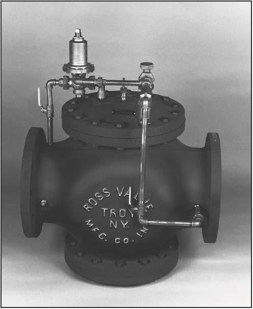
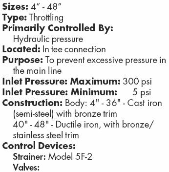
1 SUBMITTAL NOTES PROJECT: Ross Model 50RWR-A Pilot Operated Surge Relief Valve with Hydraulic Anticipation Size: inch / mm Every Ross Valve shall be hydrostatically tested for body integrity and tight seating at the factory prior to shipment. Field operating conditions are simulated, and the controls are adjusted for proper operation. In order to design and test each valve under operating conditions similar to those in the field, please complete / confirm the following: Inlet (supply) pressure psi Valve relieves to [ ] Atmosphere / Drain [ ] Pump Suction at psi The Ross Globe Body Style Valve can be installed in any position. In order to properly design the valve and orient the controls, please confirm the physical layout of the installation. (** Designates standard valve orientation.) Valve inlet & outlet (flow) : [ ] Horizontal ** or [ ] Vertical Valve piston axis : [ ] Vertical ** or [ ] Horizontal [ ] Horizontal The valve shall be furnished with: ANSI B16.1 Class 250 cast iron body & cap, with: [ ] Class 125 flanges [ ] Class 250 flanges Internal metal parts - Bronze construction Ross Model 50RWR Hydraulic Pressure Relief Pilot Valve (part #19). Initial Setting (typically 15-20% above normal inlet pressure): psi. A Feature: Surge Control (Hydraulic Trigger). Ross Model 40WR Hydraulic Pilot Valve (part #30) used for Low Pressure Anticipation. Initial Setting (typically 20-25% below normal inlet pressure): psi. Ross Model 5F2 Strainer (part #25) with Stainless Steel Filter Element and Blow-Off Ross Standard Coarse-Thread Needle Valve (part #17) Isolation valves: 0.5" Ball Valves, Bronze/Stainless Steel (part #18) Position Indicator, Bronze (part #20) Red brass pipe fittings and rigid control piping Tapped ports with gauge cocks on inlet & outlet (gauges by others) PAINTING: Ferrous surfaces of valve shall be coated with ANSI/NSF Standard 61 Certified Epoxy (Tnemec Series FC20) - Meets the performance requirements of AWWA D102 Inside System No. 1. Operation & Maintenance Manual (shipped with the valve). [ ] Other (Code / Description) / (Please list any additional features that are required. A representative may need to contact you for any relevant operating data.) The valve will be constructed with materials and options stated on this notes page & cut view drawing & quote only, any changes or adders will be reviewed by Ross Valve Mfg. Co., Inc. with possible additional charges to quoted valve pricing. All information following the cut view drawing is for general information. Any special submittal requirements will be an additional charge to purchaser. The Ross Valve Mfg. Co., Inc. reserves the right to modify valve construction which will result in equal or superior performance to existing designs. These modifications may be made at any time and at the sole discretion of the manufacturer. ROSS VALVE MFG. CO., INC., TROY, NY PHONE FAX

2
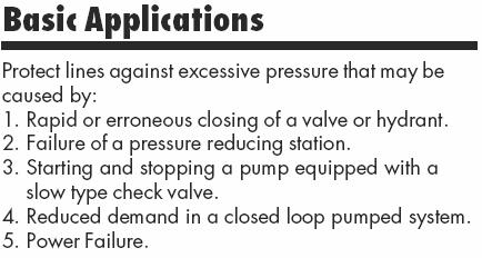
3 RELIEF VALVE Basic Applications Customized Features Basic Applications Protect lines against excessive pressure that may be caused by: 1. Rapid or erroneous closing of a valve or hydrant. 2. Failure of a pressure reducing station. 3. Starting and stopping a pump equipped with a slow type check valve. 4. Reduced demand in a closed loop pumped system. 5. Power Failure. If: Pressure in the supply/user line exceeds a preset acceptable pressure Ross Main Valve will: Discharge a sufficient amount of water to reduce pressure to the preset level. If: Pressure in the supply/user line drops to the preset pilot valve setting Ross Main Valve will: Close. A SUPPLY - Surge Control DISCHARGE USER Optional if pipe to atmosphere Primarily Controlled By: Hydraulic pressure (mainline) Located: Along external piping of the relief valve Purpose: To anticipate and minimize pressure waves SYSTEM COMPONENTS: Accumulator Drum: Sized according to need Drain Orifice Valves: Ball: Speed Control Pilot: Low pressure anticipating BASIC APPLICATION: Start relief valve open on a low pressure wave before the shock wave reaches the station. CUSTOMIZED CONTROL UNIT: Added to the relief valve external piping circuit to provide additional control over pressure in the operating chamber are: 1. External piping that extends from the operating chamber to the accumulator drum. 2. Accumulator - Collects water from the operating chamber and lets it slowly bleed out. 3. Drain orifice - Causes water to slowly bleed out of the accumulator. 4. Ball valve - Limits flow from the operating chamber into the accumulator. OPERATION: Because the surge control feature anticipates the surge, it automatically readies the valve in advance to react, thereby maintaining an acceptable pressure within the main line. 1. When line pressure falls, it activates the following cycle. a. When pressure drops to the low pressure valve setting, the valve opens and causes water to flow from the operating chamber into the accumulator where it bleeds out at a much slower rate than the water entering. b. Main line water, encountering decreased resistance, pushes the piston up, opening the main valve. c. Main valve remains open until the accumulator fills up and no more water can be transferred. (The accumulator is sized to insure the valve remains open until the high pressure wave has been relieved through the open valve.) 2. When line pressure exceeds the relief valve setting, a. The relief valve pilot overrides all other functions, causing the main valve to act like a standard relief valve. 3. When main line pressure has returned to normal, a. Water remaining in the accumulator continues to discharge into the atmosphere until the accumulator is empty. b. The main valve acts like a basic relief valve. CAUTION: It is important not to oversize valves because they usually go wide open. ACAV - Anti-Cavitation Seat Trim Located: Inside the main valve Purpose: To provide protection against cavitation damage to the internals of the valve BASIC APPLICATION: To control potential cavitation in a column of water, away from the valve's surfaces. BR - 10 Factory: Telephone (518) ; Fax (518)

4 P.O. BOX 595, TROY, NEW YORK TEL FAX IMPORTANT To ensure proper operation of this relief valve, the controls of the valve must always be supplied with a positive pressure source. This positive pressure source is particularly important for installations where the relief or surge control valve is discharging to atmosphere or near atmospheric pressures. Low pressure conditions typically associated with a relief valve occur when the valve opens during start-up, test, or during a high pressure surge. Adequate testing should be performed on this valve and system to assure a low pressure condition will not occur during a surge condition. The system should be tested with the relief valve open. Supply pressure to the control piping should not fall below approximately 20 psi. With the valve open and discharging water, the valve should be able to close automatically as water is reintroduced into the controls. If the valve does not close, the controls should be piped to a positive pressure source. If a low pressure condition exists, the contractor or user should run a separate source of water pressure to the controls of the valve. A separate pressure source can typically be obtained from a header or similar location in the system where the line pressure is stable throughout the operation of the relief valve. ROSS VALVE MFG. CO., INC.
5 6 OAKWOOD AVENUE - TROY, NEW YORK, TEL. (518) POST OFFICE BOX TROY, NEW YORK, FAX (518) WEBSITE: 50RWR-A - Model 50RWR-A SURGE CONTROL VALVE WITH HYDRAULIC ACTUATION sales@rossvalve.com 5/15/00 RJC 37A
6 DIMENSIONS Globe Body Minimum Clearances Piston Valve Sizes: 4-48" Size (Inches) " 48" O P 4 1 / / / Note 1. Dimension O is clearance for removal of the top cap and piston for repacking the main valve. Additional working space for the convenience of the service man should be considered above as well as around the valve. 2. Dimension P as listed is the desirable clearance under the valve for removal of the STANDARD bottom cap. This dimension may be reduced to 1 inch for all valves on special applications. Note A. Do not obstruct vent hole located at the center of the bottom cap. B. Consideration should be given for installation of valves 14 or larger under manhole in the roof of the valve vault or for additional clearance above the valve since a mechanical hoist will probably be required for removal of the piston. An eye bolt or hook cast in the cover slab over the center of the valve is useful. C. If clearance under the valve is limited, dimensions O and P can be modified. Consult the factory concerning special applications. Factory: Telephone (518) ; Fax (518) EN - 15
7 The purpose of a pilot valve is to control the opening and closing of the main valve by trapping or releasing water from the main valve's "operating chamber" ("K" - the chamber above the main valve piston). The Model 50RWR Relief or Back Pressure Sustaining Pilot Valve uses this logic in order to control pressure upstream of the main valve. The pilot valve operates by creating a pressure balance across the diaphragms (#9). Pressure above the diaphragms is set by the adjusting screw (#2) acting on the springs (#6). Pressure beneath the diaphragms is exerted hydraulically via a separate sensing port directly under the diaphragms, from a remote inlet pressure source. When the pilot valve senses a low inlet pressure, the force of the springs (#6) causes the diaphragms (#9) and entire stem assembly to move down. This pushes the pilot seat packing (#19) into the seat, trapping water in the main valve operating chamber. This causes the piston of the main valve to close, resulting in an increase in the upstream pressure. Once the upstream pressure rises above the setting of the springs (#6), the hydraulic force overcomes the spring force and the stem assembly is pulled upwards by the attached diaphragms (#9). This causes the pilot seat packing (#19) to come off of its seat, releasing water from the main valve operating chamber. This causes the piston of the main valve to open, resulting in a decrease in the inlet pressure. This opening and closing sequence (commonly referred to as "throttling") is continuously taking place in order to control the inlet pressure of the main valve.
8 The purpose of a pilot valve is to control the opening and closing of the main valve by trapping or releasing water from the main valve's "operating chamber" ("K" - the chamber above the main valve piston). The Model 40WR Pressure Reducing Pilot Valve uses this logic in order to maintain a constant pressure downstream of the main valve. The pilot valve operates by creating a pressure balance across the diaphragms (#10). Pressure above the diaphragms is set by the regulating screw (#3) acting on the adjusting springs (#7). Pressure beneath the diaphragms is exerted hydraulically in one of two manners: 1 - A sensing port through the stem (#18) to the outlet throat of the pilot valve, or 2 - A separate sensing port directly under the diaphragms, from a remote outlet pressure source. When the pilot valve senses a low outlet pressure, the force of the springs (#7) causes the entire stem assembly to move down. This pushes the seat packing (#16) away from the seat, allowing water to escape from the main valve operating chamber. This causes the piston of the main valve to open, resulting in an increase in the downstream pressure. Once the downstream pressure rises above the setting of the springs (#7), the hydraulic force overcomes the spring force and the stem assembly is pushed upwards. This causes the pilot seat to seal off, trapping water in the main valve operating chamber (with water still entering through the inlet line). This causes the piston of the main valve to close, resulting in a decrease in the outlet pressure. This opening and closing sequence (commonly referred to as "throttling") is continuously taking place in order to maintain a constant outlet pressure.
 from the top and passes out through the sides of the cylinder. 2.")
9 Sizes: ½ 1 Located: On any external piping Purpose: To protect external piping and control devices from fouling or damage from foreign particles Screen: Cylindrical Dutch weave stainless steel wire mesh Piping Connection: Standard pipe thread Operation 1. Water enters the cylindrical screen (#2) from the top and passes out through the sides of the cylinder. 2. Any particle too large to pass through.012 inch openings gets trapped in the cylinder, where, unless there is unusual turbulence, they settle at the bottom. Recommendation 1. Strainer should be blown down frequently to remove collected foreign material from the sediment chamber. 2. Strainer screen should be removed occasionally for inspection and thorough cleaning. PARTS FLOW 1. Body Bronze 2. Screen Stainless Steel 3. Cap Gasket Rubber 4. Cap Brass 5. Flushing Cock Brass Note 1. To clean without shutting down the line, open the flush cock (#5) in the bottom cap (#4) for several seconds. 2. To remove the screen (#2), which requires shutting down the line, unscrew the bottom cap assembly (#5). Model Number: 5F-2 Option Two strainers installed in parallel (with the appropriate isolation valves) to permit uninterrupted service while cleaning. Sizes: One size fits all piston valves Primarily Controlled By: Manually Adjusted Located: On external control circuit of the main valve Purpose: To limit flow in and out of the operating chamber Standard Shipped Adjustment: Course Needle: 5/6 to 2 turns off the seat Fine Needle: Based on individual specifications PARTS 1. Lock Brass 2. Cap Bronze 3. Cap Gasket Rubber 4. Needle Brass 5. Body Bronze Operation The simple construction reliably limits maximum flow through the external piping, depending on the position of the adjustable stem/needle (#4) relative to the seat. 1. When the needle (#4) is adjusted counter-clockwise to a raised position, a. More water can pass through the needle valve. b. Water enters (leaves) the operating chamber more quickly. c. The main valve piston moves up and down more quickly. 2. When the needle (#4) is adjusted clockwise to a lowered position, a. Less water can pass through the needle valve. b. Water enters (leaves) the operating chamber more slowly. c. The main valve piston moves up and down more slowly. Adjustment To adjust needle valve, which can be done without shutting down the main valve: 1. Remove the hex cap (#2) and lock(#1). 2. With a screw driver; a. Turn the needle (#4) counter-clockwise to raise it b. Turn the needle (#4) clockwise to lower it 3. Once the optimum position is determined, no further adjustment of the needle should be required. Note It is advisable to occasionally remove the cap (#2) and lock (#1) and change the position of the needle (#4) momentarily to insure against gradual plugging. Option Two separate needle valves on one main valve Provides independent control of opening and closing speeds.
DOUBLE ACTING ALTITUDE VALVE. INSTRUCTIONS Installation - Operation - Inspection - Maintenance
 DOUBLE ACTING ALTITUDE VALVE INSTRUCTIONS Installation - Operation - Inspection - Maintenance 4" - 36" ROSS MODEL - 40DAWR Double Ac ting Altitude Valve Globe Flat Seat Style ROSS VALVE Mfg. Co., Inc.
WW-730. Pressure Sustaining/Relief Control Valve
 WW-730 Pressure Sustaining/Relief Control Valve Installation Operation & Maintenance Page 1 of 6 1. DESCRIPTION The Model 730 Pressure Relief / Sustaining Valve is an automatic control valve designed to
WW-720. Pressure Reducing Control Valve
 WW-720 Pressure Reducing Control Valve (Size Ranges: 2-4 and 6-14 ) Installation Operation & Maintenance Page 1 of 6 1. DESCRIPTION The Model 720 Pressure Reducing is an automatic control valve (powered
WW-720. Pressure Reducing Control Valve
 WW-720 Pressure Reducing Control Valve (Size Ranges: 2-4 and 6-14 ) Installation Operation & Maintenance Page 1 of 6 1. DESCRIPTION The Model 720 Pressure Reducing is an automatic control valve (powered
Installation Operation Maintenance. Bermad Level Control Valve with Modulating Horizontal Float Pilot valve One Way Flow IOM.
 Bermad Level Control Valve with Modulating Horizontal Float Pilot valve One Way Flow Model: FP 450-80 Installation Operation Maintenance PAGE 1 OF 5 1. Safety First BERMAD believes that the safety of personnel
Operation & Maintenance Manual Place this manual with valve or person responsible for maintenance of the valve
 Operation & Maintenance Manual Place this manual with valve or person responsible for maintenance of the valve Model CYCLE GARD II, CI & CNA YOUR PRODUCT INFORMATION: Model Number: Date: Serial Number:
Bermad Pressure Reducing. Model: 42T
 Bermad Pressure Reducing Pilot Operated Pressure Control Valve Model: 42T Installation Operation Maintenance Manual (IOM) REV. 27.7.17 Page 1 of 12 Safety First BERMAD believes that the safety of personnel
Cash Valve TYPE KP PILOT OPERATED BACK PRESSURE VALVE. ISSUED - DECEMBER 2000 CAVMC-0518-US-0208 ISO 9001 Certified
 Cash Valve PILOT OPERATED BACK PRESSURE VALVE ISSUED - DECEMBER 2000 CAVMC-0518-US-0208 ISO 01 Certified KP HIGH CAPACITY PILOT OPERATED BACK PRESSURE VALVE DESCRIPTION The Cash Valve Type KP is a pilot
Type S301 & S302 Gas Regulators INTRODUCTION INSTALLATION. Scope of Manual. Description. Specifications. Type S301 and S302. Instruction Manual
 Fisher Controls Instruction Manual Type S301 & S302 Gas Regulators October 1981 Form 5180 WARNING Fisher regulators must be installed, operated, and maintained in accordance with federal, state, and local
SINGER MODEL 106/206-RPS-L&H
 DESCRIPTION: Model 106/206-RPS-L&H dissipates surges caused by power failure to pumps. The valve anticipates the surge by opening on low line pressure associated with sudden stopping of pumps. This assures
Model: 720-UL INSTALLATION OPERATION MAINTENANCE. Bermad Pressure Reducing Valve IOM. Model: FP -720-UL Sizes: 2"-12" BERMAD. Application Engineering
 Bermad Pressure Reducing Valve Model: 720-UL INSTALLATION OPERATION MAINTENANCE Application Engineering BERMAD 1. Safety First BERMAD believes that the safety of personnel working with and around our equipment
Model: 43T. Bermad Pressure Relief Valve
 Model: 43T Bermad Pressure Relief Valve Installation Operation Maintenance Manual () Rev.C1_01.08.17 Page 1 of 10 Safety First BERMAD believes that the safety of personnel working with and around our equipment
BERMAD Waterworks. Level Control Valve with Altitude Pilot. 700 Series. Model X. Features and Benefits. Major Additional Features
 Level Control Valve with Altitude Pilot High level reservoirs & water towers Energy cost critical systems Systems with poor water quality Inherent refreshing Level sustaining at reservoir outlet The Level
TECHNICAL DATA. Page 1 of 12
 Page 1 of 12 1. DESCRIPTION The Viking Regulating Valve is a direct-acting, single-seated, spring-loaded diaphragm valve. When installed as a pilot regulating valve on a Viking Model H or J Flow Control
I T T Pressure Reducing Valve WARNING INSTALLATION, OPERATION, AND MAINTENANCE MANUAL
 INSTALLATION, OPERATION, AND MAINTENANCE MANUAL I-867-4T 867-4T Pressure Reducing Valve HANG THESE INSTRUCTIONS ON THE INSTALLED VALVE FOR FUTURE REFERENCE WARNING Read and understand all instructions
End Connection. Thread x Thread N/A N/A N/A N/A Flange x Flange N/A
 Worldwide Contacts www.tyco-fire.com Model RV-1 Pressure Relief Valve, Pilot-Operated, Globe and Angle Body Styles General Description Valves, through inch (DN50 through DN00), are factory assembled and
TECHNICAL DATA. Q = C v P S
 Page 1 of 13 1. DESCRIPTION The Viking 6 Model G-6000 Dry Valve Riser Assembly consists of a small profile, light weight, pilot operated valve that is used to separate the water supply from the dry sprinkler
Installation and operation Manual. Bermad Surge Anticipation Valve. Model No 435
 Instruction manual Bermad surge anticipation manual Model No 435 Installation and operation Manual Bermad Surge Anticipation Valve Model No 435 Bermad Water Technologies Rev 0 5/05/2015 7 Inglewood Drive,
1805 Series Relief Valves
 Instruction Manual Form 1211 1805 Series October 2011 1805 Series Relief Valves! WARNING Failure to follow these instructions or to properly install and maintain this equipment could result in an explosion
1200B2 Series Service Regulators. Instruction Manual
 00B Series Service Regulators Instruction Manual 00B Series Service Regulators 0 Elster American Meter 00B Series Service Regulators General Information The 00B Series Service Regulators are available
BACK PRESSURE / SUSTAINING
 In many liquid piping systems, it is vital that line pressure is maintained within relatively narrow limits. This is the function of the 108 Pressure Relief / Back Pressure Series of the OCV control valves.
V43 Pressure Actuated Water Regulating Valve
 FANs 125, 121 Product/Technical Bulletin V43 Issue Date 0996 V43 Pressure Actuated Water Regulating Valve The V43 Pressure Actuated Water Regulating Valves are designed to regulate water flow for water-cooled
BACK PRESSURE / SUSTAINING
 SPECIFICATIONS DIMENSIONS In many liquid piping systems, it is vital that line pressure is maintained within relatively narrow limits. This is the function of the 108 Pressure Relief / Back Pressure Series
CAST IRON VALVES FLOAT VALVE
 CAST IRON VALVES FLOAT VALVE NETAFIM CAST IRON VALVES FLOAT VALVE INLINE 25-400MM ANGLE 50-100MM SPECIFICATIONS Manufactured to ISO 9001 Available Valve sizes INLINE Flanged 50mm to 600mm & Threaded 19mm
CASH VALVE TYPE KP BACK PRESSURE VALVES
 A high capacity pilot operated back pressure valve that offers accurate control and dependable protection against overpressure conditions FEATURES Automatically maintains maximum pressure in a vessel or
BERMAD Waterworks. Pressure Reducing Valve. 700 Series. Model 720. Features and Benefits. Major Additional Features
 Pressure Reducing Valve Flow and leakage reduction Cavitation damage protection Throttling noise reduction Burst protection System maintenance savings The Pressure Reducing Valve is a hydraulically operated,
627 Series Pressure Reducing Regulators
 627 Series Pressure Reducing Regulators Introduction The 627 Series direct-operated pressure reducing regulators (Figure 1) are for low and high-pressure systems. These regulators can be used with natural
TECHNICAL DATA Q= C. Table 1 - Specifications
 September 25, 2013 Pressure Regulation 537a 1. Description The Model B-3 Pilot Operated Pressure Control Valve is a factory assembled unit. The unit consists of a Model J-2 Halar coated Flow Control Valve,
Ø248 Ø Series. R 2.00 R 2 Hydraulic Control Valves R 3 R 6 SEE "SEAT DE T DETAIL NO. 2" CONTROL VALVES
 Ø290 Ø248 Ø240 RAM Ø201 400 Series R 2.00 R 2 Hydraulic Control Valves R 3 G 50 92 30 R 6 SEE "SEAT DE T DETAIL NO. 2" Ø290 Ø248 Ø240 Ø201 30 i n d e x How To Order R 2.00 R 2 2 Company profile 4 Hydraulic
TECHNICAL DATA. Pressure Regulation 531a. April 24, 2009
 April 24, 29 Pressure Regulation 531a 1. DESCRIPTION The Viking Regulating Valve is a direct-acting, single-seated, spring-loaded diaphragm valve. When installed as a pilot regulating valve on a Viking
BERMAD Waterworks. Pressure-Reducing Valve. 700 Series. Model 720. Features and Benefits. Major Additional Features
 Pressure-Reducing Valve Flow and leakage reduction Cavitation damage protection Throttling noise reduction Burst protection System maintenance savings The Pressure-Reducing Valve is a hydraulically-operated,
Model 420-HY Pressure Regulating Hydrant Valve
 Model 420-HY Pressure Regulating Hydrant Valve INSTALLATION OPERATION MAINTENANCE 1. Safety First BERMAD believes that the safety of personnel working with and around our equipment is the most important
Regulator from 1800 B series
 Regulator from 1800 B series Regulator from 1800 B series Measuring of industrial gases frequently requests a precise pressure regulation for the purpose of dosage and proccesing. UNIS FAGAS has two kinds
TECHNICAL DATA CAUTION
 Page 1 of 12 1. DESCRIPTION The Viking Model C-2 Pilot Pressure Regulating Valve is a direct-acting, single-seated, spring-loaded diaphragm valve. When installed as a pilot regulating valve on a Viking
FUNDAMENTALS OF PRESSURE REGULATORS ROBERT BENNETT MANAGER OF TRAINING ELSTER AMERICAN METER
 FUNDAMENTALS OF PRESSURE REGULATORS ROBERT BENNETT MANAGER OF TRAINING ELSTER AMERICAN METER SUPPLY = DEMAND FUNCTION OF A REGULATOR A regulator may be defined as a "mechanism for controlling or governing
TECHNICAL DATA. the Viking Pilot Pressure Regulating Valve 1 Model A-1 Speed Control Assembly: OBSOLETE. the Viking Speed Control Assembly 1
 November 30, 1994 534 a 1. PRODUCT NAME VIKING 2" (50mm), 3" (75mm), 4" (100mm), 6" (150mm) 2. MANUFACTURER THE VIKING CORPORATION 210 N. Industrial Park Road Hastings, Michigan 49058 U.S.A. Telephone:
TECHNICAL DATA Q = C. v P S. 2 Model G-2000 Dry valve. Page 1 of 13
 Page 1 of 13 1. Description The Viking 2 Model G-2000 Dry Valve Riser Assembly consists of a small profile, light weight, pilot operated valve that is used to separate the water supply from the dry sprinkler
TECHNICAL DATA 3 MODEL G-3000 DRY VALVE RISER ASSEMBLY
 Page 1 of 13 1. DESCRIPTION The Viking 3 Model G-3000 Dry Valve Riser Assembly is equipped with a small profile, light weight, pilot operated valve that is used to separate the water supply from the dry
Welker Sampler. Model GSS-1. Installation, Operation, and Maintenance Manual
 Installation, Operation, and Maintenance Manual Welker Sampler Model GSS-1 The information in this manual has been carefully checked for accuracy and is intended to be used as a guide to operations. Correct
TECHNICAL DATA. Q= Cv S
 Page 1 of 13 1. DESCRIPTION The Viking 4 inch Model G-4000 Dry Valve Riser Assembly consists of a small profile, light weight, pilot operated valve that is used to separate the water supply from the dry
1800C and 1800C-HC Series Service Regulators
 1800C and 1800C-HC Series Service Regulators Installation Instructions www.elster-americanmeter.com General Information: The 1800C and 1800C-HC Regulators are available as Full Capacity Internal Relief
LAKOS Waterworks. PWC Series Sand Separators. Installation & Operation Manual LS-829 (10/12)
") LAKOS Waterworks PWC Series Sand Separators Installation & Operation Manual LS-829 (10/12) Table of Contents Separator Operation... 3 Individual Model Details.... 4 Flow vs. Pressure Loss Chart 4 Installation
LAKOS Waterworks PWC Series Sand Separators Installation & Operation Manual LS-829 (10/12) Table of Contents Separator Operation... 3 Individual Model Details.... 4 Flow vs. Pressure Loss Chart 4 Installation
TECHNICAL DATA. TRIMPAC Model B-5 & B-5B
 September 16, 2013 Trimpac 250a 1. DESCRIPTION DEsCRIPTIoN is a factory assembled trim package for a ed an electric/pneumatic release module in a metal enclosure. The standard trim normally required on
MWEA MAINTENANCE SEMINAR SPECIALTY VALVES POWER GLOBES
 MWEA MAINTENANCE SEMINAR SPECIALTY VALVES POWER GLOBES J O H N G. H U N T E R Types of Valves P A U L M A R C H I Accessories Principals of Operation Maintenance Control Valve Types Common Problems Key
Model GPR Primary Pressure Regulating Valve. Instruction Manual
 Model GPR-2000 Primary Pressure Regulating Valve Instruction Manual Please read this instruction manual thoroughly before using the primary pressure regulating valve, so that you may do so correctly and
299H Series. Introduction. P.E.D. Categories. Specifications. Installation. Warning. Installation Guide English September 2012
 Installation Guide English September 2012 299H Series Introduction This Installation Guide provides instructions for installation, startup, and adjustment of 299H Series regulators. To receive a copy of
BERMAD Waterworks. Level Control Valve. with Bi-Level Vertical Float. 700 Series. Major Additional Features. Features and Benefits.
 Level Control Valve with Bi-Level Vertical Float Reservoir filling Very low supply pressure Low noise generation Energy cost critical systems Systems with poor water quality Reservoir outlet Distribution
RS(H)10,15 USER MANUAL. Read the complete manual before installing and using the regulator.
10,15 USER MANUAL. Read the complete manual before installing and using the regulator.") RS(H)10,15 USER MANUAL Read the complete manual before installing and using the regulator. WARNING INCORRECT OR IMPROPER USE OF THIS PRODUCT CAN CAUSE SERIOUS PERSONAL INJURY AND PROPERTY DAMAGE. Due to
RS(H)10,15 USER MANUAL Read the complete manual before installing and using the regulator. WARNING INCORRECT OR IMPROPER USE OF THIS PRODUCT CAN CAUSE SERIOUS PERSONAL INJURY AND PROPERTY DAMAGE. Due to
Speed control assembly model A-1
 Pressure Regulation 533a 1. DESCRIPTION The Viking Speed Control Assembly provides adjustment of the opening speed of Viking Deluge Valves, and adjustment of both the opening and closing speed of Viking
TECHNICAL DATA. Trimpac 251a. Spetember 16, 2013
 Spetember 16, 2013 Trimpac 251a 1. DEsCrIpTION DESCRIPTION TRIMPAC Model B-6 and B-6B is a factory assembled trim package for a double interlocked preaction system with an electric/pneu-lectric release
Pressure Independent Control Series
 Document No. 155-522 Pressure Independent Control Series Two-Way Cast Iron Flanged Bodies, ANSI 125 and 250 Description Siemens Pressure Independent Control Valves integrate three functions into a single
Types 749B and R130 Changeover Manifolds
 Instruction Manual MCK-1179 Types 749B and R130 June 2012 Types 749B and R130 Changeover Manifolds TYPE HSRL-749B TYPE 64SR/122 TYPE R130/21 TYPE 749B/21 Figure 1. Changeover Manifolds and Regulator Assemblies
Pressure Reducing Control Valve w/ Hydraulic Check Feature
 PERTIN INSTRUTINS peration The BEE Model PR- Pressure Reducing ontrol alve with Hydraulic heck eature is a pilot controlled diaphragm valve designed to reduce a fluctuating higher upstream pressure to
Mounting and operating instructions EB 2530 EN. Self-operated Pressure Regulator. Pressure Reducing Valve Type M 44-2
 Self-operated Pressure Regulator Pressure Reducing Valve Type M 44-2 Type M 44-2, connection G 1 4, K VS = 0.15 Type M 44-2, connection G 1, K VS = 6 Fig. 1 Type M 44-2 Pressure Reducing Valve Mounting
TECHNICAL DATA MAINTENANCE AIR COMPRESSOR MODEL G-1
 Dry 131h 1. DESCRIPTION The Viking Model G-1 Maintenance Air Compressor is an electric motor-driven, aircooled, single-stage, oil-less compressor. The unit is equipped with a check valve and provides a
Types S100K and S102K Pressure Regulators
 Instruction Manual Form 5624 Types S0K and S2K 01/01 Types S0K and S2K Pressure Regulators W7478-1 Figure 1. Types S0K and S2K Pressure Regulator Introduction Scope of Manual This manual provides instructions
TECHNICAL DATA. than the water inlet pressure to the concentrate
 Foam102a 1. DESCRIPTION The Viking Low Flow Foam/Water proportioning system, is a UL Listed and FM Approved system, for use with 3M foam concentrates. This system consists of a standard wet pipe sprinkler
TECHNICAL DATA. Trimpac 244a. September 16, 2013
 September 16, 2013 Trimpac 244a 1. DEsCrIpTION DESCRIPTION TRIMPAC Model B-1 and B-1B is a factory-assembled trim package with an electric release module in a metal enclosure. The standard trim normally
FILTER BYPASS CONTROL
 Differential Control Valve Series 110 The Series 110 Differential Control Valve is designed to accurately control the pressure difference between any two points. In some systems this means the valve remains
TECHNICAL DATA CAUTION
 Page 1 of 6 1. DESCRIPTION The Viking Model D-2 Accelerator is a quick-opening device, with an integral anti-flood assembly, used to increase the operating speed of a differential type dry pipe valve.
Waterous Relief Valve
 Operating Instructions 1. Reduce pump discharge pressure with engine throttle. Make sure four way (On/Off) valve is OFF. 2. Open at least one discharge valve. Accelerate engine until pressure gage indicates
DESIGN DATA A WET PIPE BLADDER TANK FOAM/WATER SYSTEM WITH HYDRAULICALLY ACTUATED DELUGE CONCENTRATE CONTROL VALVE
 February 9, 1998 Foam 101a A BLADDER TANK WITH 1. DESCRIPTION A Wet Pipe Bladder Tank Foam/Water System is a standard wet pipe automatic sprinkler system capable of discharging a foam/water solution automatically
Filling valves AL, ALM Series Automatic filling units ALOMDIW, ALOMDNW Series
 Filling valves AL, ALM Series Automatic filling units ALOMDIW, ALOMDNW Series Main features Designed for automatic filling of sealed heating systems and for protection of the water mains from risk of contamination.
Installation, Operation and Maintenance Manual for Back Pressure Regulator
 Installation, Operation and Maintenance Manual for Back Pressure Regulator Model 8860 2009 Groth Corporation IOM-8860 Rev. B 12541 Ref. ID: 95565 Page 2 of 13 Table of Contents I. INTRODUCTION 3 II. DESIGN
INSTALLATION INSTRUCTIONS. CVS 67CFR Pressure Reducing Instrument Supply Regulator INTRODUCTION
 INSTALLATION INSTRUCTIONS CVS 67CFR Pressure Reducing Instrument Supply Regulator INTRODUCTION The CVS Controls 67CFR Filter regulator is a pressure reducing supply regulator typically used for pneumatic
Models 106-RF / 206-RF Rate of Flow Control Valve
 Rate of Valve KEY FEATURES Accurately limits low to a pre-set maximum Easily adjustable low limit Paddle-style oriice plate included Optional oriice plate housing 106-RF Globe Product Overview The 106-RF
Description. Functions. Technical data. Applications. Tests. On-Off 2 levels float control valve, closing at high level and opening at low level.
 DN 0 to 1000 - Serie K3 0 On-Off levels float control valve, closing at high level and opening at low level. Functions Prevents overflowing and closes at a constant and adjustable high level. Remains closed
Anti-flood device Model B-1
 December 4, 2009 Dry Systems 123a 1. DESCRIPTION The Anti-flood Device is required when Viking accelerators are installed on dry systems according to Viking Model E-1 Accelerator Trim Charts. In the SET
Cash Valve TYPE G-4 PILOT OPERATED PRESSURE REDUCING REGULATOR FOR STEAM, AIR AND GASES. ISSUED - MARCH 2001 CAVMC-0512-US-0208 ISO 9001 Certified
 Cash Valve TYPE G-4 PILOT OPERATED PRESSURE REDUCING REGULATOR FOR STEAM, AIR AND GASES ISSUED - MARCH 2001 CAVMC-0512-US-0208 ISO 9001 Certified TYPE G-4 DESCRIPTION FIG 2042 - Bronze FIG 2043 - Bronze
Pressure Reducing Valve for Steam Type 2333 A
 Pressure Reducing Valve for Steam Type 2333 A Fig. 1 Type 2333 A 1. Design and principle of operation The pressure reducing valve consists of a balanced control valve and a closing actuator equipped with
Installation Troubleshooting Maintenance Instructions Installation / Start-up
 Model ZW207 Installation Troubleshooting Maintenance Instructions Installation / Start-up NOTE: Flushing of all pipe lines is to be performed to remove all debris prior to installing valve. 1. For making
Discharge Relief Valve Operation & Maint.
 Relief Valve Operation & Maint. CZ Series Centrifugal Fire Relief svalve Operation and Maintenance Instructions 1410 Operation and Maintenance Form No. F-1031 Section 2302.6 2111 Issue Date 04/90 11/95
TECHNICAL DATA SINGLE INTERLOCKED PREACTION SYSTEM WITH PNEUMATIC RELEASE
 1 of 10 1. DESCRIPTION (Refer to Figures 1-3.) Viking supervised Single Interlocked Preaction Systems utilize a Viking Deluge Valve and a pneumatically pressurized automatic sprinkler system. The system
Type ACE95jr Tank Blanketing Valve
 Instruction Manual Form 5666 Type ACE95jr 04/01 Type ACE95jr Tank Blanketing Valve W8157 Introduction Scope of Manual Figure 1. Type ACE95jr Tank Blanketing Valve This instruction manual provides installation,
TECHNICAL DATA. Table 1 - Specifications
 Page 1 of 6 1. DESCRIPTION Model A-3 Pilot Operated Pressure Control Valves are factory assembled units. Each unit consists of a Model H-2 Halar coated Flow Control Valve, a Speed Control Valve, a Model
KECKLEY INSTALLATION, OPERATING AND MAINTENANCE INSTRUCTIONS TYPE NO. 7 FLOAT VALVE
 INSTALLATION, OPERATING AND MAINTENANCE INSTRUCTIONS TYPE NO. 7 FLOAT VALVE APPLICATION/SERVICE: The NO. 7 internally piloted valves are recommended where tight closing is essential. The NO. 7 is most
Wet pipe low flow foam/water system
 December 6, 2010 Foam 14a 1. The Viking Low Flow Foam/Water proportioning system, is a UL Listed and FM Approved system, for use with Viking supplied foam concentrates. This system consists of a standard
SAN ANTONIO WATER SYSTEM I.H. 10 Ground Storage Tank Rehabilitation and Painting Project SAWS Job No Solicitation No.
 SAN ANTONIO WATER SYSTEM I.H. 10 Ground Storage Tank Rehabilitation and Painting Project SAWS Job No. 13-0118 Solicitation No. B-16-014-GC September 1, 2016 TO BIDDER OF RECORD: The following changes,
Discontinued. Powers Controls. Technical Instructions Document No P25 RV Rev. 1, May, RV 201 Pressure Reducing Valves.
 Powers Controls RV 201 Pressure Reducing Valves Description Features Product Numbers Dual Pressure PRV Technical Instructions Document No. 155-049P25 RV 201-1 Single Pressure PRV The RV 201 Pressure Reducing
TECHNICAL DATA PILOT PRESSURE REGULATED DELUGE SYSTEM CONTROLLED BY PNEUMATIC RELEASE. 1. DESCRIPTION (Refer to Figures 1, 2 or 3.
 Page 1 of 8 1. DESCRIPTION A Viking Pilot Pressure Regulated Deluge System utilizes a Viking Flow Control Valve to control water flow into the deluge system. The flow control valve must be installed with
Models 461-S, 461-8S and S Regulators. R-1330 Rev. 7
 Models 461-S, 461-8S and 461-12S Regulators R-1330 Rev. 7 461-S, 461-8S and 461-12S Regulators The Sensus Models 461-S, 461-8S and 461-12S are balanced valve, spring type regulators designed for distribution
my SYSTEM A guide to common applications in water distribution systems
 my SYSTEM A guide to common applications in water distribution systems WWW.SINGERVALVE.COM INDEX This short guide is intended to offer guidance on some of the common problems, applications and questions
TECHNICAL DATA ANTI-FLOOD DEVICE MODEL B-1 1. DESCRIPTION
 Page 1 of 6 1. DESCRIPTION The Model B-1 Anti-flood Device is required when Viking accelerators are installed on dry systems according to Viking Model E-1 Accelerator Trim Charts. In the SET condition,
Rate of Flow Valve Series 120
 SPECIFICATIONS Rate of Flow Valve Series DIMENSIONS The OCV Series 120 Rate of Flow control valve is designed to control or limit flow to a predetermined rate, regardless offl uctuations in downstream
SCA Series Inverted Bucket Steam Traps
 0770050/5 IM-P077-06 ST Issue 5 SCA Series Inverted Bucket Steam Traps Installation and Maintenance Instructions 1. General safety information 2. General product information 3. Installation 4. Commissioning
1800CPB2 Service Regulators Maximum Inlet Pressure 125 PSIG
 A C E D SB-8520.2 1800CPB2 Service Regulators Maximum Inlet 125 PSIG AMC Quality System QMI is Accredited by: C R E D I T ISO 9001 Certified Certificate #006697 R E ANSI RAB G I S T R A R Dutch Council
Bermad Model:
 Bermad Model: 405-02 Manually Operated Hydraulic Valve INSTALLATION OPERATION MAINTENANCE Application Engineering BERMAD 1. Safety First BERMAD believes that the safety of personnel working with and around
TECHNICAL DATA. Q = C v P S
 January 6, 2012 Preaction 348a 1. Description Viking supervised Surefire Preaction Systems utilize the Viking G-6000P Valve. The small profile, lightweight, pilot operated Viking G-6000P Valve comes complete
64 Series Pressure Reducing Regulators
 Instruction Manual Form 1245 64 Series March 2006 64 Series Pressure Reducing Regulators W1943 Figure 1. 64 Series Regulator Introduction Scope of Manual This manual provides instructions for the installation,
TECHNICAL DATA. Q = C v P S
 January 6, 2012 Preaction 333a 1. Description Viking supervised Surefire Preaction Systems Utilize the Viking G-3000P Valve. The small profile, lightweight, pilot-operated Viking G-3000P Valve comes complete
TECHNICAL DATA. Q = C v P S
 Preaction 346a 1. Description The 6 Model G-6000P Electric Release Preaction System Riser Assembly can be used as a Single Interlock Preaction System with Electric Release, or as a Double Interlock Preaction
Float Operated Level Controllers
 CONTENTS Float Operated Level Controllers IM0015 Nov. 2014 PAGE Introduction 1 Scope 1 Description 1 Specification 1 Control Installation 2 INTRODUCTION Side Mount Back Mount Prior to installing, the instructions
Pressure Regulator B-95
 Pressure Regulator B-95 TYPE B WATER & AIR TYPE B INTERIOR WATER & AIR B SERIES VALVES DESTRIPTION The Cash Valve Series B pressure reducing and regulating valves are single seated, spring loaded, direct
22. Specialty Valves.
 22. Specialty Valves. a. Types of Specialty Valves. 1) Use of the following specialty valves is covered in this section: Altitude Valve, Pressure Reducing Valve, Pressure Relief Valve, Swing Check Valve,
TITAN FLOW CONTROL, INC.
 PREFACE: This manual contains information concerning the installation, operation, and maintenance of Titan Flow Control (Titan FCI) Simplex Basket Strainers. To ensure efficient and safe operation of Titan
DS06D,G Dial Set Pressure Regulating Valve
 DS06D,G Dial Set Pressure Regulating Valve PRODUCT DATA FEATURES APPLICATION Built-in, factory-calibrated outlet pressure adjustment dial. Noncorroding unitized cartridge contains all working parts and
Model GP PRESSURE REDUCING VALVE Installation & Operation Manual
 Model GP-2000 PRESSURE REDUCING VALVE Installation & Operation Manual Please read this bulletin thoroughly before using the pressure reducing valve, so that you may do so correctly and safely. Please carefully
TECHNICAL DATA ACCELERATOR MODEL E-1
 Page 1 of 10 1. PRODUCT DESCRIPTION The Viking Model E-1 Accelerator is a quick-opening device. When installed with the required external Anti-flood Device, the assembly is designed to increase the operating
300 Series. Automatic Hydraulic Control Valves
 Automatic Hydraulic Control Valves AVFI Pty Ltd 54 Enterprise Drive Bundoora Vic 3083 p: 03 8467 0000 f: 03 8467 0099 e: avfi@avfi.com.au w: www.avfi.com.au 300 Series General 300 SERIES Automatic Hydraulic
KTM 50 (DN ) Installation, maintenance and operating instructions
 Installation, maintenance and operating instructions") 52 762-306 09.2014 KTM 50 (DN 100-200) Installation, maintenance and operating instructions General High-performing and compact, these pressure-independent control valves for variable flow heating and
52 762-306 09.2014 KTM 50 (DN 100-200) Installation, maintenance and operating instructions General High-performing and compact, these pressure-independent control valves for variable flow heating and