Deep Six Signature Regulator Technician Service Manual
|
|
|
- Caitlin Gilbert
- 5 years ago
- Views:
Transcription


1 Deep Six Signature Regulator Technician Service Manual
2 Copyright 2017 Deep Six Expedition Dive Gear Author UDM Consulting All rights reserved.
3 DEDICATION This manual is dedicated to those who choose to go the extra distance and take responsibility for themselves. Servicing your own gear is not rocket science. It does take patience, attention to detail, a bit of training, and the right tools. For those explorers who choose to take this path, deep six salutes and thanks you for your support and loyalty. Deep six expedition dive gear is proud to provide you with the tools you need to explore the world most never see.
4
5 CONTENTS overview I 1 Tool List 1 2 Service Tips and concerns 2 3 Pre-service testing 6 4 First stage disassembly 12 5 First stage assembly 23 6 First stage testing 32 7 Second stage disassembly 35 8 Second stage assembly 41 9 Second stage testing Schematics Service kits Trouble shooting
6
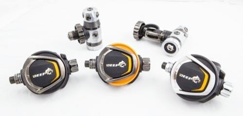
7 Overview The Deep Six Signature Regulator series consists of high performance components designed and manufactured to the exacting quality standards. They are suitable for use on the most demanding technical dives, as well as any dive within recognized recreational limits. From simple reef and quarry/lake dives to expedition level cave and wreck dives, these components will deliver superior performance and reliability. The first stage, that reduces the pressure of the SCUBA cylinder, supplies intermediate pressure through five ports. Four surrounding the perimeter of the turret, at strategically placed angles for optimum hose routing, and one in the end of the turret. Whether diving a single cylinder, back mounted doubles, or sidemount, the first stage will allow the diver to make the most efficient use of these ports when selecting hose lengths for their particular needs. Two high pressure (HP) ports on either side of the regulator body are placed at 90 degrees to the body to allow for better routing of the SPG s in either back mount or sidemount configurations. The first stage is a balanced diaphragm style first stage. A balanced diaphragm system maintains a constant volume of air to the second stages as cylinder pressure decreases and as depth increases. When properly tuned and functioning a balanced diaphragm first stage will have the same ease of breathing throughout the dive regardless of cylinder pressure and depth. The Deep Six Signature Series excels in this. The second stages are also balanced and adjustable for breathing effort. They make use of a breathing adjustment knob to allow the user to adjust breathing resistance. This allows the user to set the resistance level (cracking pressure) where the second stage starts to deliver air. The second stages have venturi levers for reducing the risk of free flows in the event the stage is dropped. In the forward pre-dive position, the lever directs a supply of air to the inside face of the main second stage diaphragm. This has the effect of pushing the diaphragm out and allowing the lever to return to its normally closed position. In the rearward dive position the air supply is allowed to travel to the mouthpiece opening unrestricted. The second stage makes use of a newly designed turbo poppet that provides a venturi effect in the air barrel for more efficient air flow and easier breathing.
8 In the following pages will be found, the disassembly, assembly, tuning, and troubleshooting steps for these components. Photos are used throughout to illustrate the procedures. Please pay special attention to all critical points! Whenever an item of extra importance needs to be observed a Critical Point: will appear followed by the necessary information. See below. Critical Point: It is important that this be read and followed! Included in this manual is a list of recommended/required tools for each disassembly, assembly, and testing section for all components. They are identified in each section where they are used. The schematics, with part numbers, are located in the rear of this manual along with a general troubleshooting guide and at the end of each section is a blank page for notes. Throughout the text, parts are referenced using the item number on the schematic in order to facilitate easy location of each individual part. The schematics for the DIN and Yoke first stages use different ITEM numbers to identify the same part. In the text the DIN version will use a D in front of the item number to distinguish it from the Yoke version. A Y will be used to identify the Yoke drawing item number. Example (ITEM D10/Y12). viii
9 ix
10
11 1. TOOL LIST 1. Adjustable Torque Wrench 3/8 drive inch pounds range 2. In-line second stage adjustment tool ScubaTools recommended or 5mm hex wrench 3. Soft Jawed Vise 4. 1 st Stage Handle for HP and LP ports 5. 3/4 inch 3/8 th drive socket for Yoke assembly *use with item /16 inch 3/8 th drive socket 7. ScubaTools 3/8 th drive 3 inch extension SKU: mm 3/8-inch drive Hex Head male socket 9. 5mm hex head wrench 10. 4mm 3/8 drive hex socket Adjustable Wrenches 12. Brass Picks for removing O-rings 13. Intermediate Pressure Gauge 14. Magnahelic Gauge: 0 3 inches of water range or better 15. Christolube MCG 111 or Tribolube inch Pin spanner with.140 pin #6 ScubaTools (2 recommended) inch Pin Spanner with.140 pin #5 ScubaTools inch x 5-inch soft rubber pad 19. Soft Bristle Cleaning Brushes (Nylon) 20. Wooden or plastic dowels 1/8 3/16 diameter 1

12 2. General Service Concerns Before you commence the servicing of your Deep Six Signature Regulators, gather all the required tools, lubricant, service kits and clean the area. Ensure the service area is free of all distractions that may cause you to lose track of where you are in the service procedure. Address any environmental concerns that may cause problems during the servicing of your regulators. Examples of these would be family pets, children, airborne dust and dirt, and unexploded goats. Ensure that all required servicing/testing air supplies are available and at the proper test pressures, if not using a regulated supply from a single source. This would include the use of cylinders of compressed breathing air from a Grade E or better air supply. The Deep Six Signature Regulators are designed to be used with Air or Enriched Air Nitrox with oxygen concentrations up to 100% at 2400 PSI and 80% at 3400 PSI. As such, only Grade E or better breathing air should be used for testing and servicing of the regulators. In order to restore your Deep Six regulators to factory condition (O2 clean), oxygen cleaning and assembly procedures will be discussed in the cleaning and assembly chapters. This includes the cleaning solutions and appropriate personal preparations that are necessary. 2
13 Critical Point: Never use air from a non-breathing air source! Once the area has been made suitable for service and all required materials are present, servicing of the unit may begin. Cleaning of the disassembled components should be done using clean fresh water, a degreaser that leaves no organic residue (clear Simple Green, dye free Dawn dishwashing liquid, or Blue Gold Cleaner are suggested), and a method to remove any corrosion. This may include the use of an Ultrasonic Cleaner with a mix of 50/50 white vinegar to water or other suitable solution. An ultrasonic cleaner with a built-in heater is recommended. It is also recommended to use lint free cloths for drying excess water on the parts and final drying using compressed air. For regulators that are going to be used with Oxygen percentages above 40%, a UV light to detect the presence of organic contamination is strongly suggested. Use of this light will be covered in the first stage assembly chapter. Critical Point: Drying with low pressure compressed air should always be done while holding parts securely to avoid loss of parts being dried and to avoid pressure related injuries. NEVER USE HIGH PRESSURE TO DRY PARTS! *A note about using compressed air. In the USA, blowguns used in commercial applications (dive shop test bench for example) are regulated by the Occupational Health and Safety Administration (OSHA). Blowguns supplying more than 30 PSI at the outlet must be restricted to that level or have an outlet blockage device that allows excess pressure to vent safely. Usually accomplished by holes drilled near the tip that will direct the flow away from the blocked orifice. This is to prevent embolisms through the skin.* Once all components have been serviced and reassembled, in water testing in a controlled environment, such as a swimming pool, is highly recommended. This ensures that the unit is functioning properly. In water testing also helps to detect leaks and overall function of the system as a complete unit. Testing in a controlled environment is when you want to discover any service issues that may crop up. Deep Six does not recommend testing your regulator service prowess on a big dive! While following this manual, using only genuine Deep Six Service Kits, and paying close 3
14 attention to detail should ensure success in servicing your regulator, what you are doing is replacing soft parts. Those parts are tested to the highest quality standards, but failures are not unknown. Use common sense and be sure of your gear before taking it on any pinnacle or expedition level dives! Even if those expeditions are to your local quarry or shallow reef! Following bench and water testing the unit should be re-evaluated as noted in Chapter 3 to determine that all pressures are stable and all connections secure to ensure your safety and enjoyment. SCUBA diving is an extreme activity conducted in an alien environment. Don t take it lightly. Maintain your gear and yourself to the highest standards to ensure your safety. 4
15 5
16 3. Preliminary Testing Preliminary testing of the Deep Six Signature Regulator components is necessary to identify any issues with the components and verify overall regulator function. The preliminary testing will include: 1. Overall Visual Inspection 2. Detailed Inspection of Hoses 3. Detailed Visual Inspection of Instrumentation 4. Checking of Intermediate Pressure 5. Checking of Cracking Pressure and Negative Pressure Test 6. Integrity of 1 st Stage Body and Main Diaphragm Retainer 7. Second Stage Case Integrity Overall Visual Inspection This inspection is done to identify any issues that may affect the servicing of the unit. It is also done to ensure that pressurizing the system will pose no risk to the person servicing the regulator. The service technician will check all connections to make sure the second stages are secure on the hoses. The service technician will check that the hoses are secured on the first stage with no extruded O-rings. The service technician will ensure that there are no cracks in the SPG face. The service technician will ensure that the yoke or DIN assembly is secure and that the yoke knob is not damaged. DIN regulators require the servicing technician to inspect the captured DIN O-ring They will also inspect the filter for signs of discoloration indicating water intrusion or use of contaminated air. Detailed Inspection of Hoses This inspection is done to ensure that it is safe to pressurize the system without risk of hose rupture. The technician will check all hoses from end to end looking for evidence of bulging, splitting of the rubber outer casing, and dry rot indicated by cracking, stiffness, and flaking of the casing. 6


17 The technician will check all metal to rubber connections looking for evidence of separation, cracking, corrosion, or other defects. Any defects that are detected must be addressed before pressurizing the system to avoid injury to the service technician. The surest way to address this is to replace any questionable hoses. Critical Point: Any defects in a hose requires replacement of the hose before pressurizing the system! Failure to do so may result in serious injury or death! Once the hoses have been inspected and determined to be intact, the inspection process may continue. Detailed Visual Inspection of the SPG and connection The technician will check the SPG for any signs of cracking of the face, water intrusion, and corrosion around the SPG to hose connection. If using the Deep Six two gauge or three gauge console, it is necessary to remove the SPG from the boot. Soaking the console in warm water may aid in removing the compass. It will also aid in pushing the SPG out of the console to check the high-pressure spool between the SPG and hose. 7
18 The high-pressure spool should be removed from the connection and the O-rings inspected. Ideally they should be replaced or, if there is any sign of excess wear or corrosion, the spool and O-rings should be replaced as a unit. Replacing the spool is the usual course of action taken since it ensures that the entire assembly is new and safe. Critical Point: The high-pressure spool and O-rings are a dynamic connection and require liberal application of lubrication to ensure proper operation and service life! Following inspection of the SPG the depth gauge should be inspected for signs of cracks in the face, smooth operation of the maximum depth indicator, and that it is functioning properly. This can be done using a pressure vessel or by submerging the gauge in water deep enough to register a change. At this time, it is also advisable to clean and dry the console boot. Checking of Intermediate Pressure (IP) The Intermediate Pressure (IP) of the system should be checked only after the preceding checks have been done to ensure technician safety. Checking of intermediate pressure involves attaching an intermediate pressure gauge to the LP pressure inflator hose. The system is then pressurized by introducing high pressure air to the system through the 1 st stage yoke or DIN connection while partially depressing the purge button on one of the second stages. This is done in the event that the IP is too high. Depressing the purge button slightly on the second stage is done to prevent further damage to the system. Once the system has been pressurized the purge is released and the IP checked. Normal operating range for the system is with an IP of PSI. Ideally the system is operating at 135 PSI +/- 5 PSI. It should show no signs of creep or instability. Even though the unit will operate at the lower and higher ends of the acceptable range it should always be set for the optimal setting of 135 PSI with a 3000 PSI supply. Critical Point: Creep is demonstrated as the IP steadily increasing while the regulator is not in use. It is normal for the IP to drop 5-10 PSI during a breath or purge and then return to its operational setting. It is not normal for it to return to the setting and then continue to increase. This is usually a sign of a problem with the high-pressure seat. If the system shows no sign of creep or IP instability it is generally not necessary to rebuild the 1 st stage with some exceptions. 8
19 Critical Point: If the IP is stable but the unit shows signs of internal corrosion or the filter shows evidence of contamination the unit must be rebuilt! Other indications that the regulator may require rebuilding are small bubbles leaking from between the diaphragm retainer and main regulator body. Any sign of severe deformation of the environmental seal may also indicate a problem requiring service. Knowledge that the first stage has been flooded will also serve as notice that the unit must be rebuilt. Even fresh water contains dissolved minerals and other materials that, over time, may cause the regulator to malfunction due to internal corrosion. Once the IP has been checked and the additional items noted in the inspection of the first stage, the second stage operation may be checked. Checking of Cracking Pressure and Negative Pressure Test - The cracking pressure of both second stages is most accurately done with the use of a magnahelic gauge. It can also be done using a container of water and measuring the depth to which a stage can be submerged face down parallel to the water. This gives the technician an indication of the level of breathing effort at which the second stage will start to deliver air. Normal operational range for the adjustable second stage is 1.0 to 2.2 inches of water. Less cracking pressure on the lower end may be desired by the diver to reduce breathing effort. However, factory initial settings should be set at the 1.1 value to allow for break-in of the second stage low pressure seat. Over several dives it will not be uncommon to see this initial setting drop to 1.0 or even.9 on the magnahelic. The same observation is likely to be made on a newly serviced regulator. The negative pressure test is used to check the integrity of the main and exhaust diaphragms. This is done be turning the supply pressure off, purging the system, and attempting to take a normal breath from each second stage. The technician should be unable to draw any air through the second stages. If they are able to get a flow of air through them, the second stages should be removed from their hoses and the test repeated with a thumb over the hose opening to ensure the issue is with the second stage. If they are able to draw air through the stage, the main and exhaust diaphragms need to be carefully inspected for damage or deterioration. Debris, salt build up, sand, grit, and cracks in the case will also allow air to be drawn through the second stage when the hose opening is covered. Carefully check all of these. 9
 for setting the intermediate pressure.")
20 Integrity of First Stage Main Housing and Main Diaphragm Retainer The first stage body (ITEM D10/Y8) and main diaphragm clamp (ITEM D33/Y31) should be checked for obvious signs of damage. They should also be inspected for signs of corrosion between them. The main diaphragm clamp also houses the 6mm adjustment bolt (ITEM D32/Y30) for setting the intermediate pressure. This area and the interior of the ambient chamber between the main housing and main diaphragm clamp should be inspected for signs of corrosion or damage. This is accomplished by removing the environmental cap (ITEM D36/Y34) and silicone disc (ITEM D35/Y33), then removing the transpiston (ITEM D34/Y32). The environmental cap should only be hand tight. If it cannot be removed by hand, a number 6 pin spanner with.140 pin can be used to loosen it. If this is necessary, a second number 6 pin spanner should be used to hold the diaphragm clamp to keep it from coming loose. Critical Point: It is permissible, and advised, to use a small amount of lubricant on the threads of the environmental seal retainer. In addition the seal, transpiston, and environmental cap should be replaced while the regulator is pressurized! Once the cap has been hand tightened, the regulator can then be depressurized to ensure a proper seal. Second Stage Main Housing Integrity The integrity of the second stage main housing (ITEM 1) should be determined by looking for any obvious signs of damage. Scratches, gouges, missing parts, damaged exhaust ports, or loose cover retainer, or damaged cover may be indications that housing integrity has been compromised. 10
21 Perform the previously noted negative pressure test and test the operation of the purge cover. Look for cracks and/or missing sections. Operate the levers and adjustment knobs. They should move and turn smoothly with no sticking or feeling of grit being trapped in them. Any indication of a problem with housing integrity should be addressed before beginning the service process. A compromised housing may will affect final testing of the system. Critical Point: A damaged housing, purge cover, or diaphragm cannot be repaired. They must be replaced. After the technician has completed the preceding steps and identified those areas requiring service, the process of servicing the individual regulator components may begin. Environmental seal, main diaphragm clamp, turret body removal concern. When the 1 st stage is subjected to saltwater use on a regular basis, deposits of fine salt may lead to the environmental cap, main diaphragm clamp, and turret IP Cap (ITEM D21Y19) being hard to remove and require more than normal force to loosen. Should this be the case, the environmental cap can be removed after a dive outing, the threads cleaned, and a light coating of lubricant applied before replacing the cap while the regulator is pressurized. Then the regulator to should be depressurized after the seal is put back in place and the cap installed hand tight. If the regulator presents this condition during servicing, the best way to loosen the cap and clamp is to soak that part of the 1 st stage body in a solution of very warm water and white vinegar. Then using both pin spanners, place the regulator body on the rubber pad. Making sure it is secure, apply steady downward force on the spanners. Only in extreme circumstances should tapping of the spanners be required with a soft mallet while clamped in a bench vise. This method may necessitate replacement of the components due to the soft brass being deformed, therefore it should be avoided. 11

 if using the yoke version.")
22 4. First Stage Disassembly and Cleaning Disassembly of the 1 st stage Disassembly of the first stage is undertaken in the following steps after ensuring the system is depressurized if beginning the process on a bench valve or cylinder. Note the position of all hoses and port plugs document this. The easiest way to do this is to take a picture of the regulator system. Another acceptable method is to draw a diagram and keep that as a reference. Since it is likely you will only servicing your own regulators, this may or may not be an important consideration. Remove all hoses and port plugs. Remove the Yoke knob (ITEM Y1 ) if using the yoke version. Insert a first stage handle into the appropriate port and secure the handle in a vise with the environmental seal facing up to allow you to access the main spring adjustment bolt (ITEM D32/Y30). Remove the environmental seal cap (ITEM D36/Y34), silicone disc (ITEM D35/Y33), and transpiston (ITEM D34/Y32). If difficult to remove, refer to page 11. Unscrew the adjustment bolt at least 3 full turns to remove pressure on the mainspring (ITEM D31/Y29). 12


 making sure no parts drop out.")
23 Using the Pin Spanner, loosen the clamp (ITEM D33/Y31). Do not remove it entirely yet! If difficult to remove refer to page 11. Critical Point: Be sure there is no tension on the mainspring that may cause the diaphragm retainer to spring off of the 1 st stage body! Remove the 1 st stage from the vise and while holding the 1 st stage upside down, unscrew the diaphragm clamp(item D33/Y31) making sure no parts drop out. Set the clamp, adjustment bolt (ITEM D32/Y30), mainspring (ITEM D31/Y29), spring seat (ITEM D29/Y27), and plastic washers (ITEM D30/Y28) assembly aside. 13


.")
24 Remove the diaphragm (ITEM D28/Y26), and valve lifter (ITEM D27/Y25). Note: The diaphragm will be discarded. Under no circumstances is it to be re-used! Place the 1 st stage back in the vise diaphragm side down and perform the following operations: Using a number 5 pin spanner, remove the turret assembly by loosening the IP Cap (ITEM D21/Y19). Once loosened, unscrew it from the main body. If difficult to remove refer to page
,")
, and the two O rings (ITEM D22 and")


25 Using an 8 mm hex disassemble the turret to reveal the Teflon washer (ITEM D20/Y18), Swivel Retainer (ITEM D19/Y17), turret (ITEM D24/Y22), and the two O rings (ITEM D22 and 23/Y20 and 21) that seal the turret. Remove the O rings from the turret and place them with the old parts to be replaced. Using a 4mm hex socket, loosen the balance plug (ITEM D18/Y16). 15

 from the body.")

26 Having loosened the plug, remove the 1 st stage from the vise and turn the body diaphragm side up. Remove the balance plug from the main body. Remove the turret O-ring (ITEM D13/Y11) from the body. Set the balance plug/high Pressure seat (ITEM D14/Y12) assembly aside. Secure the regulator body using the 1 st stage tool in the vise with the yoke or DIN fitting facing up. 16


27 Use the ¾ socket and 3-inch extension to loosen the yoke retainer (ITEM Y4). Remove the yoke retainer. The yoke retainer also contains the filter (ITEM Y5) and filter O-ring (ITEM Y6). Set these aside. If using the DIN version perform the following steps: Using the first stage handle, clamp the stage in a vise DIN fitting facing up as pictured below. Loosen and remove the DIN retainer (ITEM D3) with a 6 mm hex wrench. Remove the O-rings (ITEM D2 and D12) from the DIN retainer. 17
.")
, filter O-ring (ITEM D8)")

28 Remove the DIN wheel (ITEM D5) and set it aside with the DIN retainer. With a 13/16 wrench or deep socket loosen the DIN housing (ITEM D6). Remove the DIN housing. The DIN housing holds the filter (ITEM D7), filter O-ring (ITEM D8) between the body and housing. Remove them and set them aside. They are replaced with the rebuild kit. Take the balance plug and remove the high-pressure seat (ITEM D14/Y12). Remove the valve spring (ITEM D16/Y14). 18


29 Using a brass or plastic pick, carefully remove the balance plug internal O-ring (ITEM D15/Y13), the thread O-ring (ITEM D17/Y15) on the bottom of the balance plug. Critical Point: Do not use a steel pick on the balance plug O-ring! Any scratch will compromise the inner surface and result in IP creep! If the inner surface is damaged in any way it must be replaced! This completes the disassembly of the 1 st stage. Carefully inspect all parts and separate the parts to be replaced from the non-replaceable parts. When inspecting the parts pay close attention to all threaded surfaces. Look for signs of corrosion, sand, silt, salt or other foreign materials. Using a magnifying glass and bright light, inspect the machined orifice and internal sealing surface of the balance plug. 19

 up to 2400 PSI and 80% O2 to 3400 PSI from the factory.")

30 All parts should be cleaned using a degreasing agent and clean water. Any corrosion should be dealt with using the white vinegar/water solution and the ultrasonic. Old lubricants are best dealt with before attacking any corrosion. Once the corrosion has been dealt with, re-clean all of the affected parts with the degreasing solution and rinse with clean fresh water. Using the Deep Six Signature Regulator with more than 40% Oxygen The Deep Six Signature regulator is suitable for use with pure Oxygen (100%) up to 2400 PSI and 80% O2 to 3400 PSI from the factory. To maintain this integrity during service of the 1 st stage it is necessary, prior to the final cleaning and rinsing step, to put on clean, powder-free, nitrile or latex gloves and from that point on handle all parts with gloves on until the 1 st stage is completely assembled. Critical Point: It is critical to ensure that no hydrocarbon contaminants are present on the work surface, tools, and that only oxygen compatible lubricants are used! Oxygen cleaning Cleaning your regulator for oxygen service is the next item we will address. In order to maintain oxygen service integrity careful attention must be paid to the following areas. Work station Before Oxygen cleaning of the regulator components takes place the work area must be clean and free of dirt, dust, and other contaminants. Clean, lint free towels and suitable covering should be used. Tools Assembly tools should be carefully washed using a suitable heavy perfume and dye free degreasing agent such as crystal Simple Green or Blue Gold Cleaner. Following this they should be rinsed in clean, fresh water and dried thoroughly. 20
31 Once cleaned and dried, ideally, they should only be handled with powder free clean nitrile or latex gloves and not removed from the work area until all service has been completed. Parts washing All non-replaceable parts should be cleaned in the following manner. Using a suitable degreasing agent, thoroughly clean all parts. A nylon brush works well for this. Rinse all parts with clean, fresh water. If you are unsure of your water quality, consider using distilled bottled water. Following the initial degreasing, remove any corrosion in an ultrasonic cleaner or scrubbing with a solution of 50/50 white vinegar and water. Next rinse the parts in clean fresh water. A clean colander/strainer or other container with the ability to drain greatly improves the rinse process since you can actually run water over them rather than soaking them. Before removing the parts from the water or container, don fresh gloves and wash your hands using the degreasing cleaner. Now remove the parts from the rinse and degrease them again while wearing the clean gloves. Rinse them to remove any traces of cleaner and set them on clean, lint free towels to soak up the excess water. Dry the parts with Oxygen compatible compressed air and set them on a clean surface. Inspect the parts with a UV light to look for traces of hydrocarbons. This will require you to dim the lights in order to do this. Another method is to use the water-break test. Fill a clean container with fresh water. Place the parts in the water and stir it up to get the water moving around the parts. Allow it to stand for 10 minutes. Inspect the water surface with a light. Look for any rainbow colored sheen or other contaminants floating on the surface. If any are present, the degreasing steps must be repeated. Personal protection In addition to clean, powder free, nitrile or latex gloves, make sure that you are not wearing any clothing that could transfer hydro-carbons or other contaminants to the work area. If you have long hair or a full beard, you may want to consider a hat or even beard net to prevent hair from dropping on the work area or regulator parts. If you have a cold or are sneezing, do not sneeze or cough on the parts, tools, or work area! Drying area The drying area should be clean and dust free. You ll be using compressed air to dry parts and that will send any excess dust or dirt airborne, possibly resulting in some if it making its way into your regulator. The drying area should be made up of 21
32 clean lint free towels or other suitable surface to set dried parts on. A glass baking dish type container is ideal for putting dried parts in as it s easily cleaned and the sides keep items from being accidentally knocked on the floor. Air used for drying of parts - Only O2 compatible air from a regulated air supply should be used to dry your parts. Do not use a personal garage compressor or even small airbrush compressor! If you are not using a test bench in a shop with a bench supply line, a scuba tank with O2 compatible air is acceptable. Ideally, however, you should be taking an Oxygen Service course from a reputable instructor before servicing your regulator for use with high percentages of O2 breathing gas supplies. Once the parts requiring cleaning have been cleaned and dried using clean compressed air, the assembly process may begin followed by testing and adjustment. It is also advisable, after noting their location on the 1 st stage, to separate all the parts to be replaced and prepare for disposal of them. Before disposing of all the old parts place them in a suitable container to use as reference when opening the service kit. 22


33 5. First Stage Assembly Pre-assembly procedure Before starting the actual assembly of the 1 st stage, to ensure cleanliness, it is necessary to don clean powder free latex or nitrile gloves. This allows the system to be assembled without contamination from skin oils. It also ensures that gloves that may have been damaged during cleaning and drying are not used. Once gloves have been put on, all the cleaned parts of the regulator are laid out in the order of assembly along with the new 1 st stage service kit. See the schematic for service kit content details. Pay close attention to O-ring designations. Next, ensure all required clean tools are present and within reach of the technician to avoid having to get up and go to another location to get them. Having to retrieve tools is one way to lose parts or miss a step in the assembly process. At this point we can begin to assemble the 1 st stage. Critical Point: It is important to keep the area free of distractions during the assembly process to avoid mistakes! Taking the main regulator body (ITEM D10/Y8) in hand, diaphragm side up as seen below, install the lifter (ITEM D27/Y25) in the center hole stem down. Next install the diaphragm (ITEM D28/Y26). The diaphragm is most easily installed by bending it slightly and inserting it into the groove below the threads. 23


34 The diaphragm may require the use of a blunt brass pick. Work one side in and as you press the diaphragm into place, work it into the groove all the way around the body. DO NOT WRINKLE OR TEAR THE DIAPHRAGM! Damage to the diaphragm may result in the diaphragm not sealing properly and allow air to leak into the ambient chamber resulting in a failure of the 1 st stage. After the diaphragm has been installed set the body aside and assemble the diaphragm clamp (ITEM D33/Y31), main spring adjusting bolt (ITEM D32/Y30), main spring (ITEM D31/Y29), plastic washers (ITEM D30/Y28), and spring seat (ITEM D29/Y27). 24


35 The main spring adjusting bolt should be installed so that 3-4 threads are showing above the surface of the diaphragm retainer. Stack one plastic washer, the main spring, second plastic washer, and the spring seat in the main spring adjusting screw as seen in the following image. Take the 1 st stage body with 1 st stage tool installed and turn it upside down. Thread the diaphragm retainer assembly into the 1 st stage body until it seats. 25


 and, using a fine tip syringe, apply lubricant to the groove that holds the HP seat O-ring. Lubricate the O-ring (ITEM D15/Y13) and install it in the groove.")
36 Using the #6 Pin Spanner tighten the diaphragm clamp assembly until there is no visible gap between the retainer and the body. Due to the nature of the soft diaphragm, there is no torque specification. Make sure there is no gap and the connection is tight. Turn the 1 st stage over and check the tension on the adjustment bolt. There should be just a slight amount of tension on the bolt. It there is no tension felt, use the 6mm hex socket to turn the bolt clockwise until slight resistance is felt. Failure to do this may result in unnecessary pressure on the diaphragm when air is applied to it and unseat the diaphragm. If strong resistance is felt initially, back the adjustment bolt off and re-tighten until slight resistance is felt. Set the assembly aside. Next take the balance plug (ITEM D18/Y16) and, using a fine tip syringe, apply lubricant to the groove that holds the HP seat O-ring. Lubricate the O-ring (ITEM D15/Y13) and install it in the groove. This may require you to insert the O-ring at a slight angle and, using a plastic or wooden dowel, work it into place. Lightly lubricate the balance plug outer O-ring (ITEM D17/Y15) and slip it into place below the threads and into the space around the bottom of the balance plug. Set the 26


37 valve spring (ITEM D16/Y14) on the shoulder of the balance plug, place a drop of lubricant on the stem of the HP seat (ITEM D14/Y12) and carefully press it into the plug. Press the seat gently a few times to ensure that it moves freely through the inner O- ring. Note: All O-rings that come into contact with supply pressure will be 90 duro. Those that are subjected to the intermediate pressure are 70 duro. See the schematic for details. Take the 1 st stage main housing and hold it with the balance plug opening down. It is critical that you maintain the housing in a vertical position. Set the balance plug on the 4mm hex socket and insert it into the 1 st stage main housing. When you feel the plug make contact, apply pressure and turn the plug or the housing to engage the threads. When the threads have been positively engaged continue to turn the housing or the plug until the plug is fully seated. 27


, lubricate the O rings and place them in the grooves on the turret. Take the IP Cap (ITEM D21/Y19) and place it on the turret.")

38 At this point place the 4mm hex socket on the torque wrench. Set the torque wrench to 80 inch pounds. Clamp the 1 st stage, using the 1 st stage handle, in a vise and torque the balance plug to the set 80-inch pound rating. Do not over torque the balance plug. The next step is to install the turret assembly. Turret Assembly. To install the turret assembly you need to reassemble the turret. Taking the turret (ITEM D24/Y22), swivel retainer (ITEM D19/Y17), Teflon washer (ITEM D20/Y18), and two O-rings (ITEM D22 and 23/Y20 and 21), lubricate the O rings and place them in the grooves on the turret. Take the IP Cap (ITEM D21/Y19) and place it on the turret. Make sure that it rotates freely and is seated. Install the Teflon washer in the turret body. Using the 8mm hex wrench, tighten the swivel retainer to 150 inch pounds. Take the turret/ip Cap assembly and screw it on to the main body that is secured in the vise after you have installed the body/turret O-ring (ITEM D13/Y11). Tighten with the pin spanner so that there is no gap between the two components and the connection is secure. 28
 and insert the yoke retainer (ITEM Y4) through it. Take the yoke retainer and insert the filter (ITEM Y5) from the 1 st stage body side.")

39 Critical Point: Failure to torque parts to the designated values specified in this manual may result in damage to the system or failure of the system resulting in injury or loss of life! Once the turret has been tightened take the yoke (ITEM Y3) and insert the yoke retainer (ITEM Y4) through it. Take the yoke retainer and insert the filter (ITEM Y5) from the 1 st stage body side. Place the oring (ITEM Y6) on the shoulder of retainer. Set the saddle (ITEM Y7) on the yoke with the retainer passing through it. Place the dust cap (ITEM Y2) ring over the saddle. Taking the 1 st stage housing in hand, screw the yoke assembly into it until it seats hand tight. Using the 1 st stage handle, secure the 1 st stage in a vise with the yoke assembly facing up. Using the ¾ inch socket and 3/8-inch drive extension tighten the yoke assembly to 230 inch pounds using the torque wrench. Following torqueing the assembly, install the yoke knob (ITEM Y1). It is highly recommended to apply a thing coat of lube to the threads on the knob before screwing it in. If servicing the DIN version, take the DIN housing (ITEM D6), filter (ITEM D7), and filter O-ring (ITEM D8) and place them through the saddle (ITEM D9). Screw the assembly into the main body hand tight. 29
 over the threads of the DIN retainer. Using the torque wrench and a 6mm hex, tighten the DIN retainer to 150 inch pounds.")

 O-rings (ITEM D12/Y10) and replace if necessary. Install port plugs in one HP port and 3 LP ports.")
40 Taking the torque wrench and crow s foot or 13/16 deep socket, tighten the DIN housing to 230 inch pounds. Next set the DIN wheel (ITEM D5) on the housing. Place the 90 duro DIN retainer O-ring (ITEM D12) over the threads of the DIN retainer. Using the torque wrench and a 6mm hex, tighten the DIN retainer to 150 inch pounds. Install the DIN retainer/tank valve O- ring (ITEM D2). At this point the Deep Six Signature first stage is ready for testing. The Deep Six Signature 1 st stage has 2 HP ports and 5 LP ports. In order to properly tune the system 2 LP ports and one HP port are required. Carefully inspect the O-rings (ITEM D26/Y24) on the LP port plugs (ITEM D25/Y23). Replace any that appear worn or overly compressed. Inspect the HP port plug (ITEM D11/Y9) O-rings (ITEM D12/Y10) and replace if necessary. Install port plugs in one HP port and 3 LP ports. This completes the assembly of the 1 st stage. It is now ready for testing. Testing will require a LP inflator hose, HP hose and SPG, and LP hose with second stage installed on the 1 st stage. 30
41 31
42 6. First Stage Adjustment and Testing Adjustment and testing of the newly serviced 1 st stage will require an initial air supply pressure of PSI. This supply can be from a regulated constant supply of breathing air or a SCUBA cylinder with the proper amount of pressure for the initial adjustment. Once the supply source has been set up the system is mounted on the supply source. The adjustment procedure requires monitoring of the Intermediate Pressure using an Intermediate Pressure (IP) gauge. Secure the IP gauge to the LP inflator hose. While holding the second stage and slightly depressing the purge button, slowly pressurize the system. As the system pressurizes the IP should start to increase. As the IP increases, let off of the purge button and allow the IP to settle. With the adjustment screw 3-4 turns out the initial IP should be around 100 PSI +/- 10 PSI. If it is higher than that but below the normal PSI operating range it is ok. If it s lower than 90 PSI, depressurize the system and turn the adjustment screw clockwise ¼ to ¾ turn to bring it up to the 100 PSI value. At this point slowly purge or breathe the system and watch the IP. It should remain stable. If it begins to creep stop and refer to the troubleshooting section! If the IP remains stable it is time to start bringing it up to the normal operating range. While repeatedly depressing the purge button or breathing from the 2 nd stage, slowly increase the IP by turning the adjustment screw clockwise in ¼ turn intervals. Critical Point: Only turn the adjustment screw when the purge button is depressed or on the inhale portion of the breathing cycle! Failure to turn the adjustment screw only when the purge is depressed or on the inhale cycle may result in damage to the HP seat resulting in premature failure of the seat. As the IP increases while turning the adjustment screw, stop on each turn and breathe or depress the purge button several times. Once the 1 st stage IP has reached 135 PSI, breathe the system or depress the purge button times to allow the HP seat to start to settle in. Observe the IP during this time. Under normal conditions the IP will drop 5-10 PSI on each cycle and then return to the set value. After completing this cycle of inhale/exhale, 32
43 increase the supply pressure to 1500 PSI +/- 200 PSI. If using a SCUBA cylinder have one ready with this amount of pressure. Cycle the system times while monitoring the IP. A slight drop is normal. This is the HP seat forming the groove from the orifice. Watch for signs of creep or any other abnormal results. Next increase the supply pressure to PSI and cycle the system. The IP is likely to decrease further. After cycles, using the 6mm hex socket increase the IP to 135 PSI. DO THIS ONLY WHEN THE PURGE IS DEPRESSED OR ON THE INHALE CYLCLE! Once the desired 135 PSI has been reached and is stable, cycle the system another times. Allow the system to set while pressurized for 5-10 minutes. There should be no evidence of creep. Cycle the system more breaths. At this point the system should be leak tested. Install the transpiston (D34/Y32), silicone environmental seal (D35/Y33), and environmental cap (D36/Y34). A light coating of lubricant is recommended on the threads of the seal/body connection. This will inhibit corrosion and make future servicing/care easier. Once the seal is installed, if using a bench supply, turn off the supply pressure and depressurize the system. Place the system on a SCUBA cylinder and pressurize the system. While looking for bubbles from the 1 st stage, submerge the valve and 1 st stage completely in clean water. Look for evidence of air leaks around the port plugs and hoses. Look for small bubbles coming from between the diaphragm retainer and 1 st stage body as well as the turret/body assembly. If any are observed around the port plugs or hoses replace the O-rings and re-test. If bubbles are observed between the diaphragm retainer and 1 st stage body try to snug up the connection between them by using the 1 st stage handle and #6 Pin Spanner. If this does not solve the problem the 1 st stage diaphragm may have been damaged. This will necessitate rebuilding the 1 st stage again using more care. If no leaks are detected the 1 st stage service is now complete. 33
44 34
 from the second stage. After removing the faceplate, remove the diaphragm (ITEM 22).")

45 7. Second Stage Disassembly and Cleaning After removing the second stages from their respective hoses and completing the exterior inspection, the next step is to remove the faceplate assembly (ITEMS 23,24,25,26) from the second stage. After removing the faceplate, remove the diaphragm (ITEM 22). Carefully inspect the diaphragm for holes or tears by holding it up to a bright light and gently stretching it slightly. Clean the diaphragm with mild soap and water, dry and set aside in an area where you will keep the other cleaned parts. If the diaphragm is damaged replace it with the one included in the service kit. Using an adjustable wrench, or the proper size box wrench, loosen the heat sink nut (ITEM 27) on the end of the air barrel (ITEM 9) and remove it. Inspect it for signs of corrosion. If any are present, clean the corrosion in an ultrasonic or using a 50/50 white vinegar and water solution and nylon brush. 35

 to the least resistance position, counter clockwise, until it stops.")
46 Rinse and dry the nut and set it with the clean diaphragm. There is an O-ring (ITEM 8) between the case and the heat sink nut that may come out as well. If not don t worry, it will come out in the next step. While depressing the lever (ITEM 11), grasp the levered deflector knob (ITEM 7) on the side of the housing and in one motion, pull it and push on the hose side of the air barrel to remove the assembly. Critical Point: When the next step is being done, turn the adjustment knob (ITEM 18) to the least resistance position, counter clockwise, until it stops. This locks in the adjustment knob retaining pin (ITEM 10) until it is time to remove it. Next while depressing the lever, slide the deflector knob assembly over the diaphragm lever and off of the air barrel. The assembly consists of the levered knob and an O-ring (ITEM 6) 36


47 Critical Point: Make sure to do this over a clean surface! There is a stainless-steel pin as seen above that may drop out of the air barrel when you remove the venturi lever. Turn the adjustment knob clockwise until you can slide the pin (ITEM 10) out of the air barrel. Remove the pin and place it in a secure location after checking it for signs of corrosion. Remove the adjustment knob completely. Inspect it for signs of corrosion. There is an O- ring (ITEM 17) that is replaced during service. It is included in the service kit. 37
, piston (ITEM 13), main spring (ITEM 15) assembly can be accomplished by carefully removing the lever and gently")
 from the air barrel (ITEM 9) and set it with the other used parts to be replaced.")
.")
48 Once the adjustment knob has been removed the lever will drop. Removing the balance cylinder (ITEM 16), piston (ITEM 13), main spring (ITEM 15) assembly can be accomplished by carefully removing the lever and gently pushing the assembly out through the adjustment knob end. Inspect and clean the adjust tube/lever assembly. Set it aside. Remove the O-ring (ITEM 8) from the air barrel (ITEM 9) and set it with the other used parts to be replaced. Clean the adjust knob (ITEM 18) with a degreasing agent and water, deal with any corrosion as previously noted, rinse and dry. Place them in the cleaned parts area. Using a 5mm hex key remove the orifice (ITEM 28). Remove the O-ring (ITEM 29) from the orifice and place with parts to be replaced. Clean and dry the orifice, inspect for damage to the knife edge, and set it with the other cleaned parts. Remove the LP seat (ITEM 12) from the piston. Remove the piston from the balance chamber. 38

, using the mild degreaser and warm")
 to check that it is supple and pliable with no")
49 Remove the two small O-rings (ITEM 14) on the piston. Clean and dry the piston, balance chamber, and spring. Remove the O-ring (ITEM 6) from the deflector knob(item 7). Clean and dry the knob. Take the second stage housing, remove the mouthpiece (ITEM 3), using the mild degreaser and warm water, thoroughly clean it. Dry the case and look for signs of cracks, gouges, etc. Using a dowel, push on the exhaust diaphragm (ITEM 4) to check that it is supple and pliable with no tears or debris present. Inspect the exhaust cover (ITEM 5) This completes the disassembly and cleaning of the second stage 39
50 40

, balance chamber (ITEM 16), and spring (ITEM 15) and using the new LP seat (ITEM 12) and new 2 small piston")

51 8. Second Stage Assembly Take all the cleaned and dried second stage parts and line them up in order of assembly. Open the service kit and place it in a suitable container to keep parts from being lost or misplaced. Take the adjustment knob (ITEM 18), lubricate the proper O-ring (ITEM 17), and place it in the groove. Set this aside. Take the clean piston (ITEM 13), balance chamber (ITEM 16), and spring (ITEM 15) and using the new LP seat (ITEM 12) and new 2 small piston O-rings (ITEM 14) assemble this unit. Lubricate the 2 small O-rings and place them in the grooves on the piston. Take the LP seat and insert it into the hole on the end of the piston. Using a clean flat surface, if necessary, push the piston down onto the seat to make sure it is fully seated and no gap is visible. Normally the seat will not require using the flat surface. 41


, lever (ITEM 11), orifice (ITEM 28), and orifice")

52 Set the spring on the shoulder of the balance chamber. Holding the balance chamber vertical, place the piston through the spring and into the balance chamber. Push down gently on the piston to make sure that it moves smoothly. Set the assembly aside. Take the air barrel (ITEM 9), lever (ITEM 11), orifice (ITEM 28), and orifice O-ring (ITEM 29) and assemble the barrel/lever/orifice. Lubricate the orifice O-ring and place it in the groove on the orifice. Using the 5mm hex wrench, screw the orifice into the air barrel until the threads are engaged. Turn the orifice in 2-3 turns once the threads have been engaged. 42


53 Take the air barrel external O-ring (ITEM 8), lubricate it, and place it in the groove on the air barrel. Insert the piston assembly into the air barrel as shown. Note orientation of the hole. Carefully replace the lever into the holes in the air barrel. Again, note the orientation of the hole to the lever. This ensures that when the assembly is re-installed in the case the hole will be facing up when the lever is in contact with the diaphragm. Once you have inserted the piston and replaced the lever, take the adjustment knob that you have previously prepared and insert it into the end of the air barrel. It will take a small amount of pressure to get it started. 43


54 Once it is started screw the assembly in. The lever should start to rise. If it does not go back and repeat the piston removal and assembly steps. Screw in the assembly until you can see clearly through the hole for the retaining pin. Insert the pin and back off the knob until it stops. Carefully the set the assembly on the bench. Take the deflector knob and after lubricating and installing the larger O-ring (ITEM 6), place it on the deflector knob. 44


55 Holding diaphragm lever down, slide the deflector knob assembly over the air barrel from the orifice side. Take care not to bend the main diaphragm lever. After having installed the deflector knob on the air barrel, slide the assembly into the second stage case. You will need to hold the lever down to ensure smooth insertion and to avoid damage to the lever. Slide the assembly in until the flat flanges of the air barrel fit into the locking lugs of the case as shown. 45


56 Place the O-ring (ITEM 8) on the threaded side of the air barrel and slide it up against the case. Secure the assembly using the heat sink nut. Thread it on hand tight to hold everything in place. Using the adjustable wrench or proper size box wrench, snug the nut up against the assembly. Critical Point: Do not over-tighten the nut! This may result in deformation of the case and damage to the case. Damage to the case requires replacement of the case! It is now time to perform the preliminary adjustment to the second stage. Using the 5mm hex wrench, hold the second stage body at eye level. While depressing the lever begin to turn the orifice using the hex wrench in stages. Turn approximately ¼ turn clockwise until the lever begins to move. Do this with the breathing effort knob in the fully open, least resistance, position. 46


57 Critical Point: Only turn the orifice when the lever is depressed. Failure to do this may result in damage to the low-pressure seat and reduced life span of the seat! When the lever begins to move, turn the orifice until the lever is approximately even with the case rim as it is observed at eye level. This completes the initial adjustment of the second stage. Install the main diaphragm as seen below. Install the faceplate. This completes the assembly of the 2 nd stage. Final adjustment and testing is covered in the next chapter. 47
58 9. Second Stage Testing Final adjustment and testing of the second stage is accomplished using the in-line adjusting tool. Secure the in-line adjusting tool to the second stage. Attach a LP regulator hose to the tool. Slide the knob on the tool towards the second stage and gently turn it while sliding until it engages with the orifice. Attach the magnahelic using the proper fitting and slowly pressurize the system. Using the in-line tool adjust the cracking effort to inches of water. Test the second stage by breathing it for breaths. When you are satisfied that the cracking effort is set, continue to breathe the system and turn the adjustment knob clockwise (towards you) and observe the results. Normal cracking effort in the position offering the most resistance will be between 1.9 and 2.2 inches of water on the magnahelic. Another way of testing if you do not have access to a magnahelic is to use a bucket, bowl, or sink with two to three inches of water in it. This method will require you to remove the inline tool each time you test it, but it is accurate and works well. It requires a ruler and a steady hand. Take the adjusted second stage and while holding it upside down and parallel to the water surface, slowly submerge it. Using the ruler measure how far you have to submerge it to see a slight free flow take place. This is the cracking pressure in inches. You can also get an approximate value by using your index finger. Place the first knuckle in line with the seam between the body and the faceplate. Holding it parallel again with the surface of the water, slowly submerge it and note where on your finger the regulator starts to slightly free flow. This joint is approximately an inch on most people and will get you close. Once you have completed the adjustment, turn off the supply pressure to the system and purge the second stage. Make sure the system is completely depressurized. Pull the knob of the in-line tool back to that it is no longer engaged with the orifice. Unscrew the tool from the second stage. Unscrew the tool from the hose. 48

59 Connect the hose and second stage. Screw the hose on hand tight. Using two wrenches, to ensure the air barrel nut does not turn, snug up the hose to the second stage. DO NOT OVERTIGHTEN! If using a torque wrench the hose should be tightened to the second stage at no more than INCH POUNDS! Once the hose has been connected pressurize the system and re-check the cracking effort adjustment using the magnahelic. This completes the assembly and tuning of the second stage. Note that is common after a few dives for the cracking pressure to drop slightly. This is normal as the seat begins to take a set or form a groove from contact with the orifice. This drop can be compensated for by using the breathing effort knob or by slightly adjusting the orifice to be a little stiffer in the initial set up. Rather than having the second crack at 1.0 inches of water when the service is being performed set it for 1.1 or 1.2. Optional service concerns Exhaust Diaphragm The exhaust diaphragm is usually not replaced during normal service. Should it require replacement the steps are as follows. Remove the old diaphragm by stretching and cutting the extension that protrudes into the case with a pair of side cutters. Remove the exhaust port cover by carefully pressing the tab on the hose side of the cover in between the exhaust port fins. 49
RG1200 Service and Repair Manual
 Dive Rite RG 1200 Regulator Service and Repair Manual Page 1 Text and Photography by Pete Nawrocky Copyright ( ) 1999-2000, Lamartek, Inc., dba Dive Rite RG1200 Service and Repair Manual First Stage.........................................
Service and Repair Manual
 II stage R2 Ice/ Special, II stage R 1 Pro DOWNSTREAM 2 nd STAGE REGULATOR Service and Repair Manual Introduction Safety Precautions...4 General Procedures, Maintenance Schedules...5 Initial Inspection
12S 1st Stage. -Maintenance Procedure-
 12S 1st Stage -Maintenance Procedure- 1 Warning! All maintenance and repair procedures MUST be performed by a Mares authorized Service Center and/or Distributor. Therefore, the information provided below
 INTRODUCTION The instructions set forth in this document are intended to guide the experienced scuba equipment repair technician through the standard service procedure for this Sherwood regulator. It is
SECOND STAGE SERVICE GUIDE
 SECOND STAGE SERVICE GUIDE 200_08 SRB1000 INTRODUCTION The instructions set forth in this document are intended to guide the experienced scuba equipment repair technician through the standard service procedure
THERE WHEN YOU NEED IT
 SPARE AIR SERVICE MANUAL FOR ALL MODELS 18072 Gothard Street, Huntington Beach, CA 92648 USA 800-648-DIVE P: 714-842-6566 F: 714-842-4626 www.spareair.com e-mail: info@submersiblesystems.com THERE WHEN
MAINTENANCE PROCEDURE FOR X 650
 MAINTENANCE PROCEDURE FOR X 650 X 650 25. juli 2005-1/6 MAINTENANCE PROCEDURE FOR X 650 2 ND STAGE WARNING: This maintenance procedure is only for appointed Scubapro technicians that completed a course
SERVICE MANUAL LEGEND FIRST STAGE
 SERVICE MANUAL LEGEND FIRST STAGE Copyright 2005 Aqualung France Rev. 02/2005 2 Legend First Stage Service Manual Index COPYRIGHT... 3 INTRODUCTION... 3 WARNINGS, ATTENTION, NOTE...... 3 MAINTENANCE...
RG3100 and RG3100Ice Regulator System
 RG3100 and RG3100Ice Regulator System User Guide www.diverite.com Date of purchase: www.diverite.com RG1208-5 & RG1208-5Ice www.diverite.com First Stage Regulator Product Description The RG1208-5 and RG1208-5Ice
Contents. Stainless Steel Side Block. 1.1 Separating the Side Block. Stainless Steel Side Block Reassembly of. Assembly from the Helmet Shell
 Separating the Side Block Assembly from the Helmet Shell Contents SSB-1 SSB-3 SSB-5 SSB-5 SSB-7 1.1 Separating the Side Block Assembly from the Helmet Shell 1.2 Side Block Assembly Replacement 1.3 Defogger
500SE SECOND STAGE SERVICE PROCEDURE
 500SE SECOND STAGE SERVICE PROCEDURE This 500SE Service Procedure conveys a list of components and service procedures that reflect the 500SE as it was configured at the time of this writing. CONTENTS TROUBLESHOOTING...
Apeks T20 First St age Service & Repair Manual. for Authorized Sea Quest Service Centers Sea Quest, Inc.
 Apeks T20 First St age Service & Repair Manual for Authorized Sea Quest Service Centers 2000 Sea Quest, Inc. Contents Introduction... 3 Safety Precautions... 3 General Procedures... 3 Maintenance Schedules...
SCUBAPRO Repair Guide. S600-S550 Second Stages
 SCUBAPRO Repair Guide S600-S550 Second Stages S600 Configuration A S600 Configuration B USE THIS GUIDE AS A REFERENCE WHEN SERVICING THE S600 AND S550 SECOND STAGES S550 P/N 41-047-000 FOR REPAIR OF S600-S550
LRS(H)4 Pressure-Reducing Regulator User Manual
4 Pressure-Reducing Regulator User Manual") LRS(H)4 Pressure-Reducing Regulator User Manual Read the complete manual before installing and using the regulator. 2 Safe Product Selection When selecting a product, the total system design must be considered
LRS(H)4 Pressure-Reducing Regulator User Manual Read the complete manual before installing and using the regulator. 2 Safe Product Selection When selecting a product, the total system design must be considered
SR2 Service Manual - Second Stage -
 SR2 Service Manual - Second Stage - 1 INTRODUCTION The instructions set forth in this document are intended to guide the experienced scuba equipment repair technician through the standard service procedure
SERVICE AND REPAIR MANUAL SEAAIR REGULATOR PN RG200. Service & Repair Manual. Revised - 02/11
 SERVICE AND REPAIR MANUAL SEAAIR REGULATOR PN RG200 Service & Repair Manual Revised - 02/11 SeaAir Regulator Contents Section 1 - Introduction Warnings, Cautions, & Notes...3 Scheduled Service...3 EAN/
LOW PRESSURE INFLATION SYSTEM (LPIS) DRY SUIT INFLATION SYSTEM (DSIS) TECHNICAL MANUAL
 DRY SUIT INFLATION SYSTEM (DSIS) TECHNICAL MANUAL") LOW PRESSURE INFLATION SYSTEM (LPIS) DRY SUIT INFLATION SYSTEM (DSIS) TECHNICAL MANUAL Rev. 6/17 2 LPIS / DSIS Technical Manual COPYRIGHT NOTICE This manual is copyrighted, all rights reserved. It may
LOW PRESSURE INFLATION SYSTEM (LPIS) DRY SUIT INFLATION SYSTEM (DSIS) TECHNICAL MANUAL Rev. 6/17 2 LPIS / DSIS Technical Manual COPYRIGHT NOTICE This manual is copyrighted, all rights reserved. It may
Installation Troubleshooting Maintenance Instructions Installation / Start-up
 Model ZW207 Installation Troubleshooting Maintenance Instructions Installation / Start-up NOTE: Flushing of all pipe lines is to be performed to remove all debris prior to installing valve. 1. For making
RB70 Automatic Diluent Valve Maintenance Manual. Version 1.1 November 2006 Written by Tino de Rijk. Page 1 of 23
 RB70 Automatic Diluent Valve Maintenance Manual Version 1.1 November 2006 Written by Tino de Rijk Page 1 of 23 Table of Contents 1. Introduction... 3 2. ADV diagram and parts list (Pre June 2006)... 4
RS(H)10,15 USER MANUAL. Read the complete manual before installing and using the regulator.
10,15 USER MANUAL. Read the complete manual before installing and using the regulator.") RS(H)10,15 USER MANUAL Read the complete manual before installing and using the regulator. WARNING INCORRECT OR IMPROPER USE OF THIS PRODUCT CAN CAUSE SERIOUS PERSONAL INJURY AND PROPERTY DAMAGE. Due to
RS(H)10,15 USER MANUAL Read the complete manual before installing and using the regulator. WARNING INCORRECT OR IMPROPER USE OF THIS PRODUCT CAN CAUSE SERIOUS PERSONAL INJURY AND PROPERTY DAMAGE. Due to
Service and Repair Operative Manual MC9 1 st STAGE. MC9 1 st Stage. 1 st STAGE MC9. Jannuary Rev. MC9 /B Ed. C/13
 MC9 1 st Stage 137 1 st STAGE MC9 Jannuary 2009 - Rev. MC9 /B Ed. C/13 138 WARNING! This manual is intended for use by expert technicians who should attend or have already received training in equipment
SERVICE AND REPAIR MANUAL SPIRIT REGULATOR PN RG100. Service & Repair Manual. Revised - 02/11
 SERVICE AND REPAIR MANUAL SPIRIT REGULATOR PN RG100 Service & Repair Manual Revised - 02/11 Spirit Regulator Contents Section 1 - Introduction Warnings, Cautions, & Notes... 3 Scheduled Service... 3 EAN/
G250/G250 HP Compatibility of Upgrade Kit
 Engineering Bulletin December 15, 1999 #266 G250/G250 HP Compatibility of Upgrade Kit Page 1 of 9 The SCUBAPRO G250 HP is a marked improvement on the proven G250 second stage design. So much so that issues
Assembly Drawing: W-311B-A01, or as applicable Parts List: W-311B-A01-1, or as applicable Special Tools: , , &
 REDQ Regulators Model 411B Barstock Design Powreactor Dome Regulator OPERATION AND MAINTENANCE Contents Scope..............................1 Installation..........................1 General Description....................1
Maintenance and Repair. AirHawk II Air Mask. Second Stage Regulator. Order No.: /02 Prnt. Spec (I) MSAsafety.
 MSAsafety.") Maintenance and Repair Second Stage Regulator Order No.: 10104241/02 Prnt. Spec. 10000005389(I) MSAsafety.com WARNING! Read this manual carefully before servicing the device. The device will perform as
Maintenance and Repair Second Stage Regulator Order No.: 10104241/02 Prnt. Spec. 10000005389(I) MSAsafety.com WARNING! Read this manual carefully before servicing the device. The device will perform as
SERVICE INSTRUCTIONS
 SERVICE INSTRUCTIONS GEMINI BREATHABLE INFLATOR SR9000 INTRODUCTION The instructions set forth in this document are intended to guide the experienced scuba equipment repair technician through the standard
RG1200 Regulator System
 RG1200 Regulator System UserGuide Date of purchase: www.diverite.com DEVELOPED BY COPYRIGHT NOTICE WARRANTY INFORMATION Dive Rite 175 NW Washington Street Lake City, FL 32055 Phone: 386.752.1087 Fax:
KIRBY MORGAN SUPERFLOW REGULATOR OPERATIONS AND MAINTENANCE MANUAL
 KIRBY MORGAN SUPERFLOW REGULATOR OPERATIONS AND MAINTENANCE MANUAL Manual Prepared by Dive Lab, Inc. Copyright 2003, Dive Lab, Inc. All Rights Reserved TABLE OF CONTENTS 2 SECTION 1.0 GENERAL INFORMATION
R5 Tec Black DIN / Yoke 1 st Stage Service and Repair Manual
 R5 Tec Black DIN / Yoke 1 st Stage Service and Repair Manual Version 1.1, May 1, 2014 Disclaimer This document is proprietary to Scubatech Sp. z o. o. ("Scubatech") and no ownership rights are hereby transferred.
LRS(H)4 USER MANUAL. Read the complete manual before installing and using the regulator.
4 USER MANUAL. Read the complete manual before installing and using the regulator.") LRS(H)4 USER MANUAL Read the complete manual before installing and using the regulator. WARNING INCORRECT OR IMPROPER USE OF THIS PRODUCT CAN CAUSE SERIOUS PERSONAL INJURY AND PROPERTY DAMAGE. Due to the
LRS(H)4 USER MANUAL Read the complete manual before installing and using the regulator. WARNING INCORRECT OR IMPROPER USE OF THIS PRODUCT CAN CAUSE SERIOUS PERSONAL INJURY AND PROPERTY DAMAGE. Due to the
OCTO SRB9150 SRB9350 BRUT MAGNUM SECOND STAGES SERVICE GUIDE
 SR9952 OCTO SRB9150 SRB9350 BRUT MAGNUM SECOND STAGES SERVICE GUIDE 1 INTRODUCTION The instructions set forth in this document are intended to guide the experienced scuba equipment repair technician through
Product Information News
 Product Information News MMR SECOND STAGE REGULATOR VALVE CORE MSA has changed its recommended rebuilding of the MMR Second Stage Regulator s bypass sleeve assembly during the annual inspection. Based
TECHNICAL TRAINING SS1
 TECHNICAL TRAINING SS1 2003 1 Limited Lifetime Warranty Atomic Aquatics warrants the SS1 safe second/inflator against defects in materials and workmanship for the lifetime of the original owner with the
Balanced SCUBA Second Stage Regulator (P/N ) Maintenance Manual Contents
 Maintenance Manual Contents") Before Going Further Introduction Balanced SCUBA Second Stage Regulator (P/N 200-120) Maintenance Manual Contents SCBAL-1 SCBAL-1 SCBAL-1 SCBAL-2 SCBAL-2 SCBAL-2 SCBAL-2 SCBAL-2 SCBAL-3 SCBAL-3 SCBAL-3
Before Going Further Introduction Balanced SCUBA Second Stage Regulator (P/N 200-120) Maintenance Manual Contents SCBAL-1 SCBAL-1 SCBAL-1 SCBAL-2 SCBAL-2 SCBAL-2 SCBAL-2 SCBAL-2 SCBAL-3 SCBAL-3 SCBAL-3
Cleaning rod: spring steel, stainless steel or carbon fibre cleaning rod - only use a one-piece rod. Avoid using snakes.
 Telemark Biathlon Where performance and precision come together http://telemarkbiathlon.com Rifle Cleaning Date : July 19, 2013 Anschutz Rifle Manual - Click Here Izhmash 7-3 Rifle Manual - still looking
AUTHORIZED TECHNICIAN TECHNICAL MAINTENANCE MANUAL CALYPSO FIRST STAGE
 AUTHORIZED TECHNICIAN TECHNICAL MAINTENANCE MANUAL CALYPSO FIRST STAGE Contents Copyright notice...3 Introduction...3 Warnings, Cautions, & Notes...3 Scheduled Service...3 General Guidelines...3 General
Regulators repair and maintenance. XS Compact 2nd stage. January 2014 Rev XSC /3 Ed. C /14 1
 XS Compact 2nd stage January 2014 Rev XSC /3 Ed. C /14 1 XS Compact 2nd stage WARNING! This manual is intended for use by expert technicians who have already received training in equipment repairs and
RD(H)20/25 Pressure-Reducing Regulator User Manual
20/25 Pressure-Reducing Regulator User Manual") RD(H)20/25 Pressure-Reducing Regulator User Manual Read the complete manual before installing and using the regulator. 2 Safe Product Selection When selecting a product, the total system design must be
RD(H)20/25 Pressure-Reducing Regulator User Manual Read the complete manual before installing and using the regulator. 2 Safe Product Selection When selecting a product, the total system design must be
PRS(TC)4,8 USER MANUAL. Read the complete manual before installing and using the regulator.
4,8 USER MANUAL. Read the complete manual before installing and using the regulator.") PRS(TC)4,8 USER MANUAL Read the complete manual before installing and using the regulator. WARNING INCORRECT OR IMPROPER USE OF THIS PRODUCT CAN CAUSE SERIOUS PERSONAL INJURY AND PROPERTY DAMAGE. Due to
PRS(TC)4,8 USER MANUAL Read the complete manual before installing and using the regulator. WARNING INCORRECT OR IMPROPER USE OF THIS PRODUCT CAN CAUSE SERIOUS PERSONAL INJURY AND PROPERTY DAMAGE. Due to
CONSHELF XIV TECHNICAL MANUAL
 CONSHELF XIV TECHNICAL MANUAL Rev. 3/17 2 Conshelf XIV Technical Manual COPYRIGHT NOTICE This manual is copyrighted, all rights reserved. It may not, in whole or in part, be copied, photocopied, reproduced,
The Envoy. Regulator Service Manual. For Zeagle Envoy 1st and 2nd Stage Scuba Regulators
 The Envoy Regulator Service Manual For Zeagle Envoy 1st and 2nd Stage Scuba Regulators Envoy 1st Stage Parts ITEM # PART # DESCRIPTION... 3 341-0152-AA Label 5 341-0103-CD Spring Adjuster 6 341-0102-CD
FIRST AND SECOND STAGE REGULATORS TECHNICAL SERVICE PROCEDURES
 FIRST AND SECOND STAGE REGULATORS TECHNICAL SERVICE PROCEDURES Note: These instructions and schematics are intended for use by qualified regulator repair technicians. They are intended to supplement, not
TBV OPERATION AND MAINTENANCE MANUAL SERIES 2800: FLANGED BALL VALVE. For technical questions, please contact the following:
 TBV OPERATION AND MAINTENANCE MANUAL SERIES 2800: FLANGED BALL VALVE For technical questions, please contact the following: Engineering Department 1537 Grafton Road Millbury, MA 01527 Phone: (508) 887-9400
THE HF-300 SERIES. Operating and Service Manual. Series includes all variants of HF-300/301
 THE HF-300 SERIES Operating and Service Manual Series includes all variants of HF-300/301 Issue A July 2015 1 TABLE OF CONTENTS 1. Description... 3 2. Installation... 3 3. Operation... 4 3.1. Spring Loaded...
Hydraulic Piston Accumulators
 Ride Control Engineering Services PWCE Extendavator Paul Wever Construction Equipment Co., Inc. P.O. Box 85 401 Martin Drive Goodfield, IL 61742-0085 Phone (309) 965-2005 Fax (309) 965-2905 1-800-990-PWCE
Combination Breathing Apparatus
 and Combination Breathing Apparatus ULTRAVUE FACEPIECE TAL 502 (L) Rev. 0 MSA 2005 Prnt. Spec. 10000005389 (I) Mat. 10064385 Doc. 10064385 ULTRAVUE FACEPIECE COMPONENTS Item Part No. Description 800509
Aluminum 13 cu tank Includes regulator Fill pressure: 3,000 psi (200 bar) Output: 1,100 psi +/- 10% (75bar)
 Output: 1,100 psi +/- 10% (75bar)") Aluminum 13 cu tank Includes regulator Patent numbers: 6,851,447 7,059,343 7,051,751 Fill pressure: 3,000 psi (200 bar) Output: 1,100 psi +/- 10% (75bar) Contents Safety system... 3 Fill your tank... 4
Aluminum 13 cu tank Includes regulator Patent numbers: 6,851,447 7,059,343 7,051,751 Fill pressure: 3,000 psi (200 bar) Output: 1,100 psi +/- 10% (75bar) Contents Safety system... 3 Fill your tank... 4
Balanced SCUBA Second Stage Regulator (P/N ) Contents
 Contents") Introduction (P/N 200-120) Contents SCBAL-1 SCBAL-1 SCBAL-1 SCBAL-2 SCBAL-2 SCBAL-2 SCBAL-2 SCBAL-2 SCBAL-3 SCBAL-3 SCBAL-3 SCBAL-3 SCBAL-4 1.1 Before Going Further 1.2 General Information 1.2.1 Introduction
Introduction (P/N 200-120) Contents SCBAL-1 SCBAL-1 SCBAL-1 SCBAL-2 SCBAL-2 SCBAL-2 SCBAL-2 SCBAL-2 SCBAL-3 SCBAL-3 SCBAL-3 SCBAL-3 SCBAL-4 1.1 Before Going Further 1.2 General Information 1.2.1 Introduction
KIRBY MORGAN DEEP SEA DIVING HELMETS ALL MODELS HELMET AND EMERGENCY GAS SYSTEM DAILY SET-UP AND FUNCTIONAL CHECKLIST APPENDIX A2.
 KIRBY MORGAN DEEP SEA DIVING HELMETS ALL MODELS HELMET AND EMERGENCY GAS SYSTEM DAILY SET-UP AND FUNCTIONAL CHECKLIST APPENDIX A2.3 01-25-17 THIS DAILY SET-UP AND FUNCTIONAL CHECKLIST SHOULD BE COMPLETED
Needle valve. Contents. User s Manual. (1) Be sure to read the following warranty clauses of our product 1. (2) General operating instructions 2
 Be sure to read the following warranty clauses of our product 1. (2) General operating instructions 2") Serial No. H-V024-E-7 Needle valve User s Manual Contents (1) Be sure to read the following warranty clauses of our product 1 (2) General operating instructions 2 (3) General instructions for transportation,
Serial No. H-V024-E-7 Needle valve User s Manual Contents (1) Be sure to read the following warranty clauses of our product 1 (2) General operating instructions 2 (3) General instructions for transportation,
Welker Sampler. Model GSS-1. Installation, Operation, and Maintenance Manual
 Installation, Operation, and Maintenance Manual Welker Sampler Model GSS-1 The information in this manual has been carefully checked for accuracy and is intended to be used as a guide to operations. Correct
8. Carefully layout all the parts of the reservoir setup and clean any dirt, grime or dust from the parts. ( image 8 ) 8
 8") INSTRUCTIONS TO SERVICE AMADAXTREME SHOCKS 2.0 REMOTE RES AUSTRALIAN VERSION PART 1 - SERVICE THE RESERVOIR 1.Prior to cleaning the shock check for any leaks or signs of damage to the res, lines, bushes
INSTRUCTIONS TO SERVICE AMADAXTREME SHOCKS 2.0 REMOTE RES AUSTRALIAN VERSION PART 1 - SERVICE THE RESERVOIR 1.Prior to cleaning the shock check for any leaks or signs of damage to the res, lines, bushes
( SC) NOTE: KMDSI strongly recommends that all repairs be performed by trained Personnel.
 NOTE: KMDSI strongly recommends that all repairs be performed by trained Personnel.") KIRBY MORGAN SUPERLITE DEEP SEA DIVING HELMET MODELS 17 A/B, 17C, 17K, & KM 37, KM 47, KM 57, KM 77 & KM 97 MONTHLY INSPECTION AND MAINTENANCE CHECKLIST Appendix A2.2 (10-2-2016 SC) This inspection is
KIRBY MORGAN SUPERLITE DEEP SEA DIVING HELMET MODELS 17 A/B, 17C, 17K, & KM 37, KM 47, KM 57, KM 77 & KM 97 MONTHLY INSPECTION AND MAINTENANCE CHECKLIST Appendix A2.2 (10-2-2016 SC) This inspection is
Underwater Housing for Canon EOS M
 Underwater Housing for Canon EOS M User Manual 1 Table of Contents 1. Introduction 2. Specifications 3. Function Controls 4. Set up Instructions 5. Use & Care of Housing 6. Service 7. Warranty 1. Introduction
Installation, Operation and Maintenance Manual for Back Pressure Regulator
 Installation, Operation and Maintenance Manual for Back Pressure Regulator Model 8860 2009 Groth Corporation IOM-8860 Rev. B 12541 Ref. ID: 95565 Page 2 of 13 Table of Contents I. INTRODUCTION 3 II. DESIGN
X-Tech CLV User Manual. English
 X-Tech CLV User Manual English Sommary 03. Use 04. Maintenance 05. Caution 06. Technical specifications 08. Cold water use (
Carbon Fiber Tank with EZ Fill system Fill pressure 4,500 psi (310 bar) Output: up to 4,500 psi (310 bar)
 Output: up to 4,500 psi (310 bar)") Carbon Fiber Tank with EZ Fill system Fill pressure 4,500 psi (310 bar) Output: up to 4,500 psi (310 bar) Ver 1, 10/18 Contents Safety System...3 Filling The Air Venturi Ez Fill System...4 Micro Bore Hose
Carbon Fiber Tank with EZ Fill system Fill pressure 4,500 psi (310 bar) Output: up to 4,500 psi (310 bar) Ver 1, 10/18 Contents Safety System...3 Filling The Air Venturi Ez Fill System...4 Micro Bore Hose
SERVICE AND REPAIR MANUAL ALTAIR OCTO PN RG300. Service & Repair Manual. Revised - 02/11
 SERVICE AND REPAIR MANUAL ALTAIR OCTO PN RG300 Service & Repair Manual Revised - 02/11 AltAir Octo Contents Section 1 - Introduction Scheduled Service... 3 EAN/ Nitrox Service... 3 Facility Requirements...
Santa Fe Cycles Assembly Guide Introduction
 Santa Fe Cycles Assembly Guide Introduction Congratulations on your purchase of your new Santa Fe bicycle. You have purchased a bicycle that has many features and qualities. Please take a few minutes and
THE BP-301 SERIES. Operating and Service Manual. Series includes all variants of BP-301 (LF 0.1Cv / MF 0.5Cv)
") THE BP-301 SERIES Operating and Service Manual Series includes all variants of BP-301 (LF 0.1Cv / MF 0.5Cv) Issue B October 2015 1 TABLE OF CONTENTS 1. Description... 3 2. Installation... 3 3. Operation...
THE BP-301 SERIES Operating and Service Manual Series includes all variants of BP-301 (LF 0.1Cv / MF 0.5Cv) Issue B October 2015 1 TABLE OF CONTENTS 1. Description... 3 2. Installation... 3 3. Operation...
Hydraulic Punch Drivers
 SERVICE MANUAL 7804SB / 7806SB Quick Draw 7704SB / 7706SB Quick Draw Flex Quick Draw Hydraulic Punch Drivers Serial Codes AHJ and YZ Read and understand all of the instructions and safety information in
EASTERN ENERGY SERVICES PTE LTD. 60 Kaki Bukit Place #02-19 Eunos Tech Park Singapore, SG Singapore Telephone: Fax:
 2 Table Of Contents 1. Introduction 3 2. About this Manual 3 3. Contacting YZ Systems 3 4. Vessel Components 4 5. Specifications 5 6. Application 6 7. Theory of Operation 7 8. DuraSite Installation & Use
Contents. REX Regulator and Oral Nasal. 1.1 Regulator Performance Kirby Morgan Tools for the REX REX Regulator
 Regulator Performance Contents REX-1 REX-1 REX-1 REX-2 REX-2 REX-3 REX-3 REX-4 REX-5 REX-6 REX-6 1.1 Regulator Performance 1.1.1 REX Regulator 1.1.2 Kirby Morgan Tools for the REX Regulator 1.2 REX Demand
LEAK SEALING SYSTEMS
 OPERATION MANUAL FOR LEAK SEALING SYSTEMS 04 FEB 2016 PN 22-891709 Paratech Incorporated Headquarters Paratech Europe, Branch of Paratech Inc. P.O. Box 1000, Frankfort, IL 60423 USA P.O. Box 174, 5260
Owner s Guide. ElevateSUP.com
 Owner s Guide ElevateSUP.com IMPORTANT READ THIS IMPORTANT INFORMATION BEFORE USING YOUR STAND UP PAD- DLEBOARD Disregarding any of the safety precautions and instructions contained in the owner s manual
Installation, Operation, and Maintenance Manual. Welker Constant Pressure Cylinder With Solid Indicator (Non-mixer) Model CP-30SI
 Model CP-30SI") Installation, Operation, and Maintenance Manual Welker Constant Pressure Cylinder With Solid Indicator (Non-mixer) Model The information in this manual has been carefully checked for accuracy and is intended
Installation, Operation, and Maintenance Manual Welker Constant Pressure Cylinder With Solid Indicator (Non-mixer) Model The information in this manual has been carefully checked for accuracy and is intended
Paintball Marker. User s Manual. 530 South Springbrook Road Newberg, OR 97132
 Paintball Marker User s Manual 530 South Springbrook Road Newberg, OR 97132 Component Concepts, Inc., 530 South Springbrook Road, Newberg, OR 97132 Phone: (503) 554-8095 Fax: (503) 554-9370 www.phantomonline.com
1200B2 Series Service Regulators. Instruction Manual
 00B Series Service Regulators Instruction Manual 00B Series Service Regulators 0 Elster American Meter 00B Series Service Regulators General Information The 00B Series Service Regulators are available
Product Information News September 26, 2003
 Product Information News September 26, 2003 LEVER HEIGHT INSPECTION FOR FIREHAWK MMR MSA is announcing a revision to the instructions for the Firehawk MMR Second Stage Regulator as they relate to the air
Booster Pump PB4-60 Replacement Kits
 Booster Pump PB4-60 Replacement Kits FOR YOUR SAFETY - This product must be installed and serviced by a contractor who is licensed and qualified in pool equipment by the jurisdiction in which the product
600 / 600FC OWNER'S MANUAL
 PROGRESSION 600 / 600FC OWNER'S MANUAL Issue 2 / Version E - Dec. 10, 1997 Copyright 1997 GAMMA Sports - All Rights Reserved PROGRESSION 600 / 600FC OWNER'S MANUAL TABLE OF CONTENTS PAGE 1... WARRANTY
DRAFT 12/17/03 KMB 18/28 (BANDMASK) OVERHAUL, MAINTENANCE, AND INSPECTION CHECKLIST APPENDIX A
 OVERHAUL, MAINTENANCE, AND INSPECTION CHECKLIST APPENDIX A") KMB 18/28 (BANDMASK) OVERHAUL, MAINTENANCE, AND INSPECTION CHECKLIST APPENDIX A2.1 12-17-03 THIS INSPECTION AND MAINTENANCE MUST BE PERFORMED AT LEAST ANNUALLY AND AS DICTATED BY CONDITION REVEALED DURING
KMB 18/28 (BANDMASK) OVERHAUL, MAINTENANCE, AND INSPECTION CHECKLIST APPENDIX A2.1 12-17-03 THIS INSPECTION AND MAINTENANCE MUST BE PERFORMED AT LEAST ANNUALLY AND AS DICTATED BY CONDITION REVEALED DURING
Operation and Maintenance Instructions
 Hydratight Limited Bentley Road South Darlaston West Midlands WS10 8LQ United Kingdom Tel: +44 121 50 50 600 Fax: +44 121 50 50 800 E-mail: enquiry@hydratight.com Website: www.hydratight.com TOP COLLAR
Halsey Taylor Owners Manual STOP!
 Halsey Taylor Owners Manual 4710 Freeze Resistant Floor Mounted Steel Fountain STOP! PLEASE READ THE FOLLOWING INFORMATION. ITALLATION ITRUCTIO FOR THE 4710FR FTN. WITH 97243C SINGLE VALVE CONTROL ASSEMBLY
Installation, Operation, and Maintenance Manual
 Installation, Operation, and Maintenance Manual Welker Constant Pressure Cylinder With Welker Magnetic Indicator (Non-mixer) Model The information in this manual has been carefully checked for accuracy
OPERATION MANUAL NTF-15
 OPERATION MANUAL NTF-15 Nitrogen Tire Filling Valve Stem Caps (Qty=200) Order P/N 436075 RTI Technologies, Inc 10 Innovation Drive York, PA 17402 800-468-2321 www.rtitech.com 035-81235-00 (Rev B) TABLE
Installation, Operation & Maintenance Manual for Flo-Max Coupler Bracket Model FM150
 Installation, Operation & Maintenance Manual for Flo-Max Coupler Bracket Model FM150 January 2013 Form FVC 084 - Rev 02 IMPORTANT: KEEP THIS DOCUMENT WITH THE PRODUCT UNTIL IT REACHES THE END USER. 1.
DIVATOR RS4 USER MANUAL
 DIVATOR RS4 USER MANUAL USER MANUAL HAZARD INDICATORS... 3 SAFETY NOTICE... 4 TECHNICAL DESCRIPTION... 5 PREPARING FOR USE... 9 PRE-DIVE PROCEDURES... 11 CHECKS DURING DIVING... 12 DIVING IN COLD WATER...
TABLE OF CONTENTS SAFETY FIRST!...3 BASIC OPERATION...4 ADJUSTMENTS...5. Cocking Pressure...5. Three-Way Valve Adjustment...6
 TABLE OF CONTENTS SAFETY FIRST!...3 BASIC OPERATION...4 ADJUSTMENTS...5 Cocking Pressure...5 Three-Way Valve Adjustment...6 External Three-Way adjustment...6 In-Line Regulator...6 Ram to Cocking Block
Operation Manual Guillotine Cutter RC-5
 Operation Manual Guillotine Cutter RC-5 Technical Specifications General Safety/Operating Instructions Using the Guillotine Cutter/Crimper Blade Change Instructions Maintenance Instructions This is a detailed
In this manual; Warnings, Cautions and Notes calls your attention to information provided to help ensure your safety. Always dive safely.
 In this manual; Warnings, Cautions and Notes calls your attention to information provided to help ensure your safety. Always dive safely. A WARNING indicates a procedure or situation that, if not avoided,
5 Gallon Pressure Pot with HVLP Spray Gun and Hose
 California Air Tools 5 Gallon Pressure Pot with HVLP Spray Gun and Hose Model No. 365 Technical Data Type of feed.pressure Maximum pressure in the tank... 0,413Mpa (60PSI) Working pressure in the tank.0,
Installation, Operation, and Maintenance Manual
 Installation, Operation, and Maintenance Manual Welker The information in this manual has been carefully checked for accuracy and is intended to be used as a guide for the installation, operation, and
RG2200 BC Integrated Octopus
 175 NW Washington Street Lake City, Florida 32055, USA Web: www.diverite.com Phone: 386.752.1087 Fax: 386.755.0613 RG2200 BC Integrated Octopus Product description The Rite Source is both a BC inflation/deflation
Halsey Taylor Owners Manual 4410 Freeze Resistant Tubular Fountain STOP!
 Halsey Taylor Owners Manual 4410 Freeze Resistant Tubular Fountain STOP! PLEASE READ THE FOLLOWING INFORMATION. ITALLATION ITRUCTIO FOR THE 4410FR FTN. WITH 97243C SINGLE VALVE CONTROL ASSEMBLY ARE LOCATED
THE MF-400 SERIES. Operating and Service Manual. Series includes all variants of MF-400/401
 THE MF-400 SERIES Operating and Service Manual Series includes all variants of MF-400/401 Issue A October 2013 1 TABLE OF CONTENTS 1. Description... 3 2. Installation... 3 3. Operation... 4 4. Special
MODEL 200 KNIFE GATE VALVES INSTALLATION & MAINTENANCE MANUAL
 MODEL 200 KNIFE GATE VALVES INSTALLATION & MAINTENANCE MANUAL Index 1. List of components / General arrangement 2. Description 3. Handling 4. Installation 5. Actuators / Operation 6. Maintenance a. Changing
KIRBY MORGAN DEEP SEA DIVING HELMETS ALL MODELS OVERHAUL, MAINTENANCE, AND INSPECTION CHECKLIST APPENDIX A
 KIRBY MORGAN DEEP SEA DIVING HELMETS ALL MODELS OVERHAUL, MAINTENANCE, AND INSPECTION CHECKLIST APPENDIX A2.1 9-22-15 THIS INSPECTION AND MAINTENANCE SHOULD BE PERFORMED AT LEAST ANNUALLY AND AS DICTATED
1800C and 1800C-HC Series Service Regulators
 1800C and 1800C-HC Series Service Regulators Installation Instructions www.elster-americanmeter.com General Information: The 1800C and 1800C-HC Regulators are available as Full Capacity Internal Relief
Model VR6 System. Installation, Operation & Maintenance
 Model VR6 System Installation, Operation & Maintenance General: All Archer Instruments chlorination systems are carefully designed and tested for years of safe, accurate field service. All Archer Instruments
SAILTEC, INC CONGER COURT, OSHKOSH, WI USA
 OK to make this valve hand tight. Pin Mount Style Integral lies 4-5 Degrees above Horizontal. If you store your Hunter "bow down" you will get air-lock in the Integral. Slot Mount Style Pump Body "Down"
DS, US, TEK3 & Extrair FIRST STAGE REGULATOR
 TECHNICAL SUPPORT DS, US, TEK3 & Extrair FIRST STAGE REGULATOR MAINTENANCE MANUAL FOR AUTHORISED TECHNICIANS Document No. AP5317 Issue 1 14/11/2006 APEKS MARINE EQUIPMENT LTD, NEPTUNE WAY, BLACKBURN, LANCASHIRE.
REGULATOR OWNER S GUIDE
 REGULATOR OWNER S GUIDE CONTENTS TOC NOTICES...3 CE INFORMATION...3 INTRODUCTION...4 GENERAL WARNINGS...4 NITROX/O2...5 DIVING IN COLD WATER...5 SETUP & DIVE...6 REGULATOR FIRST STAGES...7 Preparation
SERVICE & REPAIR MANUAL H.A.B.D.
 Authorized Technician SERVICE & REPAIR MANUAL H.A.B.D. (Helicopter Aircrew Breathing Device) Rev. 02/16 2 H.A.B.D. Service & Repair Manual COPYRIGHT NOTICE This owner s manual is copyrighted, all rights
Regulators repair and maintenance. 1st stage MC5. MC5 INT HZ MC5 DIN 300 bar HZ
 1st stage MC5 MC5 INT HZ 800098 MC5 DIN 300 bar HZ 800099 January 2008 Rev. MC5 / 1 Ed. A / 08 1 1st stage MC5 WARNING! This document is intended for experienced technical personnel who have already attended
SCUBAPRO. Balanced Power Inflator
 SCUBAPRO Balanced Power Inflator USE THIS GUIDE AS A REFERENCE WHEN SERVICING THE BALANCED POWER INFLATOR Important note: The following information is not designed to be a complete training guide for servicing
SERVICE & REPAIR MANUAL H.A.B.D.
 Authorized Technician SERVICE & REPAIR MANUAL H.A.B.D. (Helicopter Aircrew Breathing Device) REVISED 12/07 H.A.B.D. Service & Repair Manual 2 Copyright Notice This owner s manual is copyrighted, all rights
AR STYLE FIREARMS OWNER'S MANUAL: OPERATION, HANDLING, DISASSEMBLY / REASSEMBLY & SAFETY INSTRUCTIONS
 AR STYLE FIREARMS OWNER'S MANUAL: OPERATION, HANDLING, DISASSEMBLY / REASSEMBLY & SAFETY INSTRUCTIONS - DO NOT DISCARD THIS MANUAL - READ THIS MANUAL CAREFULLY, PAYING CLOSE ATTENTION TO THE INSTRUCTIONS
Air Mask Low/High Pressure
 Air Mask Low/High Pressure USERS MAINTENANCE INSTRUCTIONS THIS MANUAL MUST BE CAREFULLY READ AND FOLLOWED BY ALL PERSONS WHO HAVE OR WILL HAVE THE RESPONSIBILITY FOR USING OR SERVICING THIS AIR MASK. This
Engineering Data Sheet
 Page 1 of 6 CE MARKING AND THE PRESSURE EQUIPMENT DIRECTIVE 97/23/EC Valves must be installed into a well designed system and it is recommended that the system be inspected in accordance with the appropriate