Removal of hydraulic load holding valve incident causing injury
|
|
|
- Lesley Lane
- 5 years ago
- Views:
Transcription

1 Removal of hydraulic load holding valve incident causing injury Preface In regards to the incident involving injury caused by an uncontrolled release of energy, I will offer several recommendations which extends to all stakeholders mentioned in your correspondence. Included are several points which will increase awareness and understanding of hydraulic energy. Also included is background to support the associated recommendations. So not to confuse the recommendations with best, not so best and common practices; the recommendation will be clearly identified. Example photos are also included as visual references to devices that complement the recommendations. Introduction The primary objective is the ability to identify, and control stored residual energy. A confined fluid that is under pressure is an energy hazard. The energy in a hydraulic system comes from the following; a) the prime mover and the pump, including where some of the following is the result of the actuator (motor or cylinder) becoming the flow source from; b) supported loads which are countering the effects of gravity, c) thermal expansion, d) compressed gas such as an accumulator, e) trapped compressed air, f) induced loads from kinetic energy. When we discuss lockout and control of hazardous hydraulic energy the above listed are branched out into an astronomical number of possible scenarios based on the details of the task being performed. Energy must be controlled for a period of time, because over time energy can form in a confined fluid from thermal expansion, of both compressible and none compressible fluids that are in a system. To answer the question; it is possible to free the hydraulic system of 100% of its energy? As I mentioned earlier; training, knowledge, and integration of components are necessary to accomplish the zero energy state. Achieving a zero energy state can be extremely complicated. All areas of a hydraulic system where fluid is isolated should have test point connectors where a gauge can be attached. Pressure as low as 50 psi is still very hazardous and can generate extreme forces in large bore actuators. Zero psi does mean zero energy, however maintaining zero psi over time requires a procedure which includes continuous monitoring of pressure. When the flow generator (pump) is shut down and locked out, the energy generators I listed then become the hardest to identify and control. One must know
2 the circuit and the areas where fluid can be isolated and not bled using the systems as built control devices. Bleeding of fluid under pressure can be complex if you don t understand why and where the isolated pressure was or is being generated. Take for example an excavators boom, stick, and bucket components and the connecting hydraulic cylinders these components will induce pressure on the confined and isolated fluid from the force of gravity acting on them. If you cannot identify if you have each piece in a parked position or utilizing mechanical restraints which are releasing the forces of gravity from acting on the fluid, you will have an energy state. I refer to the excavator because it has the highest complexity when it comes to geometry and direction of forces. To sum this up, each task requires a procedure which suits many circumstances. Integration of components to make use of bleeding devices works well providing there is written specific procedures. The hazards of venting fluid under pressure to atmosphere are; a) burns, b) fluid injection injury, c) atomized fluid is easily inhaled which will cause respiratory problems d) slips and falls e) atomized fluid is extremely flammable, and f) environmental and property damage. Controlled bleeding must not allow fluid to vent to atmosphere, ideally controlled bleeding requires containment which will hold the volume being released and the containment must be vented to atmosphere. Containment and controlled bleeding devices will prevent the above hazards. In large industrial systems lockable isolation devices are common, such as ball valves. Isolating in an area of a circuit to perform maintenance also requires specific procedures for isolation, lockout, monitoring, bleeding, and reintroduction of hydraulic energy. Each written procedure should include details of each of these items. Redundancy of isolation devices and monitoring is very important when energy exists beyond isolation devices. Hose burst protection system as described is known as a counter balance valve. The valve is designed to prevent the free fall of the boom (load) in the event of a connecting hose failure. The valve is also designed to control descending (runaway) loads including overpressure relieving capabilities. To be most effective in protection of hose failure, the valve must be mounted having reduced failure points. This is commonly achieved by mounting the valve directly to the cylinder port. In some cases it is welded directly or has a connection which is of rigid pipe or tube or steel adapter. The most common are bolted pad mounted valves, which the two surfaces are sealed with and elastomeric seal (oring). The fluid between the actuator (cylinder piston in this case) and the counter balance valve is isolated and will not pass the counter balance valve until pilot pressure from the directional control valve pilots the valve to open. Without pilot pressure or over pressure the fluid remains isolated. It is this isolated volume under pressure which must be identified and controlled safely. As stated in your correspondence. I developed a safe work procedure to release the energy by loosening the mounting hardware of the valve away from the body so that the release happens in the opposite direction.
3 This procedure is not a safe procedure. Mentioned above hazards of venting fluid under pressure to atmosphere are; Hydraulic fluid is compressible by approximately 2% at 5000 PSI. An actuator with the load removed from it and providing there is no compressible fluid such as air entrained in the fluid, the fluid to be displaced (removed) to reduce the pressure from 5000 psi to 0 will be equivalent to 2% of the volume contained (isolated). This can assist in determining how much volume that needs to be controlled (released safely) Recommendation; Make recommendations to the manufacturer to engineer and integrate means of verification and control of hazardous hydraulic energy. Integration of test point connectors in the hydraulic circuit where fluid is isolated where no current means of safely venting the fluid into the low pressure leg of the circuit also known as the return fluid lines that are returning to the reservoir which has a vent open to atmospheric pressure. Once integration has taken place, utilize the test point connector and bleeding equipment for verification, monitoring, and venting of isolated volume under pressure. Write a safe work procedure specific to each task to include details on; -Supporting components to prevent movement when fluid is vented -Instruction for safe use of integrated monitoring and venting devices -Monitoring of energy hazards throughout the duration of the task -How to perform a hazard assessment specific to the task -PPE requirements

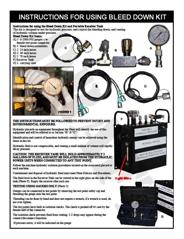
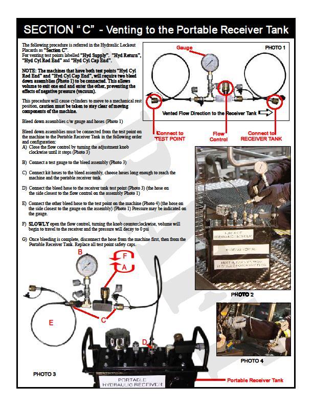
4 Hydraulic safety awareness training HSAC consultant to assist in writing a specific procedure for a specific one time event Example of best practice Bleed tools and equipment used which where designed for identifying and venting hydraulic fluid for controlling energy as part of a lockout procedure. This only represents an example and is specific to an application utilized in a particular facility on specific equipment. This section stands as examples of best practices and not be understood as part of the recommendations or procedures.
5
6

7 A This photo A, shows a counterbalance valve which is pad mounted directly to the hydraulic cylinder. This too has no means integrated to identify and safely vent the isolated fluid. Making modifications to integrate test/bleed points requires engineering and may also include recommendations and acceptance by the equipment manufacturer. There would be a shift in liability and warranty if not done by the manufacturer when done by a modifier/integrator. A catch 22 will exist if the integration is not made by the manufacturer at the point of manufacture. A post manufacture modification still puts the modifier/integrator at risk in order to make previsions for safety devices. If a modifier/integrator chooses to make post manufacture changes, the procedure would require very detailed instruction to reduce risk. Due to the exponential number of variables, one written safe work procedure will not effectively capture the highest risk reduction methods for each task or event. Although some tasks and events are similar they vary enough that risk can be lessened in some cases. A hazard assessment should be utilized to determine the controls for the lesser.
8 Conclusion; Primarily safety devices on mobile equipment are designed with the operator in mind also including public and environmental safety. Maintenance and repair personnel generally are working at greater risk due to equipment design. Maintaining and repairing equipment requires significant knowledge and skills to reduce risk. Risk becomes considerably higher when safety devices are not integrated into equipment to identify and control hazardous energy. Until standards and codes are developed and enforced, which increases safety for maintenance and repair personnel, many procedures will be deemed unsafe. In Canada in most provinces the under Occupational health and Safety Acts and Legislation; one can be charged for failure to provide a safe work environment and or procedure. Where an injury takes place from not controlling hazardous energy the province will lay heavy fines. On equipment manufactured where maintenance procedures are unsafe or there is no hierarchy of controls to mitigate a hazard and the procedure is deemed high risk, work should not be carried out. Buyers of equipment must consider this, as under most acts and regulations, the owner of the equipment can be included in litigation where a worker was injured. In Ontario all equipment purchased must undergo a prestart health and safety review, which is designed to determine the safety of the equipment and in most cases integration of safety devices and procedures prevail. The owner of the equipment in most cases an employer is fully responsible for the safety of personnel exposed to equipment therefore the equipment must be safe. Manufacturers in some countries are required to meet certain standards and codes which are designed to increase safety of equipment, however not all equipment meets safety standards that are recognized by Canada. This particular incident is not so isolated and until standards and codes are developed and enforced or intervention on the part of all stakeholders this matter of manufacturers design and integration to increase maintenance and repair safety will remain unresolved. Colin Bonner
Contents. Catalog HY /US Load and Motor Control Valves SERIES CAVITY DESCRIPTION FLOW PRESSURE PAGE NO. LPM/GPM BAR/PSI
 Load and Motor Control Contents SERIES CAVITY DESCRIPTION FLOW PRESSURE PAGE NO. LPM/GPM BAR/PSI STANDARD PILOT ASSISTED CB101... C10-3... Load Control Cartridge Valve...45/12... 380/5500... 5-6 MHC-010-S***
Unit 24: Applications of Pneumatics and Hydraulics
 Unit 24: Applications of Pneumatics and Hydraulics Unit code: J/601/1496 QCF level: 4 Credit value: 15 OUTCOME 2 TUTORIAL 9 ACCUMULATORS The material needed for outcome 2 is very extensive so there are
Lockout. HealthandSafetyOntario.ca. What is Lockout? How is a Lockout Done? Why is a Lockout Necessary?
 What is Lockout? Lockout means to physically neutralize all energies in a piece of equipment before beginning any maintenance or repair work. Lockouts generally involve: Stopping all energy flows (for
Lockout/Tagout - Energy Control Program
 Lockout/Tagout - Energy Control Program Lockout and Tagging of ELECTRICAL Circuits This portion of the K.R. Miller Contractors, Inc. safety program has been created to maintain a written copy of procedures
MARIPOSA COUNTY LOCKOUT/TAGOUT PROGRAM
 MARIPOSA COUNTY LOCKOUT/TAGOUT PROGRAM INTRODUCTION Mariposa County ( County ) facilities have equipment and systems that must be deenergized to allow for safe cleaning, repairing, servicing, setting-up,
General Lockout Training Briefing
 Page 1 of 5 Introduction What is Lockout? Lockout protects your personnel and plant from injury or accident by ensuring that equipment and machinery is properly isolated during scheduled maintenance, shutdown,
Hi-Force Limited Prospect Way Daventry Northants NN11 8PL United Kingdom Tel: +44(0) : Fax: +44(0) : Website:
 : Fax: +44(0) : Website:") 1.0 Inspection of the product upon receipt: On receipt of the product, visually inspect the item for any evidence of shipping damage. Please note shipping damage is not covered by warranty. If shipping
1.0 Inspection of the product upon receipt: On receipt of the product, visually inspect the item for any evidence of shipping damage. Please note shipping damage is not covered by warranty. If shipping
H. Control of Hazardous Energy: Lockout/Tag Out
 H. Control of Hazardous Energy: Lockout/Tag Out 1. Purpose Control of Hazardous energy is the purpose of the Lockout- Tagout Program. This program establishes the requirements for isolation of both kinetic
Lockout Tagout Program
 Lockout Tagout Program RIM of the World Unified School District 27315 North Bay Road Blue Jay, CA 92352 (909) 336-4100 July 2016 Safety and Risk Management Department RIM of the World Unified School District
DuPage County Environmental, Safety, Health & Property Loss Control Program Hazardous Energy Control (Lockout/Tagout)
") Purpose: To provide the minimum requirements for the lockout or tagout of energy isolating devices whenever work is performed or servicing is done on County of DuPage machinery, equipment, vehicles and
Purpose: To provide the minimum requirements for the lockout or tagout of energy isolating devices whenever work is performed or servicing is done on County of DuPage machinery, equipment, vehicles and
LOCK-OUT/TAG-OUT (LO/TO) SAFETY PROGRAM
 SAFETY PROGRAM") LOCK-OUT/TAG-OUT (LO/TO) SAFETY PROGRAM REGULATORY STANDARD: OSHA - 29 CFR 1910.147 BASIS: Approximately three million workers in the United States face risks from uncontrolled energy when servicing machinery
LOCK-OUT/TAG-OUT (LO/TO) SAFETY PROGRAM REGULATORY STANDARD: OSHA - 29 CFR 1910.147 BASIS: Approximately three million workers in the United States face risks from uncontrolled energy when servicing machinery
WESTERN CONNECTICUT STATE UNIVERSITY LOCKOUT/TAGOUT PROCEDURE S-107
 WESTERN CONNECTICUT STATE UNIVERSITY LOCKOUT/TAGOUT PROCEDURE S-107 Draft Issued 12/97 Revised 11/00 Please direct any questions or comments about the applicability of this document to Luigi Marcone, WCSU
Energy Control Procedures Lockout/Tagout 29 CFR
 Energy Control Procedures Lockout/Tagout 29 CFR 1910.147 Paul Schlumper, PE, CSP Georgia Tech Research Institute What is covered? Servicing and maintenance Normal production operations where: Employees
2523-LDG-E. Leader s Guide
 2523-LDG-E LOCKOUT/TAGOUT TRAINING FOR EMPLOYEES Leader s Guide 2008 ERI Safety Videos LOCKOUT/TAGOUT TRAINING FOR EMPLOYEES This easy-to-use Leader s Guide is provided to assist in conducting a successful
FLUID POWER FLUID POWER EQUIPMENT TUTORIAL ACCUMULATORS. This work covers part of outcome 2 of the Edexcel standard module:
 FLUID POWER FLUID POWER EQUIPMENT TUTORIAL ACCUMULATORS This work covers part of outcome 2 of the Edexcel standard module: UNIT 21746P APPLIED PNEUMATICS AND HYDRAULICS The material needed for outcome
What is pressure relief valve? Pressure relief valve
 What is pressure relief valve? Pressure relief valve What is: Relief valve Safety valve Safety relief valve Type of pressure relief valve Pressure relief valve sizing base What are the sizing basis of
Safe hydraulics for hydroforming presses. more finished product to be created from less raw material.
 profile Drive & Control Safe hydraulics for hydroforming presses Safety Standard Guidelines for Hydraulic Presses In several western regions, safety standards exist that describe how to achieve safe control
PAGE 1 OF 7 HEALTH, SAFETY & ENVIROMENTAL MANUAL PROCEDURE: S230 Lock-Out Tag-Out (LOTO) Program REV 4.0 8/13/2012
 Program REV 4.0 8/13/2012") PAGE 1 OF 7 LOCK-OUT TAG-OUT (LOTO) THE CONTROL OF HAZARDOUS ENERGY LOCKOUT/TAGOUT PROGRAM PURPOSE: 1. This standard establishes lockout/tagout (LOTO) procedures for the safety of personnel working on
PAGE 1 OF 7 LOCK-OUT TAG-OUT (LOTO) THE CONTROL OF HAZARDOUS ENERGY LOCKOUT/TAGOUT PROGRAM PURPOSE: 1. This standard establishes lockout/tagout (LOTO) procedures for the safety of personnel working on
Hazardous Energy Lockout Standard. Safety Resources
 Hazardous Energy Lockout Standard 2017 Contents 1 Purpose... 1 2 Applicable To... 1 3 Scope... 1 4 Definitions... 2 5 Legislation... 4 6 Hazardous Energy Lockout Program... 4 6.1 General Program Requirements...
Lockout / Tagout Safety Program
 Lockout / Tagout Safety Program Prepared by: The Ohio State University Environmental Health and Safety Occupational Safety & Industrial Hygiene 1314 Kinnear Road Columbus, OH 43212-1168 614-292-1284 Phone
Leak free Pipe Rupture Valve for Excavators
 Leak free Pipe Rupture Valve for xcavators Series motion and progress Reference: 3 P 9575 1/11.6 Classification: 43.325.355...325.35 1/17 Contents Page 1 General description................................................................
ACCUMULATOR OPERATING & MAINTENANCE INSTRUCTIONS
 ACCUMULATOR OPERATING & MAINTENANCE INSTRUCTIONS READ ALL INSTRUCTIONS PRIOR TO INSTALLATION AND OPERATION TO AVOID POSSIBLE INJURY Warning: Always consider any accumulator to contain pressure until proven
Lockout / Tag out Program
 Lockout / Tag out Program Presented by DOSHTI www.doshti.com You will learn Purpose of Lockout- Tag out Requirements for LOTO Types of Hazardous Energy Procedures for LOTO The OSHA Standard for the Control
LOCKOUT/TAGOUT PROGRAM
 LOCKOUT/TAGOUT PROGRAM HOW CLIMATE ENGINEERS INC. COMPLIES WITH THELO/TO STANDARD It is the intent of Climate Engineers Inc. to comply with OSHA s Control of Hazardous Energy Standard (1910.147). The following
Energy Control. Suite 2A, 55 Frid Street Hamilton, ON L8P 4M3 office: cell:
 Energy Control Suite 2A, 55 Frid Street Hamilton, ON L8P 4M3 office: 905.577.0303 cell: 905.977.0210 consultant@staffaid.ca www.staffaid.com Safety, Energy Control, Power Lockout & Function Test Procedures
DUQUESNE UNIVERSITY LOCKOUT/TAGOUT PROGRAM
 DUQUESNE UNIVERSITY LOCKOUT/TAGOUT PROGRAM Prepared by: Environmental Health and Safety Department TABLE OF CONTENTS Page Purpose 1 Scope 1 Introduction 2 Regulatory Requirements 2 Protective Materials
Instruction sheet for Hydraulic Cylinder
 Oper at or smanual 1088710891 Hydr aul i ccyl i nder s Instruction sheet for Hydraulic Cylinder NOTE PLEASE READ AND FOLLOW THIS INSTRUCTION BEFORE YOU USE Yellow Jackit CYLINDERS. Carefully inspect all
Health & Safety Policy and Procedures Manual SECTION 6 ELECTRICAL SAFETY / CONTROL OF HAZARDOUS ENERGY
 SECTION 6 ELECTRICAL SAFETY / CONTROL OF HAZARDOUS ENERGY 1. CONTROL OF HAZARDOUS ENERGY POLICY AND PROCEDURES A. OSHA References: 29 CFR 1910.147, 29 CFR 1910.332, 29 CFR 1910.333, 29 CFR 1926.417 B.
Lockout/Energy Control
 Lockout/Energy Control Presented By: Sotaris, LLP 2000 Auburn Drive, Suite 200 Beachwood, Ohio 44122 P: 216-378-7650 F: 866-794-5756 W: www.sotaris.com E: awj@sotaris.com 1 About Me Andrew W. Johnson,
Safety Beyond the Electrics
 Safety Beyond the Electrics Tom Eastwood Machine Safeguarding and Robotics Advisor Workplace Safety and Prevention Services Jim Van Kessel Electrical Engineer JVK Industrial Automation Inc. NOTE: This
DESIGN DATA A WET PIPE BLADDER TANK FOAM/WATER SYSTEM WITH HYDRAULICALLY ACTUATED DELUGE CONCENTRATE CONTROL VALVE
 February 9, 1998 Foam 101a A BLADDER TANK WITH 1. DESCRIPTION A Wet Pipe Bladder Tank Foam/Water System is a standard wet pipe automatic sprinkler system capable of discharging a foam/water solution automatically
PRESCOTT SCHOOL DISTRICT NO South A Street Prescott, WA The Control of Hazardous Energy (Lockout/Tagout)
") PRESCOTT SCHOOL DISTRICT NO. 402-37 207 South A Street Prescott, WA 99348 509-849-2217 The Control of Hazardous Energy (Lockout/Tagout) I. Purpose The Control of Hazardous Energy (Lockout/Tagout) This
PRESCOTT SCHOOL DISTRICT NO. 402-37 207 South A Street Prescott, WA 99348 509-849-2217 The Control of Hazardous Energy (Lockout/Tagout) I. Purpose The Control of Hazardous Energy (Lockout/Tagout) This
Dri-Line Mk3 Monnier Compressed Air Drain Trap
 5044050/2 IM-P504-24 CH Issue 2 Dri-Line Mk3 Monnier Compressed Air Drain Trap Installation and Maintenance Instructions 1. Safety information 2. General product information 3. Installation and Operation
KBV21i and KBV40i Key Operated Boiler Blowdown Valves Installation and Maintenance Instructions
 4059051/3 IM-P405-48 EMM Issue 3 KBV21i and KBV40i Key Operated Boiler Blowdown Valves Installation and Maintenance Instructions 1. Safety information 2. General product information 3. Installation 4.
ANNUAL IDOL COMPLIANCE TRAINING
 ANNUAL IDOL COMPLIANCE TRAINING Lock Out / Tag Out Refresher SUGAR GROVE FIRE DEPARTMENT 1 TRAINING DIVISION Instructions To complete this independent study program, view the entire program, advancing
Lockout - Tagout. Control of Hazardous Energy OSHA Standard
 Lockout/Tagout Lockout - Tagout Control of Hazardous Energy OSHA Standard 1910.147 What Is Lockout/Tagout? Referred to as LOTO Blocks the flow of energy from power source to the equipment Provides means
LOCKOUT-TAGOUT PROGRAM
 LOCKOUT-TAGOUT PROGRAM Please Note: This material, or any other material used to inform employers/employees of compliance requirements of OSHA standards through simplification of the regulations should
WARNING: READ THE GENERAL INFORMATION MANUAL INCLUDED FOR OPERATING AND SAFETY PRECAUTIONS AND OTHER IMPORTANT INFORMATION.
 GSR500 Ram Assembly General Description The GSR500 single post lift / ram uses a 3-1/4 air powered cylinder, which is welded to a heavy gauge base. It is normally used to raise and lower a fluid handling
Copyright, 2005 GPM Hydraulic Consulting, Inc.
 Troubleshooting and Preventive Maintenance of Hydraulic Systems Learning to Read the Signs of Future System Failures Instructed by: Al Smiley & Alan Dellinger Copyright, 2005 GPM Hydraulic Consulting,
DF1 and DF2 Diffusers
 1550650/4 IM-P155-07 ST Issue 4 and Diffusers Installation and Maintenance Instructions 1. Safety information 2. General product information 3. Installation 4. Commissioning 5. Operation 6. Maintenance
TECHNICAL DATA. than the water inlet pressure to the concentrate
 Foam102a 1. DESCRIPTION The Viking Low Flow Foam/Water proportioning system, is a UL Listed and FM Approved system, for use with 3M foam concentrates. This system consists of a standard wet pipe sprinkler
PV4 and PV6 Piston Valves
 1181250/1 IM-P118-05 ST Issue 1 PV4 and PV6 Piston Valves Installation and Maintenance Instructions 1. Safety information 2. General product information 3. Installation 4. Commissioning 5. Operation 6.
Lockout/Tagout Safety Policy
 University of North Carolina Wilmington Environmental Health & Safety Workplace Safety Lockout/Tagout Safety Policy GENERAL The UNCW Environmental Health & Safety Department (EH&S) is authorized by UNCW
Big 5 Site Training Support Information
 Big 5 Site Training Support Information Line Break July & August 2008 Safety Standard Philosophy Our Safety Standards are in place to address Occupational Safety Hazards they do not address the Process
Interface Devices, Inc. Hydraulic Mini Mule
 Interface Devices, Inc. Hydraulic Mini Mule INSTALLATION, OPERATION & MAINTENANCE MANUAL IMPORTANT! FILE THIS MANUAL IN A SAFE PLACE FOR FUTURE SERVICE & PARTS NEEDS ALWAYS REFERENCE THE SERIAL NUMBER
LO/TO LOCKOUT/TAGOUT PROGRAM
 LO/TO LOCKOUT/TAGOUT PROGRAM April 2017 CONTENTS Section 1: Introduction...1 Section 2: Purpose... 1 Section 3: Application... 1 Section 4: Definitions... 2 Section 5: Roles and Responsibilities... 4 Section
ACCU-PULSE Installation and Operation Instructions
 ACCU-PULSE Installation and Operation Instructions Pump Discharge Installation: Chargeable Models Step 1: Mounting Position Mount ACCU-PULSE as close to the pump discharge as possible to absorb the pulse
TABLE OF CONTENTS PART 2 - CONFINED SPACES
 May 11, 2006 TABLE OF CONTENTS PART 2 - CONFINED SPACES Page DEFINITIONS... 2-1 GENERAL... 2-2 RESPONSIBILITIES... 2-2 HAZARD ASSESSMENT AND WORK PROCEDURES... 2-3 IDENTIFICATION AND ENTRY PERMITS... 2-3
Emergency Water Injection /28/2017 updated 07/21/2017
 Emergency Water Injection 101 06/28/2017 updated 07/21/2017 Written By: Ronald D. Huffman, www.respondertraining.com When something happens and you're faced with an uncontrollable liquid propane leak you
Introduction. Part one: Identify the Hydraulic Trainer Components
 The University Of Jordan School of Engineering Mechatronics Engineering Department Fluid Power Engineering Lab Experiments No.4 Introduction to Hydraulic Trainer Objective: Students will be able to identify
Lockout Tagout Policy
 Office of Environmental Health & Safety www.moreheadstate.edu/ehs 606-783-2584 Lockout Tagout Policy PURPOSE To establish procedures for the de-energization and isolation of energy sources or the lockout
POTENTIAL HEALTH & SAFETY HAZARDS
 Number: OH&S 18.09.1 Revision Date: 2011.06 Confined Space 1. PURPOSE 2. SCOPE 1.1. To properly designate Confined Spaces (CS) at Thompson Rivers University (TRU), to provide guidance to ensure the safety
SAFETY DIRECTIVE 2.0 DEPARTMENTS AFFECTED. This Administrative Directive shall apply to all Town of Marana departments and employees.
 SAFETY DIRECTIVE Title: Control of Hazardous Energy Lock-out/Tag-out/Try-out Issuing Department: Town Manager s Safety Office Effective Date: July 1, 2014 Approved: Gilbert Davidson, Town Manager Type
TESCOM 50-4X Series Safety, Installation & Start-Up Procedures
 Operations & Service Manual TESCOM 50-4X Series Safety, Installation & Start-Up Procedures Do not attempt to select, install, use or maintain this product until you have read and fully understood this
Gettysburg College. Energy Control Program
 Gettysburg College Energy Control Program Adopted October 2009 Reviewed and Updated February 2015 Reviewed and Updated July 2015 I. Energy Control Procedures Table of Contents A. General Lockout Procedures
KBV21i and KBV40i Air Actuated Boiler Blowdown Valves
 4059051/1 IM-P405-48 AB Issue 1 KBV21i and KBV40i Air Actuated Boiler Blowdown Valves Installation and Maintenance Instructions 1. Safety information 2. General product information 3. Installation 4. Commissioning
PART Q CONTROL OF HAZARDOUS ENERGY (LOCKOUT-TAGOUT)
") PART Q CONTROL OF HAZARDOUS ENERGY (LOCKOUT-TAGOUT) WAC Page 296-307-320 Control of hazardous energy (lockout-tagout). 1 296-307-32001 What does this section cover? 1 296-307-32003 When does this section
PART Q CONTROL OF HAZARDOUS ENERGY (LOCKOUT-TAGOUT) WAC Page 296-307-320 Control of hazardous energy (lockout-tagout). 1 296-307-32001 What does this section cover? 1 296-307-32003 When does this section
Engineered solutions for complex pressure situations
 SPECIAL SERVICES Engineered solutions for complex pressure situations Cudd Energy Services (CES) delivers custom engineered solutions to resolve complex pressure situations resulting from equipment failure
AIR COMPRESSOR MANUAL INSTALLATION, OPERATION AND MAINTENANCE GUIDE
 AIR COMPRESSOR MANUAL INSTALLATION, OPERATION AND MAINTENANCE GUIDE 1. DESCRIPTION The compressor is a reciprocating air pump mounted on and driven by an electric induction motor. Mounted on a sturdy frame
Spirax Compact FREME Flash Recovery Energy Management Equipment
 IM-UK-cFREME UK Issue 1 Spirax Compact FREME Flash Recovery Energy Management Equipment Installation and Maintenance Instructions 1. Safety information 2. General product information 3. Installation 4.
SAMPLE WRITTEN PROGRAM for Control of Hazardous Energy LOCKOUT TAGOUT
 SAMPLE WRITTEN PROGRAM for Control of Hazardous Energy LOCKOUT TAGOUT SAMPLE WRITTEN PROGRAM The objective of this procedure is to establish a means of positive control to prevent the accidental starting
Repair Alert Never use compressed air to dismantle a hydraulic cylinder
 Repair Alert Never use compressed air to dismantle a hydraulic cylinder Topic: A hydraulic cylinder with integral pilot-operated check valve can present a considerable safety hazard for an unsuspecting
Float Operated Level Controllers
 CONTENTS Float Operated Level Controllers IM0015 Nov. 2014 PAGE Introduction 1 Scope 1 Description 1 Specification 1 Control Installation 2 INTRODUCTION Side Mount Back Mount Prior to installing, the instructions
ARKANSAS TECH UNIVERSITY FACILITIES MANAGEMENT HEALTH AND SAFETY MANUAL (LOCKOUT/TAGOUT) 30.0
 30.0") () 30.0 The purpose of the Energy Control Policy (Lockout/Tagout) is to ensure that before any employee performs any servicing and/or maintenance on machinery or equipment, where the unexpected energizing,
() 30.0 The purpose of the Energy Control Policy (Lockout/Tagout) is to ensure that before any employee performs any servicing and/or maintenance on machinery or equipment, where the unexpected energizing,
Installation and Service Manual
 An Actuant Company Installation and Service Manual Heavy Duty Hydraulic Stabilization Legs CONTENTS Part # 3010003129 REV 0D Section Page 1.0 Receiving Instructions 2 2.0 Safety Issues 2 3.0 Hydraulic
Manual Actuated Boiler Blowdown Valves
 Manual Actuated Boiler Blowdown Valves Installation and Maintenance Instructions 1. Safety information 2. General product information 3. Installation 4. Operation 5. Maintenance 6. Spare parts p.1 1. Safety
CONTROL OF HAZARDOUS ENERGY (LOCKOUT/TAGOUT) PROGRAM
 PROGRAM") Page: 1 of 15 1.0 Purpose and Applicability 2.0 Scope 1.1 It is the policy of the University of Pennsylvania in coordination with the Office of Environmental Health and Radiation Safety to provide the
Page: 1 of 15 1.0 Purpose and Applicability 2.0 Scope 1.1 It is the policy of the University of Pennsylvania in coordination with the Office of Environmental Health and Radiation Safety to provide the
TECHNICAL DATA. Low-Flow Foam Preaction System with Hydraulically Actuated Concentrate Control Valve.
 Foam 302 a 1. DESCRIPTION (Refer to Figure 1 on page 302 e.) The Viking Low-Flow Foam/Water Proportioning System is a UL Listed and FM Approved system, for use with 3M and Viking brand foam concentrate.
230-LOCKOUT/TAGOUT PROGRAM
 230.1 PURPOSE A. To confirm implementation, operation, and recordkeeping of Central New Mexico Community College(CNM) lockout/tagout program in compliance with 29 CFR 1910.147. 230.2 SCOPE A. The requirements
Isolating plant. Guidance Note. June 2011
 Guidance Note Isolating plant This Guidance Note provides general advice to employers about safely working on plant without energy sources. June 2011 Background Failure to shut down, de-energise or isolate
AUTOMATED INDUSTRIAL MACHINE, INC TOGGLE-AIRE
 AUTOMATED INDUSTRIAL MACHINE, INC TOGGLE-AIRE DIVISION Installation, Operation and Maintenance Hydro-Pneumatic Series Bench Presses IMPORTANT It is the responsibility of the employer/purchaser to provide
Isolation Lockout and Tagging
 PURPOSE To define the minimum system requirements for isolation of plant and equipment from hazardous substances, mechanical, electrical or other energy sources to protect all workers from personal injury
Load Controls Screw In Cartridge Valves Pressures to 350 bar (5000 psi) Flows to 190 l/min (50 USgpm)
 Flows to 190 l/min (50 USgpm)") Vickers Cartridge Valves Load Controls Screw In Cartridge Valves Pressures to 50 bar (5000 psi) Flows to 90 l/min (50 USgpm) Rev. 2/99 722 Contents MODEL DESCRIPTION TYP. APPLICATION PRESSURE bar (psi)
Vickers Cartridge Valves Load Controls Screw In Cartridge Valves Pressures to 50 bar (5000 psi) Flows to 90 l/min (50 USgpm) Rev. 2/99 722 Contents MODEL DESCRIPTION TYP. APPLICATION PRESSURE bar (psi)
HPB25 Hydraulic Paving Breaker
 INSTRUCTION MANUAL HPB25 Hydraulic Paving Breaker Read and understand all of the instructions and safety information in this manual before operating or servicing this tool. Register this product at www.greenlee.com
Instruction Sheet 1.0 IMPORTANT RECEIVING INSTRUCTIONS 2.0 SAFETY. 2.1 Introduction. 2.2 Hydraulic Cylinder Safety Precautions (RT-Series)
") Instruction Sheet POWERFUL SOLUTIONS. GLOBAL FORCE. L4211 Rev. A 09/17 RT-Series Multi-Stage Telescopic Hydraulic Cylinders Table of Contents Page 1.0 IMPORTANT RECEIVING INSTRUCTIONS... 1 2.0 SAFETY...
Instruction Sheet POWERFUL SOLUTIONS. GLOBAL FORCE. L4211 Rev. A 09/17 RT-Series Multi-Stage Telescopic Hydraulic Cylinders Table of Contents Page 1.0 IMPORTANT RECEIVING INSTRUCTIONS... 1 2.0 SAFETY...
TOP VALVE. Pat. #5,857,486 & 5,944,050. Mid-Range Pressure PSIG Back Pressure and Pressure Relief Valves. Instruction Manual
 TOP VALVE Pat. #5,857,486 & 5,944,050 Mid-Range Pressure 50 232 PSIG Back Pressure and Pressure Relief Valves Instruction Manual Please Note: This instruction manual provides detailed information and instructions
S1, S2, S3, S5, S6, S7, S8, S12 and S13 Separators Installation and Maintenance Instructions
 PREVIOUS REFERENCE NO. IMP02355 0231150/13 IMF0501ENISS2 CMGT S1, S2, S3, S5, S6, S7, S8, S12 and S13 Separators Installation and Maintenance Instructions 1. Safety information 2. General product information
University of Arkansas Office of Environmental Health and Safety
 University of Arkansas Office of Environmental Health and Safety Procedure Name: Lockout / Tagout Procedure Number: 600.26 Effective Date: 12-1-2015 Procedure: Developed in accordance with the OSHA Control
DCV10 Stainless Steel Disc Check Valve for use with Condensate Pumps
 6018050/1 IM-P601-33 ST Issue 1 DCV10 Stainless Steel Disc Check Valve for use with Condensate Pumps Installation and Maintenance Instructions 1. Safety information 2. General product information 3. Installation
Subsea Safety Systems
 Subsea Safety Systems The ELSA-HP has been developed to service the high pressure horizontal tree completion and intervention market. With systems designed and qualified up to 15,000 psi, 250 degf and
Service Call: Vacuum Prevention System Testing on Category A and B Aerial Devices. Tools Required: 1. Atmospheric Vent Test Set (P/N )
") Service Call: Vacuum Prevention System Testing on Category A and B Aerial Devices Tools Required: 1. Atmospheric Vent Test Set (P/N 488180) *An automotive vacuum test kit with various fittings to hook
Service Call: Vacuum Prevention System Testing on Category A and B Aerial Devices Tools Required: 1. Atmospheric Vent Test Set (P/N 488180) *An automotive vacuum test kit with various fittings to hook
EASTERN ENERGY SERVICES PTE LTD. 60 Kaki Bukit Place #02-19 Eunos Tech Park Singapore, SG Singapore Telephone: Fax:
 2 Table Of Contents 1. Introduction 3 2. About this Manual 3 3. Contacting YZ Systems 3 4. Vessel Components 4 5. Specifications 5 6. Application 6 7. Theory of Operation 7 8. DuraSite Installation & Use
PROGRAM: Control of Hazardous Energy (LOCKOUT) Chapter 5
 Chapter 5") Classroom, Occupational Safety & Health Plan Date: August 5, 2017 PROGRAM: Control of Hazardous Energy (LOCKOUT) Chapter 5 1. Purpose This document establishes the Lockout Program for Tidewater Community
Classroom, Occupational Safety & Health Plan Date: August 5, 2017 PROGRAM: Control of Hazardous Energy (LOCKOUT) Chapter 5 1. Purpose This document establishes the Lockout Program for Tidewater Community
Product Information Report Lockout/Tagout Hazardous Energy Control
 Overview A properly implemented (LOTO) program is designed to protect workers involved in the maintenance and servicing of equipment from the dangerous effects of hazardous energy caused by the unexpected
Lock Out/Tag Out Control of Hazardous Energy
 Lock Out/Tag Out Control of Hazardous Energy University Facilities Internal Procedure: July 1, 2013 Effective date: July 1, 2013 Last Modified: April 2013 Approved by: Bob Wells 1.0 Program Objective UF
Lecture 19 PRESSURE-CONTROL VALVES [CONTINUED]
![Lecture 19 PRESSURE-CONTROL VALVES [CONTINUED]](/thumbs/76/73283391.jpg "Lecture 19 PRESSURE-CONTROL VALVES [CONTINUED]") Lecture 19 PRESSURE-CONTROL VLVES [CONTINUED] 1.5 Counterbalance Valve Schematic diagram of counterbalance valve is shown in Fig. 1.14. These normally closed valves are primarily used to maintain a back
Lecture 19 PRESSURE-CONTROL VLVES [CONTINUED] 1.5 Counterbalance Valve Schematic diagram of counterbalance valve is shown in Fig. 1.14. These normally closed valves are primarily used to maintain a back
LOCK OUT \ TAG OUT PROGRAM
 LOCK OUT \ TAG OUT PROGRAM University of Portland 5000 N. Willamette Blvd Portland, OR 97203-5798 January 2005 Revision 2.5 Prepared By: Environmental Health and Safety i TABLE OF CONTENTS Content SECTION
then the work done is, if the force and the displacement are in opposite directions, then the work done is.
 1. What is the formula for work? W= x 2. What are the 8 forms of energy? 3. Write the formula for the following: Kinetic Energy Potential Energy 4. If the force and the displacement are in the same direction,
LOCKOUT/TAGOUT PROGRAM
 Santa Clarita Community College District LOCKOUT/TAGOUT PROGRAM Revised March 2018 TABLE OF CONTENTS PURPOSE... 3 COMPLIANCE...4 DEFINITIONS...5 SECTION I - ENERGY CONTROL PROCEDURES... 7 SECTION II -
OBSOLETE. Wet pipe low flow manifold system
 June 1, 2008 Foam 15a 1. Description Multiple risers can be supplied from a single proportioning device. A riser manifold is installed with various riser types and sizes that are to supply foam solution
Air Operated Hydraulic Pumping Systems to 50,000 psi
 High Pressure Equipment Air Operated Hydraulic Pumping Systems to 50,000 psi PS-10: 10,000 psi PS-20: 20,000 psi PS-30: 30,000 psi PS-40: 40,000 psi PS-50: 50,000 psi PS-90: 90,000 psi High Pressure air
DESIGN DATA OBSOLETE. C. Inspections - It is imperative that the system be inspected and tested on a regular basis. See Inspection
 February 9, 1998 Foam 201a 1. DESCRIPTION A Deluge Bladder Tank Foam/Water System is a standard deluge system capable of discharging a foam/water solution automatically through open sprinklers, spray nozzles,
ANNEX AMENDMENTS TO THE INTERNATIONAL CODE FOR FIRE SAFETY SYSTEMS (FSS CODE) CHAPTER 15 INERT GAS SYSTEMS
 CHAPTER 15 INERT GAS SYSTEMS") Annex 3, page 2 ANNEX AMENDMENTS TO THE INTERNATIONAL CODE FOR FIRE SAFETY SYSTEMS (FSS CODE) CHAPTER 15 INERT GAS SYSTEMS The text of existing chapter 15 is replaced by the following: "1 Application This
Annex 3, page 2 ANNEX AMENDMENTS TO THE INTERNATIONAL CODE FOR FIRE SAFETY SYSTEMS (FSS CODE) CHAPTER 15 INERT GAS SYSTEMS The text of existing chapter 15 is replaced by the following: "1 Application This
Lockout/Tagout Program
 Lockout/Tagout Program Prepared by: Occupational Health and Safety Reviewed by: Joint Health and Safety Committees Approved by: Chief Human Resources Officer November 2014 TABLE OF CONTENTS 1.0 Purpose...3
Safety Manual: Hazardous Energy. January, 2017
 Safety Manual: Hazardous Energy January, 2017 9.0 Hazardous Energy Introduction Energized equipment in the workplace pose a significant risk of injury and death. If the unexpected energization or start-up
Hazardous Energy Control (Lockout-Tagout)
") Hazardous Energy Control (Lockout-Tagout) The purpose of this program is to prevent inadvertent operation or energization of machines, equipment, or processes in order to protect employees and establish
Hazardous Energy Control (Lockout-Tagout) The purpose of this program is to prevent inadvertent operation or energization of machines, equipment, or processes in order to protect employees and establish
TA10A and TA10P Steam Tracing Temperature Control Valves Installation and Maintenance Instructions
 3500032/2 IM-P350-02 CH Issue 2 TA10A and TA10P Steam Tracing Temperature Control Valves Installation and Maintenance Instructions 1. Safety information 2. General product information 3. Installation 4.
RiskTopics. Lockout/Tagout October 2017
 RiskTopics Lockout/Tagout October 2017 This Risktopic is designed to outline guidelines for lockout/tagout and provide assistance in developing a management program to reduce the risk of injury from unintended
Control of Hazardous Energy Program (Lockout/Tagout)
") Control of Hazardous Energy Program (Lockout/Tagout) 1 The Control of Hazardous Energy (Lockout/Tagout) Program 1910.147 The following lockout/tagout program is provided to assist employees in complying
Control of Hazardous Energy Program (Lockout/Tagout) 1 The Control of Hazardous Energy (Lockout/Tagout) Program 1910.147 The following lockout/tagout program is provided to assist employees in complying
TITAN FLOW CONTROL, INC.
 PREFACE: This manual contains information concerning the installation, operation, and maintenance of Titan Flow Control (Titan FCI) Simplex Basket Strainers. To ensure efficient and safe operation of Titan