Flowline, Inc Humbolt Street Los Alamitos, CA Tel: (562) Fax: (562) Rev B MN of 16
|
|
|
- Noah Shelton
- 5 years ago
- Views:
Transcription
 598 3015 Fax: (562) 431 8507 www.flowline.")
1 DeltaSpan Intrinsically Safe Clean Water & Oil Pressure or Pump Lift Station Pressure Level Transmitter LD31 S3_1, LD31 S4_1, LD32 S3_1 & LD32 S4_1 Series Manual LD31 series LD32 Series Flowline, Inc Humbolt Street Los Alamitos, CA Tel: (562) Fax: (562) Rev B MN of 16
2 INTRODUCTION / TABLE OF CONTENTS Step One The DeltaSpan LD31 Series Intrinsically Safe Clean Water & Oil or LD32 Series Intrinsically Safe Pump Lift Station Pressure Level Transmitters are manufactured for years of trouble free service in the harshest applications. The pressure transmitter measures the height of liquid above the position in the tank referenced to atmospheric pressure. The transmitter consists of a piezoresistive sensing element, encased in 316 SS housing. The LD31 series features a bullet nose design protects the diaphragm from damage. Superior lightning and surge protection utilizing dual arrestor technology, grounded to case, eliminating both power supply surges and lightning ground strike transients. Large diameter 316 SS diaphragm seal is nonclogging and damage resistant to floating solids. The transmitter is equipped with a 270 pound tensile strength shielded and vented cable. Ventilation tube in the cable automatically compensates for changes in atmospheric pressure above the tank. The vent is protected with a maintenance free filter eliminating particulate or water droplets from entering the transducer. For extra protection against high humidity environments, Flowline offers the LD desiccant filter that can be attached to the vent tube. Excellent chemical compatibility with 316 construction Lightning and surge protection on all models Maintenance free vent filter LD31 series features slim design for tight applications LD32 series features large diameter, non clogging, damage resistant, 316 SS diaphragm seal Table of Contents Specification:... 3 Control Drawing:... 4 Dimensions... 5 Safety Precautions:... 6 Components:... 7 Getting Started... 8 How to convert Pressure into Liquid Height?... 8 How to select the correct pressure transmitter?... 8 How does Specific Gravity affect pressure transmitters?... 9 How to configure a panel meter when a pressure transmitter is used? Electrical Installation Wire Length Wiring Control Drawing Wiring Installation Interference Termination Maintenance Testing the transmitter Warranty of 16 MN Rev B
 Compensated 0 to 176 F ( 18 to 80 C) Temperature Range: Thermal Effect: Less than ±0.")
 21/ 31: 60 (18.")
3 SPECIFICATIONS Service: Compatible liquids Wetted Materials: Body: 316 SS, 316L SS and Buna N Cable: Polyurethane or ETFE Bullet Nose: PVC (LD31 series only) Accuracy: ±0.25% of full scale Temperature Limit: 0 to 176 F ( 18 to 80 C) Compensated 0 to 176 F ( 18 to 80 C) Temperature Range: Thermal Effect: Less than ±0.02%/ F Pressure Limit: 2X full scale Power Requirement: 10 to 28 VDC Output Signal: 4 to 20 ma DC, 2 wire Response Time: 50 ms Max. Loop Resistance: 900 ohms Electrical Connections: Wire pigtail Cable Length: 01/ 11: 40 (12.2 m) 21/ 31: 60 (18.3 m) Mounting Orientation: Suspended in tank below level being measured Can be placed on the bottom of the tank on its side Weight: 2.2 lb (1.0 kg) (LD31 series) 4.3 lb (2.0 kg) (LD32 series) Agency Approvals: CE, UL Intrinsically Safe to UL Standard 913. (See Intrinsic Safety Approval Classification.) Step Two The following standards were used for CE approval: IEC : 2001 IEC : 2006 IEC : 2004 IEC : 2005 IEC : 2006 IEC : 2001 CENELEC EN 55011: 2003 CENELEC EN 61326: /336/EEC EMC Directive WARNING: To prevent ignition of flammable or combustible atmospheres, disconnect power before servicing. Use with approved safety barriers using entity evaluation. Series LD31 LD32 Vmax 26 VDC 28 VDC Imax 93 ma 93 ma Ci 0.051uF uf Li 240 uh 240 uh Pi W W WARNING: Do not exceed specified supply voltage ratings. Permanent damage not covered by warranty will result. This device is not designed for 120 or 240 volt AC operations. Use only on 10 to 28 VDC. Optional Desiccant Filter (LD ): o For extra protection against humidity we offer the LD desiccant filter that can be attached to the vent tube. Optional Cable Hanger (LD90 S000): o Attach the cable hanger to the ½ thread of the LD31 or LD32 series and connect to the loop a chain to provide a secure method for lowering and raising the sensor. o The cable hanger is ideal for sumps or wet wells. Rev B MN of 16
4 CONTROL DRAWING Step Three 4 of 16 MN Rev B


5 DIMENSIONS Step Four Technology A sealed pressure transmitter is placed near or on the bottom of the tank. A stainless steel pressure diaphragm within the pressure transmitter is exposed on one side to the application liquid. The other side is exposed to the reference pressure via a small ventilation tube located inside of the Polyurethane cable. A difference in pressure between liquid and reference pressures will slightly deflect the diaphragm. The deflection of the diaphragm is measured by a built in microprocessor that provides greater linearity correction over common thermal compensation methods. A 4 20 ma current signal proportional the height of the liquid is generated from the microprocessor. LD31 Series: LD32 Series: Material Compatibility: o The LD31 / LD32 series is made of 316 Stainless Steel (316 SS), 316L Stainless Steel (316L SS) with a cable of Polyurethane or Ethylene Tetrafluoroethylene (ETFE). The LD31 series has a bullet nose of Polyvinyl Chloride (PVC). o Make sure that the switch is compatible with the application liquids. To determine the chemical compatibility between the sensor and its application liquids, refer to the Compass Corrosion Guide, available from Compass Publications ( ). Rev B MN of 16
6 SAFETY PRECAUTIONS Step Five About this Manual: PLEASE READ THE ENTIRE MANUAL PRIOR TO INSTALLING OR USING THIS PRODUCT. This manual includes information on all versions of the DeltaSpan Series Pressure Level Transmitter from Flowline; models LD31 S3, LD31 S4, LD32 S3 and LD32 S4. Please refer to the part number located on the transmitter label to verify the exact model which you have purchased. User s Responsibility for Safety: Flowline manufactures a wide range of liquid level sensors and technologies. While each of these technologies are designed to operate in a wide variety of applications, it is the user s responsibility to select a technology that is appropriate for the application, install it properly, perform tests of the installed system, and maintain all components. The failure to do so could result in property damage or serious injury. Proper Installation and Handling: Only properly trained staff should install and/or repair this product. Use a proper sealant with all installations. Always check for leaks prior to system start up. Wiring and Electrical: CAUTION: Do not exceed specified supply voltage rating of 28 VDC. Permanent damage not covered by warranty will result. This device is not designed for 120 or 240 volt AC operation. Use only on 10 to 28 VDC. Temperature and Pressure: The LD31 and LD32 series are designed for use in application temperatures from 18 to 80 C (0 to 176 F). Both series are designed for use at pressures up to 2 x the full span. Material Compatibility: Both series are made of 316 Stainless Steel (316 SS), 316L Stainless Steel (316L SS) with a cable of Polyurethane or Ethylene Tetrafluoroethylene (ETFE). The LD31 series has a bullet nose of Polyvinyl Chloride (PVC). Make sure that the model which you have selected is chemically compatible with the application liquids. Flammable, Explosive and Hazardous Applications: The LD31/LD32 series is UL listed for use in Hazardous (Classified) Locations. The protection method is by Intrinsic Safety, ia. It was investigated by UL under UL Standard 913 Sixth Edition and CSA Standard No For use in Hazardous (Classified) Locations: Class I Div. 1 Groups A,B,C,D; Class II Div. 1 Groups E,F,G; Class III Div. 1; Temperature Code: 80 C ambient; Install in accordance with control drawing M Make a Fail Safe System: Design a fail safe system that accommodates the possibility of transmitter failure or battery power loss. In critical applications, Flowline recommends the use of redundant backup systems and alarms in addition to the primary system. 6 of 16 MN Rev B

7 COMPONENTS Step Six DeltaSpan is offered in sixteen different models, based upon pressure rating and cable material. Depending on the model purchased, you may or may not have been shipped all the components shown below. DeltaSpan Intrinsically Safe Clean Water & Oil Pressure Level Transmitters (LD31 Series) Part Number Maximum Pressure Range in Water Column Cable Length Cable Material LD31 S psi ft wc (3.52 m wc) LD31 S psi ft wc (7.04 m wc) 40 (12.2 m) LD31 S psi ft wc (10.56 m wc) LD31 S psi ft wc (14.08 m wc) 60 (18.3 m) Polyurethane LD31 S401 LD31 S411 LD31 S421 LD31 S psi 10 psi 15 psi 20 psi ft wc (3.52 m wc) ft wc (7.04 m wc) ft wc (10.56 m wc) ft wc (14.08 m wc) 40 (12.2 m) 60 (18.3 m) DeltaSpan Intrinsically Safe Pump Lift Station Pressure Level Transmitters (LD32 Series) Part Number Maximum Pressure Range in Water Column Cable Length Cable Material LD32 S psi ft wc (3.52 m wc) LD32 S psi ft wc (7.04 m wc) 40 (12.2 m) LD32 S psi ft wc (10.56 m wc) LD32 S psi ft wc (14.08 m wc) 60 (18.3 m) Polyurethane LD32 S401 LD32 S411 LD32 S421 LD32 S psi 10 psi 15 psi 20 psi ft wc (3.52 m wc) ft wc (7.04 m wc) ft wc (10.56 m wc) ft wc (14.08 m wc) 40 (12.2 m) 60 (18.3 m) Quick Start Guide Vent Filter o Located on the end of the Vent Tube o If the application requires the vent tube to be cut to length, then remove the vent filter and place on the end of the new end of the vent tube. ETFE ETFE Desiccant Filter (Optional) o For extra protection against humidity we offer the LD desiccant filter that can be attached to the vent tube. Rev B MN of 16


: 15 psi x 2.31 /psi = 34.65 or 15 psi x 0.704 m/psi = 10.")
8 GETTING STARTED Step Seven Pressure transmitters are designed to be submersed within the application fluid. The transmitters can either rest along the bottom of the tank or be suspended at any desired level within the tank. Please note that the physical location of the level transmitter will indicate the lowest level of measurement within the tank. For example: mounting the transmitter 1 foot from the bottom of the tank, then the lowest reading of liquid will be 1 foot from the bottom. How to convert Pressure into Liquid Height? Pressure transmitters are all describe by the pressure range and not by Liquid Height. To convert pressure to Liquid Height, use the following ratio: 1 psi = 2.31 feet of water or 1 psi = meters of water Therefore, a 15 psi transmitter will have a Liquid Height = feet (10.56 m): 15 psi x 2.31 /psi = or 15 psi x m/psi = m With the above ratio, you can always find the Liquid Height or water column (wc) of any pressure transmitter. How to select the correct pressure transmitter? The objective is to use a pressure transmitter that will cover the entire range of the application. If the liquid height of the tank is above the transmitter s Maximum Liquid Height, then the sensor will not be able to read the level of a full tank. Compare the tank s Full against the transmitter s pressure to select a sensor. To calculate the tank s Full, use the following formula: Required Maximum Pressure = [Full Tank Height (feet) x SG] / 2.31 (feet/psi) Required Maximum Pressure = [Full Tank Height (meters) x SG] / (m/psi) To select the correct pressure transmitter, follow the steps below: Measure the Full Tank (in feet or meters). Determine the SG for the liquid (if the customer does not know, check the MSDS sheet). Use the formula above to calculate the Full. a. Ex: A 40 tank with a liquid media SG of 0.9 has a Full of psi. b. [(40 x 0.9) / 2.31 /psi] = psi Select a pressure transmitter with a pressure greater than or equal to the Full. a. In the example above for a 40 tall tank with a SG=0.9, you need a pressure range greater than or equal to psi. b. Using a sensor with a pressure range of 20 psi provides a Maximum Liquid Height of 51.33, which will read the entire range of the 40 tall tank. c. Using a sensor with a pressure range of 15 psi provides a Maximum Liquid Height of 38.50, which is short by 1.5. i. This means that the sensor will output 20 ma at 38.5 of liquid and the top 1.5 of liquid will not be measured. 8 of 16 MN Rev B
9 GETTING STARTED Step Seven How does Specific Gravity affect pressure transmitters? The Specific Gravity (SG) of a liquid will not change the pressure of the transmitter, but will affect how the transmitter reads the liquid height. Remember, liquids with a SQ < 1.0 are lighter than water and liquids with a SG > 1.0 are heavier than water. Water has a SG = 1.0. A SG < 1.0 requires more liquid (a taller water column) to equal the same pressure as with water. A SG > 1.0 requires less liquid (shorter water column) to equal the same pressure as with water. SG = 0.9 SG = 1.0 SG = 1.2 To calculate the Maximum Liquid Height of a sensor, use the following formula: Maximum Liquid Height (feet) = (Pressure Range x 2.31) / SG Maximum Liquid Height (meters) = (Pressure Range x 0.704) / SG Example: 15 psi transmitter installed in a liquid with a SG=0.9 will have a Maximum Liquid Height = 38.5 feet (11.73 m) or [(15 psi x 2.31 /psi)/ 0.9 = 38.5 ]. Note: The above formula will always provide the Maximum Liquid Height for any pressure transmitter. Example: Compare the Maximum Liquid Height of a liquid with a SG = 0.9 to one with a SG = 1.0. SG = 0.9: a 15 psi transmitter will have a Maximum Liquid Height = 38.5 (11.73 m) SG = 1.0: a 15 psi transmitter will have a Maximum Liquid Height = (10.56 m) A change in SG of 0.1 will increase the Maximum Liquid Height of a transmitter by 3.83 (1.2 m). Thus, when the Specific Gravity is less than 1.0, the Maximum Liquid Height of the transmitter will increase. The reverse is true by increasing the Specific Gravity. With a SG = 1.2, the Maximum Liquid Height = (8.80 m) with a 15 psi transmitter. Maximum Liquid Height (28.88 ) = (Pressure Range (15 psi) x 2.31) / SG (1.2) Compare to a liquid with a SG = 1.0, the Maximum Liquid Height will decrease by 5.77 (1.8 m). When the Specific Gravity is greater than 1.0, the Maximum Liquid Height of the transmitter will decrease. Note: Identifying the correct specific gravity for the fluid is critical in understanding the operational range of the pressure transmitter. Rev B MN of 16
10 GETTING STARTED Step Seven How to configure a panel meter when a pressure transmitter is used? This method works with the LI55 series, LI25 Series, LI10 Series and LI50 Series. These panel meters are configured using the SCALE function. The SCALE function typically has four settings. These settings are as follows: Settings Default Represents Typical Setting Input Input Empty (ma) Display 1 (Empty) Display Empty Empty value Input Input Full Display 2 (Full) Display Full Full Value (ma) Remember, pressure transmitters are configured so 0 psi = 4 ma and the maximum psi = 20 ma. Most pressure transmitter applications will not use the full range of the transmitter and requires you to proportionally scale the current output of the pressure transmitter. Therefore, a full tank will typically have a current less than 20 ma. The goal in configuring the panel meter is to calculate the current when the tank is full. To do this, use the following formula: (Full Tank Height / Maximum Liquid Height) x = Current at Full Example: A 40 foot tank with a SG = 0.9 will have a maximum pressure of psi. A 20 psi sensor is selected for use. The Maximum Liquid Height = (20 psi x 2.31 /psi) / 0.9 = feet. Using the above formula, the Current at Full = [(40 feet / feet) x ] = ma. The Current at Full will be used as the Input 2 value. This means that when the display reads a current equal to Current at Full, it will display the Full value (Display 2 value). The panel meter will be configured as follows: Settings Configured Input Display 1 Empty Input Display 2 Note: The values for empty and full represent what the display will show when the tank is either Empty or Full. Empty and Full must be the same units (example: Gallons, Inches, percent). The default for the Input 1 is 4 ma and typically will never be changed. Typically, the Empty setting will be what is in the tank when it is empty (example: Gallons, inches, feet etc.). The Full setting will be what is in the tank when it is full (example: Gallons, inches, 10.0 feet, etc.). Full 10 of 16 MN Rev B

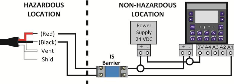
11 ELECTRICAL INSTALLATION Step Eight Wire Length The maximum length of wire connecting the transmitter and receiver is a function of wire size and receiver resistance. Wiring should not contribute more than 10% of the receiver resistance to total loop resistance. For extremely long runs (over 1000 feet), choose receivers with higher resistance to minimize the size and cost of connecting leads. Where wiring length is under 100 feet, wire as small as 22 AWG can be used. Wiring An external power supply delivering VDC with minimum current capability of 40 ma DC (per transmitter) is required to power the control loop. See Fig. A for connection of the power supply, transmitter and receiver. The range of appropriate receiver load resistance (RL) for the DC power supply voltage available is expressed by the formula: RLmax = (Vsup 10V) / 20 ma DC Shielded cable is recommended for control loop wiring. Use the Red wire as the (+) and the Black wire as the ( ). Wiring Control Drawing Fig. A Rev B MN of 16
:")


12 WIRING Step Nine Wiring to Loop Powered Display (refer to Control Drawing on previous page): Wiring to Generic PLC (refer to Control Drawing on previous page): Wiring to DataView LI55 Series Level Controller (refer to Control Drawing on previous page): Wiring to Commander LI90 Series Multi Tank Level Controller (refer to Control Drawing on previous page): 12 of 16 MN Rev B
: (Note: the LI25 series without backlight will have an added 2 VDC voltage drop) Wiring to DataLoop LI25 Series Level Indicator with Backlight (refer to Control Drawing")
13 WIRING Step Nine Wiring to DataPoint LC52 Series Level Controller (refer to Control Drawing on page 11): JWA mode (Factory Setting) Wiring to DataLoop LI25 Series Level Indicator w/o Backlight (refer to Control Drawing on page 11): (Note: the LI25 series without backlight will have an added 2 VDC voltage drop) Wiring to DataLoop LI25 Series Level Indicator with Backlight (refer to Control Drawing on page 11): (Note: the LI25 series without backlight will have an added 5.7 VDC voltage drop) Rev B MN of 16

. Distance from the receiver is limited only by total loop resistance. 2.")


14 INSTALLATION Step Ten The LD31 / LD32 series is designed to operate while submerged in the actual application liquid. Avoid installing the level transmitter along the bottom of the tank is materials such as sludge will build up and coat/cover the transmitter. This also includes any debris that will settle along the bottom of the tank. In these applications, it is best to suspend the transmitter above the highest level of sludge/debris that will occur. 1. Location: Select a location where the temperature of the transmitter will be between 0 and 176 F ( 18 to 80 C). Distance from the receiver is limited only by total loop resistance. 2. Position: The transmitter is not position sensitive. However all standard models are originally calibrated with the unit in a position with the pressure connection downward. Although they can be used at other angles, for best accuracy it is recommended that units be installed in the position calibrated at the factory. 3. Mounting: The transmitter can be mounted via several methods. It can be suspended from the electrical cable, it can be placed resting on the bottom of the tank in either horizontal or vertical orientation, or it can be attached to a pipe or hang wire by the 1/2 NPT male connection on the top of the housing. Interference: The DeltaSpan is designed to operate under the surface of the liquid in the tank. Avoid installations where other tank requirements will cause the transmitter to move or swing. For example: a mixer blade could cause the level transmitter to whip around within the tank. An alternative would be to move the transmitter to a more stable section of the tank or to install the LD31 series inside a still well/drop tube. The still well/drop pipe will minimize the effects created by the mixer. Termination: The cable for the DeltaSpan is typically terminated at a junction box located on top of the tank. Since the vent tube is contained within the cable, the pressure within the junction box must always be the same as the reference (typically atmospheric) pressure for the liquid. The inside of the junction box must be clean, dry and free of moisture. Add the optional pressure fitting (LD90 _001) to complete the package. The LD90 _001 features a 2 NPT thread for mounting and a liquid tight connector to seal the cable interface. Note: Use caution when sealing the cable at the top of the tank. The ventilation tube must be open and free to allow air to flow back to the pressure diaphragm. Avoid blocking the ventilation tube by compressing the cable. Always keep the cable termination clean, dry and free of moisture and prevent liquid from entering the vent tube. Note: A vent Filter is provided on the end of the vent tube. If the application requires the vent tube to be cut to length, then remove the vent filter and place on the end of the new end of the vent tube. Note: For extra protection against high humidity environments, Flowline offers the LD desiccant filter that can be attached to the vent tube. 14 of 16 MN Rev B
.")
15 MAINTENANCE Step Eleven After final installation of the pressure transmitter and its companion receiver, no routine maintenance is required. A periodic check of system calibration is suggested. The pressure transmitters are not field repairable and should be returned if repair is needed (field repair should not be attempted and may void warranty). Be sure to include a brief description of the problem plus any relevant application notes. Contact customer service to receive a return goods authorization number before shipping. Maintenance should consist of inspection to see that the transmitter is free from debris and not coated with any substance, which would prevent liquid from freely entering and leaving the transmitter. If this occurs, the transmitter should be cleaned. Testing the transmitter: First, verify that the sensor is wired correctly. Next, check if the power supply is providing the required power. Finally confirm that the loop resistance is not exceeding the sensor s specification. If transmitter is not functioning properly, isolate the transmitter from the system and wire as shown below. Be sure to remove the sensor from the classified area when performing this test. Multimeter should read 4 ma with the transmitter out of liquid. Rev B MN of 16
16 WARRANTY, RETURNS & LIMITATIONS Step Twelve Warranty Flowline warrants to the original purchaser of its products that such products will be free from defects in material and workmanship under normal use and service in accordance with instructions furnished by Flowline for a period of two years from the date of manufacture of such products. Flowline's obligation under this warranty is solely and exclusively limited to the repair or replacement, at Flowline's option, of the products or components, which Flowline's examination determines to its satisfaction to be defective in material or workmanship within the warranty period. Flowline must be notified pursuant to the instructions below of any claim under this warranty within thirty (30) days of any claimed lack of conformity of the product. Any product repaired under this warranty will be warranted only for the remainder of the original warranty period. Any product provided as a replacement under this warranty will be warranted for the full two years from the date of manufacture. Returns Products cannot be returned to Flowline without Flowline's prior authorization. To return a product that is thought to be defective, go to and submit a customer return (MRA) request form and follow the instructions therein. All warranty and non warranty product returns to Flowline must be shipped prepaid and insured. Flowline will not be responsible for any products lost or damaged in shipment. Limitations This warranty does not apply to products which: 1) are beyond the warranty period or are products for which the original purchaser does not follow the warranty procedures outlined above; 2) have been subjected to electrical, mechanical or chemical damage due to improper, accidental or negligent use; 3) have been modified or altered; 4) anyone other than service personnel authorized by Flowline have attempted to repair; 5) have been involved in accidents or natural disasters; or 6) are damaged during return shipment to Flowline. Flowline reserves the right to unilaterally waive this warranty and dispose of any product returned to Flowline where: 1) there is evidence of a potentially hazardous material present with the product; or 2) the product has remained unclaimed at Flowline for more than 30 days after Flowline has dutifully requested disposition. This warranty contains the sole express warranty made by Flowline in connection with its products. ALL IMPLIED WARRANTIES, INCLUDING WITHOUT LIMITATION, THE WARRANTIES OF MERCHANTABILITY AND FITNESS FOR A PARTICULAR PURPOSE, ARE EXPRESSLY DISCLAIMED. The remedies of repair or replacement as stated above are the exclusive remedies for the breach of this warranty. IN NO EVENT SHALL FLOWLINE BE LIABLE FOR ANY INCIDENTAL OR CONSEQUENTIAL DAMAGES OF ANY KIND INCLUDING PERSONAL OR REAL PROPERTY OR FOR INJURY TO ANY PERSON. THIS WARRANTY CONSTITUTES THE FINAL, COMPLETE AND EXCLUSIVE STATEMENT OF WARRANTY TERMS AND NO PERSON IS AUTHORIZED TO MAKE ANY OTHER WARRANTIES OR REPRESENTATIONS ON BEHALF OF FLOWLINE. This warranty will be interpreted pursuant to the laws of the State of California. If any portion of this warranty is held to be invalid or unenforceable for any reason, such finding will not invalidate any other provision of this warranty. For complete product documentation, video training, and technical support, go to For phone support, call from 8am to 5pm PST, Mon Fri. (Please make sure you have the Part and Serial number available.) 16 of 16 MN Rev B
DeltaSpan General Purpose Water Small Bore or Wastewater Pressure Level Transmitter LD34 and LD35 Series Manual
 DeltaSpan General Purpose Water Small Bore or Wastewater Pressure Level Transmitter LD34 and LD35 Series Manual LD34 Series Shown LD35 Series Shown Flowline, Inc. 10500 Humbolt Street Los Alamitos, CA
DeltaSpan Pressure Transmitters LD10 Series Owner s Manual
 Warranty, Service & Repair To register your product with the manufacturer, fill out the enclosed warranty card and return it immediately to: Flowline Inc. 10500 Humbolt Street Los Alamitos, CA 90720. If
T EK-SUB 4800C 19 mm Submersible Level Transmitter
 Technology Solutions T EK-SUB 4800C 19 mm Submersible Level Transmitter Instruction Manual Document Number: IM-4800C www.tek-trol.com Table of Contents 1 Safety Instructions... 2 1.1 Intended Use... 2
High-performance submersible pressure transmitter For level measurement Model LH-10
 Electronic pressure measurement High-performance submersible pressure transmitter For level measurement Model LH-10 WIKA data sheet PE 81.09 Applications Level measurement in rivers and lakes Deep well
PULSAR 5000 SERIES OPERATING & INSTALLATION INSTRUCTIONS SERIES 5000 PLEASE READ CAREFULLY BEFORE INSTALLING
 PULSAR 5000 SERIES OPERATING & INSTALLATION INSTRUCTIONS SERIES 5000 PLEASE READ CAREFULLY BEFORE INSTALLING Please Note: Ranges above 500mbar are designed and manufactured in accordance with sound engineering
FTS SUBMERSIBLE PRESSURE TRANSMITTER USER S MANUAL
 FTS SUBMERSIBLE PRESSURE TRANSMITTER USER S MANUAL TABLE OF CONTENTS PRODUCT OVERVIEW 2 I - USE AND CARE: 3 II - INSTALLATION: 5 III - GENERAL MAINTENANCE TIPS: 5 IV - APPENDIX: A-1 2-WIRE CURRENT LOOP
I/P Transducer Positioner Module
 I/P Transducer Positioner Module VRC P/N: 7958032 Installation, Operation and Maintenance Instructions 2.09 [53.1] 1.30 [32.9] 2.97 [75.5] 0.78 [19.8] 0.18 [4.4] 1.42 [36.1] n.18 MOUNTING HOLES (2) PLACES
L 100. Bubble-Tube Level System. Installation, Operation and Maintenance Instructions
 L 100 Bubble-Tube Level System Installation, Operation and Maintenance Instructions Figure 1 Contents Section Description Page 1.0 Introduction 2 2.0 Specifications 3 3.0 Installation 3 4.0 Warranty 6
Installation and Operation Manual
 Installation and Operation Manual WIKA FLR-SBDF / BLR-SBDF Magnetic Level Transmitter (Please retain for future usage) Contact: Gayesco-WIKA USA, L.P. 229 Beltway Green Boulevard Pasadena, TX 77503 www.wika.com
High-performance submersible pressure transmitter For level measurement Model LH-10
 Electronic pressure measurement High-performance submersible pressure transmitter For level measurement Model LH-10 WIKA data sheet PE 81.09 Applications Level measurement in rivers and lakes Deep well
! Unique Cable Seal System! Fully Temperature Compensated! Datalogger Compatible
 FEATURES! High Static Accuracy & Repeatability! Welded 316 SS or Titanium Construction! Small Rugged Package! User-Specified Pressure Ranges Available! 1% Computer-Tested, Calibrated and Serialized! Unique
CSA Sample Draw Aspirator Adapter Operator s Manual
 30-0951-CSA Sample Draw Aspirator Adapter Operator s Manual Part Number: 71-0367 Revision: 0 Released: 4/30/15 www.rkiinstruments.com WARNING Read and understand this instruction manual before operating
SDX Submersible Depth Transmitter User Manual
 SDX Submersible Depth Transmitter User Manual July 2017 USER INFORMATION Stevens makes no warranty as to the information furnished in these instructions and the reader assumes all risk in the use thereof.
SDX Submersible Depth Transmitter User Manual
 SDX Submersible Depth Transmitter User Manual October 2007 USER INFORMATION Stevens makes no warranty as to the information furnished in these instructions and the reader assumes all risk in the use thereof.
ISQB1 INTRINSICALLY SAFE ELECTRO-PNEUMATIC CONTROL VALVE INSTALLATION & MAINTENANCE INSTRUCTIONS HAZARDOUS AREA CLASSIFICATION
 PROPORTION AIR ISQB1 INTRINSICALLY SAFE ELECTRO-PNEUMATIC CONTROL VALVE INSTALLATION & MAINTENANCE INSTRUCTIONS Hazardous area classification Description / identification General specifications Connection
INSTALLATION & MAINTENANCE INSTRUCTIONS
 DESCRIPTION / IDENTIFICATION The QBX series valve uses Proportion-Air closed loop technology for Pressure control. It gives an output pressure proportional to an electrical command signal input. The QB1X
Pressure Measurement Single-range transmitters for general applications
 Siemens AG 07 Overview Function U const. p U I EM Sensor Connection for auxiliary power supply Vent pipe with humidity filter Protective conductor connection/ Equipotential bonding Diaphragm The pressure
WATER HEATER THERMAL EXPANSION TANKS Owner s Manual. Safety Instructions Installation Maintenance Warranty. Models: 2-5 Gallon Capacity
 WATER HEATER THERMAL EXPANSION TANKS Owner s Manual Safety Instructions Installation Maintenance Warranty Models: 2-5 Gallon Capacity Thank You for purchasing this Thermal Expansion Tank. Properly installed
INSTALLATION & MAINTENANCE INSTRUCTIONS DESCRIPTION SPECIFICATIONS. CE (EMC) Compliant
 Compliant") INSTALLATION & MAINTENANCE INSTRUCTIONS DESCRIPTION The QB3 is a closed loop pressure regulator consisting of two solenoid valves, internal pressure transducer, and electronic controls mounted to an integrated
INSTALLATION & MAINTENANCE INSTRUCTIONS DESCRIPTION The QB3 is a closed loop pressure regulator consisting of two solenoid valves, internal pressure transducer, and electronic controls mounted to an integrated
HAYWARD FLOW CONTROL TFS SERIES FLOW METER INSTALLATION, OPERATION AND MAINTENANCE INSTRUCTIONS
 HAYWARD FLOW CONTROL TFS SERIES FLOW METER INSTALLATION, OPERATION AND MAINTENANCE INSTRUCTIONS PLEASE READ THE FOLLOWING INFORMATION PRIOR TO INSTALLING AND USING HAYWARD TFS SERIES FLOW METERS. FAILURE
DPC-30 DPC-100. Reference Manual
 DPC-30 DPC-100 Reference Manual 1. Introduction 1.1 Description The Martel DPC Digital Pneumatic Calibrator improves upon traditional dial gauge pneumatic calibrators. The Martel DPC improves accuracy,
1 Overview. Pressure Measurement Single-range transmitters for general applications. 1/22 Siemens FI US Edition
 Siemens AG 07 SITRANS LH00 Transmitter for hydrostatic level Overview Function U const. p U I EM The pressure transmitter SITRANS LH00 is a submersible sensor for hydrostatic level measurement. The pressure
RK-IR Sample Draw Aspirator Adapter Operator s Manual
 30-0951RK-IR Sample Draw Aspirator Adapter Operator s Manual Part Number: 71-0018RK Revision: A Released: 6/2/10 www.rkiinstruments.com Product Warranty RKI Instruments, Inc. warrants gas alarm equipment
Operating Instructions for Intrinsically Safe Pressure Transmitters Series DMG/******** for Hazardous Application in Coal Mining Industry
 Operating Instructions for Intrinsically Safe ressure Transmitters Series DMG/******** for Hazardous Application in Coal Mining Industry Contents 1. Introduction 2. Abbreviations, symbols 3. Important
High-performance submersible pressure transmitter For level measurement in hazardous areas Model LH-20
 Electronic pressure measurement High-performance submersible pressure transmitter For level measurement in hazardous areas Model LH-20 WIKA data sheet PE 81.56 Applications Deep well and borehole measurements
High-performance submersible pressure transmitter For level measurement Model LH-20
 Electronic pressure measurement High-performance submersible pressure transmitter For level measurement Model LH-20 WIKA data sheet PE 81.56 Applications Deep well and borehole measurements Groundwater
92831 TEL: (714) FAX:
 FAX:") Document N0. 1800-03 Copyright 2010 Terra Universal Inc. All rights reserved. Revised Sept. 2010 Terra Universal, Inc. TerraUniversal.com 800 S. Raymond Ave. Fullerton, CA 92831 TEL: (714) 578-6000 FAX:
Document N0. 1800-03 Copyright 2010 Terra Universal Inc. All rights reserved. Revised Sept. 2010 Terra Universal, Inc. TerraUniversal.com 800 S. Raymond Ave. Fullerton, CA 92831 TEL: (714) 578-6000 FAX:
ASIC-Based Small Bore Submersible Level Transducer
 ASIC-Based Small Bore Submersible Level Transducer KPSI Transducers Series 340 FEATURES Custom Level Ranges up to 230 ft (70 m) H 2 O Unparalleled Performance - Static Accuracy: ±0.05% FS - Total Error
EchoSwitch. LU74, LU77 & LU78 Series Manual NEMA 4X Enclosure. Ultrasonic Level Switch and Transmitter
 EchoSwitch Ultrasonic Level Switch and Transmitter LU74, LU77 & LU78 Series Manual NEMA 4X Enclosure Flowline, Inc. 10500 Humbolt Street, Los Alamitos, CA 90720 p 562.598.3015 f 562.431.8507 w flowline.com
INSTRUCTION MANUAL. FLOW CONTROL DRAWERS MANUAL / PLC CONTROL SERIES Model Version Perma Pure LLC Tel:
 PERMA PURE INSTRUCTION MANUAL FLOW CONTROL DRAWERS MANUAL / PLC CONTROL SERIES Model 3300 Version 4.06 Perma Pure LLC Tel: 732-244-0010 P.O. Box 2105, 8 Executive Drive Tel: 800-337-3762 (toll free US)
TEK-SUB 4800B. Submersible Level Transmitter. Flow Level Temperature Pressure Valves Analyzers Accessories TekValSys LEVEL
 Technology Solutions TEK-SUB 4800B Submersible Level Transmitter LEVEL Flow Level Temperature Pressure Valves Analyzers Accessories TekValSys Introduction The Tek-Sub 4800B Submersible Level Transmitter
1 Overview. Pressure Measurement Single-range transmitters for general applications. 1/22 Siemens FI
 Siemens AG 06 SITRANS LH00 Transmitter for hydrostatic level Overview Function U const. p U I EM The pressure transmitter SITRANS LH00 is a submersible sensor for hydrostatic level measurement. The pressure
EchoSwitch Ultrasonic Level Switch and Transmitter LU74, LU77 & LU78 Series Manual
 EchoSwitch Ultrasonic Level Switch and Transmitter LU74, LU77 & LU78 Series Manual Flowline Inc. 10500 Humbolt Street Los Alamitos, CA 90720 Tel: (562) 598 3015 Fax: (562) 431 8507 www.flowline.com Rev
High-performance submersible pressure transmitter For level measurement Model LH-20
 Electronic pressure measurement High-performance submersible pressure transmitter For level measurement Model LH-20 WIKA data sheet PE 81.56 Applications Deep well and borehole measurements Groundwater
Modbus Submersible Level Transducer
 ISO-91:2 Certified Modbus Submersible Level Transducer KPSI Transducers Series 51 FEATURES! Level Ranges up to 23 ft (7 m) H 2 O! Accuracy of ±.1% Total Error Band! RS-485 Communication Interface with
P499 Heavy Duty Pressure Transducer
 P499 Heavy Duty Pressure Transducer Product Bulletin Code No. LIT-??? E Issued 11 2006 The P499 Series is a new global Pressure Transducer with an excellent price performance ratio. The P499 exceeds the
HAYWARD FLOW CONTROL Series PBV Back Pressure Valve and Series RPV Pressure Relief Valve INSTALLATION, OPERATION, AND MAINTENANCE INSTRUCTIONS
 HAYWARD FLOW CONTROL Series PBV Back Pressure Valve and Series RPV Pressure Relief Valve INSTALLATION, OPERATION, AND MAINTENANCE INSTRUCTIONS Page 1 of 20 Page 2 of 20 TABLE OF CONTENTS Safety Warnings
Instruction Manual for Intrinsically Safe - Reed Switches
 Instruction Manual for Intrinsically Safe - Reed Switches Option Code: -1S2-IS-LED or -2S2-IS-LED -1S2-IS or -2S2-IS ATEX RCM Industries, Inc. Direct Reading Differential Pressure Flowmeters 110 Mason
RK LEL Sample Draw Aspirator Adapter Operator s Manual
 30-0951RK LEL Sample Draw Aspirator Adapter Operator s Manual Part Number: 71-0017RK Revision: A Released: 6/2/10 www.rkiinstruments.com Product Warranty RKI Instruments, Inc. warrants gas alarm equipment
9700 Transmitter Submersible hydrostatic level transmitter
 Specification sheet IP0078 October 2007 Level 9700 Transmitter Submersible hydrostatic level transmitter Description The 9700 series hydrostatic level transmitter is designed to perform in the most arduous
DTG - LCD Digital Temperature Gauge USER MANUAL
 DTG - LCD USER MANUAL Page 1 of 7 USERS GUIDE page 1. Description 3 2. Function 3 3. Safety Instruction 3 3.1. Safety Conventions 3 3.2. Proper Use 3 4. Installation 4 4.1. Unpacking 4 4.2. Storage 4 4.3.
SSFU SUPER SPRAYFAST UNIVERSAL ADHESIVE APPLICATOR
 S S F U SSFU SUPER SPRAYFAST UNIVERSAL ADHESIVE APPLICATOR MACHINERY DIVISION OWNER S MANUAL UNIT INSTRUCTIONS Please follow all SSFU Safety Instructions. Contact your Duro Dyne Tech Service if you have
DFB FLOW METERS (DESIGNED FOR BLENDERS, DUAL TAPER)
") DFB FLOW METERS (DESIGNED FOR BLENDERS, DUAL TAPER) 0-3, 0-15, 0-30 & 0-70 LPM ASSEMBLY INSTRUCTIONS & INSTRUCTIONS FOR USE R219P87-400 (0-70 LPM) R219P88-400 (0-30 LPM) R219P79-400 (0-15 LPM) R219P99-400
DFB FLOW METERS (DESIGNED FOR BLENDERS, DUAL TAPER) 0-3, 0-15, 0-30 & 0-70 LPM ASSEMBLY INSTRUCTIONS & INSTRUCTIONS FOR USE R219P87-400 (0-70 LPM) R219P88-400 (0-30 LPM) R219P79-400 (0-15 LPM) R219P99-400
TRANSDUCER KIT 2 INSTALLATION INSTRUCTIONS
 TRANSDUCER KITS INSTALLATION INSTRUCTIONS ELECTRICAL SHOCK HAZARD Disconnect power before installing or servicing this product. A qualifi ed service person must install and service this product according
Deep Submersible Level Transducer Series 300DS
 KPSI Transducers Deep Submersible Level Transducer Series 300DS FEATURES! Custom Level Ranges up to 4614 ft (1408 m) H 2 O! Accuracy of ±0.5% FS! Analog Outputs of 4-20 ma or 0-5 VDC! Welded 316 SS Construction!
EcoPRO-Series 4-20mA SUBMERSIBLE PRESSURE TRANSMITTER INSTRUCTIONS
 EcoPRO-Series 4-20mA SUBMERSIBLE PRESSURE TRANSMITTER INSTRUCTIONS EcoPRO-Series 4-20mA SUBMERSIBLE PRESSURE TRANSMITTER INSTRUCTIONS 9001:2008 ISO CERTIFIED COMPANY Table of Contents Introduction - EcoPRO-Series
TOP VALVE. Pat. #5,857,486 & 5,944,050. Mid-Range Pressure PSIG Back Pressure and Pressure Relief Valves. Instruction Manual
 TOP VALVE Pat. #5,857,486 & 5,944,050 Mid-Range Pressure 50 232 PSIG Back Pressure and Pressure Relief Valves Instruction Manual Please Note: This instruction manual provides detailed information and instructions
L (up to 25 m) Electronic part. working temp.: Ñ IP 66 / IP67. Mounting bracket ÐÑ. Sensor type. working temp.:
 Electronic part. working temp.: Ñ IP 66 / IP67. Mounting bracket ÐÑ. Sensor type. working temp.:") Smart level probe type APC-2000ALW/L Programmable zero shift, range and damping ratio 4...20 ma output signal + HART protocol Accuracy 0,16% Local display Intrinsic safety certificate (ATEX, IECEx) II
Smart level probe type APC-2000ALW/L Programmable zero shift, range and damping ratio 4...20 ma output signal + HART protocol Accuracy 0,16% Local display Intrinsic safety certificate (ATEX, IECEx) II
OPTIBAR P 1010 C Technical Datasheet
 Technical Datasheet Pressure transmitter with recessed diaphragm for general applications Wide variety thanks to modular design Measuring ranges up to 250 bar / 3750 psi High overload and temperature stability
Calibration Gas Instrument INSTRUCTION MANUAL. Release I. Advanced Calibration Designs, Inc.
 Advanced Calibration Designs, Inc. Calibration Gas Instrument INSTRUCTION MANUAL Release I www.goacd.com Instruction Manual Gas Generator Release I TABLE OF CONTENTS I. General Description Page 2 II. Start-Up
ACRYLIC FLOW METERS 0-30, 0-70 & LPM
 ACRYLIC FLOW METERS 0-30, 0-70 & 0-120 LPM ASSEMBLY INSTRUCTIONS & INSTRUCTIONS FOR USE R219P86 (0-120LPM) R219P87 (0-70LPM) R219P88 (0-30 LPM) R138P11 Rev. D TABLE OF CONTENTS: 1.0 PRODUCT OVERVIEW...1
GEMS SENSORS & CONTROLS
 GEMS SENSORS & CONTROLS OPERATING & INSTALLATION INSTRUCTIONS 31XX / 32XX SERIES PLEASE READ CAREFULLY BEFORE INSTALLING Part Number: 560550-0076 Issue: E INTRODUCTION Series 3100/3200 high output pressure
NB/NBR NITROGEN BOOSTER FOR AVIATION SERVICE
 NB/NBR NITROGEN BOOSTER FOR AVIATION SERVICE INSTALLATION, OPERATION & MAINTENANCE MANUAL INTERFACE DEVICES, INC. 230 Depot Road, Milford, CT 06460 Ph: (203) 878-4648, Fx: (203) 882-0885, E-mail: info@interfacedevices.com
User s Guide Temperature Sensor Converter TSC-599
 User s Guide Temperature Sensor Converter TSC-599 ILX Lightwave Corporation 31950 Frontage Road Bozeman, MT, U.S.A. 59715 U.S. & Canada: 1-800-459-9459 International Inquiries: 406-556-2481 Fax 406-586-9405
High-performance submersible pressure transmitter For level measurement Model LH-20
 Electronic pressure measurement High-performance submersible pressure transmitter For level measurement Model LH-20 WIKA data sheet PE 81.56 Applications Deep well and borehole measurements Groundwater
97C COMPRESSOR KIT 12V PART NO C COMPRESSOR KIT 24V PART NO C COMPRESSOR KIT PART NO
 97C COMPRESSOR KIT 12V PART NO. 00097 97C COMPRESSOR KIT 24V PART NO. 02497 98C COMPRESSOR KIT PART NO. 00098 97C 98C IMPORTANT: It is essential that you and any other operator of this product read and
E2K-L. Liquid Level Sensor That Is Unaffected by the Color of the Pipe or Liquid. Liquid Level Sensor. Ordering Information
 Liquid Level EK-L CSM_EK-L_DS_E 3 Liquid Level That Is Unaffected by the Color of the or Liquid Mount to bypass pipes. Fit a wide range of pipe diameters: 8 to mm or to mm Built-in Amplifiers to save space.
Model PDT Dewpoint Transmitter
 Model PDT Dewpoint Transmitter Instruction Manual Alpha Moisture Systems Alpha House 96 City Road Bradford BD8 8ES England Tel: +44 1274 733100 Fax: +44 1274 733200 email: mail@amsytems.co.uk web: www.amsystems.co.uk
Model B-1 Pipe Line Strainer 3, 4, 6 & 8 Inch (DN80, DN100, DN150 & DN200) 175 psi (12,1 bar) General Description. Technical Data
 175 psi (12,1 bar) General Description. Technical Data") Technical Services: Tel: (800) 381-312 / Fax: (800) 71-5500 Customer Service/Sales: Tel: (215) 362-0700 / (800) 523-6512 Fax: (215) 362-5385 Model B-1 Pipe Line Strainer 3,, 6 & 8 Inch (DN80, DN100, DN150
Technical Services: Tel: (800) 381-312 / Fax: (800) 71-5500 Customer Service/Sales: Tel: (215) 362-0700 / (800) 523-6512 Fax: (215) 362-5385 Model B-1 Pipe Line Strainer 3,, 6 & 8 Inch (DN80, DN100, DN150
INSTRUCTION MANUAL MP4AR Remote Convection Gauge Range: 1 x 10⁻³ Torr to 1 x 10+3 Torr
 INSTRUCTION MANUAL MP4AR Remote Convection Gauge Range: 1 x 10⁻³ Torr to 1 x 10+3 Torr A DIVISION OF THE FREDERICKS COMPANY 2400 PHILMONT AVE. HUNTINGDONVALLEY, PA 19006 PARTS LIST 1 3 4 2 # QTY ITEM DESCRIPTION
210 Series Transmitter with External Electrochemical Sensor
 210 Series Transmitter with External Electrochemical Sensor INSTRUCTIONS Installation and Operation of the AMC-210 Series Transmitter with External Electrochemical Sensor IMPORTANT: Please read these installation
P9000 DESCRIPTION. For parts requiring RoHS compliance, please contact factory. P February /6
 P9000 High accuracy through digital compensation High thermal stability Rugged stainless steel construction Ideal for test stands High burst pressure limit DESCRIPTION The P9000 Series is a range of advanced,
LVU2800 Series. Ultrasonic Level Transmitter
 LVU2800 Series Ultrasonic Level Transmitter 2 of 23 INTRODUCTION / TABLE OF CONTENTS Step One The LVU2800 Series is a general purpose ultrasonic level transmitter that provides a loop powered 4 20 ma output.
GAS FUEL VALVE FORM AGV5 OM 8-03
 ALTRONIC AGV5 OPERATING MANUAL GAS FUEL VALVE FORM AGV5 OM 8-03 WARNING: DEVIATION FROM THESE INSTALLATION INSTRUCTIONS MAY LEAD TO IMPROPER ENGINE OPERATION WHICH COULD CAUSE PERSONAL INJURY TO OPERATORS
92831 TEL: (714) FAX:
 FAX:") Document No. 1800-75 Respiration Test Chamber Copyright 2010 Terra Universal Inc. All rights reserved. Revised September 2010 Terra Universal, Inc. TerraUniversal.com 800 S. Raymond Ave. Fullerton, CA
Document No. 1800-75 Respiration Test Chamber Copyright 2010 Terra Universal Inc. All rights reserved. Revised September 2010 Terra Universal, Inc. TerraUniversal.com 800 S. Raymond Ave. Fullerton, CA
SDS -Series 4C-D201/-D202 Supplemental Drying System User s Manual
 SDS -Series 4C-D201/-D202 Supplemental Drying System User s Manual 8 Executive Drive P.O. Box 2105 Toms River, NJ 08754 (732) 244-0010 (800) 337-3762 fax (732) 244-8140 www.permapure.com info@permapure.com
DF-310E PROCESS ANALYSERS APPLICATIONS FEATURES
 PROCESS ANALYSERS DF-310E The DF-310E is a Coulometric sensor based oxygen analyzer designed to measure trace and percent level oxygen in pure and multi-gas backgrounds for process and quality control
SITRANS P measuring instruments for pressure
 SITRANS P measuring instruments for pressure Z series for gage pressure Siemens AG 008 Overview Design The main components of the pressure transmitter are: Brass housing with silicon measuring cell and
P900. P900, Datenblatt Seite 1 DESCRIPTION
 , Datenblatt Seite 1 Field proven rugged construction High overpressure capability High reliability for demanding environments Application specific customization Excellent media compatibility Shock and
Model C Pipe Line Strainer 6, 8 & 10 Inch (DN150, DN200 & DN250) 250 psi (17,2) General Description. Technical Data. Page of 6 MAY, 2006 TFP1644
 250 psi (17,2) General Description. Technical Data. Page of 6 MAY, 2006 TFP1644") Technical Services: Tel: (00) 31-9312 / Fax: (00) 791-5500 Model C Pipe Line Strainer 6, & 10 Inch (150, & 250) 250 psi (17,2) General Description The welded steel body Model C Pipe Line Strainers (Ref.
Technical Services: Tel: (00) 31-9312 / Fax: (00) 791-5500 Model C Pipe Line Strainer 6, & 10 Inch (150, & 250) 250 psi (17,2) General Description The welded steel body Model C Pipe Line Strainers (Ref.
Air Sensor. FCS Ex. Manual. AQ Elteknik AB
 Air Sensor FCS Ex Manual AQ Elteknik AB Air Sensor Model FCS Ex Manual version 2.0 Oct 2010 AQ Elteknik AB AQ Elteknik AB Air Sensor Manual 2 Table of contents 1. Manufacturer information... 4 Manufacture
J21K Series DIFFERENTIAL PRESSURE SWITCH. features
 DIFFERENTIAL PRESSURE SWITCH J21K Series features Sealed Metal Bellows Sensors Welded 316 Stainless Steel Sensors Gasketed Die-Cast Aluminum Enclosure with Epoxy Coating Single Switch Output Adjustable
AUTO PUMP STATUS CENTER
 INSTRUCTION MANUAL AUTO PUMP STATUS CENTER PRESSURE ONLY MODEL #: 091-198-12-AP File: IM_091-198-12-AP_revD.indd Rev: D, pg 3 WD Revised By: PSS Date: 2-01-2016 3 YEAR WARRANTY INTRODUCTION The Auto Pump
RGC-IR Remote Gas Calibrator for IR400
 Remote Gas Calibrator for IR400 The information and technical data disclosed in this document may be used and disseminated only for the purposes and to the extent specifically authorized in writing by
3.0 Pressure Transmitter Selection
 3.0 Pressure Transmitter Selection Each Tronic Line pressure transmitter has different features to meet specific performance, environmental, and price requirements. It is not possible to describe every
EASIDEW TRANSMITTER with Current Source Output
 EASIDEW TRANSMITTER with Current Source Output INSTALLATION, OPERATION AND MAINTENANCE MANUAL Issue March 2002 2 TABLE OF CONTENTS SECTION PAGE 1. INTRODUCTION 3 1.1 General 3 1.2 Ceramic Sensing Element
! Warning, refer to accompanying documents.
 About this Manual To the best of our knowledge and at the time written, the information contained in this document is technically correct and the procedures accurate and adequate to operate this instrument
Electro-Pneumatic Converter YT-940 SERIES
 Electro-Pneumatic Converter YT-940 SERIES PRODUCT MANUAL VERSION 1.00 Contents 1. Introduction 3 1.1 General information for the users. 3 1.2 Manufacturer Warranty 3 1.3 Explosion Proof Warning. 4 2. Product
3 GALLON, OILLESS PANCAKE COMPRESSOR INSTRUCTIONS. Item #31289
 3 GALLON, OILLESS PANCAKE COMPRESSOR INSTRUCTIONS Item #31289 The EASTWOOD 3 GALLON, OILLESS PANCAKE COMPRESSOR, with an Integral Air Regulator, efficiently supplies all compressed air requirements for
DF-550E PROCESS ANALYSERS APPLICATIONS FEATURES
 PROCESS ANALYSERS DF-550E The DF-550E Nano Trace oxygen analyser is a Coulometric sensor based analyser designed to measure oxygen as a contaminant at ultra trace levels in ultra high purity electronic
E8AA. Pressure Sensor of Stainless Steel Construction Is Ideal for a Wide Range of Applications. Pressure Sensor (Stainless Steel Diaphragm)
") Pressure Sensor (Stainless Steel Diaphragm) CSM DS_E_3_1 Pressure Sensor of Stainless Steel Construction Is Ideal for a Wide Range of Applications Incorporates double diaphragms consisting of SUS316L stainless
Pressure Sensor (Stainless Steel Diaphragm) CSM DS_E_3_1 Pressure Sensor of Stainless Steel Construction Is Ideal for a Wide Range of Applications Incorporates double diaphragms consisting of SUS316L stainless
The Univentor 1250 Anaesthesia Unit
 THE UNIVENTOR 1200/1250 ANAESTHESIA UNIT The Univentor 1250 Anaesthesia Unit TABLE OF CONTENTS EDITION 1 Section 1 - WARRANTY & SERVICE 1.1. WARRANTY 2 1.2. DAMAGED SHIPMENTS 2 1.3. SERVICE 2 Section 2
Air Sensor. SAC Ex. Manual ATEX. AQ Elteknik AB
 Air Sensor SAC Ex Manual AQ Elteknik AB ATEX Air Sensor SAC Ex ATEX Certified model Manual version 2.1 April 2014 AQ Elteknik AB 2 Table of contents 1. Manufacturer information... 4 Manufacture Declaration
2 Overview. SITRANS P measuring instruments for pressure. Transmitters for gage and absolute pressure. Z series for gage pressure
 Z series for gage pressure Overview Design The main components of the pressure transmitter are: Brass housing with silicon measuring cell and electronics plate Process connection Electrical connection
Autocalibration Systems For In Situ Oxygen Analyzers
 Product Data Sheet PDS 106-340AC SPS 4000, IMPS 4000, and MPS 3000 January, 1999 Autocalibration Systems For In Situ Oxygen Analyzers Cost-effective autocalibration systems for installations ranging from
MODEL GT820 OXYGEN SENSOR
 INSTRUCTION MANUAL MODEL GT820 OXYGEN SENSOR 70046 The information and technical data disclosed by this document may be used and disseminated only for the purposes and to the extent specifically authorized
Accu-Tab Systems 1000 Series by Axiall Corporation
 Accu-Tab Systems 1000 Series by Axiall Corporation Installation and Operating Instructions Model 1050 DANGER: DO NOT MIX CHEMICALS! The Accu-Tab chlorinator is designed for use with Axiall approved tablets
Hidrostatic Level DATASHEET
 Hidrostatic Level DATASHEET JUNHO 2013 Hydrostatic level probes SGE-25 and SGE-16 SG cable hanger Red (+) Capillary Black ( ) PP junction box Any measurement range from 1 up to 500 m H 2 O Integrated internal
Type N-10, N-11 Hazardous Area Non-incendive Transmitters
 Electronic Pressure Catalog > Hazardous Area > N-10, N-11 Type N-10, N-11 Hazardous Area Non-incendive Transmitters Applications Natural gas compressors Wellhead monitoring Pipeline pressure General industrial
Features. Description
 Features Fast response flow meter ideal for inert gas and liquid mass flow measurement applications Smart electronics permit field adjustment of critical flow meter settings Field validation of flow meter
Norrsken Family Booklet
 Section 1: Introduction Low Energy Designs produce efficient and effective LED based lighting products for commercial, retail and industry purposes. Each product may contain specific details on its operation
Series 8500 Expansion Compensators. Catalog 674H
 Series 8500 Expansion Compensators Catalog 674H 500 Laminated Bellows Expansion J Series 8500 on Joints Expansion Compensators Sizes 3/4" through 4" Threaded, welded, flanged and grooved steel pipe joints
Mini-Pro CO2 Sensor User s Manual - ANALOG MODEL -
 Mini-Pro CO2 Sensor User s Manual - ANALOG MODEL - Table of Contents 1. Introduction 3 2. Instrument Setup 4 2.1 Instrument Checklist 4 2.2 Optional Accessories 4 2.3 Gas Concentration Ranges Available
Pressure Measurement Single-range transmitters for general applications
 Siemens A 207 Overview Application The SITRANS P Compact pressure transmitter is designed for the special requirements of the food, pharmaceutical and biotechnology industries. The use of high-grade materials
BUBBLER CONTROL SYSTEM
 BUBBLER CONTROL SYSTEM Description: The HDBCS is a fully automatic bubbler system, which does liquid level measurements in water and wastewater applications. It is a dual air compressor system with, air
Media-Isolated Mag Plus Probe Low Pressure-ISO Kit
 Manual No: 577013-975 Revision: B Media-Isolated Mag Plus Probe Low Pressure-ISO Kit Installation Guide Notice Veeder-Root makes no warranty of any kind with regard to this publication, including, but
Aquavar SOLO 2 Frequently Asked Questions
 Aquavar SOLO 2 Frequently Asked Questions How do I size the Aquavar SOLO 2 for the appropriate pump/motor combination? Can I use a 208 Volt motor? Can I run the Aquavar SOLO 2 up to 80HZ? What are the
TOP VALVE. Pat. #5,857,486 & 5,944,050. High Temperature: max. 300 F (149 C) Back Pressure And Pressure Relief Valves. Instruction Manual
 Back Pressure And Pressure Relief Valves. Instruction Manual") TOP VALVE Pat. #5,857,486 & 5,944,050 High Temperature: max. 300 F (149 C) Back Pressure And Pressure Relief Valves Instruction Manual PLEASE NOTE: This instruction manual provides information and instructions
TOP VALVE Pat. #5,857,486 & 5,944,050 High Temperature: max. 300 F (149 C) Back Pressure And Pressure Relief Valves Instruction Manual PLEASE NOTE: This instruction manual provides information and instructions
Expert Hydrostatic Level Transmitters
 Expert Hydrostatic s General Features MJK Expert hydrostatic level transmitters are designed for level measurement by submerging the transmitter in open channels, drains and tanks. Expert hydrostatic level
Model PSI Compressor with 3-Gallon Air Tank 12VDC
 Model 6350 150 PSI Compressor with 3-Gallon Air Tank 12VDC IMPORTANT: It is essential that you and any other operator of this product read and understandd the contents of this manual before installing