Spilt body Flange ball valve. TC-205MFF-PN1640 User Manual English Version. Document No: TC-205MFF-PN1640.Ur-manual. Date: 2007/04/2617. Version: 1.
|
|
|
- Derick Barrett
- 5 years ago
- Views:
Transcription
1 Spilt body Flange ball valve TC-205MFF-PN1640 Series PED Category I,II TC-205MFF-PN1640 User Manual English Version Use for company in Europe who will place the product on the market, please amend which necessary. Document No: TC-205MFF-PN1640.Ur-manual Date: 2007/04/2617 Version: 1.0
2 Form No. QF
3 a. Material Selection: The possibility of material deterioration in service and the need for periodic inspections is depended on the contained fluid. Carbide phase conversion to graphite, oxidation of ferrite materials, decrease in ductility of carbon steels at low temperature (even in applications above -29 ) are among those items. Even information about corrosion data is provided in this user manual, the user is requested to take attention or consideration to determine the suitability of material in their application. b. Pressure-Temperature rating: The Pressure-Temperature rating is considered for static pressure. Please refer to P & T rating section on page 9 for working precaution. The allowable temperature is between R.T. and 160 do not exceed the temperature range to avoid danger accident happen. c. Fluid thermal expansion: It is possible, when the ball valve is in closed condition, the sealed cavity within the valve body to be filled with liquid. If this liquid is not released, by partially opening the valve or some other means, and it is subject to a temperature increase, excessive pressure sufficient to cause pressure boundary failure can be generated. However our products have pressure self-relief seat to prevent pressure built up, user is recommended to prevent that the pressure in the valve will not exceed that allowed pressure, by means of piping design, installation, or operation procedure. d. Static electric effect: The ball valves are provided with anti-static devices for ball-stem-body. When service conditions require electrical continuity to prevent static discharge, the user is responsible for specifying static grounding. e. Fire safe condition: Generally, the application of the valve shall comply with the Pressure-Temperature rating range. If the risk of fire is major effect, user is recommended to select our fire-safe products, which with API-607 approval. Contact to the valve distributor or manufacturer for details. f. Liquids with high fluid velocity: When ball valves must be operated frequently on liquids with very high velocity, a check shall be made with the valve distributor or manufacturer for appropriate advice to minimize the possibility of seat deformation, especially when they are highly pressurized on high-temperature line. g. Throttling service: Ball valves are generally not recommended for throttling service, where both the fluid flow and the leading edge of the ball can damage or deform the resilient ball seats causing leakage. High fluid velocity or the presence of solid particles in suspension will further reduce seat life in throttling applications. Form No. QF
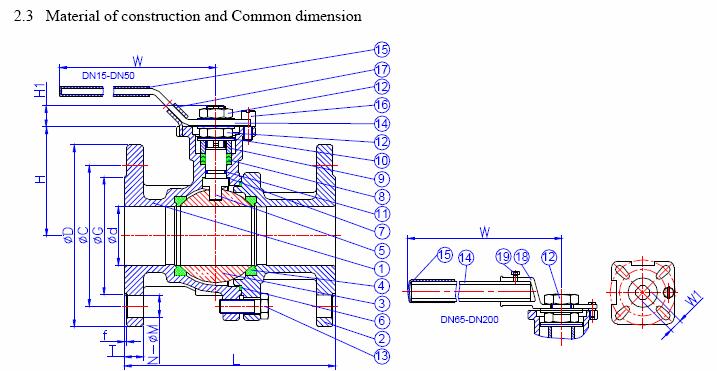
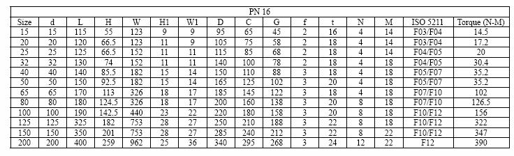
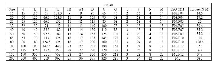
4 h. Do not open the bonnet or cap when bearing pressure. Valve is not equipped with pressure access device. User should check it by other method through its piping system. i. No touch the surface of valve on high temperature. j. Not allowed for unstable fluid, otherwise specified with catogory III in Declaration of conformity or/and in this user manual. k. Lock design on the handle to avoid the valve operated by non-related people is optional requested by the user. 2. Product Description 2.1 Feature a. FULL BORE ball valve. b. Direct-mounting of actuator to valves, low cost and easy automation c. Bottom Entry Blow-Out Proof Stem design Provides Maximum Safety. d. Anti-static devices for ball-stem-body. e. Integral Twin pattern ISO 5211 mounting pad for double active & spring return actuator. f. Heavy-duty body & end cap construction with traceable heat number. g. Self-adjusting stem packing assembly with Belleville spring for temperature fluctuations, vibration, and is secured. h. Pressure self-relief seat to prevent pressure built up. i. Lock design on the handle is optional requirement. 2.2 Product specification The scope of product specifications are as following. The category levels we wsed, and in according to group 1, gas fluid, because we are hard to know the application of end user sizes under and including DN 25 or 1 valves will not be bean a CE mark in according to the PED directive. Form No. QF
5

6 4. Pressure Temperature Ratings The pressure-temperature rating of ball valves are determined, not only by valve shell materials, but also by sealing materials used for ball seats, stem packings, and body seal. Sealing materials may be high molecule, elasticity and hardness, however, the choice is limited by the characteristics of the service fluid, temperature, pressure, velocity of fluid, frequency of valves operation and sizes of ball valves etc, Followings are the general rating charts for non-shock fluid service for floating ball valves distinguished by sizes and seating materials, please refer to section 1, General precaution. Form No. QF
7 5. Delivery Condition and Storage Valves stay in the open condition during the transportation. For incoming QC, it must check: a. Packing condition: Is there any damaged during the transportation. b. The bolts of cap and yoke: to make sure the bolt does not loose tightness when it arrived. Valves must store in an indoor warehouse to avoid dusts and other foreign object, do not exposed in an open space without to put a cover over or take off the packing under an unnecessary situation. 6. Installation and Operation 6.1 Handling During the ball valve installation, it must follow the procedure to hand at the both side of the bodies, the cable must be strong enough to ensure the safety during the installation. 6.2 Cleaning Even the valves was transported under a clean environment, operator must check is there any foreign body or dusts inside the bore. If yes, clean it before installation. Operator clean the valves by water, compression air, or steam (automation valve shall be cleaned only with water or steam, the compression air is not allowed.) For cleaning operation, first step is put the valve bore perpendicular to the ground and clean, ensure all the dusts can be removed from the bore. The second step is checking and clean all the connecting pipe bore and connection area. No flush, rust and foreign bodies allow to avoid the blocking and leakage. 6.3 Valve Installation (Install to the pipeline system) a. Direction Most of the valves do not restrict the flow direction. b. Position The body, cap and gasket are in the connection area of ball valve and pipeline. The bear weight ability and gradient are very important to the pipe installation. Do not make the pressure from the pipeline and stress to concentrate on the connecting area of body and cap. It will cause the deformed and leakage, and the ball, seat, and stem will stick, leaking, and damaged. c. Fittings Select the correct specification of bolts to fasten the flange with pipeline. Following table show fitting information, which is according to DIN 2545 & DIN Form No. QF

8 To tight the bolts of the flange end caps, the force must distribute on the every single bolt evenly. The order to tight the bolts need to install symmetrically. See the drawings below. Please see the drawings below for the order of bolts installation. d. Systems hydrostatic test Before delivery, valves are tested 1.5 times the allowable pressure at ambient temperature in open position. After installation, the piping system may subject to system tests, as condition not to exceed the above mentioned pressure. 6.4 Actuator installation The ball valves are provided with ISO 5211 actuator attachment. Following is the flange type against sizes of the ball valves. Form No. QF
9 The sizes of actuator and setting of the input power or pressure of actuator are depended on the operation torque. The following table lists the maximum torque values of each flange type. User is recommended to refer to the instruction of actuator supplier. Overload torque applied by the actuator may transfer the un-intended load to ball valve itself or to the piping joints. Setting of the input power or pressure of the actuator is better not to exceed 1.5 times of the operation torque data. 6.5 Operation a. For manual operation, shift the handle in counter clockwise direction for close and clockwise for opening. b. If the handle is in parallel position with the flow direction, the valve is open. If the handle is in right angle position with the flow direction, the valve is close. c. When installing actuator or the valve is operated with removable handle, the user should ensure the position of the valve whether open or close. There is sign at the top of stem for square type stem. Following with the fig-4. Showing how to access the position of ball valve. Form No. QF
10 7. Put into service 7.1After install to the pipe line, it is necessary to check the function of the product. Thus, operate the valve about 3 times to ensure the function. 7.2The whole pipe line system may be tested with a proper pressure. User shall take care that the testing pressure shall not be exceeded 1.5 times the allowed working pressure. 7.3After pressure testing, user shall operate the valve again about 3 times to ensure the function. 8. Dangers of inappropriate use 8.1 Never use the product exceed its allowed condition, such as pressure, temperature and fluid. 8.2 If the product have any inappropriate use, the product was damage however there are no signal occur immediately. User shall change the product to avoid danger in the future. 9. Maintenance 9.1 Maintenance frequency The maintenance frequency is determined upon the application of ball valve. User shall consider the time interval depend on the kinds of fluid, flow velocity, operation frequency, high-pressure effect and high-temperature effect etc. minimum wall thickness acc to tab 3.2 etc. 9.2 Disassembly a. The user should check the kit of TC-205MFF-PN16 if available in the local market, if not, please do not disassembly the valve, otherwise, please make a order from the original manufactory for the kit of TC-205MFF-PN16. b. To dismantle the valve must follow the procedure and drawings below. c. It doesn t matter where is the position of valve located, usually it contained the seal up fluid, so operator must be very carefully when move the valve on the pipe. It must open the ball a little and let the fluid come out slowly, it also need to watch out the poisonous and inflammability objects if there is any. d. It must turn the ball in the close position before dismantle the valve. The ball cannot be taken out from valve body if the ball is in the open or semi-open position. The right position for store the valve is put the flange end on the ground. If it is a valve with the hand wheel, than it must dismantle the hand wheel from the valve first than put the valve flange end on the ground. This procedure is protecting the surface of the ball. e. To dismantle the valve body and end cap, release the bolts symmetrically. It must be careful to dismantle the ball to avoid the seat retainer fall down from end cap. Form No. QF
11 f. To lift the ball by hoist, it must make the protection on corner to avoid the ball damaged by metal contacted. 9.3 Parts inspection, maintenance and replacement: a. Check the surface of ball is it scraped? It may use the PT for inspection if necessary. If there is any damaged on the surface, than found out the root cause such as the dirt fluid etc. It must avoid the damage factors as far as possible. b. The damaged of the ball surface, to gauge is it located on the contacting area of ball and ball seat? If it is the case, than the ball must take a fine milling. If it cause a heavy damaged, than it must welded and re-machined again. If it cannot be repaired than change a new ball. c. If the scraped area is not at the location described in the item b above, than it must re-fine milling the damage area again. Otherwise, the ball will damage the soft seat during the open and close operation or it will dig out the ball seat and cause a heavy damage to ball and seat. d. To inspect the surface of soft seat, has it any scrape mark, concave, dusts (including weld dregs, iron bit, sands etc.), abrasion, abnormal press scrape, and a tiny scrape. Usually, the scrape mark and damage by dusts will occur the same time as ball damaged. It is the root cause for leakage. If leakage occur before repairing, than suggest to change a new soft seat. The mark from press or fine scrape is happen in an abnormal operation pressure. It must reconsider to choice a right valve. Form No. QF
12 e. The stem packing may be replaced by the new parts after dismantle the valve. User shall make sure that the your distributor able to serve the same packing of your valve if you do not have a service pack. To tight the bolt and nut, please see Section 8 for torque data. f. To do the final inspection for a valve, it must operate 10 times of open and close to ensure all the parts are assemble correctly. To ensure the torque in a same value during the open/close operation. If the torque is not the same in operation, than it may has some parts in a not corrected position or interference. It must dismantle and re-assembly. Otherwise, it is easy to damage if let this valve works on a pipeline under higher pressure. 9.4 Assembly For assembly process, it takes the opposite way of dismantle process. The must in the close position during assembling the body and end cap, the stopper must be located at the right place, otherwise, the open and close operation will be opposite. 10. Torque Data Form No. QF
13
14
15
16
17
18
19
20
21
22
23
24
25
26
27
28
29
30
31
32
33
34
3-PIECE BALL VALVE, 3600 PSI/ PN 248, WITH ISO DIRECT MOUNTING PAD 306M SERIES/ PED Category II
 3-PIECE BALL VALVE, 3600 PSI/ PN 248, WITH ISO DIRECT MOUNTING PAD 306M SERIES/ PED Category II 306M User Manual English Version Use for company in Europe who will place the product on the market, please
Telefon (+45) Telefax (+45)
 Telefax (+45)") Uni-Valve A /S VENTILER & INSTRUMENTER Telefon (+45) 43 43 82 00 Telefax (+45) 43 43 74 75 mail@uni-valve.com www.uni-valve.com UNI-S83 / S84 3/4-way ball valve Installation and Operating manual 3/4-WAY
Uni-Valve A /S VENTILER & INSTRUMENTER Telefon (+45) 43 43 82 00 Telefax (+45) 43 43 74 75 mail@uni-valve.com www.uni-valve.com UNI-S83 / S84 3/4-way ball valve Installation and Operating manual 3/4-WAY
INSTALLATION, OPERATION AND MAINTENANCE INSTRUCTIONS TYPE BV2-LD
 INSTALLATION, OPERATION AND MAINTENANCE INSTRUCTIONS TYPE BV2-LD 1. Storage & Protection 1.1. Storage The valves stay in the open position during the transportation. For incoming QC must check: a. Packing
Installation & Operation Manual Proven Quality since 1892
 Content 1. ERIKS operating companies 2. Product description 3. Requirements for maintenance staff 4. Transport and storage 5. Function 6. Application 7. Installation 8. Maintenance 9. Service and repair
Apollo Standard Port, Full Port & One Piece Flanged Ball Valves Installation, Operation, & Maintenance Manual
 I854000.D Apollo Standard Port, Full Port & One Piece Flanged Ball Valves Installation, Operation, & Maintenance Manual Introduction This manual presents guidelines for the Installation, Operation and
Installation, Operating and Maintenance Instructions. V914 Cast Iron Flanged Swing Check Valve V914
 Installation, Operating and Maintenance Instructions V914 Cast Iron Flanged Swing Check Valve V914 THE PRESSURE EQUIPMENT DIRECTIVE 97/23/EC and CE MARKING The Pressure Equipment Regulations 1999 (SI 1999/2001)
KTM OM-2 SPLIT BODY FLOATING BALL VALVES INSTALLATION AND MAINTENANCE INSTRUCTIONS
 Before installation these instructions must be fully read and understood SECTION 1 - STORAGE 1.1 Preparation and preservation for storage All valves should be properly packed in order to protect the parts
Model PIV UL/FM Post Indicator Valve. Maintenance and Operation Manual UL/FM Post Indicator Valve Configuration AWWA C515
 Model 2010 -PIV UL/FM Post Indicator Valve Maintenance and Operation Manual UL/FM Post Indicator Valve Configuration AWWA C515 2 LAYOUT AND SITING At the design stage, it should be considered where valves
WKM Model 320F Floating Ball Valve
 Date: 4 WKM Model 320F Floating Ball Valve Installation, Operation, and Maintenance Manual 1 Date: 4 All the information contained in this manual is the exclusive property of Cameron. Any reproduction
Contents. 1. General information BROEN BALLOMAX Steel Ball Valves Approvals Quality Management...2
 Contents 1. General information...2 1.1 BROEN BALLOMAX Steel Ball Valves...2 1.2 Approvals...2 1.3 Quality Management...2 2. Preoperational Instructions and Precautions...2 3. Plates...3 4. Transport and
BUTTERFLY VALVES Series 800
 BUTTERFLY VALVES Series 800 WARNING Before proceeding read ALL instructions and become familiar with the equipment and associated drawings. Follow ALL applicable safety regulations and codes for pressurized
TBV OPERATION AND MAINTENANCE MANUAL SERIES 2800: FLANGED BALL VALVE. For technical questions, please contact the following:
 TBV OPERATION AND MAINTENANCE MANUAL SERIES 2800: FLANGED BALL VALVE For technical questions, please contact the following: Engineering Department 1537 Grafton Road Millbury, MA 01527 Phone: (508) 887-9400
Engineering Data Sheet
 Page 1 of 6 CE MARKING AND THE PRESSURE EQUIPMENT DIRECTIVE 97/23/EC Valves must be installed into a well designed system and it is recommended that the system be inspected in accordance with the appropriate
Instruction Manual HAITIMA. 3-PCS Ball Valve 2012CD/2013CD. HIM-39 Version: C
 HAITIMA Instruction Manual : Office : 8F, No.201, Tiding Blvd. Sec.2, Taipei, 114, Taiwan Web-site: www.haitima.com.tw Fax: +886-2-2658-3830, 2658-2266 Tel:+886-2-2658-5800 E-mail: haitima@seed.net.tw
KTM METALTITE BALL VALVES - FLOATING TYPE INSTALLATION AND OPERATION MANUAL
 The content of this manual is effective as of April 2015. KTM reserves the right to discontinue the manufacture of, change or modify design and/ or construction of any KTM product during the manufacturing
Operating instruction
 Operating instruction MV, XV, HG, HP, RKO, D2G, TV, BV, WB & SLV 1 Introduction 2 2 Stafsjö s knife gate valves 2 3 Technical information 2 3.1 Pressure test 2 3.2 Labelling 2 4 Storage 3 5 Transportation
KTM V-PORT CONTROL BALL VALVES INSTALLATION AND OPERATION MANUAL
 Please read through this manual completely before operating the valves SECTION 2 - SPECIFICATIONS The safety of the valves and conformity with your equipment should be checked by the design engineer or
Installation, Operation and Maintenance Manual for Back Pressure Regulator
 Installation, Operation and Maintenance Manual for Back Pressure Regulator Model 8860 2009 Groth Corporation IOM-8860 Rev. B 12541 Ref. ID: 95565 Page 2 of 13 Table of Contents I. INTRODUCTION 3 II. DESIGN
RS(H)10,15 USER MANUAL. Read the complete manual before installing and using the regulator.
10,15 USER MANUAL. Read the complete manual before installing and using the regulator.") RS(H)10,15 USER MANUAL Read the complete manual before installing and using the regulator. WARNING INCORRECT OR IMPROPER USE OF THIS PRODUCT CAN CAUSE SERIOUS PERSONAL INJURY AND PROPERTY DAMAGE. Due to
RS(H)10,15 USER MANUAL Read the complete manual before installing and using the regulator. WARNING INCORRECT OR IMPROPER USE OF THIS PRODUCT CAN CAUSE SERIOUS PERSONAL INJURY AND PROPERTY DAMAGE. Due to
WHEATLEY WHEATLEY SERIES 500 SWING CHECK VALVE. Installation, Operation and Maintenance Manual
 WHEATLEY SERIES 500 SWING CHECK VALVE STANDARD INTEGRAL SEAT & OPTIONAL REMOVABLE SEAT 2" FP - 6" FP 150# - 1500# 8" FP - 12" FP 150# - 900# API 6D and B16.34 2" FP - 4" FP 5000# DRILLING PRODUCTION VALVE
FLANGED TWO-PIECE BALL VALVES
 INTRODUCTION This instruction manual includes installation, operation, and maintenance information for FNW flanged split-body ball valves. This manual addresses lever operated ball valves only. Please
FLANGED TWO-PIECE BALL VALVES
 INTRODUCTION This instruction manual includes installation, operation, and maintenance information for FNW flanged split-body ball valves. This manual addresses lever operated ball valves only. Please
Cast iron swing check valve. BS EN 12334:2001 PN16
 Cast iron swing check valve. BS EN 12334:2001 PN16 V914 Size Pattern No. Pack 1 Qty Pack 2 Qty Code Barcode Price ( ) ex VAT 65mm V914 1 0 15378 5022050079664 223.32 80mm V914 1 0 15379 5022050079824 247.60
Installation, operation & maintenance manual - original version
 Installation, operation & maintenance manual - original version AVK gate valves for water and wastewater Series 01, 02, 06, 12, 15, 18, 20, 26, 32, 33, 36, 38, 50, 55 and 636 COPYRIGHT AVK GROUP A/S 2018
USER INSTRUCTIONS. NAF Duball DL Ball Valves. Installation Operation Maintenance. Experience In Motion. flowserve.com
 USER INSTRUCTIONS NAF Duball DL Ball Valves FCD NFENIM4167-01-A4 01/17 Installation Operation Maintenance 1 Experience In Motion Contents SAFETY 3 1 General 3 2 Lifting 4 3 Receiving Inspection 4 4 Installation
Bray/ VAAS O-Ported Series Knife Gate Valve 770/780 Series Operation and Maintenance Manual
 Bray/ VAAS Knife Gate Valve 770/780 Series Operations and Maintenance Manual Table of Contents Definition of Terms 1 Safety Instructions 1 Introduction 2 Unpacking 2 Storage 2 Installation 2 Commissioning
Ductile iron gate valve PN16. BS EN 1171:2002 PN16
 gate valve PN16. BS EN 1171:2002 PN16 V950 Gate valve Size Pattern No. Pack 1 Qty Pack 2 Qty Code Barcode Price ( ) ex VAT DN50 V950 1 0 15510 5022050210906 233.60 DN65 V950 1 0 15511 5022050211262 233.60
DelVal Flow Controls Private limited
 DelVal Flow Controls Private limited (A DIVISION OF DelTech CONTROLS LLC, USA) DelVal Series 50/5, 5A/5B Butterfly Valves INSTALLATION, OPERATION AND MAINTENANCE MANUAL ENGINEERING DATA SHEET E.D.S. NO
MODEL 200 KNIFE GATE VALVES INSTALLATION & MAINTENANCE MANUAL
 MODEL 200 KNIFE GATE VALVES INSTALLATION & MAINTENANCE MANUAL Index 1. List of components / General arrangement 2. Description 3. Handling 4. Installation 5. Actuators / Operation 6. Maintenance a. Changing
Needle valve. Contents. User s Manual. (1) Be sure to read the following warranty clauses of our product 1. (2) General operating instructions 2
 Be sure to read the following warranty clauses of our product 1. (2) General operating instructions 2") Serial No. H-V024-E-7 Needle valve User s Manual Contents (1) Be sure to read the following warranty clauses of our product 1 (2) General operating instructions 2 (3) General instructions for transportation,
Serial No. H-V024-E-7 Needle valve User s Manual Contents (1) Be sure to read the following warranty clauses of our product 1 (2) General operating instructions 2 (3) General instructions for transportation,
INSTALLATION, OPERATION and MAINTENANCE MANUAL
 INSTALLATION, OPERATION and MAINTENANCE MANUAL TRUNNION MOUNTED BALL VALVE NEXTECH I ValvTechnologies, Inc. 5904 Bingle Road Houston, Texas 77092 U.S.A. Email: sales@valv.com www.valv.com 705_Nextech IOM
WW-720. Pressure Reducing Control Valve
 WW-720 Pressure Reducing Control Valve (Size Ranges: 2-4 and 6-14 ) Installation Operation & Maintenance Page 1 of 6 1. DESCRIPTION The Model 720 Pressure Reducing is an automatic control valve (powered
Mounting and Operating Instructions EB 3007 EN. Self-operated Pressure Regulators. Differential Pressure Regulators (opening) Type Type 42-25
 Type Type 42-25") Self-operated Pressure Regulators Differential Pressure Regulators (opening) Type 42-20 Type 42-25 Type 42-20 Differential Pressure Regulator Type 42-25 Differential Pressure Regulator Mounting and Operating
Self-operated Pressure Regulators Differential Pressure Regulators (opening) Type 42-20 Type 42-25 Type 42-20 Differential Pressure Regulator Type 42-25 Differential Pressure Regulator Mounting and Operating
INSTALLATION, OPERATION & MAINTENANCE MANUAL
 INSTALLATION, OPERATION & MAINTENANCE MANUAL AWWA C500 SOLID WEDGE GATE VALVE 2 72 NRS and OS&Y Series 100 and Series 105 TABLE OF CONTENTS SECTION PAGE # Equipment List 2 General 3 Receipt and Inspection
SV5 Safety Valve Installation and Maintenance Instructions
 3120036/3 IM-S13-12 CH Issue 3 SV5 Safety Valve Installation and Maintenance Instructions 1. General specification 2. Supply 3. Before fitting the valve 4. Installation 5. Damage prevention 6. Commissioning
WHEATLEY Series 500 Swing Check Valve
 Document Number: TC003001-13 Revision: 02 WHEATLEY Series 500 Swing Check Valve Installation, Operation, and Maintenance Manual TABLE OF CONTENTS BILL OF MATERIALS...3 SCOPE...5 INSTALLATION AND OPERATION
OPERATING MANUAL. Contents. Bottom outlet ball valve Type ecoline
 OPERATING MANUAL Bottom outlet ball valve Type ecoline Contents 1 General Information 2 Safety 3 Packing, Handling, Storing 4 Product description 5 Preparation, Assembly 6 Commissioning 7 Handling 8 Attendance
BALL VALVE ASSEMBLY AND MAINTENANCE PROCEDURE FOR LCV BALL VALVES REF. DOC. MMM LCVE Rev.0 July 2010 SERIES SFF & SFR.
 SERIES SFF & SFR SFF / SFR EN/ANSI/ASME/API/BS/NF SFF EN/DIN/BS/NF Page 1 of 16 REVIEW CONTROL PROCEDURE REF.: DOC. MMM LCVE REV. DATE CARRIED OUT BY APPROVED BY DESCRIPTION 0 19/07/2010 J. Rubio J.Tejedor
LRS(H)4 USER MANUAL. Read the complete manual before installing and using the regulator.
4 USER MANUAL. Read the complete manual before installing and using the regulator.") LRS(H)4 USER MANUAL Read the complete manual before installing and using the regulator. WARNING INCORRECT OR IMPROPER USE OF THIS PRODUCT CAN CAUSE SERIOUS PERSONAL INJURY AND PROPERTY DAMAGE. Due to the
LRS(H)4 USER MANUAL Read the complete manual before installing and using the regulator. WARNING INCORRECT OR IMPROPER USE OF THIS PRODUCT CAN CAUSE SERIOUS PERSONAL INJURY AND PROPERTY DAMAGE. Due to the
FLANGED MULTI-PORT BALL VALVES
 INTRODUCTION This instruction manual includes installation, operation and maintenance information for flanged multi-port ball valves. This manual addresses lever operated ball valves only. Please refer
WW-720. Pressure Reducing Control Valve
 WW-720 Pressure Reducing Control Valve (Size Ranges: 2-4 and 6-14 ) Installation Operation & Maintenance Page 1 of 6 1. DESCRIPTION The Model 720 Pressure Reducing is an automatic control valve (powered
THE BP-301 SERIES. Operating and Service Manual. Series includes all variants of BP-301 (LF 0.1Cv / MF 0.5Cv)
") THE BP-301 SERIES Operating and Service Manual Series includes all variants of BP-301 (LF 0.1Cv / MF 0.5Cv) Issue B October 2015 1 TABLE OF CONTENTS 1. Description... 3 2. Installation... 3 3. Operation...
THE BP-301 SERIES Operating and Service Manual Series includes all variants of BP-301 (LF 0.1Cv / MF 0.5Cv) Issue B October 2015 1 TABLE OF CONTENTS 1. Description... 3 2. Installation... 3 3. Operation...
BALL VALVE ASSEMBLY AND MAINTENANCE PROCEDURE. REF. DOC.MMM900N Rev.1 March 2014 SERIES M DIN / ANSI. Page 1 of 17
 SERIES M DIN / ANSI Page 1 of 17 REVIEW CONTROL PROCEDURE REF.DOC.MMM900N REV. DATE CARRIED OUT BY APPROVED BY DESCRIPTION 0 12/05/2013 E.Hidalgo J.Tejedor Initial Edition 1 27/03/2014 D.Grau J.Tejedor
KENNEDY VALVE OPERATION & MAINTENANCE MANUAL
 2 54 ROTATING DISC GATE VALVE OPERATION & MAINTENANCE MANUAL Rel. 5/27/16 1 TABLE OF CONTENTS 3 General 3 Receipt & Inspection 4 Gate Valve Storage & Handling 5 6 Installation 7 Operation 8 Field Testing
Eaton Filtration, LLC
 Eaton Filtration, LLC 900 Fairmount Avenue, Elizabeth, NJ 07207 Phone: 908-787-1000 Fax: 908-351-7893 E-Mail: filtration@eaton.com Web: www.filtration.eaton.com Installation, Operation & Service Manual
VALVES & MEASUREMENT
 VALVES & MEASUREMENT TBV OPERATION AND MAINTENANCE MANUAL SERIES 1100: THREE PIECE BALL VALVE For technical questions, please contact the following: Engineering Department 1537 Grafton Road Millbury, MA
VALVE GLOBE CAM TS OF 11 DOC NO REV. NO DATE PAGE NO. maximum life. DESIGN CONDITION 1g of force in. property damage.
 CAM TS 31 1 OF 11 1.0 GENERAL It is recommended that this entire document shall be read prior to proceeding with the installation or repair. Only correct installation, maintenance and operation will ensure
INSTRUCTION MANUAL. Anchor Darling 800 Globe Valves. Installation Operation Maintenance. Sizes 1/2 through 2 FCD ADENIM
 INSTRUCTION MANUAL Anchor Darling 800 Globe Valves Sizes 1/2 through 2 Installation Operation Maintenance FCD ADENIM0008-00 Revision Record Revision Section Description Date - All Original Issue 04/02/2004
Model GP PRESSURE REDUCING VALVE Installation & Operation Manual
 Model GP-2000 PRESSURE REDUCING VALVE Installation & Operation Manual Please read this bulletin thoroughly before using the pressure reducing valve, so that you may do so correctly and safely. Please carefully
Declaration of Conformity as per Directive 97/23/EC
 Declaration of Conformity as per Directive 97/23/EC The manufacturer declares that:, 47906 Kempen, Germany Multi-way diverting valves Series 29a and Series 29b, with packing with lever 1. The valves are
PRS(TC)4,8 USER MANUAL. Read the complete manual before installing and using the regulator.
4,8 USER MANUAL. Read the complete manual before installing and using the regulator.") PRS(TC)4,8 USER MANUAL Read the complete manual before installing and using the regulator. WARNING INCORRECT OR IMPROPER USE OF THIS PRODUCT CAN CAUSE SERIOUS PERSONAL INJURY AND PROPERTY DAMAGE. Due to
PRS(TC)4,8 USER MANUAL Read the complete manual before installing and using the regulator. WARNING INCORRECT OR IMPROPER USE OF THIS PRODUCT CAN CAUSE SERIOUS PERSONAL INJURY AND PROPERTY DAMAGE. Due to
CAST IRON SAFETY VALVE TYPE 6301
 CHARACTERISTICS The 6301 safety valve is dedicated to protect the equipment from potential overpressure. This is an automatic device that closes when the pressure conditions are back to normal. It is a
M45 ISO Ball Valve DN25 to 150 Installation and Maintenance Instructions
 BAC 13310 IM-P133-42 ST Issue 2 M45 ISO Ball Valve DN25 to 150 Installation and Maintenance Instructions 1. General safety information 2. General product information 3. Installation 4. Commissioning 5.
SECTION BUTTERFLY VALVES
 SECTION 15112 BUTTERFLY VALVES PART 1 GENERAL 1.01 SUMMARY A. All butterfly valves shall be of the tight closing, rubber seated type and fully comply with the latest revision of AWWA Standard C504, Class
Manual Actuated Boiler Blowdown Valves
 Manual Actuated Boiler Blowdown Valves Installation and Maintenance Instructions 1. Safety information 2. General product information 3. Installation 4. Operation 5. Maintenance 6. Spare parts p.1 1. Safety
RAIMONDI. 3-way globe valve for feedwater heater outlet bypass Installation and Maintenance Instructions
 RAIMONDI Index Introduction 1 1. Verification upon receipt and storage before installation 1 2. Handling 1 3. Installation 2 4. Scheduled maintenance 2 5. Possible damage and relevant solutions 3 6. Disassembly
Declaration of Conformity as per Directive 97/23/EC
 Declaration of Conformity as per Directive 97/23/EC The manufacturer declares that:, 47906 Kempen, Germany Discontinous, inline sampling valves Series 27a and Series 27g, with packing with lever (180 )
Caution: Safety Precautions: Installation, Operation & Maintenance Manual. For Modentic Needle Valves with Threaded Ends
 Installation, Operation & Maintenance Manual For Modentic Needle Valves with Threaded Ends aution: Please read these instructions carefully and completely before installation. With the correct installation
Technical Standard. API6D Ball & Plug Valve. Inspection & Test Procedure
 Technical Standard API6D Ball & Plug Valve Inspection & Test Procedure 1 Scope This standard provides specific inspection items to be performed on all ball & plug valves. The valves shall be provided with
Eaton Filtration, LLC
 Eaton Filtration, LLC 900 Fairmount Avenue, Elizabeth, NJ 07207 Phone: 908-787-1000 Fax: 908-351-7893 E-Mail: filtration@eaton.com Web: www.filtration.eaton.com Installation, Operation & Service Manual
299H Series. Introduction. P.E.D. Categories. Specifications. Installation. Warning. Installation Guide English September 2012
 Installation Guide English September 2012 299H Series Introduction This Installation Guide provides instructions for installation, startup, and adjustment of 299H Series regulators. To receive a copy of
Wafer Check Valve. Contents. User s Manual. (1) Be sure to read the following description of our product warranty 1
 Be sure to read the following description of our product warranty 1") Serial No. H-V066-E-3 Wafer Check Valve User s Manual Contents (1) Be sure to read the following description of our product warranty 1 (2) General operating instructions 2 (3) General instructions for
Serial No. H-V066-E-3 Wafer Check Valve User s Manual Contents (1) Be sure to read the following description of our product warranty 1 (2) General operating instructions 2 (3) General instructions for
(1) Name of tube (2) Tube dia. (O.D./I.D.) (3) Tube length. (4) Tube color. Model UD0425. UD1290 O.D. I.D. (mm) UD1075 UD0860 UD
 Name of tube (2) Tube dia. (O.D./I.D.) (3) Tube length. (4) Tube color. Model UD0425. UD1290 O.D. I.D. (mm) UD1075 UD0860 UD") The polyurethane tube, featuring excellent flexiblity, helps compact piping requiring small bending radius. The useful cut marks at 500mm interval are printed on the tube. Model UD0425 UD0640 UD0860 UD1075
The polyurethane tube, featuring excellent flexiblity, helps compact piping requiring small bending radius. The useful cut marks at 500mm interval are printed on the tube. Model UD0425 UD0640 UD0860 UD1075
EASTERN ENERGY SERVICES PTE LTD. 60 Kaki Bukit Place #02-19 Eunos Tech Park Singapore, SG Singapore Telephone: Fax:
 2 Table Of Contents 1. Introduction 3 2. About this Manual 3 3. Contacting YZ Systems 3 4. Vessel Components 4 5. Specifications 5 6. Application 6 7. Theory of Operation 7 8. DuraSite Installation & Use
Declaration of Conformity as per Directive 97/23/EC
 Declaration of Conformity as per Directive 97/23/EC The manufacturer declares that:, 47906 Kempen, Germany Continuous, inline sampling valves Series 27f, with packing Operate with either; Star lever, or
Instructions for Installation, Operating and Maintenance
 Instructions for Installation, Operating and Maintenance for ABO butterfly valves series 500 1) Introduction 2) Safety Instructions 3) Valve Identification 4) Transportation and Storage 5) Installation
Differential Pressure Regulator Type Type 45-6 (0.1 to 1 bar, DN 15) Mounting and Operating Instructions EB 3226 EN
 Mounting and Operating Instructions EB 3226 EN") Differential Pressure Regulator Type 45-6 Type 45-6 (0.1 to 1 bar, DN 15) Mounting and Operating Instructions EB 3226 EN Edition March 2008 Contents Contents Page 1 Design and principle of operation...................
Differential Pressure Regulator Type 45-6 Type 45-6 (0.1 to 1 bar, DN 15) Mounting and Operating Instructions EB 3226 EN Edition March 2008 Contents Contents Page 1 Design and principle of operation...................
6301 TYPE CAST IRON SAFETY VALVES
 Pressure (bar) 6301 TYPE CAST IRON SAFETY VALVES FEATURES The 6301 type safety valve is a device designed to protect installations against possible overpressure. It operates automatically and closes when
English. Introduction. Safety Instructions. All Products. Inspection and Maintenance Schedules. Parts Ordering. Specifications WARNING WARNING
 Contents All Products... Gb-1 Control Valves... Gb-2 Control Valve Actuators... Gb-3 Regulators... Gb-3 Relief Valves... Gb-4 Instruments, Switches, and Accessories... Gb-4 Products Covered by Battery
Un-Pressurized Orefice Fittings FIO EZ. Parts List and Operation Instructions TECHNICAL MANUAL. Dn 2-6 Class Lbs
 Un-Pressurized Orefice Fittings FIO EZ Parts List and Operation Instructions TECHNICAL MANUAL Dn 2-6 Class 150-600 Lbs US US 2 FIO EZ - MT 108-US - 05-2016 FIO EZ Important Instructions US Pietro Fiorentini
Installation and operating manual. Pneumatic control station LK product no: PCS 1-10
 LK product no: PCS 1-10 Article no: 74503 Revision:8 Article no: 74503 Revision: 8 2 (23) Contents 1. General information... 5 2. Safety precautions... 5 2.1 Significance of symbols... 5 2.2 Explanatory
M33F ISO, M33S ISO and M33V ISO Ball Valves Installation and Maintenance Instructions
 BAC13365 IM-P133-65 CMGT Issue 2 M33F ISO, M33S ISO and M33V ISO Ball Valves Installation and Maintenance Instructions 1. Safety information 2. General product information 3. Installation 4. Commissioning
WHEATLEY Series 822/820 Swing Check Valve
 Document Number: TC003001-12 Revision: 02 WHEATLEY Series 822/820 Swing Check Valve Installation, Operation, and Maintenance Manual TABLE OF CONTENTS BILL OF MATERIALS...3 SCOPE...4 INSTALLATION AND OPERATION
1. Preface Important Safety Notes Brief Product Information Product Working Principle Installation Guidelines...
 Table of Contents 1. Preface...1 2. Important Safety Notes...1 3. Brief Product Information...3 4. Product Working Principle...5 5. Installation Guidelines...6 6. Startup and Commissioning...8 7. Maintenance
Lab Cock. Contents. User s Manual (1) Be sure to read the following warranty clauses of our product 1. (2) General operating instructions 2
 Be sure to read the following warranty clauses of our product 1. (2) General operating instructions 2") Serial No. H-V005-E-6 Lab Cock Contents User s Manual (1) Be sure to read the following warranty clauses of our product 1 (2) General operating instructions 2 (3) General instructions for transportation,
Serial No. H-V005-E-6 Lab Cock Contents User s Manual (1) Be sure to read the following warranty clauses of our product 1 (2) General operating instructions 2 (3) General instructions for transportation,
SALCO PRODUCTS, INC. PRESSURE RELIEF VALVE STORAGE, INSTALLATION, OPERATING, MAINTENANCE/TESTING, AND INSPECTION INSTRUCTIONS
 STORAGE INSTRUCTIONS Until it is time to install a new or reconditioned valve on the car, the valve must be kept in its original packaging in order to protect it from dirt and damage. INSTALLATION INSTRUCTIONS
A3S Bellows Sealed Stop Valve Installation and Maintenance Instructions
 1326050/3 IM-P132-11 ST Issue 3 A3S Bellows Sealed Stop Valve Installation and Maintenance Instructions 1 General safety information 2 General product information 3 Installation 4 Commissioning 5 Operation
Declaration of Conformity as per Directive 97/23/EC and Manufacturer s Declaration as per Directive 98/37/EC
 Declaration of Conformity as per Directive 97/23/EC and Manufacturer s Declaration as per Directive 98/37/EC The manufacturer declares that:, 47906 Kempen, Germany Continuous, PFA-lined, inline sampling
M10HTi ISO Tobacco Ball Valve Screwed, SW, BW and Flanged versions
 IM-P133-75 ST Issue 1 M10HTi ISO Tobacco Ball Valve Screwed, SW, BW and Flanged versions Installation and Maintenance Instructions 1. Safety information 2. General product information 3. Installation 4.
(1) Type (2) Cylinder dia. (3) Gripper action : Single-acting closing gripper (normally open) (4) Holder type
 Type (2) Cylinder dia. (3) Gripper action : Single-acting closing gripper (normally open) (4) Holder type") These are air finger models featuring light weight and miniature size. Blank fingers are available for the K type fingers as option. R-guide leaves no possibility of misalignment. The blank finger can
These are air finger models featuring light weight and miniature size. Blank fingers are available for the K type fingers as option. R-guide leaves no possibility of misalignment. The blank finger can
Installation, Operating and Maintenance Manual Overflow Regulator Type 94/ 94 E
 Installation, Operating and Maintenance Manual Overflow Regulator Type 94/ 94 E Table of content 1. General information on installation, operating and maintenance instructions 1.1 Hazard notices 1.2 Qualified
Model GPR Primary Pressure Regulating Valve. Instruction Manual
 Model GPR-2000 Primary Pressure Regulating Valve Instruction Manual Please read this instruction manual thoroughly before using the primary pressure regulating valve, so that you may do so correctly and
TECHNICAL DATA MAINTENANCE AIR COMPRESSOR MODEL G-1
 Dry 131h 1. DESCRIPTION The Viking Model G-1 Maintenance Air Compressor is an electric motor-driven, aircooled, single-stage, oil-less compressor. The unit is equipped with a check valve and provides a
Nextech. Trunnion - Mounted Ball Valve. Installation and Operations Maintenance Manual
 Nextech Trunnion - Mounted Ball Valve Installation and Operations Maintenance Manual After ValvTechnologies NEXTECH valves are assembled and tested, the valves are left in the full open position and end
Crosby style JCE Safety Valve Installation, Maintenance and Adjustment Instructions CROSBY
 CROSBY Table of contents 1. Installation 1 1.1. Drainage 1 1.2. Discharge pipework 1 1.3. Preparation for installation 1 2. Pressure adjustment 1 3. Maintenance 1 4. Dismantling 1 4.1. All valve types
PN-DR. Pneumatic Direct-acting Pressure Reducing Valve for Steam and Air. Copyright 2018 by TLV CO., LTD. All rights reserved
 172-65519MA-03 () 24 January 2018 Pneumatic Direct-acting Pressure Reducing for Steam and Air Copyright 2018 by TLV CO., LTD. All rights reserved 1 Contents Contents... 1 Introduction... 1 Safety Considerations...
Flange Bolt Torquing. for Resistoflex Plastic-Lined Piping Products. Torquing. Retorquing. Hydrotesting. Annual retorquing
 Flange Bolt Torquing for Resistoflex Plastic-Lined Piping Products Torquing When assembling flange connections, always use a full complement of clean, new high strength A193-B7 bolting. If using stainless
(1) Type (2) Thread size (T) (3) Wrench size specification : inch spec. (NPT, UNF) : mm spec. (M, R)
 Type (2) Thread size (T) (3) Wrench size specification : inch spec. (NPT, UNF) : mm spec. (M, R)") This exhaust needle valve, which comes with silencer, controls the exhaust flow rate. The valve can be attached directly to a solenoid valve where a cylinder or like mechanism has no sufficient space around
This exhaust needle valve, which comes with silencer, controls the exhaust flow rate. The valve can be attached directly to a solenoid valve where a cylinder or like mechanism has no sufficient space around
KBV21i and KBV40i Air Actuated Boiler Blowdown Valves
 4059051/1 IM-P405-48 AB Issue 1 KBV21i and KBV40i Air Actuated Boiler Blowdown Valves Installation and Maintenance Instructions 1. Safety information 2. General product information 3. Installation 4. Commissioning
Mounting and Operating Instructions EB 3017 EN. Self-operated Regulators
 Self-operated Regulars Flow and Differential Pressure Regular Type 42-37 Flow and Differential Pressure or Flow and Pressure Regular Type 42-39 Type 42-37 Type 42-39 Fig. 1 Flow and differential pressure
Operating and installation instructions Safety relief valves ARI-REYCO R / RL Series (Full Nozzle)
") Safety relief valves (Full Nozzle) ARI REYCO R Series (Fig. 971) (Fig. 973) (Fig. 974) ARI REYCO RL Series (Fig. 966) (Fig. 968) (Fig. 969) Contents 1.0 General information on operating 7.0 Care and maintenance...
Safety relief valves (Full Nozzle) ARI REYCO R Series (Fig. 971) (Fig. 973) (Fig. 974) ARI REYCO RL Series (Fig. 966) (Fig. 968) (Fig. 969) Contents 1.0 General information on operating 7.0 Care and maintenance...
Ball valve. Operating instructions for series. Version BA Print-No TR MA DE Rev001
 Ball valve Operating instructions for series Version BA-2016.02.05 Print-No. 300 587 TR MA DE Rev001 We reserve the right to make technical changes. Read carefully before use. Save for future use. ASV
TITAN FLOW CONTROL, INC.
 PREFACE: This manual contains information concerning the installation, operation, and maintenance of Titan Flow Control (Titan FCI) Simplex Basket Strainers. To ensure efficient and safe operation of Titan
Type BBS-03, BBS-05, BBS-06, BBS-25
 Type BBS-03, BBS-05, BBS-06, BBS-25 Sterile connection elements Sterile Verbindungselemente Raccords union stériles Operating Instructions Bedienungsanleitung Manuel d utilisation 1. THE OPERATING INSTRUCTIONS
ROTATING DISK VALVES INSTALLATION AND MAINTENANCE 1. SCOPE 3 2. INFORMATION ON USAGE 3 3. VALVE TYPES 3 4. OPERATORS 5 5. VALVE CONSTRUCTION 6
 Sub Section INDEX Page Number 1. SCOPE 3 2. INFORMATION ON USAGE 3 3. VALVE TYPES 3 4. OPERATORS 5 5. VALVE CONSTRUCTION 6 6. INSTALLATION AND OPERATION 6 7. MAINTENANCE 8 8. REPAIR 9 9. ASSEMBLY 10 10.
HM and HM34 Inverted Bucket Steam Traps Installation and Maintenance Instructions
 0670350/4 IM-S03-11 ST Issue 4 HM and HM34 Inverted Bucket Steam Traps Installation and Maintenance Instructions 1. Safety information 2. General product information HM Series 3. Installation 4. Commissioning
BSA6T and BSA64T Stainless Steel Bellows Sealed Stop Valves Installation and Maintenance Instructions
 1843950/3 IM-P184-03 ST Issue 3 BSA6T and BSA64T Stainless Steel Bellows Sealed Stop Valves Installation and Maintenance Instructions 1. General safety information 2. General product information 3. Installation
KBV21i and KBV40i Key Operated Boiler Blowdown Valves Installation and Maintenance Instructions
 4059051/3 IM-P405-48 EMM Issue 3 KBV21i and KBV40i Key Operated Boiler Blowdown Valves Installation and Maintenance Instructions 1. Safety information 2. General product information 3. Installation 4.
Pressure Relief Valve DHV 718
 Advantages frictionless components low maintenance low pressure increase up to fully opened valve constant low vibration controlling hermetically sealed by diaphragm for oscillating pumps for viscous media
Combination Air Valve
 Combination Air Valve For Sewage and Wastewater Model C50 Installation, Operation and Maintenance Manual (IOM) Table of Contents General... Page 2 Safety... Page 2 Operational Data... Page 3 Materials