6-5 Maintenance Manual
|
|
|
- Joshua Stanley
- 5 years ago
- Views:
Transcription

1 Non Return Valve 6-5 Maintenance Manual
2 Contents 1. PRODUCT DESCRIPTION How it works Overall dimensions Technical datasheet Push flow situation Pull flow situation Special conditions for safe use INSTALLATION Valve installation direction Connecting the non return valve Precautions for a proper use MAINTENANCE AND TROUBLESHOOTING Maintenance Cleaning and checking the inside of the non return valve DISMANTLING AND RECLYING ATEX CERTIFICATION Potentially explosive atmosphere Dangerous areas classification Protective system s selection criteria ATEX code description Product identification USEFUL INFO RELATED TO THIS MANUAL... 14


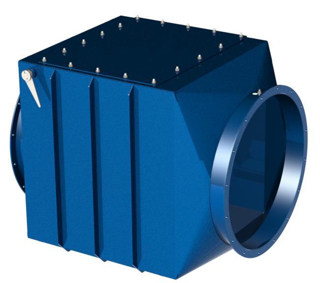
3 Pagenumber: 1 1. PRODUCT DESCRIPTION The non return valves are ATEX certificated protective systems, which prevent a dust explosion propagate through the ductwork into other areas. The non return valve cannot isolate a dust explosion when it propagates through the normal air flow direction. The non return valves are not designed to prevent the transmission of fire or burning powder transported by the normal process flow. The non return valves are built in 2 or 3 mm thick steel, powder coated RAL The ATEX non return valves Formula Air Group comply with the following norms: (EN 16447, ) Figure 1 shows a non return valve. Figure 1: Non Return Valve 1.1 How it works During the normal process, the non return valve s flap remains opened due to the airflow (Figure 2). At deadlock, the valve closes due to the flap s own weight. Figure 2: Non Return Valve in open airflow configuration
4 Pagenumber: 2 When an explosion takes place, the ATEX certified non return valve blocks the expansion of the explosion due to the front spreading pressure along the ductwork (Figure 3). Figure 3: Non Return Valve in closed configuration After an explosion and due to pressure oscillations the valve could re-open. To avoid the re-opening, a safety lock system keeps the valve closed long enough to avoid the propagation of flames during the explosion event, as can be seen in Figure 4. The locking system consists of a spring metal that allows it to bend easily. Therefore, if the flap closes the arm hits the locking system and the top of the locking system will give in. This way, the flap gets locked beneath the top plate of the locking system. Once the explosion is completely over, the lock has to be unblocked manually. The indicator on the outside of the non return valve shows the current position of the flap. Therefore, it can be easily seen if the flap is closed and locked (see Figure 5). Figure 4: Locking system inside the Non Return Valve When the indicator is in this position the flap inside the non return valve is closed and has to be unlocked manually When the indicator is in this position the flap inside the non return valve is open Figure 5: Illustration how the indicator works
5 Pagenumber: Overall dimensions Figure 6: Overall dimensions Type Ø d A B C E F G Mass (mm) (mm) (mm) (mm) (mm) (mm) (mm) (kg) BAR200FF20-ATEX BAR250FF20-ATEX BAR300FF20-ATEX BAR350FF20-ATEX BAR400FF20-ATEX BAR450FF20-ATEX BAR500FF20-ATEX BAR550FF20-ATEX BAR600FF20-ATEX Type Ø H Ø I Ø J Ø K Qty. Flange s1 s2 s3 (mm) (mm) (mm) (mm) holes (mm) (mm) (mm) BAR200FF20-ATEX BAR250FF20-ATEX BAR300FF20-ATEX BAR350FF20-ATEX BAR400FF20-ATEX BAR450FF20-ATEX BAR500FF20-ATEX BAR550FF20-ATEX BAR600FF20-ATEX
 BAR200FF20-ATEX 3 < MIE < 10 BAR250FF20-ATEX 3 < MIE < 10 BAR300FF20-ATEX 3 < MIE < 10 BAR350FF20-ATEX 3 < MIE < 10 BAR400FF20-ATEX 3 < MIE < 10 BAR450FF20-ATEX 3 < MIE < 10")
6 Pagenumber: Technical datasheet Characteristics of dust in relation with the ATEX non return valve: Type Min. Ignition Energy MIE (mj) BAR200FF20-ATEX 3 < MIE < 10 BAR250FF20-ATEX 3 < MIE < 10 BAR300FF20-ATEX 3 < MIE < 10 BAR350FF20-ATEX 3 < MIE < 10 BAR400FF20-ATEX 3 < MIE < 10 BAR450FF20-ATEX 3 < MIE < 10 BAR500FF20-ATEX 3 < MIE < 10 BAR550FF20-ATEX 3 < MIE < 10 BAR600FF20-ATEX 3 < MIE < 10 Zone Push flow situation Considering the normal process flow direction, the situation where the fan is located upstream of the explosion source (Figure 7). Figure 7: Push flow situation

7 Pagenumber: Pull flow situation Considering the normal process flow direction, the situation where the fan is located downstream of the explosion source (Figure 8). Figure 8: Pull flow situation Special conditions for safe use Installation: - The valve should only be exposed to organic or non-metallic dust. - Ambient temperature from -20 C to 60 C. - Dust parameters: K st,max 200 MPa.ms -1, MESG * 2 mm. - DN : Pull and push, straight pipes between the protected vessel and the flap. - DN : Pull flow situation, straight pipes between the protected vessel and the flap and venting on the protective vessel only non-reclosing vent devices. (this excludes e.g. suppression and venting with reclosing vent devices). - The maximum allowable opening angle of the blade is 60 to the vertical. - The maximum flow velocity is: 25 m/s. - Flap position is horizontal. Parameters dependent on the size of the flap: Paramaters of flap (unit): Sizes DN (mm): p red,max (bar) 0,50 p max (bar) design pressure - EN minimal vessel volume (m 3 ) 0,4 0,9 6 minimal installation distance (m) maximal installation distance (m) 7 inclination of flap valve horizontal maximal speed flow (m.s -1 ) 25 max. dust concentration in duct where device will be installed; Without limits
8 Pagenumber: 6 2. INSTALLATION CAUTION! The non return valve installation, connection, start-up and maintenance has to be performed in absence of potentially explosive atmosphere through the process interruption. CAUTION! The installation, connection, start-up and maintenance of the non return valves have to be performed by qualified personnel. Use the right equipment and costumes, and do not work alone. 2.1 Valve installation direction For a right installation, the air flow direction in normal working conditions has to be the same as indicated by the arrows on Figure 9. Air Flow Figure 9: Installation direction regarding to the Air Flow The non return valve needs to be installed horizontally. The inspection panel must always be set upwards, see Figure 10. Figure 10: Installation direction


9 Pagenumber: Connecting the non return valve For the best isolation effectiveness, the non return valve needs to be installed in proximity of the risk zone which it is wanted to be isolated. Step 1: Connect the inlet and outlet to the duct system with the correct fasteners (Figure 11). Use non electrostatic sealing to make it airtight. Sealing tape ATEX Non Return Valve Sealing tape Outlet air duct Figure 11: Installation Step 1 Inlet air duct Step 2: Make sure that the indicator is in the correct position (Figure 12). Make sure the indicator is in this position When the indicator is in this position, the valve is blocked and it will block the air flow Figure 12: Indicator Position
10 Pagenumber: Precautions for a proper use CAUTION! - It is strictly forbidden to open the inspection panel while the air flow is running through the duct. - During maintenance keep the system disconnected and all the electrical equipment turned off. - The valve should not be placed in an environment that could create a vibration in the non return valve. - After the event of an explosion, do not unblock or manipulate the non return valve until the explosion is completely extinguished. Check if the non return valve and its parts are working properly. Clean the valve. If any port got damaged, replace it! CAUTION! Be aware of hot particles remaining inside the valve, even if the explosion is over. While opening the inspection panel, parts can fall off from the inside, damaging the operator or goods. - Every time there is a potentially explosive atmosphere danger, special safety steps must be taken, as the following: o The non return valve is allowed to be used in places where the risk of igniting the explosive atmosphere can t be brought to the minimum tolerable. o Tools or operations which can produce sparks, which can cause gas ignition, or flammable vapors, are not allowed to be used in any procedure that takes place in any area classified as explosion risk. o Avoid dust removal by blowing while cleaning. o The use of free flames near the explosion risk area is strictly forbidden. o The use of electric material that is not marked II of the Directive 99/92/CE is not allowed.
11 Pagenumber: 9 3. MAINTENANCE AND TROUBLESHOOTING CAUTION! The non return valve installation, connection, start-up and maintenance has to be performed in absence of potentially explosive atmosphere through the process interruption. CAUTION! The installation, connection, start-up and maintenance of the non return valves have to be performed by qualified personnel. Use the right equipment and costumes, and do not work alone. CAUTION! Any modifications done by the user on the non return valve are at the users own risk! 3.1 Maintenance Clean and check the performance of the non return valve regularly. Checking is suggested every two months and after any incident that can block or damage the non return valve Cleaning and checking the inside of the non return valve Step 1: Open the inspection panel by unscrewing the M8 nuts (Figure 13). Figure 13: Unscrew the M8 nuts Step 2: Clean the inside of the valve and check the condition of every part. Step 3: Close the inspection door by tightening the M8 nuts. If necessary, renew the sealing tape to make sure it remains airtight (Figure 14). Figure 14: Tightening of the M8 nuts
12 Pagenumber: DISMANTLING AND RECLYING When dismantling a unit, be sure to keep in mind the following important information: CAUTION! Make sure there is no remaining any explosion potential dust of similar before dismantling. As the unit is dismantled, set aside all still functioning parts in order to re-use them on another unit. You should always separate the different materials depending on their type: steel, stainless steel, rubber, foams, etc Recyclable parts must be disposed in the appropriate containers or brought to a local recycling company. The rubbish must be collected in special containers with appropriate labels and disposed in compliance with the nation laws and/or local legislations if force. CAUTION! It is strictly forbidden to dispose toxic wastes in municipal sewerage and drain systems. This concerns all oils, greases, and other toxic materials in liquid or solid form. Figure 15: Recycling the non return valve
13 Pagenumber: ATEX CERTIFICATION EXPLOSIVE ATMOSPHERE DANGER This symbol indicates information concerning the directive ATEX 94/9/CE. Every information attended by this symbol must be executed by highly qualified personnel, competent in safety environments regarding to places characterized by the presence of potentially explosive atmospheres. 5.1 Potentially explosive atmosphere An explosive atmosphere for the purpose of Directive 94/9/EC is defined as a mixture with air, under atmospheric condition, of flammable substances in the form of gases, vapors, mists or dusts in which, after ignition has occurred, combustion spreads to the entire unburned mixture. A potentially explosive atmosphere is an atmosphere which could become explosive due to local and operational conditions Dangerous areas classification In carrying out the obligations laid down in Directive 99/92/EC, hazardous places are classified in terms of zones on the basis of the frequency and duration of the occurrence of an explosive atmosphere. Zone 0: A place in which an explosive atmosphere consisting of a mixture with air of flammable substances in the form of gas, vapor or mist is present continuously or for long periods for frequently. Zone 1: A place in which an explosive atmosphere consisting of a mixture with air of flammable substances in the form of gas, vapor or mist is likely to occur in normal operation occasionally. Zone 2: A place in which an explosive atmosphere consisting of a mixture with air of flammable substances in the form of gas, vapor or mist is not likely to occur in normal operation but, if it does occur, will persist for a short period only. Zone 20: A place in which an explosive atmosphere in the form of a cloud of combustible dust in air is present continuously, or for long periods or frequently. Zone 21: A place in which an explosive atmosphere in the form of a cloud of combustible dust in air is likely to occur in normal operation occasionally. Zone 22: A place in which an explosive atmosphere in the form of a cloud of combustible dust in air is not likely to occur in normal operation but, if it does occur, will persist for a short period only Protective system s selection criteria The ATEX 94/9/EC Directive classifies the protection system (in this case the non return valve) into 3 categories, with different protection levels, guaranteed to the related protection. Protection Level Mine Category Gas Category Plant Dust Category Very High M1 1G (zone 0) 1D (zone 20) High M2 2G (zone 1) 2D (zone 21) Normal - 3G (zone 2) 3D (zone 22)
14 Pagenumber: ATEX code description 5.3 Product identification The identification of Formula Air Group as manufacturer of the non return valve is due to the conformity with the current legislation by means of the following: - Declaration of conformity according to Directive ATEX 94/9/CE - Maintenance manual - Marking plate ATEX of outlet explosion device (Figure 16).
15 Pagenumber: 13 Bosscheweg SX Beek en Donk The Netherlands Product: Non Return Valve Type: BAR FF20-ATEX Serial Number: Production year: 20 P Red, max 0.5 bar P max 1 bar V max 25 m/s T amb -20 C to +60 C Minimal vessel volume m 3 Inclination of flap valve Horizontal Max. dust concentration Without limits ATEX certificate: FTZÚ 14 ATEX 0111X Numbers of standard: EN16447 II D St 1 II 1/2D TX Please refer to user manual before installation Figure 16: Name label used for every ATEX Non Return Valve Explanation of the label (Figure 16): 1) Name and address of the manufacturer 2) CE marking 3) Designation of series of type 4) Serial number 5) Year of construction 6) Explosion resistance pressure or explosion shock resistance pressure for the flap valve** 7) Maximal airspeed 8) Ambient temperature range 9) The volume of the Non Return Valve 10) Positioning of the Non Return Valve 11) Maximal dust concentration in duct at install location 12) The certification reference 13) The numbers of standard that are used 14) For equipment-group II, G (Gas) and/or D (Dust)* * Acconding to II ATEX 94/9/EC minimum info (some other manuals have more info) ** Acconding to EN
16 Pagenumber: USEFUL INFO RELATED TO THIS MANUAL This manual is compiled in accordance with the Directive ATEX 94/9/CE. This manual cannot be reproduced, even partially, without prior written consent by Formula Air Group. Every step of the non return valve all along its life cycle has been deeply analyzed by Formula Air Group in the expected area during the design, construction and manual creation. However, it is understood that nothing can replace the experience, training and good sense of those professionals who work with the device. Ignoring the cautions and warning from the present manual, using improperly parts or the whole device supplied, using not authorized spare parts, manipulation the device by non qualified personnel, violation of any safety norm regarding design, construction and use expected by the supply, release Formula Air Group from every responsibility in case of damages to people or properties. Formula Air Group does not take any responsibility for the non observance of the user with regard to the preventive safety measures presented in this manual. Warranty: Regarding to the device s warranty, see the sales general condition in the contractual center. NOTE : All drawings and references contained within this manual are non-contractual and are subject to change without prior notice at the discretion of the Formula Air Group and its partners. Created on , by Lars Gevers. Formula-Air Netherlands
TP1 and TP2 Temporary Cone Shaped Strainers
 1698051/2 IM-P169-07 ST Issue 2 TP1 and TP2 Temporary Cone Shaped Strainers Installation and Maintenance Instructions TP1 1. Safety information 2. General product information 3. Installation and commissioning
NON-RETURN FLAP VALVE MODEL NOREX (unidirectional valve)
") NON-RETURN FLAP VALVE MODEL NOREX 800-1000 (unidirectional valve) Installation, maintenance and user manual for DN800-DN1000 Norex valves Manual number: MAN_NOREX_800-1000_SI_En_13_03 Manual compiled in
NON-RETURN FLAP VALVE MODEL NOREX 800-1000 (unidirectional valve) Installation, maintenance and user manual for DN800-DN1000 Norex valves Manual number: MAN_NOREX_800-1000_SI_En_13_03 Manual compiled in
PV4 and PV6 Piston Valves
 1181250/1 IM-P118-05 ST Issue 1 PV4 and PV6 Piston Valves Installation and Maintenance Instructions 1. Safety information 2. General product information 3. Installation 4. Commissioning 5. Operation 6.
CAST IRON SAFETY VALVE TYPE 6301
 CHARACTERISTICS The 6301 safety valve is dedicated to protect the equipment from potential overpressure. This is an automatic device that closes when the pressure conditions are back to normal. It is a
KBV21i and KBV40i Key Operated Boiler Blowdown Valves Installation and Maintenance Instructions
 4059051/3 IM-P405-48 EMM Issue 3 KBV21i and KBV40i Key Operated Boiler Blowdown Valves Installation and Maintenance Instructions 1. Safety information 2. General product information 3. Installation 4.
SNRQ ATEX non return valve. Maintenance manual
 SNRQ ATEX non return valve Maintenance manual 1 Table of contents 1. Norms and general information.....2 1.1. Document identification "Maintenance Manual".... 2 1.2. Document purpose. 3 1.3. General instructions
EXPLOSIVE ATMOSPHERES - CLASSIFICATION OF HAZARDOUS AREAS (ZONING) AND SELECTION OF EQUIPMENT
 AND SELECTION OF EQUIPMENT") EXPLOSIVE ATMOSPHERES - CLASSIFICATION OF HAZARDOUS AREAS (ZONING) AND SELECTION OF EQUIPMENT OVERVIEW ASSESSING THE RISK RELATIONSHIP BETWEEN FIRES AND EXPLOSIONS CLASSIFYING HAZARDOUS AREAS INTO ZONES
EXPLOSIVE ATMOSPHERES - CLASSIFICATION OF HAZARDOUS AREAS (ZONING) AND SELECTION OF EQUIPMENT OVERVIEW ASSESSING THE RISK RELATIONSHIP BETWEEN FIRES AND EXPLOSIONS CLASSIFYING HAZARDOUS AREAS INTO ZONES
BT6HC Hygienic Sanitary Balanced Pressure Steam Trap for High Capacity and CIP/SIP Applications
 1800350/6 IM-P180-12 ST Issue 6 BT6HC Hygienic Sanitary Balanced Pressure Steam Trap for High Capacity and CIP/SIP Applications Installation and Maintenance Instructions 1. Safety information 2. General
DCV10 Stainless Steel Disc Check Valve for use with Condensate Pumps
 6018050/1 IM-P601-33 ST Issue 1 DCV10 Stainless Steel Disc Check Valve for use with Condensate Pumps Installation and Maintenance Instructions 1. Safety information 2. General product information 3. Installation
Thermocirc Installation and Maintenance Instructions
 1570072/2 IM-P157-36 ST Issue 2 Thermocirc Installation and Maintenance Instructions 1 General safety information 2 General product information 3 Installation 4 Commissioning 5 Operation 6 Maintenance
KBV21i and KBV40i Air Actuated Boiler Blowdown Valves
 4059051/1 IM-P405-48 AB Issue 1 KBV21i and KBV40i Air Actuated Boiler Blowdown Valves Installation and Maintenance Instructions 1. Safety information 2. General product information 3. Installation 4. Commissioning
Differential Pressure Regulator Type Type 45-6 (0.1 to 1 bar, DN 15) Mounting and Operating Instructions EB 3226 EN
 Mounting and Operating Instructions EB 3226 EN") Differential Pressure Regulator Type 45-6 Type 45-6 (0.1 to 1 bar, DN 15) Mounting and Operating Instructions EB 3226 EN Edition March 2008 Contents Contents Page 1 Design and principle of operation...................
Differential Pressure Regulator Type 45-6 Type 45-6 (0.1 to 1 bar, DN 15) Mounting and Operating Instructions EB 3226 EN Edition March 2008 Contents Contents Page 1 Design and principle of operation...................
MF2M Monnier Miniature Compressed Air Filter
 5040050 / 2 IM-P504-02 CH Issue 2 MF2M Monnier Miniature Compressed Air Filter Installation and Maintenance Instructions 1. Safety information 2. General product information 3. Installation and commissioning
DF1 and DF2 Diffusers
 1550650/4 IM-P155-07 ST Issue 4 and Diffusers Installation and Maintenance Instructions 1. Safety information 2. General product information 3. Installation 4. Commissioning 5. Operation 6. Maintenance
Dri-Line Mk2 Spirax-Monnier Compressed Air Drain Trap
 0509950/2 IM-P050-21 CH Issue 2 Dri-Line Mk2 Spirax-Monnier Compressed Air Drain Trap Installation and Maintenance Instructions 1. Safety information 2. General product information 3. Installation and
VALFONTA INSTRUCTIONS: OPERATION AND INSTALLATION PRESSURE REDUCING VALVE MODEL PRV44
 INSTRUCTIONS: OPERATION AND INSTALLATION PRESSURE REDUCING VALVE MODEL PRV44 Pressure Reducing Valve PRV44 - Operation and Installation - 1 - manual PRV44-16-ENG JULY 2016 INDEX PAGE 1 IDENTIFICATION PLATE
FV Flash Vessel Installation and Maintenance Instructions
 4041050/5 IM-P404-10 EMM Issue 5 FV Flash Vessel Installation and Maintenance Instructions 1. Safety information 2. Specific product safety information 3. Product information 4. Installation 5. Commissioning
6301 TYPE CAST IRON SAFETY VALVES
 Pressure (bar) 6301 TYPE CAST IRON SAFETY VALVES FEATURES The 6301 type safety valve is a device designed to protect installations against possible overpressure. It operates automatically and closes when
Manual Actuated Boiler Blowdown Valves
 Manual Actuated Boiler Blowdown Valves Installation and Maintenance Instructions 1. Safety information 2. General product information 3. Installation 4. Operation 5. Maintenance 6. Spare parts p.1 1. Safety
DCV1, DCV3 and DCV3LT Disc Check Valves Installation and Maintenance Instructions
 1340050/7 IM-P134-07 CMGT Issue 7 DCV1, DCV3 and DCV3LT Disc Check Valves Installation and Maintenance Instructions 1. Safety information 2. General product information 3. Installation 4. Commissioning
CP10 Sensor Installation and Maintenance Instructions
 4030150/9 IM-P403-26 EMM Issue 9 CP10 Sensor Installation and Maintenance Instructions 1. Safety information 2. General product information 3. Installation 4. Maintenance 5. Spare parts Copyright 2017
Mounting and Operating Instructions EB 3007 EN. Self-operated Pressure Regulators. Differential Pressure Regulators (opening) Type Type 42-25
 Type Type 42-25") Self-operated Pressure Regulators Differential Pressure Regulators (opening) Type 42-20 Type 42-25 Type 42-20 Differential Pressure Regulator Type 42-25 Differential Pressure Regulator Mounting and Operating
Self-operated Pressure Regulators Differential Pressure Regulators (opening) Type 42-20 Type 42-25 Type 42-20 Differential Pressure Regulator Type 42-25 Differential Pressure Regulator Mounting and Operating
IX1 Spirax-Monnier International Compressed Air Filter Installation and Maintenance Instructions
 0575050/2 IM-P057-04 CH Issue 2 IX1 Spirax-Monnier International Compressed Air Filter Installation and Maintenance Instructions 1 Safety information 2 General product information 3 Installation and commissioning
Spiratec ST14, ST16 and ST17 Sensor Chambers and sensors
 0862050/1 IM-P086-18 MI Issue 1 Spiratec ST14, ST16 and ST17 Sensor Chambers and sensors Installation and Maintenance Instructions 1. Safety Information 2. General product information 3. Installation 4.
TSS21 Sealed Thermostatic Steam Tracer Trap
 1255050/4 IM-P125-10 ST Issue 4 TSS21 Sealed Thermostatic Steam Tracer Trap Installation and Maintenance Instructions 1. Safety information 2. General product information 3. Installation 4. Commissioning
Dri-Line Mk3 Monnier Compressed Air Drain Trap
 5044050/2 IM-P504-24 CH Issue 2 Dri-Line Mk3 Monnier Compressed Air Drain Trap Installation and Maintenance Instructions 1. Safety information 2. General product information 3. Installation and Operation
VS18/26 with PROFINET and EtherNet/IP Interface. ATEX Installation Instructions
 VS18/26 with PROFINET and EtherNet/IP Interface ATEX Installation Instructions INDEX 1. INTENDED USAGE 3 2. OPERATING MANUAL ATEX 4 2.1 General conditions 4 2.2 Installation 5 2.3 Operating 5 2.4 Failures
MST21 Stainless Steel Balanced Pressure Thermostatic Steam Trap
 1250650/6 IM-P125-07 ST Issue 6 MST21 Stainless Steel Balanced Pressure Thermostatic Steam Trap Installation and Maintenance Instructions 1. Safety information 2. General product information 3. Installation
Installation, commissioning and servicing instructions
 488.03 www.reece.com.au Pressure reducing s Installation, commissioning and servicing instructions Function Pressure reducing s are installed in residential water systems to reduce and stabilise inlet
WHEATLEY Series 500 Swing Check Valve
 Document Number: TC003001-13 Revision: 02 WHEATLEY Series 500 Swing Check Valve Installation, Operation, and Maintenance Manual TABLE OF CONTENTS BILL OF MATERIALS...3 SCOPE...5 INSTALLATION AND OPERATION
Operating Instructions
 Operating Instructions Light-metal Ex d enclosures / flameproof enclosure > 8265/0 Empty enclosure > 8265/4 Control panel, integrated in Ex e enclosure > 8265/5 Control panel Table of Contents 1 Table
IS YOUR FLAP VALVE IN COMPLIANCE WITH NFPA ?
 IEP Technologies 417-1 South Street, Marlborough, MA, 01752 ph 855.793.8407 fax 508.485.3115 www.ieptechnologies.com IS YOUR FLAP VALVE IN COMPLIANCE WITH NFPA 69-2014? Introduction Dust explosions can
Instruction Manual. Alfa Laval SB Membrane Sample Valve ESE02963-EN Original manual
 Instruction Manual Alfa Laval SB Membrane Sample Valve ESE02963-EN2 2016-02 Original manual Table of contents The information herein is correct at the time of issue but may be subject to change without
S1, S2, S3, S5, S6, S7, S8, S12 and S13 Separators Installation and Maintenance Instructions
 PREVIOUS REFERENCE NO. IMP02355 0231150/13 IMF0501ENISS2 CMGT S1, S2, S3, S5, S6, S7, S8, S12 and S13 Separators Installation and Maintenance Instructions 1. Safety information 2. General product information
DCV6 Disc Check Valve
 1342050/6 IM-P134-22 ST Issue 6 DCV6 Disc Check Valve Installation and Maintenance Instructions Printed IM-P134-22 in the UK ST Issue 6 Copyright 20101 Safe operation of this product can only be guaranteed
VALFONTA INSTRUCTIONS: OPERATION AND INSTALLATION PRESSURE REDUCING VALVE MODEL M2
 INSTRUCTIONS: OPERATION AND INSTALLATION PRESSURE REDUCING VALVE MODEL M2 Pressure Reducing Valve M2 - Operation and Installation - 1 - M2-13E-ENG FEBRUARY 2017 ÍNDICE PÁGINA 1 IDENTIFICATION PLATE LEGEND
DK46 - DK800 Supplementary instructions
 DK46 - DK800 Supplementary instructions Variable area flowmeter Device category II2G with electrical internals Additional Ex manual KROHNE CONTENTS DK46 - DK800 1 Safety instructions 3 1.1 General... 3
Flow controller Type ED/CCB311 Instruction manual
 Flow measurement Flow controller Type ED/CCB311 1. GENERAL DESCRIPTION page 4 2. DETAILED DESCRIPTION page 4 3. PIPE - EXPLOITATION page 5 4. PREVENTIVE MAINTENANCE page 5 5. REPLACEMENT OF THE CONTACT
G type DUCTED EXHAUST SAFETY VALVE 2871 AND 288X SERIES. Model/Ref:
 Model/Ref: 28713 www.lauridsenindustri.com CHARACTERISTICS The G type safety valves are dedicated to protect the equipment from potential overpressure. They are automatic and close when the pressure conditions
WHEATLEY Series 822/820 Swing Check Valve
 Document Number: TC003001-12 Revision: 02 WHEATLEY Series 822/820 Swing Check Valve Installation, Operation, and Maintenance Manual TABLE OF CONTENTS BILL OF MATERIALS...3 SCOPE...4 INSTALLATION AND OPERATION
Operating Instructions. Ball valve fitting according to ZB For pressure transmitter VEGABAR 82. Document ID: 50027
 Operating Instructions Ball valve fitting according to ZB 2553 For pressure transmitter VEGABAR 82 Document ID: 50027 Contents Contents 1 About this document 1.1 Function... 3 1.2 Target group... 3 1.3
1.8 INDUSTRIAL PROCESS WEIGHING IN HAZARDOUS AREAS
 1.8 INDUSTRIAL PROCESS WEIGHING IN HAZARDOUS AREAS EXPLOSION PROTECTION In addition to the type approval and certification of industrial weighing systems concerned with accuracy, equipment that is also
Regulator for 2 MPa ARX 20. How to Order. Bracket. Pressure gauge. Port size 1/8 1/4. Panel nut
 Regulator for 2 MPa RX 2 How to Order RX2 1 Regulator 1 Regulating pressure.5 to.85mpa {.51 to 8.7kgf/cm²}.5 to.3mpa {.51 to 3.1kgf/cm²} Thread type Nil N F Rc(PT) NPT (PF) Port size 1 2 ccessories/options
Instruction Manual. Alfa Laval SB Pressure Exhaust Valve ESE02965-EN Original manual
 Instruction Manual Alfa Laval SB Pressure Exhaust Valve ESE02965-EN1 2015-10 Original manual Table of contents The information herein is correct at the time of issue but may be subject to change without
SA121, SA122, SA123, SA128 and SA1219 Self-acting Temperature Control Systems (Knob Adjustment)
") 3810050/5 IM-P381-01 CH Issue 5 SA121, SA122, SA123, SA128 and SA1219 Self-acting Temperature Control Systems (Knob Adjustment) Installation and Maintenance Instructions 1. Safety information 2. Use 3.
3810050/5 IM-P381-01 CH Issue 5 SA121, SA122, SA123, SA128 and SA1219 Self-acting Temperature Control Systems (Knob Adjustment) Installation and Maintenance Instructions 1. Safety information 2. Use 3.
Mounting and Operating Instructions EB 2558 EN. Self-operated Pressure Regulators. Type Pressure Build-up Regulator
 Self-operated Pressure Regulators Type 2357-31 Pressure Build-up Regulator with safety function and integrated excess pressure valve Type 2357-31 with non-return unit at port C Ports A and B with soldering
TA10A and TA10P Steam Tracing Temperature Control Valves Installation and Maintenance Instructions
 3500032/2 IM-P350-02 CH Issue 2 TA10A and TA10P Steam Tracing Temperature Control Valves Installation and Maintenance Instructions 1. Safety information 2. General product information 3. Installation 4.
S1, S2, S3, S5, S6, S7, S8, S12 and S13 Separators
 0231150/8 IM-P023-55 ST Issue 8 S1, S2, S3, S5, S6, S7, S8, S12 and S13 Separators Installation and Maintenance Instructions 1. Safety information 2. General product information 3. Installation 4. Commissioning
Incorrect installation, adjustment, or misuse of this burner could result severe personal injury, or substantial property damage.
 Operating instructions GB VD Burners Incorrect installation, adjustment, or misuse of this burner could result severe personal injury, or substantial property damage. To the Equipment Owner: Please read
Measurement accessories METPOINT OCV for the measurement in systems up to 40 bar
 EN - english Instructions for installation and operation Measurement accessories METPOINT OCV for the measurement in systems up to 40 bar Dear customer, Thank you for deciding in favour of the METPOINT
TD45 Thermodynamic Steam Trap Installation and Maintenance Instructions
 0685255/1 IM-P068-47 ST Issue 1 TD45 Thermodynamic Steam Trap Installation and Maintenance Instructions 1 General safety information 2 General product information 3 Installation 4 Commissioning 5 Operation
Explosion Isolation. No matter what happens - nothing happens. / RICO Slide Valve RSV-D, RSV-G, RSV-P
 Explosion Isolation. No matter what happens - nothing happens. / Ventex ESI-E/-D, ESI-C, ESI-P RICO Slide Valve RSV-D, RSV-G, RSV-P REDEX Flap REDEX Slide Confidence through safety: rico Sicherheitstechnik
Instruction Manual Contact Pressure Vacuum Gauge
 MS10 Instruction Manual Contact Pressure Vacuum Gauge Table of Contents 1. Safety Instructions 2. Intended Applications 3. Product Description and Functions 4. Installation 5. Commissioning 6. Maintenance
1. Preface Important Safety Notes Brief Product Information Product Working Principle Installation Guidelines...
 Table of Contents 1. Preface...1 2. Important Safety Notes...1 3. Brief Product Information...3 4. Product Working Principle...5 5. Installation Guidelines...6 6. Startup and Commissioning...8 7. Maintenance
CVS10 Sanitary Check Valves
 0299050/4 IM-P029-11 ST Issue 4 CVS10 Sanitary Check Valves Installation and Maintenance Instructions 1. Safety information CVS10 with soft seat 2. General product information 3. Operation 4. Installation
SA121, SA122, SA123, SA128 and SA1219 Self-acting Temperature Control Systems (Dial Adjustment)
") 3820050/4 IM-P382-01 CH Issue 4 SA121, SA122, SA123, SA128 and SA1219 Self-acting Temperature Control Systems (Dial Adjustment) Installation and Maintenance Instructions 1. Safety information 2. Use 3.
3820050/4 IM-P382-01 CH Issue 4 SA121, SA122, SA123, SA128 and SA1219 Self-acting Temperature Control Systems (Dial Adjustment) Installation and Maintenance Instructions 1. Safety information 2. Use 3.
This document is meant purely as a documentation tool and the institutions do not assume any liability for its contents
 1999L0092 EN 27.06.2007 001.001 1 This document is meant purely as a documentation tool and the institutions do not assume any liability for its contents B DIRECTIVE 1999/92/EC OF THE EUROPEAN PARLIAMENT
DIAPHRAGM PUMP MODEL PDM 1-175
 INSTRUCTION MANUAL DIAPHRAGM PUMP MODEL PDM 1-175 Manual : 0704 573.034.112 Date : 18/04/07 - Supersede : 17/06/02 - Modif. : + ATEX KREMLIN REXSON - 150, avenue de Stalingrad - 93245 STAINS Cedex - FRANCE
INSTRUCTION MANUAL Pressure Relief Device LPT
 INSTRUCTION MANUAL Pressure Relief Device LPT 5COV475800 LPT REV00 CONTENT: 1 SAFETY 1.1 Safety instructions 2 1.2 Specified applications 2 1.3 Safety notes on the equipment operation 2 2 PRESSURE RELIEF
Installation & Operation Manual Proven Quality since 1892
 Content 1. ERIKS operating companies 2. Product description 3. Requirements for maintenance staff 4. Transport and storage 5. Function 6. Application 7. Installation 8. Maintenance 9. Service and repair
MANUAL. Verkstadsvagen 2, SE SKELLEFTEA, Sweden Tel , Fax P17W45_MPREX_F_EN
 MANUAL Verkstadsvagen 2, SE 931 61 SKELLEFTEA, Sweden Tel. +46 910-361 80, Fax. +46 910-130 22 www.fumex.com info@fumex.se P17W45_MPREX_F_EN Contents Important information 3 Applications 3 Technical data
Instruction Manual. AlfaLavalSBAntiVacuumValve ESE02960-EN Original manual
 Instruction Manual AlfaLavalSBAntiVacuumValve ESE02960-EN3 2017-11 Original manual Table of contents The information herein is correct at the time of issue but may be subject to change without prior notice
Type Operating Instructions. 2/2-way solenoid valve 2/2-Wege Magnetventil Electrovanne 2/2 voies.
 2/2-way solenoid valve 2/2-Wege Magnetventil Electrovanne 2/2 voies We reserve the right to make technical changes without notice. Technische Änderungen vorbehalten. Sous réserve de modifications techniques.
QUANTIFYING THE TOLERABILITY OF POTENTIAL IGNITION SOURCES FROM UNCERTIFIED MECHANICAL EQUIPMENT INSTALLED IN HAZARDOUS AREAS
 QUANTIFYING THE TOLERABILITY OF POTENTIAL IGNITION SOURCES FROM UNCERTIFIED MECHANICAL EQUIPMENT INSTALLED IN HAZARDOUS AREAS Steve Sherwen Senior Consultant, ABB Engineering Services, Daresbury Park,
M45 ISO Ball Valve DN25 to 150 Installation and Maintenance Instructions
 BAC 13310 IM-P133-42 ST Issue 2 M45 ISO Ball Valve DN25 to 150 Installation and Maintenance Instructions 1. General safety information 2. General product information 3. Installation 4. Commissioning 5.
BSA6T and BSA64T Stainless Steel Bellows Sealed Stop Valves Installation and Maintenance Instructions
 1843950/3 IM-P184-03 ST Issue 3 BSA6T and BSA64T Stainless Steel Bellows Sealed Stop Valves Installation and Maintenance Instructions 1. General safety information 2. General product information 3. Installation
Steam Trap BK 15 (DN40, DN 50) Original Installation Instructions English
 Original Installation Instructions English") Steam Trap BK 15 (DN40, DN 50) EN English Original Installation Instructions 810682-03 1 Contents Page Important Notes Usage for the intended purpose... 4 Safety note... 4 Danger... 4 Attention... 4 Application
Steam Trap BK 15 (DN40, DN 50) EN English Original Installation Instructions 810682-03 1 Contents Page Important Notes Usage for the intended purpose... 4 Safety note... 4 Danger... 4 Attention... 4 Application
WHEATLEY WHEATLEY SERIES 500 SWING CHECK VALVE. Installation, Operation and Maintenance Manual
 WHEATLEY SERIES 500 SWING CHECK VALVE STANDARD INTEGRAL SEAT & OPTIONAL REMOVABLE SEAT 2" FP - 6" FP 150# - 1500# 8" FP - 12" FP 150# - 900# API 6D and B16.34 2" FP - 4" FP 5000# DRILLING PRODUCTION VALVE
Pilot Check Valve: Metal Body Type
 INFORMATION Pilot Check Valve: Metal Body Type The use of a metal body improves strength and environmental resistance. Temporary intermediate stops are possible. *1 *1 Precise intermediate stops are not
SA Control Valve types: BM, BMF, BX, SB, NS, KA, KB, KC (Normally open) BMRA, BMFRA, BXRA, SBRA, NSRA, KX, KY (Normally closed)
 BMRA, BMFRA, BXRA, SBRA, NSRA, KX, KY (Normally closed)") 0366055/7 IM-S21-01 CH Issue 7 SA Control Valve types: BM, BMF, BX, SB, NS, KA, KB, KC (Normally open) BMRA, BMFRA, BXRA, SBRA, NSRA, KX, KY (Normally closed) Installation and Maintenance Instructions
0366055/7 IM-S21-01 CH Issue 7 SA Control Valve types: BM, BMF, BX, SB, NS, KA, KB, KC (Normally open) BMRA, BMFRA, BXRA, SBRA, NSRA, KX, KY (Normally closed) Installation and Maintenance Instructions
Fig 12, Fig 14HP, Fig 16, Fig 16HP and Fig 16L Strainers
 16355/11 IM-S6-17 ST Issue 11 Fig 12, Fig 14HP, Fig 16, Fig 16HP and Fig 16L Strainers Installation and Maintenance Instructions 1. Safety information 2. General product information 3. Installation 4.
THE MF-400 SERIES. Operating and Service Manual. Series includes all variants of MF-400/401
 THE MF-400 SERIES Operating and Service Manual Series includes all variants of MF-400/401 Issue A October 2013 1 TABLE OF CONTENTS 1. Description... 3 2. Installation... 3 3. Operation... 4 4. Special
Type BBS-03, BBS-05, BBS-06, BBS-25
 Type BBS-03, BBS-05, BBS-06, BBS-25 Sterile connection elements Sterile Verbindungselemente Raccords union stériles Operating Instructions Bedienungsanleitung Manuel d utilisation 1. THE OPERATING INSTRUCTIONS
A guide to Part 10 of the
 OCCUPATIONAL HEALTH AND SAFETY DIVISION Welding, Cutting, Burning and Soldering A guide to Part 10 of the Occupational Safety General Regulations October 2007 A GUIDE TO PART 10 WELDING, CUTTING, BURNING
Serie 06-M6. Swing wafer check valve. made in. Application fields. Check valves E U R O P E WATER CONDITIONING INDUSTRY
 Swing wafer check valve BRANDONI made in E U R O P E Application fields WATER CONDITIONING INDUSTRY HEATING 38 www.brandoni.it The valves in series 06 are swing wafer check valves, manufactured in accordance
CA44, CA44S, CA46 and CA46S Air and Gas Traps
 1484450/3 IM-P148-37 ST Issue 3 CA44, CA44S, CA46 and CA46S Air and Gas Traps Installation and Maintenance Instructions 1. Safety information 2. General product information 3. Installation 4. Commissioning
ATS430 turbidity sensor Retractable insertion assembly
 A MEASUREMENT & ANALYTICS INSTRUCTION ATS430 turbidity sensor Retractable insertion assembly Measurement made easy 1 Introduction This publication details installation procedures for the retractable insertion
MFP14-PPU (Vented) Automatic Packaged Pump Units
 Automatic Packaged Pump Units") 681060/2 IM-P681-02 ST Issue 2 MFP14-PPU (ented) Automatic Packaged Pump Units Installation and Maintenance Instructions 1. Safety information 2. General product information 3. Single MFP14 - PPU installation
681060/2 IM-P681-02 ST Issue 2 MFP14-PPU (ented) Automatic Packaged Pump Units Installation and Maintenance Instructions 1. Safety information 2. General product information 3. Single MFP14 - PPU installation
Booster Regulator/Air Tank
 Booster Regulator/Air Tank Increase factory air pressure by up to 4 times! Air-only operation requires no power supply, reduces heat generation, and Boost pressure allows easy installation. NEW Renewed
Siphon vessel / Priming aid
 Manufacturer: sera GmbH sera-straße 1 34376 Immenhausen Germany Tel.: +49 5673 999-00 Fax: +49 5673 999-01 info@sera-web.com Keep the operating manual for future use! Record the exact type and serial number
USM21 Sealed Bimetallic Steam Trap for use with Pipeline Connectors Installation and Maintenance Instructions
 6250250/1 IM-P625-03 ST Issue 1 USM21 Sealed Bimetallic Steam Trap for use with Pipeline Connectors Installation and Maintenance Instructions 1. General safety information 2. General product information
Declaration of Conformity as per Directive 97/23/EC
 Declaration of Conformity as per Directive 97/23/EC The manufacturer declares that:, 47906 Kempen, Germany Multi-way diverting valves Series 29a and Series 29b, with packing with lever 1. The valves are
Operating and maintenance manual Filter and reducing station Series / 1.0
 Operating and maintenance manual Filter and reducing station Series 961 04.2017 / 1.0 Original instructions ARCA Regler GmbH. All rights reserved. Cover picture background: Freepik.com ARCA Regler GmbH
Instruction Manual. CG16K Barometrically Compensated Capsule Dial Gauge. CG16K Capsule Dial Gauge, 0 to 25 mbar
 Instruction Manual D356-10-880 Issue G Original CG16K Barometrically Compensated Capsule Dial Gauge Description CG16K Capsule Dial Gauge, 0 to 1040 mbar CG16K Capsule Dial Gauge, 0 to 125 mbar CG16K Capsule
INDUSTRIAS IBAIONDO, HYDROPNEUMATIC TANKS
 IBAIONDO, HYDROPNEUMATIC TANKS IBAIONDO, INTRODUCTION Hydropneumatic tanks are designed to be used in potable water supply installations as a part of the pressure booster set in order to ensure the adequate
M33F ISO, M33S ISO and M33V ISO Ball Valves Installation and Maintenance Instructions
 BAC13365 IM-P133-65 CMGT Issue 2 M33F ISO, M33S ISO and M33V ISO Ball Valves Installation and Maintenance Instructions 1. Safety information 2. General product information 3. Installation 4. Commissioning
Fig 1, Fig 12, Fig 13, Fig 14HP, Fig 16, Fig 16HP and Fig 16L Strainers
 16355/8 IM-S6-17 ST Issue 8 Fig 1, Fig 12, Fig 13, Fig 14HP, Fig 16, Fig 16HP and Fig 16L Strainers Installation and Maintenance Instructions 1. Safety information 2. General product information 3. Installation
Installation, operation & maintenance manual - original version
 Installation, operation & maintenance manual - original version AVK gate valves for water and wastewater Series 01, 02, 06, 12, 15, 18, 20, 26, 32, 33, 36, 38, 50, 55 and 636 COPYRIGHT AVK GROUP A/S 2018
ATEX installation and service instruction
 ATEX installation and service instruction 2014/34/EU for Cat 1 Zone 20 Knife gate valves series XV, MV, MP, HG (HP), HL, HX, WB (WB11, 12, 14), RKO, JTV, D2G ATEX installation and service instruction 2014/34/EU
Operating Instructions in compliance with Pressure Equipment Directive 2014/68/EU. FAS Brass Check Valve RDL
 Operating Instructions in compliance with Pressure Equipment Directive 2014/68/EU FAS Brass Check Valve RDL Please read these operating instructions carefully to ensure a safe operation and keep the same
User Manual. Quantos Automated Dosing Liquid Module
 User Manual Liquid Module 1 Safety Information 1.1 Definition of warnings and symbols Signal Words WARNING for a hazardous situation with medium risk, possibly resulting in severe injuries or death if
II 2G EEx ia IIC T6. Ignition protection class
 ATEX General information According to 94/9/EC, a device that is to be used in an environment at risk of explosion may only be brought into the market if it satisfies the standards specified in the norm.
AE50S Automatic Air and Gas Vent for Liquid Systems Installation and Maintenance Instructions
 0176050/3 IM-P017-11 ST Issue 3 AE50S Automatic Air and Gas Vent for Liquid Systems Installation and Maintenance Instructions 1 General safety information 2 General product information 3 Installation 4
for the of and the EM55-1
 Operating Manua al for the Tapping Points of the EM55-1/EM55-2/EM55-3/ /EM55-4 series and the EE55-1/EE55-2/EE55-3/EE55-4 series EM55-1 Contents Contents... 2 1. Introduction... 3 1.1 General... 3 1.2
U S E R M A N U A L CAUTION. SAVE THESE INSTRUCTIONS Federal (USA) law restricts this device to sale by or on the order of a physician.
 law restricts this device to sale by or on the order of a physician.") U S E R M A N U A L 1600 SERIES OXYGEN REGULATOR 168715G (Shown) SAVE THESE INSTRUCTIONS Federal (USA) law restricts this device to sale by or on the order of a physician. 300 Held Drive Tel: (+001) 610-262-6090
U S E R M A N U A L 1600 SERIES OXYGEN REGULATOR 168715G (Shown) SAVE THESE INSTRUCTIONS Federal (USA) law restricts this device to sale by or on the order of a physician. 300 Held Drive Tel: (+001) 610-262-6090
MPC1M, MPC2M and MPC2AM Monnier High Efficiency Compressed Air Filter / Regulators
 5043150 /2 IM-P504-08 CH Issue 2 MPC1M, MPC2M and MPC2AM Monnier High Efficiency Compressed Air Filter / Regulators Installation and Maintenance Instructions 1. Safety information 2. General product information
Technical Data. General specifications Switching element function Rated operating distance s n 2 mm
 0102 Model Number Features 2 mm flush Usable up to SIL 2 acc. to IEC 61508 Accessories EXG-12 Quick mounting bracket with dead stop BF 12 Mounting flange, 12 mm Technical Data specifications Switching
Pre-filter for Brushless Blower Instruction Manual
 Pre-filter for Brushless Blower 781-70-702 Instruction Manual Minebea Co., Ltd. Industrial Machinery Business Unit 251-8531 1-1-1 Katase,Fujisawa,kanagawa Contact Us Industrial Machinery Product Sales
AVM7 Stainless Steel Thermostatic Air Vent
 1231850/4 IM-P123-23 ST Issue 4 AVM7 Stainless Steel Thermostatic Air Vent Installation and Maintenance Instructions 1. Safety information 2. General product information 3. Installation 4. Commissioning
3/8" Dr. Air Butterfly Impact Wrench
 8192106 3/8" Dr. Air Butterfly Impact Wrench Owner s Manual Read and understand all instructions before use. Retain this manual for future reference. Specifications Construction: Polished aluminum and