MEGR-1627 Instruction Manual
|
|
|
- Merryl Washington
- 5 years ago
- Views:
Transcription


1 MEGR-1627 HIGH FLOW GAS REGULATOR Instruction Manual- Look Inside For: Description Installation Remote Vent Line Installations Startup and Adjustment Shutdown Maintenance Body Maintenance Procedures Diaphragm & Spring Case Area Maintenance Procedures Parts Ordering Parts List Marshall Excelsior Company Marshall, MI FAX The contents of this publication are for informational purposes only. While every effort has been made to ensure accuracy, these contents are not to be construed as warranties or guarantees, expressed or implied, regarding the products or services described herein or for their use or applicability. Marshall Excelsior Co. reserves the right to modify or improve the designs or specifications of such products at any time without notice. The MEC logo is the trademark of Marshall Excelsior Co. MEGR-1627 Instruction Manual
2 APPLICATIONS Farm Tap Regulation Monitoring Regulators Gate Regulators Pressure Reducing Regulators Fuel Gas Regulators Gas Gathering Regulators MATERIALS OF CONSTRUCTION Body, Bonnet, Diaphragm Case Cast Ductile Iron Body/Aluminum Bonnet and Diaphragm Case Diaphragm Nitrile (low pressure) or Neoprene (high pressure) Seat Nitrile Orifice Aluminum SPECIFICATIONS Maximum Inlet: Nitrile Seat PSIG (ductile iron) Outlet PSIG Port Sizes /4", 1", 2" NPT Orifice Sizes /8", 3/16", 1/4", 3/8", 1/2" Outlet Range Flow Range * 5 20 PSIG , PSIG , PSIG , PSIG , , PSIG ,000-60, PSIG ,800-88,000 * (SCFH of 0.63 Propane) Temperature Range to 180 F ( 18 to 82 C) Approximate Weight " 5.3 lbs, 2.39 kg 2" 8.8 lbs, 3.96 kg
3 DESCRIPTION The MEGR-1627 is a self-operated pressure-reducing regulator for both low and high pressure gas applications. These regulators are designed to be used with compressed gas, compressed air, and a variety of other gases. Personal injury and /or property and equipment damage may result from escaping gases if the regulator is installed where the pressures or conditions may exceed the limits of the regulator or the piping and piping connections. Always install the regulator in a safe location. It is recommended that a pressure relieving or limiting device be installed as required by any appropriate code, regulation, or standard to prevent operating conditions from exceeding any of those limits. INSTALLATION Qualified personnel only should perform installation, operation, and maintenance per NFPA 54 & 58 and other local, State and Federal Regulations. The regulator can be mounted in any position, however the flow through the body must be in the direction of the arrow cast into the body surface. Also make sure to position the regulator to prevent any contamination or debris from entering the screened vent. Install a three-way bypass valve should continuous operation be required during maintenance. Prior to installation inspect the regulator and the piping lines for any debris or contamination. After installation periodically inspect the regulator for damage, especially after any overpressure condition. The MEGR-1627 does not have an internal relief, thus a pressure relieving or limiting device must be provided to prevent the inlet pressure from exceeding the outlet pressure limit. It is not unusual for a regulator to vent some gas to atmosphere. In applications involving flammable or hazardous gases, it may become necessary to vent the regulator to a safe, or remote location. These gases may accumulate and cause property damage, or personal injury as a result of a fire or explosion. Periodically check the vent opening and line for any restrictions due to clogging or condensation. When installing a MEGR-1627M, make sure the control line is attached before operating the regulator. The control line should have a 3/8 minimum diameter, and be connected to a section of pipe (preferably straight) a distance downstream equivalent to approximately 10 times the diameter of the outlet piping. In certain instances a hand valve may be needed to dampen pulsations in the control line. REMOTE VENT LINE INSTALLATION The MEGR-1627 is provided with a vent assembly installed in the 3/4" NPT bonnet vent port. For remote venting, use the largest diameter piping possible. For best results, limit the number of bends and keep the line as short as possible. For the regulator to operate properly, the vent opening should remain free of any debris or foreign matter. STARTUP & ADJUSTMENT The use of pressure gauges to prevent overpressure conditions, which might cause personal injury or equipment damage, is highly recommended. Before starting up the regulator, relieve the downstream pressure on the diaphragm. Failure to do so may result in personal injury or equipment damage. When starting up the regulator, slowly open the upstream shutoff valve, and then slowly open the downstream shutoff valve. Check all piping and connections for leaks before making any final pressure adjustments. The nameplate provides the range of allowable pressure settings. For pressure settings outside the allowable range, change to the appropriate range spring and remember to change the nameplate accordingly. Note: The use of a pressure measuring device is highly recommended when making any pressure adjustments with the regulator. To make pressure adjustments, start by removing the adjustment screw protective cap, and loosening the locknut. Increasing the output pressure is achieved by turning the adjustment screw clockwise, while a counterclockwise turn decreases the output. Tighten the locknut and reinstall the adjustment screw cap.
4 TYPES MEGR-1627 & MEGR-1627M Outlet Pressure Range Orifice Diameter (in) Maximum Inlet Pressure (PSIG) Maximum Differential Pressure (PSID) 5-20 PSIG 1/ / / / / PSIG 1/8 1500* 1500* 3/ * 1000* 1/ / / PSIG 1/8 1500* 1500* 3/ * 1750* 1/4 1500* 1500* 3/ / PSIG 1/8 2000* 2000* 3/ * 2000* 1/4 1750* 1750* 3/8 1250* 1250* 1/ *The maximum inlet pressure body rating is 1000 psig for ductile iron. The maximum valve disk inlet pressure rating is 1000 PSIG for nitrile.
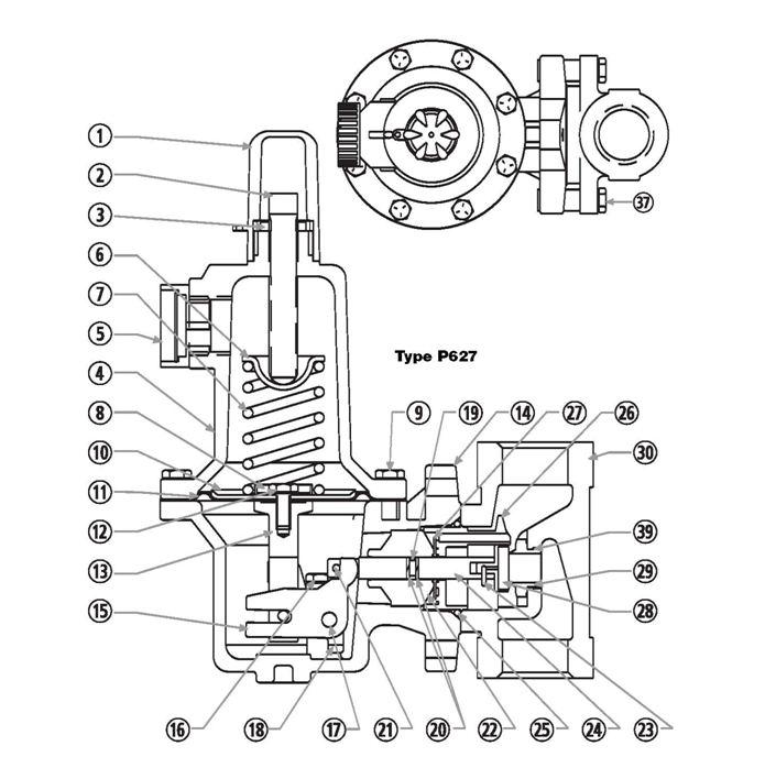
5 SHUTDOWN It is recommended that downstream pressure be released prior to performing a shutdown. Property damage or personal injury could result from an explosion from an overpressure condition on the diaphragm of the regulator. Begin the shut down procedure by closing the nearest upstream shutoff valve. Next close the nearest downstream shutoff valve. Open the pressure relief valve located between the regulator and the downstream shutoff valve. On the MEGR-1627, pressure between the upstream shutoff valve and the regulator will relieve through the regulator. The MEGR- 1627M requires relieving the pressure in the monitor line and downstream of the regulator prior to performing any maintenance. MAINTENANCE Severity of conditions and the requirements of both state and federal laws determine the frequency to which the regulators need to be inspected. Debris in the process lines, exterior damage, and normal wear could require the replacement of parts such as the disk assembly, seat ring, and diaphragm. The procedures below will provide assistance when attempting to replace these parts. When attempting any inspection or disassembly, relieve all pressure from the regulator and its adjacent piping so as to prevent personal injury or equipment damage as a result of an explosion or sudden pressure release. BODY MAINTENANCE PROCEDURES Replacing the Seat Assembly and/or Seat Orifice: 1. Remove the build screws (item 37) to separate the body (item 30) from the diaphragm case (item 14), exposing the seat assembly (item 28) and seat orifice (item 29). 2. Inspect the seat assembly (item 28) and the seat orifice (item 29) for damage, and if necessary, replace them. 3. To replace the seat assembly (item 28), remove the pin clip (item 23) which holds the seat assembly in place. 4. Assembly is the reverse of the above procedure. If replacing the seat orifice (item 29), apply thread locker (item 39) to the threads and torque to 16 ft/lbs. (aluminum case) and 25 ft/lbs.(steel case). Replacing the Stem Assembly (MEGR-1627): 1. Remove the boost body (item 26), the nitrile stabilizer (item 27), and the stem guide (item 22). 2. Disconnect the stem (item 24) and remove it from the diaphragm case (item 14). 3. Inspect the stem o-ring (item 19), the stem backup rings (item 20), and the diaphragm case o-ring (item 25) and replace if necessary. 4. Assembly is the reverse of the above procedure. Replacing the Stem Assembly (MEGR-1627M): 1. Using a straight edge screwdriver, pry the throat block (item 35) out of the diaphragm case (item 14). 2. Inspect the throat block o-rings (item 34), throat block backup rings (item 36), stem o-ring (item 19), and stem backup rings (item 20), and replace if necessary. 3. Assembly is the reverse of the above procedure. DIAPHRAGM & SPRING CASE AREA MAINTENANCE PROCEDURES Warning! Before performing the following steps, insure that all spring pressure has been released from the diaphragm case. 1. Remove the adjustment screw cap (item 1), loosen the locking nut (item 3) on the adjustment screw (item 2) and by turning counterclockwise release all compression from the range spring (item 7). 2. Remove the bonnet build screws (item 9) and lift off the bonnet (item 4). Range springs may be changed at this time. 3. Slip the pusher post (item 13) out of the groove in the lever (item 15) and remove the diaphragm assembly (items 10, 11, 12, & 13). 4. Remove the lever screws (item 16) and remove the lever (item 15). 5. Remove the diaphragm screw (item 12) to access the diaphragm (item 11). 6. Inspect and replace any worn or suspect parts. 7. Assembly is the reverse of this procedure. Torque the diaphragm screw to 7 ft-lbs (MEGR-1627 & MEGR- 1627M). Torque the spring case build screws to 7 ftlbs. (MEGR-1627 aluminum), 12 ft-lbs. (MEGR-1627 steel).
 Maximum pressure to spring and diaphragm casings to prevent burst of casings during abnormal operation.")
6 Maximum pressure to spring and diaphragm casing to prevent leak to atmosphere. (internal parts damage may occur) Maximum pressure to spring and diaphragm casings to prevent burst of casings during abnormal operation. (leak to atmosphere and internal parts may occur) Maximum diaphragm casing over pressure to prevent damage to internal parts. Spring & Diaphragm Casing Style Die Cast Aluminum Die Cast Aluminum MEGR-1627 MEGR-1627M PSIG BAR PSIG BAR N/A N/A N/A N/A ALL PARTS ORDERING When ordering replacement parts, always reference the Type number, which is found on the nameplate, and the item number of each needed part as found in the following parts list. PARTS LIST ITEM DESCRIPTION 1 Cover Adj. Screw 2 Adjustment Screw 3 Locknut 4 Bonnet 5 Vent Assembly 6 Spring Guide, Upper Range Spring: 5-20 PSIG-YELLOW, PSIG- 7 GREEN, PSIG-BLUE, PSIG-RED, PSIG-BLUE, PSIG-RED 8 Spring Guide, Lower 9 Build Screw, Spring Case (8 Required) 10 Diaphragm Piston 11 Diaphragm 12 Screw, Diaphragm 13 Post, Pusher 14 Diaphragm Case PARTS LIST ITEM DESCRIPTION 21 Pin, Groove 22 Stem Guide 23 Pin Clip 24 Stem 25 Diaphragm Case O-Ring 26 Boost Body 27 Stabilizer 28 Seat Assembly 29 Orifice 30 Body 31 Nameplate (not shown) 37 Build Screw 39 Thread Locker 40 Name Plate Drive Screw (2 Required)(not shown) 15 Lever 16 Lever Screw (2 Required) 17 Pin, Lever 18 Lever Retainer 19 Stem O-Ring 20 Stem Backup Ring (2 Required)
7 MEGR-1627
MEGR-1912 Instruction Manual
 MEGR-1912 PRESSURE REGULATOR Instruction Manual- Look Inside For: Description Installation Start-Up Maintenance Parts Ordering Parts List Marshall Excelsior Company Marshall, MI 49068 269-789-6700 FAX
627 Series Pressure Reducing Regulators
 Instruction Manual Form 5252 627 Series December 2006 627 Series Pressure Reducing Regulators NUMBER 1 10B3679-D NUMBER 2 W4793 Figure 1. Typical 627 Series Self-Operated Pressure Reducing Regulator Introduction
Types S100K and S102K Pressure Regulators
 Instruction Manual Form 5624 Types S0K and S2K 01/01 Types S0K and S2K Pressure Regulators W7478-1 Figure 1. Types S0K and S2K Pressure Regulator Introduction Scope of Manual This manual provides instructions
Type S301 & S302 Gas Regulators INTRODUCTION INSTALLATION. Scope of Manual. Description. Specifications. Type S301 and S302. Instruction Manual
 Fisher Controls Instruction Manual Type S301 & S302 Gas Regulators October 1981 Form 5180 WARNING Fisher regulators must be installed, operated, and maintained in accordance with federal, state, and local
299H Series. Introduction. P.E.D. Categories. Specifications. Installation. Warning. Installation Guide English September 2012
 Installation Guide English September 2012 299H Series Introduction This Installation Guide provides instructions for installation, startup, and adjustment of 299H Series regulators. To receive a copy of
1805 Series Relief Valves
 Instruction Manual Form 1211 1805 Series October 2011 1805 Series Relief Valves! WARNING Failure to follow these instructions or to properly install and maintain this equipment could result in an explosion
64 Series Pressure Reducing Regulators
 Instruction Manual Form 1245 64 Series March 2006 64 Series Pressure Reducing Regulators W1943 Figure 1. 64 Series Regulator Introduction Scope of Manual This manual provides instructions for the installation,
1305 Series Pressure Reducing Regulators
 Instruction Manual Form 1095 1305 Series October 2009 1305 Series Pressure Reducing Regulators! Warning Fisher regulators must be installed, operated, and maintained in accordance with federal, state,
Types S108K and S109K Pressure Reducing Regulators with Integral Slam-Shut Device
 Instruction Manual Form 5492 Types S108K and S109K May 1999 Types S108K and S109K Pressure Reducing Regulators with Integral Slam-Shut Device Introduction Fisher regulators must be installed, operated
627 Series Pressure Reducing Regulators
 627 Series Pressure Reducing Regulators Introduction The 627 Series direct-operated pressure reducing regulators (Figure 1) are for low and high-pressure systems. These regulators can be used with natural
Type HSR Pressure Reducing Regulator for Residential, Commercial, or Industrial Applications
 Instruction Manual Form 5753 Type HSR October 2003 Type HSR Pressure Reducing Regulator for Residential, Commercial, or Industrial Applications W8648 Figure 1. Type HSR Pressure Regulator Introduction
S300 Series. Valve Link. Features. Fisher Controls
 S0 Series Self-Operated Type VL FIELDVUE Regulators Valve Link Fisher Controls May 198 Bulletin 71.1:S0 The S0 Series self-operated, spring-loaded regulators are used for pressure-reducing control in a
Product Manual. Description. Specifications. CVS Type 1301F and CVS Type 1301G Regulator. Introduction
 Product Manual CVS Type 1301F and CVS Type 1301G Regulator Introduction This CVS Controls product manual includes instructions for the installation, adjustment, maintenance and parts ordering of the CVS
Type ACE97. Introduction. Installation. P.E.D. Categories. Specifications. Overpressure Protection. Installation Guide English May 2002
 Installation Guide English May 2002 Type ACE97 Introduction This installation guide provides instructions for installation, startup, and adjustment. To receive a copy of the instruction manual, contact
Type 1367 High-Pressure Instrument Supply System with Overpressure Protection
 Instruction Manual D100343X012 Type 1367 November 2017 Type 1367 High-Pressure Instrument Supply System with Overpressure Protection TYPE 252 FILTER 2ND-STAGE TYPE 67CF FILTER-STYLE REGULATOR INLET TYPE
OPERATING AND MAINTENANCE MANUAL
 Series 4300 Engineered Performance TABLE OF CONTENTS 0 INTRODUCTION 1 1 Scope 1 2 Description 1 3 Specifications 1 0 INSTALLATION 1 1 Mounting 1 2 Piping 1 1 Connecting Process Pressure 2 2 Vent Connections
Type R622 Pressure Reducing Regulator
 Type R622 Pressure Reducing Regulator June 2010 Compact Design Protective Inlet Screen High Capacity Internal Relief Light Weight W8806 Inlet and Outlet Pressure Gauge Taps Figure 1. Type R622 Pressure
INSTALLATION INSTRUCTIONS. CVS 67CFR Pressure Reducing Instrument Supply Regulator INTRODUCTION
 INSTALLATION INSTRUCTIONS CVS 67CFR Pressure Reducing Instrument Supply Regulator INTRODUCTION The CVS Controls 67CFR Filter regulator is a pressure reducing supply regulator typically used for pneumatic
1805 Series Relief Valves
 October 2011 1805 Series Relief Valves P1026 1805G Type 1805-2 Type 1805-4 Figure 1. Typical 1805 Relief Valves Introduction The 1805 Series relief valves are designed for use in farm tap applications
Types 95L and 95H Pressure Regulators
 Instruction Manual Form 1151 Types 95L and 95H July 1990 Types 95L and 95H Pressure Regulators W1888 W1888 W5652 Figure 1. NPT Body (Left), NPT Body (Middle), and Flanged Body (Right) Pressure Regulators
2.0 INSTALLATION & SERVICE
 Installation, Operation, and Maintenance Instructions MODEL 5600 / 5600R January 2005 CONTENTS 1.0 GENERAL 1.1 5600 Model Number Information -----------------------------------------------------------------------
1200B2 Series Service Regulators. Instruction Manual
 00B Series Service Regulators Instruction Manual 00B Series Service Regulators 0 Elster American Meter 00B Series Service Regulators General Information The 00B Series Service Regulators are available
Types 749B and R130 Changeover Manifolds
 Instruction Manual MCK-1179 Types 749B and R130 June 2012 Types 749B and R130 Changeover Manifolds TYPE HSRL-749B TYPE 64SR/122 TYPE R130/21 TYPE 749B/21 Figure 1. Changeover Manifolds and Regulator Assemblies
1301 Series High-Pressure Regulators
 Instruction Manual Form 1111 Types 1301F and 1301G March 2013 1301 Series High-Pressure Regulators! WARNING Failure to follow these instructions or to properly install and maintain this equipment could
1800C and 1800C-HC Series Service Regulators
 1800C and 1800C-HC Series Service Regulators Installation Instructions www.elster-americanmeter.com General Information: The 1800C and 1800C-HC Regulators are available as Full Capacity Internal Relief
Types S100C and S102C Pressure
 Instruction Manual Form 5404 Types S100C and S102C Types S100C and S102C Pressure Regulators Introduction Scope of Manual This manual provides instructions for the installation, adjustment, maintenance
T208VR Series Tank Blanketing Vacuum Regulator
 February 2014 T208VR Series Tank Blanketing Vacuum Regulator Figure 1. Typical T208VR Series Vacuum Regulator Introduction The T208VR Series direct-operated vacuum regulators are used where a decrease
INSTRUCTION MANUAL. CVS P37 LP Gas Reducing Regulator
 INSTRUCTION MANUAL CVS P37 LP Gas Reducing Regulator The CVS Controls P37 Regulator is a non-relieving, pressure reducing regulator suitable for use in LP gas applications (Natural Gas and Propane). As
CS800 Series Commercial / Industrial Pressure Reducing Regulators
 Instruction Manual D103124X012 CS800 Series April 2018 CS800 Series Commercial / Industrial Pressure Reducing Regulators P1235 P1234 TYPE CS800 REGULATOR TYPE CS800IQ WITH HIGH CAPACITY RELIEF P1521 TYPE
299H Series Pressure Reducing Regulators
 Instruction Manual D102684012 299H Series May 2017 299H Series Pressure Reducing Regulators! Warning Failure to follow these instructions or to properly install and maintain this equipment could result
Noth American 7347 High Pressure Gas Regulators
 Combustion Noth American 7347 High Pressure Gas s Bulletin 7347 7347 s reduce high gas supply pressures to practical use levels. Since capacities will vary with the pressure drop across the regulator (see
CSB400 Series Commercial / Industrial Pressure Reducing Regulators
 CSB400 Series Commercial / Industrial Pressure Reducing Regulators Bulletin 71.1:CSB400 April 2011 CSB400 SERIES PRESSURE REDUCING TYPICAL CSB403 WITH INTEGRAL TRUE-MONITOR TYPICAL CSB404 WITH INTEGRAL
PRO-50 Instrument Supply Regulator
 Features CRN Approved The PRO-50 Regulator has been granted a Canadian Registration Number. Sour Service Capability Available in NACE configurations that comply with NACE MR0175/MR0103. Environmental limits
299H Series Pressure Reducing Regulators
 Instruction Manual D102684012 299H Series May 2018 299H Series Pressure Reducing Regulators! Warning Failure to follow these instructions or to properly install and maintain this equipment could result
299H Series Pressure Reducing Regulators
 Instruction Manual Form 5497 299H Series January 2014 299H Series Pressure Reducing Regulators! WARNING Failure to follow these instructions or to properly install and maintain this equipment could result
Type FEQ Slam-Shut Valve
 Instruction Manual Form 5865 Type FEQ December 2012 Type FEQ Slam-Shut Valve Contents Introduction...1 Principle of Operation...1 Specifications...2 Installation...2 Commissioning...7 Adjustment...9 Shutdown...10
Regulator from 1800 B series
 Regulator from 1800 B series Regulator from 1800 B series Measuring of industrial gases frequently requests a precise pressure regulation for the purpose of dosage and proccesing. UNIS FAGAS has two kinds
TESCOM 50-4X Series Safety, Installation & Start-Up Procedures
 Operations & Service Manual TESCOM 50-4X Series Safety, Installation & Start-Up Procedures Do not attempt to select, install, use or maintain this product until you have read and fully understood this
CSB400 Series Commercial / Industrial Pressure Reducing Regulators
 October 2015 CSB400 Series Commercial / Industrial Pressure Reducing Regulators P1424 TYPE CSB400 PRESSURE REDUCING P1426 TYPICAL TYPE CSB403 WITH INTEGRAL TRUE-MONITOR P1425 TYPICAL TYPE CSB404 WITH INTEGRAL
T208 Series Tank Blanketing Vapor Recovery Regulators
 Instruction Manual T208 Series April 2014 T208 Series Tank Blanketing Vapor Recovery Regulators Table of Contents Introduction...1 Specifications...2 Principle of Operation...2 Installation...4 Startup,
630 Series Regulators and Relief Valves
 Instruction Manual Form 124 60 Series December 2015 60 Series Regulators and Relief Valves Introduction Scope of Manual This Instruction Manual provides operating, installation, maintenance and parts information
Type 310A-32A Pressure Reducing Regulator and Type 310A-32A-32A Working Monitor Regulator
 Instruction Manual Form 5351 Type 310A March 2010 Type 310A-32A Pressure Reducing Regulator and Type 310A-32A-32A Working Monitor Regulator! Warning Failure to follow these instructions or to properly
Type CT88 Backpressure Regulator
 Instruction Manual Type CT88 July 2016 Type CT88 Backpressure Regulator Table of Contents Introduction...1 Specifications...2 Principle of Operation...2 Installation...3 Overpressure Protection...4 Startup...4
Type FL Pressure Reducing Regulators
 Instruction Manual D103068X01 August 018 Pressure Reducing Regulators! Warning Failure to follow these instructions or to properly install and maintain this equipment could result in an explosion and/or
V DGX Series. Direct-Operated Regulators Manual D103834X012
 V2015.3 DGX Series Direct-Operated Regulators Manual D103834X012 Contents 1. Introduction... 3 2. Specifications... 3 3. Features... 3 4. Dimensions... 4 5. Principle of Operation... 5 6. Performance Curves...
Mooney * Noise Controller Installation, Operation, and Maintenance Manual
 GE Oil & Gas Mooney * Noise Controller Installation, Operation, and Maintenance Manual imagination at work Scope This manual provides instructions for installation, operation and maintenance of the Mooney
Type 310A-32A Pressure Reducing Regulator and Type 310A-32A-32A Working Monitor Regulator
 January 2009 Type 310A-32A Pressure Reducing Regulator and Type 310A-32A-32A Working Monitor Regulator Introduction The Type 310A pilot-operated high-pressure regulator (Figure 1) is used where high capacity
61 Series Pilots for Pilot-Operated Pressure Reducing Regulators
 Instruction Manual Form 583 Series June 20 Series Pilots for Pilot-Operated Pressure Reducing Regulators Failure to follow these instructions or to properly install and maintain this equipment could result
THE HF-300 SERIES. Operating and Service Manual. Series includes all variants of HF-300/301
 THE HF-300 SERIES Operating and Service Manual Series includes all variants of HF-300/301 Issue A July 2015 1 TABLE OF CONTENTS 1. Description... 3 2. Installation... 3 3. Operation... 4 3.1. Spring Loaded...
Model 141-A Regulators
 Regulator Installation and Maintenance Instructions Model -A Regulators RM- Rev. Introduction The Model -A regulator is both easy to use and durable for high pressure jobs. Thus, these field regulators
English. Introduction. Safety Instructions. All Products. Inspection and Maintenance Schedules. Parts Ordering. Specifications WARNING WARNING
 Contents All Products... Gb-1 Control Valves... Gb-2 Control Valve Actuators... Gb-3 Regulators... Gb-3 Relief Valves... Gb-4 Instruments, Switches, and Accessories... Gb-4 Products Covered by Battery
299H Series Pressure Reducing Regulators
 September 12 299H Series Pressure Reducing Regulators Inlet Pressure up to psig / 1 bar Compact ±1% Accuracy for Fixed Factor Billing (PFM) Rugged Construction Integral Pilot Easy to Maintain W713 Figure
Type 299 Pressure Reducing Regulators
 Type 299 Pressure Reducing Regulators Fisher, Fisher-Rosemount, and Managing The Process Better are marks owned by Fisher Controls International, Inc. or Fisher-Rosemount Systems, Inc. All other marks
Types 1808 and 1808A Pilot-Operated Relief Valves or Backpressure Regulators
 Types 1808 and 1808A Pilot-Operated Relief Valves or Backpressure Regulators July 2010 W3716 W3507 Type 1808 Type 1808A Figure 1. Types 1808 and 1808A Pilot-Operated Relief Valves or Backpressure Regulators
Type HSR Pressure Reducing Regulator for Residential, Commercial or Industrial Applications
 Instruction Manual Form 5753 Type HSR February 14 Type HSR Pressure Reducing Regulator for Residential, Commercial or Industrial Applications P154 TYPE HSR ANGLE BODY P175 TYPE HSR STRAIGHT Figure 1. Type
CS800 Series Commercial / Industrial Pressure Reducing Regulators
 Instruction Manual Form 5837 CS800 Series January 2012 CS800 Series Commercial / Industrial Pressure Reducing Regulators P1235 TyPICa CS800 REguaTOR P1234 P1521 TyPICa CS800IQ WITH HIgH CaPaCITy REIEF
Temperature Controllers
 IM0004 April 2013 CONTENTS T-12 Thermostat PAGE Introduction 1 Scope 1 Description 1 Specification 1 Temperature Controllers 2 INTRODUCTION CAUTION Prior to installing, the instructions provided herein
V DFX Series. Direct-Operated Tank Blanketing Regulator Manual D103808X012
 V2015.2 DFX Series Direct-Operated Tank Blanketing Regulator Manual D103808X012 Contents 1. Introduction... 3 2. Specifications... 3 3. Features... 3 4. Dimensions... 4 5. Principle of Operation... 4 6.
Type OS2 Slam-Shut Device
 Instruction Manual D102778X012 Type OS2 April 2018 Type OS2 Slam-Shut Device! Warning Failure to follow these instructions or to properly install and maintain this equipment could result in an explosion
CP200 Series Commercial / Industrial Pressure- Loaded Pressure Reducing Regulator
 CP200 Series Commercial / Industrial Pressure- Loaded Pressure Reducing Regulator May 2010 Figure 1. CP200 Series Pressure Loaded Regulator Features and Benefits Wide Range of NPT Body Sizes Easy to Install
THE MF-400 SERIES. Operating and Service Manual. Series includes all variants of MF-400/401
 THE MF-400 SERIES Operating and Service Manual Series includes all variants of MF-400/401 Issue A October 2013 1 TABLE OF CONTENTS 1. Description... 3 2. Installation... 3 3. Operation... 4 4. Special
THE BP-690 SERIES. Operating and Service Manual. Series includes all variants of BP-LF/MF-690/691
 THE BP-690 SERIES Operating and Service Manual Series includes all variants of BP-LF/MF-690/691 Issue B April 2015 1 TABLE OF CONTENTS 1. Description... 3 2. Installation... 3 3. Operation... 4 4. Special
Float Operated Level Controllers
 CONTENTS Float Operated Level Controllers IM0015 Nov. 2014 PAGE Introduction 1 Scope 1 Description 1 Specification 1 Control Installation 2 INTRODUCTION Side Mount Back Mount Prior to installing, the instructions
61 Series Pilots for Pilot-Operated Pressure Reducing Regulators
 61 Series Pilots for Pilot-Operated Pressure Reducing Regulators June 2011 Introduction 61 Series pilots are used with Types 1098-EGR and EZL pressure reducing regulators. These pilots can also be integrally
INDUSTRIAL VALVES MODELS: C62-A; C62-D. INSTRUCTION MANUAL Installation Operation Parts Service DIAPHRAGM BYPASS PRESSURE REGULATING VALVES
 INSTRUCTION MANUAL Installation Operation Parts Service IMPORTANT Record your Regulator model number and serial number here for easy reference: Model No. Serial No. Date of Purchase When ordering parts
VALVCHEQ BACKFLOW PREVENTERS FIGURE RP03
 Reduce pressure zone device suitable for high and medium hazard rated applications Flanged end connections FEATURES GENERAL APPLICATION The RP03 provides protection from both backsiphonage and backpressure
Types 627W and 627WH Direct-Operated Pressure Reducing Liquid Regulators
 Types 627W and 627WH Direct-Operated Pressure Reducing Liquid Regulators Introduction The Types 627W and 627WH are direct-operated pressure reducing regulators for liquid service. They are available in
RHPS Series RD(H)F40 User Manual. Read the complete manual before installing and using the regulator.
F40 User Manual. Read the complete manual before installing and using the regulator.") RHPS Series RD(H)F40 User Manual Read the complete manual before installing and using the regulator. 2 WARNING Before removing a regulator from the system for service, you must depressurize system purge
RHPS Series RD(H)F40 User Manual Read the complete manual before installing and using the regulator. 2 WARNING Before removing a regulator from the system for service, you must depressurize system purge
Models 461-S, 461-8S and S Regulators. R-1330 Rev. 7
 Models 461-S, 461-8S and 461-12S Regulators R-1330 Rev. 7 461-S, 461-8S and 461-12S Regulators The Sensus Models 461-S, 461-8S and 461-12S are balanced valve, spring type regulators designed for distribution
ANDERSON GREENWOOD SERIES 9000 POSRV INSTALLATION AND MAINTENANCE INSTRUCTIONS
 Procedure-assembly-functional test and performance requirements 1 SCOPE 1.1 This document establishes the general procedure for assembly, functional testing and normal performance requirements of low Series
Operation & Maintenance Manual Place this manual with valve or person responsible for maintenance of the valve
 Operation & Maintenance Manual Place this manual with valve or person responsible for maintenance of the valve Model CYCLE GARD II, CI & CNA YOUR PRODUCT INFORMATION: Model Number: Date: Serial Number:
THE BP-301 SERIES. Operating and Service Manual. Series includes all variants of BP-301 (LF 0.1Cv / MF 0.5Cv)
") THE BP-301 SERIES Operating and Service Manual Series includes all variants of BP-301 (LF 0.1Cv / MF 0.5Cv) Issue B October 2015 1 TABLE OF CONTENTS 1. Description... 3 2. Installation... 3 3. Operation...
THE BP-301 SERIES Operating and Service Manual Series includes all variants of BP-301 (LF 0.1Cv / MF 0.5Cv) Issue B October 2015 1 TABLE OF CONTENTS 1. Description... 3 2. Installation... 3 3. Operation...
Discontinued. Powers Controls. Technical Instructions Document No P25 RV Rev. 1, May, RV 201 Pressure Reducing Valves.
 Powers Controls RV 201 Pressure Reducing Valves Description Features Product Numbers Dual Pressure PRV Technical Instructions Document No. 155-049P25 RV 201-1 Single Pressure PRV The RV 201 Pressure Reducing
RS(H)20, 25 USER MANUAL
20, 25 USER MANUAL") RS(H)20, 25 USER MANUAL Read the complete manual before installing and using the regulator. WARNING Before removing a regulator from the system for service, you must depressurize system purge the system
RS(H)20, 25 USER MANUAL Read the complete manual before installing and using the regulator. WARNING Before removing a regulator from the system for service, you must depressurize system purge the system
Model 141-A Field Regulator. R-1311 Rev. 9
 Model 4-A Field Regulator R-3 Rev. 9 4-A Field Regulator The 4-A Field Regulator is for high pressure work such as feeding intermediate and small volume loads from gas transmission lines. Use this field
VALVCHEQ BACKFLOW PREVENTERS FIGURE RP03
 Reduce pressure zone device suitable for high and medium hazard rated applications BSP screwed connections FEATURES GENERAL APPLICATION The RP03 provides protection from both backsiphonage and backpressure
Type 1098-EGR. Pilot-Operated Valve Link Regulators. Features. Fisher Controls
 Type 1098-EGR and Type 1098H-EGR VL1000 FIELDVUE Pilot-Operated Valve Link Regulators Fisher Controls January 1982 Bulletin The Type 1098-EGR and Type 1098H-EGR regulators (figure 1) provide economical
DS05C,D,G Dial Set Pressure Regulating Valves
 DS05C,D,G Dial Set Pressure Regulating Valves APPLICATION The Honeywell DS05C,D,G Dial Set Pressure Regulating Valve is a high quality pressure regulating valve that maintains a constant outlet pressure
R122H, R222, R232A, and R232E Series Instruction Manual
 Instruction Manual MCK 2156 R122H, R222, R232A, and R232E Series October 2012 R122H, R222, R232A, and R232E Series Instruction Manual Failure to follow these instructions or to properly install and maintain
Models: C62/63/64-A/D
 Installation & Service C62-991-24A3 Models: C62/63/64-A/D Diaphragm Bypass Pressure Regulating Valves IMPORTANT Record your pump model number and serial number here for easy reference: Model No. Serial
RB Series Regulating System
 RB Series Instruction Manual Form 5872 January 2010 RB Series Regulating System filtration module RegulatoR module Box connecting Bolt outlet Ball valve inlet Ball valve Figure 1. RB Series Regulating
Type ACE95jr Tank Blanketing Valve
 Instruction Manual Form 5666 Type ACE95jr 04/01 Type ACE95jr Tank Blanketing Valve W8157 Introduction Scope of Manual Figure 1. Type ACE95jr Tank Blanketing Valve This instruction manual provides installation,
3 to 100 psig (0.21 to 6.9 bar) available in four ranges. Refer to Parts List Key 5 Maximum Emergency Outlet Pressure
 available in four ranges. Refer to Parts List Key 5 Maximum Emergency Outlet Pressure") Product Manual CVS Type 67AFR Filter Regulator Introduction This CVS Controls product manual includes instructions for the installation, adjustment, maintenance and parts ordering of the CVS Type 67AFR
Product Manual CVS Type 67AFR Filter Regulator Introduction This CVS Controls product manual includes instructions for the installation, adjustment, maintenance and parts ordering of the CVS Type 67AFR
CSB600 Series Commercial / Industrial Pressure Reducing Regulators
 Instruction Manual D103130X012 CSB600 Series August 2017 CSB600 Series Commercial / Industrial Pressure Reducing Regulators P2136 P2125 TYPE CSB600 TYPE CSB650 P2128 P2146 TYPE CSB604: CSB600 SERIES WITH
R600 and HSRL Series Instruction Manual
 Instruction Manual MCK 2141 November 2009 R600 and HSRL Series Instruction Manual! Warning Failure to follow these instructions or to properly install and maintain this equipment could result in an explosion
Maximum Pressure Differential and Maximum Inlet Pressure for Various Soft-Seated Valve Materials* Introduction. Body Pressure Ratings
 BR-G-REG-13-30-03-02-A* 461-S, 461-8S and 461-12S Regulators Brochure Introduction The Sensus Models 461-S, 461-8S and 461-12S are balanced valve, spring type regulators designed for distribution and industrial
D05 Pressure Regulating Valves
 D05 Pressure Regulating Valves FEATURES PRODUCT DATA Noncorroding unitized cartridge contains all working parts and is easily replaceable. Includes built-in strainer and thermal bypass. Balanced seat construction
RHPS Series PRV 6 User Manual
 RHPS Series PRV 6 User Manual Read the complete manual before installing and using the valve. 1 WARNING Before removing a valve from the system for service, you must depressurize system purge the system
CSB700 Series Commercial / Industrial Pressure Reducing Regulators
 Instruction Manual D103483X012 CSB700 Series May 2018 CSB700 Series Commercial / Industrial Pressure Reducing Regulators P2142 P2222 Type CSB700 Regulator Type CSB750 high pressure Regulator P2138 P2155
TECHNICAL DATA. Pressure Regulation 531a. April 24, 2009
 April 24, 29 Pressure Regulation 531a 1. DESCRIPTION The Viking Regulating Valve is a direct-acting, single-seated, spring-loaded diaphragm valve. When installed as a pilot regulating valve on a Viking
RS(H)10,15 USER MANUAL. Read the complete manual before installing and using the regulator.
10,15 USER MANUAL. Read the complete manual before installing and using the regulator.") RS(H)10,15 USER MANUAL Read the complete manual before installing and using the regulator. WARNING INCORRECT OR IMPROPER USE OF THIS PRODUCT CAN CAUSE SERIOUS PERSONAL INJURY AND PROPERTY DAMAGE. Due to
RS(H)10,15 USER MANUAL Read the complete manual before installing and using the regulator. WARNING INCORRECT OR IMPROPER USE OF THIS PRODUCT CAN CAUSE SERIOUS PERSONAL INJURY AND PROPERTY DAMAGE. Due to
TECHNICAL DATA. Page 1 of 12
 Page 1 of 12 1. DESCRIPTION The Viking Regulating Valve is a direct-acting, single-seated, spring-loaded diaphragm valve. When installed as a pilot regulating valve on a Viking Model H or J Flow Control
Pressure Regulators. Operating Instructions. Instrumentation
 Pressure Regulators Operating Instructions FAILURE OR IMPROPER SELECTION OR IMPROPER USE OF THIS PRODUCT CAN CAUSE DEATH, PERSONAL INJURY AND PROPERTY DAMAGE. This document and other information from the
Model 1800 PFM Series Regulator. Technical Bulletin
 Model 0 PFM Series Regulator Technical Bulletin Model 0 PFM Series Regulator 0 Elster American Meter The 0 PFM Series regulators are designed to control natural gas, air, nitrogen, carbon dioxide, propane
Installation Troubleshooting Maintenance Instructions Installation / Start-up
 Model ZW207 Installation Troubleshooting Maintenance Instructions Installation / Start-up NOTE: Flushing of all pipe lines is to be performed to remove all debris prior to installing valve. 1. For making
Y692VB Series Vacuum Breaker
 Y692VB Series Vacuum Breaker Bulletin 71.3:Y692VB June 2009 W7429 Figure 1. Type Y692VB Vacuum Breaker Introduction The Y692VB Series direct-operated vacuum breakers are used for the precise control of
Mooney* FlowMax* Regulator
 GE Oil & Gas Mooney* FlowMax* Regulator Instruction Manual (Rev. A) GE Data Classification : Public THESE INSTRUCTIONS PROVIDE THE CUSTOMER/OPERATOR WITH IMPORTANT PROJECT- SPECIFIC REFERENCE INFORMATION
DS06D,G Dial Set Pressure Regulating Valve
 DS06D,G Dial Set Pressure Regulating Valve PRODUCT DATA FEATURES APPLICATION Built-in, factory-calibrated outlet pressure adjustment dial. Noncorroding unitized cartridge contains all working parts and
North American 7339 High Pressure Gas Regulators
 Combustion North American 7339 High Pressure Gas Regulators Bulletin 7339 7339 Regulators reduce high gas supply pressures to practical use levels. Since capacities will vary with the pressure drop across
INSTALLATION, OPERATION, AND MAINTENANCE MANUAL WELKER RELIEF VALVE
 INSTALLATION, OPERATION, AND MAINTENANCE MANUAL WELKER RELIEF VALVE MODELS RV-1 RV-2 RV-2CP RV-3 DRAWING NUMBERS AD017A[ ] AD018A[ ] AD020A[ ] AD282BO MANUAL NUMBER IOM-033 REVISION Rev. E, 3/28/2016 TABLE