CALIBRATION KIT. Instruction Manual
|
|
|
- Horatio Perry
- 5 years ago
- Views:
Transcription


1 CALIBRATION KIT Instruction Manual
2 2 CALIBRATION KIT
3 CALIBRATION KIT 3 Table of Contents General description....4 Getting Started....4 GG-NH GG-NH3-2%....6 GG-CO....7 GG-CO2...8 GG-CL2...9 GG-H2-EC GG-H2S GG-NO GG-O GG-O GG-R GG-VL2-NH GG-VL2-CO GG-VL-R GG-EXP GG-LEL GG-LEL2-NH CO2 Responder NH3 Responder Multi-Gas Responder GasAlert Extreme Warranty
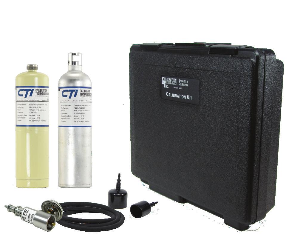
4 4 CALIBRATION KIT General Description The gas sensor Calibration Kit and replacement cylinders allow for field calibration of most fixed and portable gas detectors. This manual has been prepared to aid in the calibration of Calibration Technologies gas sensors. Please refer to the manual shipped with each piece of equipment for further information. Note: This manual includes the latest version of our sensors. Some or all features may be included in older versions of the sensor and the calibration procedure may or may not be identical. Refer to original sensor instruction manual calibration procedure if needed. The calibration kit may contain either one or two disposable bottles filled with the dry gas appropriate for the sensor. Also included in the kit are the following: Regulator with pressure gauge (2) Calibration adapters Hose The disposable certified gas cylinders are N.I.S.T. traceable. After initial purchase, replacement cylinders can be ordered at any time. Standard cylinder sizes include either 17 or 29 liter cylinders. The 17L cal kit will include a regulator (female fitting) for use with the CGA600 outlet fitting (male fitting) of the 17L cylinder. The 29L cal kit will include a regulator (male fitting) for use with the C-10 outlet fitting (female fitting) of the 29L cylinder. Because calibration gas has a shelf life, each bottle has an expiration date printed on it. Do not use the calibration gas after the expiration date. Each regulator is preset for 0.8 liters per minute with an easy on/off valve and includes a cylinder pressure gauge. The Calibration Kit also includes 3 feet of Norprene tubing and flexible calibration adaptors designed to fit most standard size gas cells and sensors. All kit accessories are enclosed in a durable hard carrying case with foam inserts. Getting Started Startup: Refer to sensor manual for power-up/warm-up procedures if power has recently been applied to the sensor, as some sensors may require a stabilization period before calibration is possible. It may be suitable to bypass external alarms and other equipment until the calibration of the sensor is completed, so as not to disrupt plant operations. Verification of alarm functions is recommended on a yearly basis. Alarm and readout verification: Because sensors are normally located at a distance from the main unit, the test time required and accuracy of the response checks will be improved if two people perform the start-up procedures and use radio contact. Ensure that the calibration gas concentration is equal to or greater than the alarm setpoints if alarm verification is required. Sensor element replacement: Below are a few response characteristics which may be an indication that the sensor element is at or near the end of its useful life. If any of these are observed, the sensor should be replaced: Slow response to / recovery from calibration gas. Failure of the output to reach 50% of the calibration gas value prior to span adjustment. Unable to achieve correct span output during calibration. Refer to sensor manual for more details. Calibration Guidelines: In highly critical areas, a response test should be performed between calibrations to verify proper sensor response and alarm functions. This can be done with bump gas, calibration gas or a gas sample. The response test is not required if multiple like sensors are installed in the same room. All tests and calibrations must be logged.
5 CALIBRATION KIT 5 GG-NH3 The GG-NH3 ammonia sensor comes factory calibrated and should require only minimal adjustments after installation. Calibration should be performed at 6-month intervals after installation. Note that some features may not be available on previous versions of the GG-NH3 sensor. There are two pots on the preamp that are used for calibration. Zero Calibration: After the sensor is installed and has been powered up for a minimum of 8 hours, the unit can be zero calibrated by the following: Be sure the unit is in clean air (target gas is not present) or apply Zero Air calibration gas at 0.5 to 0.8 L/min. Adjust the Zero pot until the sensor outputs 40 mv from Test [-] to Test [+]. Note: To zero the sensor immediately after power up or cell replacement, unplug the cell from the transmitter and adjust signal to 40 mv. Note: To enter calibration mode (disables all filtering and averaging), turn the Zero pot clockwise ¼ turn and then back again. Successful entry into calibration mode will be indicated by the Power (green) LED blinking twice per second. Calibration mode will time out automatically after 10 minutes. Span Calibration: Apply span gas at 0.5 to 0.8 L/min (span gas must be balanced in air, not nitrogen). Sensor should react to gas within 15 seconds. Once the output signal has peaked (or two minutes maximum) adjust the span pot until the correct output is achieved. The calculated span value with full-scale span gas is 200 mvdc. ((span gas / sensor range * ) *10). Example: ((250 ppm / 250 ppm x ) x 10) = 200 mvdc. Example: ((100 ppm / 250 ppm x ) x 10) = 104 mvdc. Calibration is now complete. Cell Sensor Cable plugs into socket here Zero adjustment mv mvdc Black Red - + Sensor Life: These electrochemical cells are extremely reliable with a typical cell life of 2-4 years in most applications. Several factors can cause the cell chemicals to become depleted including a long period of time, exposure to high temperatures and continuous, long term exposure to ammonia gas. When the cell becomes depleted, the unit will give no indication of failure other than that the sensor will not respond. Therefore, it is absolutely essential that these sensors be calibrated on a regular basis. Note: Rev A01 thru A10 sensors do not include the status LED or calibration mode
 and averaging.")
6 6 CALIBRATION KIT GG-NH3-2% Calibration should be performed six months after installation. There are two pots on the preamp that are used for calibration. Calibration Mode: Calibration mode is required for calibrating the sensor. Calibration mode clears the deadband (factory set at 4.8 ma) and averaging. Pressing the CAL switch enables cal mode and the green LED will flash. To exit out of cal mode, press the CAL switch or after 4 minutes it will automatically time-out. Zero Calibration: After the unit is installed and has been powered up for a minimum of 1 hour, the unit can be zero calibrated by the following: Be sure the unit is in clean air with no noticeable ammonia vapors. Press the CAL switch once to enter cal mode. Do not adjust the zero pot if the green LED is not flashing. Adjust the zero pot until the sensor outputs 40 mv from TP [-] to TP [+]. Span Calibration: Do not remove sensor housing cap during calibration. If green LED is not flashing, press the CAL switch once to enter cal mode. Apply 2% NH3 span gas at 0.5 to 0.8 L/min (span gas must be balanced in air, not nitrogen). Sensor should react to gas within 15 seconds. Once the output signal has peaked (or two minutes maximum) adjust the span pot until the correct output is achieved (200 mv). Calibration is now complete. Sensor Zero adjustment mv mvdc Black Red - + 4mA adjustment: Sometimes a fine adjustment of the 4mA signal may be desired to compensate for a slight positive or negative zero-signal reading on the control panel. Make sure the sensor is NOT in calibration mode. Adjust the 4mA pot until the control panel reads zero. Sensor life: These catalytic-bead long-life sensors have an expected life of 5-7 years in mechanical room applications.
7 CALIBRATION KIT 7 GG-CO There are two pots on the preamp that are used for calibration. Span calibration can be performed within 5 minutes after power-up, although best to wait 1 hour before adjusting the zero pot. Zero Calibration: After the sensor is installed and has been powered up for at least 1 hour, the unit can be zero calibrated by the following: Be sure the unit is in clean air. If unsure, apply Zero Air gas at 0.5 to 0.8 L/ min. Adjust the zero pot until the sensor outputs 40 mv from Test [-] to Test [+]. Note: To zero the sensor immediately after power up or cell replacement, unplug the cell from the transmitter and adjust signal to 40 mv. Span Calibration: Apply span gas at 0.8 L/min (span gas must be in air, not nitrogen). Sensor should react to gas within 15 seconds. Once the output signal has peaked (or two minutes maximum) adjust the span pot until the correct output is achieved. The calculated span value with full-scale span gas is 200 mvdc. ((span gas / sensor range * ) *10) Example 1: ((200 ppm / 200 ppm x ) x 10) = 200 mvdc. Example 2: ((100 ppm / 200 ppm x ) x 10) = 120 mvdc. Calibration is now complete. Sensor Life: These electrochemical cells have a typical cell life of 5 years. Several factors can cause the cell chemicals to become depleted including a long period of time, exposure to high temperatures and continuous, long term exposure to carbon monoxide. When the cell becomes depleted, the unit will give no indication of failure other than that the sensor will not respond. Therefore, it is absolutely essential to calibrate the sensor every six months. Cell Fault (red) LED: On steady if supply voltage is less than 10VDC. Status (amber) LED: Blinks once per second if RFI is detected. Power (green) LED: On steady to Indicate Power. Sensor Cable plugs into socket here Zero adjustment Blinks once per second for 60 seconds during power-up mv mvdc Black Red - + Blinks twice per second in calibration mode (4 minute timeout delay).
8 8 CALIBRATION KIT GG-CO2 Calibration should be performed at 6-month intervals after installation. There are two pots on the preamp that are used for calibration. Zero Calibration: After the unit is installed and has been powered up for a minimum of 2 hours, the unit can be zero calibrated by the following: Apply 500 ppm CO 2 gas at 0.5 to 0.8 L/min. Adjust the zero pot until the voltmeter reads the following mvdc on the test points [-] to [+]. 0-1% CO 2 range sensor = 48.0 mvdc 0-3% CO 2 range sensor = 42.7 mvdc 0-5% CO 2 range sensor = 41.6 mvdc mv mvdc Black Red - + Span and zero adjustments Calibration gas port Span Calibration: Connect tubing to the calibration port of the infrared tube. Apply span gas at 0.5 to 0.8 L/min. Sensor should react to gas within 10 seconds. Once the output signal has peaked (or two minutes maximum) adjust the span pot until the correct output is achieved. The calculated span value with full-scale span gas is 200 mvdc. (span gas / sensor range * ) *10) Example 1: (3% / 3% x ) x 10) = 200 mvdc. Example 2: (1% / 3% x ) x 10) = 93.3 mvdc. Calibration is now complete. Sensor Life: Typical sensor life of the GG-CO2 is five to seven years. Failure of the infrared sensor is typically caused when the infrared source opens or breaks, similar to an incandescent light bulb filament. If this occurs, the sensor will produce a continuous fault indication signal of 0.5 ma and the fault LED will be lit. Contact Calibration Technologies for a sensor replacement.
9 CALIBRATION KIT 9 GG-CL 2 Calibration should be performed at 6-month intervals after installation. There are two pots on the preamp that are used for calibration. Zero Calibration: After the sensor is installed and has been powered up for a minimum of 8 hours, the unit can be zero calibrated by the following: Be sure the unit is in clean air. Adjust the Zero pot until sensor outputs 40 mv from Test [-] to Test [+]. Note: To zero the sensor immediately after power up or cell replacement, unplug the cell from the transmitter and adjust signal to 40 mv. Cell Sensor Cable plugs into socket here Zero adjustment mv mvdc Span Calibration: Apply span gas at 0.8 L/min (span gas balance can be air or nitrogen). Sensor should react to gas within 15 seconds. Once the output signal has peaked (or two minutes maximum) adjust the span pot until the correct output is achieved. The calculated span value with full-scale span gas is 200 mvdc. (span gas / sensor range * ) *10) Example 1: ((5 ppm / 5 ppm x ) x 10) = 200 mvdc. Example 2: ((3 ppm / 5 ppm x ) x 10) = 136 mvdc. Calibration is now complete. Sensor Life: Typical cell life will be two to three years. Several factors can cause the cell chemicals to become depleted including a long period of time, exposure to high temperatures and continuous, long term exposure to chlorine gas. When the cell becomes depleted, the unit will give no indication of failure other than that the sensor will not respond. Therefore, it is absolutely essential to calibrate the sensor every six months. Fault (red) LED: On steady if supply voltage is less than 10VDC. Status (amber) LED: Blinks once per second if RFI is detected. Power (green) LED: On steady to Indicate Power. Blinks once per second for 60 seconds during power-up. Black Red - + Blinks twice per second in calibration mode (4 minute timeout delay).
10 10 CALIBRATION KIT GG-H2-EC The GG-H2 sensor should be calibrated at 6-month intervals after installation. There are two pots on the preamp that are used for calibration. Zero Calibration: After the unit is installed and has been powered up for a minimum of 12 hours, the unit can be zero calibrated by the following: Be sure the unit is in clean air, otherwise apply zero air. Adjust the zero pot until the sensor outputs 40 mv from Test [-] to Test [+]. Span Calibration: Perform zero adjustment before spanning. Apply span gas at 0.5 to 0.8 L/min (span gas must be in air, not nitrogen or other carrier). Sensor should react to gas within 10 seconds Once the output signal has peaked (or two minutes maximum) adjust the span pot until the correct output is achieved. Cell Sensor Cable plugs into socket here Zero adjustment mv mvdc Black Red - + Sensor Life: Typical cell life will be two to three years. Several factors can cause the cell chemicals to become depleted including a long period of time, exposure to high temperatures and continuous, long term exposure to hydrogen gas. When the cell becomes depleted, the unit will give no indication of failure other than that the sensor will not respond. Therefore, it is absolutely essential to calibrate the sensor every six months. Fault (red) LED: On steady if supply voltage is less than 10VDC. Status (amber) LED: Blinks once per second if RFI is detected. Power (green) LED: On steady to Indicate Power. Blinks once per second for 60 seconds during power-up. Blinks twice per second in calibration mode (4 minute timeout delay).
11 CALIBRATION KIT 11 GG-H2S The GG-H2S sensor should be calibrated at 6-month intervals after installation. There are two pots on the preamp that are used for calibration. Zero Calibration: After the sensor is installed and has been powered up for a minimum of 12 hours, the unit can be zero calibrated by the following: Be sure the unit is in clean air (target gas is not present) or else apply Zero Air calibration gas at 0.5 to 0.8 L/min. Adjust the zero pot until the sensor outputs 40 mv from Test [-] to Test [+]. Span Calibration: Apply span gas at 0.5 to 0.8 L/min (span gas must be in air, not nitrogen). Sensor should react to gas within 15 seconds. Once the output signal has peaked (or two minutes maximum) adjust the span pot until the correct output is achieved. The calculated span value with full-scale span gas is 200 mvdc. ((span gas / sensor range * ) *10) Calibration is now complete. Sensor Life: These electrochemical cells are extremely reliable with a typical cell life of 3-4 years in most applications. Several factors can cause the cell chemicals to become depleted including a long period of time, exposure to high temperatures and continuous, long term exposure to hydrogen sulfide gas. When the cell becomes depleted, the unit will give no indication of failure other than that the sensor will not respond. Therefore, it is absolutely essential that these sensors be calibrated on a regular basis. Cell Sensor Cable plugs into socket here Zero adjustment mv mvdc Black Red - + Fault (red) LED: On steady if supply voltage is less than 10VDC. Status (amber) LED: Blinks once per second if RFI is detected. Power (green) LED: On steady to Indicate Power. Blinks once per second for 60 seconds during power-up. Blinks twice per second in calibration mode (4 minute timeout delay).
12 12 CALIBRATION KIT GG-NO2 The GG-NO2 should be calibrated at 6-month intervals after installation. There are two pots on the preamp that are used for calibration Zero Calibration: After the sensor is installed and has been powered up for a minimum of 8 hours, the unit can be zero calibrated by the following: Be sure the unit is in clean air. Adjust the zero pot until the sensor outputs 40 mv from Test [-] to Test [+]. Span Calibration: To enter calibration mode (disables all filtering and averaging), turn the Zero pot clockwise 1/4 turn and then back again. Successful entry into calibration mode will be indicated by the Power (green) LED blinking twice per second. Calibration mode will time out automatically after 4 minutes. Apply span gas at 0.5 to 0.8 L/min (span gas must be in air, not nitrogen or other carrier). Sensor should react to gas within 15 seconds. Once the output signal has peaked (or 5 minutes maximum) adjust the Span pot until the correct output is achieved. With full-scale span gas, the calculated span value is 200 mv. ((span gas / sensor range * ) (ma output)) Sensor Life: Typical cell life will be two to three years. Several factors can cause the cell chemicals to become depleted including a long period of time, exposure to high temperatures and continuous, long term exposure to nitrogen dioxide. When the cell becomes depleted, the unit will give no indication of failure other than that the sensor will not respond. Therefore, it is absolutely essential to calibrate the sensor every six months. Cell Sensor Cable plugs into socket here Zero adjustment mv mvdc Black Red - + Fault (red) LED: On steady if supply voltage is less than 10VDC. Status (amber) LED: Blinks once per second if RFI is detected. Power (green) LED: On steady to Indicate Power. Blinks once per second for 60 seconds during power-up. Blinks twice per second in calibration mode (4 minute timeout delay).
13 CALIBRATION KIT GG-O2 The GG-O2 should be calibrated at 6-month intervals after installation. After the sensor is installed and has been powered up for a minimum of 1 hour, the sensor can be calibrated. There are two pots on the preamp that are used for calibration voltmeter settings on sensor test points. Note: Adjusting the span to achieve a 20.9% reading can be done with calibration gas or in clean air. Span Calibration: Apply 20.9% O2 span gas at 0.5 to 0.8 L/min. Once the output signal has peaked (or 2 minutes maximum), adjust the span pot until the correct output is achieved. Note: Calculated span values 0-25% range = mv from Test [-] to Test [+] 15-25% range = mv from Test [-] to Test [+] Zero Calibration: Apply zero calibration gas (nitrogen or 15% O2 depending on range of sensor) at 0.5 to 0.8 L/min. Once the output has settled (or 2 minutes maximum), adjust the zero pot until the sensor outputs 40 mv from Test [-] to Test [+]. Sensor Life: Typical sensor life in 20.9% oxygen is three years. When the cell becomes depleted, a replacement cell can be obtained from Calibration Technologies. Simply unplug the cell s ribbon cable from the transmitter, pull the old cell from the spring clip, discard the old cell and replace it with a new one. Cell Sensor Cable plugs into socket here Zero adjustment mv mvdc Black Red
14 14 CALIBRATION KIT GG-O3 The GG-O3 ozone sensor should be calibrated at 6-month intervals after installation. There are two pots on the preamp that are used for calibration. Zero Calibration: After the unit is installed and has been powered up for a minimum of 12 hours, the unit can be zero calibrated by the following: Be sure the unit is in clean air (target gas is not present) or else apply Zero Air calibration gas at 0.5 to 1.0 L/min. Adjust the zero pot until the sensor outputs 40 mv from Test [-] to Test [+]. Span Calibration: Never adjust the span pot without an ozone generator. Perform zero adjustment before spanning. Apply span gas at 0.5 to 1.0 L/min. Sensor should react to gas within 20 seconds. Once the output signal has peaked (or 5 minutes maximum) adjust the span pot until the correct output is achieved. Calibration is now complete. Note: If an ozone generator is not available, the unit can be calibrated with chlorine. The relative response of the ozone sensor to chlorine is 1:1. To calibrate with chlorine, apply 1.0 ppm and adjust output to ma. Sensor Life: Typical cell life will be two years. Several factors can cause the cell chemicals to become depleted including a long period of time, exposure to high temperatures and continuous, long term exposure to ozone or chlorine. When the cell becomes depleted, the unit will give no indication of failure other than that the sensor will not respond. Therefore, it is absolutely essential that these sensors be calibrated on a regular basis. Cell Fault (red) LED: On steady if supply voltage is less than 10VDC. Status (amber) LED: Blinks once per second if RFI is detected. Power (green) LED: On steady to Indicate Power. Blinks once per second for 60 seconds during power-up. Sensor Cable plugs into socket here Zero adjustment mv mvdc Black Red - + Blinks twice per second in calibration mode (4 minute timeout delay).

15 CALIBRATION KIT 15 GG-R The GG-R refrigerant sensor should be calibrated at 6-month intervals after installation. There are two pots on the preamp that are used for calibration. Zero Calibration: After the unit is installed and has been powered up for a minimum of 2 hours, the unit can be zero calibrated by the following: Activate calibration mode by pressing the CAL MODE button (green LED will flash). Be sure the unit is in clean air (target gas is not present) or else apply Zero Air calibration gas (or nitrogen) at 0.3 to 0.8 L/min. Adjust the zero pot until the sensor outputs 40 mvdc from test points TP [-] to TP [+]. Span Calibration: Perform zero calibration prior to spanning. Connect tubing to the calibration port of the infrared tube. Apply span gas at 0.3 to 0.8 L/min. Sensor should react to gas within 10 seconds. The adjustment response is dampened. Make slight adjustments (no more than ½ turn of the potentiometer) and wait for output response. Once the output signal has peaked (or two minutes maximum) adjust the span pot until the correct output is achieved. The calculated span value with fullscale span gas is 200 mvdc. ((span gas / sensor range * ) *10) Example 1: ((500 ppm / 500 ppm x ) x 10) = 200 mvdc. Example 2: ((500 ppm / 1000 ppm x ) x 10) = 120 mvdc. Calibration is now complete mv mvdc Black Red - + Calibration gas port Zero adjustment Sensor Life: Expected sensor life of the GG-R is seven to ten years. Failure of the infrared sensor is typically caused when the infrared optics reach the end of their useful life. If this occurs, the sensor will produce a continuous fault indication signal of 0.5 ma and the fault LED will be lit. Field replacement of the sensor optics is not available at this time. Contact Calibration Technologies for sensor repair or replacement.
16 16 CALIBRATION KIT GG-VL2-NH3 The GG-VL2-NH3 vent line sensor should be calibrated at 6-month intervals after installation. There are two pots on the preamp that are used for calibration. Note: Do not response test with propane or MAPP gas, as these can shorten sensor life! Calibration Mode: Cal mode is required for calibrating the sensor. It clears the averaging, latching and deadband (factory set to 8 ma). Pressing the CAL switch enables cal mode and the green LED will flash. To exit out of cal mode, press the CAL switch or after 6 minutes it will automatically time-out back to normal mode. Zero Calibration: After the unit is installed and has been powered up for a minimum of 1 hour, the unit can be zero calibrated by the following: Be sure the unit is in clean air. When in doubt, apply zero air gas. Press the CAL switch to enter cal mode. Do not adjust the zero pot if the green LED is not flashing. Adjust the zero pot until sensor outputs 40 mvdc from Test [-] to Test [+]. Span Calibration: Do not adjust the span pot without certified calibration gas! If span adjustment is required, use the following procedure. Unscrew calibration port cover and connect cal gas hose to hose barb fitting Press the CAL switch once to enter cal mode. Apply 1% NH3 span gas at 0.8 L/min (span gas must be in air, not nitrogen or other carrier). Sensor should react to gas within 15 seconds. Once the output signal has peaked (or 2 minutes maximum) adjust the span pot until the correct output is achieved (200 mvdc). Shut-off gas, remove hose and replace cover. Press the CAL switch to exit cal mode. Calibration is now complete. Sensor cable plug Sensor element assembly Calibration port Unscrew cap to apply calibration gas Calibration switch Push to enter cal mode mv mvdc Black Red - + Note: Allow up to an hour for the signal to return back to 4 ma after exposure to high concentrations. Note: If correct output during span adjustment is unachievable, replace sensor element. Note: Gas exposures well above the 0-1% NH3 range of the sensor can shorten the life of the sensor element, and typically results in a "zero signal shift", where the signal is stuck at full-scale levels. Make sure no ammonia gas is present and simply re-zero the sensor following the Zero Calibration procedure. 4mA adjustment: Sometimes a fine adjustment of the 4mA signal may be desired to compensate for a slight positive or negative zero-signal reading on the control panel. Make sure the sensor is NOT in calibration mode. Adjust the 4mA pot until the control panel reads zero.

17 CALIBRATION KIT GG-VL2-CO2 The GG-VL2-CO2 vent line sensor should be calibrated at 6-month intervals after installation. There are three pots on the preamp that are used for calibration. Calibration Mode: Cal mode is required for calibrating the sensor. Pressing the CAL switch enables cal mode and the green LED will flash. To exit out of cal mode, press the CAL switch or after 6 minutes it will automatically timeout back to normal mode. Zero Calibration: After the unit is installed and has been powered up for a minimum of 5 minutes, the unit can be zero calibrated by the following: Press the CAL switch to enter cal mode. Do not adjust the zero pot if the green LED is not flashing. Apply Zero Air calibration gas at L/min. Adjust the zero pot until the sensor outputs 40 mvdc from Test [-] to Test [+] Span Calibration: If span adjustment is required, use the following procedure: Unscrew calibration port cover and connect cal gas hose to hose barb fitting Press the CAL switch once to enter cal mode. Apply 5% CO2 span gas at L/min. Sensor should react to gas within 15 seconds. Once the output signal has peaked (or 2 minutes maximum) adjust the span pot until the correct output is achieved (200 mvdc). Shut-off gas, remove hose and replace cover. Press the CAL switch to exit cal mode. Calibration is now complete. Sensor cable plug Sensor element assembly mv mvdc Black Red Calibration port Unscrew cap to apply calibration gas Calibration switch Push to enter cal mode Note: Depending on sensor s proximity to fresh air, allow up to an hour for the signal to return back to 4 ma after exposure to high concentrations. Applying Zero Air calibration gas to the sensor will help purge the CO2 gas from the sensor element, and return the signal back to normal. Note: If correct output during span adjustment is unachievable, replace sensor element. 4mA adjustment: Sometimes a fine adjustment of the 4mA signal may be desired to compensate for a slight positive or negative zero-signal reading on the control panel. Make sure the sensor is NOT in calibration mode. Adjust the 4mA pot until the control panel reads zero.

![This can be accomplished by removing the sensor from the mounting kit into fresh air. Adjust the zero pot until the sensor outputs 40 mv from Test [-] to Test [+].](/docs-images/89/98224788/images/18-2.jpg "Span Calibration: It is recommended that the GG-VL-R sensor be response tested only, every six months. Refer to the Response Test procedure below. Response Test: 1.")
18 18 CALIBRATION KIT GG-VL-R The GG-VL-R vent line sensor should be calibrated at 6-month intervals after installation. There are two pots on the preamp that are used for calibration. Zero Calibration: After the unit is installed and has been powered up for a minimum of 24 hours, the unit can be zero calibrated by the following: Be sure the unit is in clean air. This can be accomplished by removing the sensor from the mounting kit into fresh air. Adjust the zero pot until the sensor outputs 40 mv from Test [-] to Test [+]. Span Calibration: It is recommended that the GG-VL-R sensor be response tested only, every six months. Refer to the Response Test procedure below. Response Test: 1. One person removes the ½ plug in the tee and injects a small amount of propane/butane from an unlit plumber s torch. 2. The second person stays at the control panel to determine that each sensor, when exposed to the gas, is connected to the proper input and responds, causing appropriate alarm functions.


, turn the Zero pot clockwise 1/4 turn and then back")
19 CALIBRATION KIT GG-EXP 19 Since the zero and span calibration procedures are the same for the EXP series gas sensors, refer to the specific gas sensor in the previous pages. The generic procedures below can also be used. The GG-EXP should be calibrated every six months after installation. There are two pots on the preamp that are used for calibration. Zero Calibration: After the sensor is installed and has been powered up for a minimum of 8 hours, the unit can be zero calibrated by the following: Be sure the unit is in clean air. Adjust the Zero pot until the sensor outputs 40 mv from TP [-] to TP [+]. Note: To zero the sensor immediately after power up or cell replacement, unplug cell from the transmitter and adjust signal to 40 mv. Span Calibration: If span adjustment is required, use the following procedure: To enter calibration mode (disables all filtering and averaging), turn the Zero pot clockwise 1/4 turn and then back again. Successful entry into calibration mode will be indicated by the Power (green) LED blinking twice per second. Calibration mode will time out automatically after 4 minutes. Apply span gas at 0.5 to 0.8 L/min. Sensor should react to gas within 15 seconds. Once the output signal has peaked (or 2 minutes maximum) adjust the Span pot until the correct output is achieved. With full-scale span gas, the calculated span value is 200 mv. Zero adjustment Sensor head plugs in here Sensor element Fault (red) LED: On steady if supply voltage is less than 10VDC. Status (amber) LED: Blinks once per second if RFI is detected. Power (green) LED: On steady to Indicate Power. Blinks once per second for 60 seconds during power-up. Blinks twice per second in calibration mode (4 minute timeout delay).
20 20 CALIBRATION KIT GG-LEL2 The combustible gas sensor has a slightly different response to each combustible gas or vapor. Because of these factors, a combustible transmitter must be adjusted differently if the system is meant to detect a gas or vapor other than methane. 2.5% methane gas can be used for calibration of the combustible transmitter when used for other gases. The voltage that you set at the transmitter test point will be different for each gas. The table below provides the voltage setting for various gases. Relative Response Table Gas Voltage (mvdc) Gas Voltage (mvdc) Methane 120 n-hexabe 200 Propane 163 Hydrogen 111 n-butane 163 Ethane 139 n-pentane 183 Ethylene 168 Note: Ensure area is free from explosive gases before removing cover while sensor is energized. The GG-LEL2 sensor should be calibrated every six months after installation. There are two pots on the preamp that are used for calibration. Calibration Mode: Cal mode is required for calibrating the sensor. It clears the deadband (factory set at 4.8 ma) and averaging. Pressing the CAL switch enables cal mode and the green LED will flash. To exit out of cal mode, press the CAL switch or after 6 minutes it will automatically time-out. Zero Calibration: After the unit is installed and has been powered up for a minimum of 1 hour, the unit can be zero calibrated by the following: Press the CAL switch once to enter cal mode. Do not adjust the zero pot if the green LED is not flashing. Be sure the unit is in clean air. If unsure, apply zero air gas to the sensor to properly zero calibrate. Adjust the zero pot until the sensor outputs 40 mv from Test [-] to Test [+] Calibration switch Zero adjustment Sensor head plugs in here Sensor head Fault (red) LED: On steady if supply voltage is less than 10VDC. Status (amber) LED: Blinks once per second if RFI is detected. Power (green) LED: On steady to Indicate Power. Blinks once per second for 60 seconds during power-up. Blinks twice per second in calibration mode. Span Calibration: If span adjustment is required, the following procedure will span the unit: Apply 2.5% CH4 span gas at 0.5 to 0.8 L/min (span gas must be in air, not nitrogen or other carrier). Sensor should react to gas within 15 seconds. Once the output signal has peaked (or 2 minutes maximum) adjust the span pot until the correct output is achieved (see Relative Response Table). Calibration is now complete. 4mA adjustment: Sometimes a fine adjustment of the 4mA signal may be desired to compensate for a slight positive or negative zero-signal reading on the control panel. Make sure the sensor is NOT in calibration mode. Adjust the 4mA pot until the control panel reads zero.

21 CALIBRATION KIT 21 GG-LEL2-NH3 The combustible gas sensor has a slightly different response to each combustible gas or vapor. Therefore, a combustible transmitter can be calibrated with different gases, as long as the relative response is known. It s always best to use the target gas for calibration, but sometimes the target gas is difficult to obtain in certain concentrations. The voltage that you set at the transmitter test point will be different for each gas. The following table provides voltage settings for both recommended calibration gases. Relative Response Table Gas Voltage (mvdc) 2% Ammonia % Methane 120 Note: Ensure area is free from explosive gases before removing cover while sensor is energized. The GG-LEL2-NH3 sensor should be calibrated every six months after installation. There are two pots on the preamp that are used for calibration. Calibration Mode: Cal mode is required for calibrating the sensor. It clears the deadband (factory set at 4.8 ma) and averaging. Pressing the CAL switch enables cal mode and the green LED will flash. To exit out of cal mode, press the CAL switch or after 6 minutes it will automatically time-out. Zero Calibration: After the unit is installed and has been powered up for a minimum of 1 hour, the unit can be zero calibrated by the following: Press the CAL switch once to enter cal mode. Do not adjust the zero pot if the green LED is not flashing. Be sure the unit is in clean air. If unsure, apply zero air gas to the sensor to properly zero calibrate. Adjust the zero pot until the sensor outputs 40 mv from Test [-] to Test [+]. Span Calibration: If span adjustment is required, the following procedure will span the unit: Apply span gas at 0.5 to 0.8 L/min (span gas must be in air, not nitrogen or other carrier). Calibration switch Zero adjustment Sensor head plugs in here Sensor head Fault (red) LED: On steady if supply voltage is less than 10VDC. Status (amber) LED: Blinks once per second if RFI is detected. Power (green) LED: On steady to Indicate Power. Blinks once per second for 60 seconds during power-up. Blinks twice per second in calibration mode. Sensor should react to gas within 15 seconds. Once the output signal has peaked (or 2 minutes maximum) adjust the span pot until the correct output is achieved. Calibration is now complete. 4mA adjustment: Sometimes a fine adjustment of the 4mA signal may be desired to compensate for a slight positive or negative zero-signal reading on the control panel. Make sure the sensor is NOT in calibration mode. Adjust the 4mA pot until the control panel reads zero.
22 22 CALIBRATION KIT CO2 Responder The CO2 Responder portable carbon dioxide detector comes factory calibrated and should require only minimal adjustments after purchase. Calibration should be performed at 6-month intervals. Note: Verify that the calibration gas being used matches the span concentration value(s) that are set for the detector in the User Options Menu. Refer to Span Gas Value section in the operating manual. Required calibration gas: CO2: 1% CO2 balance air Start Calibration 1. To enter calibration, press and hold and simultaneously as the detector beeps, flashes, and vibrates to the corresponding countdown. The detector then reads Starting calibration. Auto Zero 2. Auto Zero flashes while the detector automatically zeroes the sensors. Do not apply calibration gas during this process, otherwise the auto zero step will fail. Auto Span 3. Next, three screens are displayed: - Apply span gas now to calibrate (recommended) (skip to step #4) - or press to select sensor(s) - or press to skip calibration (skip to step #5) Apply Span Gas Now 4. Attach the calibration hose and apply gas to the sensor(s) at a flow rate of 500 ml/min. The cal gas cylinder icon flashes as the detector initially detects the calibration gas. After 30 seconds the detector beeps and the cal gas cylinder stops flashing. Auto Span flashes while spanning the sensors until the detector has attained a sufficient level of the expected gas. 5. When the span is complete, the following screens are displayed: - Calibration successful - Press to apply new cal gas (repeat step #4) - Press to end span Remove hose and turn off cal gas. The display then advises to press to set or to bypass the calibration due dates.

23 CALIBRATION KIT NH3 Responder 23 The NH3 Responder portable ammonia detector comes factory calibrated and should require only minimal adjustments after purchase. Calibration should be performed at 6-month intervals. Note: Verify that the calibration gas being used matches the span concentration values that are set for the detector in the Use Option Menu. Refer to Span Gas Value section on page 8 of the operating manual. Correction factors are not applied during calibration. Correction factors that were set prior to calibration are restored when the detector returns to normal operation. Selecting sensor(s) to be calibrated (during Auto Span) is not necessary for calibration of the PID and LEL sensors as the cal gas being used will only be detected by its corresponding sensor. Required calibration gas: PID: 250 ppm Ammonia, balance air LEL: 50% LEL Methane (2.5%), balance air Start Calibration 1. To enter calibration, press and hold and simultaneously as the detector beeps, flashes, and vibrates to the corresponding countdown. The detector then reads Starting calibration. Auto Zero 2. Auto Zero flashes while the detector automatically zeroes the sensors. Do not apply calibration gas during this process, otherwise the auto zero step will fail. Auto Span 3. Next, three screens are displayed: - Apply span gas now to calibrate (recommended) (skip to step #4) - or press to select sensor(s) - or press to skip calibration (skip to step #5) Apply Span Gas Now 4. Attach the calibration hose and apply gas to the unit at a flow rate of 0.5 to 0.8 l/min. The cal gas cylinder icon flashes as the detector initially detects the calibration gas. After 30 seconds the detector beeps and the cal gas cylinder stops flashing. Auto Span flashes while spanning the respective sensor until the detector has attained a sufficient level of the expected gas. 5. When the span is complete, the following screens are displayed: - Calibration successful - Press to apply new cal gas (repeat step #4) - Press to end span Remove hose and turn off cal gas. The display then advises to press to set or to bypass the calibration due dates.

24 24 CALIBRATION KIT 4-Gas Responder Calibration Procedure (AutoCal) Verify that the calibration gas being used matches the span concentration values that are set for the detector. Refer to Span Gas Value section on page 9. Start Calibration 1. To enter calibration, press and hold and simultaneously as the detector beeps, flashes, and vibrates to the corresponding countdown. The detector then reads Starting calibration. Auto Zero 2. Auto Zero flashes while the detector automatically zeroes the sensors. Do not apply calibration gas during this process, otherwise the auto zero step will fail. Auto Span 3. Next, three screens are displayed: - Apply span gas now to calibrate (recommended) (skip to step #4) - or press to select sensor(s) - or press to skip calibration (skip to step #5) Apply Span Gas Now 4. Note: turn on gas flow prior to connecting to the portable to prevent a pump failure alarm. Attach the calibration hose to the regulator outlet and apply gas to the unit at a flow rate of 0.5 to 0.8 l/min. The cal gas cylinder icon flashes as the detector initially detects the calibration gas. After 30 seconds the detector beeps and the cal gas cylinder stops flashing. Auto Span flashes while spanning the respective sensor until the detector has attained a sufficient level of the expected gas. Wait until the spanning countdown is complete. 5. When the span is complete, the following screens are displayed: - Calibration successful - Press to apply new cal gas (repeat step #4) - Press to end span Remove hose and turn off cal gas. The display then advises to press to set or to bypass the calibration due dates.

25 CALIBRATION KIT 25 GasAlert Extreme - NH3 The GasAlert Extreme portable detector (GAXT-A2-DL) comes factory calibrated and should require only minimal adjustments after purchase. Calibration should be performed at 6-month intervals. Required calibration gas: NH3 100ppm Start Calibration 1. To enter calibration, press and hold and simultaneously the detector beeps, vibrates and flashes LEDs four times. The CAL. screen displays, then the detector beeps one time and the Auto Zero screen displays. Auto Zero 2. The LCD flashes while the detector automatically zeroes the sensor. Do not apply calibration gas until the LCD displays the flashing gas cylinder icon; otherwise, the auto zero step will fail. When the auto zero is complete, the detector beeps twice. Set Span 3. Set SPAN flashes Press or to adjust gas concentration to match the concentration value on the gas cylinder. Press to save the new value and proceed to the span screen. 4. The Set Span screen displays a flashing. Apply Span Gas Now 5. Apply calibration gas at 0.5 to 0.8 L/min. The detector then begins spanning the sensor for the next 5 minutes. The detector beeps 3 times when the span is complete. The detector beeps three times when the span is complete. 6. If the Span is unsuccessful, the LCD will display SPAN FAIL, and a replacement sensor will likely be needed. 7. If the Span is successful, the LCD will display the following screens in succession: Press or to change the value. Press to save the value. Cal Due date (in amount of days until next calibration) TWA Alarm Setpoint STEL Alarm Setpoint Low Alarm Setpoint High Alarm Setpoint 8. Calibration is complete.
26 26 CALIBRATION KIT
27 CALIBRATION KIT 27 Limited Warranty & Limitation of Liability Calibration Technologies, Inc. (CTI) warrants this product to be free from defects in material and workmanship under normal use and service for a period of 2 years, beginning on the date of shipment to the buyer. This warranty extends only to the sale of new and unused products to the original buyer. CTI s warranty obligation is limited, at CTI s option, to refund of the purchase price, repair, or replacement of a defective product that is returned to a CTI authorized service center within the warranty period. In no event shall CTI s liability hereunder exceed the purchase price actually paid by the buyer for the Product. This warranty does not include: a) routine replacement of parts due to the normal wear and tear of the product arising from use; b) any product which in CTI s opinion, has been misused, altered, neglected or damaged by accident or abnormal conditions of operation, handling or use; c) any damage or defects attributable to repair of the product by any person other than an authorized dealer or contractor, or the installation of unapproved parts on the product The obligations set forth in this warranty are conditional on: a) proper storage, installation, calibration, use, maintenance and compliance with the product manual instructions and any other applicable recommendations of CTI; b) the buyer promptly notifying CTI of any defect and, if required, promptly making the product available for correction. No goods shall be returned to CTI until receipt by the buyer of shipping instructions from CTI; and c) the right of CTI to require that the buyer provide proof of purchase such as the original invoice, bill of sale or packing slip to establish that the product is within the warranty period. THE BUYER AGREES THAT THIS WARRANTY IS THE BUYER S SOLE AND EXCLUSIVE REMEDY AND IS IN LIEU OF ALL OTHER WARRANTIES, EXPRESS OR IMPLIED, INCLUDING BUT NOT LIMITED TO ANY IMPLIED WARRANTY OF MERCHANTABILITY OR FITNESS FOR A PARTICULAR PURPOSE. CTI SHALL NOT BE LIABLE FOR ANY SPECIAL, INDIRECT, INCIDENTAL OR CONSEQUENTIAL DAMAGES OR LOSSES, INCLUDING LOSS OF DATA, WHETHER ARISING FROM BREACH OF WARRANTY OR BASED ON CONTRACT, TORT OR RELIANCE OR ANY OTHER THEORY.

28 ctiengineering.com CAL-KIT-DOC
GG-VL2-NH3 AMMONIA VENT LINE SENSOR. Installation and Operation Manual
 GG-VL2-NH3 AMMONIA VENT LINE SENSOR Installation and Operation Manual 2 GG-VL2-NH3 Warning Use this product only in the manner described in this manual. If the equipment is used in a manner not specified
GASGUARD VENT LINE3 Ammonia Sensor OPERATING & INSTALLATION MANUAL
 GASGUARD VENT LINE3 Ammonia Sensor OPERATING & INSTALLATION MANUAL Operating and Installation Manual Warning Use this product only in the manner described in this manual. If the equipment is used in a
Portable Gas Monitor GX User Maintenance Manual (H4-0050)
") H4E-0050 Portable Gas Monitor GX-8000 User Maintenance Manual (H4-0050) Need of Maintenance and Servicing This gas monitor must be maintained in a normal state at all times to prevent accidents due to
H4E-0050 Portable Gas Monitor GX-8000 User Maintenance Manual (H4-0050) Need of Maintenance and Servicing This gas monitor must be maintained in a normal state at all times to prevent accidents due to
RAM 4021 Operation Manual
 RAM 4021 Operation Manual Worldwide Manufacturer of Gas Detection Solutions TABLE OF CONTENTS RAM 4021 For your safety...3 Description...3 Set-up mode...4 Annunciator lights/alarms...4 Operation...5 Calibration...6
RAM Operation Manual
 RAM 4021-1 Operation Manual Worldwide Manufacturer of Gas Detection Solutions TABLE OF CONTENTS RAM 4021-1 For Your Safety... 2 Description... 2 Setup Mode... 3 Lights/Alarms... 3 Operation... 4 Calibration...
RAM 4021-DPX Operation Manual
 RAM 4021-DPX Operation Manual Worldwide Manufacturer of Gas Detection Solutions TABLE OF CONTENTS ABL 4021-DPX / RAM 4021-DPX For Your Safety... 3 Description... 3 Setup Mode... 4 Lights/Alarms... 4 Operation...
RAM 4021-PR. Operation Manual. Worldwide Manufacturer of Gas Detection Solutions
 RAM 4021-PR Operation Manual Worldwide Manufacturer of Gas Detection Solutions TABLE OF CONTENTS RAM 4021-PR For Your Safety... 2 Description.... 2 Setup Mode.... 2 Lights/Alarms.... 3 Operation.... 4
RAM Operation Manual. Worldwide Manufacturer of Gas Detection Solutions
 RAM 4021 Operation Manual Worldwide Manufacturer of Gas Detection Solutions TABLE OF CONTENTS RAM 4021 For Your Safety... 2 Description.... 2 Setup Mode.... 2 Lights/Alarms.... 3 Operation.... 4 Calibration....
RAM Operation Manual. Worldwide Manufacturer of Gas Detection Solutions
 RAM 4021 Operation Manual Worldwide Manufacturer of Gas Detection Solutions TABLE OF CONTENTS RAM 4021 For Your Safety... 2 Description.... 2 Setup Mode.... 2 Lights/Alarms.... 3 Operation.... 4 Calibration....
O3 3E 1 F Gas Sensor Module
 Product Information Pack O3 3E 1 F Gas Sensor Module (Ozone) CONTENTS Product Data Sheet Product Specification 2 Poisoning and Cross Sensitivities 3 Operating Instructions Introduction 4 Electrostatic
RK-IR Sample Draw Aspirator Adapter Operator s Manual
 30-0951RK-IR Sample Draw Aspirator Adapter Operator s Manual Part Number: 71-0018RK Revision: A Released: 6/2/10 www.rkiinstruments.com Product Warranty RKI Instruments, Inc. warrants gas alarm equipment
GasLab SAN-102 Micro Oxygen Monitor User Manual
 GasLab SAN-102 Micro Oxygen Monitor User Manual The GasLab SAN-102 is a wearable, personal safety meter designed to monitor ambient oxygen levels in real time. It is designed to protect workers in confined
Operating Manual. Models AQT-02 & AQT-COO2 Manual No. MON004 (Rev 2 April 2000)
") Models AQT-02 & AQT-COO2 Manual No. MON004 (Rev 2 April 2000) Operating Manual AIR SYSTEMS INTERNATIONAL, INC. 829 Juniper Crescent, Chesapeake, Va., 23320 Telephone (757) 424-3967 Toll Free 1-800-866-8100
Models AQT-02 & AQT-COO2 Manual No. MON004 (Rev 2 April 2000) Operating Manual AIR SYSTEMS INTERNATIONAL, INC. 829 Juniper Crescent, Chesapeake, Va., 23320 Telephone (757) 424-3967 Toll Free 1-800-866-8100
CSA Sample Draw Aspirator Adapter Operator s Manual
 30-0951-CSA Sample Draw Aspirator Adapter Operator s Manual Part Number: 71-0367 Revision: 0 Released: 4/30/15 www.rkiinstruments.com WARNING Read and understand this instruction manual before operating
RK LEL Sample Draw Aspirator Adapter Operator s Manual
 30-0951RK LEL Sample Draw Aspirator Adapter Operator s Manual Part Number: 71-0017RK Revision: A Released: 6/2/10 www.rkiinstruments.com Product Warranty RKI Instruments, Inc. warrants gas alarm equipment
Calibration Gas Instrument INSTRUCTION MANUAL. Release I. Advanced Calibration Designs, Inc.
 Advanced Calibration Designs, Inc. Calibration Gas Instrument INSTRUCTION MANUAL Release I www.goacd.com Instruction Manual Gas Generator Release I TABLE OF CONTENTS I. General Description Page 2 II. Start-Up
GasLab SAN-102 Micro Oxygen Monitor User Manual
 GasLab SAN-102 Micro Oxygen Monitor User Manual The GasLab SAN-102 is a wearable, personal safety meter designed to monitor ambient oxygen levels in real time. It is designed to protect workers in confined
CDS-2000 CO 2 Sensor Verification, Calibration, and Troubleshooting Bulletin
 Electronic Control Manual 216 Sensors and Stats Section S Technical Bulletin CDS-2000 Issue Date 0393 CDS-2000 CO 2 Sensor Verification, Calibration, and Troubleshooting Bulletin Introduction 3 Pre-Verification
EX-5150-MOS Sensor/Transmitter For PPM or %LEL Manual
 PO Box 979 Ann Arbor, MI 48106-0979 EX-5150-MOS Sensor/Transmitter For or %LEL Manual Manual Part Number 80003-097 MCN-414, 03/25/09 Table of Contents 1.0 INTRODUCTION... 1 1.1 Unpack... 1 1.2 Check Order...
SPECIFICATIONS APCEPH1
 APCEPH1 ph CONTROLLER SPECIFICATIONS APCEPH1 Input voltage 120 Volts AC Maximum amperage 14.5 amps @ 120 VAC ph Accuracy +/- 0.2 ph ph Control range Adjustable 4.5 8.5 ph Weight < 1 lbs Dimensions 3" x
Calibration Requirements for Direct Reading Confined Space Gas Detectors
 : Calibration Requirements for Direct Reading Confined Space Gas Detectors However, the definition of bump test has always been a little slippery. Some manufacturers differentiate between a bump test that
INSTRUCTION MANUAL. FLOW CONTROL DRAWERS MANUAL / PLC CONTROL SERIES Model Version Perma Pure LLC Tel:
 PERMA PURE INSTRUCTION MANUAL FLOW CONTROL DRAWERS MANUAL / PLC CONTROL SERIES Model 3300 Version 4.06 Perma Pure LLC Tel: 732-244-0010 P.O. Box 2105, 8 Executive Drive Tel: 800-337-3762 (toll free US)
Appendix D: SOP of INNOVA 1412 Photoacoustic Multi-Gas Monitor. Description and Principle of Operation
 Page 1 of 19 : SOP of INNOVA 1412 Photoacoustic Multi-Gas Monitor Description and Principle of Operation The photoacoustic multi-gas monitor (INNOVA 1412, Innova AirTech Instruments, Denmark) is a highly
Advanced Calibration Designs, Inc. goacd.com. Certified Calibration Gas Solutions
 Advanced Calibration Designs, Inc. goacd.com Certified Calibration Gas Solutions Table of Contents We Provide The Ultimate Calibration Gas Solution... 4 How to Buy... 4 CAL2000 Instrument & Accessories...5
DPC-30 DPC-100. Reference Manual
 DPC-30 DPC-100 Reference Manual 1. Introduction 1.1 Description The Martel DPC Digital Pneumatic Calibrator improves upon traditional dial gauge pneumatic calibrators. The Martel DPC improves accuracy,
Handi+ OPERATING MANUAL & INSTRUCTIONS FOR USE. R218P15 Industrial. R218M15 Rev. D
 Handi+ OPERATING MANUAL & INSTRUCTIONS FOR USE R218P15 Industrial R218M15 Rev. D Maxtec TEL (800) 748.5355 2305 S 1070 W FAX (801) 270.5590 Salt Lake City, Utah 84119 www.maxtec.com USA CLASSIFICATION
INSTALLATION. and INSTRUCTION MANUAL. for QUALITY AIR BREATHING SYSTEMS. Model 50-P-Mini Portable Systems Outfitted with ABM-725 Monitor
 INSTALLATION and INSTRUCTION MANUAL for QUALITY AIR BREATHING SYSTEMS Model 50-P-Mini Portable Systems Outfitted with ABM-725 Monitor M A R T E C H S E R V I C E S C O M P A N Y P.O. Box 7079 OFFICE: (507)
Vers Gas Generator. Release III INSTRUCTION MANUAL. Advanced Calibration Designs, Inc.
 Advanced Calibration Designs, Inc. Vers ersacal Gas Generator Release III Advanced Calibration Designs, Inc. 2024 W. McMillan Street Tucson, Arizona 85705 U.S.A. Telephone: (520) 290-2855 Fax: (520) 290-2860
Overview. Front Panel: Keypad and Display
 Overview The GA-200B is an analyzer that integrates a gas sampling system with sensors to measure and display the concentrations of oxygen and carbon dioxide in a sample as the percentage of a gas in the
MODEL CALIBRATION GAS DELIVERY SYSTEM
 MODEL 1200-26 CALIBRATION GAS DELIVERY SYSTEM Sierra Monitor Corporation 1991 Tarob Court, Milpitas, CA 95035 (408) 262-6611 MODEL 1200-26 CALIBRATION GAS DELIVERY SYSTEM APPLICABILITY & EFFECTIVITY This
Operation Manual. Pro CO. Carbon Monoxide Analyzer. Rev
 Operation Manual Pro CO Carbon Monoxide Analyzer Rev. 10.17 Quick Reference Guide READ ENTIRE MANUAL BEFORE USE 1. To switch on, hold the On/Off button until the display powers up. 2. To turn off, hold
PERSONAL AIR BREATHING UNIT
 PERSONAL AIR BREATHING UNIT Operation & Maintenance Manual MARTECH SERVICES C O M P A N Y 1-800-831-1525 Table of Contents INTRODUCTION: Page 2 COMPONENTS DRAWING: Page 3 START UP: Page 4 OPERATION: Page
GETZ EQUIPMENT INNOVATORS PART NO.: 9G59554 MODEL: MS 36 SC-R HYDROSTATIC TEST PUMP
 GETZ EQUIPMENT INNOVATORS PART NO.: 9G59554 MODEL: MS 36 SC-R HYDROSTATIC TEST PUMP LIMITED WARRANTY Getz Equipment Innovators warrants its products, and component parts of any product manufactured by
Nitrogen Supply System
 ATMOSCOPE Nitrogen Supply System NS500 Users Guide Copyright 2001 EDSYN, INC. ATMOSCOPE Nitrogen Supply Systems TABLE OF CONTENTS Introduction............................. 3 General Information.......................
SDM-2012 Docking Station Standalone Configuration Operator s Manual
 SDM-2012 Docking Station Standalone Configuration Operator s Manual Part Number: 71-0254RK Revision: P5 Released: 10/5/12 www.rkiinstruments.com Warranty RKI Instruments, Inc. warrants gas alarm equipment
Sensepoint XCD. Calibration Guide
 Sensepoint XCD Calibration Guide Sensepoint XCD Calibration Calibration Handbook It is recommended to periodically carry out a gas response check on the Sensepoint XCD to ensure correct operation. This
Operation Manual. Pro CO 2 Analyzer. Carbon Dioxide Analyzer. Rev
 Operation Manual Pro CO 2 Analyzer Carbon Dioxide Analyzer Rev. 10.17 Quick Reference Guide READ ENTIRE MANUAL BEFORE USE 1. To switch on, hold the On/Off button until the display powers up. 2. To turn
Table of Contents. Sensor Calibration and Troubleshooting CDS4000 CO 2. Introduction 1. Handling Information. Calibration 2.
 FANs 216, 1628.3 Technical Bulletin CDS4000 Issue Date 0797 CDS4000 CO 2 Sensor Calibration and Troubleshooting Table of Contents Introduction 1 Handling Information 1 Calibration 2 Preparation 2 Cautions
Columbus Instruments
 0215-003M Portable O 2 /CO 2 /CH 4 Meter User s Manual Columbus Instruments 950 NORTH HAGUE AVENUE TEL:(614) 276-0861 COLUMBUS, OHIO 43204, USA FAX:(614) 276-0529 1 www.colinst.com TOLL FREE 1-800-669-5011
Marschalk Model # 94000
 Marschalk Model # 94000 12-volt DC Portable oil-less Air Compressor Operation Manual 27250006 REV 1 9/13/05 Table of Contents CHAPTER 1: SYSTEM DESCRIPTION... 5 FUNCTION AND THEORY... 5 SYSTEM COMPONENTS...
D Series Air and Water Kit Part# 02550
 D Series Air and Water Kit Part# 02550 Unpacking Please open and inspect your package upon receipt. Your package was packed with great care and all the necessary packing materials to arrive to you undamaged.
Ultima. X Series Gas Monitor
 Ultima X Series Gas Monitor Safety Manual SIL 2 Certified " The Ultima X Series Gas Monitor is qualified as an SIL 2 device under IEC 61508 and must be installed, used, and maintained in accordance with
In Vivo Scientific, LLC INSTRUCTION MANUAL
 CO 2 Controller In Vivo Scientific, LLC INSTRUCTION MANUAL CONTENTS CONTENTS...1 ABOUT THIS MANUAL...2 INTRODUCTION...2 Cautions and Warnings...2 Parts List...2 Unpacking...2 INSTRUMENT DESCRIPTION...3
RGC-IR Remote Gas Calibrator for IR400
 Remote Gas Calibrator for IR400 The information and technical data disclosed in this document may be used and disseminated only for the purposes and to the extent specifically authorized in writing by
GAS DETECTION: CALIBRATION GAS
 ENVIRONMENTAL SURVEY/PURGING MONITORS GAS DETECTION: CALIBRATION GAS Gas Mixtures Non-Reactive Single & Two-Gas Mixtures 98 Reactive Single & Two-Gas Mixtures 98 Non-Reactive Multi Mixtures 99 Reactive
Gas-Detection Instruments
 ALTAIR 5X Multigas Detector Accessories SPARE PARTS/ REPLACEMENTS CALIBRATION 10114835 Battery pack assembly, rechargeable 10114837 Battery pack, alkaline (includes belt clip) 10114839 Battery pack, rechargeable,
SMART Carbon Monoxide Analyzer. User Manual
 SMART Carbon Monoxide Analyzer User Manual TABLE OF CONTENTS 1 WELCOME... 3 2 MONOX OVERVIEW... 3 3 WARNINGS... 3 4 BEFORE FIRST USE... 3 5 QUICK GUIDE... 3 6 SETTINGS... 4 6.1 BUTTON... 4 6.2 DISPLAY...
Operation and Maintenance Manual
 Operation and Maintenance Manual GDS 49 Remote 4 20mA Sensor Transmitter for Toxic Gases GDS Corp. 1245 Butler Road League City, TX 77573 409 927 2980 409 927 4180 (Fax) www.gdscorp.com CAUTION: FOR SAFETY
Phosgene Sensor. Sensoric COCl2 3E 1
 Phosgene Sensor 1 FEATURES Amperometric 3 electrode sensor cell Fixed organic electrolyte High reliability TYPICAL APPLICATIONS Ambient monitoring of TLV levels Chemical Industry, Homeland Security PART
INSTRUCTION MANUAL MP4AR Remote Convection Gauge Range: 1 x 10⁻³ Torr to 1 x 10+3 Torr
 INSTRUCTION MANUAL MP4AR Remote Convection Gauge Range: 1 x 10⁻³ Torr to 1 x 10+3 Torr A DIVISION OF THE FREDERICKS COMPANY 2400 PHILMONT AVE. HUNTINGDONVALLEY, PA 19006 PARTS LIST 1 3 4 2 # QTY ITEM DESCRIPTION
J Air and Water Kit Instructions Part# 02584
 J Air and Water Kit Instructions Part# 02584 Unpacking Please open and inspect your package upon receipt. Your package was packed with great care and all the necessary packing materials to arrive to you
User's Manual. Heavy Duty Dissolved Oxygen Meter. Model
 User's Manual Heavy Duty Dissolved Oxygen Meter Model 407510 Introduction Congratulations on your purchase of Extech's Heavy Duty Dissolved Oxygen / Temperature Meter which simultaneously displays Dissolved
P5523. Users Manual. Liquid to Gas Separator. Test Equipment Depot Washington Street Melrose, MA TestEquipmentDepot.
 Test Equipment Depot - 800.517.8431-99 Washington Street Melrose, MA 02176 TestEquipmentDepot.com P5523 Liquid to Gas Separator Users Manual PN 3952355 November 2010 2010 Fluke Corporation. All rights
with O 2 Controller Instruction Manual
 14500 Coy Drive, Grass Lake, Michigan 49240 734-475-2200 E-mail: sales@coylab.com www.coylab.com Hypoxic Cabinets (In-Vivo / In-Vitro) with O 2 Controller Instruction Manual Index Page Warranty 2 Warnings
RAM 9025-XP Operation Manual
 RAM 9025-XP Operation Manual Worldwide Manufacturer of Gas Detection Solutions TABLE OF CONTENTS RAM 9025-XP For Your Safety... 3 Description... 3 Setup Mode... 4 Lights/Alarms... 4 Operation... 5 Calibration...
210 Series Transmitter with External Electrochemical Sensor
 210 Series Transmitter with External Electrochemical Sensor INSTRUCTIONS Installation and Operation of the AMC-210 Series Transmitter with External Electrochemical Sensor IMPORTANT: Please read these installation
ACV-10 Automatic Control Valve
 ACV-10 Automatic Control Valve Installation, Operation & Maintenance General: The Archer Instruments ACV-10 is a precision automatic feed rate control valve for use in vacuum systems feeding Chlorine,
Model B Wire Wet Oxidant Gas Transmitter. 6 Iron Bridge Drive Unit 1 & 2 Gatehead Business Park
 Model B12-69 2-Wire Wet Oxidant Gas Transmitter Home Office European Office Analytical Technology, Inc. ATI (UK) Limited 6 Iron Bridge Drive Unit 1 & 2 Gatehead Business Park Collegeville, PA 19426 Delph
Lifeloc FC10. Operations Manual. Unlock the Power of Alcohol Testing
 Operations Manual Unlock the Power of Alcohol Testing Table of Contents 2 Table of Contents Introduction Congratulations...4 Front View... 5 Features...6 Preparation Installing Batteries... 7 Turning the
Ultima. XI Infrared Gas Monitor
 Ultima XI Infrared Gas Monitor Instruction Manual "! WARNING THIS MANUAL MUST BE CAREFULLY READ BY ALL INDIVIDUALS WHO HAVE OR WILL HAVE THE RESPONSIBILITY FOR USING OR SERVICING THE PRODUCT. Like any
Instruction Sheet. SUPERSEDES: New EFFECTIVE: August 1, 2013
 Instruction Sheet 102-492 5123-WH-N Lead Free (.25% Pb) Mixing Valve SUPERSEDES: New EFFECTIVE: August 1, 2013 Plant I.D. 001-4206 WARNING: Water temperatures above 120 F can cause serious injury. Mixing
Pool and Spa. Water Testing
 Pool and Spa Water Testing Pocket Digital Testers for Pools HI-701 Checker: Free Chlorine Hand-held Colorimeter The HI-701 is a simple, accurate and cost effective way to measure free chlorine. Free Chlorine:
Basic Nitriding Sampling System Hydrogen Analyzer with Calculated % DA, % NH 3, and K N Values. Operations Manual
 Basic Nitriding Sampling System Hydrogen Analyzer with Calculated % DA, % NH 3, and K N Values Operations Manual Please read, understand, and follow these instructions before operating this equipment.
Operation and Maintenance Manual
 Operation and Maintenance Manual GDS-50 Remote Infrared Sensor Transmitter for Combustibles & CO 2 AUTHORIZED DISTRIBUTOR: GasDetectorsUSA.com - Houston, Texas USA sales@gasdetectorsusa.com - 832-615-3588
Additel 761 Automated Pressure Calibrators
 Automated Calibrators UPDATED Fully automated pressure calibrator with built-in pressure generator / controller to as high as 600 psi (40 bar) or as low as 0.01 Pa (0.00004 inh 2 O) accuracy Dual pressure
PC1131 Electric Air Compressor
 Senco Products Inc. 8485 Broadwell Road Cincinnati, Ohio 45244 PC1131 Electric Air Compressor Operating Instructions C US 2006, 2007 by Senco Products, Inc. Warnings for the safe use of this tool are included
User Manual. Pro CO LP Alarm. Carbon Monoxide Analyzer and Low Pressure Monitor with Alarm REV: 03.19
 User Manual Pro CO LP Alarm Carbon Monoxide Analyzer and Low Pressure Monitor with Alarm REV: 03.19 Quick Reference Guide READ ENTIRE MANUAL BEFORE USE 1. To switch on, hold the On/Off button until the
User Instruction Manual
 User Instruction Manual 4500 psi Air Compressor Ver 2, 1.18 Contents Parts Included...3 Assembly Instructions...3-5 Operation Instructions...6-7 Oil Change Intervals...8 Air Filter Replacement...9 Setting
Dual-gas Oxygen and Carbon Monoxide SMART Analyzer User Manual
 Dual-gas Oxygen and Carbon Monoxide SMART Analyzer User Manual TABLE OF CONTENTS 1 WELCOME... 3 2 COOTWO OVERVIEW... 3 3 WARNINGS... 3 4 BEFORE FIRST USE... 3 5 QUICK GUIDE... 4 6 SETTINGS... 4 6.1 BUTTON...
Digital Vacuum Regulator
 Temperature Control for Research and Industry Digital Vacuum Regulator User s Manual Model 300 INDEX SECTION PAGE 1. QUICK OPERATING INSTRUCTIONS........................... 3 Safety Notices.................................................
Operation Manual. Pro He Alarm TM. Helium Analyzer. Rev 08.17
 Operation Manual Pro He Alarm TM Helium Analyzer Rev 08.17 If you have any questions on this equipment please contact Technical Support at: Nuvair 1600 Beacon Place Oxnard, CA 93033 Phone: 805-815-4044
PM105 PRESSURE METER USER S MANUAL
 PM105 PRESSURE METER USER S MANUAL Manual revision: 15 March, 2001 SCSMANP015 Copyrighted 2001 Thank you for purchasing a Tek Know pressure meter. The Tek Know products are manufactured by Scan-Sense AS
BUBBLER CONTROL SYSTEM
 BUBBLER CONTROL SYSTEM Description: The HDBCS is a fully automatic bubbler system, which does liquid level measurements in water and wastewater applications. It is a dual air compressor system with, air
Calibration and Bump Test Requirements for Direct Reading Portable Gas Monitors
 : Calibration and Bump Test Requirements for Direct Reading Portable Gas Monitors Manufacturers and regulatory agencies agree the safest and most conservative approach is to perform a functional test by
HLM-2000-TX Gas Transmitter User Manual
 HLM-2000-TX Gas Transmitter User Manual Technical Support Continental North America Toll Free 1-(800) 387-9487 Ph: +1 (905) 829-2418 Fx: +1 (905) 829-4701 A Product of Arjay Engineering Ltd. Oakville,
Model ASSEMBLY and OPERATING INSTRUCTIONS
 QUICK CHANGE AIR BRUSH KIT Model 93506 ASSEMBLY and OPERATING INSTRUCTIONS Due to continuing improvements, actual product may differ slightly from the product described herein. 3491 Mission Oaks Blvd.,
Compact Triple Cabinet Outlet Station Model Installation and Operating Instructions
 Compact Triple Cabinet Outlet Station Model 6258-1 Installation and Operating Instructions The Porter Compact Triple Outlet Station (6258-1) provides a quick, safe, and reliable method of connection to
Verification Of Calibration for Direct-Reading Portable Gas Monitors
 U. S. Department of Labor Occupational Safety and Health Administration Directorate of Science, Technology and Medicine Office of Science and Technology Assessment Verification Of Calibration for Direct-Reading
GE Measurement & Control
 GE Measurement & Control Psyclone Protimeter Thermo-Hygrometer Operating Manual INS7800, Rev. C August 2013 Psyclone is a Protimeter product. Protimeter has joined other GE high-technology sensing businesses
PPS PORTABLE POWER SUPPLY
 PPS User Manual Rev 1-2015 ENG MASTER PPS PORTABLE POWER SUPPLY Disclaimer About ActSafe Safety messages and warnings Product safety System description Pre-use inspection and connection General safety
Accu-Tab PowerBase 3012AT by Axiall Corporation
 Accu-Tab PowerBase 3012AT by Axiall Corporation Installation and Operating Instructions DANGER: DO NOT MIX CHEMICALS! The PowerBase 3012AT chlorinator system is designed for use with Axiall Corp. approved
Operation Manual. Pro CO O 2 Alarm. Carbon Monoxide and Oxygen Analyzer. Rev
 Operation Manual Pro CO O 2 Alarm Carbon Monoxide and Oxygen Analyzer Rev. 08.17 Quick Reference Guide for CO Analyzer READ ENTIRE MANUAL BEFORE USE 1. To switch on, hold the On/Off button until the display
E2K-L. Liquid Level Sensor That Is Unaffected by the Color of the Pipe or Liquid. Liquid Level Sensor. Ordering Information
 Liquid Level EK-L CSM_EK-L_DS_E 3 Liquid Level That Is Unaffected by the Color of the or Liquid Mount to bypass pipes. Fit a wide range of pipe diameters: 8 to mm or to mm Built-in Amplifiers to save space.
ACRYLIC FLOW METERS 0-30, 0-70 & LPM
 ACRYLIC FLOW METERS 0-30, 0-70 & 0-120 LPM ASSEMBLY INSTRUCTIONS & INSTRUCTIONS FOR USE R219P86 (0-120LPM) R219P87 (0-70LPM) R219P88 (0-30 LPM) R138P11 Rev. D TABLE OF CONTENTS: 1.0 PRODUCT OVERVIEW...1
Portable Gas Monitor GX Operating Manual
 Portable Gas Monitor GX-8000 Operating Manual Part Number: 71-0390 Revision: P2 Released: 3/16/16 Request for the Customers Read and understand this operating manual before using this gas monitor. Use
ECHO MANUAL WARNING. L B A ltim e te rs. ECHO is a trademark of LB Altimeters, Denmark
 ECHO MANUAL L B A ltim e te rs ECHO is a trademark of LB Altimeters, Denmark LB Altimeters operates a policy of continuous development Therefore, we reserve the right to make changes and improvements to
HLM-2000-TX Gas Transmitter User Manual
 HLM-2000-TX Gas Transmitter User Manual Technical Support Continental North America Toll Free 1-(800) 387-9487 Ph: +1 (905) 829-2418 Fx: +1 (905) 829-4701 A Product of Arjay Engineering Ltd. Oakville,
PRECISION GAS MIXTURES
 PRECISION GAS MIXTURES 2. Company Profile 3. Reactive Gases 4. Regulators 5. Cylinders 6. Gas Mixtures 7. Accessories PRECISION GAS MIXTURES GASCO Affiliates, LLC is a leading manufacturer of Precision
FlashGARD HP Reverse Osmosis Filtration System Model Number FSTMO75 Part Number
 3M Water Filtration Products FlashGARD HP Reverse Osmosis Filtration System Model Number FSTMO75 Part Number 56123-06 Installer: Please leave this manual with owner/operator. End User: Please retain for
Automatic Test and Calibration Station
 Automatic Test and Calibration Station Cost effective calibration and bump test management The MicroDock II is an easy, cost-effective way to bump-test, calibrate, charge and manage records for BW portable
Simple, Robust, Reliable Measures ph Doses either acid (lower) or alkali (raise) Displays ph, Total Dose Count (DCT) and Dose Count per hour (DC/h)
 or alkali (raise) Displays ph, Total Dose Count (DCT) and Dose Count per hour (DC/h)") Simple, Robust, Reliable Measures ph Doses either acid (lower) or alkali (raise) Displays ph, Total Dose Count (DCT) and Dose Count per hour (DC/h) Integrated peristaltic dosing pump When using automatic
Simple, Robust, Reliable Measures ph Doses either acid (lower) or alkali (raise) Displays ph, Total Dose Count (DCT) and Dose Count per hour (DC/h) Integrated peristaltic dosing pump When using automatic
SP-110 Autopilot OPERATION
 SP-110 Autopilot OPERATION www.si-tex.com Warning! WHEN USING THE AUTOPILOT AN ADEQUATE WATCH SHOULD BE MAINTAINED AT ALL TIMES. THE AUTOPILOT MUST BE PLACED IN MANUAL MODE WHEN EVER THE VESSEL IS STATIONARY
Additel 761 Automated Pressure Calibrators Selection Guide
 Automated Calibrators Selection Guide Model Features Range 761-LLP 761-D 761-L 761-LA 761-M 761-MA 761-H 761-HA 761-BP 0.05 to 8 bar.a -0.90 to 25 bar (1.2 to 115 psi.a) (-13 to 375 psi) 0.1 to 26 bar.a
Using the UltraRAE. Firmware 2.35
 Using the UltraRAE Firmware 2.35 Training Agenda UltraRAE features Setting up the UltraRAE Turning on the UltraRAE Idle Operation RAE-Sep Tubes Prepping for a measurement Taking a measurement Alarm modes
Vessel Installation and Operating Manual
 For In-ground and Aboveground Pools Vessel Installation and Operating Manual Important Safety Information Please read this manual prior to installation. Nature 2 Express is designed to sanitize in-ground
PTG100 Precision Test Gauge
 PTG100 Precision Test Gauge User Manual PD1007 Rev B 03/28/2014 Palmer Instruments Inc. 234 Old Weaverville Road Asheville, NC 28804 Toll Free: 800-421-2853 Phone: 828-658-3131 Fax: 828-658-0728 Email:
User manual CF8-D/W-IN
 User manual CF8-D/W-IN General The sensor CF8-D/W-IN is used to measure the carbon dioxide concentration inside incubators. All functions can be modified from a PC with the communication cable. UMA 48
2018 National Metal and Nonmetal Mine Rescue Contest. Technician Team Competition Written Test (Dräger BG-4) Good Luck!
 Good Luck!") 2018 National Metal and Nonmetal Mine Rescue Contest Technician Team Competition Written Test (Dräger BG-4) Directions: 1. Find the correct answer to each of the questions. 2. Select only one answer per
2018 National Metal and Nonmetal Mine Rescue Contest Technician Team Competition Written Test (Dräger BG-4) Directions: 1. Find the correct answer to each of the questions. 2. Select only one answer per
Additel 761 Automated Pressure Calibrators
 Additel 761 Fully automated pressure calibrator with built-in pressure generator / controller to as high as 600 psi (40 bar) or as low as 0.01 Pa (0.00004 inh 2 O) accuracy Dual pressure modules Built-in
Compact Triple Cabinet Outlet Station Model B Installation and Operating Instructions
 PORTER Parker Hannifin Corporation Porter Instrument Division 245 Township Line Rd. P.O. Box 907 Hatfield, PA 19440-0907 USA (215) 723-4000 / fax (215) 723-5106 Compact Triple Cabinet Outlet Station Model