Pilot s Operating Handbook
|
|
|
- Dorcas Blake
- 5 years ago
- Views:
Transcription

1 Pilot s Operating Handbook
2 List of Effective Pages SA-200 ALTITUDE SELECTOR/ALERTER POH * Asterisk indicates pages changed, added, or deleted by revision. Retain this record in front of handbook. Upon receipt of a Record of Revisions revision, insert changes and complete table below. Revision Number Revision Date Insertion Date/Initials 1 st Edition February 5, st Edition, 1 st Rev September 26, st Ed, 1st Rev: September 26, 2003 i
3 Page Intentionally Blank ii 1st Ed, 1st Rev: September 26, 2003
4 Table of Contents Section Page 1.0 Introduction Block Diagram Overview Theory of Operation Quick Reference Important Points to Remember Features and Functions Self Test Altitude (ALT-SEL) Select Function Altitude Read-Out Altitude Alert (MUTE) Button Altitude Alert Setup Modes Revision Level Alert Volume Voice Volume LCD Backlight Brightness Panel Light Brightness Display Type Barometric Correction Operating Procedures Operation with Autopilot Lost Altitude Data Pre-Flight Procedures In-Flight Procedures Emergency Procedures Specifications Glossary st Ed, 1st Rev: September 26, 2003 iii
5 List of Figures Figure Page 2-1 SA-200 Altitude Selector/Alerter Block Diagram SA-200 Altitude Selector/Alerter Block Diagram w/efis Altitude Selector/Alerter Quick Reference Altitude Selector/Alerter Fail Indication Altitude Selector/Alerter AnnunciationFlight Profile iv 1st Ed, 1st Rev: September 26, 2003
6 SECTION 1 INTRODUCTION 1st Ed, 1st Rev: September 26,
7 Page Intentionally Blank 1-2 1st Ed, 1st Rev: September 26, 2003
8 1.0 Introduction The primary purpose of this Altitude Selector / Alerter (ASA) POH is to provide information about system functions and controls, and Preflight / In-flight Operating Procedures. The SA-200 Altitude Selector / Alerter, PILOT S OPERATING HANDBOOK, part number 87118, dated 26 September 2003, or later, must be carried in the aircraft and be available to the pilot while in flight. NOTE: This handbook must be used in conjunction with the Federal Aviation Administration (FAA) approved Aircraft Flight Manual (AFM) or Aircraft Flight Manual Supplement (AFMS). Refer to the applicable AFM or AFMS for aircraft specific information, aircraft emergency procedures, and return of aircraft to service. The Altitude Selector / Alerter enables the pilot to pre-select altitude. In addition, the pilot will receive both aural (tone and voice) and visual (LED) alert indications relative to the selected altitude. This handbook provides information on the features and functions of the ASA and operating instructions for its proper use. The Altitude Selector / Alerter is a single panel mounted unit that contains the display, the operating switches and the computer electronics. The system was designed to interface with encoding altimeters that provide a standard 100 ft. increment altitude output and baro correction output. The unit also works with encoding altimeters that output baro corrected altitude via an RS-422 digital interface or EFIS system. Operation of the Altitude Selector / Alerter with the S-TEC autopilot is easy and straight forward. The Selector / Alerter can also be used as a stand- alone system without the autopilot. However, in order to achieve maximum benefit, and to utilize all of the system's features, it is important to have a clear understanding of the system and its operating characteristics, features, and functions. Please read this manual carefully before using the SA-200 Altitude Selector / Alerter. If the autopilot is to be used during Instrument Flight Rules (IFR) operations, we recommend that you develop a thorough understanding of the system and its functions in Visual Meteorological Conditions (VMC) before undertaking an IFR flight. 1st Ed, 1st Rev: September 26,
9 Page Intentionally Blank 1-4 1st Ed, 1st Rev: September 26, 2003
10 SECTION 2 BLOCK DIAGRAM 1st Ed, 1st Rev: September 26,
11 Page Intentionally Blank 2-2 1st Ed, 1st Rev: September 26, 2003
12 2.0 Block Diagrams 3 AUDIO PANEL TARGET ALTITUDE, BARO CORRECTED ALTITUDE SA-200 ALTITUDE SELECTOR/ALERTER 3 3 BARO CORRECTION ALT. ENCODED FEET 5 MAX. RANGE 20, ENCODED ALTITUDE ENCODING ALTIMETER WITH BARO CORRECTION 4 SYSTEM 55X PROGRAMMER COMPUTER Fig SA-200 Altitude Selector/Alerter Block Diagram 1st Ed, 1st Rev: September 26,


")
13 AUDIO PANEL 55X OR 550 AUTOPILOT TARGET ALTITUDE SA-200 BARO CORRECTED ALTITUDE ARINC 429 BARO CORRECTED ALTITUDE Fig SA-200 Altitude Selector/Alerter Block Diagram (With MAGIC EFIS) 2-4 1st Ed, 1st Rev: September 26, 2003
14 SECTION 3 OVERVIEW 1st Ed, 1st Rev: September 26,
15 Page Intentionally Blank 3-2 1st Ed, 1st Rev: September 26, 2003
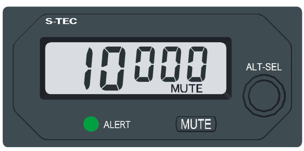
16 3.0 Overview 3.1 Theory of Operation The Altitude Selector/Alerter (ASA) reads the Altimeter's altitude information from the Altimeter's altitude encoder output and baro correction voltage output. The pilot entered target altitude and baro corrected altitude are then transmitted to the autopilot via a dedicated digital interface (RS-422). The interfacing autopilot performs all altitude functions such as altitude hold, vertical speed, and altitude capture. As the aircraft altitude approaches the selected target altitude, the ASA emits a series of tones, voice annunciations, and visual cues to indicate approach to target altitude as well as subsequent capture, and departure from captured altitude. 3.2 Quick Reference Altitude Select Display Visual Altitude ALERT Indicator ALT-SEL Knob Outer Ring - 1,000 ft Inner Ring ft Aural Annunciation "MUTE" Engage Switch Fig Altitude Selector / Alerter Quick Reference 3.3 Important Points to Remember: 1. Rotate ALT-SEL knob to set target altitude following initial self-test. 2. Push MUTE to enable or disable the aural alert annunciations. 3. Push the ALT-SEL Knob to activate and deactivate the altitude target. 1st Ed, 1st Rev: September 26,
17 3.4 Features and Functions Self Test (Power Up) When power is applied to the Altitude Selector / Alerter, the system will conduct an internal self test of the computer electronic elements, the display, the alert indicator and the altitude alerter audio tone (a two tone "chime"). Subsequently, a dash will translate across the display until the barometric altitude has been acquired. Successful power up is indicated by the display of five constant dashes on the altitude selector readout after completion of the test cycle Altitude (ALT - SEL) Select Function The ALT-SEL switch has two functions. The first function is to select the desired altitude by rotating the selector knob. The outer concentric knob increments/decrements the target altitude in thousands of feet, while the inner concentric knob increments/decrements the target altitude in hundreds of feet. The second function is to push the ALT-SEL knob which cancels the selected target altitude, the voice annunciations, the aural tone, and the visual alert while displaying dashes on the display panel. A subsequent push of the ALT-SEL knob will reinstate the altitude target and both the visual alert and the aural alert capabilities (if previously selected) Altitude Read Out When the display shows dashes and either the inner or outer ALT-SEL knob is rotated one knob click, the alerter will display the current altitude. Subsequent rotation of the ALT-SEL knob will increment or decrement the target altitude depending on the direction of knob rotation Altitude Alert (MUTE) Button The MUTE button enables or disables the voice and tone functions of the ASA. When the display shows dashes and a target altitude is entered, the aural alert will automatically be armed. A subsequent push of the MUTE button will disable / enable the aural tone output Altitude Alert As the aircraft moves within 1000 ft +/-100 ft. (+/-10 ft. with ADAHRS) of the selected target altitude, the altitude ALERT indicator will be lit and "1000 TO GO" will be annunciated by voice. The ALERT indicator will remain active (lit) until the barometric altitude is within 200 ft. +/-100 ft. (+/-10 ft. with ADAHRS) of the selected altitude at which point the ALERT indicator will turn off and "200 TO GO" will be annunciated by voice. At altitude capture, the ALERT indicator will flash for 2 seconds and "ALTITUDE" will be annunciated by voice st Ed, 1st Rev: September 26, 2003
18 3.4.5 Altitude Alert (Cont'd) After altitude capture, if the barometric altitude deviates from the selected altitude by +/-200 ft., the ALERT indicator will be activated (LIT) and the audio alert ("ding dong") will chime followed by "CHECK ALTITUDE." The ALERT indicator will be active until a deviation of 1000 ft. is achieved or the barometric altitude returns to within the +/-200 ft. band Setup Mode The Altitude Selector / Alerter includes a Setup Mode. This software driven mode enables the installer to make initial display and volume adjustments utilizing four distinct setup modes. These include alert volume, voice volume, LCD backlight brightness and panel light brightness. The remaining three modes are used for viewing the revision level, display type, and barometric correction. With power off, the setup mode is entered by pushing in and holding the ALT-SEL knob. Apply power to the system and when the display indicates " ", immediately release the knob. The unit will display "ADJ", indicating the unit is entering the Adjust Mode. After the initial power up sequence (about 15 seconds), the Altitude Selector / Alerter will display "1A" indicating the first menu in the setup mode Revision Level The revision level is the first setup mode entered after initial power up and will display the Altitude Selector / Alerter's current software revision level. After entering this mode, the LCD display indicates "1AXX". 1A indicates that this is the first adjust menu and XX highlights the current software revision level (01 to 99). During this mode, rotating the outer knob right or left will select the next or previous setup mode, while the inner knob rotation has no effect. Pressing the ALT-SEL knob takes the unit out of the setup mode and saves all the setup changes Alert Volume The alert volume is the second menu in the setup mode and enables the user to adjust the volume of the two-tone alert. After entering this mode, the LCD display indicates "2AXXX". 2A indicates that this is the second adjust menu and XXX indicates the current volume level. The volume level is displayed from in increments of 10 with 0 the lowest and 100 the highest. During this mode, rotating the outer knob right or left will select the next or previous setup mode, while rotation of the inner knob left or right will increase or decrease the volume. Pressing ALT-SEL takes the unit out of the setup mode and saves all the setup changes. 1st Ed, 1st Rev: September 26,
19 Voice Volume Voice volume is the third menu in the setup mode and enables the user to adjust the volume of the voice annunciations. After entering this mode, the LCD display indicates "3AXXX". The 3A indicates that this is the third adjust menu and XXX indicates the current volume level. The volume level is displayed from in increments of 10 with 0 the lowest and 100 the highest. During this mode, rotating the outer knob right or left will select the next or previous setup mode, while rotation of the inner knob left or right will increase or decrease the volume. Pressing the ALT-SEL knob takes the unit out of the setup mode and saves all the setup changes LCD Backlight Brightness LCD Backlight Brightness is the fourth menu in the setup mode and enables the user to adjust the brightness of the LCD backlight. After entering this mode, the LCD display indicates "4AXXX". 4A indicates that this is the fourth adjust menu and XXX indicates the current brightness level. The brightness level is displayed from in increments of 10 with 0 the lowest and 100 the highest. During this mode, rotating the outer knob right or left will select the next or previous setup mode, while rotation of the inner knob left or right will increase or decrease the brightness. Pressing the ALT-SEL knob takes the unit out of the setup mode and saves all the setup changes Panel Light Brightness Panel Light Brightness is the fifth menu in the setup mode and enables the user to adjust the brightness of the Panel Lights. After entering this mode, the LCD display indicates "5AXXX". 5A indicates that this is the fifth adjust menu and XXX indicates the current brightness level. The brightness level is displayed from in increments of 10 with 0 the lowest and 100 the highest. During this mode, rotating the outer knob right or left will select the next or previous setup mode, while rotation of the inner knob left or right will increase or decrease the brightness. Pressing the ALT-SEL knob takes the unit out of the setup mode and saves all the setup changes Display Type Display Type is the sixth menu in the setup mode. After entering this mode, the LCD display indicates "6A X". 6A indicates that this is the sixth adjust menu and X indicates either a 0 or 1. The 0 is for normal display (5 V drive) and 1 is for alternate display (17 V drive). However, there are no user adjustments as these settings are made at the factory. During this mode, rotating the outer knob right or left will select the next or previous setup mode, while rotation of the inner knob has no effect. Pressing the ALT-SEL knob takes the unit out of the setup mode and saves all the setup changes st Ed, 1st Rev: September 26, 2003
20 Barometric Correction Barometric Correction is the seventh menu in the set-up mode. Barometric Correction, derived from the analog Baro Correction input, is calibrated by the pilot. After entering this mode, the LCD display indicates "XXYY". XX indicates inches of Mercury (28" - 30") and YY indicates tenths of inches of Mercury (.00" -.99"). To calibrate the correction input, set the baro on the Interfacing Altimeter to Rotate the inner knob on the ASA until the display shows If RS-422 data is being used, the display will show "RS-422" and no calibration is necessary. Rotating the outer knob right or left will select the next or previous setup mode. Pressing the ALT-SEL knob takes the unit out of the setup mode and saves all the setup changes. 1st Ed, 1st Rev: September 26,
21 Page Intentionally Blank 3-8 1st Ed, 1st Rev: September 26, 2003
22 SECTION 4 OPERATING PROCEDURES 1st Ed, 1st Rev: September 26,
23 Page Intentionally Blank 4-2 1st Ed, 1st Rev: September 26, 2003
 The Altitude Selector / Alerter System is coupled to the autopilot by use of the VS and ALT switches on the autopilot programmer.")
24 4.0 Operating Procedures 4.1 Operation With Autopilot (S-TEC 55X / 550) The Altitude Selector / Alerter System is coupled to the autopilot by use of the VS and ALT switches on the autopilot programmer. For Altitude Preselect, set the desired altitude on the Altitude Selector/ Alerter then simultaneously depress both the VS and ALT switch buttons on the autopilot programmer. The autopilot mode annunciator will display VS, ALT, and a VS value (example 500 FPM), indicating that the autopilot is operating in VS mode with altitude armed for the altitude intercept. The aircraft will then intercept the target altitude and the autopilot VS annunciator will extinguish leaving the autopilot in altitude hold mode (ALT). If no target altitude is set, the autopilot will not accept pilot activation of the "dual mode" VS and ALT. Only the VS mode will be engaged if a dual mode operation is attempted with no target altitude set. 4.2 Lost Altitude Data Anytime the Altitude Selector / Alerter is in use and Altitude data or the RS-422 link is lost, the target altitude will be replaced by a FAIL indication followed by a tone and lockout of the ALT-SEL knob. This action informs the pilot that a malfunction has occurred and the selected target altitude is no longer displayed or attainable by using the Altitude Selector / Alerter. If the autopilot is in "Dual Mode" (ALT and VS selected on the autopilot), the autopilot will revert to "VS" mode because there no longer is a valid target. If altitude data or the RS-422 link is restored during the flight, the encoded altitude will display dashes instead of the FAIL indication. The Altitude Selector / Alerter can now be used again, if desired. Fig Altitude Selector / Alerter Fail Indication 1st Ed, 1st Rev: September 26,
25 +1000 FT "Altitude 1000 to go" "Altitude 200 to go" One Two-Tone and "Check Altitude" ALERT LED ON STEADY IN THESE REGIONS +200 FT 0FT -200 FT "Altitude" SELECTED ALTITUDE ALERT LED FLASHES FOR 2 SECONDS AT CAPTURE FT "Altitude 200 to go" "Altitude 1000 to go" One Two-Tone and "Check Altitude" ALERT LED ON STEADY IN THESE REGIONS Fig Altitude Selector / Alerter Annunciation Flight Profile 4.3 Pre-Flight Procedures The following pre-flight procedure provides an operational test of the entire system, including the altimeter, the Altitude Selector / Alerter (ASA) and the autopilot. A successful test is indicated by the autopilot switching from VS Mode to ALT Hold Mode as the selected altitude is matched to field elevation. 1. Autopilot Master Switch - ON 2. Altitude Selector / Alerter Power - ON (If a separate switch) 3. Insure Encoding Altimeter or EFIS - ON. NOTE: If the Altitude Selector / Alerter is not receiving a valid signal, the ASA display will show FAIL followed by a chime. A period of time should be allowed for the Encoding Altimeter or EFIS to initialize. 4. Set altimeter to local altimeter setting or field elevation, as appropriate. 5. Altitude Selector / Alerter - A. The self test cycle is complete when dashes cease rotating st Ed, 1st Rev: September 26, 2003
26 B. Rotate the ALT-SEL input knob to set the altitude ft. higher than the indicated altitude on the Altimeter. 6. Autopilot - When autopilot indicates ready "RDY." A. Engage HDG Mode. B. Simultaneously depress VS and ALT switches on the autopilot programmer computer (VS and ALT annunciations will both illuminate). C. Rotate the altitude selector knob CCW to change selected altitude to match field elevation. VS annunciation on the autopilot programmer computer should extinguish when the ALT-SEL setting on the Altitude Selector/Alerter is within 100 ft. of the indicated altitude on the altimeter and has remained unchanged for 3 seconds. Extinguishing of the VS annunciation with the ALT remaining on indicates the altitude hold mode has been engaged. 7. Disengage Autopilot - Adjust Altitude Selector/Alerter for desired altitude to be used after takeoff and during climb out. 8. Conduct autopilot preflight per the FAA/DAS approved Pilots Operating Handbook and Airplane Flight Manual Supplement for the autopilot system installation. 4.4 In-Flight Procedures 1. Ensure Encoding Altimeter is ON (with an adequate warmup). NOTE: Adequate warmup is indicated by rotating the small knob. When all dashes are displayed, one click verifies that the displayed altimeter matches the Encoding Altimeter's altitude within 100 ft. 2. Check baro setting, adjust as necessary. 3. Select desired target altitude. 4. For autopilot coupling, simultaneously depress the VS and ALT switches on the autopilot programmer computer. This will engage the VS modeand arm the altitude hold mode. Select the desired vertical speed on the autopilot programmer. Extinguished VS indicates altitude capture. 5. The pilot can level off at an intermediate altitude on the way to the target altitude, if desired, by manually pressing the ALT button on the autopilot. The climb/descent can be resumed by pressing ALT and VS buttons simultaneously. The desired vertical speed must be re-selected at this time. 1st Ed, 1st Rev: September 26,
27 NOTE: As the aircraft approaches the target altitude, the vertical speed closure rate will be automatically reduce for a smooth capture. NOTE: Pressing the ALT-SEL knob will erase the displayed altitude and the unit will annunciate dashes. Pressing the knob again, will cause the previously displayed target to reappear. With dashes displayed, rotating either knob oneclick will cause the displayed altitude to synchronize with the existing aircraft altitude. Rotating the knobs further will permit the selection of a new altitude. NOTE: If the wrong VS polarity (+/-) is selected to capture a target altitude, the aircraft will respond as commanded but will flash the VS Display on the autopilot to alert the pilot of the error. Example: The pilot wishes to climb to an altitude above the aircraft and selects a negative VS command (in this case -500 FPM VS). The display (VS -5) will continuously flash to alert the pilot of the incorrect VS command. 4.5 Emergency Procedures The Altitude Selector / Alerter provides only data information to the autopilot and cannot contribute to an autopilot malfunction. If for any reason, the ASA does not function properly, push the ALT-SEL knob to disable the altitude target and the aural and visual indications. This will completely remove the Altitude Selector / Alerter from the autopilot system. Do not attempt further use of the ASA until the fault has been corrected. The Altitude Selector / Alerter, powered by the autopilot circuit breaker, is a low power device which is essentially dormant unless actually in use (by selection of the VS and ALT modes on the autopilot simultaneously). NOTE: The SA-200 can only detect invalid encoder states and loss of encoder power st Ed, 1st Rev: September 26, 2003
28 SECTION 5 APPENDICES 1st Ed, 1st Rev: September 26,
29 Page Intentionally Blank 5-2 1st Ed, 1st Rev: September 26, 2003
30 Specifications Altitude Selector/Alerter Power required Weight Dimensions TSO 14/28 VDC (Automatically selected in ASA) 0.62 lbs 1.60 x 3.42 x 5.59 in. C9c 1st Ed, 1st Rev: September 26,
31 Page Intentionally Blank 5-4 1st Ed, 1st Rev: September 26, 2003
32 SECTION 6 GLOSSARY 1st Ed, 1st Rev: September 26,
33 Page Intentionally Blank 6-2 1st Ed, 1st Rev: September 26, 2003
34 6.0 Glossary Term ALT ASA BARO CCW CW DAS ED FAA FPM FT HDG IN. LBS POH SEL VDC VS Meaning Altitude Altitude Selector Alerter Barometric Counter Clockwise Clockwise Designated Alteration Station Edition Federal Aviation Administration Feet Per Minute Feet Heading Inches Pounds Pilot Operating Handbook Select Volts Direct Current Vertical Speed 1st Ed, 1st Rev: September 26,
35 Page Intentionally Blank 6-4 1st Ed, 1st Rev: September 26, 2003

36 Information contained in this document is subject to change without notice S-TEC. All rights reserved. Printed in the United States of America. S-TEC and the S-TEC logo are registered trademarks of S-TEC. Notice: Contact S-TEC Customer Support at for a Service Repair Order (SRO) number prior to the return of any component for any reason. One S TEC Way Municipal Airport Mineral Wells, TX Tel: Fax: S TEC PN 87118
Revision Number Revision Date Insertion Date/Initials 1 st Ed. Oct 26, 00 2nd Ed. Jan 15, 08
 List of Effective Pages * Asterisk indicates pages changed, added, or deleted by current revision. Retain this record in front of handbook. Upon receipt of a Record of Revisions revision, insert changes
S-TEC. Pilot s Operating Handbook
 S-TEC Pilot s Operating Handbook List of Effective Pages * Asterisk indicates pages changed, added, or deleted by current revision. Retain this record in front of handbook. Upon receipt of a Record of
S-Tec System 55X Autopilot w/ Altitude Selector/Alerter
 Cirrus Design Section 9 Pilot s Operating Handbook and FAA Approved Airplane Flight Manual Supplement For S-Tec System 55X Autopilot w/ Altitude Selector/Alerter When the S-Tec System Fifty Five X (55X)
2100 Autopilot Programmer/Computer PN Software Mod Code L or Later WAAS Capable Pilot s Operating Handbook
 2100 Autopilot Programmer/Computer PN 01304 Software Mod Code L or Later WAAS Capable Pilot s Operating Handbook NAV VS 500 ALT 12 5 00 List of Effective Pages * Asterisk indicates pages changed, added,
S-TEC. Pilot s Operating Handbook
 S-TEC Pilot s Operating Handbook List of Effective Pages * Asterisk indicates pages changed, added, or deleted by current revision. Retain this record in front of handbook. Upon receipt of a Record of
S-Tec System 55 Autopilot
 Cirrus Design Section 9 Pilot s Operating Handbook and FAA Approved Airplane Flight Manual Supplement for S-Tec System 55 Autopilot When the S-Tec System 55 Autopilot is installed in the Cirrus Design,
P/N 135A EASA Approved: June 23, 2011 Section 9 Initial Release Page 1 of 22
 EASA APPROVED AIRPLANE FLIGHT MANUAL SUPPLEMENT FOR S-TEC SYSTEM 30 AUTOPILOT INTEGRATED IN THE LIBERTY XL2 SERIES AIRCRAFT Serial No: Registration No: When installing the S-TEC System 30 Autopilot Integrated
MOONEY AIRPLANE COMPANY, INC. LOUIS SCHREINER FIELD KERRVILLE, TEXAS FAA APPROVED: AIRPLANE FLIGHT MANUAL SUPPLEMENT MOONEY M20M, M20R, M20TN
 MOONEY AIRPLANE COMPANY, INC. LOUIS SCHREINER FIELD KERRVILLE, TEXAS 78028 FAA APPROVED AIRPLANE FLIGHT MANUAL SUPPLEMENT FOR MOONEY WITH S -TEC SYSTEM 55X, TWO AXIS, AUTOPILOT INSTALLED MODEL NO. REG.
Cirrus SR20/22 Aircraft with Cirrus Perspective Avionics. Pilot s Operating Handbook
 Cirrus SR20/22 Aircraft with Cirrus Perspective Avionics Pilot s Operating Handbook List of Effective Pages * Asterisk indicates pages changed, added, or deleted by current revision. Page No. Issue Retain
CESSNA MODEL 182T NAV III AVIONICS OPTION - KAP 140 AUTOPILOT Serials and thru and thru
 CESSNA MODEL 182T NAV III AVIONICS OPTION - Serials 18281228 and 18281318 thru 18281868 and 18281870 thru 18281875 BENDIX/KING KAP 140 2 AXIS AUTOPILOT SERIAL NO. REGISTRATION NO. This supplement must
Multifunction Altimeter/Variometer AV1
 Multifunction Altimeter/Variometer AV1 Revision#3.0, 21/11/2014 For firmware version 2.2 Page intentionally left blank SECTIONS MECHANICAL INSTALLATION ELECTRICAL INSTALLATION USE OF THE INSTRUMENT INSTRUMENT
ltitudealert Mini v2.1 Page 1
 ltitudealert Mini Hello, and thank you for purchasing AltitudeAlert! AltitudeAlert Mini is the first altitude preselect and alerting app for the iphone. Please take a moment and review this User Guide
OPERATION INSTRUCTIONS
 TAS 1000 OPERATION INSTRUCTIONS DOCUMENT 1000-401 DATE: April 29/2011 REV. D PLEASE READ INSTRUCTIONS COMPLETELY BEFORE PROCEEDING WITH INSTALLATION Instrument Corporation P.O. Box 122 Fort Erie, Ontario
CHAPTER 4 AUTOMATIC FLIGHT CONTROLS
 CHAPTER 4 AUTOMATIC FLIGHT CONTROLS CONTENTS Page GENERAL... 4-1 SYSTEM DESCRIPTION... 4-4 Lateral Modes... 4-4 Vertical Modes... 4-9 Autopilot Operation... 4-15 CONTROLS AND INDICATIONS... 4-22 Flight
SAI-340 Pilot Guide Osuna Road NE Suite 711 Albuquerque, NM Rev 3
 SAI-340 Pilot Guide 306184-00 Rev 3 This document and the information contained herein is the propriety data of SANDIA aerospace Corporation. No part of this document may be transmitted, reproduced, or
5 Function Indicator. Outside Air Temperature (C) Outside Air Temperature (F) Pressure Altitude Density Altitude Aircraft Voltage STD TEMP SL 15000
 Outside Air Temperature (F) Pressure Altitude Density Altitude Aircraft Voltage STD TEMP SL 15000") 5 Function Indicator +20 +40-5000 STD TEMP SL 15000 Outside Air Temperature (C) Outside Air Temperature (F) Pressure Altitude Density Altitude Aircraft Voltage 427 HILLCREST WAY REDWOOD CITY, CA 94062
5 Function Indicator +20 +40-5000 STD TEMP SL 15000 Outside Air Temperature (C) Outside Air Temperature (F) Pressure Altitude Density Altitude Aircraft Voltage 427 HILLCREST WAY REDWOOD CITY, CA 94062
ECHO MANUAL WARNING. L B A ltim e te rs. ECHO is a trademark of LB Altimeters, Denmark
 ECHO MANUAL L B A ltim e te rs ECHO is a trademark of LB Altimeters, Denmark LB Altimeters operates a policy of continuous development Therefore, we reserve the right to make changes and improvements to
SECTION 6-16 FLIGHT INSTRUMENTS
 SECTION 6-16 SYSTEMS DESCRIPTION Index Page Pitot-Static System... 6-16-2 Airspeed Indicator... 6-16-4 Vertical Speed Indicator... 6-16-4 Instantaneous Vertical Speed Indicator IVSI (Optional)... 6-16-5
DBI version 002 User Manual US version Free Balloon Flight Instrument
 DBI version 002 User Manual US version Free Balloon Flight Instrument DBI 002 User Manual issue C7, 2005-05-25 Page 1/29 Safety The manufacturer has designed this instrument to be safe when operated. Do
For Microsoft Flight Simulator FriendlyPanels. All right reserved
 FriendlyPanels Software For Microsoft Flight Simulator 2004 2006 FriendlyPanels. All right reserved TWO CESSNA 675 AND 675 AMPHIBIAN AIRCRAFTS TWO DIFFERENT GPS EQUIPMENTS THREE LIVERIES FOR EACH AIRCRAFT
STX 165 Operation. Data Knob Enter Pushbutton. Power/Mode Control. Select Knob Ident Pushbutton. VFR Pushbutton
 STX 165 Operation The STX 165 is a Mode C transponder capable of transmitting 4076 different codes in response to ground radar interrogations. All operations of the STX 165 are controlled through the front
ltitudealert for ipadv2
 ltitudealert for ipadv2 Hello, and thank you for purchasing AltitudeAlert for ipad! AltitudeAlert is the first altitude preselect and alerting app for the ipad. Please take a moment and review this User
AIR CONDITIONING AND PRESSURIZATION CONTROLS AND INDICATORS
 AIR CONDITIONING AND PRESSURIZATION CONTROLS AND INDICATORS Air conditioning control panel 1 MIN MAX Page 1 Air conditioning control panel 2 MIN MAX Page 2 Air conditioning control panel 3 MIN MAX Page
DT 630 ALTIMETER, BAROMETER AND COMPASS WATCH OPERATING INSTRUSTIONS
 DT 630 ALTIMETER, BAROMETER AND COMPASS WATCH OPERATING INSTRUSTIONS Overview:--- Positive or Negative Icon Barometric Trend Indicator SELECT Low Battery Indicator AM/FM Indicator Daily Alarm Indicator
Stability Augmentation System and Autopilot. Pilot s Operating Handbook
 Stability Augmentation System and Autopilot Pilot s Operating Handbook List of Effective Pages * Asterisk indicates pages changed, added, or deleted by current revision. Page No. Issue Retain this record
Altimeter and Compass Watch Instruction Manual
 Altimeter and Compass Watch Instruction Manual Overview Figure 1 LCD display description Features Hour, minute, second, year, Auto calendar 12/24 hour format display month, day, day of week Daily alarm
Alpha Systems AOA th Ave. N.W. Ramsey, MN Customer Support
 Alpha Systems AOA 6180 140 th Ave. N.W. Ramsey, MN 55303 Customer Support 763.506.9990 aoa@depotstar.com The information contained in this manual is for reference only. If any information contained herein
UBEC 1AT. AUTO TANK Fill System Installation, Operation, & Setup Instructions
 Document Number: XE-ATA5PM-R1A UBEC 1AT AUTO TANK Fill System 08899155 Installation, Operation, & Setup Instructions Rev170906-EB-FRC PHYSICAL: 1302 WEST BEARDSLEY AVE ELKHART, IN 46514 WWW.ELKHARTBRASS.COM
Alpha Systems AOA th Ave. N.W. Ramsey, MN Customer Support
 Alpha Systems AOA 6180 140 th Ave. N.W. Ramsey, MN 55303 Customer Support 763.506.9990 aoa@depotstar.com The information contained in this manual is for reference only. If any information contained herein
F11 OPERATING MANUAL F11 OPERATING MANUAL
 F11 OPERATING MANUAL 2002 Design, 2014 1 CONTENTS NOTICES...2 INITIAL ACTIVATION...3 FULL LCD...3 GENERAL FEATURES & DISPLAYS...5 INTERACTIVE CONTROL CONSOLE...6 OPERATING MODE STRUCTURE...6 OPERATION
Roller AC Servo System
 Safely Instruction Roller AC Servo System HMI-15 User Manual Please read this manual carefully, also with related manual for the machinery before use the controller. For installing and operating the controller
Copyright 2004 by the Thomas G. Faria Corporation, Uncasville CT No part of this publication may by reproduced in any form, in an electronic
 Copyright 2004 by the Thomas G. Faria Corporation, Uncasville CT No part of this publication may by reproduced in any form, in an electronic retrieval system or otherwise, without the prior written permission
VISO Manual. LARSEN & BRUSGAARD Mosevej Kirke Hyllinge, Denmark Phone: Fax:
 VISO Manual LARSEN & BRUSGAARD Mosevej 3 4070 Kirke Hyllinge, Denmark Phone: +45 4648 2480 Fax: +45 4648 2490 E-mail: L-and-B@L-and-B.dk WARNING! FAILURE TO FOLLOW ALL WARNINGS, INSTRUCTIONS, AND REQUIRED
1811G/H PITOT-STATIC TEST SET
 1811G/H PITOT-STATIC TEST SET USER INSTRUCTION MANUAL M/N: 1811G/H, P/Ns: 101-00165 101-00168 101-00169 Doc. P/N: 56-101-00165_00168_00169 Revision C December 9, 2014 BARFIELD, INC. Corporate Headquarters
Noise Abatement Takeoff 1 Close In Profile
 PF Duties Captain: Advance thrust to 70% N1 (Allow Engines to stabilize) Noise Abatement Takeoff 1 Close In Profile Flaps Increase Speed to Vref 30 +80kts Climb Checklist Push N1 Button to set Takeoff
Pitot-Static System - Inspection/Check ICA Supplement
 AIRCRAFT DIVISION WICHITA, KANSAS 67277 Pitot-Static System - Inspection/Check ICA Supplement MODEL NO: 680A SUPPLEMENT NO: ICA-680A-34-00001 SUPPLEMENT DATE: 1/22/2016 Cessna Aircraft Company Form 2261
TL-3524 USER`S MANUAL
 TL-3524 USER`S MANUAL TL TL Airport, Building 125, Hradec Kralove 503 41, Czech Republic Copyright 2003, TL Non TSO approved Copyright 2003-2006 TL All Rights Reserved Except as expressly provided below,
WARNING! FAILURE TO FOLLOW ALL WARNINGS, INSTRUCTIONS, AND REQUIRED PROCEDURES MAY RESULT IN SERIOUS INJURY AND DEATH.
 PROTRACK II Manual Every technical device can fail. So everything imaginable can happen with the PROTRACK II, including, but not limited to: displaying a status which is not true, failing to function,
Pilot s Operating Handbook
 Pilot s Operating Handbook List of Effective Pages * Asterisk indicates pages changed, added, or deleted by current revision. Page No. Issue Retain this record in front of handbook. Upon receipt of a Record
Fokker 50 - Air Conditioning & Pressurization
 AIR CONDITIONING General Pressure regulated engine bleed-air is cooled and temperature regulated in two air conditioning packs. The temperature-regulated airflow can be mixed with recirculated cabin air.
OPERATION AND INSTALLATION MANUAL
 AP46 Autopilot OPERATION AND INSTALLATION MANUAL www.tmq.com.au TMQ AP46 Autopilot Page 1 of 34 Ver1.0 07/03/2007 This page is Blank TMQ AP46 Autopilot Page 2 of 34 Ver1.0 07/03/2007 WARNING!...4 INTRODUCTION...5
WARNING! Jump Number Main Window Exit Altitude Alti-Meter Mode Deployment Altitude Speed-Meter Mode...
 VISO II Manual LARSEN & BRUSGAARD Mosevej 3 4070 Kirke Hyllinge, Denmark Phone: +45 4648 2480 Fax: +45 4648 2490 E-mail: L-and-B@L-and-B.dk WARNING! FAILURE TO FOLLOW ALL WARNINGS, INSTRUCTIONS, AND REQUIRED
Stand-Alone Bubble Detection System
 Instruction Sheet P/N Stand-Alone Bubble Detection System 1. Introduction The Bubble Detection system is designed to detect air-bubble induced gaps in a bead of material as it is being dispensed. When
A4s Operation Manual
 A4s Operation Manual Safety Instruction Please read this manual carefully, also with related manual for the machinery before use the controller. For installing and operating the controller properly and
SR22 Airplane Flight Manual (AFM) Temporary Change
 Temporary Change") Cirrus Design TPOH AFM Temporary Change Airplane Flight Manual (AFM) Temporary Change Information in this Temporary Change adds to, supersedes, or deletes information in the basic Pilot s Operating Handbook.
Cirrus Design TPOH AFM Temporary Change Airplane Flight Manual (AFM) Temporary Change Information in this Temporary Change adds to, supersedes, or deletes information in the basic Pilot s Operating Handbook.
Manual Weighingblock VB2 series and Uniscale
 Manual Weighingblock VB2 series and Uniscale Note: At page 8 in this manual you will find a short form instruction. Normally the only instruction shipped together with the Scale. Overview different ranges.
Scoreboard Operator s Instructions MPC Control
 Scoreboard Operator s Instructions MPC Control Some features on the keyboard overlay may not be included on the particular model being operated. Since 1934 Retain this manual in your permanent files 1/21/2011
A4 Operation Manual. Fig.1-1 Controller Socket Diagram
 A4 Operation Manual Safety Instruction Please read this manual carefully, also with related manual for the machinery before use the controller. For installing and operating the controller properly and
Race Screen: Figure 2: Race Screen. Figure 3: Race Screen with Top Bulb Lock
 Eliminator Competition Stand Alone Mode - Instruction Manual Main Menu: After startup, the Eliminator Competition will enter the Main Menu. Press the right/left arrow buttons to move through the menu.
ALT-1. Introduction. Precision Encoding Altimeter and Vertical speed indicator (VSI) Operating Manual English 1.09
 Operating Manual English 1.09") ALT-1 Precision Encoding Altimeter and Vertical speed indicator (VSI) Operating Manual English 1.09 Introduction The ALT-1 is a 2 1/4 instrument that contains a precision encoding altimeter and a wide
ALT-1 Precision Encoding Altimeter and Vertical speed indicator (VSI) Operating Manual English 1.09 Introduction The ALT-1 is a 2 1/4 instrument that contains a precision encoding altimeter and a wide
SUPPLEMENT SEPTEMBER 2010 HIGH ALTITUDE TAKEOFF AND LANDING (ABOVE 14,000 FEET PRESSURE ALTITUDE) MODEL AND ON 68FM-S28-00 S28-1
 MODEL AND ON 68FM-S28-00 S28-1") MODEL 680 680-0001 AND ON HIGH ALTITUDE TAKEOFF AND LANDING (ABOVE 14,000 FEET PRESSURE ALTITUDE) COPYRIGHT 2010 CESSNA AIRCRAFT COMPANY WICHITA, KANSAS, USA 15 SEPTEMBER 2010 S28-1 SECTION V - SUPPLEMENTS
MODEL 680 680-0001 AND ON HIGH ALTITUDE TAKEOFF AND LANDING (ABOVE 14,000 FEET PRESSURE ALTITUDE) COPYRIGHT 2010 CESSNA AIRCRAFT COMPANY WICHITA, KANSAS, USA 15 SEPTEMBER 2010 S28-1 SECTION V - SUPPLEMENTS
VI.A-E. Basic Attitude Instrument Flight
 References: FAA-H-8083-3; FAA-8083-3-15 Objectives Key Elements Elements Schedule Equipment IP s Actions SP s Actions Completion Standards The student should develop knowledge of the elements related to
PART 5 - OPTIONS CONTENTS 5.1 SYSTEM EXPANSION 5-3
 PART 5 - OPTIONS CONTENTS Para Page 5.1 SYSTEM EXPANSION 5-3 5.2 SENSORS 5-3 5.2.1 Trim Angle Sensor 5-3 5.2.2 Mast Rotation Sensor 5-3 5.2.3 Heel Angle Sensor 5-3 5.2.4 Barometric Pressure Sensor 5-3
AHE58/59 AC Servo System
 AHE58/59 AC Servo System HMI-12 User Manual Safely INstruction Please read this manual carefully, also with related manual for the machine head before use. For perfect operation and safety, installing
PS-425 Pitot-Static/Air Data Tester
 PS-425 Pitot-Static/Air Data Tester OPERATION AND MAINTENANCE MANUAL Preston Pressure LLC 580-286-3161 prestonpressure.com Revision 1, February 16, 2011 PRESTON PRESSURE LLC PS-425 USER AND MAINTENANCE
MODEL 6600 Rev. B4 USER'S MANUAL LAVERSAB INC., 505 GILLINGHAM LANE. SUGAR LAND TX (281) FAX: (281)
 FAX: (281)") MODEL 6600 Rev. B4 USER'S MANUAL LAVERSAB INC., 505 GILLINGHAM LANE. SUGAR LAND TX 77478 (281) 325-8300 FAX: (281) 325-8399 Email: aservice@laversab.com Document Number : 9051 REV B4 Date: June 07, 2011.
MODEL 6600 Rev. B4 USER'S MANUAL LAVERSAB INC., 505 GILLINGHAM LANE. SUGAR LAND TX 77478 (281) 325-8300 FAX: (281) 325-8399 Email: aservice@laversab.com Document Number : 9051 REV B4 Date: June 07, 2011.
MODEL 9875 STADIUM BASEBALL SCOREBOARD. Instruction Manual
 UNITEC MANUFACTURING DIVISION MODEL 9875 STADIUM BASEBALL SCOREBOARD (WITH INNING BY INNING SCORING) Instruction Manual Mailing Address: PO Box 260, Yorkville, NY 13495-0260 Plant Address: 34 Main Street,
Courseware Sample F0
 Electric Power / Controls Courseware Sample 85303-F0 A ELECTRIC POWER / CONTROLS COURSEWARE SAMPLE by the Staff of Lab-Volt Ltd. Copyright 2009 Lab-Volt Ltd. All rights reserved. No part of this publication
User Manual. asense VAV. CO 2 / temperature sensor with built-in general purpose controller
 Gas and Air Sensors User Manual asense VAV CO / temperature sensor with built-in general purpose controller General The IAQ-sensor product asense VAV is used to measure indoor air carbon dioxide concentration
BUBBLER CONTROL SYSTEM
 BUBBLER CONTROL SYSTEM Description: The HDBCS is a fully automatic bubbler system, which does liquid level measurements in water and wastewater applications. It is a dual air compressor system with, air
Manufactured by: AAA
 Manufactured by: AAA The Altitron Skydiving Altimeter is an advanced digital altimeter. It is designed to effectively improve safety and easily keep track of skydiving activity. It can be used as a mechanical
DAHER-SOCATA Customer Support. TBM700 - TBM850 - TBM900 Review of high altitude operations
 DAHER-SOCATA Customer Support TBM700 - TBM850 - TBM900 Review of high altitude operations 2014-008 September 24, 2014 Dear Owners, Operators and Network members, This Service Information is for general
SECTION 1 - GENERAL SECTION 2 - LIMITATIONS SECTION 3 - EMERGENCY PROCEDURES
 Beechcraft Bonanza Models. 35-33,35-A33,35-833,35-C33,35C33A, E33, E33A, E33C, F33, F33A. F33C, G33, A35, 835, C35, D35, E35, F35, G35,35R, H35, 535, K35, M35, N35, P35,S35, V35, V35A, V358,36, A36, A36TC
TEL/jlRE" Introduction. Display Features and Modes. Startup Procedure. Power-Up Procedure. Adjustment Modes
 TEL/jlRE" Introduction The Telaire 7001 CO 2 /T emperature monitor (shown in Fi gt u e 1 below) is an easy to use hand-held instnunent, which provides stable and highly accurate readings due to Telaire
XII.A-D. Basic Attitude Instrument Flight
 References: FAA-H-8083-3; FAA-8083-3-15 Objectives Key Elements Elements Schedule Equipment IP s Actions SP s Actions Completion Standards The student should develop knowledge of the elements related to
D OPERATION and MAINTENANCE MANUAL MILITARY ALTIMASTER MA-10 (30,000 foot COMPRESSED SCALE: FP-02093) January 3, 2008 REV 12
 January 3, 2008 REV 12") D-90046 OPERATION and MAINTENANCE MANUAL MILITARY ALTIMASTER MA-10 (30,000 foot COMPRESSED SCALE: FP-02093) January 3, 2008 REV 12 D-90046 Manual, Operation and Maintenance MA-10 Compressed Rev 12.doc
D-90046 OPERATION and MAINTENANCE MANUAL MILITARY ALTIMASTER MA-10 (30,000 foot COMPRESSED SCALE: FP-02093) January 3, 2008 REV 12 D-90046 Manual, Operation and Maintenance MA-10 Compressed Rev 12.doc
GO AROUND PNF 3.THRUST REDUCTION/ACCELERATION ALTITUDE 1.GO AROUND INITIATION 5.DIVERSION. 4.HOLD (missed approach) 2.
 2.") GO AROUND 1.GO AROUND INITIATION 3.THRUST REDUCTION/ACCELERATION ALTITUDE 5.DIVERSION 2.LATERAL GUIDANCE 4.HOLD (missed approach) A320 - Version 05 1. GO AROUND INITIATION Decision THRUST LEVERS. TOGA
GO AROUND 1.GO AROUND INITIATION 3.THRUST REDUCTION/ACCELERATION ALTITUDE 5.DIVERSION 2.LATERAL GUIDANCE 4.HOLD (missed approach) A320 - Version 05 1. GO AROUND INITIATION Decision THRUST LEVERS. TOGA
BUBBLER CONTROL SYSTEM
 BUBBLER CONTROL SYSTEM Description: The LDBCS is a fully automatic bubbler system, which does liquid level measurements in water and wastewater applications. It is a dual air compressor system with, air
Digitool Instruments AB DBI3 US User Manual Free Balloon Flight Instrument
 Digitool Instruments AB DBI3 US User Manual Free Balloon Flight Instrument Not Used DBI3 User Manual, Rev C, 9 Nov 2017 Page 2 of 29 Safety Digitool AB has designed this flight instrument to enable the
ENVIRONMENTAL CONTROL SYSTEM (ECS)
") ENVIRONMENTAL CONTROL SYSTEM (ECS) DESCRIPTION AND OPERATION The ECS system comprises the following subsystems: bleed air management, environmental control unit (ECU) temperature control air distribution
ENVIRONMENTAL CONTROL SYSTEM (ECS) DESCRIPTION AND OPERATION The ECS system comprises the following subsystems: bleed air management, environmental control unit (ECU) temperature control air distribution
Civil Air Patrol Auxiliary of the United States Air Force
 Mountain Flying Qualification Course Civil Air Patrol Auxiliary of the United States Air Force DENSITY ALTITUDE Pressure Altitude Pressure Altitude: Absolute altitude corrected for non-standard atmospheric
Latest 3D Technology for Speed + Distance & Heart Rate - Built in USB. 3D SENSOR FROM GERMANY MEASURES YOUR MOVEMENT ACCURATELY HEART RATE BELT
 PHRM20 Latest 3D Technology for Speed + Distance & Heart Rate - Built in USB. 3D SENSOR FROM GERMANY MEASURES YOUR MOVEMENT ACCURATELY EL/RESET ST/SP/+ MODE/SET LAP/SAVE/- HEART RATE BELT This unit is
CONTENTS STEER TO VANE MODE...
 CONTENTS GENERAL INTRODUCTION TO B&G NETWORK... 2 INTRODUCTION TO NETWORK PILOT... 3 SWITCHING THE NETWORK PILOT ON... 3 NETWORK PILOT DISPLAY UNIT... 4 NETWORK PILOT HAND-HELD CONTROLLER... 5 JOYSTICK
Operator: Save these instructions for future use!
 Pilot Gas Outlet: Located at outlet end of the valve Type of Gas Suitable for all domestic heating gases Pressure Rating: 1/2 lb. per sq. in. Pressure Regulator Adjust Range (Typical, See Control Label):
MODEL 6500 Rev. F4 USER'S MANUAL LAVERSAB INC., 505 GILLINGHAM LANE SUGAR LAND TX, (281) FAX: (281)
 FAX: (281)") MODEL 6500 Rev. F4 USER'S MANUAL LAVERSAB INC., 505 GILLINGHAM LANE SUGAR LAND TX, 77478 (281) 325-8300 FAX: (281) 325 8399 Email: aservice@laversab.com Document Number : 9014 REV.F4 Date: February 23,
MODEL 6500 Rev. F4 USER'S MANUAL LAVERSAB INC., 505 GILLINGHAM LANE SUGAR LAND TX, 77478 (281) 325-8300 FAX: (281) 325 8399 Email: aservice@laversab.com Document Number : 9014 REV.F4 Date: February 23,
Constant Pressure Inlet (CCN) Operator Manual
 Operator Manual") Constant Pressure Inlet (CCN) Operator Manual DOC-0125 Revision J 2545 Central Avenue Boulder, CO 80301-5727 USA C O P Y R I G H T 2 0 1 1 D R O P L E T M E A S U R E M E N T T E C H N O L O G I E S, I
Constant Pressure Inlet (CCN) Operator Manual DOC-0125 Revision J 2545 Central Avenue Boulder, CO 80301-5727 USA C O P Y R I G H T 2 0 1 1 D R O P L E T M E A S U R E M E N T T E C H N O L O G I E S, I
Auto.10 Automatic Flight-Description and Operation. General
 Auto.10 Automatic Flight-Description and Operation General The aircraft is equipped with an Automatic Flight System (AFS) for guidance from takeoff to landing. The two AFS flight control computers (FCC)
OPERATING INSTRUCTIONS FOR
 OPERATING INSTRUCTIONS FOR MODEL 2240LED www.sportablescoreboards.com 1 Table of Contents CONTROLLER DEFINITIONS... 3 COMMUNICATION CABLES... 4 CONNECTING A HARD WIRED CABLE:... 4 CONNECTING A WIRELESS
M2110P SMART PRESSURE GAUGE USER S MANUAL
 M2110P SMART PRESSURE GAUGE USER S MANUAL Meriam s M2110P Smart Pressure Gauge is a microprocessor-based pressure sensing device. The various ranges available provide measurement of differential (dry/dry
CircuFlow Quick Setup Guide
 CircuFlow 5200 Quick Setup Guide LB04.0001 Rev B 20140314 TABLE OF CONTENTS Setup Therapy Setup Gradient Mode Pressure Mode Lock Device Unlock Device Treatment 03 04 05 08 11 12 13 02 SETUP 01 01 Open
D OPERATION and MAINTENANCE MANUAL MILITARY ALTIMASTER MA-10 (12,000 foot LINEAR SCALE: FP-02096) April 8, 2013 REV L
 April 8, 2013 REV L") D-90073 OPERATION and MAINTENANCE MANUAL MILITARY ALTIMASTER MA-10 (12,000 foot LINEAR SCALE: FP-02096) April 8, 2013 REV L ALTI-2 PROPRIETARY Page 1 of 15 TABLE OF CONTENTS DESCRIPTION... 3 SPECIFICATION...
D-90073 OPERATION and MAINTENANCE MANUAL MILITARY ALTIMASTER MA-10 (12,000 foot LINEAR SCALE: FP-02096) April 8, 2013 REV L ALTI-2 PROPRIETARY Page 1 of 15 TABLE OF CONTENTS DESCRIPTION... 3 SPECIFICATION...
MicroTim XB. User Manual. Precision Digital Barometric Altimeter / Barometer / VSI. Document Revision 1.0 Firmware Version 3.0
 MicroTim XB Precision Digital Barometric Altimeter / Barometer / VSI User Manual Document Revision 1.0 Firmware Version 3.0 Table of Contents Table of Contents...2 1 General Operation...5 1.1 Altitude
5000TOC Sensor Standard Operating Procedure for TOC Calibration Conductivity Calibration Temperature Calibration Flow Rate Calibration
 Part No. 84468 5000TOC Sensor Standard Operating Procedure for TOC Calibration Conductivity Calibration Temperature Calibration Flow Rate Calibration This document contains proprietary information, which
Pressure and Density Altitude
 Pressure and Density Altitude Reference Sources Pilot s Handbook of Aeronautical Knowledge o Pages 9-1 to 9-4, Aircraft Performance o Pages 9-20 to 9-21, Density Altitude Charts Study Questions 1. Where
MODEL 6500 Rev. E USER'S MANUAL
 MODEL 6500 Rev. E USER'S MANUAL LAVERSAB INC., 505 GILLINGHAM LANE SUGAR LAND TX, 77478 (281) 325-8300 FAX: (281) 325 8399 Email: service@laversab.com Document Number : 9014 REV.E Date: June 6, 2005. WARRANTY
TR Electronic Pressure Regulator. User s Manual
 TR Electronic Pressure Regulator Page 2 of 13 Table of Contents Warnings, Cautions & Notices... 3 Factory Default Setting... 4 Quick Start Procedure... 5 Configuration Tab... 8 Setup Tab... 9 Internal
ICARUS Instruments, Inc. AltAlert 3070 Pilot's Operating Handbook
 ICARUS Instruments, Inc. AltAlert 3070 Pilot's Operating Handbook 1 Icarus Instruments, Inc. 7000 Carroll Avenue Takoma Park, MD USA 20912 301 891 0600 Fax 301 891 0666 Rev 1.0 September 1995 2 Table of
WATCH COLLECTION NG701 SERIES INSTRUCTION MANUAL
 WATCH COLLECTION NG701 SERIES INSTRUCTION MANUAL INTRODUCTION This watch features electronic sensors that measure outdoor conditions such as temperature, pressure, and altitude. The watch provides essential
ILS APPROACH WITH A320
 1. Introduction ILS APPROACH WITH A320 This document presents an example of an Instrument landing system (ILS) approach performed with an Airbus 320 at LFBO airport runway 32 left. This document does not
2. USER INSTRUCTION. Table of contents: Pg.1/14 N:\FAP-2000: LWP
 Pg.1/14 2. USER INSTRUCTION. Table of contents: 2.1 SHORT PANEL DESCRIPTION...... Pg.2 2.2 AUTOPILOT TAKE-OVER & MODE SELECTION....... Pg.3 2.3 AUTOPILOT FUNCTIONS....... Pg.3 2.4 THE SPECIAL FUNCTION
Dash8-200/300 - Warning Systems WARNING SYSTEMS CONTROLS AND INDICATORS. Page 1. Fast / Slow indicator and Stall Warning Test Switch
 WARNING SYSTEMS CONTROLS AND INDICATORS Fast / Slow indicator and Stall Warning Test Switch Page 1 Stick Pusher and Shaker Page 2 GPWS Controls and indicators Page 3 CENTER CONSOLE GPWS Controls and indicators
TABLE OF CONTENTS INTRODUCTION 3 SAFETY PRECAUTIONS 3 PACKAGE CONTENTS 4 DEVICE OVERVIEW 4 BUTTON OPERATION SUMMARY 5 BASIC OPERATION 6
 TABLE OF CONTENTS INTRODUCTION 3 SAFETY PRECAUTIONS 3 PACKAGE CONTENTS 4 DEVICE OVERVIEW 4 BUTTON OPERATION SUMMARY 5 BASIC OPERATION 6 CURRENT TIME MODE 7 FUNCTIONAL DISPLAY 7 WEATHER FORECAST FEATURE
Shearwater GF Computer
 Shearwater GF Computer DANGER This computer is capable of calculating deco stop requirements. These calculations are at best a guess of the real physiological decompression requirements. Dives requiring
GNX 20/21. Owner s Manual
 GNX 20/21 Owner s Manual March 2016 190-01659-00_0C All rights reserved. Under the copyright laws, this manual may not be copied, in whole or in part, without the written consent of Garmin. Garmin reserves
C1960. Multi-recipe profile recorder/controller. Measurement made easy
 ABB ME ASUREMENT & A NALY TI C S PROGR AMMING GU I DE I M/C1900 - FG REV. B C1960 Circular chart recorder/controller Multi-recipe profile recorder/controller Measurement made easy C1900 circular chart
OPERATIONS MANUAL PART A INSTRUCTIONS AND TRAINING REQUIREMENTS FOR THE AVOIDANCE OF CONTROLLED FLIGHT INTO TERRAIN AND POLICIES FOR THE USE OF GPWS
 PAGE: 1 Table of Contents A.GENERAL /CHAPTER 31. -...3 31. POLICIES FOR THE USE OF GPWS... 3 31.1 GPWS and Upset Training Requirements... 3 31.2 GPWS General... 3 31.3 Alerts and Warnings... 3 31.4 Levels
SCIENTIFIC DATA SYSTEMS, INC. Depth Tension Line Speed Panel. DTLS Manual
 SCIENTIFIC DATA SYSTEMS, INC. Depth Tension Line Speed Panel DTLS Manual This document contains proprietary information. Copyright 2015 Scientific Data Systems, Inc. All rights reserved. 1 Depth Tension
Flying The Embraer Brasilia (EMB-120)
") Flying The Embraer Brasilia (EMB-120) This section includes Pilot s Operating Handbook and Checklists. The POH section is first, followed by the Checklists. FOM: This section includes performance data
Flying The Embraer Brasilia (EMB-120) This section includes Pilot s Operating Handbook and Checklists. The POH section is first, followed by the Checklists. FOM: This section includes performance data
Model 6810A Dual Lane Scoreboard Owner s Manual Rev B
 RACEAMERICA T i m i n g S y s t e m s Model 6810A Dual Lane Scoreboard Owner s Manual Rev B RACEAMERICA, Inc. P.O. Box 3469 Santa Clara, CA 95055-3469 (408) 988-6188 http://www.raceamerica.com info@raceamerica.com
OC Panel High Limit Aquastat Kit, Manual Reset p/n
 OC Panel High Limit Aquastat Kit, Manual Reset p/n 233202 Instruction Sheet APPLICATION The OC (Option Control) Panel High Limit Aquastat Kit provides electronic temperature sensing in a UL limit-rated