PROTEGO Pressure/Vacuum Relief Valves. Volume 7. with Flame Arrester - end-of-line. Volume 7. for safety and environment
|
|
|
- Christine Beasley
- 5 years ago
- Views:
Transcription

1 PROTEGO Pressure/Vacuum Relief Valves with Flame Arrester - end-of-line Volume 7 Volume 7
 from exceeding maximum allowable operating pressures and vacuum.")
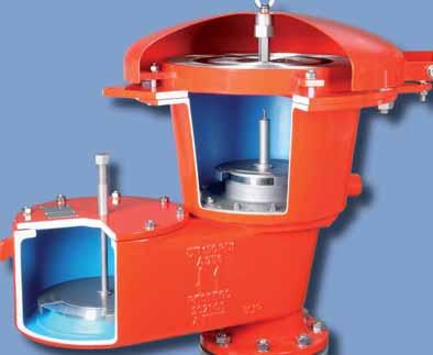
2 Pressure/Vacuum Relief Valves with Flame Arrester end-of-line The working principle and location of the installation of valves on tanks and apparatus is discussed in Technical Fundamentals (Vol. 1). In this chapter we present end-of-line pressure/vacuum relief valves with integrated fl ame arrester units. Function and Description These valves are used to protect process units and equipment (e.g. tanks, pipelines) from exceeding maximum allowable operating pressures and vacuum. In addition theses devices protect against atmospheric defl agration. Some of the devices are also designed to protect against endurance burning (Figure 1). Figure 1: Pressure/Vacuum Relief Valve PROTEGO VD/SV-HRL PROTEGO Pressure Relief Valves with an integrated fl ame arrester unit provide protection against unacceptable overpressure, atmospheric deflagration and endurance burning. In addition the devices reduce emissions almost up to the set pressure. PROTEGO Vacuum Relief Valves with an integrated fl ame arrester unit provide protection against unacceptable vacuum and atmospheric defl agration. In addition they avoid air intake almost up to the set pressure. PROTEGO Pressure Vacuum Relief Valves with an integrated fl ame arrester unit fulfi l all the above mentioned functions for pressure and vacuum relief and protect against atmospheric defl agration or against atmospheric defl agration and endurance burning. The special design of the PROTEGO valves achieves full lift after 10% overpressure above the set pressure. This full-lifttype-technology allows for the use of set pressures just 10% below the maximum allowable working pressure (MAWP or Design Pressure) of the Tank. After just 10% overpressure above set pressure the valve will reach its full capacity to safely relieve the required mass fl ow. Conventional relief valves for low pressure applications need 80%-100% overpressure (API 2000) for reaching full lift and full relieving capacity. They open later and shut off earlier, which results in unnecessary product losses. Special features and advantages Specifi c investments into research and development allowed PROTEGO to design a valve for low pressure applications providing you with the following advantages: 10% full-lift-type-technology reducing product losses (possible reduction of breathing losses greater than 30%) PROTEGO valves open later and shut off earlier than conventional valves, which results in optimized pressure management and reduction of blanketing gas losses increased fl ow performance (result: smaller valves can be installed resulting in capital saving) lowest leak rates world wide for low pressure valves fl ame transmission proof for almost any chemical mixture valve pallet is guided within the housing to protect against harsh weather conditions fl ame arrester unit is not in contact with product vapour under normal operating conditions, which reduces maintenance intervals endurance burning protection against alcohols To achieve the highest expectations of the industry for the lowest leak rates, our valve pallets and seats are manufactured from high quality stainless steel and are hand lapped in a special process. Air cushion membran technology is utilized for low set pressures. Valves with integrated fl ame arrester units are available for substances from explosion groups IIA and IIB3 (NEC D and C) and special approvals are available for alcohols. Main areas of application: as pressure and vacuum valves, as pressure relief valves, as pressure holding/conservation valves, as simple control valves for storage of fl ammable liquids PROTEGO Diaphragm Valves function as pressure vacuum relief valves. The fl exible diaphragm allows them to work as a dynamic fl ame arrester, which provides endurance burning protection. For additional safety these devices are equipped with a static fl ame arrester unit. This one-of-a-kind diaphragm valve can be used under extreme cold weather conditions below freezing and for problem products, which e.g. tend to polymerize (Styrene, Acrylics). A specially designed valve seat combined with the fl exible diaphragm prevents blocking of the valve through freezing product vapours at low temperatures. Ice bridges break and fall off through deformation of the diaphragm if pressure increases. This device has no guiding elements which are likely to stick and keep the device closed. Main areas of application: same as above in storage of fl ammable liquids and specifi cally for storage of monomers. PROTEGO High Velocity Pressure Relief Valves (Jet Valves) open and close almost immediately at set point. This function is achieved by an integrated magnet. Through this the overpressure needed from set point to full lift is practically 0%, which clearly reduces emissions. All PROTEGO high velocity relief valves are tested for oscillating fl ow and are equipped with a specially designed valve cone and seat, which produces a vertical upright free jet during pressure relief. This ensures an effective leaning of the discharged vapours and reduces the gas concentration to a minimum in direct proximity (e.g. boat deck) of the valve. The devices function on the working principal of a dynamic fl ame arrester and are approved for the vapour groups IIA, IIB3 and IIC (NEC D, C and B). Main areas of application: transport of fl ammable liquids on tank ships and special on shore applications. All rights and alterations reserved acc. ISO Active data sheet at 294

3 Installation and servicing All PROTEGO devices are delivered with detailed installation and maintenance manuals. Please pay special attention to the warnings on how to remove transport protection if this has been installed in the device to prevent damage during transport. Specially developed check lists are available to ensure correct installation and operation of the device. Selection and sizing For a safe operation and protection of a plant, the selection and sizing of the correct PROTEGO device is necessary. The following criteria have to be considered for pre-selection: Function: Pressure relief, vacuum relief or combined pressure/ vacuum relief, protection against atmospheric deflagration, or atmospheric defl agration and endurance burning. Type of Valve: Weight loaded valve, diaphragm valve, high velocity pressure relief valve or high velocity pressure relief valve with combined vacuum valve. Design: with horizontal or vertical connection to the protected vessel. These valves are weight loaded, so the pallet has to be installed in an horizontal orientation. The maximum achievable pressure setting will depend on the design of the valve. Metallic sealing or soft sealing are important criteria for low leak rates and have to be chosen based on the intended use. Explosion group: IIA, IIB3, IIC (NEC D, C, B). Process of combustion: endurance burning or atmospheric defl agration Operating conditions: Polymerization, condensation, problems which lead to clogging of the FLAMEFILTER, operating temperature, operating pressure, oxygen concentration, volume fl ow. The valve size has to be determined so that the volume fl ow which has to be discharged does not lead to an increase of internal pressure above the maximum allowable working pressure of the vessel to be protected. For sizing the valves certified pressure/volume fl ow diagrams are provided. The operating conditions have to be known for correct sizing. Sometimes vessels are already equipped with pre-existing nozzles (e.g. old vessels). In such cases the volume fl ow may have to be discharge over several valves. For correct sizing superimposed and builtup backpressure must be considered. Valve sizing: The valve is sized dependent on the required volume fl ow, which is calculated ( Chapter 1), or given. Given: Volume fl ow (e.g. in- or outbreathing of a storage tank as sum of the pump rates and thermal breathing) V. max in m 3 /h (CFH) and maximum allowable (tank-) pressure p in mbar (inch W.C.). Desired: Nominal valve size DN Procedure: The required size of the valve can be taken from the intersection point of V. max and p valve operating pressure = max. allowable tank pressure. The pressure diagram shows the valves fl ow performance in relation to the opening pressure and is determined at the full lift position of the pallet. The set pressure of the valve has to be determined such that the required volume fl ow can be discharged safely. A valve with 10% overpressure characteristic has to be set 10% below the maximum allowable tank pressure. Many conventional valves require 100% overpressure to reach full lift. For these valves the set pressure will be 50% below of the maximum allowable tank pressure. These valves open earlier and shut off later allowing avoidable product losses. Alternatively the valve performance may have to be checked if the required size and maximum allowable tank pressure are provided. Given: (Tank-) nozzle size DN and maximum allowable (tank-) pressure p in mbar (inch W.C.) Desired: fl ow rate of valve in m 3 /h (CFH) and set pressure p set Procedure: The intersection point of the straight line through p and the valve performance curve of the (nozzle-) size DN determine the fl ow rate V. max. The set pressure p set will be 10% (PROTEGO - Technology), 40% or 100% below the maximum allowable (tank-) pressure p T. pressure p (mbar) p T airflow in thousands of CFH fl ow rate V. (m³/h) V. max The set pressure of the valve (= valve starts to open) the maximum allowable pressure of the equipment minus the valves characteristic overpressure which is required for the valve to reach full lift. The overpressure percentage of PROTEGO valves is 10% (unless supplied otherwise). Within 10% overpressure the device will reach its performance at full lift. A further increase in fl ow performance will follow the curve in the pressure volume fl ow diagram. For choosing the correct material the plant and engineering specifi cations have to be considered. pressure - inch W.C. 295
4 Selection Guide PROTEGO Pressure/Vacuum Relief Valves with Flame Arrester end-of-line Pressure setting positive setting range mbar / inch W.C. negative setting range mbar / inch W.C. = endurance burning proof X = prevent flashback in case of atmospheric deflagrations Explosion group Approvals Design = horizontal connection X = vertical connection = soft sealing X = metallic sealing = for critical medium (polymerisation, corrosion, crystallisation) Type Size ATEX NEC Page Pressure Relief Valves, Pallet Type P/EB P/EB-E P/EBR P/EBR-E BE/HR-D " - 3" " - 3" " - 4" " - 4" " - 8" Vacuum Relief Valves, Pallet Type SV/E " - 12" +3.5 up to +210/ +1.4 up to up to +210/ +1.4 up to up to +210/ +1.4 up to up to +210/ +1.4 up to up to +35/ +0.8 up to +14 Pressure/Vacuum Relief Valves, Pallet Type PV/EB PV/EB-E PV/EBR PV/EBR-E VD/SV-AD and VD/SV- ADL " - 3" " - 3" " - 4" " - 4" " - 6" +2.0 up to +210/ +0.8 up to up to +210/ +0.8 up to up to +210/ +0.8 up to up to +210/ +0.8 up to up to +35/ +1.4 up to up to -60/ -0.8 up to up to -35/ -1.4 up to up to -35/ -1.4 up to up to -50/ -1.4 up to up to -50/ -1.4 up to up to -35/ -0.8 up to -14 / X IIA D ATEX X / X / X IIB1 ATEX X / X / X IIA, IIB3 D, C = Heating jacket, heating coil ATEX X / X / X IIB1 ATEX X / X / X IIA D ATEX X / X X IIB3 C ATEX IMO / X / X IIA D ATEX / X / X IIB1 ATEX / X / X IIA, IIB3 D ATEX / X / X IIB1 ATEX / X X IIB3 C ATEX X / X All rights and alterations reserved acc. ISO Active data sheet at 296
5 Pressure setting positive setting range mbar / inch W.C. negative setting range mbar / inch W.C. = endurance burning proof X = prevent flashback in case of atmospheric deflagrations Explosion group Approvals Design = horizontal connection X = vertical connection = soft sealing X = metallic sealing = for critical medium (polymerisation, corrosion, crystallisation) Type Size ATEX NEC Page Pressure/Vacuum Relief Valves, Pallet Type (Continuation) VD/SV-HR " - 4" VD/SV-HRL " - 6" VD/TS " - 12" +3.5 up to +35/ +1.4 up to up to +35/ +1.4 up to up to +50/ +1.4 up to +20 Pressure/Vacuum Relief Valves, Diaphragm Valves UB/SF UB/DF UB/VF " - 6" " - 6" " - 6" +3.5 up to +140/ +1.4 up to up to +140/ +1.4 up to up to -35/ -0.8 up to up to -35/ -0.8 up to up to -25/ -0.8 up to up to -35/ -1.4 up to up to -35/ -1.4 up to -16 / X IIA, IIB3 D, C = Heating jacket, heating coil ATEX X / X / X IIA D ATEX X / X X IIB3 C ATEX FM X / X / X IIB3 C ATEX X / X IIB3 C ATEX X X IIB3 C ATEX X
 in conjunction with a high quality FEP diaphragm.")
6 Pressure Relief Valve deflagration- and endurance burning-proof PROTEGO P/EB Ø a 4 sured by the valve seats made of high quality stainless steel and with individually lapped valve pallets (1) or with an air cushion seal (2) in conjunction with a high quality FEP diaphragm. The valve pallets are also available with a PTFE seal to prevent the valve pallets from sticking when sticky products are used and to enable the use in corrosive fl uids. After the excess pressure is discharged, the valve reseats and provides a tight seal. If the set pressure is exceeded, explosive gas/product-vapour air mixtures are released to the atmosphere. If this mixture ignites, the integrated PROTEGO fl ame arrester unit (3) prevents fl ame transmission into the tank. If additional mixture continues to fl ow and stabilized burning occurs, the integrated fl ame arrester unit prevents fl ashback as a result from endurance burning. The valve is protected and also fulfi ls its function under this severe service conditions. The spring loaded weather hood opens as soon as the fusible element (4) melts. The valve can be used up to an operating temperature of +60 C / 140 F and meets the requirements of European tank design standard EN Appendix L and ISO (API 2000). Type-approved according to ATEX Directive 94/9/EC and EN as well as other international standards. b X 3 Detail X Pressure settings: +3.5 mbar up to +210 mbar +1.4 inch W.C. up to +84 inch W.C. Higher pressure settings upon request. Function and Description DN 1 2 The defl agration-proof and endurance burning-proof P/EB type PROTEGO valve is a highly developed pressure relief valve with an integrated fl ame arrester unit. It is primarily used as a safety device for fl ame transmission proof outbreathing on tanks, containers and process engineering apparatus. The valve offers reliable protection against excess pressure and prevents product losses almost up to the set pressure; it also protects against atmospheric defl agration as well as endurance burning if stabilized burning occurs. The PROTEGO fl ame arrester unit is designed to achieve minimum pressure drop with maximum safety. The P/EB valve is available for substances of explosion group IIA (NEC group D MESG > 0.90 mm). When the set pressure is reached, the valve starts to open and reaches full lift within 10% overpressure. This unique 10% technology enables a set pressure that is only 10% below the maximum allowable working pressure (MAWP) of the tank. After years of development, this typical opening characteristic of a safety relief valve is now also available for the low pressure range. The tank pressure is maintained up to the set pressure with a tightness that is far superior to the conventional standard due to our state of the art manufacturing technology. This feature is en- Special Features and Advantages requires only 10% overpressure to full lift through 10% technology higher set pressures can be used which results in product loss reduction compared to conventional 80% and 100% overpressure technology vents (compare API 2000) more design fl exibility through higher reseating pressures; vents reseat when conventional vent is still discharging costly product or nitrogen high performance seal reducing product loss below EPA s 500ppm rule preventing environmental pollution the valve disc is guided within the housing to protect against harsh weather conditions can be used as protective system according ATEX in areas subject to explosion hazards (94/9/EC) PROTEGO fl ame arrester unit provides protection against atmospheric defl agration and endurance burning fl ame arrester unit integrated into the valve saves space, weight and reduces cost fl ame arrester unit protected from clogging through product vapour fl ame arrester unit has a low pressure drop fl ame transmission proof condensate drain maintenance friendly design modular design enables individual FLAMEFILTER and valve pallet to be replaced All rights and alterations reserved acc. ISO Active data sheet at 298
7 Design Types and Specifications The valve disc is weight-loaded. At set pressure >80 mbar (32.1 inch W.C.), an elongated design is used There are two different designs: Pressure relief valve, basic design P/EB - Pressure relief valve with heating jacket P/EB - H (max. heating fl uid temperature +85 C / 185 F) Additional special devices available upon request Table 1: Dimensions Dimensions in mm / inches To select the nominal size (DN), please use the fl ow capacity chart on the following page DN 50 / 2" 50 / 2" 80 / 3" 80 / 3" Set pressure +80 mbar inch W.C. > +80 mbar > inch W.C. +80 mbar inch W.C. > +80 mbar > inch W.C. a 218 / / / / 8.58 b 287 / / / / Dimensions for Pressure Relief Valve with heating jacket upon request Table 2: Selection of explosion group MESG Expl. Gr. (IEC/CEN) Gas Group (NEC) > 0,90 mm IIA D Table 3: Material selection for housing Design B C Housing Heating jacket (P/EB-H-...) Steel Steel Valve seat Weather hood Steel Special approvals upon request Special materials upon request Table 4: Material combination of flame arrester unit Design A FLAMEFILTER cage FLAMEFILTER Spacer Special materials upon request Table 5: Material selection for valve pallet Design A B C D Pressure range (mbar) +3.5 up to +5.0 >+5.0 up to +14 >+14 up to +210 >+14 up to +210 (inch W.C.) +1.4 up to +2.0 >+2.0 up to +5.6 >+5.6 up to +84 >+5.6 up to +84 Valve pallet Aluminium Sealing FEP FEP Metal to Metal PTFE Special materials and higher pressure settings upon request Table 6: Flange connection type EN , Form B1 or DIN 2501, Form C, PN 16 ANSI 150 lbs RFSF EN or DIN ANSI other types upon request 299
 2307-L The fl ow capacity charts have been determined with a calibrated and TÜV certifi ed fl ow capacity test rig. Volume fl ow V.")
8 Pressure Relief Valve Flow Capacity Chart PROTEGO P/EB P/EB-IIA DN 50 / 2" and 80 / 3" pressure P (mbar) pressure - inch W.C. fl ow rate V. (m³/h) 2307-L The fl ow capacity charts have been determined with a calibrated and TÜV certifi ed fl ow capacity test rig. Volume fl ow V. in (m³/h) and CFH refer to the standard reference conditions of air ISO 6358 (20 C, 1bar). Conversion to other densities and temperatures refer to Vol. 1: Technical Fundamentals. All rights and alterations reserved acc. ISO Active data sheet at 300
9 Notes: 301
 or with an air cushion seal (2) in conjunction with high quality FEP")
10 Pressure Relief Valve deflagration- and endurance burning-proof PROTEGO P/EB-E b Ø a 4 X 3 state of the art manufacturing. This feature is ensured by the valve seats made of high quality stainless steel and with individually lapped valve pallets (1) or with an air cushion seal (2) in conjunction with high quality FEP diaphragm. The valve pallets are also available with a PTFE seal to prevent the valve pallets from sticking when sticky products are used and to enable the use of corrosive fl uids. After the excess pressure is discharged, the valve reseats and provides a tight seal. If the set pressure is exceeded, explosive gas/product-vapour air mixtures are released to the atmosphere. If this mixture ignites, the integrated PROTEGO fl ame arrester unit (3) prevents fl ame transmission into the tank. If additional mixture continues to fl ow and stabilized burning occurs, the integrated fl ame arrester unit prevents fl ashback as a result from endurance burning. The valve is protected and also fulfi ls its function under this severe service conditions. The spring loaded weather hood opens as soon as the fusible element (4) melts. The valve can be used up to an operating temperature of +60 C / 140 F and meets the requirements of European tank design standard EN Appendix L and ISO (API 2000). Type-approved according to ATEX Directive 94/9/EC and EN ISO as well as other international standards. Detail X Pressure settings: +3.5 mbar up to +210 mbar +1.4 inch W.C. up to +84 inch W.C. Higher pressure settings upon request. Function and Description DN 1 2 The defl agration proof and endurance burning-proof P/EB-E type PROTEGO valve is a highly developed pressure relief valve for large fl ows with an integrated fl ame arrester unit that is specially used for applications handling ethanol. It is primarily used as a safety device for fl ame transmission proof outbreathing on tanks, containers and process engineering apparatus. The valve offers reliable protection against excess pressure and prevents product losses almost up to the set pressure; it also protects against atmospheric defl agration as well as endurance burning if stabilized burning occurs. The PROTEGO fl ame arrester unit is designed to achieve minimum pressure drop with maximum safety. The P/EB-E valve is available for substances of explosion group IIB1 (MESG 0.85 mm) and provides specifi c protection against defl agration and endurance burning of alcohol/air mixtures (such as ethanol/air). The valve functions proportional, so the set pressures should be selected in relation to the proportional behaviour (such as a 10%, 40%, or 100% overpressure from the set pressure to the relieving pressure at which the required fl ow performance is reached). The tank pressure is maintained up to set pressure with a tightness that is far superior to the conventional standard due to our Special Features and Advantages selecting set pressure close to relieving pressure results in product loss reduction more design fl exibility through higher reseating pressures; vents reseat when conventional vent is still discharging costly product or nitrogen the valve disc is guided within the housing to protect against harsh weather conditions high performance seal reducing product loss below EPA s 500ppm rule preventing environmental pollution can be used as protective system according to ATEX in areas subject to explosion hazards (94/9/EC) safe against defl agration and endurance burning of alcohol/ air mixtures from explosion group IIB1 high fl ow capacity through large FLAMEFILTER cross-section, results in low pressure drop PROTEGO fl ame arrester unit provides protection against atmospheric defl agration and endurance burning fl ame arrester unit integrated into the valve saves space, weight and reduces cost FLAMEFILTER protected from clogging caused by product vapours fl ame transmission proof condensate drain maintenance friendly design modular design enables individual FLAMEFILTER and valve pallets to be replaced All rights and alterations reserved acc. ISO Active data sheet at 302
11 Design Types and Specifications The valve disc is weight-loaded. At set pressures >80 mbar (32.1 inch W.C.), an elongated design is used There are two different designs: Pressure relief valve, basic design P/EB - E - Pressure relief valve with heating jacket P/EB - E - H (max. heating fl uid temperature +85 C / 185 F) Additional special devices available upon request Table 1: Dimensions Dimensions in mm / inches To select the nominal size (DN), please use the fl ow capacity chart on the following page DN 50 / 2" 50 / 2" 80 / 3" 80 / 3" Set pressure +80 mbar inch W.C. > +80 mbar > inch W.C. +80 mbar inch W.C. > +80 mbar > inch W.C. a 218 / / / / 8.58 b 288 / / / / Dimensions for Pressure Relief Valve with heating jacket upon request Table 2: Selection of explosion group MESG Expl. Gr. (IEC/CEN) Gas Group (NEC) 0,85 mm IIB1 Table 3: Material selection for housing Design B C Housing Heating jacket (P/EB-E-H-...) Steel Steel Valve seat Weather hood Steel Special approvals upon request Special materials upon request Table 4: Material combination of flame arrester unit Design A FLAMEFILTER cage FLAMEFILTER Spacer Special materials upon request Table 5: Material selection for valve pallet Design A B C D Pressure range (mbar) +3.5 up to +5.0 >+5.0 up to +14 >+14 up to +210 >+14 up to +210 (inch W.C.) +1.4 up to +2.0 >+2.0 up to +5.6 >+5.6 up to +84 >+5.6 up to +84 Valve pallet Aluminium Sealing FEP FEP Metal to Metal PTFE Special materials and higher pressure settings upon request Table 6: Flange connection type EN , Form B1 or DIN 2501, Form C, PN 16 ANSI 150 lbs RFSF EN or DIN ANSI other types upon request 303
12 Pressure Relief Valve Flow Capacity Chart PROTEGO P/EB-E overpressure P/EB-E-IIB1 DN 50 / 2" and 80 / 3" pressure P (mbar) pressure - inch W.C. fl ow rate V. (m³/h) 2361-L Remark Set pressure = the valve starts to open set pressure = opening pressure resp. tank design pressure overpressure % % Opening pressure = set pressure plus overpressure Overpressure % = percentage pressure increase over the set pressure The fl ow capacity charts have been determined with a calibrated and TÜV certifi ed fl ow capacity test rig. Volume fl ow V. in (m³/h) and CFH refer to the standard reference conditions of air ISO 6358 (20 C, 1bar). Conversion to other densities and temperatures refer to Vol. 1: Technical Fundamentals. All rights and alterations reserved acc. ISO Active data sheet at 304
13 Notes: 305

14 Pressure Relief Valve deflagration- and endurance burning-proof PROTEGO P/EBR b Detail X Function and Description Ø a DN Pressure settings: +3.5 mbar up to +210 mbar +1.4 inch W.C. up to +84 inch W.C. Higher pressure settings upon request. 1 2 The defl agration-proof and endurance burning-proof P/EBR type PROTEGO valve is a highly developed pressure relief valve for large fl ows with an integrated fl ame arrester unit. It is primarily used as a safety device for fl ame transmission proof outbreathing on tanks, containers and process engineering apparatus. The valve offers reliable protection against excess pressure and prevents product losses almost up to the set pressure; it also protects against atmospheric defl agration as well as endurance burning if stabilized burning occurs. The PROTEGO fl ame arrester unit is designed to achieve minimum pressure drop with maximum safety. P/EBR valves are available for substances from explosion groups IIA and IIB3 (NEC group D and C MESG 0.65 mm). If the set pressure is reached for a valve approved for explosion Group IIA (NEC group D), the valve starts to open and reaches full lift within 10% overpressure. This unique 10% technology enables a set pressure that is only 10% below the maximum allowable working pressure (MAWP) of the tank. After years of development, this typical opening characteristic of a safety relief valve is now also available for the low pressure range. Valves approved for explosion group IIB3 (NEC group C) function proportionally, so the set pressures should be selected in relation to the proportional behaviour (such as a 10%, 40%, or 100% overpressure from the set pressure to the relieving pressure at which the required fl ow performance is reached). X 4 3 The tank pressure is maintained up to the set pressure with a tightness that is far superior to the conventional standard due to our state of the art manufacturing technology. This feature is ensured by the valve seats made of high quality stainless steel and with individually lapped valve pallets (1) or with an air cushion seal (2) in conjunction with high quality FEP diaphragm. The valve pallets are also available with a PTFE seal to prevent the valve pallets from sticking when sticky products are used and to enable the use of corrosive fl uids. After the excess pressure is discharged, the valve reseats and provides a tight seal. If the set pressure is exceeded, explosive gas/product-vapour air mixtures are released to the atmosphere. If this mixture ignites, the integrated PROTEGO fl ame arrester unit (3) prevents fl ame transmission into the tank. If additional mixture continues to fl ow and stabilized burning occurs, the integrated fl ame arrester unit prevents fl ashback as a result from endurance burning. The valve is protected and also fulfi ls its function under this severe service conditions. The spring loaded weather hood opens as soon as the fusible element (4) melts. The valve can be used up to an operating temperature of +60 C / 140 F and meets the requirements of European tank design standard EN Appendix L and ISO (API 2000). Type-approved according to ATEX Directive 94/9/EC as well as other international standards. Special Features and Advantages requires only 10% overpressure to full lift for group IIA ( NEC group D >0.9 MESG) vapours through 10% technology higher set pressures can be used which results in product loss reduction compared to conventional 80% and 100% overpressure technology vents (compare API 2000) more design fl exibility through higher reseating pressures; vents reseat when conventional vent is still discharging costly product or nitrogen the valve disc is guided within the housing to protect against harsh weather conditions high performance seal reducing product loss below EPA s 500ppm rule preventing environmental pollution can be used as protective system according to ATEX in areas subject to explosion hazards (94/9/EC) safe against defl agration and endurance burning for explosion group IIA and IIB3 (NEC group D and C) vapours high fl ow capacity through large FLAMEFILTER crosssection, results in low pressure drop PROTEGO fl ame arrester unit provides protection against atmospheric defl agration and endurance burning fl ame arrester unit integrated into the valve saves space, weight and reduces cost FLAMEFILTER protected from clogging caused by product vapours fl ame transmission proof condensate drain maintenance friendly design modular design enables individual FLAMEFILTER and valve pallets to be replaced All rights and alterations reserved acc. ISO Active data sheet at 306
15 Design Types and Specifications The valve disc is weight-loaded. At set pressures >80 mbar (32.1 inch W.C.), an elongated design is used There are two different designs: Pressure relief valve, basic design P/EBR - Pressure relief valve with heating jacket P/EBR - H (max. heating fl uid temperature +85 C / 185 F) Additional special devices available upon request Table 1: Dimensions Dimensions in mm / inches To select the nominal size (DN), please use the fl ow capacity charts on the following pages DN 80 / 3" 80 / 3" 100 / 4" 100 / 4" Set pressure +80 mbar inch W.C. > +80 mbar > inch W.C. +80 mbar inch W.C. > +80 mbar > inch W.C. a 353 / / / / b 345 / / / / Dimensions for Pressure Relief Valve with heating jacket upon request Table 2: Selection of explosion group MESG Expl. Gr. (IEC/CEN) Gas Group (NEC) > 0,90 mm IIA D > 0,65 mm IIB3 C Special approvals upon request Table 3: Material selection for housing Design B C Housing Heating jacket (P/EBR-H-...) Steel Steel Valve seat Weather hood Steel Special materials upon request Table 4: Material combination of flame arrester unit Design A FLAMEFILTER cage FLAMEFILTER Spacer Special materials upon request Table 5: Material selection for valve pallet Design A B C D Pressure range (mbar) +3.5 up to +5.0 >+5.0 up to +14 >+14 up to +210 >+14 up to +210 (inch W.C.) +1.4 up to +2.0 >+2.0 up to +5.6 >+5.6 up to +84 >+5.6 up to +84 Valve pallet Aluminium Sealing FEP FEP Metal to Metal PTFE Special materials and higher pressure settings upon request Table 6: Flange connection type EN , Form B1 or DIN 2501, Form C, PN 16 ANSI 150 lbs RFSF EN or DIN ANSI other types upon request 307
 2310-L P/EBR-IIB3 DN 80 / 3\" and 100 / 4\" pressure P (mbar) 10 % 40 % 100 % overpressure pressure - inch W.C. fl ow rate V. (m³/h) 2311-L Remark opening pressure resp.")

16 Pressure Relief Valve Flow Capacity Charts PROTEGO P/EBR P/EBR-IIA DN 80 / 3" and 100 / 4" pressure P (mbar) 10 % overpressure pressure - inch W.C. fl ow rate V. (m³/h) 2310-L P/EBR-IIB3 DN 80 / 3" and 100 / 4" pressure P (mbar) 10 % 40 % 100 % overpressure pressure - inch W.C. fl ow rate V. (m³/h) 2311-L Remark opening pressure resp. tank design pressure set pressure = overpressure % 1 + Set pressure = the valve starts to open 100% Opening pressure = set pressure plus overpressure Overpressure % = percentage pressure increase over the set pressure The fl ow capacity charts have been determined with a calibrated and TÜV certifi ed fl ow capacity test rig. Volume fl ow V. in (m³/h) and CFH refer to the standard reference conditions of air ISO 6358 (20 C, 1bar). Conversion to other densities and temperatures refer to Vol. 1: Technical Fundamentals. All rights and alterations reserved acc. ISO Active data sheet at 308
17 Notes: 309
18 Pressure Relief Valve deflagration- and endurance burning-proof PROTEGO P/EBR-E Ø a 4 to our state of the art manufacturing technology. This feature is ensured by the valve seats made of high quality stainless steel and with individually lapped valve pallets (1) or with an air cushion seal (2) in conjunction with high quality FEP diaphragm. The valve pallets are also available with a PTFE seal to prevent the valve pallets from sticking when sticky products are used and to enable the use corrosive fl uids. After the excess pressure is discharged, the valve reseats and provides a tight seal. If the set pressure is exceeded, explosive gas/product-vapour air mixtures are released to the atmosphere. If this mixture ignites, the integrated PROTEGO fl ame arrester unit (3) prevents fl ame transmission into the tank. If additional mixture continues to fl ow and stabilized burning occurs, the integrated fl ame arrester unit prevents fl ashback as a result from endurance burning. The valve is protected and also fulfi ls its function under this severe service conditions. The spring loaded weather hood opens as soon as the fusible element (4) melts. The valve can be used up to an operating temperature of +60 C / 140 F and meets the requirements of European tank design standard EN Appendix L and ISO (API 2000). Type-approved according to ATEX Directive 94/9/EC and EN ISO as well as other international standards. b X 3 Detail X DN Pressure settings: +3.5 mbar up to +210 mbar +1.4 inch W.C. up to +84 inchw.c. Higher pressure settings upon request. Function and Description 1 2 The defl agration proof and endurance burning proof P/EBR-E type PROTEGO valve is a highly developed pressure relief valve for large fl ows with an integrated fl ame arrester unit that is specially used for applications handling ethanol. It is primarily used as a safety device for fl ame transmission proof outbreathing on tanks, containers and process engineering apparatus. The valve offers reliable protection against excess pressure and prevents product losses almost up to the set pressure; it also protects against atmospheric defl agration as well as endurance burning if stabilized burning occurs. The PROTEGO fl ame arrester unit is designed to achieve minimum pressure drop with maximum safety. The P/EBR-E valve is available for substances of explosion group IIB1 (MESG 0.85 mm) and provides specifi c protection against defl agration and endurance burning of alcohol/air mixtures (such as ethanol/air). The valve functions proportional, so the set pressures should be selected in relation to the proportional behaviour (such as a 10%, 40%, or 100% overpressure from the set pressure to the relieving pressure at which the required fl ow performance is reached). The tank pressure is maintained up to the set pressure with a tightness that is far superior to the conventional standard due Special Features and Advantages selecting set pressure close to relieving pressure results in product loss reduction more design fl exibility through higher reseating pressures; vents reseat when conventional vent is still discharging costly product or nitrogen the valve disc is guided within the housing to protect against harsh weather conditions high performance seal reducing product loss below EPA s 500ppm rule preventing environmental pollution can be used as protective system according to ATEX in areas subject to explosion hazards (94/9/EC) safe against defl agration and endurance burning of alcohol/ air mixtures from explosion group IIB1 high fl ow capacity through large fl ame fi lter cross-section, results in low pressure drop PROTEGO fl ame arrester unit provides protection against atmospheric defl agration and endurance burning fl ame arrester unit integrated into the valve saves space, weight and reduces cost FLAMEFILTER protected from clogging caused by product vapours fl ame transmission proof condensate drain maintenance friendly design modular design enables individual FLAMEFILTER and valve pallets to be replaced All rights and alterations reserved acc. ISO Active data sheet at 310
19 Design Types and Specifications The valve disc is weight-loaded. At set pressures >80 mbar (32.1 inch W.C.), an elongated design is used There are two different designs: Pressure relief valve, basic design P/EBR - E - Pressure relief valve with heating jacket P/EBR - E - H (max. heating fl uid temperature +85 C / 185 F) Additional special devices available upon request Table 1: Dimensions Dimensions in mm / inches To select the nominal size (DN), please use the fl ow capacity chart on the following page DN 80 / 3" 80 / 3" 100 / 4" 100 / 4" Set pressure +80 mbar inch W.C. > +80 mbar > inch W.C. +80 mbar inch W.C. > +80 mbar > inch W.C. a 353 / / / / b 345 / / / / Dimensions for Pressure Relief Valve with heating jacket upon request Table 2: Selection of explosion group MESG Expl. Gr. (IEC/CEN) Gas Group (NEC) 0,85 mm IIB1 Special approvals upon request Table 3: Material selection for housing Design B C Housing Heating jacket (P/EBR-E-H-...) Steel Steel Valve seat Weather hood Steel Special materials upon request Table 4: Material combination of flame arrester unit Design A FLAMEFILTER cage FLAMEFILTER Spacer Special materials upon request Table 5: Material selection for valve pallet Design A B C D Pressure range (mbar) +3.5 up to +5.0 >+5.0 up to +14 >+14 up to +210 >+14 up to +210 (inch W.C.) +1.4 up to +2.0 >+2.0 up to +5.6 >+5.6 up to +84 >+5.6 up to +84 Valve pallet Aluminium Sealing FEP FEP Metal to Metal PTFE Special materials and higher pressure settings upon request Table 6: Flange connection type EN , Form B1 or DIN 2501, Form C, PN 16 ANSI 150 lbs RFSF EN or DIN ANSI other types upon request 311
 2364-L Remark Set pressure = the valve starts to open set pressure = opening pressure resp.")
20 Pressure Relief Valve Flow Capacity Chart PROTEGO P/EBR-E P/EBR-E-IIB1 DN 80 / 3" and 100 / 4" pressure P (mbar) 10 % 40 % 100 % overpressure pressure - inch W.C. fl ow rate V. (m³/h) 2364-L Remark Set pressure = the valve starts to open set pressure = opening pressure resp. tank design pressure overpressure % % Opening pressure = set pressure plus overpressure Overpressure % = percentage pressure increase over the set pressure The fl ow capacity charts have been determined with a calibrated and TÜV certifi ed fl ow capacity test rig. Volume fl ow V. in (m³/h) and CFH refer to the standard reference conditions of air ISO 6358 (20 C, 1bar). Conversion to other densities and temperatures refer to Vol. 1: Technical Fundamentals. All rights and alterations reserved acc. ISO Active data sheet at 312
21 Notes: 313


22 Pressure Relief Valve deflagration- and endurance burning-proof PROTEGO BE/HR-D Ø a NG b 4 Detail X 3 1 c 2 X Pressure settings: +2.0 mbar up to +35 mbar +0.8 inch W.C. up to +14 inch W.C. Higher pressure settings upon request. Function and Description The defl agration-proof and endurance burning-proof BE/HR-D type PROTEGO valve is a highly developed pressure relief valve with an integrated fl ame arrester unit. It is primarily used as a safety device for fl ame transmission proof outbreathing on tanks, containers and process engineering apparatus. The valve offers reliable protection against excess pressure and prevents product losses almost up to the set pressure; it also protects against atmospheric deflagration as well as endurance burning if stabilized burning occurs. The PROTEGO fl ame arrester unit is designed to achieve minimum pressure drop with maximum safety. The BE/HR-D valve is available for substances of explosion group IIA (NEC group D MESG > 0.9 mm). When the set pressure is reached, the valve starts to open and reaches full lift within 40% overpressure. The tank pressure is maintained up to the set pressure with a tightness that is far superior to the conventional standard due to our state of the art manufacturing technology. This feature is ensured by the valve seats made of high quality stainless steel and with individually lapped valve pallets (1) or with an air cushion seal (2) in conjunction with high quality FEP diaphragm. After the excess pressure is discharged, the valve reseats and provides a tight seal. If the set pressure is exceeded, explosive gas/product-vapour air mixtures are released to the atmosphere. If this mixture ignites, the integrated PROTEGO fl ame arrester unit (3) prevents fl ame transmission into the tank. If additional mixture continues to fl ow and stabilized burning occurs, the integrated fl ame arrester unit prevents fl ashback as a result from endurance burning. The valve is protected and also fulfi ls its function under this severe service conditions. The spring loaded weather hood opens as soon as the fusible element (4) melts. The valve can be used up to an operating temperature of +60 C / 140 F and meets the requirements of European tank design standard EN Appendix L and ISO (API 2000). DN Type approved according to ATEX Directive 94/9/EC and EN ISO as well as other international standards. Special Features and Advantages requires only 40% overpressure to full lift through 40% technology higher set pressures can be used which results in product loss reduction compared to conventional 80% and 100% overpressure technology vents (compare API 2000) more design fl exibility through higher reseating pressures; vents reseat when conventional vent is still discharging costly product or nitrogen high performance seal reducing product loss below EPA s 500ppm rule preventing environmental pollution the valve disc is guided within the housing to protect against harsh weather conditions can be used as protective system according to ATEX in areas subject to explosion hazards (94/9/EC) high fl ow capacity through large FLAMEFILTER crosssection, results in low pressure drop FLAMEFILTER provides protection against atmospheric defl agration and endurance burning FLAMEFILTER integrated into the valve saves space, weight and reduces cost FLAMEFILTER protected from clogging through product vapours fl ame-transmission-proof condensate drain maintenance-friendly design Design and Specifications The valve disc is weight-loaded. Pressure relief valve, basic design BE/HR-D-400/... Additional special devices available upon request All rights and alterations reserved acc. ISO Active data sheet at 314
23 Table 1: Dimensions To select the nominal size (DN), please use the fl ow capacity chart on the following page DN 150 / 6" 200 / 8" NG 400 / 16" 400 / 16" NG = Nominal size a 600 / / b 545 / / c 485 / / Dimensions in mm / inches Table 2: Selection of explosion group MESG Expl. Gr. (IEC/CEN) Gas Group (NEC) > 0,90 mm IIA D Special approvals upon request Table 3: Material selection for housing Design A B Housing Steel Valve seat Weather hood Steel Flame arrester unit A B Special materials upon request Table 4: Material combinations of flame arrester unit Design A B FLAMEFILTER cage Steel FLAMEFILTER Special materials upon request Table 5: Material selection for valve pallet Design A B C Pressure range (mbar) +2.0 up to +3.5 >+3.5 up to +14 >+14 up to +35 (inch W.C.) +0.8 up to +1.4 >+1.4 up to +5.6 >+5.6 up to +14 Valve pallet Aluminium Sealing FEP FEP Metal to Metal Special materials and higher pressure settings upon request Table 6: Flange connection type EN , Form B1 or DIN 2501, Form C, PN 16 ANSI 150 lbs RFSF EN or DIN ANSI other types upon request 315
24 Pressure Relief Valve Flow Capacity Chart PROTEGO BE/HR-D BE/HR-D-IIA NG 400 / 16" pressure P (mbar) pressure - inch W.C. fl ow rate V. (m³/h) 2123-L Remark Set pressure = the valve starts to open set pressure = opening pressure resp. tank design pressure 1,4 Opening pressure = set pressure plus overpressure Overpressure = pressure increase over the set pressure The fl ow capacity charts have been determined with a calibrated and TÜV certifi ed fl ow capacity test rig. Volume fl ow V. in (m³/h) and CFH refer to the standard reference conditions of air ISO 6358 (20 C, 1bar). Conversion to other densities and temperatures refer to Vol. 1: Technical Fundamentals. All rights and alterations reserved acc. ISO Active data sheet at 316
25 Notes: 317
 prevents fl ame transmission into the tank.")
26 Vacuum Relief Valve deflagration-proof PROTEGO SV/E Ø d X DN b c If the valve is used in atmospheres forming an explosive mixture with air and the mixture ignites, the integrated PROTEGO fl ame arrester unit (3) prevents fl ame transmission into the tank. The standard design is tested at an operating temperature up to +60 C / 140 F (T60) and meets the requirements of European tank design standard EN Appendix L and ISO (API 2000). In addition numerous versions for higher operating temperature are available. Type-approved according to ATEX Directive 94/9/EC and EN ISO as well as other international standards. Additional certifi cates from classifi cation associations for use on ships are also available. Detail X 3 Ø e Vacuum settings: -2.0 mbar up to -60 mbar (-0.2 kpa up to -6 kpa) -0.8 inch W.C. up to -24 inch W.C. Higher vacuum settings upon request Function and Description The defl agration-proof SV/E type PROTEGO valve is a state of the art vacuum relief valve with an integrated fl ame arrester unit. It is primarily used as a safety device for fl ame transmission proof inbreathing on tanks, containers and process engineering apparatus. The valve offers reliable protection against vacuum and prevents inbreathing of air almost up to the set pressure; it also protects against atmospheric deflagration. The PROTEGO fl ame arrester unit is designed to achieve minimum pressure drop with maximum safety. The PROTEGO SV/E valve is available for substances from explosion groups IIA to IIB3 (NEC group D to C MESG 0.65 mm). When the set vacuum is reached, the valve starts to open and reaches full lift within 10% overpressure. This unique 10% technology enables a set vacuum that is only 10% above the maximum allowable working vacuum (MAWV) of the tank. After years of development, this typical opening characteristic of a safety relief valve is now also available for the low pressure range. The tank pressure is maintained up to the set vacuum with a tightness that is far superior to the conventional standard due to our state of the art manufacturing technology. This feature is ensured by the valve seats made of high quality stainless steel and with individually lapped valve pallets (1) or with an air cushion seal (2) in conjunction with high quality FEP diaphragm. The valve pallets are also available with a PTFE seal to prevent the valve pallets from sticking when sticky products are used and to enable the use corrosive fl uids. After the vacuum is equalized, the valve reseats and provides a tight seal. a 1 2 Special Features and Advantages requires only 10% overpressure to full lift extreme tightness and hence least possible product losses and reduced environmental pollution through 10% technology lower set vacuum can be reached which results in product loss reduction compared to conventional 80% and 100% overpressure technology vents (compare API 2000) optimized fl ow performance the valve disc is guided within the housing to protect against harsh weather conditions can be used as protective system according ATEX in areas subject to explosion hazards (94/9/EC) FLAMEFILTER provides protection against atmospheric defl agration FLAMEFILTER integrated into the valve saves space, weight and reduces cost FLAMEFILTER protected from clogging through product vapour PROTEGO fl ame arrester unit has a low pressure drop maintenance friendly design modular design enables individual FLAMEFILTER and valve pallets to be replaced an additional lifting gear can be purchased Design Types and Specifications The valve disc is weight-loaded. Higher vacuum can be achieved upon request with a special spring loaded design. There are four different designs: Vacuum relief valve, basic design SV/E- - Vacuum relief valve with heating jacket SV/E- - H (max. heating fluid temperature +85 C / 185 F) Vacuum relief valve with lifting gear SV/E- S - (ship design) Vacuum relief valve with lifting gear (ship design) and heating jacket SV/E- S - H (max. heating fluid temperature +85 C / 185 F) Additional special devices available upon request All rights and alterations reserved acc. ISO Active data sheet at 318
27 Table 1: Dimensions Dimensions in mm / inches To select the nominal size (DN), please use the fl ow capacity chart on the following page DN 50 / 2" 80 / 3" 100 / 4" 150 / 6" 200 / 8" 250 / 10" 300 / 12" a 140 / / / / / / / b 105 / / / / / / / c 225 / / / / / / / d 170 / / / / / / / e 215 / / / / / / / Table 2: Selection of explosion group MESG Expl. Gr. (IEC/CEN) Gas Group (NEC) 0,65 mm IIB3 C Special approvals upon request Table 3: Specification of max. operating temperature 60 C / 140 F higher operating temperatures upon request T60 Tmaximum allowable operating temperature in C Table 4: Material selection for housing Design B C Housing Heating jacket (SV/E-(S)-H-...) Steel Steel Valve seat Gasket PTFE PTFE Flame arrester unit B B Special materials upon request Table 5: Material combinations of flame arrester unit Design B FLAMEFILTER cage Special materials upon request FLAMEFILTER Table 6: Material selection for valve pallet Design A B C D E F Vacuum range (mbar) -2.0 up to -3.5 <-3.5 up to -14 <-14 up to -35 <-35 up to -60 <-14 up to -35 <-35 up to -60 (inch W.C.) -0.8 up to -1.4 <-1.4 up to -5.6 <-5.6 up to -14 <-14 up to -24 <-5.6 up to -14 <-14 up to -24 Valve pallet Aluminium Sealing FEP FEP Metal to Metal Metal to Metal PTFE PTFE Special materials and higher pressure settings upon request Table 7: Flange connection type EN , Form B1 or DIN 2501, Form C, PN 16; from DN 200 PN 10 ANSI 150 lbs RFSF EN or DIN ANSI other types upon request 319
 1946-L The fl ow capacity charts have been determined with a calibrated and TÜV certifi ed fl ow capacity test rig. Volume fl ow V.")
28 Vacuum Relief Valve Flow Capacity Chart PROTEGO SV/E SV/E-IIB3 vacuum (mbar) vacuum - inch W.C. fl ow rate V. (m³/h) 1946-L The fl ow capacity charts have been determined with a calibrated and TÜV certifi ed fl ow capacity test rig. Volume fl ow V. in (m³/h) and CFH refer to the standard reference conditions of air ISO 6358 (20 C, 1bar). Conversion to other densities and temperatures refer to Vol. 1: Technical Fundamentals. All rights and alterations reserved acc. ISO Active data sheet at 320
29 Notes: 321


30 Pressure/Vacuum Relief Valve deflagration- and endurance burning-proof PROTEGO PV/EB b a DN Detail X Ø d 3 4 Settings: pressure: +2.0 mbar up to +210 mbar +0.8 inch W.C. up to +84 inch W.C. vacuum: -14 mbar up to -35 mbar -5.6 inch W.C. up to -14 inch W.C. vacuum: -3.5 mbar up to -14 mbar -1.4 inch W.C. up to -5.6 inch W.C. for presssure up to max mbar / 60.2 inch W.C. Higher and lower settings upon request Function and Description c X 1 2 The atmospheric defl agration and endurance burning proof PV/EB type PROTEGO valve is a highly developed combined pressure/vacuum relief valve for high fl ow capacities with an integrated fl ame arrester unit. It is primarily used as a safety device for fl ame transmission proof in- and outbreathing on tanks, containers and process engineering apparatus. The valve offers reliable protection against excess pressure and vacuum, prevents the inbreathing of air and product losses almost up to the set pressure and also protects against atmospheric defl a- gration and endurance burning if stabilized burning occurs. The PROTEGO fl ame arrester unit is designed to achieve minimum pressure drop with maximum safety. The PROTEGO PV/EB valve is available for substances of explosion group IIA (NEC group D MESG > 0.9 mm). When the set pressure is reached, the valve starts to open and reaches full lift within 10% over pressure. This unique 10% technology enables a set pressure that is only 10% below the maximum allowable working pressure (MAWP) or maximum allowable working vacuum (MAWV) of the tank. After years of development, this typical opening characteristic of a safety relief valve is now also available for the low pressure range. The tank pressure is maintained up to the set pressure with a tightness that is far superior to the conventional standard due to our state of the art manufacturing technology. This feature is ensured by the valve seats made of high quality stainless steel and with individually lapped valve pallets (1) or with an air cushion seal (2) in conjunction with high quality FEP diaphragm. The valve pallets are also available with a PTFE seal to prevent the valve pallets from sticking when sticky products are used and to enable the use of corrosive fl uids. After the excess pressure is discharged, the valve reseats and provides a tight seal. If the set pressure is exceeded, explosive gas/product-vapour air mixtures are released to the atmosphere. If this mixture ignites, the integrated PROTEGO fl ame arrester unit (3) prevents fl ame transmission into the tank. If additional mixture continues to fl ow and stabilized burning occurs, the integrated fl ame arrester unit prevents fl ashback as a result from endurance burning. The valve is protected and also fulfi ls its function under this severe service conditions. The spring loaded weather hood opens as soon as the fusible element (4) melts. The valve can be used up to an operating temperature of +60 C / 140 F and meets the requirements of European tank design standard EN Appendix L and ISO (API 2000). Type-approved according to ATEX Directive 94/9/EC and EN as well as other international standards. Special Features and Advantages requires only 10% overpressure to full lift through 10% technology higher set pressures can be used which results in product loss reduction compared to conventional 80% and 100% overpressure technology vents (compare API 2000) increased design fl exibility through higher reseating pressures; vents reseat when conventional vent is still discharging costly product or nitrogen high performance seal reducing product loss below EPA s 500ppm rule preventing environmental pollution the valve disc is guided within the housing to protect against harsh weather conditions can be used as protective system according ATEX in areas subject to explosion hazards (94/9/EC) FLAMEFILTER provides protection against atmospheric defl agration and endurance burning FLAMEFILTER integrated into the valve saves space, weight and reduces cost FLAMEFILTER protected from clogging through product vapour PROTEGO fl ame arrester unit has a low pressure drop fl ame transmission proof condensate drain maintenance friendly design special design with lifting gear can be purchased All rights and alterations reserved acc. ISO Active data sheet at 322
31 Design Types and Specifications Almost any combination of vacuum and pressure levels can be set for the valve. The valve discs are weight loaded. When the difference between the pressure and vacuum exceeds 150 mbar / 60.2 inch W.C., special valve discs are used. Table 1: Dimensions To select the nominal size (DN), please use the fl ow capacity charts on the following pages DN 50 / 2" 50 / 2" 80 / 3" 80 / 3" Set pressure +60 mbar inch W.C. > +60 mbar > inch W.C. There are two different designs: Pressure/vacuum relief valve, basic design Pressure/vacuum relief valve with heating jacket (max. heating fl uid temperature +85 C / 185 F) Additional special devices available upon request +60 mbar inch W.C. > +60 mbar > inch W.C. a 308 / / / / b 108 / / / / 4.25 c 165 / / / / 6.57 d 218 / / / / 8.58 PV/EB- PV/EB- H Dimensions in mm / inches Dimensions for pressure/ vacuum relief valve with heating jacket upon request Table 2: Selection of explosion group MESG Expl. Gr. (IEC/CEN) Gas Group (NEC) > 0,90 mm IIA D Table 3: Material selection for housing Design B C Housing Heating jacket (PV/EB-H-...) Steel Steel Valve seats Weather hood Steel Special approvals upon request Special materials upon request Table 4: Material combination of flame arrester unit Design A FLAMEFILTER cage Special materials upon request FLAMEFILTER Spacer Table 5: Material selection for pressure valve pallet Design A B C D Pressure range (mbar) +2.0 up to +3.5 >+3.5 up to +14 >+14 up to +210 >+35 up to +210 (inch W.C.) +0.8 up to +1.4 >+1.4 up to +5.6 >+5.6 up to +84 >+14 up to +84 Valve pallet Aluminium Sealing FEP FEP Metal to Metal PTFE Table 6: Material selection for vacuum pallet Design A B C D Vacuum range (mbar) -3.5 up to -5.0 <-5.0 up to -14 <-14 up to -35 <-14 up to -35 (inch W.C.) -1.4 up to -2.0 <-2.0 up to -5.6 <-5.6 up to -14 <-5.6 up to -14 Valve pallet Aluminium Sealing FEP FEP Metal to Metal PTFE Special material as well as higher set pressure upon request Special material as well as higher set vacuum upon request Table 7: Flange connection type EN , Form B1 or DIN 2501, Form C, PN 16 ANSI 150 lbs RFSF EN or DIN ANSI other types upon request 323
 pressure - inch W.C. fl ow rate V. (m³/h) 2297-L fl ow rate V.")
 and CFH refer to the standard reference conditions of air ISO 6358 (20 C, 1bar). Conversion to other densities and temperatures refer to Vol.")
32 Pressure/Vacuum Relief Valve Flow Capacity Charts PROTEGO PV/EB PV/EB-IIA DN 50/2 and 80/3 pressure PV/EB-IIA DN 50/2 and 80/3 vacuum vacuum (mbar) vacuum - inch W.C. pressure (mbar) pressure - inch W.C. fl ow rate V. (m³/h) 2297-L fl ow rate V. (m³/h) 2298-L The fl ow capacity charts have been determined with a calibrated and TÜV certifi ed fl ow capacity test rig. Volume fl ow V. in (m³/h) and CFH refer to the standard reference conditions of air ISO 6358 (20 C, 1bar). Conversion to other densities and temperatures refer to Vol. 1: Technical Fundamentals. All rights and alterations reserved acc. ISO Active data sheet at 324
33 Notes: 325


34 Pressure/Vacuum Relief Valve deflagration- and endurance burning-proof PROTEGO PV/EB-E b a DN Detail X Ø d 3 4 c 1 2 Settings: pressure: +2.0 mbar up to +210 mbar +0.8 inch W.C. up to +84 inch W.C. vacuum: -14 mbar up to -35 mbar -5.6 inch W.C. up to -14 inch W.C. vacuum: -3.5 mbar up to -14 mbar -1.4 inch W.C. up to -5.6 inch W.C. for presssure up to max mbar / 60.2 inch W.C. Higher and lower settings upon request Function and Description X The defl agration-proof and endurance burning-proof PV/EB-E type PROTEGO valve is a highly developed combined pressure/ vacuum relief valve for high fl ow capacities with an integrated fl ame arrester unit that is specially used for applications handling ethanol. It is primarily used as a safety device for fl ame transmission proof in- and outbreathing on tanks, containers and process engineering apparatus. The valve offers reliable protection against excess pressure and vacuum, prevents the inbreathing of air and product losses almost up to the set pressure and also protects against atmospheric defl agration as well as endurance burning if stabilized burning occurs. The PROTEGO fl ame arrester unit is designed to achieve minimum pressure drop with maximum safety. The PROTEGO PV/EB-E valve is available for substances of explosion group IIB1 (MESG 0.85 mm) and provides specifi c protection against defl agration and endurance burning of alcohol/air mixtures (such as ethanol/air). The valve functions proportionally, so the set pressures should be selected in relation to the proportional behaviour (such as a 10%, 40%, or 100% overpressure from the set pressure to the relieving pressure at which the required fl ow performance is reached). The tank pressure is maintained up to the set pressure with a tightness that is far superior to the conventional standard due to our state of the art manufacturing technology. This feature is ensured by the valve seats made of high quality stainless steel and with individually lapped valve pallets (1) or with an air cushion seal (2) in conjunction with high quality FEP diaphragm. The valve pallets are also available with a PTFE seal to prevent the valve pallets from sticking when sticky products are used and to enable the use of corrosive fl uids. After the excess pressure is discharged, the valve reseats and provides a tight seal. If the set pressure is exceeded, gas/product-vapour air mixtures are released to the atmosphere. If this mixture ignites, the integrated PROTEGO fl ame arrester unit (3) prevents fl ame transmission into the tank. If additional mixture continues to fl ow and stabilized burning occurs, the integrated fl ame arrester unit prevents fl ashback as a result from endurance burning. The valve is protected and also fulfi ls its function under this severe service conditions. The spring loaded weather hood opens as soon as the fusible element (4) melts. The valve can be used up to an operating temperature of +60 C / 140 F and meets the requirements of European tank design standard EN Appendix L and ISO (API 2000). Type-approved according to ATEX Directive 94/9/EC and EN ISO as well as other international standards. Special Features and Advantages selecting set pressure close to relieving pressure results in product loss reduction increased design fl exibility through higher reseating pressures; vents reseat when conventional vent is still discharging costly product or nitrogen the valve disc is guided within the housing to protect against harsh weather conditions high performance seal reducing product loss below EPA s 500ppm rule preventing environmental pollution can be used as protective system according to ATEX in areas subject to explosion hazards (94/9/EC) safe against defl agration and endurance burning of alcohol/ air mixtures from explosion group IIB1 high fl ow capacity through large FLAMEFILTER cross-section, results in low pressure drop FLAMEFILTER provides protection against atmospheric defl agration and endurance burning FLAMEFILTER integrated into the valve saves space, weight and reduces cost FLAMEFILTER protected from clogging caused by product vapours fl ame transmission proof condensate drain maintenance friendly design modular design enables individual FLAMEFILTER and valve pallets to be replaced special design with lifting gear can be purchased All rights and alterations reserved acc. ISO Active data sheet at 326
35 Design Types and Specifications Almost any combination of vacuum and pressure levels can be set for the valve. The valve discs are weight loaded. When the difference between the pressure and vacuum exceeds 150 mbar / 60.2 inch W.C., special valve discs are used. Table 1: Dimensions To select the nominal size (DN), please use the fl ow capacity charts on the following pages DN 50 / 2" 50 / 2" 80 / 3" 80 / 3" Set pressure +60 mbar inch W.C. > +60 mbar inch W.C There are two different designs: Pressure/vacuum relief valve, basic design +60 mbar inch W.C > +60 mbar inch W.C a 308 / / / / b 108 / / / / 4.25 c 165 / / / / 6.57 d 218 / / / / 8.58 PV/EB-E- Pressure/vacuum relief valve with heating jacket PV/EB-E- H (max. heating fl uid temperature +85 C / 185 F) Additional special devices available upon request Dimensions in mm / inches Dimensions for Pressure/ Vacuum Relief Valve with heating jacket upon request Table 2: Selection of explosion group MESG Expl. Gr. (IEC/CEN) Gas Group (NEC) 0,85 mm IIB1 Table 3: Material selection for housing Design B C Housing Heating jacket (PV/EB-E-H-...) Steel Steel Valve seats Weather hood Steel Special approvals upon request Special materials upon request Table 4: Material combination of flame arrester unit Design A FLAMEFILTER cage Special materials upon request FLAMEFILTER Spacer Table 5: Material selection for pressure valve pallet Design A B C D Pressure range (mbar) +2.0 up to +3.5 >+3.5 up to +14 >+14 up to +210 >+35 up to +210 (inch W.C.) +0.8 up to +1.4 >+1.4 up to +5.6 >+5.6 up to +84 >+14 up to +84 Valve pallet Aluminium Sealing FEP FEP Metal to Metal PTFE Table 6: Material selection for vacuum pallet Design A B C D Vacuum range (mbar) -3.5 up to -5.0 <-5.0 up to -14 <-14 up to -35 <-14 up to -35 (inch W.C.) -1.4 up to -2.0 <-2.0 up to -5.6 <-5.6 up to -14 <-5.6 up to -14 Valve pallet Aluminium Sealing FEP FEP Metal to Metal PTFE Special material as well as higher set pressure upon request Special material as well as higher set vacuum upon request Table 7: Flange connection type EN , Form B1 or DIN 2501, Form C, PN 16 ANSI 150 lbs RFSF EN or DIN ANSI other types upon request 327
 2367-L fl ow rate V. (m³/h) 2368-L Remark opening pressure resp.")
36 Pressure/Vacuum Relief Valve Flow Capacity Charts PROTEGO PV/EB-E overpressure pressure (mbar) PV/EB-E-IIB1 DN 50/2 and 80/3 pressure pressure - inch W.C. overpressure PV/EB-E-IIB1 DN 50/2 and 80/3 vacuum vacuum (mbar) vacuum - inch W.C. fl ow rate V. (m³/h) 2367-L fl ow rate V. (m³/h) 2368-L Remark opening pressure resp. tank design pressure set pressure = overpressure % 1 + Set pressure = the valve starts to open 100% Opening pressure = set pressure plus overpressure Overpressure % = percentage pressure increase over the set pressure The fl ow capacity charts have been determined with a calibrated and TÜV certifi ed fl ow capacity test rig. Volume fl ow V. in (m³/h) and CFH refer to the standard reference conditions of air ISO 6358 (20 C, 1bar). Conversion to other densities and temperatures refer to Vol. 1: Technical Fundamentals. All rights and alterations reserved acc. ISO Active data sheet at 328
37 Notes: 329


38 Pressure/Vacuum Relief Valve deflagration- and endurance burning-proof PROTEGO PV/EBR 4 3 Ø d The tank pressure is maintained up to the set pressure with a tightness that is far superior to the conventional standard due to our state of the art manufacturing technology. This feature is ensured by the valve seats made of high quality stainless steel and with individually lapped valve pallets (1) or with an air cushion seal (2) in conjunction with high quality FEP diaphragm. The valve pallets are also available with a PTFE seal to prevent the valve pallets from sticking when sticky products are used and to enable the use of corrosive fl uids. After the excess pressure is discharged, the valve reseats and provides a tight seal. If the set pressure is exceeded, explosive gas/product-vapour air mixtures are released to the atmosphere. If this mixture ignites, the integrated PROTEGO fl ame arrester unit (3) prevents fl ame transmission into the tank. If additional mixture continues to fl ow and stabilized burning occurs, the integrated fl ame arrester unit prevents fl ashback as a result from endurance burning. The valve is protected and also fulfi ls its function under this severe service conditions. The spring loaded weather hood opens as soon as the fusible element (4) melts. The valve can be used up to an operating temperature of +60 C / 140 F and meets the requirements of European tank design standard EN Appendix L and ISO (API 2000). Type-approved according to ATEX Directive 94/9/EC as well as other international standards. b a DN X c Detail X 1 2 Settings: pressure: +2.0 mbar up to +210 mbar +0.8 inch W.C. up to +84 inch W.C. vacuum: -14 mbar up to -50 mbar -5.6 inch W.C. up to -20 inch W.C. vacuum: -3.5 mbar up to -14 mbar -1.4 inch W.C. up to -5.6 inch W.C. for presssure up to max mbar / 60.2 inch W.C. Higher and lower settings upon request Function and Description The defl agration-proof and endurance burning-proof PV/EBR type PROTEGO valve is a highly developed combined pressure/ vacuum relief valve for high fl ow capacities with an integrated fl ame arrester. It is primarily used as a safety device for fl ame transmission proof in- and outbreathing on tanks, containers and process engineering apparatus. The valve offers reliable protection against excess pressure and vacuum, prevents the inbreathing of air and product losses almost up to the set pressure and also protects against atmospheric defl agration as well as endurance burning if stabilized burning occurs. The PROTEGO fl ame arrester unit is designed to achieve minimum pressure drop with maximum safety. PROTEGO PV/EBR valves are available for substances from explosion groups IIA to IIB3 (NEC group D to C MESG 0.65 mm). The valve functions proportional, so the set pressures should be selected in relation to the proportional behaviour (such as a 10%, 40%, or 100% overpressure from the set pressure to the relieving pressure at which the required fl ow performance is reached). Special Features and Advantages selecting set pressure close to relieving pressure results in product loss reduction more design fl exibility through higher reseating pressures; vents reseat when conventional vent is still discharging costly product or nitrogen the valve disc is guided within the housing to protect against harsh weather conditions high performance seal reducing product loss below EPA s 500ppm rule preventing environmental pollution can be used as protective system according to ATEX in areas subject to explosion hazards (94/9/EC) high fl ow capacity through large FLAMEFILTER cross-section, results in low pressure drop FLAMEFILTER provides protection against atmospheric defl agration and endurance burning FLAMEFILTER integrated into the valve saves space, weight and reduces cost FLAMEFILTER protected from clogging caused by product vapours fl ame transmission proof condensate drain maintenance friendly design modular design enables individual FLAMEFILTER and valve pallets to be replaced special design with lifting gear can be purchased All rights and alterations reserved acc. ISO Active data sheet at 330
39 Design Types and Specifications Almost any combination of vacuum and pressure levels can be set for the valve. The valve discs are weight loaded. When the difference between the pressure and vacuum exceeds 150 mbar / 60.2 inch W.C., special valve discs are used. Table 1: Dimensions To select the nominal size (DN), please use the fl ow capacity charts on the following pages DN 80 / 3" 80 / 3" 100 / 4" 100 / 4" Set pressure +35 mbar +14 inch W.C. > +35 mbar > +14 inch W.C. +35 mbar +14 inch W.C. > +35 mbar > +14 inch W.C. a 345 / / / /18.70 b 141 / / / / 5.55 c 218 / / / / 8.58 d 353 / / / / There are two different designs: Pressure/vacuum relief valve, basic design PV/EBR- Pressure /vacuum relief valve with heating jacket PV/EBR- H (max. heating fl uid temperature +85 C / 185 F) Additional special devices available upon request Dimensions in mm / inches Dimensions for pressure/ vacuum relief valve with heating jacket upon request Table 2: Selection of explosion group MESG Expl. Gr. (IEC/CEN) Gas Group (NEC) > 0,90 mm IIA D 0,65 mm IIB3 C Table 3: Material selection for housing Design B C Housing Heating jacket (PV/EBR-H-...) Steel Steel Valve seats Weather hood Steel Special approvals upon request Special materials upon request Table 4: Material combination of flame arrester unit Design A FLAMEFILTER cage Special materials upon request FLAMEFILTER Spacer Table 5: Material selection for pressure valve pallet Design A B C D Pressure range (mbar) +2.0 up to +3.5 >+3.5 up to +14 >+14 up to +210 >+35 up to +210 (inch W.C.) +0.8 up to +1.4 >+1.4 up to +5.6 >+5.6 up to +84 >+14 up to +84 Valve pallet Aluminium Sealing FEP FEP Metal to Metal PTFE Table 6: Material selection for vacuum pallet Design A B C D Vacuum range (mbar) -3.5 up to -5.0 <-5.0 up to -14 <-14 up to -50 <-14 up to -50 (inch W.C.) -1.4 up to -2.0 <-2.0 up to -5.6 <-5.6 up to -20 <-5.6 up to -20 Valve pallet Aluminium Sealing FEP FEP Metal to Metal PTFE Special material as well as higher set pressure upon request Special material as well as higher set vacuum upon request Table 7: Flange connection type EN , Form B1 or DIN 2501, Form C, PN 16 ANSI 150 lbs RFSF EN or DIN ANSI other types upon request 331
 2301-L overpressure fl ow rate V. (m³/h) 2302-L Remark opening pressure resp.")

40 Pressure/Vacuum Relief Valve Flow Capacity Charts PROTEGO PV/EBR overpressure PV/EBR-IIA DN 80/3 and 100/4 pressure PV/EBR-IIA DN 80/3 and 100/4 vacuum vacuum (mbar) vacuum - inch W.C. pressure (mbar) pressure - inch W.C. fl ow rate V. (m³/h) 2301-L overpressure fl ow rate V. (m³/h) 2302-L Remark opening pressure resp. tank design pressure set pressure = overpressure % 1 + Set pressure = the valve starts to open 100% Opening pressure = set pressure plus overpressure Overpressure % = percentage pressure increase over the set pressure The fl ow capacity charts have been determined with a calibrated and TÜV certifi ed fl ow capacity test rig. Volume fl ow V. in (m³/h) and CFH refer to the standard reference conditions of air ISO 6358 (20 C, 1bar). Conversion to other densities and temperatures refer to Vol. 1: Technical Fundamentals. All rights and alterations reserved acc. ISO Active data sheet at 332
")
 2303-L overpressure PV/EBR-IIB3 DN 80/3 and 100/4 vacuum vacuum")
41 Pressure/Vacuum Relief Valve Flow Capacity Charts PROTEGO PV/EBR overpressure PV/EBR-IIB3 DN 80/3 and 100/4 pressure pressure (mbar) pressure - inch W.C. fl ow rate V. (m³/h) 2303-L overpressure PV/EBR-IIB3 DN 80/3 and 100/4 vacuum vacuum (mbar) vacuum - inch W.C. fl ow rate V. (m³/h) 2304-L 333


42 Pressure/Vacuum Relief Valve deflagration- and endurance burning-proof PROTEGO PV/EBR-E b a 4 3 DN Detail X c X Ø d 1 2 Settings: pressure: +2.0 mbar up to +210 mbar +0.8 inch W.C. up to +84 inch W.C. vacuum: -14 mbar up to -50 mbar -5.6 inch W.C. up to -20 inch W.C. vacuum: -3.5 mbar up to -14 mbar -1.4 inch W.C. up to -5.6 inch W.C. for presssure up to max mbar / 60.2 inch W.C. Higher and lower settings upon request Function and Description The defl agration-proof and endurance burning-proof PV/EBR-E type PROTEGO valve is a highly developed combined pressure/vacuum relief valve for high fl ow capacities with an integrated fl ame arrester that is specially used for applications handling ethanol. It is primarily used as a safety device for fl ame transmission proof outbreathing on tanks, containers and process engineering apparatus. The valve offers reliable protection against excess pressure and vacuum, prevents the inbreathing of air and product losses almost up to the set pressure and also protects against atmospheric deflagration as well as endurance burning if stabilized burning occurs. The PROTEGO fl ame arrester unit is designed to achieve minimum pressure drop with maximum safety. The PROTEGO PV/EBR-E valve is available for substances of explosion group IIB1 (MESG 0.85 mm) and provides specifi c protection against defl agration and endurance burning of alcohol/air mixtures (such as ethanol/air). The valve functions proportional, so the set pressures should be selected in relation to the proportional behaviour (such as a 10%, 40%, or 100% overpressure from the set pressure to the relieving pressure at which the required fl ow performance is reached). The tank pressure is maintained up to the set pressure with a tightness that is far superior to the conventional standard due to our state of the art manufacturing technology. This feature is ensured by the valve seats made of high quality stainless steel and with individually lapped valve pallets (1) or with an air cushion seal (2) in conjunction with high quality FEP diaphragm. The valve pallets are also available with a PTFE seal to prevent the valve pallets from sticking when sticky products are used and to enable the use corrosive fl uids. After the excess pressure is discharged, the valve reseats and provides a tight seal. If the set pressure is exceeded, explosive gas/product-vapour air mixtures are released to the atmosphere. If this mixture ignites, the integrated PROTEGO fl ame arrester unit (3) prevents fl ame transmission into the tank. If additional mixture continues to fl ow and stabilized burning occurs, the integrated fl ame arrester unit prevents fl ashback as a result from endurance burning. The valve is protected and also fulfi ls its function under this severe service conditions. The spring loaded weather hood opens as soon as the fusible element (4) melts. The valve can be used up to an operating temperature of +60 C / 140 F and meets the requirements of European tank design standard EN Appendix L and ISO (API 2000). Type-approved according to ATEX Directive 94/9/EC and EN ISO as well as other international standards. Special Features and Advantages selecting set pressure close to relieving pressure results in product loss reduction more design fl exibility through higher reseating pressures; vents reseat when conventional vent is still discharging costly product or nitrogen the valve disc is guided within the housing to protect against harsh weather conditions high performance seal reducing product loss below EPA s 500ppm rule preventing environmental pollution can be used as protective system according to ATEX in areas subject to explosion hazards (94/9/EC) safe against defl agration and endurance burning of alcohol/ air mixtures from explosion group IIB1 high fl ow capacity through large fl ame fi lter cross-section, results in low pressure drop FLAMEFILTER provides protection against atmospheric defl agration and endurance burning FLAMEFILTER integrated into the valve saves space, weight and reduces cost FLAMEFILTER protected from clogging caused by product vapours fl ame transmission proof condensate drain maintenance friendly design modular design enables individual FLAMEFILTER and valve pallets to be replaced special design with lifting gear can be purchased All rights and alterations reserved acc. ISO Active data sheet at 334
43 Design Types and Specifications Almost any combination of vacuum and pressure levels can be set for the valve. The valve discs are weight loaded. When the difference between the pressure and vacuum exceeds 150 mbar / 60.2 inch W.C., special valve discs are used. Table 1: Dimensions To select the nominal size (DN), please use the fl ow capacity charts on the following pages DN 80 / 3" 80 / 3" 100 / 4" 100 / 4" Set pressure +35 mbar +14 inch W.C. > +35 mbar > +14 inch W.C. There are two different designs: Pressure/vacuum relief valve, basic design +35 mbar +14 inch W.C. > +35 mbar > +14 inch W.C. a 345 / / / / b 141 / / / / 5.55 c 218 / / / / 8.58 d 353 / / / / PV/EBR-E- Pressure/vacuum relief valve with heating PV/EBR-E- H jacket (max. heating fl uid temperature +85 C / 185 F) Additional special devices available upon request Dimensions in mm / inches Dimensions for Pressure/ Vacuum Relief Valve with heating jacket upon request Table 2: Selection of explosion group MESG Expl. Gr. (IEC/CEN) Gas Group (NEC) 0,85 mm IIB1 Table 3: Material selection for housing Design B C Housing Heating jacket (PV/EBR-E-H-...) Steel Steel Valve seats Weather hood Steel Special approvals upon request Special materials upon request Table 4: Material combination of flame arrester unit Design A FLAMEFILTER cage Special materials upon request FLAMEFILTER Spacer Table 5: Material selection for pressure valve pallet Design A B C D Pressure range (mbar) +2.0 up to +3.5 >+3.5 up to +14 >+14 up to +210 >+35 up to +210 (inch W.C.) +0.8 up to +1.4 >+1.4 up to +5.6 >+5.6 up to +84 >+14 up to +84 Valve pallet Aluminium Sealing FEP FEP Metal to Metal PTFE Table 6: Material selection for vacuum pallet Design A B C D Vacuum range (mbar) -3.5 up to -5.0 <-5.0 up to -14 <-14 up to -50 <-14 up to -50 (inch W.C.) -1.4 up to -2.0 <-2.0 up to -5.6 <-5.6 up to -20 <-5.6 up to -20 Valve pallet Aluminium Sealing FEP FEP Metal to Metal PTFE Special material as well as higher set pressure upon request Special material as well as higher set vacuum upon request Table 7: Flange connection type EN , Form B1 or DIN 2501, Form C, PN 16 ANSI 150 lbs RFSF EN or DIN ANSI other types upon request 335
44 Pressure/Vacuum Relief Valve Flow Capacity Charts PROTEGO PV/EBR-E overpressure pressure (mbar) PV/EBR-E-IIB1 DN 80/3 and 100/4 pressure pressure - inch W.C. fl ow rate V. (m³/h) 2371-L overpressure PV/EBR-E-IIB1 DN 80/3 and 100/4 vacuum vacuum (mbar) vacuum - inch W.C. fl ow rate V. (m³/h) 2372-L Remark Set pressure = the valve starts to open set pressure = opening pressure resp. tank design pressure overpressure % % Opening pressure = set pressure plus overpressure Overpressure % = percentage pressure increase over the set pressure The fl ow capacity charts have been determined with a calibrated and TÜV certifi ed fl ow capacity test rig. Volume fl ow V. in (m³/h) and CFH refer to the standard reference conditions of air ISO 6358 (20 C, 1bar). Conversion to other densities and temperatures refer to Vol. 1: Technical Fundamentals. All rights and alterations reserved acc. ISO Active data sheet at 336
45 Notes: 337

46 Pressure/Vacuum Relief Valve atmospheric deflagration-proof PROTEGO VD/SV-AD and VD/SV-ADL 3 X b Ø c a velopment, this typical opening characteristic of a safety relief valve is now also available for the low pressure range. The tank pressure is maintained up to the set pressure with a tightness that is far superior to the conventional standard due to our state of the art manufacturing technology. This feature is ensured by the valve seats made of high quality stainless steel and with individually lapped valve pallets (1) or with an air cushion seal (2) in conjunction with high quality FEP diaphragm. The valve pallets are also available with a PTFE seal to prevent the valve pallets from sticking when sticky products are used and to enable the use of corrosive fl uids. After the in- and outbreathing is completed the valve reseats and provides a tight seal. If the set pressure is exceeded, explosive gas/product-vapour air mixtures are released to the atmosphere. If this mixture ignites, the integrated PROTEGO fl ame arrester unit (3) prevents fl ame transmission resulting from atmospheric defl agration into the tank. The vacuum side is also protected against atmospheric defl agration. The valve can be used up to an operating temperature of +60 C / 140 F and meets the requirements of European tank design standard EN Appendix L and ISO (API 2000). Type-approved according to ATEX Directive 94/9/EC and EN ISO as well as other international standards. 3 Detail X Settings: pressure: +3.5 mbar up to +35 mbar +1.4 inch W.C. up to +14 inch W.C. vacuum: -2.0 mbar up to -35 mbar -0.8 inch W.C. up to -14 inch W.C. Higher and lower settings upon request Function and Description The defl agration proof VD/SV-AD(L) type PROTEGO valve is a highly developed combined pressure/vacuum relief valve for high fl ow capacities with an integrated fl ame arrester unit. It is primarily used as a safety device for fl ame-transmission-proof in- and outbreathing in tanks, containers and process engineering apparatus. The valve offers reliable protection against excess pressure and vacuum, preventing outbreathing of product vapour and inbreathing of air almost up to the set pressure and also protects against atmospheric deflagration. The PROTEGO fl ame arrester unit is designed to achieve minimum pressure drop with maximum safety. The defl agration-proof PROTEGO VD/SV-AD(L) valve is available for substances from explosion groups IIA to IIB3 (NEC group D to C MESG 0.65 mm). When the set pressure is reached, the valve starts to open and reaches full lift within 10% overpressure. This unique 10% technology enables a set pressure that is only 10% below the maximum allowable working pressure (MAWP) or maximum allowable working vacuum (MAWV) of the tank. After years of de- DN 1 2 Special Features and Advantages requires only 10% overpressure to full lift through 10% technology set pressures and vacuum closer to MAWP and MAWV can be reached which results in product loss reduction compared to conventional 80% and 100% overpressure technology vents (compare API 2000) more design fl exibility through higher reseating pressures; vents reseat when conventional vent is still discharging costly product or nitrogen high performance seal reducing product loss below EPA s 500ppm rule preventing environmental pollution the valve disc is guided within the housing to protect against harsh weather conditions can be used as protective system according ATEX in areas subject to explosion hazards (94/9/EC) FLAMEFILTER provides protection against atmospheric defl agration FLAMEFILTER integrated into the valve saves space, weight and reduces cost FLAMEFILTER protected from clogging through product vapour FLAMEFILTER has a low pressure drop fl ame transmission proof condensate drain maintenance friendly design modular design enables individual FLAMEFILTER and the valve pallet to be replaced superior technology for API tanks with low MAWP and MAWV All rights and alterations reserved acc. ISO Active data sheet at 338
47 Design Types and Specifications Any combination of vacuum and pressure levels can be set for the valve The valve discs are weight-loaded. There are two different designs: Pressure/vacuum relief valve with housing, standard design VD/SV-AD Pressure/vacuum relief valve with expanded housing VD/SV-ADL Additional special devices available upon request Table 1: Dimensions Dimensions in mm / inches To select the nominal size (DN), please use the fl ow capacity charts on the following pages VD/SV-AD VD/SV-ADL DN 80 / 3" 100 / 4" 100 / 4" 150 / 6" a 540 / / / / b 475 / / / / c 350 / / / / Table 2: Selection of explosion group MESG Expl. Gr. (IEC/CEN) Gas Group (NEC) 0,65 mm IIB3 C Special approvals upon request Table 3: Material selection for housing Design A B Housing Steel Valve seats Gasket PTFE PTFE Weather hood Flame arrester unit A, B B Table 4: Material combinations of flame arrester units Design A B FLAMEFILTER cage Steel FLAMEFILTER Option: Housing with ECTFE-lining Special materials upon request Special materials upon request Table 5: Material selection for pressure valve pallet Design A B C D Pressure range (mbar) +3.5 up to +5.0 >+5.0 up to +14 >+14 up to +35 >+14 up to +35 (inch W.C.) +1.4 up to +2.0 >+2.0 up to +5.6 >+5.6 up to +14 >+5.6 up to +14 Valve pallet Aluminium Sealing FEP FEP Metal to Metal PTFE Table 6: Material selection for vacuum valve pallet Design A B C D Vacuum range (mbar) -2.0 up to -3.5 <-3.5 up to -14 <-14 up to -35 <-14 up to -35 (inch W.C.) -0.8 up to -1.4 <-1.4 up to -5.6 <-5.6 up to -14 <-5.6 up to -14 Valve pallet Aluminium Sealing FEP FEP Metal to Metal PTFE Special material as well as higher set pressure upon request Special material as well as higher set vacuum upon request Table 7: Flange connection type EN , Form B1 or DIN 2501, Form C, PN 16 ANSI 150 lbs RFSF EN or DIN ANSI other types upon request 339
48 Pressure/Vacuum Relief Valve Flow Capacity Charts PROTEGO VD/SV-AD and VD/SV-ADL VD/SV-AD-IIB3 VD/SV-ADL-IIB3 pressure pressure (mbar) pressure - inch W.C. fl ow rate V. (m³/h) 2387-L VD/SV-AD-IIB3 and VD/SV-ADL-IIB3 vacuum vacuum (mbar) vacuum - inch W.C. fl ow rate V. (m³/h) 2234-L The fl ow capacity charts have been determined with a calibrated and TÜV certifi ed fl ow capacity test rig. Volume fl ow V. in (m³/h) and CFH refer to the standard reference conditions of air ISO 6358 (20 C, 1bar). Conversion to other densities and temperatures refer to Vol. 1: Technical Fundamentals. All rights and alterations reserved acc. ISO Active data sheet at 340
49 Notes: 341


50 Pressure/Vacuum Relief Valve deflagration- and endurance burning-proof PROTEGO VD/SV-HR Detail X X b Ø c 1 2 Settings: pressure: +3.5 mbar up to +35 mbar +1.4 inch W.C. up to +14 inch W.C. vacuum: -2.0 mbar up to -35 mbar -0.8 inch W.C. up to -14 inch W.C. Higher and lower settings upon request Function and Description The defl agration-proof and endurance burning-proof VD/SV-HR type PROTEGO valve is a highly developed combined pressure/ vacuum relief valve for high fl ow capacities with an integrated fl ame arrester. It is primarily used as a safety device for fl ametransmission-proof in- and outbreathing in tanks, containers and process engineering apparatus. The valve offers reliable protection against excess pressure and vacuum, preventing outbreathing of product vapour and inbreathing of air almost up to the set pressure and also protects against atmospheric defl agration as well as endurance burning if stabilized burning occurs. The PROTEGO fl ame arrester unit is designed to achieve minimum pressure drop with maximum safety. The defl a- gration and endurance burning proof PROTEGO VD/SV-HR device is available for substances from explosion groups IIA to IIB3 (NEC group D to C MESG 0.65 mm). If the set pressure is reached for a valve approved for explosion Group IIA (NEC group D), the valve starts to open and reaches full lift within 10% overpressure. This unique 10% technology enables a set pressure that is only 10% below the maximum allowable working pressure (MAWP) of the tank. After years of development, this typical opening characteristic of a safety relief valve is now also available for the low pressure range. Valves approved for explosion group IIB3 (NEC group C) function proportionally, so the set pressures should be selected in relation to the proportional behaviour (such as a 10%, 40%, or 100% DN a overpressure from the set pressure to the relieving pressure at which the required flow performance is reached). The tank pressure is maintained up to set pressure with a tightness that is far superior to the conventional standard due to our state of the art manufacturing technology. This feature is ensured by the valve seats made of high quality stainless steel and with individually lapped valve pallets (1) or with an air cushion seal (2) in conjunction with high quality FEP diaphragm. The valve pallets are also available with a PTFE seal to prevent the valve pallets from sticking when sticky products are used and to enable the use of corrosive fl uids. After the excess pressure is discharged, the valve reseats and provides a tight seal. If the set pressure is exceeded, explosive gas/product-vapour air mixtures are released to the atmosphere. If this mixture ignites, the integrated PROTEGO fl ame arrester unit (3) prevents fl ame transmission into the tank. If additional mixture continues to fl ow and stabilized burning occurs, the integrated fl ame arrester unit prevents fl ashback as a result from endurance burning. The valve is protected and also fulfi ls its function under this severe service conditions. The spring loaded weather hood opens as soon as the fusible element (4) melts. The valve can be used up to an operating temperature of +60 C / 140 F and meets the requirements of European tank design standard EN Appendix L and ISO (API 2000). Type-approved according to ATEX Directive 94/9/EC and EN ISO as well as other international standards. Special Features and Advantages requires only 10% overpressure to full lift for explosion group IIA (NEC group D) vapours through 10% technology higher set pressures can be used which results in product loss reduction compared to conventional 80% and 100% overpressure technology vents (compare API 2000) more design fl exibility through higher reseating pressures; vents reseat when conventional vent is still discharging costly product or nitrogen the valve disc is guided within the housing to protect against harsh weather conditions high performance seal reducing product loss below EPA s 500ppm rule preventing environmental pollution can be used as protective system according to ATEX in areas subject to explosion hazards (94/9/EC) safe against defl agration and endurance burning for explosion group IIA and IIB3 (NEC group D and C) vapours high fl ow capacity through large FLAMEFILTER crosssection, results in low pressure drop FLAMEFILTER provides protection against atmospheric defl agration and endurance burning FLAMEFILTER integrated into the valve saves space, weight and reduces cost FLAMEFILTER protected from clogging caused by product vapours fl ame transmission proof condensate drain maintenance friendly design modular design enables individual FLAMEFILTERS and valve pallets to be replaced All rights and alterations reserved acc. ISO Active data sheet at 342
51 Design and Specifications Any combination of vacuum and pressure levels can be set for the valve. The valve discs are weight-loaded. Pressure/vacuum relief valve, basic design VD/SV-HR Additional special devices available upon request Table 1: Dimensions To select the nominal size (DN), please use the fl ow capacity charts on the following pages DN 80 / 3" 100 / 4" a 500 / / b 477 / / c 353 / / Dimensions in mm / inches Table 2: Selection of explosion group MESG Expl. Gr. (IEC/CEN) Gas Group (NEC) > 0,90 mm IIA D 0,65 mm IIB3 C Special approvals upon request Table 3: Material selection for housing Design A B Housing Steel Valve seats Gasket PTFE PTFE Weather hood Steel Flame arrester unit A A Option: Housing with ECTFE-lining Special materials upon request Table 4: Material combination of flame arrester unit Design A FLAMEFILTER cage Special materials upon request FLAMEFILTER Table 5: Material selection for pressure valve pallet Design A B C D Pressure range (mbar) +3.5 up to +5.0 >+5.0 up to +14 >+14 up to +35 >+14 up to +35 (inch W.C.) +1.4 up to +2.0 >+2.0 up to +5.6 >+5.6 up to +14 >+5.6 up to +14 Valve pallet Aluminium Sealing FEP FEP Metal to Metal PTFE Special material as well as higher set pressure upon request Table 6: Material selection for vacuum valve pallet Design A B C D Vacuum range (mbar) -2.0 up to -3.5 <-3.5 up to -14 <+14 up to +35 <-14 up to -35 (inch W.C.) -0.8 up to -1.4 <-1.4 up to -5.6 <-5.6 up to -14 <-5.6 up to -14 Valve pallet Aluminium Sealing FEP FEP Metal to Metal PTFE Special material as well as higher set vacuum upon request Table 7: Flange connection type EN , Form B1 or DIN 2501, Form C, PN 16 ANSI 150 lbs RFSF EN or DIN ANSI other types upon request 343
52 Pressure/Vacuum Relief Valve Flow Capacity Charts PROTEGO VD/SV-HR VD/SV-HR-IIA pressure VD/SV-HR-IIA vacuum vacuum (mbar) vacuum - inch W.C. pressure (mbar) pressure - inch W.C. fl ow rate V. (m³/h) 2202-L fl ow rate V. (m³/h) 2203-L The fl ow capacity charts have been determined with a calibrated and TÜV certifi ed fl ow capacity test rig. Volume fl ow V. in (m³/h) and CFH refer to the standard reference conditions of air ISO 6358 (20 C, 1bar). Conversion to other densities and temperatures refer to Vol. 1: Technical Fundamentals. All rights and alterations reserved acc. ISO Active data sheet at 344
53 Pressure/Vacuum Relief Valve Flow Capacity Charts PROTEGO VD/SV-HR overpressure pressure (mbar) VD/SV-HR-IIB3 DN 80/3" and 100/4" pressure pressure - inch W.C. fl ow rate V. (m³/h) 2384-L Remark Set pressure = the valve starts to open set pressure = VD/SV-HR-IIB3 vacuum vacuum (mbar) vacuum - inch W.C. opening pressure resp. tank design pressure overpressure % % Opening pressure = set pressure plus overpressure Overpressure % = percentage pressure increase over the set pressure fl ow rate V. (m³/h) 2412-L 345

54 Pressure/Vacuum Relief Valve deflagration- and endurance burning-proof PROTEGO VD/SV-HRL a 4 3 Detail X Settings: pressure: +3.5 mbar up to +35 mbar +1.4 inch W.C. up to +14 inch W.C. vacuum: -2.0 mbar up to -35 mbar -0.8 inch W.C. up to -14 inch W.C. Higher and lower settings upon request X Function and Description b Ø c The atmospheric defl agration and endurance burning proof VD/SV-HRL type PROTEGO valve is a highly developed combined pressure/vacuum relief valve for high fl ow capacities with an integrated fl ame arrester. It is primarily used as a safety device for fl ame transmission proof in- and outbreathing on tanks, containers and process engineering apparatus. The valve offers reliable protection against excess pressure and vacuum, prevents the inbreathing of air and product losses almost up to the set pressure and also protects against atmospheric deflagration and endurance burning if stabilized burning occurs. The PROTEGO fl ame arrester unit is designed to achieve minimum pressure drop with maximum safety. The PROTEGO VD/SV-HRL device is available for substances of explosion group IIA (NEC group D MESG > 0.9 mm). When the set pressure is reached, the valve starts to open and reaches full lift within 10% overpressure. This unique 10% technology enables a set pressure that is only 10% below the maximum allowable working pressure (MAWP) or maximum DN 1 2 allowable working vacuum (MAWV) of the tank. After years of development, this typical opening characteristic of a safety relief valve is now also available for the low pressure range. The tank pressure is maintained up to the set pressure with a tightness that is far superior to the conventional standard due to our state of the art manufacturing technology. This feature is ensured by the valve seats made of high quality stainless steel and with individually lapped valve pallets (1) or with an air cushion seal (2) in conjunction with high quality FEP diaphragm. The valve pallets are also available with a PTFE seal to prevent the valve pallets from sticking when sticky products are used and to enable the use of corrosive fl uids. After the ex- cess pressure is discharged, the valve reseats and provides a tight seal. If the set pressure is exceeded, explosive gas/product-vapour air mixtures are released to the atmosphere. If this mixture ig- nites, the integrated PROTEGO fl ame arrester unit (3) prevents fl ame transmission into the tank. If additional mixture continues to fl ow and stabilized burning occurs, the integrated fl ame ar- rester unit prevents fl ashback as a result from endurance burning. The valve is protected and also fulfi ls its function under this severe service conditions. The spring loaded weather hood opens as soon as the fusible element (4) melts. The valve can be used up to an operating temperature of +60 C / 140 F and meets the requirements of European tank design standard EN Appendix L and ISO (API 2000). Type-approved according to ATEX Directive 94/9/EC and EN ISO as well as other international standards. Special Features and Advantages requires only 10% overpressure to full lift through 10% technology higher set pressures can be used which results in product loss reduction compared to conventional 80% and 100% overpressure technology vents (compare API 2000) increased design fl exibility through higher reseating pressures; vents reseat when conventional vent is still discharging costly product or nitrogen high performance seal reducing product loss below EPA s 500ppm rule preventing environmental pollution the valve disc is guided within the housing to protect against harsh weather conditions can be used as protective system according ATEX in areas subject to explosion hazards (94/9/EC) FLAMEFILTER provides protection against atmospheric defl agration and endurance burning FLAMEFILTER integrated into the valve saves space, weight and reduces cost All rights and alterations reserved acc. ISO Active data sheet at 346
55 FLAMEFILTER protected from clogging through product vapour FLAMEFILTER has low pressure drop flame transmission proof condensate drain maintenance friendly design superior technology for API tanks Design and Specifications Table 1: Dimensions To select the nominal size (DN), please use the fl ow capacity charts on the following pages DN 100 / 4" 150 / 6" a 650 / / b 1000 / / c 600 / / Any combination of vacuum and pressure levels can be set for the valve. The valve discs are weight-loaded. Pressure/vacuum relief valve, basic design VD/SV-HRL Additional special devices available upon request Dimensions in mm / inches Table 2: Selection of explosion group MESG Expl. Gr. (IEC/CEN) Gas Group (NEC) > 0,90 mm IIA D Special approvals upon request Table 3: Material selection for housing Design A B Housing Steel Valve seats Gasket PTFE PTFE Weather hood Steel Flame arrester unit A, B B Option: Housing with ECTFE-lining Special materials upon request Table 4: Material combinations of flame arrester unit Design A B FLAMEFILTER cage Steel FLAMEFILTER Special materials upon request Table 5: Material selection for pressure valve pallet Design A B C D Pressure range (mbar) +3.5 up to +5.0 >+5.0 up to +14 >+14 up to +35 >+14 up to +35 (inch W.C.) +1.4 up to +2.0 >+2.0 up to +5.6 >+5.6 up to +14 >+5.6 up to +14 Valve pallet Aluminium Sealing FEP FEP Metal to Metal PTFE Special material as well as higher set pressure upon request Table 6: Material selection for vacuum valve pallet Design A B C D Vacuum range (mbar) -2.0 up to -3.5 <-3.5 up to -14 <+14 up to +35 <-14 up to -35 (inch W.C.) -0.8 up to -1.4 <-1.4 up to -5.6 <-5.6 up to -14 <-5.6 up to -14 Valve pallet Aluminium Sealing FEP FEP Metal to Metal PTFE Special material as well as higher set vacuum upon request Table 7: Flange connection type EN , Form B1 or DIN 2501, Form C, PN 16 ANSI 150 lbs RFSF EN or DIN ANSI other types upon request 347
56 Pressure/Vacuum Relief Valve Flow Capacity Charts PROTEGO VD/SV-HRL VD/SV-HRL-IIA pressure pressure (mbar) pressure - inch W.C. fl ow rate V. (m³/h) 2207-L VD/SV-HRL-IIA vacuum vacuum (mbar) vacuum - inch W.C. fl ow rate V. (m³/h) 2208-L The fl ow capacity charts have been determined with a calibrated and TÜV certifi ed fl ow capacity test rig. Volume fl ow V. in (m³/h) and CFH refer to the standard reference conditions of air ISO 6358 (20 C, 1bar). Conversion to other densities and temperatures refer to Vol. 1: Technical Fundamentals. All rights and alterations reserved acc. ISO Active data sheet at 348
57 Notes: 349

58 Pressure/Vacuum Relief Valve atmospheric deflagration-proof PROTEGO VD/TS a d FM Approvals Specifi cation Tested Detail X 3 c X 1 2 Function and Description Ø b The atmospheric defl agration-proof VD/TS type PROTEGO valve is a highly developed combined pressure/vacuum relief valve for high fl ow capacities with an integrated fl ame arrester unit. It is primarily used as a safety device for fl ame transmission proof in- and outbreathing on tanks, containers and process engineering apparatus. The valve offers reliable protection against excess pressure and vacuum, prevents the inbreathing of air and product losses almost up to the set pressure and also protects against atmospheric defl agration. The PROTEGO fl ame arrester unit is designed to achieve minimum pressure drop with maximum safety. The PROTEGO VD/TS device is available for substances from explosion groups IIA to IIB3 (NEC group D to C MESG 0.65 mm). When the set pressure is reached, the valve starts to open and reaches full lift within 10% overpressure. This unique 10% technology enables a set pressure that is only 10% below the maximum allowable working pressure (MAWP) or maximum allowable working vacuum (MAWV) of the tank. After years of development, this typical opening characteristic of a safety relief valve is now also available for the low pressure range. DN Settings: pressure: +3.5 mbar up to +50 mbar +1.4 inch W.C. up to +20 inch W.C. vacuum: -2.0 mbar up to -25 mbar -0.8 inch W.C. up to -10 inch W.C. Higher and lower settings upon request The tank pressure is maintained up to the set pressure with a tightness that is far superior to the conventional standard due to our state of the art manufacturing technology. This feature is ensured by the valve seats made of high quality stainless steel and with individually lapped valve pallets (1) or with an air cushion seal (2) in conjunction with high quality FEP diaphragm. The valve pallets are also available with a PTFE seal to prevent the valve pallets from sticking when sticky products are used and to enable the use of corrosive fl uids. After the excess pressure is discharged, the valve reseats and provides a tight seal. If the set pressure is exceeded, explosive gas/product-vapour air mixtures are released to the atmosphere. If this mixture ignites, the integrated PROTEGO fl ame arrester unit (3) prevents fl ame transmission into the tank. The standard design is tested at an operating temperature up to +60 C / 140 F and meets the requirements of European tank design standard EN Appendix L and ISO (API 2000). In addition numerous versions for higher operating temperature are available. Type-approved according to ATEX Directive 94/9/EC and EN ISO as well as other international standards. Special Features and Advantages requires only 10% overpressure to full lift extreme tightness and hence least possible product losses and reduced environmental pollution through 10% technology higher set pressures can be used which results in product loss reduction compared to conventional 80% and 100% overpressure technology vents (compare API 2000) the valve disc is guided within the housing to protect against harsh weather conditions can be used as protective system according ATEX in areas subject to explosion hazards (94/9/EC) FLAMEFILTER provides protection against atmospheric defl agration FLAMEFILTER integrated into the valve saves space and reduces cost FLAMEFILTER protected from clogging through product vapour PROTEGO fl ame arrester unit has low pressure drop optimized fl ow performance maintenance friendly design sturdy housing design superior technology for API tanks Design and Specifications Any combination of vacuum and pressure levels can be set for the valve. The valve discs are weight loaded. Pressure/vacuum relief valve, basic design VD/TS- Additional special devices available upon request All rights and alterations reserved acc. ISO Active data sheet at 350
59 Table 1: Dimensions Dimensions in mm / inches To select the nominal size (DN), please use the fl ow capacity charts on the following pages DN 50 / 2" 80 / 3" 100 / 4" 125 / 5" 150 / 6" 200 / 8" 250 / 10" 300 / 12" a 340 / / / / / / / / b 210 / / / / / / / / c 206 / / / / / / / / d 125 / / / / / / / / Table 2: Selection of explosion group MESG Expl. Gr. (IEC/CEN) Gas Group (NEC) 0,65 mm IIB3 C Special approvals upon request Table 3: Specification of max. operating temperature 60 C / 140 F higher operating temperatures upon request T60 Tmaximum allowable operating temperature in C Table 4: Material selection for housing Design A C D E Housing Aluminium Steel Hastelloy Valve seats Hastelloy Gasket PTFE PTFE PTFE PTFE Weather hood Aluminium Aluminium Hastelloy Flame arrester unit A A A C Pressure valve pallet A-F A-F A-F G-I Vacuum valve pallet A-E A-E A-E F-H Special materials upon request Table 5: Material combination of flame arrester unit Design A C FLAMEFILTER cage Hastelloy FLAMEFILTER Hastelloy Special materials upon request Table 6: Material selection for pressure pallet Design A B C D E Pressure range (mbar) +3.5 up to +5,0 >+5.0 up to +14 >+14 up to +35 >+35 up to +50 >+14 up to +35 (inch W.C.) +1.4 up to +2.0 >+2.0 up to +5.6 >+5.6 up to +14 >+14 up to +20 >+5.6 up to +14 Valve pallet Aluminium Sealing FEP FEP Metal to Metal Metal to Metal PTFE Weight Lead Design F G H I Pressure range (mbar) >+35 up to up to +5,0 >+5.0 up to +14 >+14 up to +35 (inch W.C.) >+14 up to up to +2.0 >+2.0 up to +5.6 >+5.6 up to +14 Valve pallet Titanium Hastelloy Hastelloy Sealing PTFE FEP FEP Metal to Metal Weight Lead Hastelloy Hastelloy Hastelloy Special material as well as higher set pressure upon request 351
60 Pressure/Vacuum Relief Valve atmospheric deflagration-proof PROTEGO VD/TS FM Approvals Specification Tested Table 7: Material selection for vacuum pallet Design A B C E F Vacuum range (mbar) -2.0 up to -3.5 <-3.5 up to -14 <-14 up to -25 <-14 up to up to -3.5 (inch W.C.) -0.8 up to -1.4 <-1.4 up to -5.6 <-5.6 up to -10 <-5.6 up to up to -1.4 Valve pallet Aluminium Titanium Sealing FEP FEP Metal to Metal PTFE FEP Weight Hastelloy Design G H Vacuum range (mbar) <-3.5 up to -14 <-14 up to -25 (inch W.C.) <-1.4 up to -5.6 <-5.6 up to -10 Valve pallet Hastelloy Hastelloy Sealing FEP Metal to Metal Weight Hastelloy Hastelloy Special material as well as higher set vacuum upon request Table 8: Flange connection type EN , Form B1 or DIN 2501, Form C, PN 16; from DN 200 PN 10 ANSI 150 lbs RFSF EN or DIN ANSI other types upon request All rights and alterations reserved acc. ISO Active data sheet at 352
61 Pressure/Vacuum Relief Valve Flow Capacity Charts PROTEGO VD/TS VD/TS-IIB3 pressure pressure (mbar) pressure - inch W.C. fl ow rate V. (m³/h) 2605-L * at set pressure of +22 to +50 mbar / +8.8 to +20 inch W.C. a volume fl ow reduction of 15% has to be made on the vacuum side VD/TS-IIB3 vacuum vacuum (mbar) vacuum - inch W.C. fl ow rate V. (m³/h) 2606-L The fl ow capacity chart has been determined with a calibrated and TÜV certifi ed fl ow capacity test rig. Volume fl ow V. in (m³/h) and CFH refer to the standard reference conditions of air ISO 6358 (20 C, 1bar). Conversion to other densities and temperatures refer to Vol. 1: Technical Fundamentals. 353
. a 8 5 3 Settings: pressure: DN 80 +3.")

62 Pressure/Vacuum Diaphragm Valve deflagration- and endurance burning-proof PROTEGO UB/SF 7 Ø b 4 The set pressure is adjusted with a freeze resistant water-glycol mixture, which assures safe operation under extreme cold weather conditions. The PROTEGO UB/SF valve is available for substances of explosion group IIB3 (NEC group C MESG 0.65 mm). a Settings: pressure: DN mbar up to +50 mbar +1.4 inch W.C. up to +20 inch W.C. DN mbar up to +45 mbar +1.4 inch W.C. up to +18 inch W.C. DN mbar up to +46 mbar +1.4 inch W.C. up to inch W.C. Higher pressure settings up to +140 mbar (56.2 inch W.C.) in special design with additional liquid reservoir as well as lower pressure settings upon request. vacuum: 3.5 mbar up to 35 mbar 1.4 inch W.C. up to 14 inch W.C. Higher and lower vacuum settings upon request Function and Description The defl agration- and endurance burning-proof UB/SF type PROTEGO diaphragm valve is a state of the art pressure- and vacuum- relief valve combining the function of a dynamic and static fl ame arrester. Worldwide this design is unique. It is primarily used as a safety device for fl ame transmission proof in- and outbreathing on tanks, containers and process engineering apparatus. The valve offers reliable protection against excess pressure and vacuum, prevents the inbreathing of air and product losses almost up to the set pressure and protects against atmospheric deflagration and endurance burning if stabilized burning occurs. The PROTEGO UB/SF diaphragm valve has proven its performance over many years in a great variety of severe applications in the petrochemical and chemical industry. Worldwide it is the only vent which functions in services such as styrene and acrylics. DN When the pressure in the tank reaches the set pressure, the diaphragm (1) on the outer valve seat ring (2) is lifted and vapours vent to the environment. The set pressure is adjusted by the liquid (water-glycol mixture) column height, which is fi lled into the outer ring chamber (3). The overpressure chamber is equipped with an opening (4) to keep the pressure in balance with the ambient pressure. The opening is equipped with a FLAMEFILTER to avoid fl ame transmission into the overpressure chamber. If a vacuum builds up in the tank, it is transmitted through pressure balancing tubes into the vacuum chamber (5) (inner chamber). If the set vacuum, which depends on the liquid column height in the vacuum chamber, is reached the atmospheric pressure lifts the diaphragm off the inner valve seat ring (6). Ambient air can now fl ow into the tank. The liquid column heights, which affect the set pressures and vacuum, can be checked by fl oating level indicators (7). The tank pressure is maintained up to the set pressure with a tightness that is far superior to the conventional standard due to our highly developed manufacturing technology. This is achieved because the liquid loaded diaphragm presses tightly around the special designed valve seat surface area, even when the operating pressure increases. This is extremely important to reduce leakage to an absolute minimum. After the excess pressure or vacuum is discharged, the valve reseats and provides a tight seal. If the tank pressure exceeds the adjusted set pressure, explosive gas/product-vapour air mixtures exit. The speed at which these mixtures exit the annular gap between the diaphragm and the outer valve seat ring while overcoming the set pressure is much faster than the fl ame speed. If this mixture ignites, fl ashback into the tank is prevented. If the mixture fl ow continues, the dynamic fl ame arresting feature prevents fl ashback ignition even in the case of endurance burning. Even at relatively low fl ow rates, which occur during thermal outbreathing, the gap formed by the volumetric fl ow is so narrow that fl ames are extinguished in the gap and fl ashback is prevented. At very low pressure settings the explosion pressures resulting from an atmospheric defl agration may be strong enough to lift the diaphragm off the valve seat rings so that fl ashback could result. The ignition into the tank can be prevented by installing the PROTEGO fl ame arrester unit (8). This fl ame arrester unit provides additional protection against atmospheric defl agration during regular maintenance and inspection. All rights and alterations reserved acc. ISO Active data sheet at 354
63 The valve can be used up to an operating temperature of +60 C / 140 F and meets the requirements of European tank design standard EN Appendix L and ISO (API 2000). Type-approved according to ATEX Directive 94/9/EC and EN ISO as well as other international standards. Special Features and Advantages high performance seal reducing product loss below EPA s 500ppm rule preventing environmental pollution set pressure close to opening pressure enables optimum pressure maintenance in the system high fl ow capacity can be used as a protective system according to ATEX 94/9/EC in areas subject to an explosion hazard protection against atmospheric defl agrations and endurance burning for products up to explosion group IIB3 (NEC group C MESG 0.65 mm) minimum pressure drop of the FLAMEFILTER fl ame-transmission-proof pressure and vacuum chambers freeze protection at sub-zero conditions self draining function for condensate liquid column height is monitored by level indicators easy maintenance through hinged vent cap modular design enables individual FLAMEFILTER discs and valve diaphragm to be replaced particularly suitable for problematic products such as styrene, acrylics, etc. Design Types and Specifications Almost any combination of vacuum and pressure settings can be utilized for the valve. The diaphragm is pressurized by liquid. Higher pressures can be achieved upon request with a special liquid reservoir. When there is a substantial difference between the pressure and vacuum, special designs with weight-loaded vacuum discs are used. There are two different designs: Pressure/vacuum diaphragm valve, basic UB/SF - design Pressure/vacuum diaphragm valve with heating UB/SF - H coil (max. heating fl uid temperature +85 C / 185 F) In addition to the standard design, a series of specially developed designs, which are particularly suitable for operating conditions to which these products are subjected, can be provided upon request (for example, for acrylics or styrene storage tanks, etc.). Remark set pressure = Set pressure = the valve starts to open Opening pressure = set pressure plus overpressure Overpressure opening pressure resp. tank design pressure 1,4 = pressure increase over the set pressure Table 1: Dimensions Dimensions in mm / inches To select the nominal size (DN), please use the fl ow capacity charts on the following pages DN pressure 80 / 3" 100 / 4" 150 / 6" a up to +28 mbar / inch W.C. 615 / / / a > +28 mbar / inch W.C. 765 / / / b 410 / / / Pressure settings > +50 mbar / +20 inch W.C. (DN 80/3 ), > +45 mbar / +18 inch W.C. (DN 100/4 ), > +46 mbar / inch W.C. (DN150/6 ) with additional liquid reservoir - dimensions upon request Dimensions for pressure/vacuum diaphragm valves with heating coil upon request Table 2: Selection of explosion group MESG Expl. Gr. (IEC/CEN) Gas Group (NEC) 0,65 mm IIB3 C Special approvals upon request 355
64 Pressure/Vacuum Diaphragm Valve deflagration- and endurance burning-proof PROTEGO UB/SF Table 3: Material selection for housing Design C D Housing Steel Valve top Heating coil (UB/SF-H-...) Valve seats Gasket FPM PTFE Diaphragm A, B A, B Flame arrester unit C C Option: Housing with ECTFE-lining Special materials upon request Table 4: Material selection for diaphragm Design A B Diaphragm FPM FEP Special materials upon request Table 5: Material combinations of flame arrester unit Design C FLAMEFILTER cage Special materials upon request FLAMEFILTER Spacer Table 6: Flange connection type EN , Form B1 or DIN 2501, Form C, PN 16 ANSI 150 lbs RFSF EN or DIN ANSI other types upon request All rights and alterations reserved acc. ISO Active data sheet at 356
65 Pressure/Vacuum Diaphragm Valve Flow Capacity Charts - Pressure PROTEGO UB/SF-80 adjusted set pressure mbar / inch W.C.: UB/SF-80-IIB3 - pressure set pressure from +3.5 up to 25 mbar / +1.4 up to 10 inch W.C. interpolate intermediate sizes tank pressure (mbar) tank pressure - inch W.C. fl ow rate V. (m³/h) 2085-L adjusted set pressure mbar / inch W.C.: UB/SF-80-IIB3 - pressure set pressure from >+25 up to 140 mbar / >+10 up to 56 inch W.C. interpolate intermediate sizes tank pressure (mbar) tank pressure - inch W.C. fl ow rate V. (m³/h) 2085-L The fl ow capacity chart has been determined with a calibrated and TÜV certifi ed fl ow capacity test rig. Volume fl ow V. in (m³/h) and CFH refer to the standard reference conditions of air ISO 6358 (20 C, 1bar). Conversion to other densities and temperatures refer to Vol. 1: Technical Fundamentals. 357
66 Pressure/Vacuum Diaphragm Valve Flow Capacity Charts - Pressure PROTEGO UB/SF-100 adjusted set pressure mbar / inch W.C.: UB/SF-100-IIB3 - pressure set pressure from +3.5 up to 25 mbar / +1.4 up to 10 inch W.C. interpolate intermediate sizes adjusted set pressure mbar / inch W.C.: UB/SF-100-IIB3 - pressure set pressure from >+25 up to 140 mbar / >+10 up to 56 inch W.C. interpolate intermediate sizes tank pressure (mbar) tank pressure - inch W.C. tank pressure (mbar) tank pressure - inch W.C. fl ow rate V. (m³/h) 2086-L fl ow rate V. (m³/h) 2086-L The fl ow capacity charts have been determined with a calibrated and TÜV certifi ed fl ow capacity test rig. Volume fl ow V. in (m³/h) and CFH refer to the standard reference conditions of air ISO 6358 (20 C, 1bar). Conversion to other densities and temperatures refer to Vol. 1: Technical Fundamentals. All rights and alterations reserved acc. ISO Active data sheet at 358
67 Pressure/Vacuum Diaphragm Valve Flow Capacity Charts - Pressure PROTEGO UB/SF-150 adjusted set pressure mbar / inch W.C.: UB/SF-150-IIB3 - pressure set pressure from +3.5 up to 25 mbar / +1.4 up to 10 inch W.C. interpolate intermediate sizes adjusted set pressure mbar / inch W.C.: UB/SF-150-IIB3 - pressure set pressure from >+25 up to 140 mbar / >+10 up to 56 inch W.C. interpolate intermediate sizes tank pressure (mbar) tank pressure - inch W.C. tank pressure (mbar) tank pressure - inch W.C. fl ow rate V. (m³/h) 2087-L fl ow rate V. (m³/h) 2087-L 359
 2088-L pressure difference = max.")

 2089-L The fl ow capacity charts have been determined with a calibrated and TÜV certifi ed fl ow capacity test")

68 Pressure/Vacuum Diaphragm Valve Flow Capacity Charts - Vacuum PROTEGO UB/SF-80 and 100 UB/SF-80-IIB3 vacuum pressure difference p in mbar pressure difference p - inch W.C. fl ow rate V. (m³/h) 2088-L pressure difference = max. allowable tank design vacuum - valve set vacuum adjusted set vacuum: -5 mbar / -2 inch W.C. > -5 mbar up to -7 mbar / > -2 inch W.C. up to -2.8 inch W.C. > -7 mbar up to -35 mbar / > -2.8 inch W.C. up to -14 inch W.C. pressure difference p in mbar UB/SF-100-IIB3 vacuum pressure difference p - inch W.C. fl ow rate V. (m³/h) 2089-L The fl ow capacity charts have been determined with a calibrated and TÜV certifi ed fl ow capacity test rig. Volume fl ow V. in (m³/h) and CFH refer to the standard reference conditions of air ISO 6358 (20 C, 1bar). Conversion to other densities and temperatures refer to Vol. 1: Technical Fundamentals. All rights and alterations reserved acc. ISO Active data sheet at 360
 2090-L pressure difference = max.")

69 Pressure/Vacuum Diaphragm Valve Flow Capacity Chart - Vacuum PROTEGO UB/SF-150 UB/SF-150-IIB3 vacuum pressure difference p in mbar pressure difference p - inch W.C. fl ow rate V. (m³/h) 2090-L pressure difference = max. allowable tank design vacuum - valve set vacuum adjusted set vacuum: -5 mbar / -2 inch W.C. > -5 mbar up to -7 mbar / > -2 inch W.C. up to -2.8 inch W.C. > -7 mbar up to -35 mbar / > -2.8 inch W.C. up to -14 inch W.C. 361
 column height, which is fi lled into the outer ring chamber (3).")
70 Pressure Diaphragm Valve deflagration- and endurance burning-proof PROTEGO UB/DF a Ø b When the pressure in the tank reaches the set pressure, the diaphragm (1) on the outer valve seat ring (2) is lifted and vapors vent to the environment. The set pressure is adjusted by the liquid (water-glycol mixture) column height, which is fi lled into the outer ring chamber (3). The overpressure chamber is equipped with an opening (4) to keep the pressure in balance with the ambient pressure. The opening is equipped with a FLAMEFILTER to avoid fl ame transmission into the overpressure chamber. Ambient air can now fl ow into the tank. The liquid column height which affect the set pressures is checked by a fl oating level indicator (5) The tank pressure is maintained up to the set pressure with a tightness that is far superior to the conventional standard due to our highly developed manufacturing technology. This is achieved because the liquid loaded diaphragm presses tightly around the special designed valve seat surface area, even when the operating pressure increases. This is extremely important to reduce leakage to an absolute minimum. After the excess pressure is discharged, the valve reseats and provides a tight seal. Pressure Settings: DN mbar up to +50 mbar +1.4 inch W.C. up to +20 inch W.C. DN mbar up to +45 mbar +1.4 inch W.C. up to +18 inch W.C. DN mbar up to +46 mbar +1.4 inch W.C. up to inch W.C. Higher pressure settings up to +140 mbar (56.2 inch W.C.) in special design with additional liquid reservoir as well as lower pressure settings upon request. Function and Description DN The defl agration- and endurance burning-proof UB/DF type PROTEGO diaphragm valve is a state-of-the-art pressurerelief valve combining the function of a dynamic and static fl ame arrester. Worldwide this design is unique. It is primarily used as a safety device for fl ame transmission proof out breathing on tanks, containers and process engineering apparatus. The valve offers reliable protection against excess pressure prevents the inbreathing of air and product losses almost up to the set pressure and protects against atmospheric defl agration and endurance burning if stabilized burning occurs. The PROTEGO UB/DF diaphragm valve has proven its performance over many years in a great variety of severe applications in the petrochemical and chemical industry. The set pressure is adjusted with a freeze resistant water-glycol mixture, which assures safe operation under extreme cold weather conditions. The PROTEGO UB/DF valve is available for substances of explosion group IIB3 (NEC group C MESG 0.65 mm). If the tank pressure exceeds the adjusted set pressure, explosive gas/product-vapour air mixtures exit. The speed at which these mixtures exit the annular gap between the diaphragm and the outer valve seat ring while overcoming the set pressure is much faster than the fl ame speed. If this mixture ignites, fl ashback into the tank is prevented. If the mixture fl ow continues, the dynamic fl ame arresting feature prevents fl ashback ignition even in the case of endurance burning. Even at relatively low fl ow rates, which occur during thermal outbreathing, the gap formed by the volumetric fl ow is so narrow that fl ames are extinguished in the gap and fl ashback is prevented. At very low pressure settings the explosion pressures resulting from an atmospheric defl agration may be strong enough to lift the diaphragm off the valve seat rings so that fl ashback could result. The ignition into the tank can be prevented by installing the PROTEGO fl ame arrester unit (8). This fl ame arrester unit provides additional protection against atmospheric defl agration during regular maintenance and inspection. The valve can be used up to an operating temperature of +60 C / 140 F and meets the requirements of European tank design standard EN Appendix L and ISO (API 2000). Type-approved according to ATEX Directive 94/9/EC and EN ISO as well as other international standards. All rights and alterations reserved acc. ISO Active data sheet at 362
71 Special Features and Advantages high performance seal reducing product loss below EPA s 500ppm rule preventing environmental pollution set pressure close to opening pressure enables optimum pressure maintenance in the system high fl ow capacity can be used as a protective system according to ATEX 94/9/EC in areas subject to an explosion hazard protection against atmospheric defl agrations and endurance burning for products up to explosion group IIB3 (NEC group C 0.65 mm MESG) minimum pressure drop of the FLAMEFILTER Design Types and Specifications The diaphragm is pressurized by liquid. Higher pressures can be achieved upon request with a special liquid reservoir. There are two different designs: Pressure diaphragm valve, basic design UB/DF - Pressure diaphragm valve with heating coil UB/DF - H (max. heating fl uid temperature +85 C / 185 F) In addition to the standard design, a series of specially developed designs, which are particularly suitable for the operating conditions to which these products are subjected, can be provided upon request (for example, for acrylics or styrene storage tanks, etc.). flame-transmission-proof pressure and vacuum chambers freeze protection at sub-zero conditions self draining function for condensate liquid column height is monitored by level indicators easy maintenance through hinged vent cap modular design enables individual FLAMEFILTER discs and valve diaphragm to be replaced Remark set pressure = Set pressure opening pressure resp. tank design pressure 1,4 = the valve starts to open particularly suitable for problematic products such as styrene, acrylics, etc. Opening pressure = set pressure plus overpressure Overpressure = pressure increase over the set pressure Table 1: Dimensions Dimensions in mm / inches To select the nominal size (DN), please use the fl ow capacity charts on the following pages DN pressure 80 / 3" 100 / 4" 150 / 6" a up to +28 mbar / inch W.C. 615 / / / a > +28 mbar / inch W.C. 765 / / / b 410 / / / Pressure settings > +50 mbar / +20 inch W.C. (DN 80/3 ), > +45 mbar / +18 inch W.C. (DN 100/4 ), > +46 mbar / inch W.C. (DN150/6 ) with additional liquid reservoir - dimensions upon request Dimensions for pressure diaphragm valves with heating coil upon request Table 2: Selection of explosion group MESG Expl. Gr. (IEC/CEN) Gas Group (NEC) 0,65 mm IIB3 C Special approvals upon request 363
72 Pressure Diaphragm Valve deflagration- and endurance burning-proof PROTEGO UB/DF Table 3: Material selection for housing Design C D Housing Steel Valve top Heating coil (UB/DF-H-...) Valve seat Gasket FPM PTFE Diaphragm A, B A, B Flame arrester unit C C Option: Housing with ECTFE-lining Special materials upon request Table 4: Material selection for diaphragm Design A B Diaphragm FPM FEP Special materials upon request Table 5: Material combinations of flame arrester unit Design C FLAMEFILTER cage Special materials upon request FLAMEFILTER Spacer Table 6: Flange connection type EN , Form B1 or DIN 2501, Form C, PN 16 ANSI 150 lbs RFSF EN or DIN ANSI other types upon request All rights and alterations reserved acc. ISO Active data sheet at 364

 2708-L adjusted set pressure mbar / inch W.C.")
 2708-L The fl ow capacity chart has been determined with a calibrated and TÜV certifi ed fl ow")
 and CFH refer to the standard reference conditions of air ISO 6358 (20 C, 1bar).")
73 Pressure Diaphragm Valve Flow Capacity Charts PROTEGO UB/DF adjusted set pressure mbar / inch W.C.: UB/DF-80-IIB3 set pressure from +3.5 up to 25 mbar / +1.4 up to 10 inch W.C. interpolate intermediate sizes tank pressure (mbar) tank pressure - inch W.C. fl ow rate V. (m³/h) 2708-L adjusted set pressure mbar / inch W.C.: UB/DF-80-IIB3 set pressure from >+25 up to 140 mbar / >+10 up to 56 inch W.C. interpolate intermediate sizes tank pressure (mbar) tank pressure - inch W.C. fl ow rate V. (m³/h) 2708-L The fl ow capacity chart has been determined with a calibrated and TÜV certifi ed fl ow capacity test rig. Volume fl ow V. in (m³/h) and CFH refer to the standard reference conditions of air ISO 6358 (20 C, 1bar). Conversion to other densities and temperatures refer to Vol. 1: Technical Fundamentals. 365


 tank pressure - inch W.C. fl ow rate V. (m³/h) 2709-L fl ow rate V.")

74 Pressure Diaphragm valve Flow Capacity Charts PROTEGO UB/DF adjusted set pressure mbar / inch W.C.: UB/DF-100-IIB3 set pressure from +3.5 up to 25 mbar / +1.4 up to 10 inch W.C. interpolate intermediate sizes adjusted set pressure mbar / inch W.C.: UB/DF-100-IIB3 set pressure from >+25 up to 140 mbar / >+10 up to 56 inch W.C. interpolate intermediate sizes tank pressure (mbar) tank pressure - inch W.C. tank pressure (mbar) tank pressure - inch W.C. fl ow rate V. (m³/h) 2709-L fl ow rate V. (m³/h) 2709-L The fl ow capacity charts have been determined with a calibrated and TÜV certifi ed fl ow capacity test rig. Volume fl ow V. in (m³/h) and CFH refer to the standard reference conditions of air ISO 6358 (20 C, 1bar). Conversion to other densities and temperatures refer to Vol. 1: Technical Fundamentals. All rights and alterations reserved acc. ISO Active data sheet at 366


75 Pressure Diaphragm valve Flow Capacity Charts PROTEGO UB/DF adjusted set pressure mbar / inch W.C.: UB/DF-150-IIB3 set pressure from +3.5 up to 25 mbar / +1.4 up to 10 inch W.C. interpolate intermediate sizes adjusted set pressure mbar / inch W.C.: UB/DF-150-IIB3 set pressure from >+25 up to 140 mbar / >+10 up to 56 inch W.C. interpolate intermediate sizes tank pressure (mbar) tank pressure - inch W.C. tank pressure (mbar) tank pressure - inch W.C. fl ow rate V. (m³/h) 2710-L fl ow rate V. (m³/h) 2710-L 367
.")
76 Vacuum Diaphragm Valve deflagration-proof PROTEGO UB/VF Ø b 6 vacuum chamber, is reached the atmospheric pressure lifts the diaphragm (3) up off the inner and outer valve seat rings (4,5). Ambient air can now fl ow into the tank. The liquid column heights, which affect the set vacuum, can be checked by a fl oating level indicator (6). a 1 2 The tank vacuum is maintained up to the set vacuum with a tightness that is far superior to the conventional standard due to our highly developed manufacturing technology. This is achieved because the liquid loaded diaphragm presses tightly around the special designed valve seat surface area, even when the operating vacuum increases. This is extremely important to reduce leakage to an absolute minimum. After the vacuum is balanced, the valve reseats and provides a tight seal. DN Vacuum Settings: 3.5 mbar up to 35 mbar 1.4 inch W.C. up to 14 inch W.C. Higher and lower vacuum settings upon request At very low vacuum settings the explosion pressures resulting from an atmospheric defl agration may be strong enough to lift the diaphragm off the valve seat rings so that fl ashback could result. The ignition into the tank can be prevented by installing the PROTEGO fl ame arrester unit (7). This fl ame arrester unit provides additional protection against atmospheric defl agration during regular maintenance and inspection. The valve can be used up to an operating temperature of +60 C/ 140 F and meets the requirements of European tank design standard EN Appendix L and ISO (API 2000). Function and Description The defl agration-proof UB/VF type PROTEGO diaphragm valve is a state-of-the-art vacuum relief valve combining the function of a dynamic and static fl ame arrester. Worldwide this design is unique. It is primarily used as a safety device for fl ame transmission proof inbreathing on tanks, containers and process engineering apparatus. The valve offers reliable protection against vacuum build up, prevents the inbreathing of air and product losses almost up to the set vacuum and protects against atmospheric defl agration. The PROTEGO UB/VF diaphragm valve has proven its performance over many years in a great variety of severe applications in the petrochemical and chemical industry. Worldwide it is the only vent which functions in services such as styrene and acrylics. The set vacuum is adjusted with a freeze resistant water-glycol mixture, which assures safe operation under extreme cold weather conditions. The PROTEGO UB/VF valve is available for substances from explosion group IIB3 (NEC group C MESG 0.65 mm). If a vacuum builds up in the tank, it is transmitted through pressure balancing tubes into the vacuum chambers (1), (2). If the set vacuum, which depends on the liquid column height in the Type-approved according to ATEX Directive 94/9/EC and EN ISO as well as other international standards. Special Features and Advantages high performance seal reducing product loss below EPA s 500ppm rule preventing environmental pollution set vacuum close to the design vacuum enables optimum pressure maintenance in the system high fl ow capacity can be used as a protective system according to ATEX 94/9/EC in areas subject to an explosion hazard protection against atmospheric defl agrations for products up to explosion group IIB3 (NEC group C MESG 0.65 mm) minimum pressure drop of the FLAMEFILTER freeze protection at sub-zero conditions self draining function for condensate liquid column height is monitored by level indicators easy maintenance through hinged vent cap All rights and alterations reserved acc. ISO Active data sheet at 368
77 modular design enables individual FLAMEFILTER discs and valve diaphragm to be replaced particularly suitable for problematic products such as styrene, acrylics, etc Design Types and Specifications The diaphragm is pressurized by liquid. There are two different designs: Vacuum diaphragm valve, basic design Vacuum diaphragm valve with heating coil (max. heating fl uid temperature +85 C / 185 F) UB/VF - UB/VF - H In addition to the standard design, a series of specially developed designs, which are particularly suitable for the operating conditions to which these products are subjected, can be provided upon request (for example, for acrylics or styrene storage tanks, etc.). Table 1: Dimensions Dimensions in mm / inches To select the nominal size (DN), please use the fl ow capacity charts on the following pages DN vacuum 80 / 3" vacuum 100 / 4" 150 / 6" a up to -28 mbar / 11.2 inch W.C. 615 / up to -22 mbar / 8.8 inch W.C. 645 / / a < -28 mbar / 11.2 inch W.C. 765 / < -22 mbar / 8.8 inch W.C. 795 / / b 410 / / / Dimensions for vacuum diaphragm valve with heating coil upon request Table 2: Selection of explosion group MESG Expl. Gr. (IEC/CEN) Gas Group (NEC) 0,65 mm IIB3 C Special approvals upon request Table 3: Material selection for housing Design C D Housing Steel Valve top Heating coil (UB/VF-H-...) Valve seat Gasket FPM PTFE Diaphragm A, B A, B Flame arrester unit C C Option: Housing with ECTFE-lining Special materials upon request Table 4: Material selection for diaphragm Design A B Diaphragm FPM FEP Special materials upon request Table 5: Material combinations of flame arrester unit Design C FLAMEFILTER cage Special materials upon request FLAMEFILTER Spacer Table 6: Flange connection type EN , Form B1 or DIN 2501, Form C, PN 16 ANSI 150 lbs RFSF EN or DIN ANSI other types upon request 369

 and CFH refer to the standard reference conditions of air ISO 6358 (20 C, 1bar). Conversion to other densities and temperatures refer to Vol. 1: Technical Fundamentals.")
78 Vacuum Diaphragm Valve Flow Capacity Charts PROTEGO UB/VF UB/VF-80-IIB3 pressure difference p in mbar pressure difference p - inch W.C. fl ow rate V. (m³/h) 2109-L pressure difference = max. allowable tank design vacuum - valve set vacuum adjusted set vacuum: -5 mbar / -2 inch W.C. > -5 mbar up to -7 mbar / > -2 inch W.C. up to -2.8 inch W.C. > -7 mbar up to -35 mbar / > -2.8 inch W.C. up to -14 inch W.C. The fl ow capacity charts have been determined with a calibrated and TÜV certifi ed fl ow capacity test rig. Volume fl ow V. in (m³/h) and CFH refer to the standard reference conditions of air ISO 6358 (20 C, 1bar). Conversion to other densities and temperatures refer to Vol. 1: Technical Fundamentals. All rights and alterations reserved acc. ISO Active data sheet at 370


79 Vacuum Diaphragm Valve Flow Capacity Charts PROTEGO UB/VF UB/VF-100-IIB3 UB/VF-150-IIB3 pressure difference p in mbar pressure difference p - inch W.C. pressure difference p in mbar pressure difference p - inch W.C. fl ow rate V. (m³/h) 2111-L pressure difference = max. allowable tank design vacuum - valve set vacuum adjusted set vacuum: -5 mbar / -2 inch W.C. > -5 mbar up to -7 mbar / > -2 inch W.C. up to -2.8 inch W.C. > -7 mbar up to -35 mbar / > -2.8 inch W.C. up to -14 inch W.C. fl ow rate V. (m³/h) 2112-L 371
PROTEGO Pressure/Vacuum Relief Valves. Volume 7. w ith Flame Arrester - end-of-line. for safety and environment
 PROTEGO Pressure/Vacuum Relief Valves w ith Flame Arrester - end-of-line Volume 7 for safety and environment PROTEGO - at a glance More than 50 years ago, PROTEGO started developing special devices for
Pressure/Vacuum Diaphragm Valve PROTEGO UB/SF. deflagration- and endurance burning-proof
 deflagration- and endurance burning-proof PROTEGO UB/SF 7 Ø b 4 The set pressure is adjusted with a freeze resistant water-glycol mixture, which assures safe operation under extreme cold weather conditions.
PROTEGO Pressure and Vacuum Relief Valves. Volume 6. in-line. Volume 6. for safety and environment
 PROTEGO Pressure and Vacuum Relief Valves inline Volume 6 Volume 6 for safety and environment Pressure and Vacuum Relief Valves inline The working principle and application of pressure and vacuum relief
PROTEGO Pressure and Vacuum Relief Valves. Volume 6. in-line. Edition for safety and environment
 PROTEGO Pressure and Vacuum Relief Valves inline Volume 6 Edition 2009 PROTEGO at a glance More than 50 years ago, PROTEGO started developing special devices for protecting systems against explosions
PROTEGO Deflagration Flame Arresters. Volume 3. Volume 3. for safety and environment
 PROTEGO Deflagration Flame Arresters Volume 3 Volume 3 Deflagration Flame Arrester Function and description The function of fl ame arresters in the various combustion processes and the location of their
PROTEGO Tank Accessories and Special Equipment. Volume 8. Volume 8. for safety and environment
 PROTEGO Tank Accessories and Special Equipment Volume 8 Volume 8 Tank Accessories and Special Equipment Tanks in tank farms and large vessels not only need to be equipped with fl ame arresters or pressure
Blanketing Valve ZM-R. low pressure reducing valve
 Blanketing Valve low pressure reducing valve ZMR Ø a / c DN f e Pressure range: Supply pressure: up to +16 bar / +6424 inch W.C. Set pressure for function: up to +500 mbar / +200 inch W.C. Set pressure
PROTEGO Braunschweiger Flammenfilter GmbH
 PROTEGO Braunschweiger Flammenfilter GmbH Venting of atmospheric and low-pressure storage tanks ISO 28300/API 2000 Simon Maier Regional Manger Europe 7.12.2017 Agenda 1 Why conservation vents do not function
picture 1: PROTEGO VD/SV
 PROTEGO FOR SAFETY AND ENVIRONMENT Advantages of Full-lift type vent technology Introduction Low pressure safety relief valves are highly sensitive devices, which have to fulfi ll nearly the same requirements
PV-ECO SERIES. High velocity pressure/vacuum valves MARINE LIFE WITHOUT FOOTPRINTS
 PV-ECO SERIES High velocity pressure/vacuum valves MARINE LIFE WITHOUT FOOTPRINTS The Pres-Vac PV-ECO series comprises stateof-the-art high velocity pressure/vacuum valves offering the highest possible
Anderson Greenwood Type 4142 piped away pressure relief valves
 7 Anderson Greenwood Type 4142 piped away pressure relief valves High capacity weight or spring loaded pressure relief valves that pipe away to a closed header system. Designed to work closer to a tank's
PROTEGO Technology. Volume 1. Flame Arresters Valves Tank Accessories. Distributed by:
 PROTEGO Technology Volume 1 Volume 1 Flame Arresters Valves Tank Accessories Distributed by: FLOCONX, LLC (US) & Int. Sales Offices 5850 San Felipe St # 500 Houston TX 77057 Info/Sales/Ventas: sales@floconx.com
Combined Pressure / Vacuum Relief Valve KITO VD/o
 KITO VD/o DN D H kg* vacuum setting (mbar) pressure DIN ANSI DIN ANSI min max min max** 50 PN 16 2 220 332 351 11 3 50 10 75 80 PN 16 3 260 367 387 145 3 50 10 70 100 PN 16 4 260 368 393 178 3 50 10 80
PROTEGO Catalogue 2018 / 2019
 PROTEGO Catalogue 2018 / 2019 Excellence in Safety and Environment For more product information please visit our website: www.protego.com 1 2 3 4 Philosophy Protecting life - preserving value. For over
94270 Vapor Guard Tank Blanketing Valve Vapor Guard Tank Blanketing Valve What is Tank Blanketing? Features How does it work?
 94270 What is Tank Blanketing? blanketing systems are used to prevent the escape of liquid vapors into the atmosphere or to prevent moisture from entering a tank and contaminating its contents. A tank
776 Cryogenic Safety Valve
 776 Cryogenic Safety Valve INTRODUCTION 776 Cryogenic Safety Valve The effects of exceeding safe pressure levels in an unprotected pressure vessel or system, can have catastrophic effects on both plant
ANDERSON GREENWOOD TYPE 4020 ATMOSPHERIC PRESSURE AND VACUUM RELIEF VALVES
 Weight or spring loaded valves capable of providing pressure and vacuum relief that vent to atmosphere. esigned and tested to reduce costs and emissions with higher flow capacities and industry leading
Model 8800A. Pressure Relief and Vacuum Breaker Valve with Flame Arrester
 MODEL 8800A USED ON DIGESTERS AND GAS HOLDERS A combination of the Groth Model 1200A pressure relief and vacuum breaker vent and Groth Model 7618 flame arrester make up the unit. The superior Buna-N seating
SERIES 30. Spring Operated Tank Blanketing Valve PROTECTOSEAL.
 SERIES 30 PROTECTOSEAL 1 2" NPT inlet and outlet standard Direct acting valve mechanism Optional flanged or threaded inlet and outlet connections available Inlet gas pressures from 10 PSIG to 200 PSIG
PV-VOC series High velocity pressure/vacuum valves
 PV-VOC series High velocity pressure/vacuum valves Introduction Main functions and features The Pres-Vac PV-VOC series comprises state-of-the-art high velocity pressure/vacuum valves offering the highest
756 Safety Relief Valves
 756 S a fe t y R e l i e f Va l ve s INTRODUCTION 756 Safety Relief Valves The effects of exceeding safe pressure levels in an unprotected pressure vessel or system, can have catastrophic effects on both
POP Safety Valve. POP Safety Valve INTRODUCTION DEFINITIONS
 POP Safety Valve POP Safety Valve INTRODUCTION The effects of exceeding safe pressure levels in an unprotected pressure vessel or system, can have catastrophic effects on both plant and personnel. Safety
The Shand & Jurs Model Vapor Guard Tank Blanketing Valve
 Lower maintenance due to fewer parts Occupies less space, less stress to tank Teflon is inert to most chemicals; extends service life Simplifies and lowers maintenance cost Optimizes flow of blanketing
StocExpo Conference 2013, Antwerp. Dipl.-Ing. Axel Sommer Braunschweiger Flammenfilter GmbH (PROTEGO)
") StocExpo Conference 2013, Antwerp Dipl.-Ing. Axel Sommer Braunschweiger Flammenfilter GmbH (PROTEGO) Where Do My Storage Tank Losses Come From? Storage Tanks Have to Breath Why Overpressure Protection?
StocExpo Conference 2013, Antwerp Dipl.-Ing. Axel Sommer Braunschweiger Flammenfilter GmbH (PROTEGO) Where Do My Storage Tank Losses Come From? Storage Tanks Have to Breath Why Overpressure Protection?
WASTEWATER SAFETY DEVICES THAT PROTECT BIOGAS CATALOG EQUIPMENT, LIVES & THE ENVIRONMENT SMART RELIEF...SAFE SOLUTIONS SM
 WASTEWATER BIOGAS CATALOG SMART RELIEF...SAFE SOLUTIONS SM SAFETY DEVICES THAT PROTECT EQUIPMENT, LIVES & THE ENVIRONMENT Groth Corporation COMPANY OVERVIEW GROTH CORPORATION Groth Corporation, formerly
PILOT OPERATED RELIEF VALVE SAFETY PRODUCTS THAT PROTECT EQUIPMENT, LIVES & THE ENVIRONMENT
 PILOT OPERATED RELIEF VALVE SAFETY PRODUCTS THAT PROTECT EQUIPMENT, LIVES & THE ENVIRONMENT Model Number Model Description Page # Pilot operated Relief Valves Pilot Operated Relief Valves 3-27 Operation
VALVE & FLAME ARRESTER
 VALVE & FLAME ARRESTER COMBINATION SAFETY PRODUCTS THAT PROTECT EQUIPMENT, LIVES & THE ENVIRONMENT TABLE OF CONTENTS Model Number Model Description Page # COMBINATION Relief Valves AND Flame Arresters
VAPOR CONTROL SYSTEMS QUALITY, DEPENDABILITY, SERVICE. REPUTATION BUILT ON. Valve Concepts, Inc. com. A Cashco, Inc.
 VAPOR CONTROL A Cashco, Inc. Company SYSTEMS REPUTATION BUILT ON QUALITY, DEPENDABILITY, SERVICE. Get Consistent Quality By involving every employee in our ISO 9001:2008 Quality Assurance Program, you
Ball Float Steam Trap UNA 43 PN 16/CL 125/JIS 10K UNA 46 PN 40/CL 150/CL 300/JIS 10K/JIS 20K DN 80, 100, 150, 3", 4", 6"
 Data Sheet 819584-00 Issue Date: 01/17 Ball Float Steam Trap UNA 43 PN 16/C 125/JIS 10K UNA 46 PN 40/C 150/C 300/JIS 10K/JIS 20K DN 80, 100, 150, 3", 4", 6" UNA 43 hl, UNA 46 hl UNA 43 v, UNA 46 v with
SV60 Safety valves. for use with steam, gas and liquids
 SV60 Safety valves for use with steam, gas and liquids Spirax Sarco safety valves - protecting people, plant and profit The SV60 spring loaded full lift safety valve range from Spirax Sarco has been designed
SERIES 3000 BLANKET GAS REGULATORS
 SERIES 000 BLANKET GAS REGULATORS Numbers:,, P, 00A, 00, 01L, 01H, 01HP WHAT IS A BLANKET GAS REGULATOR? A blanket gas regular supplies an inert gas prevent a vacuum from developing when liquid is removed
INDUSTRIAL PRODUCT SELECTION GUIDE
 INDUSTRIAL PRODUCT SELECTION GUIDE GROTH CORPORATION Groth Corporation was founded by Edward Groth on August 1, 1960. Groth began as a manufacturers representative, distributor, and remanufacturer of pressure
SERIES 10. Pilot Operated Tank Blanketing Valve, 2" PROTECTOSEAL.
 SERIES 10 PROTECTOSEAL 2" NPT inlet and outlet standard Pilot operated design provides tight operating band Optional inlet and outlet connections available Inlet gas pressures from 40 PSIG to 130 PSIG
T 2523 EN Type 2406 Excess Pressure Valve Self-operated Pressure Regulators ANSI version
 T 2523 EN Type 2406 Excess Pressure Valve Self-operated Pressure Regulators ANSI version Application Excess pressure valve for set points from 0.075 to 150 psi (5 mbar to 10 bar) Valve size NPS ½ to 2
Cash Valve TYPE KP PILOT OPERATED BACK PRESSURE VALVE. ISSUED - DECEMBER 2000 CAVMC-0518-US-0208 ISO 9001 Certified
 Cash Valve PILOT OPERATED BACK PRESSURE VALVE ISSUED - DECEMBER 2000 CAVMC-0518-US-0208 ISO 01 Certified KP HIGH CAPACITY PILOT OPERATED BACK PRESSURE VALVE DESCRIPTION The Cash Valve Type KP is a pilot
Ball Float Steam Trap UNA 45 MAX, UNA 46 MAX, UNA 46A MAX PN 40/Class 300 DN 40, 50, 65
 Data Sheet 819346-02 Issue Date: 05/17 Ball Float Steam Trap UNA 45 MAX, UNA 46 MAX, UNA 46A MAX PN 40/Class 300, 50, 65 UNA 45hl MAX, UNA 46hl MAX, UNA 46Ahl MAX UNA 45v MAX with cover for mounting electrode
Self-operated Pressure Regulators for special applications
 Self-operated Pressure Regulators for special applications Type 2357-31 Pressure Build-up Regulator with safety function and integrated excess pressure valve Application Pressure regulators for cryogenic
SAFE/REYCO. More than 35,000 variations in DIN EN and ASME. NEW! Now with zero leakage in combination with SHR premium soft seal* (now up to +220 C)
") NEW! Now with zero leakage in combination with SHR premium soft seal* (now up to +220 C) SAFE/REYCO More than 35,000 variations in DIN EN and ASME * Steam / Hot Water Resistance SAFE Full-lift safety valve
NEW! Now with zero leakage in combination with SHR premium soft seal* (now up to +220 C) SAFE/REYCO More than 35,000 variations in DIN EN and ASME * Steam / Hot Water Resistance SAFE Full-lift safety valve
Self-operated Pressure Regulators Type 2405 Pressure Reducing Valve
 Self-operated Pressure Regulators Type 2405 Pressure Reducing Valve ANSI version Application Pressure reducing valve for set points from 0.075 to 150 psi (5 mbar to 10 bar) Valve size NPS ½ to 2 1) (DN
Norval Pressure regulator
 Norval Pressure regulator NORVAL Classification and Field of Application The NORVAL is a downstream pressure regulator, self actuated, spring loaded for medium and low pressure applications. It is suitable
BLANKET GAS REGULATORS
 000 SERIES BLANKET GAS REGULATORS Model Numbers: // P // 020A 01L // P A Blanket Gas Regular supplies an inert gas prevent a vacuum from developing when liquid is removed from a tank, maintain the desired
Model TB 3-16 TECHNICAL BULLETIN. Secure-Gard Pilot Operated Vent Valve (POVV) BENEFITS TYPICAL APPLICATIONS FEATURES
 BENEFITS TYPICAL APPLICATIONS FEATURES") TECHNICAL BULLETIN 1049 - TB 3-16 Model 1049 Secure-Gard Pilot Operated Vent Valve (POVV) ISO Registered Company The Model 1049 is a pilot operated vent valve specifically designed for low-pressure storage
TECHNICAL BULLETIN 1049 - TB 3-16 Model 1049 Secure-Gard Pilot Operated Vent Valve (POVV) ISO Registered Company The Model 1049 is a pilot operated vent valve specifically designed for low-pressure storage
ATEX VACUUM PUMPS AND GAUGES CHEMICALLY RESISTANT, OIL-FREE AND SAFE
 ATEX VACUUM PUMPS AND GAUGES CHEMICALLY RESISTANT, OIL-FREE AND SAFE ATEX CHEMISTRY DIAPHRAGM PUMPS. ATEX VARIO CHEMISTRY DIAPHRAGM PUMPS. Chemistry diaphragm pumps, vacuum systems and gauges for use in
Pressure Equipment Directive (PED) 97/23/EC Page 033 of 124
 97/23/EC Page 033 of 124") Pressure Equipment Directive (PED) 97/23/EC Page 033 of 124 13.7 Pressure Equipment Directive (PED) 97/23/EC 1 The Pressure Equipment Directive (PED) 97/23/EC applies to the design, manufacturing and conformity
Pressure Equipment Directive (PED) 97/23/EC Page 033 of 124 13.7 Pressure Equipment Directive (PED) 97/23/EC 1 The Pressure Equipment Directive (PED) 97/23/EC applies to the design, manufacturing and conformity
ANDERSON GREENWOOD TANK BLANKETING REGULATORS
 Part of a complete system that incorporates a pilot operated, dome-loaded diaphragm type regulator capable of reducing blanketing gas in a single step, providing bubble-tight shut-off and low maintenance.
Torque Tube TB300 Digital Transmitters
 Page 1 of 7 7E.300-E Issue 4-2009 Description Series TB300 torque tube liquid level instruments utilize the buoyancy exerted on a displacer when immersed in a liquid. The buoyancy on the displacer is proportional
SV5 Safety Valve Installation and Maintenance Instructions
 3120036/3 IM-S13-12 CH Issue 3 SV5 Safety Valve Installation and Maintenance Instructions 1. General specification 2. Supply 3. Before fitting the valve 4. Installation 5. Damage prevention 6. Commissioning
Pipe-Away Pressure Vacuum Vent /Conservation Vent
 R R Pressure Vacuum Vent / End of Line Conservation Vent Flame Arrester with Pressure Vacuum Vent Pipe Away Pressure Vacuum Vent / Conservation Vent Vacuum Relief Vent Pressure Emergency Vent Free Vents
FLAME ARRESTOR MODEL L76C-UF
 FLAME ARRESTOR MODEL L76C-UF Model L76C-UF The L76C-UF model is designed to inhibit flame propagation in gas piping systems and to protect low pressure tanks containing flammable liquids. Arrestors protect
94060 FRP Conservation Vent. Features. FRP Conservation Vent. One piece construction prevents product leakage
 94060 The Shand & Jurs model 94060 Conservation Vent is constructed of Fiberglass Reinforced Plastic (FRP). It has been designed for superior corrosion resistance in oxidizing environments. The 94060 is
PROTECTOSEAL V A P O R & F L A M E C O N T R O L E Q U I P M E N T
 PROTECTOSEAL V A P O R & F L A M E C O N T R O L E Q U I P M E N T Pressure / Vacuum Relief Vents Emergency Relief Vents Flame & Detonation Arresters Tank Blanketing Valves Zero-Leakage Tank Systems Specialty
Tank Blanketing Regulators
 Tank Blanketing Regulators Low-Pressure Reducing Regulator Type BR Low-Pressure Relief Valve Type BS Description Tank blanketing, or padding, is the process and practice of covering a stored commodity,
94060 FRP Conservation Vent. Features. FRP Conservation Vent. One piece construction prevents product leakage
 94060 The Shand & Jurs model 94060 Conservation Vent is constructed of Fiberglass Reinforced Plastic (FRP). It has been designed for superior corrosion resistance in oxidizing environments. The 94060 is
INDEX. Table of Contents. Warranty. ISO 9001 Certificate. Product Selection Guide
 INDEX Table of Contents Warranty ISO 9001 Certificate Product Selection Guide TABLE OF CONTENTS Model Number Model Description...........................................Page Number INDEX TABLE OF CONTENTS............................................i
Pressure Reducing Valve DMV 750 set range: bar
 Pressure Reducing Valve DMV 750 set range:.0-6.0 bar Advantage pressure setting possible at any time, also during operation hermetically sealed by valve diaphragm high level of operating safety and long
Pressure Reducing Valve DMV 755
 Pressure Reducing Valve DMV 755 Nominal size DN 10 50 Nominal size 3/8 2 Nominal pressure PN 10 bar Features pressure setting range 1 to 9 bar control valve for reliable reduction of system pressures to
A soft sealed atmospheric safety valve with large flow capacity and soft seat tightness for steam condenser and turbine applications
 SAPAG A soft sealed atmospheric safety valve with large flow capacity and soft seat tightness for steam condenser and turbine applications Features The Sapag Series 1100 steam safety valve is used for
Installation, Operation and Maintenance Manual for Back Pressure Regulator
 Installation, Operation and Maintenance Manual for Back Pressure Regulator Model 8860 2009 Groth Corporation IOM-8860 Rev. B 12541 Ref. ID: 95565 Page 2 of 13 Table of Contents I. INTRODUCTION 3 II. DESIGN
Welcome to the LESER Seminar, Taipei 28. June Design_of_safety_relief_valves_250804_Cal
 Welcome to the LESER Seminar, Taipei 28. June 2006 1 Design of safety relief valves 2 Design of safety valves Target Classification of Pressure Relief Devices General design of Safety Relief valves 3 Design
DCV6 Disc Check Valve
 1342050/6 IM-P134-22 ST Issue 6 DCV6 Disc Check Valve Installation and Maintenance Instructions Printed IM-P134-22 in the UK ST Issue 6 Copyright 20101 Safe operation of this product can only be guaranteed
Fig.1. September, 2017 An Äager Brand Storagetech tank equipment may saved the entire storage tank refinery of Grupsoil in Colombia.
 Volkan Gudelek, ERGIL, Turkey discusses the safety. and environmental challenges for large crude oil storage tank refineries and how to tackle them. The recent explosion tragedies in the world brings into
TECHNOLOGIES. M Series. Positive return metering pumps [API675]
![TECHNOLOGIES. M Series. Positive return metering pumps [API675]](/thumbs/90/101415964.jpg "TECHNOLOGIES. M Series. Positive return metering pumps [API675]") M Series Positive return metering pumps [API675] Hydraulic double diaphragm metering pump in AISI 316L stainless steel A line of plunger and hydraulic double diaphragm metering pumps designed according
M Series Positive return metering pumps [API675] Hydraulic double diaphragm metering pump in AISI 316L stainless steel A line of plunger and hydraulic double diaphragm metering pumps designed according
PILOT OPERATED PRESSURE VACUUM RELIEF VALVE MODEL 1660
 PILOT OPERATED PRESSURE VACUUM RELIEF VALVE MODEL 1660 Patent Protected Premium Seat Tightness to Set Pressure Snap or Modulating Valve Action Provides Ability to Meet Clean Air Act Requirements 600 TYPICAL
VESSEL & REACTOR VALVES. VS Series SPRAY & RINSE VALVES PROCESS VALVES
 VS Series VESSEL & REACTOR VALVES SPRAY & RINSE VALVES PROCESS VALVES CLEANING VESSELS OR REACTORS WITHOUT OPENING TO ATMOSPHERE Spray & Rinse Valves Code: VRR-VRS Automatic models use an electric or air
Overflow valves Type OFV REFRIGERATION AND AIR CONDITIONING. Technical leaflet
 Overflow valves Type OFV 20-25 REFRIGERATION AND AIR CONDITIONING Technical leaflet Contents Page Introduction....................................................................................... 3 Features...........................................................................................
Si C132. Safety valves for pressure relief in accordance to PED, DIN/EN and ASME. Engineering GREAT Solutions
 Safety valves for pressure relief in accordance to PED, DIN/EN and ASME Engineering GREAT Solutions Si C132 Features The universal compact safety valve > 3 body seat sizes for appropriate size selection
Tank Blanketing Regulators
 Tank Blanketing Regulators Low-Pressure Reducing Regulator Type BR Low-Pressure Relief Valve Type BS Description Tank blanketing, or padding, is the process and practice of covering a stored commodity,
AVP-F. p setting range (bar) Code No. 003H6200
 Code No. 003H6200") Data sheet Differential pressure controller (PN 16) AVP - return and flow mounting, adjustable setting AVP-F - return mounting, fixed setting Description The controller has a control valve, an actuator
Data sheet Differential pressure controller (PN 16) AVP - return and flow mounting, adjustable setting AVP-F - return mounting, fixed setting Description The controller has a control valve, an actuator
Pressure relief valve DHV 712 DN 65-80: 0,5-10 bar, DN : 0,3-4 bar, DN 100: 0,5-6 bar
 Pressure relief valve DHV 7 DN 5-80: 0,5-0 bar, DN 5-00: 0, - bar, DN 00: 0,5 - bar Advantage for high pressure stability reliable reduction of pressure peaks and pulsations pressure setting possible at
ARI-SAFE-SN ANSI Safety valve ANSI - safety valve Semi Nozzle (ANSI )
") ARI-SAFE-SN ANSI Safety valve ANSI - safety valve Semi Nozzle (ANSI 150-300) ARI-SAFE-SN ANSI (Semi-Nozzle) ANSI-Safety Relief Valve Type-test approved acc. to ASME Code Section VIII-Division 1. UV-stamp
ARI-SAFE-SN ANSI Safety valve ANSI - safety valve Semi Nozzle (ANSI 150-300) ARI-SAFE-SN ANSI (Semi-Nozzle) ANSI-Safety Relief Valve Type-test approved acc. to ASME Code Section VIII-Division 1. UV-stamp
Safety relief valves Type BSV-8
 Data sheet Safety relief valves Type BSV-8 BSV is a standard, back pressure independent safety relief valve, especially designed for protection of small components against excessive pressure and as a pilot
CVS10 Sanitary Check Valves
 0299050/4 IM-P029-11 ST Issue 4 CVS10 Sanitary Check Valves Installation and Maintenance Instructions 1. Safety information CVS10 with soft seat 2. General product information 3. Operation 4. Installation
Safety Valves Selecting Safety Valves
 1 History In 1679 Denis Papin developed a pressure cooker using pressurized steam. While demonstrating it the first time to the Royal Society this pressure cooker exploded. Only after Papin invented the
DCV10 Stainless Steel Disc Check Valve for use with Condensate Pumps
 6018050/1 IM-P601-33 ST Issue 1 DCV10 Stainless Steel Disc Check Valve for use with Condensate Pumps Installation and Maintenance Instructions 1. Safety information 2. General product information 3. Installation
Series 42 Self-operated Regulators Differential Pressure Regulators with Type 2424/Type 2428 Actuator (closing) Type Type 42-28
 Type Type 42-28") Series 42 Self-operated Regulators Differential Pressure Regulators with Type 2424/Type 2428 Actuator (closing) and balanced Type 2422 Valve Type 42-24 Type 42-28 Application Differential pressure regulators
Series 42 Self-operated Regulators Differential Pressure Regulators with Type 2424/Type 2428 Actuator (closing) and balanced Type 2422 Valve Type 42-24 Type 42-28 Application Differential pressure regulators
SAV. Safety Shut-off Valve. Safety Shut-off Valve Type SAV
 SAV Safety Shut-off Valve Safety Shut-off Valve Type SAV Direct acting shut-off device with adjustable setpoint springs for over-pressure and underpressure monitoring In compliance with EN 14382 Inlet
MST21 Stainless Steel Balanced Pressure Thermostatic Steam Trap
 1250650/6 IM-P125-07 ST Issue 6 MST21 Stainless Steel Balanced Pressure Thermostatic Steam Trap Installation and Maintenance Instructions 1. Safety information 2. General product information 3. Installation
Reduce pressure zone device suitable for high and medium hazard rated applications BSP screwed connections
 Reduce pressure zone device suitable for high and medium hazard rated applications BSP screwed connections Features General application The RP03 provides protection from both backsiphonage and backpressure
Horizontal Bladder Tanks
 DATA SHEET Horizontal Bladder Tanks Features UL Listed and FM Approved for use with various ANSUL proportioners and foam concentrates 175 psi (12.1 bar) maximum allowable working pressure (design pressure)
CASH VALVE TYPE KP BACK PRESSURE VALVES
 A high capacity pilot operated back pressure valve that offers accurate control and dependable protection against overpressure conditions FEATURES Automatically maintains maximum pressure in a vessel or
Pressure Piping Code-Industrial Piping. Part 6: Safeguarding
 ICS 23.040 J74 National Standard of the People's Republic of China GB/T 20801.6-2006 Pressure Piping Code-Industrial Piping Part 6: Safeguarding ffi1jtfil~ju1t1 I~tfil ~6$?t: ~~~1? Issued on: December
LESER Deutschland Standard Functional Tightness Test (Cryo) Content
 Content") Page 1/10 Content 1 Purpose... 1 2 Scope... 1 3 Range of Application... 1 4 Normative Background... 2 5 Terms and Definitions... 2 6 Test Equipment... 3 7 Test Procedure... 5 8 Acceptance Criteria... 8
Page 1/10 Content 1 Purpose... 1 2 Scope... 1 3 Range of Application... 1 4 Normative Background... 2 5 Terms and Definitions... 2 6 Test Equipment... 3 7 Test Procedure... 5 8 Acceptance Criteria... 8
Vertical Bladder Tanks
 DATA SHEET Vertical Bladder Tanks Features UL Listed and FM Approved for use with various ANSUL proportioners and foam concentrates 175 psi (12.1 bar) maximum allowable working pressure (design pressure)
Hand-operated regulating valves in stainless steel Types REG-SA SS and REG-SB SS
 Data sheet Hand-operated regulating valves in stainless steel Types REG-SA SS and REG-SB SS In certain specific areas such as outdoor applications and corrosive atmospheres, such as coastal installations,
Safety relief valves, type BSV 8 REFRIGERATION AND AIR CONDITIONING. Technical leaflet
 Safety relief valves, type BSV 8 REFRIGERATION AND AIR CONDITIONING Technical leaflet Contents Page Introduction....................................................................................... 3
Contents. LWN edition:
 Contents 2.1 Introduction...2.1-1 2.2 Loading Principle...2.2-1 2.3 Primary / Secondary Pressure Zone...2.3-1 2.3.1 Nominal Sizes Inlet and Outlet...2.3-2 2.3.2 Angle Type Body...2.3-2 2.4 Vessel Connections...2.4-1
Safety relief valves SFV 20-25
 MAKING MODERN LIVING POSSIBLE Technical brochure Safety relief valves SFV 20-25 www.danfoss.com/ir Contents Page Introduction........................................................................................3
Safety relief valves Type SFV 20-25
 Data sheet Safety relief valves Type SFV 20-25 SFV 20-25 are standard, back pressure dependent safety relief valves in angle-way execution, specially designed for protection of vessels and other components
Self-operated Pressure Regulators Type 2405 Pressure Reducing Valve
 Self-operated Pressure Regulators Type 2405 Pressure Reducing Valve Application Pressure reducing valve for set points from 5 mbar to 10 bar Nominal size DN 15 to 50 Nominal pressure PN 16 to 40 Suitable
Safety relief valves Type SFA 15 and SFA 15-50
 Data sheet Safety relief valves SFA 15 and SFA 15-50 SFA 15 and SFA 15-50 are standard, back pressure dependent safety relief valves in angleway execution, specially designed for protection of vessels
Slam Shut Valves SCN
 Slam Shut Valves SCN SCN > Slam shut valves Introduction SCN is a compact safety device (SAV) which quickly intercept gas flow whenever the pressure under monitoring reaches a pre-set limits, or whenever
ZUERCHER TANK REGULATORS PRINCIPLES OF TANK VENTILATION
 Why Inertisation (blanketing) of Tanks? General Tank inertisation or blanketing is required in many applications where products or liquids stored in the tank are processed and/or filled into and emptied
DCV1, DCV3 and DCV3LT Disc Check Valves Installation and Maintenance Instructions
 1340050/7 IM-P134-07 CMGT Issue 7 DCV1, DCV3 and DCV3LT Disc Check Valves Installation and Maintenance Instructions 1. Safety information 2. General product information 3. Installation 4. Commissioning
API Standard Venting Atmospheric and Low-Pressure Storage Tanks: Nonrefrigerated and Refrigerated
 General API Standard 2000 - Venting Atmospheric and Low-Pressure Storage Tanks: Is there any limit for the maximum allowable linear velocity or any other parameter for the roof of a floating roof tank
MAKING MODERN LIVING POSSIBLE. Pilot operated internal safety valves type POV REFRIGERATION AND AIR CONDITIONING DIVISION.
 MAKING MODERN LIVING POSSIBLE Pilot operated internal safety valves type POV REFRIGERATION AND AIR CONDITIONING DIVISION Technical leaflet Contents Page Introduction...3 Features...3 Design...4 Technical
Mechanical Pressure Measurement
 Mechanical Pressure Measurement Differential Pressure Gauges Model GDP, Universal Version, with Diaphragm Element High Overpressure Safety PN 40, 100, 250 or 400 Applications Differential pressure measurement
Regulating valves REG-SA and REG-SB
 MAKING MODERN LIVING POSSIBLE Technical brochure Regulating valves REG-SA and REG-SB REG-SA and REG-SB are angleway and straightway hand regulating valves, which act as normal stop valves in closed position.
Mass Flow Meter (MFM) for Gases
 for Gases") 873 Mass Flow Meter (MFM) for Gases Direct flow measurement by MEMS- Technology for nominal flow rates from 1 ml N /min to 8 l N /min (N 2 ) High accuracy Short response time Compact design and digital
873 Mass Flow Meter (MFM) for Gases Direct flow measurement by MEMS- Technology for nominal flow rates from 1 ml N /min to 8 l N /min (N 2 ) High accuracy Short response time Compact design and digital
Safety Valves. Product Information. It s all at Albion
 Safety Valves Product Information It s all at Albion ART 642 Gunmetal Safety Valve Features Screwed BSP Parallel (ISO 228) Body Gunmetal Suitable for Gases, Liquids & Steam Fitted with Diaphragm to Protect
Overflow valves Type OFV Type OFV-SS REFRIGERATION AND AIR CONDITIONING. Technical leaflet
 Overflow valves Type OFV 20-25 Type OFV-SS 20-25 REFRIGERATION AND AIR CONDITIONING Technical leaflet Contents Page Introduction.......................................................................................