Reliability and flexibility in a compact design
|
|
|
- Coleen Morrison
- 5 years ago
- Views:
Transcription

1 Catalogue Handling


2 Reliability and flexibility in a compact design Modern industrial processes are now characterized by an ever increasing amount of automation. Where very high performance is required, the increase in productivity of a piece of machinery is ever more linked to the efficiency of its handling operations. Camozzi has enlarged its range of solutions for handling in order to offer the right mix of performance, reliability and flexibility. The range of Camozzi grippers has been realized dedicating special attention to a compact design and to the choice of materials, while reducing overall weight. The use of high performance force transmission systems, precision and optimization of the thrust areas of the pistons enable the Camozzi grippers to provide high gripping forces, while guaranteeing high levels of repeatability. The different series are available in many sizes and versions and it is possible to create special solutions to enable the use in all applications linked to different sectors, especially in the context of material handling, assembly and machine tools: MACHINE S LOADING AND UNLOADING PICK & PLACE PICK & HOLD FEEDING SORTING TRANSFER PALLETIZING TESTING AND QUALITY CONTROL
3 Movement Series Angular grippers 2 CGA Magnetic Sizes: ø 0, 6, 20, 25, 32 mm Page Series 80 angular grippers 7 CGSN Magnetic Sizes: ø 6, 20, 25, 32 mm Series Parallel grippers 4 CGP Magnetic Sizes: ø 0, 6, 20, 25, 32 mm Series Self-centering parallel grippers with T-guide 9 CGPT Single and double acting, magnetic, self-centering Bores: ø 6, 20, 25, 32, 40 mm Series Self-centering parallel grippers 32 CGPS with double ball bearing guide Single and double acting, magnetic, self-centering Bores: ø 0, 6, 20, 25, 32 mm Series Wide opening parallel grippers 45 CGLN Bores: ø 0, 6, 20, 25, 32 mm Series 3-Finger centric grippers 57 CGC Magnetic Sizes: 50, 64, 80, 00, 25 Series Sprue grippers 6 RPGA Size 20 mm Angular, not self-centering, single-acting, Normally Open (NO) Models: Flat Finger, Curved Finger, Short Finger, Flat Finger with sensor slot, Curved Finger with sensor slot Series Sprue grippers 65 RPGB Size 8, 2 mm Angular, not self-centering, single-acting, Normally Open (NO) Models: Flat Finger, Short Finger, Flat Finger with sensor
4 > Series CGA angular grippers Handling Catalogue > Series CGA angular grippers Magnetic Sizes 0, 6, 20, 25, 32 Compact design Flexible mounting Optional mounting adaptors For an easier installation the gripper can also be equipped with an optional installation adaptor mod. C-CGP (female) or L-CGP (male). Series CGA angular grippers are available in 5 different sizes. The gripper opens and closes at angles between -0 and +30. The proximity switches can be inserted in the U-shaped grooves on the body. Grippers Series CGA have mounting holes on three sides which provide flexibility in installation. GENERAL DATA Model CGA-0; CGA-6; CGA-20; CGA-25; CGA-32 Bore sizes Ø 0; Ø 6; Ø 20; Ø 25; Ø 32 Type of operation double-acting Operating pressure.5 7 bar Operating temperature 0 80 C Max. operating frequency 80 cycles/min Lubrication lever section - lubrication required on sliding section Grip moment - closed M (Ncm),6xP 8xP 7xP 34xP 6xP P = operating pressure (bar) Grip moment - open M ( Ncm ) 2,6xP xp 23xP 43xP 8xP Effective gripping force F (N) F = M/L x0,85 L = distance of gripping point (cm) Length of la. gripping point L (cm) 3,0 4,0 6,0 7,0 8,5 Weight (g) Ø 0 = 40 Ø 6 = 00 Ø 20 = 200 Ø 25 = 330 Ø 32 = 540 Lever open / closed angles Port sizes M5 (CGA-0 M3) Magnet magnet for proximity sensors in piston Fluid filtered air, without lubrication. If lubricated air is used, it is recommended to use oil ISOVG32. Once applied the lubrication should never be interrupted. /
5 Handling Catalogue > > Series CGA angular grippers CODING EXAMPLE CGA - 20 CGA SERIES 20 SIZES 0 = ø 0 mm 6 = ø 6 mm 20 = ø 20 mm 25 = ø 25 mm 32 = ø 32 mm PNEUMATIC SYMBOL PNZ PNEUMATIC SYMBOLS The pneumatic symbols which have been indicated in the CODING EXAMPLE are shown below. 652 CLOSING GRIPPING FORCE - CHARACTERISTICS L = Length of gripping point F = Gripping force L = Length of gripping point F = Gripping force /
6 > Series CGA angular grippers Handling Catalogue > CLOSING GRIPPING FORCE - CHARACTERISTICS L = Length of gripping point F = Gripping force L = Length of gripping point F = Gripping force CLOSING GRIPPING FORCE - CHARACTERISTICS L = Length of gripping point F = Gripping force L = Length of gripping point F = Gripping force /


7 Handling Catalogue > > Series CGA angular grippers Angular grippers Series CGA Y = port connection Z = finger mounting-holes X.W.AA = mounting holes DIMENSIONS Mod. A B C D E F G H I J K L M N O P Q R S T U V CGA ,5 5,5 5, ,5 36,5 4 2,5, , CGA , , , ,5 25, CGA , , ,5 3, CGA ,5 24, ,5 48, ,5 4, CGA , , DIMENSIONS Mod. X thread X depth Y thread Y depth W thread W depth Z thread Z depth AA thread AA depth CGA-0 M3 7 M3 - M3 - M3 - M3 5 CGA-6 M4 M5 - M4 - M3 - M4 7 CGA-20 M5 3 M5 - M5 - M4 - M5 8 CGA-25 M6 5 M5 - M6 - M5 - M6 0 CGA-32 M6 20 M5 - M6 - M6 - M6 0 /
8 > Series CGA angular grippers Handling Catalogue > Mounting brackets Mod. L-CGP Mod. A B C D E F G H I J K L-CGP ,5 L-CGP ,5 L-CGP ,6 L-CGP ,6 Mounting brackets Mod. C-CGP Mod. A B C D E F G H I J K M C-CGP ,5 6 7 M ,5 6 C-CGP , M ,5 8 C-CGP , M ,6 0 C-CGP , M ,6 2 /

9 Handling Catalogue > > Series CGSN 80 angular grippers Series CGSN 80 angular grippers New version Magnetic Sizes: ø 6, 20, 25, 32 mm High flexibility during installation Steel gripping fingers resistant to corrosion Wide working area Series CGSN grippers guarantee precision and flexibility during installation. Each gripper has calibrated holes on the base and side for very precise positioning. Installation is made even easier due to the availability of male and female mounting brackets (Mod. C-CGP female or L-CGP male). A permanent magnet within the gripper is able to send, through proximity switches (Series CSC and CSD) inserted in the grooves on the body, electrical signals to indicate the position of the gripping fingers. The link mechanism used ensures a high gripping force. GENERAL DATA Operation double effect Working pressure 2 bar 8 bar Working temperature 5 C 60 C Max operating frequency 00 cylcles/min Lubrication lubrication is required on sliding section only Lever open/close angles - / + 80 (tolerance ±3 ) Repeatability ± 0.2 mm Air ports M5x0.8 Fluid Filtered air without lubrication. If lubricated air is used, it is recommended to use oil ISO VG32. Once applied, lubrication should never be interrupted. Bore sizes (mm) Weight(g) Theoretical gripping moment [M] (N mm) 230xP 2350xP 4540xP 9680xP [ P = pressure (MPa) ] Max length of gripping point [L] (mm) Effective gripping force [F] (N) F = M/L x 0.9 (value with the fingers in parallel position) Example with P = 0.5MPa and L max F = 7N F = 0N F = 7N F = 30N /
10 > Series CGSN 80 angular grippers Handling Catalogue > CODING EXAMPLE CGSN - 20 CGSN SERIES 20 SIZES 6 = ø 6 mm 20 = ø 20 mm 25 = ø 25 mm 32 = ø 32 mm PNEUMATIC SYMBOL PNZ See the following pages Series CGSN Gripper - construction PARTS = Piston guide ring 2 = Body 3 = T-shackle 4 = Bumper seal 5 = Rod seal 6 = Head seal 7 = Piston seal 8 = Connecting rod lever 9 = Finger lever 0 = Magnet = Piston 2 = Needle 3 = Seeger 4 = Pin 5 = Rod 6 = Head MATERIALS Polyacetalic Aluminium Stainless steel TPU HNBR NBR HNBR Stainless steel Stainless steel Plastoferrite Aluminium Steel Steel Steel Steel Polyacetal POM /
11 Handling Catalogue > > Series CGSN 80 angular grippers Criteria to choose the most suitable size: ) GRIPPING FORCE ANALYSIS The choice of the most suitable gripper has to be carried out according to the weight of the object that has to be moved. It is suggested that the selected model develops a gripping force at least 20 times higher than the weight of the object. In case of great acceleration or impact during the moving of the object, it is necessary to supply a wider margin. EXAMPLE OF CALCULATION (see the diagram on the right) Weight of the object to be moved (Kg) = 0.06 Coefficient of safety = 20 Gripping moment L (mm) = 30 Working pressure (MPa) = 0.5 F = gripping force Fmin [min. required gripping force ] = 0,06kg x 20 x 9.8m/s² = 2N (minimum). Through the diagrams Effective Gripping force we deduce from the above mentioned conditions that the gripping force with the mod. CGSN-6 is 6N, that is 26 times the weight of the object. The condition requiring that grip force is at least 20 times higher than the set gripping force is thus satisfied. DRAWING LEGEND: L = Gripping moment (mm) F = Finger push (N) EFFECTIVE GRIPPING FORCE (F) The shown gripping force corresponds to the gripping force of a finger when all fingers (or accessories) are in contact with the load. Criteria to choose the most suitable size: 2) GRIPPING MOMENT ANALYSIS LEGEND: H = Gripping arm (mm) P = Pressure (MPa) The load has to be maintained within the distance field from the gripper barycentre (H) for a certain set pressure. If the load is outside the recommended field for a certain pressure, the product durability can be compromised. /
12 > Series CGSN 80 angular grippers Handling Catalogue > Diagrams to choose the most suitable gripper size CGSN-6 F = Gripping force (N) L = Gripping moment (mm) CGSN-20 F = Gripping force (N) L = Gripping moment (mm) Diagrams to choose the most suitable gripper size CGSN-25 F = Gripping force (N) L = Gripping moment (mm) CGSN-32 F = Gripping force (N) L = Gripping moment (mm) /


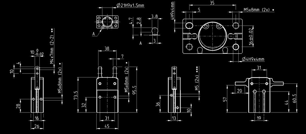
13 Handling Catalogue > > Series CGSN 80 angular grippers CGSN gripper, bore 6 mm - dimensions A = groove for Series CSD sensors * = depth of the mounting threads ** = thread for the accessory mounting *** = opening/closing for air connections Mod. CGSN-6 CGSN gripper, bore 20 mm - dimensions A = groove for Series CSD sensors * = depth of the mounting threads ** = thread for the accessory mounting *** = opening/closing for air connections Mod. CGSN-20 /7.2.05


14 > Series CGSN 80 angular grippers Handling Catalogue > CGSN gripper, bore 25 mm - dimensions A = groove for Series CSD sensors * = depth of the mounting threads ** = thread for the accessory mounting *** = opening/closing for air connections Mod. CGSN-25 CGSN gripper, bore 32 mm - dimensions A = groove for Series CSD sensors * = depth of the mounting threads ** = thread for the accessory mounting *** = opening/closing for air connections Mod. CGSN-32 /
15 Handling Catalogue > > Series CGSN 80 angular grippers Mounting brackets Mod. L-CGP Mod. A B C D E F G H I J K L-CGP ,5 L-CGP ,5 L-CGP ,6 L-CGP ,6 Mounting brackets Mod. C-CGP Mod. A B C D E F G H I J K M C-CGP ,5 6 7 M ,5 6 C-CGP , M ,5 8 C-CGP , M ,6 0 C-CGP , M ,6 2 /
 or L-CGP (male).")
16 > Series CGP parallel grippers Handling Catalogue > Series CGP parallel grippers Magnetic Sizes mm High durability Compact design High gripping force The proximity switches can be inserted in the U-shaped grooves on the body. For an easier installation the gripper can also be equipped with an optional installation adaptor mod. C-CGP (female) or L-CGP (male). Series CGP parallel grippers are available in 5 different sizes. The closing action of the gripper is generated from the cylinder s thrust side, resulting in a higher gripping force. The gripper is equipped with ring bearings in the sliding section for higher durability. Gripper mod. CGP has mounting holes on three sides which provides flexibility in installation. GENERAL DATA Model CGP-0 CGP-6 CGP-20 CGP-25 CGP-32 Bore sizes (mm) Ø 0 Ø 6 Ø 20 Ø 25 Ø 32 Type of operation double-acting Operating pressure.5 7 bar Operating temperature 0 C 80 C Max. operating frequency 80 cycles/min Lubrication lever section - lubrication required on sliding section Opening stroke (mm) Ø 0 = 4 Ø 6 = 8 Ø 20 = 2 Ø 25 = 4 Ø 32 =6 Theoritical holding force - opening (N) Ø 0 = 8 Ø 6 = 24 Ø 20 = 47 Ø 25 = 75 Ø 32 = 00 P = Related to a pressure of 5 bar with gripping point length 3 cm Theoritical holding force - closing (N) Ø 0 = 5 Ø 6 = 8 Ø 25 = 35 Ø 25 = 60 Ø 32 = 85 P = Related to a pressure of 5 bar with gripping point length 3 cm Length of max gripping point L (cm) 3,0 4,0 6,0 7,0 8,5 L = Related to a pressure of 5 bar Weight(g) Ø 0 = 50 Ø 6 = 40 Ø 20 = 250 Ø 25 = 40 Ø 32 = 680 Port sizes M5 (CGP-0 M3) Fluid filtered air, without lubrication. In case lubricated air is used, it is recommended to use oil ISO VG32. Once applied, the lubrication should never be interrupted. /
17 Handling Catalogue > > Series CGP parallel grippers CODING EXAMPLE CGP - 20 CGP SERIES 20 SIZES 0 = ø 0 mm 6 = ø 6 mm 20 = ø 20 mm 25 = ø 25 mm 32 = ø 32 mm PNEUMATIC SYMBOL PNZ PNEUMATIC SYMBOLS The pneumatic symbols which have been indicated in the CODING EXAMPLE are shown below. 652 GRIPPING FORCE CHARACTERISTICS L = Gripping point length F = Gripping Force L = Gripping point length F = Gripping Force /
18 > Series CGP parallel grippers Handling Catalogue > GRIPPING FORCE CHARACTERISTICS L = Gripping point length F = Gripping Force L = Gripping point length F = Gripping Force GRIPPING FORCE CHARACTERISTICS L = Gripping point length F = Gripping Force L = Gripping point length F = Gripping Force /


19 Handling Catalogue > > Series CGP parallel grippers Parallel grippers Series CGP Y = port connection Z = finger mounting-holes X.W.AA = Mounting holes DIMENSIONS Mod. A B C D E F G H I J K L closed L open M N O P Q R S T U V CGP-0 0 5,5 3, , CGP , ,5 58,8 73, ,5 25, CGP , ,5 88, CGP , ,5 79,5 03, CGP , DIMENSIONS Mod. X thread X depth Y thread Y depth W thread W depth Z thread Z depth AA thread AA depth CGP-0 M3 7 M3 - M3 5 M3 - M3 5 CGP-6 M4 M5 - M4 7 M3 - M4 7 CGP-20 M5 3 M5 - M4 8 M4 - M5 8 CGP-25 M6 4 M5 - M6 0 M5 - M6 0 CGP-32 M6 20 M5 - M6 0 M6 - M6 0 /

20 > Series CGP parallel grippers Handling Catalogue > Mounting brackets Mod. L-CGP Mod. A B C D E F G H I J K L-CGP ,5 L-CGP ,5 L-CGP ,6 L-CGP ,6 Mounting brackets Mod. C-CGP Mod. A B C D E F G H I J K M C-CGP ,5 6 7 M ,5 6 C-CGP , M ,5 8 C-CGP , M ,6 0 C-CGP , M ,6 2 /

21 Handling Catalogue > > Series CGPT self-centering parallel grippers with T-guide Series CGPT self-centering parallel grippers with T-guide Single and double acting, magnetic, self-centering Bores: ø 6, 20, 25, 32, 40 mm New Thanks to the use of a high performing and precise force transmission system, the Series CGPT grippers are able to provide high gripping forces while guaranteeing a very high repeatability. The wide range of sizes available allows you to find the best solution for any need of movement. The grippers are supplied with centering bushes (tolerance H8) which, once positioned on the body and/or on the jaws, are able to guarantee, during maintenance, a high interchangeability of the gripper and of the extensions. Robust, compact and light design High closing/opening forces Fixing from the top, from below and from the side Supply on the side or on the bottom (even without using tubes) Self-centering jaws High closing and opening repeatability High interchangeability (centering bushes) Position detection thanks to the use of magnetic proximity switches. In compliance with ROHS directive PTFE, Silicone and Copper free High reliability High resistance to external loads thanks to the T-guide Variants available for use in ATEX zones and for high temperatures GENERAL DATA Type of construction Operation Bores Force transmission Air connections Working pressure Working temperature Store temperature Self-centering parallel gripper with T-guide Single acting (NO, NC), double acting Ø6, 20, 25, 32, 40 mm Lever M3 (Ø6), M5 (Ø20, 25, 32), G/8 (Ø40) 2 8 bar (double acting), 4 8 bar (single acting) 5 C 60 C (standard) - 5 C 50 C (high temperature version) -0 C 80 C Maximum use frequency 3 Hz (ø 6, 20, 25, 32), 2 Hz (ø 40) Repeatability 0.02 mm Interchangeability 0. mm Medium Filtered air in class according to ISO In case lubricated air is used, we recommend ISOVG32 oil and to never interrupt lubrication. Lubrication After 0 million cycles, grease the sliding zones using Molykote DX grease. Protection class Compatibility Certifications Materials IP 40 ROHS Directive ATEX (II 2GD c IIC 20 C(T4)-20 C Ta 80) PTFE, Silicone and Copper free N.B. Pressurize the pneumatic system gradually in order to avoid uncontrolled movements /
22 > Series CGPT self-centering parallel grippers with T-guide Handling Catalogue > CODING EXAMPLE CGPT NC - W EX CGPT SERIES 6 NC W EX BORES: 0 = ø 0 mm 6 = ø 6 mm 20 = ø 20 mm 25 = ø 25 mm 32 = ø 32 mm 40 = ø 40 mm FUNCTIONING: = double acting NO = single acting, normally open NC = single acting, normally closed VERSION: = standard W = high temperatures (50 C) - not magnetic Add EX to order the certified ATEX version PNEUMATIC SYMBOLS PNZ PNZ3 PNZ2 PNEUMATIC SYMBOLS The pneumatic symbols which have been indicated in the CODING EXAMPLE are shown below. Maximum admissible loads and torques Fz s, Mx s, My s, Mz s = maximum admissible loads and torques in static conditions Fz d, Mx d, My d, Mz d = maximum admissible loads and torques in dynamic conditions Mod. Fz s (N) Mx s (Nm) My s (Nm) Mz s (Nm) Fz d (N) Mx d (Nm) My d (Nm) Mz d (Nm) CGPT CGPT CGPT CGPT CGPT /
23 Handling Catalogue > > Series CGPT self-centering parallel grippers with T-guide Series CGPT grippers - construction LIST OF COMPONENTS PARTS MATERIALS - Body Aluminium 2 - Jaw Stainless steel 3 - Piston Stainless steel 4 - Seals HNBR / FKM 5 - Centering bushes Stainless steel 6 - Levers Steel 7 - End cover Aluminium 8 - Spring Stainless steel 9 - Magnet Neodymium 0 - Cover Stainless steel /

 Repeatability (mm) Max use frequency (Hz) CGPT-6 57 65 2.5 9 2 8 5 60 0.02 3 0.09 CGPT-6-NC 7 45 2.")
24 > Series CGPT self-centering parallel grippers with T-guide Handling Catalogue > CGPT gripper, size 6 mm - dimensions DRAWING LEGEND: A = Opening of air connection B = Closing of air connection C = Closed gripper D = Open gripper Mod. Closing gripping force each jaw at 6 bar (N) Opening gripping force each jaw at 6 bar (N) Stroke per jaw (mm) Air consumption per cycle (Ncm³) Working pressure (bar) Working temperature ( C) Repeatability (mm) Max use frequency (Hz) CGPT CGPT-6-NC (single-acting), 9 (double-acting) CGPT-6-NO (single-acting), 9 (double-acting) Weight (Kg) /
25 Handling Catalogue > > Series CGPT self-centering parallel grippers with T-guide CGPT gripper, size 20 mm - dimensions DRAWING LEGEND: A = Opening of air connection B = Closing of air connection C = Closed gripper D = Open gripper Mod. Closing gripping force each jaw at 6 bar (N) Opening gripping force each jaw at 6 bar (N) Stroke per jaw (mm) Air consumption per cycle (Ncm³) Working pressure (bar) Working temperature ( C) Repeatability (mm) Max use frequency (Hz) CGPT CGPT-20-NC (single-acting), 20 (double-acting) CGPT-20-NO (single-acting), 20 (double-acting) Weight (Kg) /
26 > Series CGPT self-centering parallel grippers with T-guide Handling Catalogue > CGPT gripper, size 25 mm - dimensions DRAWING LEGEND: A = Opening of air connection B = Closing of air connection C = Closed gripper D = Open gripper Mod. Closing gripping force each jaw at 6 bar (N) Opening gripping force each jaw at 6 bar (N) Stroke per jaw (mm) Air consumption per cycle (Ncm³) Working pressure (bar) Working temperature ( C) Repeatability (mm) Max use frequency (Hz) CGPT CGPT-25-NC (single-acting), 45 (double-acting) CGPT-25-NO (single-acting), 45 (double-acting) Weight (Kg) /
27 Handling Catalogue > > Series CGPT self-centering parallel grippers with T-guide CGPT gripper, size 32 mm - dimensions DRAWING LEGEND: A = Opening of air connection B = Closing of air connection C = Closed gripper D = Open gripper Mod. Closing gripping force each jaw at 6 bar (N) Opening gripping force each jaw at 6 bar (N) Stroke per jaw (mm) Air consumption per cycle (Ncm³) Working pressure (bar) Working temperature ( C) Repeatability (mm) Max use frequency (Hz) CGPT CGPT-32-NC (single-acting), 0 (double-acting) CGPT-32-NO (single-acting), 0 (double-acting) Weight (Kg) /

28 > Series CGPT self-centering parallel grippers with T-guide Handling Catalogue > CGPT gripper, size 40 mm - dimensions DRAWING LEGEND: A = Opening of air connection B = Closing of air connection C = Closed gripper D = Open gripper Mod. Closing gripping force each jaw at 6 bar (N) Opening gripping force each jaw at 6 bar (N) Stroke per jaw (mm) Air consumption per cycle (Ncm³) Working pressure (bar) Working temperature ( C) Repeatability (mm) Max use frequency (Hz) CGPT CGPT-40-NC (single-acting), 202 (double-acting) CGPT-40-NO (single-acting), 202 (double-acting) Weight (Kg) /
29 Handling Catalogue > > Series CGPT self-centering parallel grippers with T-guide GRIPPING FORCE (Fc) PER SINGLE JAW The total gripping force has to be calculated as follows: Total Fc = Fc x 2 Gripping force in relation to the lever arm (R) and the eccentricity (b, e) R = (b² + e²) CGPT-6 R = lever arm Fc = closing gripping force Fa (opening gripping force) = Fc + 0% CGPT-20 R = lever arm Fc = closing gripping force Fa (opening gripping force) = Fc + 0% CGPT-25 R = lever arm Fc = closing gripping force Fa (opening gripping force) = Fc + 0% /
30 > Series CGPT self-centering parallel grippers with T-guide Handling Catalogue > GRIPPING FORCE (Fc) PER SINGLE JAW CGPT-32 R = lever arm Fc = closing gripping force Fa (opening gripping force) = Fc + 0% CGPT-40 R = lever arm Fc = closing gripping force Fa (opening gripping force) = Fc + 0% /
31 Handling Catalogue > > Series CGPT self-centering parallel grippers with T-guide Examples of mounting Mod. A B C D E F CGPT-6 Ø5 M3 M2.5 M2.5 Ø4 M2.5 CGPT-20 Ø6 M4 M3 M3 Ø5 M3 CGPT-25 Ø8 M5 M4 M4 Ø6 M4 CGPT-32 Ø8 M5 M4 M5 Ø8 M5 CGPT-40 Ø0 M6 M5 M6 Ø0 M6 /
32 > Series CGPT self-centering parallel grippers with T-guide Handling Catalogue > Air supply ports Mod. G H I CGPT-6 M3 M2 OR x2.5 CGPT-20 M5 M2 OR x2.5 CGPT-25 M5 M2 OR x2.5 CGPT-32 M5 M3 OR x3.5 CGPT-40 G/8 M3 OR x3.5 Example of use of the pressurization/lubrication hole Example of use of the lubrication (greasing) or pressurization hole of the zone with moving items NOTE : grease the sliding zones using Molykote DX grease. NOTE 2: supply a pressure of max. 3 bar in order to avoid the sudden ejection of grease. Mod. CGPT-6 CGPT-20 CGPT-25 CGPT-32 CGPT-40 X M3 M5 M5 M5 M5 Example of mounting: sensors L = sensor mod. CSD-332 or mod. CSD-362 In order to position the sensor correctly, a channel must be created in the base. Mod. CGPT-6 CGPT-20 CGPT-25 CGPT-32 CGPT-40 /
33 Handling Catalogue > > Series CGPT self-centering parallel grippers with T-guide Series CSD magnetic proximity switches with 3-wire cable Mod. Operation Connections Voltage Output Max. current Max Load Protection L = length cable CSD-332 Electronic 3 wires 0 27 V DC PNP 200 ma 6W Against polarity reversing and overvoltage 2 m Series CSD magnetic proximity switches with male connector M8 Length of cable 0.3 metres Mod. Operation Connections Voltage Output Max. current Max Load Protection CSD-362 Electronic 3 wires with M8 connector 0 27 V DC PNP 200 ma 6W Against polarity reversing and overvoltage /

34 > Series CGPS self-centering parallel grippers Handling Catalogue > Series CGPS self-centering parallel grippers with double ball bearing guide Single and double acting, magnetic, self-centering Bores: Ø 0, 6, 20, 25, 32 mm New Thanks to the use of a high performing and precise force transmission system and to the double ball bearing guide, the Series CGPS grippers are able to provide high gripping forces while guaranteeing a very high repeatability and robustness (resistance to external static and dynamic loads). The wide range of sizes available allows you to find the best solution for any need of movement. The grippers can be supplied with bushes and centering plugs (tolerance H8) which, once positioned on the body and/or on the jaws, are able to guarantee, during maintenance, a high interchangeability of the gripper and of the extensions. Robust, compact and light design High closing/opening forces Fixing from below and from the side Supply on the side Self-centering jaws High closing and opening repeatability High interchangeability (bushes and centering plugs) Position detection (front and side) thanks to the use of Series CSD magnetic proximity switches In compliance with ROHS directive Finger types available: long with through-holes and flat with threaded holes High resistance to external loads thanks to the double ball bearing guide Variants available: for use in ATEX zones and for high temperatures GENERAL DATA Type of construction Operation Bores Force transmission Air connections Working pressure Working temperature Store temperature Maximum use frequency Repeatability Interchangeability Medium Compatibility Certifications Materials Suitable magnetic switches Self-centering parallel gripper with double ball bearing guide Single acting (NO, NC), double acting Ø 0, 6, 20, 25, 32 mm Lever M5 2 8 bar (double acting), 4 8 bar (single acting) 5 C 60 C (standard) - 5 C 50 C (high temperature version) -0 C 80 C 3 Hz 0.02 mm 0. mm Filtered air in class according to ISO In case lubricated air is used, we recommend ISOVG32 oil and to never interrupt lubrication. ROHS Directive ATEX (II 2GD c IIC 20 C(T4)-20 C Ta 80) PTFE, Silicone and Copper free Mod. CSD-332, CSD-362 NOTE: Pressurize the pneumatic system gradually in order to avoid uncontrolled movements /
35 Handling Catalogue > > Series CGPS self-centering parallel grippers CODING EXAMPLE CGPS - L NO - W EX CGPS SERIES L 6 NO W EX DESIGN TYPE: L = Long finger F = Flat finger BORES: 0 = ø 0 mm 6 = ø 6 mm 20 = ø 20 mm 25 = ø 25 mm 32 = ø 32 mm FUNCTIONING: = double acting NO = single acting, normally open NC = single acting, normally closed VERSION: = standard W = high temperatures (50 C) Add EX to order the certified ATEX version PNEUMATIC SYMBOLS PNZ PNZ3 PNZ2 PNEUMATIC SYMBOLS The pneumatic symbols which have been indicated in the CODING EXAMPLE are shown below. Maximum admissible loads and torques /
36 > Series CGPS self-centering parallel grippers Handling Catalogue > Series CGPS grippers - construction LIST OF COMPONENTS PARTS MATERIALS - Body Aluminium 2 - Jaw Stainless steel 3 - Piston Stainless steel 4 - Seals HNBR / FKM 5 - Ball bearings end cap Stainless steel 6 - Slide ball bearings Steel 7 - Levers Steel 8 - Rear end-stroke Pom (Acetal) 9 - Spring Stainless steel 0 - Ball bearings guide Stainless steel - Jaws end cap Steel 2 - Magnet Plastoferrite /

37 Handling Catalogue > > Series CGPS self-centering parallel grippers CGPS gripper, size 0 mm - dimensions DRAWING LEGEND: A = Opening of air connection B = Closing of air connection C = Closed gripper D = Open gripper Mod. Closing gripping force each jaw at 6 bar (N) Opening gripping force each jaw at 6 bar (N) Stroke per jaw (mm) Air consumption per cycle (Ncm³) Working pressure (bar) Working temperature ( C) Repeatability (mm) Max use frequency (Hz) CGPS-L / CGPS-F / CGPS-L-0-NC / CGPS-F-0-NC / CGPS-L-0-NO / CGPS-F-0-NO / Weight (Kg) /

 Max use frequency (Hz) CGPS-L-6 49 60 3 7.8 2 8 5 60 +/- 0.02 3 0.27 CGPS-F-6 49 60 3 7.8 2 8 5 60 +/- 0.02 3 0.30 CGPS-L-6-NC 57.7 47.5 3 4.2 4 8 5 60 +/- 0.02 3 0.29 CGPS-F-6-NC 57.")
38 > Series CGPS self-centering parallel grippers Handling Catalogue > CGPS gripper, size 6 mm - dimensions DRAWING LEGEND: A = Opening of air connection B = Closing of air connection C = Closed gripper D = Open gripper Mod. Closing gripping force each jaw at 6 bar (N) Opening gripping force each jaw at 6 bar (N) Stroke per jaw (mm) Air consumption per cycle (Ncm³) Working pressure (bar) Working temperature ( C) Repeatability (mm) Max use frequency (Hz) CGPS-L / CGPS-F / CGPS-L-6-NC / CGPS-F-6-NC / CGPS-L-6-NO / CGPS-F-6-NO / Weight (Kg) /

39 Handling Catalogue > > Series CGPS self-centering parallel grippers CGPS gripper, size 20 mm - dimensions DRAWING LEGEND: A = Opening of air connection B = Closing of air connection C = Closed gripper D = Open gripper Mod. Closing gripping force each jaw at 6 bar (N) Opening gripping force each jaw at 6 bar (N) Stroke per jaw (mm) Air consumption per cycle (Ncm³) Working pressure (bar) Working temperature ( C) Repeatability (mm) Max use frequency (Hz) CGPS-L / CGPS-F / CGPS-L-20-NC / CGPS-F-20-NC / CGPS-L-20-NO / CGPS-F-20-NO / Weight (Kg) /

 Max use frequency (Hz) CGPS-L-25 25 37 7 44.9 2 8 5 60 +/- 0.02 3 0.447 CGPS-F-25 25 37 7 44.9 2 8 5 60 +/- 0.02 3 0.464 CGPS-L-25-NC 43.2 7 24. 4 8 5 60 +/- 0.02 3 0.456 CGPS-F-25-NC 43.")
40 > Series CGPS self-centering parallel grippers Handling Catalogue > CGPS gripper, size 25 mm - dimensions DRAWING LEGEND: A = Opening of air connection B = Closing of air connection C = Closed gripper D = Open gripper Mod. Closing gripping force each jaw at 6 bar (N) Opening gripping force each jaw at 6 bar (N) Stroke per jaw (mm) Air consumption per cycle (Ncm³) Working pressure (bar) Working temperature ( C) Repeatability (mm) Max use frequency (Hz) CGPS-L / CGPS-F / CGPS-L-25-NC / CGPS-F-25-NC / CGPS-L-25-NO / CGPS-F-25-NO / Weight (Kg) /

 Max use frequency (Hz) CGPS-L-32 95 237 0 04.6 2 8 5 60 +/-0.02 2 0.729 CGPS-F-32 95 237 0 04.6 2 8 5 60 +/-0.02 2 0.753 CGPS-L-32-NC 22 20 0 56.2 4 8 5 60 +/-0.02 2 0.742 CGPS-F-32-NC 22 20 0 56.")
41 Handling Catalogue > > Series CGPS self-centering parallel grippers CGPS gripper, size 32 mm - dimensions DRAWING LEGEND: A = Opening of air connection B = Closing of air connection C = Closed gripper D = Open gripper Mod. Closing gripping force each jaw at 6 bar (N) Opening gripping force each jaw at 6 bar (N) Stroke per jaw (mm) Air consumption per cycle (Ncm³) Working pressure (bar) Working temperature ( C) Repeatability (mm) Max use frequency (Hz) CGPS-L / CGPS-F / CGPS-L-32-NC / CGPS-F-32-NC / CGPS-L-32-NO / CGPS-F-32-NO / Weight (Kg) /
42 > Series CGPS self-centering parallel grippers Handling Catalogue > GRIPPING FORCE (Fc) PER SINGLE JAW The total gripping force has to be calculated as follows: Total Fc = Fc x 2 Gripping force in relation to the lever arm (R) and the eccentricity (b, e) R = (b² + e²) CGPS-..-0 R = lever arm Fc = closing gripping force Fa (opening gripping force) = Fc + 0% CGPS-..-6 R = lever arm Fc = closing gripping force Fa (opening gripping force) = Fc + 0% CGPS R = lever arm Fc = closing gripping force Fa (opening gripping force) = Fc + 0% /
43 Handling Catalogue > > Series CGPS self-centering parallel grippers GRIPPING FORCE (Fc) PER SINGLE JAW CGPS R = lever arm Fc = closing gripping force Fa (opening gripping force) = Fc + 0% CGPS R = lever arm Fc = closing gripping force Fa (opening gripping force) = Fc + 0% /
44 > Series CGPS self-centering parallel grippers Handling Catalogue > Examples of mounting Mod. B C D E Centering ring F G H I L CGPS-..-0 Ø2 Ø M3 Ø5 TR-CG-05 M3 M2.5 M2.5 M2.5 Ø.5 CGPS-..-6 Ø3 Ø7 M4 Ø6 TR-CG-06 M4 M3 M3 M3 Ø2 CGPS Ø4 Ø2 M5 Ø8 TR-CG-08 M5 M4 M4 M4 Ø2.5 CGPS Ø4 Ø26 M6 Ø0 TR-CG-0 M6 M5 M5 M5 Ø3 CGPS Ø5 Ø34 M6 Ø0 TR-CG-0 M6 M5 M6 M6 Ø4 /


45 Handling Catalogue > > Series CGPS self-centering parallel grippers Centering ring Mod. TR-CG Supplied with: 2x centering rings in steel Mod. M (h8) N P TR-CG-04 Ø4 Ø TR-CG-05 Ø5 Ø3. 3 TR-CG-06 Ø6 Ø4. 4 TR-CG-08 Ø8 Ø5. 5 TR-CG-0 Ø0 Ø6. 6 Air supply ports Mod. CGPS-..-0 CGPS-..-6 CGPS CGPS CGPS A M3 M5 M5 M5 M5 Example of mounting: sensors Z = sensor mod. CSD-332 or mod. CSD-362 In order to position the sensor correctly, a channel must be created in the base. Mod. R S T V CGPS CGPS CGPS CGPS CGPS /
46 > Series CGPS self-centering parallel grippers Handling Catalogue > Series CSD magnetic proximity switches with 3-wire cable Mod. Operation Connections Voltage Output Max. current Max Load Protection L = length cable CSD-332 Electronic 3 wires 0 27 V DC PNP 200 ma 6W Against polarity reversing and overvoltage 2 m Series CSD magnetic proximity switches with male connector M8 Length of cable 0.3 metres Mod. Operation Connections Voltage Output Max. current Max Load Protection CSD-362 Electronic 3 wires with M8 connector 0 27 V DC PNP 200 ma 6W Against polarity reversing and overvoltage /

47 Handling Catalogue > > Series CGLN wide opening parallel grippers Series CGLN wide opening parallel grippers New version Bores: ø mm High installation versatility Rack and pinion synchronized mechanism Sturdy and accurate construction Series CGLN s double piston ensures a high gripping force from within a compact unit. The body of the gripper is complete of grooves to mount magnetic proximity switches (Series CSC). The wide range of bores and strokes available allows to meet technical requirements at its best. Repositioning of the gripper is made easier by the 2 calibrated holes provided in the jaws and by the 2 locating pins in the base. GENERAL DATA Operation double effect Working pressure 2 8 bar (3 8 bar for Ø0) Working temperature 5 C 60 C Lubrification not required Repeatibility ± 0. mm Effective gripping force with pressure = 0.5MPa and gripping moment R = 40 mm ( Ø ) or = 80 mm ( Ø 32 ) Air ports Fluid Ø 0 = 5N Ø 6 = 45N Ø 20 = 75N Ø 25 = 25N Ø 32 = 225N Ø = M5 Ø 32 = G/8 filtered air, without lubrication. If lubricated air is used, it is recommended to use oil ISO VG32. Once applied, the lubrication should never be interrupted. /
48 > Series CGLN wide opening parallel grippers Handling Catalogue > CODING EXAMPLE CGLN CGLN SERIES SIZES: 0 = ø 0 mm 6 = ø 6 mm 20 = ø 20 mm 25 = ø 25 mm 32 = ø 32 mm STROKE PNEUMATIC SYMBOL PNZ PNEUMATIC SYMBOLS The pneumatic symbols which have been indicated in the CODING EXAMPLE are shown below. /
49 Handling Catalogue > > Series CGLN wide opening parallel grippers Series CGLN Gripper - construction LIST OF COMPONENTS PARTS MATERIALS - Bushing Bronce 2 - Body Aluminium 3 - Rack Stainless steel 4 - Fixing screw Steel 5 - Gripping flange Aluminium 6 - Buffer seal PU 7 - Piston seal NBR 8 - Rod seal NBR 9 - Magnet Plastoferrite 0 - Pinion Steel - Piston Aluminium 2 - Rod Stainless steel 3 - Rod-piston Stainless steel 4 - Plug Aluminium 5 - Header Steel /
50 > Series CGLN wide opening parallel grippers Handling Catalogue > Sizing criteria: ) GRIPPING FORCE ANALYSIS The selection of the size of the gripper has to be carried out according to the weight of the object that has to be moved. It is strongly recommended to select a gripper bore able to develop a gripping force at least 20 times higher than the weight of the object. In case of great acceleration or impact during the moving of the object, it is necessary to increase the factor of safety. EXAMPLE OF CALCULATION (see the diagram on the right) Size of the object to be moved (side x side) = 200 m x 20 mm Weight of the object to be moved (Kg) = 0.3 Factor of safety = 20 Gripping moment R (mm) = 70 Working pressure (MPa) = 0.5 Minimum required gripping force Fmin = 0.3kg x 20 x 9.8m/s² = 60N Through the diagrams Effective Gripping force we deduce from the above mentioned conditions that the gripping force with the mod. CGLN-20 is 73N, that is 24 times the weight of the object. The condition requiring that gripping force is at least 20 times higher than the set gripping force is thus satisfied. Once the gripper size is chosen, select a stroke that allows to have a maximum opening which is wider than the size of the object to be moved. In the case above the gripper CGLN is the right choice. F = 220 mm > 200 mm ACTUAL GRIPPING FORCE (F) The shown gripping force corresponds to the gripping force of a finger when all fingers (or accessories) are in contact with the load. F = Pushing force of finger Sizing criteria: 2) GRIPPING DISTANCE ANALYSIS The R gripping distance of the object has to meet the parameters of the lines of force which are indicated for each pressure in the diagrams Effective grip force. If the R distance is exceeded, the load applied will be too much overhanging, thus causing the screws to loosen as well as a reduced component life. R = gripping distance (mm) /
51 Handling Catalogue > > Series CGLN wide opening parallel grippers Gripping force for bore 0 CGLN F = Gripping force (N) R = Gripping moment (mm) CGLN and CGLN F = Gripping force (N) R = Gripping moment (mm) Gripping force for bore 6 CGLN F = Gripping force (N) R = Gripping moment (mm) CGLN and CGLN F = Gripping force (N) R = Gripping moment (mm) /
52 > Series CGLN wide opening parallel grippers Handling Catalogue > Gripping force for bore 20 CGLN F = Gripping force (N) R = Gripping moment (mm) CGLN and CGLN F = Gripping force (N) R = Gripping moment (mm) Gripping force for bore 25 CGLN F = Gripping force (N) R = Gripping moment (mm) CGLN and CGLN F = Gripping force (N) R = Gripping moment (mm) /
53 Handling Catalogue > > Series CGLN wide opening parallel grippers Gripping force for bore 32 CGLN F = Gripping force (N) R = Gripping moment (mm) CGLN and CGLN F = Gripping force (N) R = Gripping moment (mm) /


54 > Series CGLN wide opening parallel grippers Handling Catalogue > CGLN gripper, bore 0 mm - dimensions DRAWING LEGEND: * = depth of the mounting threads ** = thread for the accessory mounting *** = opening/closing of air connections Mod. Bore Total stroke A B C D E (Closed) Min opening F (Open) Max opening G Max frequency (cycles/min) Weight (g) CGLN CGLN CGLN /
55 Handling Catalogue > > Series CGLN wide opening parallel grippers CGLN gripper, bore 6 mm - dimensions DRAWING LEGEND: * = depth of the mounting threads ** = thread for the accessory mounting *** = opening/closing of air connections Mod. Bore Total stroke A B C D E (Closed) Min opening F (Open) Max opening G Max frequency (cycles/min) Weight (g) CGLN CGLN CGLN /
56 > Series CGLN wide opening parallel grippers Handling Catalogue > CGLN gripper, bore 20 mm - dimensions DRAWING LEGEND: * = depth of the mounting threads ** = thread for the accessory mounting *** = opening/closing of air connections Mod. Bore Total stroke A B C D E (Closed) Min opening F (Open) Max opening G Max frequency (cycles/min) Weight (g) CGLN CGLN CGLN /
57 Handling Catalogue > > Series CGLN wide opening parallel grippers CGLN gripper, bore 25 mm - dimensions DRAWING LEGEND: * = depth of the mounting threads ** = thread for the accessory mounting *** = opening/closing of air connections Mod. Bore Total stroke A B C D E (Closed) Min opening F (Open) Max opening G Max frequency (cycles/min) Weight (g) CGLN CGLN CGLN /
58 > Series CGLN wide opening parallel grippers Handling Catalogue > CGLN gripper, bore 32 mm - dimensions DRAWING LEGEND: * = depth of the mounting threads ** = thread for the accessory mounting *** = opening/closing of air connections Mod. Bore Total stroke A B C D E (Closed) Min opening F (Open) Max opening G Max frequency (cycles/min) Weight (g) CGLN CGLN CGLN /

59 Handling Catalogue > > Series CGC 3-Finger grippers, centric Series CGC 3-Finger centric grippers Magnetic Sizes Compact design High gripping force Long stroke The proximity switches can be inserted in the U-shaped grooves on the body in order to detect whether the gripper is in an open or closed position. Series CGC 3-finger centric grippers are available in 5 different sizes. Significant for Series CGC is the compact design that allows the combination of a high gripping force and long stroke. The piston is equipped with a permanent magnet for the use of magnetic proximity switches. GENERAL DATA Model CGC-50; CGC-64; CGC-80; CGC-00; CGC-25 Bore sizes Ø 32 Ø 45 Ø 58 Ø 77 Ø 98 Type of operation double-acting Materials housing: high tensile special hard-coated aluminium alloy, Functional parts: hardened steel Operating pressure (bar) 2 7 bar Operating temperature 5 C 60 C Repeatability +/- 0,05 mm Max. operating frequency 60 cycles/min Lubrication lever section lubrication required on sliding section Theoretical holding force (N) with gripping point at 30 mm with 5 bar opening Theoretical holding force (N) with gripping point at 30 mm with 5 bar closing Ø 32 = 78, Ø 45 = 85 Ø 58 = 340, Ø77 = 580 Ø 98 = 940 Ø 32 = 68, Ø 45 = 60 Ø 58 =290, Ø 77= 50 Ø 98 = 860 Weight (g) Ø 32 = 230, Ø 45 = 40 Ø 58 = 800, Ø 77= 400 Ø 98 = 2400 Stroke per finger (mm) Ø 32 = 4, Ø 45 = 6 Ø 58 = 8, Ø 77 = 0 Ø 98 = 3 Port sizes Ø M5 Ø 77 - Ø 98 -G/8 Fluid filtered air without lubrication. If lubricated air is used, it is recommended to use oil ISO VG32. Once applied, the lubrication should never be interrupted. /
60 > Series CGC 3-Finger grippers, centric Handling Catalogue > CODING EXAMPLE CGC CGC SERIES 050 SIZE 050 = 32 mm 064 = 45 mm 080 = 58 mm 00 = 77 mm 25 = 98 mm PNEUMATIC SYMBOL PNZ PNEUMATIC SYMBOLS The pneumatic symbols which have been indicated in the CODING EXAMPLE are shown below. 652 GRIPPING FORCE CHARACTERISTICS F = Gripping Force L = Gripping point length /
61 Handling Catalogue > > Series CGC 3-Finger grippers, centric GRIPPING FORCE CHARACTERISTICS F = Gripping Force L = Gripping point length F = Gripping Force L = Gripping point length GRIPPING FORCE CHARACTERISTICS F = Gripping Force L = Gripping point length F = Gripping Force L = Gripping point length /


62 > Series CGC 3-Finger grippers, centric Handling Catalogue > Grippers Series CGC TT = port connection QQ = finger mounting holes RR = Mounting holes S = Mounting holes DIMENSIONS Mod. A B C CC D E F G H I K L M N N2 RR QQ S TT U X Y Z Weight (g) CGC ,5 30, , ,5 Ø 3,4 M3x0,5 Ø 3 M5 Ø CGC , ,2 0 6 Ø 5,5 M4x0,7 Ø 4 M5 Ø 4 2 2, CGC , , , Ø 6,6 M5x0,8 Ø 5 M5 Ø CGC , , Ø 6,6 M6x Ø 5 PT /8 Ø CGC ,5 78, , ,2 3,5 27,5 Ø 9 M6x Ø 6 PT /8 Ø 6 3 3, Support dimensions for grippers Series CGC Dimensions of external mounting support of finger - gripping element Mod. L L2 L3 L4 L5 L6 L7 L8 L9 L0 CGC CGC CGC CGC /


63 Handling Catalogue > > Series RPGA sprue grippers Series RPGA sprue grippers Size 20mm New version Angular, not self-centering, single-acting, Normally Open Models: Flat Finger, Curved Finger, Short Finger, Flat Finger with sensor slot, Curved Finger with sensor slot Thanks to a piston with a size of 20mm and to the direct transfer of the force from the piston to the fingers, Series RPGA guarantees a strong and a safe grip. Their technical features ensure a high gripping force and make these grippers particularly suitable in the removal of injection molded items. The surface treatments on each metallic part make this series very wear resistant. D and E models are provided with a finger having a slot for the installation of an inductive sensor. GENERAL DATA Operation single-acting, Normally Open Materials anodized aluminium body and fingers, PU seals Working pressure 2.5 bar 8 bar Working temperature 0 C 60 C Max frequency 2.5 Hz Lubrication Not necessary Air ports G/8 Media Filtered air, without lubrication Size 20 mm Weights 20 g (models A and B); 25 g (models C, D, E) Gripping torque at 6 bar 30 Ncm Opening torque at 6 bar 25 Ncm Gripping force at 6 bar 90 N Closing time without load 20 ms Opening time 75 ms /

64 > Series RPGA sprue grippers Handling Catalogue > CODING EXAMPLE RPGA A RPGA SERIES 20 A SIZE: 20 = ø 20 mm TYPE OF CONSTRUCTION: A = Flat finger B = Curved finger C = Short finger with mounting holes for extensions D = Flat finger for sensor E = Curved finger for sensor Flat finger gripper Mod. RPGA-20-A - dimensions Mod. RPGA-20-A A = connection port B = fixing thread /


65 Handling Catalogue > > Series RPGA sprue grippers Curved finger gripper Mod. RPGA-20-B - dimensions Mod. RPGA-20-B A = connection port B = fixing thread Short finger gripper Mod. RPGA-20-C - dimensions Mod. RPGA-20-C A = connection port B = fixing thread C = fixing holes /


66 > Series RPGA sprue grippers Handling Catalogue > Flat finger gripper with sensor slot Mod. RPGA-20-D - dimensions Note: the sensor is not supplied with the gripper Mod. RPGA-20-D A = connection port B = fixing thread C = sensor fixing hole Curved finger gripper with sensor slot Mod. RPGA-20-E - dimensions Note: the sensor is not supplied with the gripper Mod. RPGA-20-E A = connection port B = fixing thread C = sensor fixing hole /

67 Handling Catalogue > > Series RPGB sprue grippers Series RPGB sprue grippers Size 8, 2mm New version Angular, not self-centering, single-acting, Normally Open Models: Flat Finger, Short Finger, Flat Finger with sensor Suitable for plastic injection molding sector Easy to install Compact and lightweight Wear resistant Models RPGB-08-D and RPGB-2-D are supplied with sensor CSD-362 already mounted The external design, the choice of materials and the search for miniaturization makes Series RPGB a compact and lightweight solution. The D model is provided with a finger having a slot for the installation of a magnetic sensor which is able to detect the grip of the piece. Its technical features ensure a high gripping force and make this gripper particularly suitable in the removal of injection molded items. The surface treatments on each metallic part make this series very wear resistant. GENERAL DATA Operation single-acting, Normally Open Materials anodized aluminium body and fingers, HNBR seals Working pressure 2.5 bar 8 bar Working temperature 0 C 60 C Max frequency 3 Hz Lubrication Not necessary Air ports M5 Media Filtered air, class according to ISO 8573-, without lubrication Size 8, 2 mm Weights 5 g (size 8) - 50 g (size 2) Gripping torque at 6 bar Opening torque at 6 bar Gripping force at 6 bar Closing time without load Opening time 25 Ncm (size 8) - 90 Ncm (size 2) 2 Ncm (size 8) - 5 Ncm (size 2) 7 N (size 8) - 30 N (size 2) 0 ms 30 ms /
68 > Series RPGB sprue grippers Handling Catalogue > CODING EXAMPLE RPGB A RPGB SERIES 2 A SIZE: 08 = ø 8 mm 2 = ø 2 mm TYPE OF CONSTRUCTION: A = Flat finger C = Short finger with mounting holes for extensions D = Flat finger with sensor mounted (Mod. CSD-362) /


69 Handling Catalogue > > Series RPGB sprue grippers Flat finger gripper Mod. RPGB-08-A - dimensions Mod. RPGB-08-A A = port connection B = mounting hole Short finger gripper Mod. RPGB-08-C - dimensions Mod. RPGB-08-C A = port connection B = mounting hole C = mounting thread /


70 > Series RPGB sprue grippers Handling Catalogue > Flat finger gripper with sensor slot Mod. RPGB-08-D - dimensions This model is supplied with sensor CSD-362 mounted. Mod. RPGB-08-D A = connection port B = mounting hole C = sensor groove Flat finger gripper Mod. RPGB-2-A - dimensions Mod. RPGB-2-A A = port connection B = mounting holes /


71 Handling Catalogue > > Series RPGB sprue grippers Short finger gripper Mod. RPGB-2-C - dimensions Mod. RPGB-2-C A = port connection B = mounting holes C = mounting thread Flat finger gripper with sensor slot Mod. RPGB-2-D - dimensions This model is supplied with sensor CSD-362 mounted. Mod. RPGB-2-D A = port connection B = mounting hole C = sensor groove /


72 > Series RPGB sprue grippers Handling Catalogue > Series CSD magnetic proximity switches with 3-wire cable Mod. Operation Connections Voltage Output Max. current Max Load Protection L = length cable CSD-332 Electronic 3 wires 0 27 DC PNP 200 ma 6W Against polarity reversing and overvoltage 2 m Series CSD magnetic proximity switches with male connector M8 Length cable 0,3 mt. Mod. Operation Connections Voltage Output Max. current Max Load Protection CSD-362 Electronic 3 wires with M8 connector 0 27 DC PNP 200 ma 6W Against polarity reversing and overvoltage /
73 Handling Catalogue > > Series RPGB sprue grippers Extension with connector M8, 3 Pin Male / Female Non shielded Mod. cable length A (m) CS-DW03HB-C250 2,5 CS-DW03HB-C500 5 Circular connectors M8, 3 Pin Female With PU sheathing, non shielded cable. Protection class: IP65 BN = Brown BK = Black BU = Blue Mod. L = cable length (m) CS-2 2 CS-5 5 CS-0 0 /

74 The Camozzi worldwide network To respond and act quickly PRESENCE ON EVERY CONTINENT 23 SUBSIDIARIES 55 EXCLUSIVE DISTRIBUTORS To understand markets and the small but important differences between them, a company cannot only rely on the essential digital tools we all use every day, but it needs to be locally present, face to face, able to look into people s eyes and speak their language. This is why Camozzi now has an international network, based in Italy, but present on every continent. 6 PRODUCTION FACILITIES OVER 200 EMPLOYEES ITALY HEADQUARTERS CAMOZZI SPA 72 SUBSIDIARIES AND PRODUCTION FACILITIES COUNTRY WITH EXCLUSIVE DISTRIBUTORS

75


76 Catalogue Handling MIX COMUNICAZIONE - MI Contacts Camozzi spa Società Unipersonale Via Eritrea, 20/I 2526 Brescia - Italy Tel Fax info@camozzi.com Technical assistance Catalogue product inquiries and requests for support: Tel service@camozzi.com Special product inquiries: Tel service@camozzi.com Worldwide sales network Camozzi Subsidiaries and Exclusive Distributors To check our sales network, visit the Camozzi website at Contacts / Camozzi Worldwide GB082 0/206 Air that moves the world A Camozzi Group Company
Single and double acting, magnetic, self-centering Bores: ø 16, 20, 25, 32, 40 mm
 > Series CGPT self-centering parallel grippers with T-guide Series CGPT self-centering parallel grippers with T-guide Single and double acting, magnetic, self-centering Bores: ø 6, 20, 25, 32, 40 mm New
Bores: ø 10, 16, 20, 25, 32 mm
 > Series CGLN wide opening parallel grippers CATALOGUE > Release 8.8 Series CGLN wide opening parallel grippers New version Bores: ø 0, 6, 20, 25, 32 mm»» High installation versatility»» Rack and pinion
Wide opening parallel grippers Series CGLN
 CATALOGUE > s 202 Wide opening parallel grippers Series CGLN > Grippers Series CGLN Magnetic Sizes: ø 0-6 - 20-25 - 32 mm» High flexibility during mounting» High grip force» Rack and pinion synchronized
Series CGZT three-jaw grippers with T-guide
 Series CGZT three-jaw grippers with T-guide New Single and double acting, magnetic, self-centering Sizes: 40, 50, 64, 80, 100, 125, 160 mm The new Series CGZT pneumatic grippers, thanks to the use of a
Series CGCN self-centering three-jaw grippers with T-guide
 HANDLING AND VACUUM 2019 GRIPPERS > Series CGCN self-centering three-jaw grippers with T-guide New Double acting, magnetic Sizes: 50, 64, 80, 100, 125 mm The new Series CGCN pneumatic grippers are available
GRIPPERS SERIES P3 - P12 ACTUATORS
 GRIPPERS SERIES P3 - P12 1 GRIPPER WITH TWO PARALLEL JAWS, SERIES P3 GRIPPER WITH TWO PARALLEL JAWS, SERIES P3 Parallel double-acting two-jaw gripper, with either internal or external clamping. Aluminum
2-JAW SELF-CENTERING PARALLEL PNEUMATIC GRIPPER (SERIES HS)
") HS 2-JAW SELF-CENTERING PARALLEL PNEUMATIC GRIPPER (SERIES HS) Designed for high-speed machines. Very short closing/opening times. Lightweight. Maintenance-free long life and reliability. Long stroke.
HS 2-JAW SELF-CENTERING PARALLEL PNEUMATIC GRIPPER (SERIES HS) Designed for high-speed machines. Very short closing/opening times. Lightweight. Maintenance-free long life and reliability. Long stroke.
Description Total stroke Maximum Recommended Page in mm gripping force in N workpiece weight in kg
 Overview parallel gripper Description Total stroke Maximum Recommended Page in mm gripping force in N workpiece weight in kg Version 1 2 1 2 1 2 RRP-A 64 12 6 240 450 1,2 2,2 26 80 16 8 380 700 1.9 3.5
GX-S. 2-jaw self centering radial pneumatic gripper (series GX-S) GX-S
 GX-S") GX-S 2-jaw self centering radial pneumatic gripper (series GX-S) Double acting. Very high gripping force at the end of the stroke. Long life and reliability, maintenance free. Various options for fastening.
GX-S 2-jaw self centering radial pneumatic gripper (series GX-S) Double acting. Very high gripping force at the end of the stroke. Long life and reliability, maintenance free. Various options for fastening.
2-jaw self-centering pneumatic parallel gripper (series SX)
") SX 2-jaw self-centering pneumatic parallel gripper (series SX) Double acting (normally closed on request). High gripping force. Protection class: IP67. Double O-Ring sealing on the columns. Suitable for
SX 2-jaw self-centering pneumatic parallel gripper (series SX) Double acting (normally closed on request). High gripping force. Protection class: IP67. Double O-Ring sealing on the columns. Suitable for
PWG-S. Application example. Pneumatic 2-Finger Angular Gripper Universal Gripper. Sizes. Gripping moment 5.98 Nm Nm. Weight 0.21 kg 1.
 PWG-S Sizes 40 80 Weight 0.21 kg 1.2 kg Gripping moment 5.98 Nm 50.82 Nm Angle per jaw 20 Workpiece weight 1.1 kg 4.8 kg Application example Rotating/gripping combination for flexible handling of sheet
SPG. Application example. Pneumatic 2-Finger Parallel Gripper Heavy-load Gripper. Weight 35 kg. Stroke per finger 100 mm.
 SPG Size 100 Weight 35 kg 10,000 N Stroke per finger 100 mm Workpiece weight 50 kg Application example Gripper unit for heavy V8 engine blocks. SPG 100 2-Finger Heavy-load Gripper 446 www.schunk.com SPG
2-JAW SELF-CENTERING PARALLEL PNEUMATIC GRIPPER (SERIES SZ)
") 2-JAW SELF-CENTERING PARALLEL PNEUMATIC GRIPPER (SERIES ) Double-acting. Spring closed (upon request). Patented self-centering system. Multiple mounting and porting options. Optional magnetic sensors.
2-JAW SELF-CENTERING PARALLEL PNEUMATIC GRIPPER (SERIES ) Double-acting. Spring closed (upon request). Patented self-centering system. Multiple mounting and porting options. Optional magnetic sensors.
Filtered compressed air, lubricated or non-lubricated. Maximum torque on each jaw on opening at 87 psi 3.1 in-lbf 10.6 in-lbf 20.
 2-JAW SELF-CENTERING RADIAL PNEUMATIC GRIPPER (SERIES ) Double-acting. High gripping force at the end of the stroke. Maintenance-free long life and reliability. Various options for fastening. Optional
PFH. Application example. Pneumatic 2-Finger Parallel Gripper Long-stroke Gripper. Weight 2.65 kg 12.6 kg. Gripping force 630 N 2950 N
 PFH www.comoso.com Sizes 30 50 Weight 2.65 kg 12.6 kg Gripping force 630 N 2950 N Stroke per finger 30 mm 100 mm Workpiece weight 3.15 kg 13 kg Application example Assembly unit for intermediate sleeves
PRP. Pneumatic parallel gripper with rotator PRP
 PRP Pneumatic parallel gripper with rotator Compatible with the G-mix system. Selectable rotation angle. Gripper with integrated rotator: the four sensors and the four hoses do not rotate. Optional magnetic
LGP. Application example. Pneumatic 2-Finger Parallel Gripper Universal Gripper. Sizes. Gripping force 26 N 1090 N. Weight 0.03 kg 1.
 LGP Sizes 8 4 Weight.3 kg 1.6 kg 26 N 19 N Stroke per finger 2 mm 13 mm Workpiece weight.13 kg 4.2 kg Application example Pneumatic double transfer unit 2-Finger Parallel Gripper LGP Universal Rotary Actuator
PSH. Application example. Pneumatic 2-Finger Parallel Gripper Long-stroke Gripper. Stroke per finger 14 mm.. 64 mm. Sizes
 PSH Sizes 22.. 52 Weight 0.77 kg.. 8.05 kg 320 N.. 1760 N Stroke per finger 14 mm.. 64 mm Workpiece weight 1.60 kg.. 8.80 kg Application example Rapid loading and unloading unit on a swivel head base.
PSH (inch version) Application example. Pneumatic 2-Finger Parallel Grippers Long-stroke Grippers. Stroke per finger 14 mm.. 64 mm. Sizes 22..
 Application example. Pneumatic 2-Finger Parallel Grippers Long-stroke Grippers. Stroke per finger 14 mm.. 64 mm. Sizes 22..") PSH (inch version) Sizes 22.. 52 Weight 0.77 kg.. 8.05 kg Gripping force 320 N.. 1760 N Stroke per finger 14 mm.. 64 mm Workpiece weight 1.60 kg.. 8.80 kg Application example Rapid loading and unloading
PSH (inch version) Sizes 22.. 52 Weight 0.77 kg.. 8.05 kg Gripping force 320 N.. 1760 N Stroke per finger 14 mm.. 64 mm Workpiece weight 1.60 kg.. 8.80 kg Application example Rapid loading and unloading
Gripping rotary modules
 Gripping rotary modules Gripping rotary modules GRIPPING ROTARY MODULES Series Size Page Gripping rotary modules RP 314 RP 1212 318 RP 1216 322 RP 1520 326 RP 2120 330 RP 2128 334 RC 338 RC 1212 342 RC
MPG-plus. Application example. Pneumatic 2-Finger Parallel Gripper Gripper for small components. Gripping force 38 N 175 N. Sizes
 MPG-plus Sizes 25 40 Weight 0.06 kg 0.24 kg Gripping force 38 N 175 N Stroke per finger 3 mm 6 mm Workpiece weight 0.19 kg 0.7 kg Application example Pneumatically driven, dual-axis pick-and-place machine
Gripping modules Pneumatic 2-finger parallel gripper Long-stroke gripper for small components Gripping force 120 N..
 GM Sizes 85.. 205 Mass 0.48 kg.. 2.7 kg 120 N.. 595 N Stroke per finger 16 mm.. 30 mm Workpiece weight, force-fit gripping Up to 2.3 kg Application example 3 5 3 4 2 5 2 1 1 Pneumatic double pick & place
Micro grippers HGPM/HGWM
 HGPM/HGWM Miniaturised and optimised for assembly tasks Versatile 2004/10 Subject to change Products 2004/2005 1 / 1 HGPM/HGWM Key features HGWM HGPM 1 2 3 4 1 2 3 4 System product for handling and assembly
LGZ. Application example. Pneumatic 3-Finger Centric Gripper Universal Gripper. Sizes. Gripping force 120 N 1470 N. Weight 0.1 kg 0.
 LGZ Sizes 16 5 Weight.1 kg.99 kg 12 N 147 N Stroke per finger 3 mm 7 mm Workpiece weight.6 kg 5.7 kg Application example Pneumatic transfer unit for round components 3-Finger Centric Gripper LGZ Linear
DPZ-plus. Application example. Pneumatic 3-Finger Centric Grippers Sealed Grippers. Gripping force 520 N N. Sizes
 DPZ-plus Sizes 64.. 200 Weight 0.62 kg.. 20.1 kg Gripping force 520 N.. 16800 N Stroke per finger 3 mm.. 25 mm Workpiece weight 2.6 kg.. 60.0 kg Application example Insertion tool for assembling small
LGR. Application example. Pneumatic 2-Finger Radial Gripper Universal Gripper. Sizes. Gripping moment 0.3 Nm 15 Nm. Weight 0.07 kg 1.
 LGR Sizes 10 40 Weight 0.07 kg 1.27 kg Gripping moment 0.3 Nm 15 Nm Angle per jaw 90 Workpiece weight 0.07 kg 1066 kg Application example Rotational adjustment for reorientation of workpieces 2-Finger
PFH. Application example. Pneumatic 2-Finger Parallel Grippers Long-stroke Grippers. Sizes Gripping force 510 N N
 PFH Sizes 30.. 50 Weight 2.65 kg.. 9.7 kg Gripping force 510 N.. 2650 N Stroke per finger 30 mm.. 50 mm Workpiece weight 2.55 kg.. 11.5 kg Application example Assembly unit for intermediate sleeves in
Pneumatic Grippers Swivel Modules
 Pneumatic Grippers Swivel Modules Pneumatic Grippers Swivel Modules ROTARY GRIPPERS MODULES Series Size Page GSM 748 Parallel Grippers GSM-P 750 GSM-P 32 754 GSM-P 40 760 GSM-P 50 766 GSM-P 64 772 Centric
Parallel grippers HGPM, micro
 Key features G6: G8: G9: stroke compensation clamping spigot flange mounting At a glance Compact, handy design With open or closed gripper jaws Versatility thanks to externally adaptable gripper fingers
PZN-plus. Application example. Pneumatic 3-Finger Centric Gripper Universal Gripper. Sizes Gripping force 580 N..
 PZN-plus Sizes 40.. 300 Weight 0.43 kg.. 43.5 kg Gripping force 580 N.. 38000 N Stroke per finger 3 mm.. 35 mm Workpiece weight 2.9 kg.. 190 kg Application example Insertion tool for assembling small to
GS - Parallel Gripper
 11: Double acting Patented backlash adjusting system. Long life and reliability, maintenance free. Different options for fastening. Optional magnetic sensors available on page 517. Spring closed (-NC)
LGP Pneumatic 2-Finger Parallel Gripper Universal Gripper Sizes Weight Gripping force Stroke per finger Workpiece weight
 LGP Sizes 8.. 4 Weight.34 kg.. 1.5 kg 27 N.. 19 N Stroke per finger 2 mm.. 13 mm Workpiece weight.65 kg.. 2.5 kg Application example pneumatic double transfer unit 2-Finger Parallel Gripper LGP 2 Universal
![[Instruments for vacuum measurement, checking and adjustment] 3](/thumbs/94/121874202.jpg "[Instruments for vacuum measurement, checking and adjustment] 3")
GWB Pneumatic 2-Finger Radial Gripper Universal Gripper Sizes Weight Gripping moment Opening angle per finger Workpiece weight
 GWB Sizes 34.. 100 Weight 0.14 kg.. 3.5 kg Gripping moment 2.1 Nm.. 127 Nm Opening angle per finger 10.. 90 Workpiece weight 0.3 kg.. 6.0 kg Application example Rotating/gripping combination for handling
SWG. Application example. Pneumatic 2-Finger Angular Gripper Angular Gripper for Small Components. Sizes Gripping moment 0.01 Nm.. 2.
 SWG Sizes 10.. 50 Weight 2.5 g.. 213 g Gripping moment 0.01 Nm.. 2.8 Nm Opening angle per finger 15 Workpiece weight 0.007 kg.. 0.45 kg Application example Triple transfer unit for packaging with small
Sizes Weight Gripping force Stroke per finger Workpiece weight Pieces : kg N mm kg
 MPG-plus Sizes Weight Gripping force Stroke per finger Workpiece weight Pieces : 7 0.06.. 0.63 kg 25.. 350 N 1.5.. 10 mm 0.19.. 1.25 kg Application example Pneumatically driven, dual-axis pick-andplace
Heavy-duty three-point grippers HGDT
 Key features At a glance The force generated by the linear motion is translated into the gripper jaw movement via a force-guided triple wedge mechanism. This also guarantees synchronous movement of the
Pneumatic Gripping Modules. Pneumatic 2-Finger Radial Grippers
 Pneumatic Gripping Modules Pneumatic 2-Finger Radial Grippers Pneumatic Gripping Modules Pneumatic 2-Finger Radial Grippers 2-FINGER RADIAL GRIPPERS Series Size Page Universal Grippers GWB 676 GWB 34 680
PGN. Application example. Pneumatic 2-Finger Parallel Grippers Universal Grippers. Gripping force 100 N N. Sizes
 PGN Sizes 50.. 380 Weight 0.125 kg.. 28.0 kg Gripping force 100 N.. 15100 N Stroke per finger 2 mm.. 45 mm Force-fit gripping 0.5 kg.. 75.0 kg Application example Horizontal turning station with 180 reorientation
Hand lever valves VHER
 Hand lever valves VHER Hand lever valves VHER Key features Powerful Flexible Practical -M- Flow 170 3800 l/min 4/3-way valve mid-position closed mid-position exhausted mid-position pressurised Connections:
Double Acting Models Part# GW-10 GW-16 GW-20 GW-25 Quick# Price $95.00 $ $ $ Medium
 11: Double acting Long life and reliability, maintenance free. Different options for fastening. Optional proximity magnetic sensors available on page 527. Spring closed (-NC) or spring open (-NO) option.
Proportional pressure regulators VPPE
 Proportional pressure regulators VPPE Proportional pressure regulators VPPE Product range overview Function Version Pneumatic connection Proportional pressure regulator Nominal size for pressurisation/
1Robust, lightweight housing - hard coated aluminium alloy. 2Energy supply - air connection available on several sides
 3-Jaw Concentric eries GD3 pneumatic Product information: Extremely robust T-lot guide for maximum forces and moments capacity Gripper jaws made of ground surfaced and hardened steel ensuring long lasting
MPRM1690 MPRM2590 MPRM3290
 Pinze elettriche radiali a 2 griffe 2-jaw radial electric grippers MPRM 2-jaw radial self-centering electric gripper Plug & play user friendly gripper. No electricity consumption when gripper is engaged.
PZN-plus. Application example. Pneumatic 3-Finger Centric Gripper Universal Gripper. Sizes. Gripping force 255 N N. Weight 0.
 PZN-plus Sizes 40 300 Weight 0.13 kg 46 kg Gripping force 255 N 35500 N Stroke per finger 2 mm 35 mm Workpiece weight 1.3 kg 127.5 kg Application example Insertion tool for assembling small to mediumsized
Product Information. Gripper for small components MPG 20
 Product Information MPG 20 MPG Precise. Compact. Reliable. MPG gripper for small components 2-finger parallel gripper with smooth roller guides of the base jaws Field of application Gripping and moving
Parallel grippers HGPM, micro
 Key features G6: G8: G9: with stroke compensation with clamping spigot with flange mounting At a glance Compact, handy design With open or closed gripper jaws Versatility thanks to externally adaptable
Product Information. Gripper for small components MPC
 Product Information MPC MPC Easy. Economical. Cost-effective. MPC Easily built up 2-finger parallel gripper with good price-performance ratio Field of application Gripping of small to mid-sized workpieces
G R I P P E R S English edition 10/2012
 GRIPPERS English edition 10/2012 76 GRIPPERS CONTENTS PRECISION PARALLEL GRIPPERS 78-93 PRECISION PARALLEL MINI GRIPPERS 96 109 UNIVERSAL PARALLEL GRIPPERS 112 121 LONG-STROKE GRIPPERS 122 131 77 UNIVERSAL
Position locking powerful chuck. CKL2-*-HC Series CKL2-40CS-HC CKL2-50CS-HC CKL2-63CS-HC CKL2-80CS-HC Compressed air to
 RV* FH1 G G B FH Specifications Descriptions Cylinder bore size Working fluid Max. working pressure Min. working pressure Ambient temperature Port size Operational stroke length Rod diameter Capacity of
Angle grippers HGWM, micro
 Key features G6: G7: G8: with stroke compensation with male thread with clamping spigot At a glance Compact, handy design With open or closed gripper jaws Versatility thanks to externally adaptable gripper
Product Information. Gripper for small components MPG-plus 16
 Product Information MPG-plus 16 MPG-plus More powerful. Faster. Longer fingers. MPG-plus gripper for small components 2-finger parallel gripper with smooth roller guides of the base jaws Field of application
ORG. Application example. Special Grippers O-ring Assembly Gripper. Weight 1.35 kg. Ring diameter O.D. Assembly appr.ø 5 mm.. ø 160 mm.
 Sizes 85 Weight 1.35 kg Ring diameter O.D. Assembly appr.ø 5 mm.. ø 160 mm Ring diameter I.D. Assembly appr. ø 10 mm.. ø 120 mm Application example Automatic machine for the internal or external assembly
Cost effective. Smooth. Reliable. LOG Internal Hole Gripper
 LOG Cost effective. Smooth. Reliable. LOG Internal Hole Gripper Light gripper made of very resistant polyamide with closed diaphragm system Field of Application Particularly suited to highly dynamic applications
Hydraulic hand spindle pump Models CPP1000-M, CPP1000-L
 Calibration Hydraulic hand spindle pump Models CPP1000-M, CPP1000-L WIKA data sheet CT 91.05 for further approvals see page 2 Applications Calibration service companies and service industry Calibrations
Product Information. Tolerance compensation unit TCU-Z
 Product Information TCU-Z TCU-Z Compact. Flexible. Productive. TCU-Z tolerance compensation unit The TCU is compensated on the basis of elastomers that compensate in all three directions, enabling them
Components for air preparation and pressure adjustment. OUT port position ( ) connected Rear side. of IN port. Air tank. directly.
 connected Rear side. of IN port. Air tank. directly.") Components preparation and pressure adjustment ABP Overview ABP is a component that enables boosting by s only up to twice primary pressure (.0MPa max.) in combination with using air tank but not using
Components preparation and pressure adjustment ABP Overview ABP is a component that enables boosting by s only up to twice primary pressure (.0MPa max.) in combination with using air tank but not using
FIPA End-of-Arm-Tooling
 213.GR6-ER English February 213 FIPA End-of-Arm-Tooling Addendum Version 1 www.fi pa.com Editorial Only those who think ahead stay ahead Competence End-of-Arm-Tooling Based in Ismaning near Munich, FIPA
Valves, manually operated
 Valves, manually operated Valves, manually operated Key features VHEM-P K/O-3-PK-3 H-3-¼-B KH/O-3-PK3 TH/O-3-PK3 F-3-¼-B Innovative Versatile Reliable Easy to mount Small and compact for a wide range of
4/2 way Pneumatic Solenoid Valve
 4/2 way Pneumatic Solenoid Valve Compact design Push-over solenoid coil Exhaust air can be regulated Tube, threaded and sub-base connections Type combined with Seat valve version Type 2508 Type 2510/11
Valves, manually operated
 Valves, manually operated Valves, manually operated Key features VHEM-P K/O-3-PK-3 H-3-¼-B KH/O-3-PK3 TH/O-3-PK3 VHEM-L F-3-¼-B Innovative Versatile Reliable Easy to mount Small and compact for a wide
CKL2 Series. Powerful chuck. Operational stroke length: 5, 6, 8, 10, 12, 16, 20, 23mm. Specifications. Switch specifications
 RV* FH1 G B FH G A S Specifications Descriptions Size Cylinder bore size mm Working fluid Max. working pressure MPa Min. working pressure MPa Ambient temperature C Port size Operational stroke length mm
High flow rate. Cost effective. Compliant. Gripper with GSW-B Shaft Interface and Compensation Unit
 GSW-B-AGE High flow rate. Cost effective. Compliant. Gripper with GSW-B Shaft Interface and Compensation Unit PGN-plus / PZN-plus universal gripper with shaft interface GSW-B and AGE compensation unit
Hydraulic comparison test pump Models CPP1000-X, CPP1600-X
 Calibration Hydraulic comparison test pump Models CPP1000-X, CPP1600-X WIKA data sheet CT 91.12 for further approvals see page 2 Applications Calibration service companies and service industry Maintenance
3-JAW CONCENTRIC GRIPPERS INSTALLATION SIZE GPD5006IL
 3-JAW CONCENTRIC GRIPPER INTALLATION IZE GPD006IL PRODUCT PECIFICATION Gripping force diagram Forces and moments Displays static forces and moments that can also have an effect, besides the gripping force.
RG2 Gripper Datasheet Version 1.6
 RG2 Gripper Datasheet Version 1.6 The RG2 gripper is a flexible electric gripper specially designed for robots from Universal Robots. The long stroke allows the gripper to handle a variety of object sizes.
2-JAW PARALLEL GRIPPERS INSTALLATION SIZE GPP5006IL
 2-JAW PARALLEL GRIPPER INTALLATION IZE GPP006IL PRODUCT PECIFICATION Gripping force diagram Forces and moments Displays static forces and moments that can also have an effect, besides the gripping force.
How to Order. Finger material. Carbon steel 1 Stainless steel. Dust cover material Chloroprene rubber (CR) Fluoro rubber (FKM) Silicon rubber (Si)
 Fluoro rubber (FKM) Silicon rubber (Si)") Wedge Cam Operation lide Guide Air Gripper (2 inger) ø2, ø, ø2, ø2 How to Order tandard model 2 2 D N ong stroke model 2 2 D N Number of fingers 2 2 fingers Number of auto switches _ 2 D C 2 2 2 Bore size
Wedge Cam Operation lide Guide Air Gripper (2 inger) ø2, ø, ø2, ø2 How to Order tandard model 2 2 D N ong stroke model 2 2 D N Number of fingers 2 2 fingers Number of auto switches _ 2 D C 2 2 2 Bore size
PN LINE. Technical remarks PN 11 PN 13 PN 14 PN 15 PN 17 PN 18 PN 20 PN 23 PN 25 PN 26 PN 27 PN 28 PN 29 PN 37 PN 38 PN 39 PN 40 PN 43 PN 10 8_9 10_12
 PN LINE PN 11 PN 13 PN 14 PN 15 PN 17 PN 18 PN 20 PN 23 PN 25 PN 26 PN 27 PN 28 PN 29 PN 37 PN 38 PN 39 PN 40 PN 43 PN 10 Technical remarks PN 11 PN 13 PN 14 PN 15 PN 17 PN 18 PN 20 PN 23 PN 25 PN 26 PN
Reliable. Fully encapsulated. Loadable. DPG-plus Sealed Gripper
 DPG-plus Reliable. Fully encapsulated. Loadable. DPG-plus Sealed Gripper Despite the high moment load of the base jaws, this sealed 2-finger parallel gripper conforms to the IP67 requirements and does
Calibrated or locked versions available. TREATMENT > Series MD regulators GENERAL DATA. New
 > Series MD regulators Series MD pressure regulators New Ports with interchangeable cartridges: threaded (1/8, 1/4, /8) or integrated with super-rapid fitting for tube with Ø 6, 8 and 10 mm Versions: single,
PGN-plus. Universal Gripper Universal 2-finger parallel gripper with large gripping force and high maximum moments thanks to multi-tooth guidance.
 PGN-plus Sizes 40 380 Weight 0.08 kg 39.5 kg Gripping force 123 N 21150 N Stroke per finger 2 mm 45 mm Workpiece weight 0.62 kg 80.5 kg Application example Pick-and-place unit for light to medium-weight
pneumatic power clamps
 pneumatic power clamps Features Király Trading KFT H-1151 Budapest Mogyoród útja 12-14 E-mail:_agi@kiralytrading.hu Your requirements Power element of machines, tools and devices for the following applications:
filtered air without lubricant. If lubricated air is used, it is recommended to use ISOVG32 oil and to never interrupt lubrication.
 > Series EN valves and solenoid valves Valves and Solenoid valves Series EN, CC - CO - CP With outlets on the body - For individual or manifold assembly Size 16-19 mm» Mounting on any flat surface» Reduced
Product Information. Gripper for small components RH 905
 Product Information RH 905 RH cost-effective. Easy. Economical. RH gripper for small components The RH series is a cost-efficient gripping system, which is particularly suitable for simple cases of application.
Diaphragm pressure switches, 42 V
 0166 Diaphragm pressure switches, 42 V Zinc-plated steel body With push-on terminals Overpressure safe to 300 bar *) 0166 Diaphragm pressure switches Adjustment range Thread Normally open (no) : Normally
Piloted Non-Return Valves
 ed Non-Return Valves ed non-return valves are designed to protect installations: if the compressed air supply is removed, they lock the air supply to the cylinder, thus maintaining it in position. Product
CONNECTION > Super-rapid fittings Series 6000 GENERAL DATA. Fitting with connecting tube. Sprint
 Super-rapid fittings for plastic tubes Series 6000 Sprint Tube external diameters: 3,, 5, 6, 8, 10, 12, 1, 16 mm Fittings threads: metric (M3, M5, M6, M7), BSP (G1/8, G1/, G3/8, G1/2, G3/), BSPT (R1/8,
UCA2 Series. Bore size: 10, 16, 25, 32. UCA2 UCA2-L (with switch) Double acting Compressed air to 60 (no freezing)
 Double acting Compressed air to 60 (no freezing)") SCP* CMK CM SC CKV C/OV CT MDC SMD JSK/M U STR SRL SM RCC Specifications Descriptions Bore size mm ctuation Working fluid Max. working pressure MPa Min. working pressure MPa Withstanding pressure MPa mbient
SCP* CMK CM SC CKV C/OV CT MDC SMD JSK/M U STR SRL SM RCC Specifications Descriptions Bore size mm ctuation Working fluid Max. working pressure MPa Min. working pressure MPa Withstanding pressure MPa mbient
Prewired position switches FA series
 2 Prewired position switches FA series Selection diagram 01 08 10 11 1 15 1 02 external rubber gasket external rubber gasket 1 51 52 54 55 56 5 ACTUATORS adjustable lever safety adjustable lever 41 45
Position switches FP series
 A Position switches FP series Selection diagram 0 08 8 9 0 0 0 Ø 8 mm Ø, mm external rubber stainless steel stainless steel fiber glass rod gasket sphere sphere adjustable lever safety adjustable lever
Auto Feed Lube, Auto Feed Tank ALF400 to 900, ALT-5/-9
 Auto Feed Lube, Auto Feed Tank 00 to 900, -/-9 Standard Specifications Fluid Proof pressure Operating pressure differential range (Difference between tank pressure and line pressure) Vibration resistance
INFORMATION SHEET: SERIES GRC PARALLEL GRIPPERS
 INFORMATION SHEET: SERIES GRC PARALLEL S IMPORTANT INFORMATION DO NOT DISCARD! Use this formation sheet to assist with gripper stallation and setup. File with matenance or mache documentation. TO ORDER
OPERATING INSTRUCTIONS
 Handling Components OPERATING INSTRUCTIONS Intermediate stop: (For use with rotary units DAP-3) DZA-3 Issue: 507 269 12.8.01 Contents Important information EU Certificate of conformity (CE)...1 Scope of
OPTIBAR P 1010 C Technical Datasheet
 Technical Datasheet Pressure transmitter with recessed diaphragm for general applications Wide variety thanks to modular design Measuring ranges up to 250 bar / 3750 psi High overload and temperature stability
Parker Legris Machine Safety: Product Sheets
 Parker Legris Machine Safety: s Blocking Fittings Blocking fittings include a pneumatic monostable 2/2 normally closed (N) function. These fittings are directly installed onto the pneumatic cylinder supply
Product Information. Sealed universal gripper DPG-plus 100
 Product Information 100 Reliable. Fully encapsulated. Loadable. Sealed gripper Despite the high moment load of the base jaws, this sealed 2-finger parallel gripper meets the IP67 requirements, and does
Proportional Throttle Cartridges, Size 16
 Proportional Throttle Cartridges, Size 16 Q max = 5 l/min, p max = 5 bar, Q N max = 14 l/min at p 1 bar Two-Stage, with Seat-Valve Shut-Off 1 Description Normally closed Seat-valve shut-off from 1 Compact
EXH. Specifications. Descriptions. Min. working pressure MPa
 Functional explanation Primary pressure flowed from passes through check valve on side, and flows in chamber A and B. Primary pressure also passes through pressure adjustment section and switching valve,
G1/8 G1/8. Model 0 bar -0,1 bar -0,2 bar -0,3 bar -0,4 bar -0,5 bar -0,6 bar -0,7 bar -0,8 bar
 single stage pumps M/5811 Very high induced air capacity % lower air consumption than comparable single stage units No wearing parts Compatible with a wide range of line contaminants llows direct connection
Expert Hydrostatic Level Transmitters
 Expert Hydrostatic s General Features MJK Expert hydrostatic level transmitters are designed for level measurement by submerging the transmitter in open channels, drains and tanks. Expert hydrostatic level
Inverse Proportional Pressure-Relief Cart., Size 2 4
 Inverse Proportional Pressure-Relief Cart., Size Q max = l/min, p max = 35 bar Direct acting, electrically operated Description Compact construction for cavity type AL 3/-6 UNF Operated by a proportional
Parallel grippers HGPT, HGPL and Three-point grippers HGDT
 Parallel grippers HGPT, HGPL and Three-point grippers HGDT Heavy-duty grippers for mechanical engineering Info 139 HGPT, HGPL, HGDT: sturdy, reliable and versatile HGPT: for sturdy parallel gripping HGPL:
DMK 458. Pressure Transmitter for Marine and Offshore. Ceramic Sensor. accuracy according to IEC 60770: standard: 0.25 % FSO option: 0.
 Pressure Transmitter for Marine and Offshore Ceramic Sensor accuracy according to IEC 60770: standard: 0.5 % FSO option: 0. % FSO Nominal pressure from 0... 40 mbar up to 0... 0 bar Output signals -wire:
SOLENOID VALVES AND PNEUMATIC VALVES
 9 S E R I E S Electropneumatically and pneumatically operated valves Series 9 Assembly with sub-base (ISO 5599/1 Standards) Sizes 1, 2 and 3 The Series 9 electropneumatically or pneumatically operated
Directional Control Valves Series VA13 and VA15 3- and 5-port valves, G1/8
 Directional Control Valves Series VA13 and VA15 3- and 5-port valves, G1/8 Catalogue 9127003472GB-ul VA13 and VA15 Directional Control Valves Robust 3- and 5-port valves with brass bodies and stainless
Compact differential pressure switch Flameproof enclosure Ex d Models DE, DEC
 Mechatronic pressure measurement Compact differential pressure switch Flameproof enclosure Ex d Models DE, DEC WIKA data sheet PV 35.41 Process Compact Series Applications Differential pressure monitoring
INSTALLATION AND OPERATING INSTRUCTIONS:
 1. Applicable documents NOTE: The following documents are available to download on our website. Only the documents currently available on the website are valid Catalogue Drawings, performance data, information
Series MX pressure regulators 3/
 CATALOGUE > Release 8.8 > Series MX regulators Series MX pressure regulators MX2 ports: G/8, G1/2, G/4 - MX ports: G/4, G1 Manifold ports: G1/2 (MX2 only) Modular - Available with built-in pressure gauges
Digital Flow Switch. Series PFM7
 Compatible with rgon (r), Carbon Dioxide (CO) and the Mixed Gas (r+co) Digital Flow witch eries PFM7 Flow adjustment valve Fluid r, CO r + CO RoH -color display ee abnormal values at a glance. llows flow