ANNUAL METEOROLOGICAL MONITORING TOWER INSPECTIONS - MAINTAINING SAFETY AND EXPOSURE TO WIND
|
|
|
- Kelley Horn
- 5 years ago
- Views:
Transcription
1 ANNUAL METEOROLOGICAL MONITORING TOWER INSPECTIONS - MAINTAINING SAFETY AND EXPOSURE TO WIND Mark T. Carroll, Thomas J. Begley, Daniel R. Davidson, Andrew J. Lotz. Murray and Trettel, Inc. Abstract A program for maintaining meteorological monitoring towers at nuclear facilities will be discussed. Annual tower inspections are performed and are in compliance with the guidelines set forth in the ANSI/TIA/EIA-222-F-1996 document "Structural Standards for Steel Antenna Towers and Antenna Supporting Structures." Annual inspections include a multi-point checklist. The purpose of the inspection is to identify any needed tower maintenance. The results of the inspection are documented and reported along with any recommendations for corrective action. The annual program also includes routine and as needed tower lighting maintenance. A second program has been established for performing annual site surveys of the area surrounding meteorological monitoring towers at nuclear facilities. Annual surveys are based upon guidance from ANSI/ANS , "Determining Meteorological Information at Nuclear Power Plants" and NRC Regulatory Guide 1.23, "Meteorological Programs in Support of Nuclear Power Plants." The purpose of the site surveys is to locate any obstruction to "natural" wind flow. Procedures and methods used to perform and document the site surveys will be presented. The methodology used for determining existing and potential obstructions to air flow will be detailed along with the use of photographs to document the existing site conditions. ANNUAL METEOROLOGICAL MONITORING TOWER INSPECTIONS Tower inspections are performed on an annual basis with the following goals in mind: - Minimize the liability exposure of the tower owner with respect to the owner s employees, maintenance personnel and the general public; - Extend the life of the tower structure; and - Conform to existing laws and regulations governing the lighting, integrity and safety of the structure. Tower inspections are performed annually to determine what, if any, deficiencies exist. Any deficiencies determined as a result of the annual inspection are corrected in a timely manner consistent with maintaining safe conditions and conforming to applicable regulations. A report of all applicable tests, adjustments and inspections are provided to the tower owner whenever the annual inspection is performed. 1
2 As a part of the annual tower maintenance procedures, the obstruction lamp bulbs (flashing beacons and sidelights) are replaced on an as needed basis and on a scheduled semi-annual basis. Maintaining of painting to FAA specifications is also included as part of the tower maintenance. During quarterly meteorological calibrations, the tower lighting, including the beacon and sidelights, wiring and flasher are checked and replaced or repaired as needed. Quarterly, the paint and guy wire tension conditions are also checked and documented. Towers are inspected and maintained using the guidance of the American National Standards Institute/Telecommunications Industry Association/Electronic Industries Association document, ANSI/TIA/EIA-222-F-1996 "Structural Standards for Steel Antenna Towers and Antenna Supporting Structures." Annex E of the aforementioned document pertains to tower maintenance and inspection procedures. Annex E states that owners should perform initial and periodic tower inspections and maintenance to assure safety and to extend service life. It is recommended that major inspections be performed, at a minimum, every 3 years for guyed towers and every 5 years for self-supporting towers. Section 14 of ANSI/TIA/EIA-222-F-1996 recommends that all structures be inspected after severe wind and/or ice storms or other extreme loading conditions. It is also recommended that shorter inspection intervals be considered for structures in coastal salt water environments, in corrosive atmospheres and in areas subject to vandalism. Current Murray and Trettel procedures call for annual tower inspections as compared the minimum 3-year inspections recommended by ANSI/TIA/EIA-222-F The reasons for annual inspections include safety, especially for tower climbing personnel and budgeting for tower maintenance. Tower inspections generally cost from $1,200 to $1,500 depending on the height of the tower. One plant that performed tower inspections every three years found their tower required over $14,000 in maintenance. Fees for the required maintenance were required to be found in the current year's budget. Earlier detection of required tower maintenance would likely have made the budgeting process less painful. Annual inspections can often lead to preventative maintenance, which is often much less expensive than required maintenance. The following tower conditions are inspected annually (see check list which is derived from ANSI/TIA/EIA-222-F-1996): - Inspect for bent leg and lacing members, loose or missing members, for secure climbing facilities (platforms, catwalks, etc.) and loose and/or missing bolts. - Check paint and/or galvanizing condition, rust and/or corrosion conditions, FAA or ICAO color marking conditions and water collection in any members. - Check lighting conduit, junctions boxes and fasteners to be weather-tight and secure, drains and vents open as required, wiring condition, functioning of controller (flasher and photo control), light lenses and bulb condition. 2
3 - Check for secure grounding connections, corrosion and lightning protection. - Check tower base foundation for settlements or movements and erosion, and site condition for standing water, drainage problems, trees, or other impediments. - Check base condition for tight nuts and lock nuts, grout condition. - Check concrete base for cracking, spalling or splitting; chipped or broken condition; honeycombing; low spots to collect moisture; and anchor-bolt condition. - Check tower alignment for plumb within 1 part in 400 and linearity maximum deviation from a straight line between any points less than 1 part in For guyed towers: - Check guy anchors for settlement, movement or earth cracks; anchor rod condition below earth (12 in. minimum); corrosion; grounding; and anchor head clear of earth. - Guy cable should be checked for corrosion, breaks, nicks, kinks or any other detrimental condition. - Guy turnbuckles should be secure and safety properly installed; the guy thimbles and service sleeves properly in place; cable clamps applied properly and bolts tight, any performed wraps properly applied, strandvices secure; and poured sockets secure and showing no sign of separation. - Check shackles, bolts, pins and cotter pins to be secure and in good condition. - Check guy tension for manufacturer's recommendations by acceptable methods. Guy tension may be tested using a dynamometer with a length adjustment device, the Pulse Method and the Tangent Intercept Method (all three methods are described in TIA/EIA-222-F). - Record tensions and weather conditions on suitable forms. Minor variations in guy tensions are to be expected due to temperature and wind. Should there be any significant tension changes, the cause should be determined immediately and proper remedial action taken. Possible causes may be initial construction loosening, extreme wind or ice, anchor movements, base settlement or connection slippage. Variations at a single level are to be expected because of anchor elevation differences, construction deviations and wind effects. Guy wire tension should not be checked or adjusted during times of excessive winds. The following is an example of an inspection conducted during 2002, including pictures. The required maintenance has since been completed. Also included is an example of a new inspection log, which has been implemented in

4 Figure 1. 4

5 Figure 2. 5

6 Figure 3. 6

7 Figure 4. 7


8 Figure 5. 8

9 Figure 6. 9

10 Figure 7. 10

11 Figure 8. 11
12 ANNUAL SITE SURVEYS Site surveys (sometimes referred to as tree inspections) are performed annually. The inspections are performed to determine and document if any obstacles exist which may modify airflow in the vicinity of meteorological monitoring towers. Obstructions to airflow may be manmade or natural. In most cases towers were sited in locations where manmade obstructions did not exist and natural vegetation was minimal or non-existent. As nuclear plants have aged, so to has the natural vegetation. In some locations, cutting or topping trees and other vegetation has become a necessity. The question then becomes, what needs to be cut? Guidance concerning obstructions to airflow vary slightly in their interpretation of required tower clearance from obstructions. Dating back to 1980 and the proposed revision to Regulatory Guide 1.23, Meteorological Programs in Support of Nuclear Power Plants, states "The height of natural or man-made obstructions to air movement should ideally be lower than the measuring level to a horizontal distance of 10 times the measuring level height." This interpretation would indicate that for wind measurement at 10 meter (33 feet), obstructions should be below 10 meters to a distance of 100 meters or 328 feet. This implies that an object 30 feet in height could be within proximity to the monitoring tower (see Figure 9). 12

13 Figure 9. ANS , Determining Meteorological Information at Nuclear Facilities section indicates that "Wind measurements shall be made at locations and heights that avoid airflow modifications by obstructions such as large structures, large trees, or nearby terrain with heights exceeding one-half the height of the wind measurement. The separation between an anemometer and the obstruction should be ten times the obstruction height. Measurements made with less separation may be adversely influenced by airflow changes caused by the obstructions. The separation can be reduced to about five times the height for objects with cross-sectional dimensions less than about one meter, such as utility poles or small trees." ANS 3.11 implies that obstructions within 50 meters of a tower measuring wind at 10 meters should not exceed a height of 5 meters. Also, the distance from the tower to potential obstructions should be at least 10 times the height of the obstruction, provided the obstruction is at least 1 meter in diameter (a 20 meter obstruction should at a minimum be 200 meters distant from the monitoring tower). 13
14 ANS 3.11, section 4.3.1, references ASTM D , Standard Practice for Characterizing Surface Wind Using a Wind Vane and Rotating Anemometer. ASTM D , section suggests that wind sensors at 10 meters should have an open fetch of at least 150 meters (@500 feet) in all directions. Also, obstacles in the vicinity should be at least ten times their own height distant from the wind sensors. Another document referenced by ANS 3.11 is the Federal Standard for Siting Meteorological Sensors at Airports, FCM-S This standard states that wind sensors should be 15 feet above any object within 500 feet of the sensor and 10 feet higher than any obstruction between 500 and 1000 feet. Also, vegetation within 100 feet of any meteorological monitoring sensor should not be higher than 10 inches. A simple method has been developed in recent years to determine obstructions to wind flow in the vicinity of meteorological monitoring equipment at nuclear facilities. The method includes utilizing equipment to measure the angle subtended by the object in relation to the surface, distance measuring equipment, a compass and a camera mounted on a tripod. At many meteorological monitoring towers, it is easy to determine which objects are, or may be, obstructions to wind flow. The height of an object is determined using the angle subtended by the object along with the distance from the tower indicated by the range finding equipment. From the above information, the height of the object can be estimated with adequate accuracy. Figure 10 is a simplified diagram of how the system works. The range to the object (a tree in this case) is measured with an optical range finder and the angle is measured with a homemade sighting device similar to a hypsometer. To measure the angle, the observer sights the scale zero point on the base of the object and reads the scale where he/she sees the top of the object. To simplify the observer's calculation, the scale is graduated in the tangent of the angle. Thus, given the range finder's range, the height can be found with one multiplication. 14
 of the entire site.")


15 Figure 10. Obstructions and potential future obstructions are logged based on range, height and compass direction from tower. After the logging of the obstructions is complete, photographs are taken (using a digital camera) of the entire site. A minimum of eight pictures are taken to cover the full 360 degrees surrounding the site (N, NE, E, SE, S, SW, W, NW). Once the pictures are brought back to the office, they are labeled by site name and direction. Pictures that have trees or other obstructions to wind flow are highlighted on the images. The obstructions are marked indicating whether they are obstructions based upon Reg. Guide 1.23 or ANS 3.11 criteria. The photos are included once a year as part of a routine monthly report, which is distributed to each facility. Each facility responds to the report findings accordingly. Since the goal of this survey is to keep obstructions at or below a certain level, some approximations are acceptable. Overall, it is believed that the readings are accurate within one or two feet and that more accuracy is not needed for this particular survey. The error tends to be larger at closer ranges. 15

16 Figure

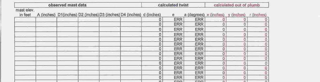
17 This procedure allows one or two people to evaluate the site in a relatively short time. Figure 11 is a data sheet prepared during a survey and Figure 12 shows one of the photographs, which has been highlighted to show a problem area. Figure 12. This methodology was designed not only to catch existing problems but also to locate potential future problems such as trees that may become a problem in a few years. 17
TOWER INSPECTION REPORT
 3010 S. Hwy 77, Suite 600 Waxahachie, Texas 75165 http://ctctower.com Office: 972/923-9504 Fax: 972/923-9619 TOWER INSPECTION REPORT PREPARED FOR MR. CUSTOMER 1,563 GUYED TOWER NEAR CITY, STATE JANUARY
TOWER INSTALLATION MANUAL For A.R.E. Guyed Pipe Towers Short Towers 43, 64 and 85 feet tall
 TOWER INSTALLATION MANUAL For A.R.E. Guyed Pipe Towers Short Towers 43, 64 and 85 feet tall Contents 1) Introduction...2 2) Site Selection and Preparation...2 3) Tools List...3 4) Parts List...4 5) Tower
Low Wind High Yields Series
 Low Wind High Yields Series Wind Turbines USER S MANUAL Introduction Low Wind High Yields Series rotor blades apply the latest advanced thermoplastic engineering and are manufactured by precision injection
Figure 1 - Parts Identification. Copyright 2002, DB Industries, Inc.
 User Instruction Manual Zorbit Energy Absorber Kits for Horizontal Lifeline Systems This manual is provided as the Maunfacturer s Instructions, and should be used as part of an employee training program
Installation, Operating, Inspection and Maintenance Instructions Ladder Climber s Safety System. Warning
 OWNER'S MANUAL Installation, Operating, Inspection and Maintenance Instructions Ladder Climber s Safety System Model # s: 6000, 6001, 6010 Warning You must read and fully understand all instructions, or
OWNER'S MANUAL. Turnbuckle. Stanchions. Warning
 GEMTOR, INC....when your life is on the line One Johnson Avenue Matawan, NJ 07747 732-583-6200 800-405-9048 Fax 732-290-9391 OWNER'S MANUAL Installation, Operating, Inspection and Maintenance Instructions
Tripod Setup Guide (M-TPx)
") Items needed: 1/2 inch wrench, mast level (M-MLA), medium size wire cutters, crescent wrench, all-purpose grease, tape measure, tie wraps, redi-mix cement (optional), shovel (optional), sledge hammer (for
Items needed: 1/2 inch wrench, mast level (M-MLA), medium size wire cutters, crescent wrench, all-purpose grease, tape measure, tie wraps, redi-mix cement (optional), shovel (optional), sledge hammer (for
Page 1 of 1 04/19/13 SBR
 Office of Roadway Engineering - Plan Insert Sheets Number Title Date Number Title Date Number Title Date 201015 Extension of Anchor Bolts 07/20/12 207000 Bikeway Pavement Marking Details 01/18/13 202010
ATOC Meteorological Tower (6 meter-4 level) Guide
 Guide") ATOC Meteorological Tower (6 meter-4 level) Guide SETUP Outline 1. Siting 2. Components 3. Transportation 4. The Tower 5. The Cables and Data Logger Siting Selecting an appropriate site for the weather
ATOC Meteorological Tower (6 meter-4 level) Guide SETUP Outline 1. Siting 2. Components 3. Transportation 4. The Tower 5. The Cables and Data Logger Siting Selecting an appropriate site for the weather
Safewaze FS983 Cable Safety Climb System Ladder Mount Instructions
 Safewaze FS983 Cable Safety Climb System Ladder Mount Instructions Ladder Mount Cable Safe Climb System B) Head Assembly with Cable A) Upright Mast C) Cable Standoff E) Cable Clamps D) Base Anchor Bracket
BEAMGUARD SAFETY POST TM INSTRUCTIONS
 BEAMGUARD SAFETY POST TM INSTRUCTIONS READ THESE WARNINGS BEFORE USING THE BEAMGUARD SAFETY POST! 1. Before use of this system, read and understand all instructions, warnings, cautions and notes marked
10m-130mm Tubular Tower. Technical Specifications
 10m-130mm Tubular Tower Technical Specifications ENALLAKTIKI ENERGIAKI 2006 Y 1 0 m / 1 0 m T U B U L A R T O W E R T E C H N I C A L S P E C S Index 1 Contact Details....3 2 Tubular Meteorological Towers....4
How to install AEA s 10 meter meteorological tower
 How to install AEA s 10 meter meteorological tower Before you start: This guide assumes that you have obtained permission from the land owner, consulted with US Fish & Wildlife Service and obtained approval
20', 15', AND 12' BALL STOPS ASSEMBLY INSTRUCTIONS
 20'-0" 15'-0" 1 739020 739020A 20' BALL STOP; STRAIGHT POLE 739015 739015A 15' BALL STOP; STRAIGHT POLE 739012 739012A 12' BALL STOP; STRAIGHT POLE Read all of the instructions before beginning. Make sure
User Instructions 1789 Parapet Wall Anchor
 User Instructions 1789 Parapet Wall Anchor This manual is intended to meet the Manufacturer Instructions as required by ANSI Z359.1 and should be used as part of an employee training program as required
Soma Wind Generators
 Soma Wind Generators 13M WINH TOWER INSTALLATION MANUAL ERTIFIED to AS4100 Steel Structures ode AS3995 (1994) Design of Steel Lattice Towers and Masts AS1170.2 (1989) SAA Wind Loading Manufactured by SOMA
BC Shackle. Made in the China. Alloy Steel Anchor Shackle. Instructions for handling and use - Please read in full before using this device
 BC Shackle Made in the China Alloy Steel Anchor Shackle Instructions for handling and use - Please read in full before using this device Index 1.) Introduction 2.) Warnings / General Use Guidelines 3.)
DIRECT AND INVERTED PENDULUMS. Model DP & RP. Roctest Limited, All rights reserved.
 INSTRUCTION MANUAL DIRECT AND INVERTED PENDULUMS Model DP & RP Roctest Limited, 2006. All rights reserved. This product should be installed and operated only by qualified personnel. Its misuse is potentially
Related Elevator Products
 37 SECTION 2 - Elevator Products Reeving Splices Related Elevator Products Reeving Splice Specifications PIN # Wire Rope Size Units per Carton Wt. per Carton (Lbs) Length (IN) Color Code 1119100012 3/8
User Manual 1792 Standing Seam Metal Roof Retractable Swivel Anchor
 1 User Manual 1792 Standing Seam Metal Roof Retractable Swivel Anchor This manual is intended to meet the Manufacturer Instructions as required by ANSI Z359.1 and should be used as part of an employee
Foundation Products. Poured In Ground Anchor Bolts E1 - E4. Structural Foundations E5 - E12. Copyright 2016 s Industry Inc. SIE-RA-CMP EN
 Foundation Products Poured In Ground Anchor Bolts E1 - E4 Structural Foundations E5 - E12 EA EB Poured in Ground Anchor Bolts Layout SIEMENS Anchor Bolts 131702-4X shown for reference purposes only! Actual
QUALITY ALUMINUM BOAT LIFTS, INC. INSTRUCTIONS. Dominator Lake Lift
 INSTRUCTIONS Dominator Lake Lift PHONE:251-986-3882 * FAX:251-986-3136 QABLDOMINATORINST.2014 P a g e 1 Quality Aluminum Boat Lifts, INC. Installation Instructions: Dominator Lake Lift Thank you for your
PUNE TECHTROL PVT LTD. Instruction and Maintenance Manual for Float and Tape Gauge FTG
 PUNE TECHTROL PVT LTD Instruction and Maintenance Manual for and Tape Gauge FTG INSTALLATION, OPERATION AND MAINTENANCE MANUAL FOR FLOAT AND TAPE GAUGE FTG 1 Introduction : It is used to measure and indicate
REPLACING THE AFT RUDDER CABLES
 REPLACING THE AFT RUDDER CABLES Note: You must have the assistance of a qualified Aircraft Mechanic to perform this procedure. A logbook entry with the mechanics signature is required. Please read these
Figure 1 - Parts Identification
 Instructions for the following series products: Zorbit Energy Absorber Kits (See back page for specific model numbers.) User Instruction Manual Zorbit Energy Absorber Kits for Horizontal Lifeline Systems
Safety Equipment Manufacturer Committee Consensus Document
 Safety Equipment Manufacturer Committee Consensus Document A. Scope and Application This manufacturer consensus document is intended to address use of a wire rope safety climb/system in the telecommunications
GEMTOR. ... when your life is on the line OWNER'S MANUAL. FLW Series Self-Retracting Lanyard/Fall Limiter
 GEMTOR TM... when your life is on the line OWNER'S MANUAL FLW Series Self-Retracting Lanyard/Fall Limiter Installation, Operating, Inspection and Maintenance Instructions Warning You must read and fully
WARNING! DO NOT THROW AWAY THESE INSTRUCTIONS! READ AND UNDERSTAND BEFORE USING EQUIPMENT!
 Guardian Fall Protection Kent, WA 800-466-6385 www.guardianfall.com GENERAL SYSTEM SELECTION CRITERIA: Selection of fall protection shall be made by a Competent Person. All fall protection equipment shall
M S I C R A N E S C A L E
 2 M E A S U R E M E N T S Y S T E M S I N T E R N A T I O N A L Table of Contents Forward...3 Safe Operating Guidelines...4 Operating Suggestions...4 Handling Hoist Motion...4 Safe Loading and Rigging
GM-121: Container End Lock Anchor Wand Page 1 WINSAFE CORP. GM 121 CONTAINER END LOCK ANCHOR WAND OPERATING INSTRUCTIONS AND MAINTENANCE
 GM-121: Container End Lock Anchor Wand Page 1 WINSAFE CORP. GM 121 CONTAINER END LOCK ANCHOR WAND OPERATING INSTRUCTIONS AND MAINTENANCE US Patent No. 6834745 This equipment conforms to 0321 EN795:1996
Installation and Training Manual
 AirForce1 Tower Kit Installation and Training Manual FuturEnergy Limited Ettington Park Business Centre Stratford upon Avon CV37 8BT +44 (0)1789 451070 Table of Contents Safety Notes... 3 Parts Supplied
DQM Annual Hopper QA Checks
 DQM Annual Hopper QA Checks The following document is intended to be a guide for conducting annual Dredge Quality Management quality assurance checks on hopper dredges. The procedures should provide general
ZL90-90 includes all all parts && hardware for easy assembly. Installation Instructions. With Patented FingerSafe Trolley System. ziplinefun.
 With Patented FingerSafe Trolley System ZL90-90 includes all all parts && hardware for easy assembly ziplinefun.com Ages 8+ weighing up up to to 250lbs Made in in the USA for for over over 35 35 years.
The Criticality of Cooling
 Reliability Solutions White Paper January 2016 The Criticality of Cooling Utilities, power plants, and manufacturing facilities all make use of cooling towers for critical heat transfer needs. By cycling
1.2 LIMITATIONS: Consider the following application limitations before using this equipment:
 User Instruction Manual Standing Seam Roof Anchor This manual is intended to meet the Manufacturer s Instructions, and should be used as part of an employee training program as required by OSHA. Figure
IMPORTANT: If you have questions on the use, care, or suitability of this equipment for your application, contact DBI/SALA.
 User Instruction Manual Precast Concrete Beam Horizontal Lifeline System This manual is provided as the Manufacturer s Instructions, and should be used as part of an employee training program as required
TEMPLE UNIVERSITY ENVIRONMENTAL HEALTH AND RADIATION SAFETY
 Page 1 of 9 ISSUED: 5/00 REVISED: 08/06 Introduction Purpose: In accordance with applicable regulations and Temple University, this policy was developed to minimize exposure to Ethylene Oxide. Applicability
Surveying & Measurement. Distance Measurement
 Surveying & Measurement Distance Measurement Introduction One of the most fundamental surveying operations is the measurement of horizontal distance between two points on the surface of the earth. There
CHAPTER 8 STAKING SIGNALS AND LIGHTING FIELD GUIDE. 8.1 Staking Traffic Control Signal Systems
 CHAPTER 8 STAKING STAKING Correct staking of traffic control signal or lighting systems is critical to the appropriate placement of system components. 8.1 Traffic Control Signal Systems Locating the components
STAKING TRAFFIC CONTROL SIGNAL SYSTEMS
 Locating the components of a traffic control signal is not an exact science; many factors influence the location of the components. These factors include: lane widths, radii, pedestrian curb ramp requirements,
ATTACHMENT O WIPP MINE VENTILATION RATE MONITORING PLAN
 ATTACHMENT O WIPP MINE VENTILATION RATE MONITORING PLAN (This page intentionally blank) ATTACHMENT O WIPP MINE VENTILATION RATE MONITORING PLAN TABLE OF CONTENTS O- Definitions... O- Objective... O- Design
BALL STOP INSTALLTION GUIDE
 BALL STOP INSTALLTION GUIDE GROUND SLEEVE INSTALLATION: 1. Locate the exact location of the ground sleeve. NOTE: Maximum recommended pole spacing is 20 feet on center. 2. Excavate the pole footing; refer
DESIGN CRITERIA DIVISION 4900 TRAFFIC SIGNALS
 DESIGN CRITERIA DIVISION 4900 TRAFFIC SIGNALS 4901 GENERAL: These criteria shall be adhered to for the design of all publiclyfinanced or privately-financed traffic signal systems to be installed in the
ADA Operations Contact Info
 Intro ADA Operations Contact Info Todd Grugel ph: 651-366-3531 email: todd.grugel@state.mn.us Joe Zilka ph: 651-366-3311 email: joseph.zilka@state.mn.us Harvey Unruh ph: 651-216-2912 email: harvey.unruh@state.mn.us
WARNING! DO NOT THROW AWAY THESE INSTRUCTIONS! READ AND UNDERSTAND BEFORE USING EQUIPMENT!
 Guardian Fall Protection Kent, WA 800-466-6385 www.guardianfall.com GENERAL SYSTEM SELECTION CRITERIA: Selection of fall protection shall be made by a Competent Person. All fall protection equipment shall
BRAKE WINCH RUP 503-[T/BT] EQUIPMENT FOR LIFTING LOADS. AT 053-[T/BT] xx
![BRAKE WINCH RUP 503-[T/BT] EQUIPMENT FOR LIFTING LOADS. AT 053-[T/BT] xx](/thumbs/88/115945274.jpg "BRAKE WINCH RUP 503-[T/BT] EQUIPMENT FOR LIFTING LOADS. AT 053-[T/BT] xx") Reference number: BRAKE WINCH RUP 503-[T/BT] EQUIPMENT FOR LIFTING LOADS DESIGNATED USE The brake winch RUP 503-[...]T series is a load lifting / lowering device. Device is equipped with safety brake for
Reference number: BRAKE WINCH RUP 503-[T/BT] EQUIPMENT FOR LIFTING LOADS DESIGNATED USE The brake winch RUP 503-[...]T series is a load lifting / lowering device. Device is equipped with safety brake for
CADET COMMAND HEADQUARTERS RAPPEL SITE INSPECTION CHECKLIST DATE OF TOWER CONSTRUCTION BUILT BY OWNED BY LAST DATE OF ANY MAJOR MODIFICATIONS
 CADET COMMAND HEADQUARTERS RAPPEL SITE INSPECTION CHECKLIST NAME AND LOCATION OF TOWER DATE OF TOWER CONSTRUCTION BUILT BY OWNED BY LAST DATE OF ANY MAJOR MODIFICATIONS (If applicable, list modification,
USER S INSTRUCTION MANUAL FOR THE INSTALLATION, OPERATION & MAINTENANCE OF THE GUARDIAN TEMPORARY HORIZONTAL LIFELINE SYSTEM
 USER S INSTRUCTION MANUAL FOR THE INSTALLATION, OPERATION & MAINTENANCE OF THE GUARDIAN 04630 TEMPORARY HORIZONTAL LIFELINE SYSTEM 1 WARNING This is a design compatible component for a comprehensive Guardian
John Paul (JP) Jones President
 Jones President") John Paul (JP) Jones President of Required Training for Telecommunications Tower Workers in the USA WHAT STANDARDS AND REGULATIONS DO WE TRAIN TO? OSHA CFR 29-1926 & 1910 ANSI 490.1 ANSI Z359 ANSI 10.48
John Paul (JP) Jones President of Required Training for Telecommunications Tower Workers in the USA WHAT STANDARDS AND REGULATIONS DO WE TRAIN TO? OSHA CFR 29-1926 & 1910 ANSI 490.1 ANSI Z359 ANSI 10.48
SERIES 500 VARIABLE RANGE PNEUMATIC DIFFERENTIAL PRESSURE TRANSMITTER
 Man500e 09/2006 Installation Operation and Maintenance Instructions SERIES 500 VARIABLE RANGE PNEUMATIC DIFFERENTIAL PRESSURE TRANSMITTER INDEX 1. INSTALLATION 2. COMPRESSED AIR SUPPLY 3. FLOW MEASURE
IS37 10 Metre Instrument Mast Handbook
 IS37 10 Metre Instrument Mast Handbook Version 10.1 6 th February 2014 Environdata Australia Pty Ltd 42-44 Percy Street Warwick Queensland 4370 Australia Phone: (07) 4661 4699 Fax: (07) 4661 2485 International
FALL PROTECTION (SAF-SPI-06)
") 1. PURPOSE To describe the Ontario Operations standard methods for preventing serious injury resulting from fall from heights and to provide a Standard for Fall Protection to safeguard employees who work
1. PURPOSE To describe the Ontario Operations standard methods for preventing serious injury resulting from fall from heights and to provide a Standard for Fall Protection to safeguard employees who work
BUTTERFLY VALVES Series 800
 BUTTERFLY VALVES Series 800 WARNING Before proceeding read ALL instructions and become familiar with the equipment and associated drawings. Follow ALL applicable safety regulations and codes for pressurized
OPERATION AND INSTRUCTION MANUAL Flat Roof Anchor Model: FRA250L-10X-CTS
 OPERATION AND INSTRUCTION MANUAL Flat Roof Anchor Model: FRA250L-10X-CTS (Patent Pending) WARNING: ALL PERSONS USING THIS EQUIPMENT MUST READ AND UNDERSTAND ALL INSTRUCTIONS. FAILURE TO DO SO MAY RESULT
Buckingham Mfg. Co., Inc. OX BLOCK TM Instructions and Warnings
 OVERVIEW The Buckingham OX BLOCK is a rope snatch block with an integrated friction bar used for lowering loads, snubbing loads, and raising loads. It allows the rigging professional to handle loads with
STRAIGHT POLE TENSIONED BATTING TUNNEL POLE LAYOUT
 STRAIGHT POLE TENSIONED BATTING TUNNEL POLE LAYOUT SOFTBALL: 55' x 14' Nets BASEBALL: 75' x 14' Nets No. 330155 No. 330175 63'-0" 83'-0" SINGLE NET 1 1 No. 330255 No. 330275 63'-0" 83'-0" DOUBLE NET No.
Figure 1 - Cable Grip Horizontal Lifeline Termination ZORBIT ENERGY ABSORBER RELEASE TAB
 Instructions for the following series products: Cable Grip (See back pages for specific model numbers.) User Instruction Manual Cable Grip Kit for Horizontal Lifeline Systems This manual is provided as
OMG Southeast & Southwest RIGGING SAFETY PROGRAM (29 CFR Part , , , , , & ANSI B30.5, ANSI B30.
 OMG Southeast & Southwest RIGGING SAFETY PROGRAM (29 CFR Part 1926.251, 1926.550, 1910.180, 1910.184, 1910.330, & ANSI B30.5, ANSI B30.8) Nearly every project is required to perform some type of rigging
MUELLER. A Wall Type. Indicator Post. Reliable Connections. General Information 2. Technical Data/ Dimensions 3. Installation 4-5.
 Installation Instructions manual MUELLER table of contents PAGE A-20814 Wall Type General Information 2 Technical Data/ Dimensions Installation 4-5 Maintenance 6 Parts 7 Indicator Post! WARNING: 1. Read
GM-120: Container Top Lock Anchor Wand Page 1 WINSAFE CORP. GM 120 CONTAINER TOP LOCK ANCHOR WAND OPERATING INSTRUCTIONS AND MAINTENANCE
 GM-120: Container Top Lock Anchor Wand Page 1 WINSAFE CORP. GM 120 CONTAINER TOP LOCK ANCHOR WAND OPERATING INSTRUCTIONS AND MAINTENANCE US Patent No. 6834745 This equipment conforms to 0321 EN795:1996
User Instruction Manual For Davit Rescue System
 Instructions for the following series products: Rescue Davit System Model numbers 8004000 and 8302500 User Instruction Manual For Davit Rescue System This manual should be used as part of an employee training
WHISPER 42 FOOT (13 Meter) TOWER KIT for SKYSTREAM 3.7 AND WHISPER 500 WIND TURBINE
 TOWER KIT for SKYSTREAM 3.7 AND WHISPER 500 WIND TURBINE") WHISPER 42 FOOT (13 Meter) TOWER KIT for SKYSTREAM 3.7 AND WHISPER 500 WIND TURBINE Made in the USA by: SOUTHWEST WINDPOWER, INC. 1801 Route 66 Flagstaff, AZ 86001 (928) 779-9463 SOUTHWEST WINDPOWER Page
WHISPER 42 FOOT (13 Meter) TOWER KIT for SKYSTREAM 3.7 AND WHISPER 500 WIND TURBINE Made in the USA by: SOUTHWEST WINDPOWER, INC. 1801 Route 66 Flagstaff, AZ 86001 (928) 779-9463 SOUTHWEST WINDPOWER Page
Page 1. Single Scull Car Rack Assembly and User s Manual " "
 Page 1 Single Scull Car Rack Assembly and User s Manual Page 2 Items in the box: (2) V cradles (2) 4 rails (1) 1 3/4 X 18 rail coupler (4) 1/4-20 X 4 1/2 bolts (2) 1/4-20 X 2 1/2 bolts (12) 1/4 flat washers
A A A T E C H N O L O G Y
 A A A T E C H N O L O G Y & SPECIALTIES CO., INC. C O N S T A N T E F F O R T S U P P O R T S TOTAL SOLUTION SERVICE For the Industrial Piping Marketplace 2012 www.aaatech.com 4 1 Y E A R S S E R V I N
INSTALLATION INSTRUCTIONS FOR EXHAUST CUFF MODIFICATION
 INSTALLATION INSTRUCTIONS FOR EXHAUST CUFF MODIFICATION Document # PCA1001-22 Revision LTR: A Date: 07/06/09 1 Notes: 1. The cuff must be installed onto the aircraft prior to painting. Once installed the
Precision Liquid Settlement Array Manual
 Precision Liquid Settlement Array Manual All efforts have been made to ensure the accuracy and completeness of the information contained in this document. RST Instruments Ltd reserves the right to change
Safe Work Practices (SWP) SWP (6) FALL PROTECTION PROGRAM
 SWP (6) FALL PROTECTION PROGRAM") SWP (6) FALL PROTECTION PROGRAM The following information on Fall Protection has been based around the BC OHS Regulations, standards, policies and guidelines. Prior to starting work outside of BC, the
SWP (6) FALL PROTECTION PROGRAM The following information on Fall Protection has been based around the BC OHS Regulations, standards, policies and guidelines. Prior to starting work outside of BC, the
USE AND MAINTENANCE LIGHT TOWER
 USE AND MAINTENANCE LIGHT TOWER General Safety Information Allowed use The light tower has been designed to lighten the area in which it is positioned and oriented, after installing it on a generating
Guyed 70 Foot Tower Kit for Skystream 3.7 Owner s Manual
 Guyed 70 Foot Tower Kit for Skystream 3.7 Owner s Manual 3-CMLT-1028-03 REV F Installation Operation 2013 XZERES Corp All Rights Reserved Please read this manual thoroughly before beginning assembly. If
MATERIAL HANDLING - FIELD RIGGING SAFETY PROGRAM
 Title: Material Handling - Rigging Effective Date: 12/4/2014 Control Number: THG_0049 Revision Number: 1 Date: 10/23/2015 Annual Review Completed: 5/13/2015 MATERIAL HANDLING - FIELD RIGGING SAFETY PROGRAM
Wind Resource Assessment for FALSE PASS, ALASKA Site # 2399 Date last modified: 7/20/2005 Prepared by: Mia Devine
 813 W. Northern Lights Blvd. Anchorage, AK 99503 Phone: 907-269-3000 Fax: 907-269-3044 www.aidea.org/wind.htm Wind Resource Assessment for FALSE PASS, ALASKA Site # 2399 Date last modified: 7/20/2005 Prepared
Zip-Line Kit Instructions
 1 Zip-Lines Ireland - Zip-Line Kit Instructions DC001A Zip-Line Kit Instructions Thank you for your purchase of the ZLI Zip-line kit! This product was engineered to provide safe fun for all ages when the
UNDERWATER BRIDGE INSPECTION REPORT DISTRICT 4 - OTTER TAIL COUNTY
 UNDERWATER BRIDGE INSPECTION REPORT STRUCTURE NO. L0885 TWP NO. 970 OVER THE OTTER TAIL RIVER DISTRICT 4 - OTTER TAIL COUNTY PREPARED FOR THE MINNESOTA DEPARTMENT OF TRANSPORTATION BY COLLINS ENGINEERS,
MUELLER A A Non-Adjustable. Vertical Indicator Posts. Reliable Connections. General Information 2. Technical Data 3.
 Installation Instructions manual MUELLER table of contents PAGE A-20808 General Information 2 Technical Data 3 Dimensions 4 A-20809 Non-Adjustable Installation 5-6 Parts 7 Maintenance 8 Vertical Indicator
FLANGED TWO-PIECE BALL VALVES
 INTRODUCTION This instruction manual includes installation, operation, and maintenance information for FNW flanged split-body ball valves. This manual addresses lever operated ball valves only. Please
LIFTING MAGNETS ERIEZ MAGNETICS
 MJ-2300E Installation, Operation and Maintenance Instructions LIFTING MAGNETS ERIEZ MAGNETICS HEADQUARTERS: 2200 ASBURY ROAD, P.O. BOX 10608, ERIE, PA 16514 0608 U.S.A. WORLD AUTHORITY IN ADVANCED TECHNOLOGY
Side-of-Pole Mount for 1 Module (SPM1) For Module Types A & B
 For Module Types A & B") Side-of-Pole Mount for 1 Module (SPM1) For Module Types A & B ASSEMBLY INSTRUCTIONS step-by-step assembly and installation Version 1, Rev A PCN 080311-2 SP3363-1 Side-of-Pole Mount for 1 Module (SPM1)
Side-of-Pole Mount for 1 Module (SPM1) For Module Types A & B ASSEMBLY INSTRUCTIONS step-by-step assembly and installation Version 1, Rev A PCN 080311-2 SP3363-1 Side-of-Pole Mount for 1 Module (SPM1)
Surface exploration drilling
 Checklist Surface exploration drilling This checklist is intended to assist employers to identify common hazards and manage risks associated with surface exploration drilling. June 2017 Background In surface
The purpose of this training is to give field technicians awareness training and guidelines on potential hazards they may encounter in the field.
 Purpose The purpose of this training is to give field technicians awareness training and guidelines on potential hazards they may encounter in the field. Fall Protection and Prevention JELD-WEN Field Employees
"RIGGING SAFETY IN CONSTRUCTION ENVIRONMENTS"
 PRESENTER'S GUIDE "RIGGING SAFETY IN CONSTRUCTION ENVIRONMENTS" Part of the "CONSTRUCTION SAFETY KIT" Series Quality Safety and Health Products, for Today...and Tomorrow OUTLINE OF MAJOR PROGRAM POINTS
Buckingham Mfg. Co., Inc. OX BLOCK TM Instructions and Warnings
 OVERVIEW The Buckingham OX BLOCK is a rope snatch block with an integrated friction bar used for lowering loads, snubbing loads, and raising loads. It allows the rigging professional to handle loads with
Model: 5100 OmniSteel Volleyball System
 Model: 5100 OmniSteel Volleyball System Installation, Operation and Maintenance Instructions Please read all instructions before attempting installation or operation of these units SAVE THESE INSTRUCTIONS
Operator's Manual Supplement
 Operator's Manual Supplement Traveling Fall Arrest Anchor System Original Instructions First Edition Fifth Printing Part No. 1256390GT Operator's Manual Supplement Genie Self-propelled Boom Products and
Installation Drawings & Instructions Fall Protection Systems
 ISO 9001 Registered Installation Drawings & Instructions Fall Protection Systems Attach the Cougar Slider only at this Sternum Connection Point CSA Z259.2.1-98 & ANSI Z359.1-M1992 [Canada & USA] Revision
Title: Standard Operating Procedure for Elemental and Organic Carbon (EC and OC) using Non-Dispersive Infrared Detection (NDIR)
 using Non-Dispersive Infrared Detection (NDIR)") Procedure No: SOP-025 Revision No: 1.0 (January 21, 2011) Page No.: 1 of 8 1. INTRODUCTION AND SCOPE To obtain timely data for the purpose of air quality assessment, air quality trend reporting and to
Procedure No: SOP-025 Revision No: 1.0 (January 21, 2011) Page No.: 1 of 8 1. INTRODUCTION AND SCOPE To obtain timely data for the purpose of air quality assessment, air quality trend reporting and to
Access Management Standards
 Access Management Standards Section 1: Application of Access Standards This chapter describes the Department's access management standards for access connections on the county roadway system. The standards
Reliance Industries, LLC Operating instructions for the / Bolt-on D-Ring Anchorage. Model # 3071
 Reliance Industries, LLC Operating instructions for the 3071-1 / 3071-2 Bolt-on D-Ring Anchorage Model # 3071 Reliance Industries, LLC PO Box 140008 Denver, CO 80214 Ph. (800) 488-5751 Ph. (303) 424-8650
1.3 LIMITATIONS: The following application limitations must be recognized and considered before using this product:
 3965 Pepin Avenue Red Wing, MN 55066-1837 Toll Free: (800) 328-6146 Phone: (651) 388-8282 Fax: (651) 388-5065 www.protecta.com User Instruction Manual AJ720A Concrete Anchor This manual is intended to
ELECTRICAL (COMPREHENSIVE) SAFETY PROGRAM REGULATORY STANDARD: OSHA - 29 CFR CFR , ,
 SAFETY PROGRAM REGULATORY STANDARD: OSHA - 29 CFR CFR , ,") ELECTRICAL (COMPREHENSIVE) SAFETY PROGRAM REGULATORY STANDARD: OSHA - 29 CFR 1910.331 335-29 CFR 1926.302, 1926.416, 1926.417 BASIS: The National Safety Council estimates that there are at least 300 deaths
ELECTRICAL (COMPREHENSIVE) SAFETY PROGRAM REGULATORY STANDARD: OSHA - 29 CFR 1910.331 335-29 CFR 1926.302, 1926.416, 1926.417 BASIS: The National Safety Council estimates that there are at least 300 deaths
SAFE WALKS PROGRAM FREQUENTLY ASKED QUESTIONS
 SAFE WALKS PROGRAM FREQUENTLY ASKED QUESTIONS Why does the City have a Safe Walks Program? The Safe Walks program was initiated in 2006 at the request of City Council in order to address the increasing
3/8" Safety Cable Systems
 3/8" Safety Cable Systems Ladder-Mount 3/8" Cable System (No Slider) Kits include appropriate length of aircraft cable, top and bottom support brackets, 12" tensioning turnbuckle, tension spring, and all
CRYOGENIC TANK SERVICES - CHART RECORDER MANUAL
 CRYOGENIC TANK SERVICES - CHART RECORDER MANUAL Pressure Chart Recorder / Temperature Chart Recorder / Dual Recorder Portable Mechanical Chart Recorder for the accurate measurement and recording of Pressure
TRI-POD SETUP. Guidelines for Typical Field Setup. Site Selection
 TRI-POD SETUP Guidelines for Typical Field Setup Site Selection Use the following guidelines to help you choose an appropriate site for setting up the Station and protecting against field hazards. When
TV-114 TV-114-A Wind Speed Sensor User s Manual
 Relied on Worldwide in the Most Extreme Conditions TV-114 TV-114-A Wind Speed Sensor User s Manual Texas Electronics, Inc. Dallas, TX 75237 Fax.214.631.4218 4230 Shilling Way Tel.214-631-2490 www.texaselectronics.com
TD-106-5D TD-106-5D-A Wind Direction Sensor User s Manual
 Relied on Worldwide in the Most Extreme Conditions TD-106-5D TD-106-5D-A Wind Direction Sensor User s Manual Texas Electronics, Inc. Dallas, TX 75237 Fax.214.631.4218 4230 Shilling Way Tel.214-631-2490
WIND DATA REPORT. Paxton, MA
 WIND DATA REPORT Paxton, MA July 1, 2011 September 30, 2011 Prepared for Massachusetts Clean Energy Center 55 Summer Street, 9th Floor Boston, MA 02110 by Eric Morgan James F. Manwell Anthony F. Ellis
Managing Mobile Crane Hazards. Paul Satti Construction Safety Council. Hazards of Working Around Cranes. Key Concepts:
 Managing Mobile Crane Hazards Paul Satti Construction Safety Council Hazards of Working Around Cranes Key Concepts: Electrocution Hazards Caught-In, Compressed or Crushing Hazards Struck-By Hazards Other
PENCOFLEX COUPLING ASSEMBLY AND MAINTENANCE
 ATEX 1-ASSEMBLY - During the final boring of couplings supplied with a pre-bore, make sure that the plate to be machined is centered correctly on its larger diameter. In this way, the bore will be absolutely
Moai Bike Rack Heavy Duty Submittal Sheet. Materials: 2.0 Schedule 40 Pipe (2.375 OD) Finishes: Capacity: Mount Options: Setbacks: 2 Bikes
 Finishes: Capacity: Mount Options: Setbacks: 2 Bikes") Submittal Sheet Materials: 2.0 Schedule 40 Pipe (2.375 OD) Finishes: Galvanized An after fabrication hot dipped galvanized finish is available. Powder Coat Our powder coat finish assures a high level of
Submittal Sheet Materials: 2.0 Schedule 40 Pipe (2.375 OD) Finishes: Galvanized An after fabrication hot dipped galvanized finish is available. Powder Coat Our powder coat finish assures a high level of
TO RECEIVE the most benefit from a
 Using Surveying Equipment TO RECEIVE the most benefit from a tool, it must be used properly. In addition, it must be well maintained. In most cases, the user will need some instruction and training regarding