500 Series Operations Manual _A
|
|
|
- Jasmin Nichols
- 5 years ago
- Views:
Transcription

1 500 Series Operations Manual _A
2 Thank You! Thank you for choosing Humminbird, America's #1 name in fishfinders. Humminbird has built its reputation by designing and manufacturing topquality, thoroughly reliable marine equipment. Your Humminbird is designed for trouble-free use in even the harshest marine environment. In the unlikely event that your Humminbird does require repairs, we offer an exclusive Service Policy - free of charge during the first year after purchase, and available at a reasonable rate after the one-year period. For complete details, see the separate warranty card included with your unit. We encourage you to read this operations manual carefully in order to get full benefit from all the features and applications of your Humminbird product. Contact our Customer Resource Center at either or visit our website at WARNING! This device should not be used as a navigational aid to prevent collision, grounding, boat damage, or personal injury. When the boat is moving, water depth may change too quickly to allow time for you to react. Always operate the boat at very slow speeds if you suspect shallow water or submerged objects. WARNING! Disassembly and repair of this electronic unit should only be performed by authorized service personnel. Any modification of the serial number or attempt to repair the original equipment or accessories by unauthorized individuals will void the warranty. Handling and/or opening this unit may result in exposure to lead, in the form of solder. WARNING! This product contains lead, a chemical known to the state of California to cause cancer, birth defects and other reproductive harm. NOTE: Not all features discussed in this manual are available on all models. Every effort has been made to identify those features that are unique to specific models only, and to identify which models support those features. Please read the manual carefully in order to understand the full capabilities of your model. Humminbird, DualBeam PLUS, SmartCast, Selective Fish ID+, WhiteLine, QuadraBeam PLUS, RTS, X-Press Menu, Fish ID+, WideSide, Structure ID, TrueArch, UltraBlack, Angler Profile Presets, and WeatherSense are trademarked by or registered trademarks of Humminbird Humminbird, Eufaula AL, USA. All rights reserved. i
3 Table of Contents How Sonar Works 1 Single Beam Sonar Dualbeam Sonar (565 Fishfinders only) QuadraBeam PLUS Sonar (575 Fishfinders only) What s On the Display 5 Views 7 Sonar View 8 Understanding Sonar History Real Time Sonar (RTS ) Window Bottom Presentation Sonar Zoom View /83 khz Split Sonar View (575 Fishfinders only) Big Digits View Side Beam View (575 Fishfinders only) Key Functions 19 POWER/LIGHT Key VIEW Key MENU Key WAY Cursor Control Key EXIT Key Powering Up the Unit 21 The Menu System 22 Start-Up Options Menu 24 Normal Operation Simulator System Status Self Test Accessory Test ii
4 Table of Contents Sonar X-Press Menu 28 Sensitivity Upper Range (Advanced; Sonar, Split Sonar, Big Digits Views only) Lower Range Chart Speed Bottom View Quad Layout (575 Fishfinders only, Side Beam View only) Zoom Level (Sonar Zoom View only) Sonar Menu Tab 35 Beam Select (575 Fishfinders only) Fish ID Fish ID Sensitivity Real Time Sonar (RTS ) Window Zoom Width khz Sensitivity (Advanced; 575 Fishfinders only) khz Balance (Advanced; 575 Fishfinders only) Depth Lines (Advanced) Surface Clutter (Advanced) Noise Filter (Advanced) Max Depth (Advanced) Water Type (Advanced) Alarms Menu Tab 45 Depth Alarm Fish ID Alarm Low Battery Alarm Temp Alarm Alarm Tone Setup Menu Tab 49 Units - Depth Units - Temp (International only) Units - Distance (with Temp/Speed only) Units - Speed (with Temp/Speed only) User Mode iii
5 Table of Contents Language (International only) Triplog Reset (with Temp/Speed only) Restore Defaults Select Views (Advanced) Select Readouts (Advanced; Sonar View only) Depth Offset (Advanced) Temp Offset (Advanced) Speed Calibration (Advanced; with Temp/Speed only) Troubleshooting Series Doesn t Power Up Series Defaults to Simulator with a Transducer Attached Display Problems Finding the Cause of Noise Series Fishfinder Accessories 60 Specifications 61 Glossary 63 Contact Humminbird 81 NOTE: Entries in this Table of Contents which list (International only) are only available on products sold outside of the US by our authorized International Distributors. To obtain a list of authorized International Distributors, please visit our website at or contact our Customer Resource Center at to locate the distributor nearest you. NOTE: Entries in this Table of Contents which list (with Temp/Speed only) require the purchase of a separate accessory. You can visit our website at to order these accessories online or contact our Customer Resource Center at iv

6 How Sonar Works Sonar technology is based on sound waves. The 500 Series Fishfinder uses sonar to locate and define structure, bottom contour and composition, as well as depth directly below the transducer. Your 500 Series Fishfinder sends a sound wave signal and determines distance by measuring the time between the transmission of the sound wave and when the sound wave is reflected off of an object; it then uses the reflected signal to interpret location, size, and composition of an object. Sonar is very fast. A sound wave can travel from the surface to a depth of 240 ft (70 m) and back again in less than 1/4 of a second. It is unlikely that your boat can "outrun" this sonar signal. SONAR is an acronym for SOund and NAvigation Ranging. Sonar utilizes precision sound pulses or "pings" which are emitted into the water in a teardrop-shaped beam. The sound pulses "echo" back from objects in the water such as the bottom, fish and other submerged objects. The returned echoes are displayed on the LCD screen. Each time a new echo is received, the old echoes are moved across the LCD, creating a scrolling effect. 1

 are commonly used on consumer sonar and provide a good balance between depth performance and resolution.")
 measures power output over the entire transmit cycle.")
7 When all the echoes are viewed side by side, an easy to interpret "graph" of the bottom, fish and structure appears. The sound pulses are transmitted at various frequencies depending on the application. Very high frequencies (455 khz) are used for greatest definition but the operating depth is limited. High frequencies (200 khz) are commonly used on consumer sonar and provide a good balance between depth performance and resolution. Low frequencies (83 khz) are typically used to achieve greater depth capability. The power output is the amount of energy generated by the sonar transmitter. It is commonly measured using two methods: Root Mean Square (RMS) measures power output over the entire transmit cycle. Peak to Peak measures power output at the highest points. The benefits of increased power output are the ability to detect smaller targets at greater distances, ability to overcome noise, better high speed performance and enhanced depth capability. 2

8 Single Beam Sonar Your Humminbird 515, 525 or 535 Fishfinder uses a 200 khz single beam sonar system with a 20 area of coverage. Depth capability is affected by such factors as boat speed, wave action, bottom hardness, water conditions and transducer installation. DualBeam Sonar (565 Fishfinders only) Your Humminbird Fishfinder 565 uses a 200/83 khz Dual Beam sonar system with a wide (60 ) area of coverage. DualBeam sonar is optimized to show the greatest bottom definition using a narrow (20 ) beam yet can still indicate fish found in the wide (60 ) beam when the Fish ID+ feature is turned on. DualBeam is ideal for a wide range of conditions - from shallow to very deep water in both fresh and salt water. Depth capability is affected by such factors as boat speed, wave action, bottom hardness, water conditions and transducer installation. NOTE: It's important to note that your 565 Fishfinder is a DualBeam-only unit and should not be confused with the DualBeam PLUS functionality of the 575 Fishfinder. DualBeam will only show hollow fish symbols from the wide 83 khz beam when Fish ID+ is turned on. You cannot view the 83k Hz sonar information separately from the 200 khz sonar information as you can in a DualBeam Plus 575 Fishfinder unit. 3

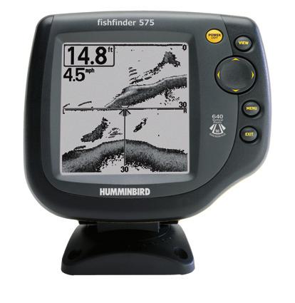
9 QuadraBeam PLUS Sonar (575 Fishfinders only) Your Humminbird 575 Fishfinder supports QuadraBeam PLUS sonar. QuadraBeam PLUS sonar provides an extremely wide 90 area of coverage. QuadraBeam PLUS starts with two fan-shaped khz Side Structure locating sonar beams to spot fish, bait and structure to the left and right of the boat over an area of the bottom that s always equal to twice your depth. QuadraBeam PLUS finds more fish faster, and can even tell you where to put your bait by showing if fish are to the left, right or directly beneath your boat. For structure directly below your boat, Quadrabeam PLUS uses a DualBeam PLUS 200/83 khz sonar system with a wide (60 ) area of coverage. DualBeam PLUS sonar has a narrowly focused 20 center beam, surrounded by a second beam of 60, expanding your coverage to an area equal to your depth. In 20 feet of water, the wider beam covers an area 20 feet wide. The 20 center beam is focused on the bottom, to show you structure, weeds and cover. The 60 wide beam is hunting for fish in the wide coverage area. DualBeam PLUS sonar returns can be blended together, viewed separately or compared side-by-side. DualBeam PLUS is ideal for a wide range of conditions - from shallow to very deep water in both fresh and salt water. Depth capability is affected by such factors as boat speed, wave action, bottom hardness, water conditions and transducer installation. 4

10 What s On the Display The 500 Series Fishfinder can display a variety of useful information about Depth - water depth; can be set to alarm when the water becomes too shallow. Speed - if a Temp/Speed accessory is attached, your Fishfinder can display the speed of the boat, and can keep a Triplog of nautical or statute miles traveled. Temperature - water surface temperature. Timer - elapsed time with Temp/Speed Accessory. Distance - distance traveled with Temp/Speed Accessory. Average Speed - average speed reading with Temp/Speed Accessory. Bait Ball Hard Bottom Rocky Bottom Second Sonar Return - when the sonar signal bounces between the bottom and the surface of the water and back again. Use the appearance of the second return to determine bottom hardness. Hard bottoms will show a strong second return, while soft bottoms will show a very weak one or none at all. NOTE: Entries in this view that list (with Temp/Speed) are available only if the optional-purchase 5

11 the area under and adjacent to your boat, including the following items: 83 khz, Wide Beam Hollow Fish Symbol (ONLY available on Dual Beam Units) Structure - where fish may be hiding. Fish - fish are displayed as arches and/or fish icons, and the unit can be set to alarm when a fish of a certain size is detected. When a target is detected and Fish ID+ TM is on, a Fish ID+ TM symbol with depth is displayed. The size of the symbol shows the intensity of the sonar return. The unit will clearly show schools of Bait Fish as "clouds" of different shapes and sizes, depending on the number of fish and boat speed. 200 khz, Narrow Beam Shaded Fish Symbol Thermoclines - layers of water with different temperatures that appear at different depths and different times of the year. A thermocline typically appears as a continuous band of many gray levels moving across the display at the same depth. Soft Bottom RTS (Real Time Sonar) Window Battery Voltage - the voltage of the boat s battery; can be set to alarm if the voltage falls below a certain point. device is connected to the Fishfinder. 6
.")
12 Views The views available on your Fishfinder are: Sonar views: Sonar View Zoom View 200/83 khz Split Sonar View (575 Fishfinder only) Big Digits View Side Beam View (575 Fishfinder only). NOTE: When you change any menu settings that affect the sonar, the view will update immediately (i.e. you don t have to exit the menu to apply the change to the screen). For instance, by switching between "Inverse" and "Structure ID " from the X-Press Menu it is possible to quickly alternate between the two viewing methods. Sonar View is the default view. When the VIEW key is pressed, the display cycles through the available views. When the EXIT key is pressed, the display cycles through the available views in reverse order. Any view can be hidden or displayed as part of the view rotation using the Views Menu tab. 7
13 Sonar View Sonar View presents a historical log of sonar returns. Depth is always displayed. Readouts for temperature and speed are automatically displayed if the appropriate accessory is connected. The most recent sonar returns are charted on the right side of the window; as new information is received, the older information is moved across the display to the left. A Digital Depth Readout is displayed in the upper left corner. A scale with Upper and Lower Depth Range readouts appears along the right edge of the Sonar View. The scale indicates the distance from the surface of the water to a depth range sufficient to show the bottom. Depth Range is automatically selected to keep the bottom visible on the display, although you can adjust it manually as well (see Sonar X-Press Menu). Six additional Digital Readouts display information from optional-purchase accessories. These information boxes can be customized to show only the information desired (see Setup Menu Tab, Select Readouts). Depth Sonar View Upper Depth Range Temperature Triplog RTS Window Sonar History Window Lower Depth Range NOTE: If the Depth number is flashing, it means that the unit is having trouble locating the bottom. This usually happens if the water is too deep, the transducer is out of the water, the boat is moving too fast, or for any other reason that the unit can t accurately receive continuous data. 8
14 Understanding Sonar History Real Time Sonar (RTS ) Window It is important to understand the significance of the display. The display does NOT show a literal 3-dimensional representation of what is under the water. Each vertical band of data received by the control head and plotted on the display represents something that was detected by a sonar return at a particular time. As both the boat and the targets (fish) may be moving, the returns are only showing a particular segment of time when objects were detected, not exactly where those objects are in relation to other objects shown on the display. A Real Time Sonar (RTS ) Window appears on the right side of the display in the Sonar View only. The RTS Window always updates at the fastest rate possible for depth conditions and shows only the returns from the bottom, structure and fish that are within the transducer beam. The RTS Window plots the depth and intensity of a sonar return (see Sonar Menu - RTS Window). The Narrow RTS Window indicates the sonar intensity through the use of grayscale. The grayscale used matches the bottom view grayscale setting used in the sonar history window (i.e. Inverse, Structure ID, WhiteLine, Bottom Black). The depth of the sonar return is indicated by the vertical placement of the return on the display depth scale. The Wide RTS Window indicates the sonar intensity through the use of a bar graph. The length of the plotted return provides an indication of whether the return is weak or strong. The depth of the sonar return is indicated by the vertical placement of the return on the display depth scale. The Wide RTS Window does not make use of grayscale. 9

15 Bottom Presentation As the boat moves, the unit charts the changes in depth on the display to create a profile of the Bottom Contour. The type of bottom can be determined from the return charted on the display. A Hard Bottom such as compacted sediment or flat rock appears as a thinner line across the display. A Soft Bottom such as mud or sand appears as a thicker line across the display. Rocky Bottoms have a broken, random appearance. Bottom Contour Profile with RTS Window. Temp/Speed Accessory is optional. Hard Bottom Rocky Bottom Soft Bottom The sonar returns from the bottom, structure and fish can be represented as either Inverse (default), WhiteLine, Structure ID, or Bottom Black. See Sonar X-Press Menu: Bottom View for details on how to set the bottom view. 10

16 Inverse is a method where weak returns are shown with dark pixels and strong returns with lighter pixels. This has the benefit of ensuring that weak signals will be clearly visible on the display. Structure ID represents weak returns as light pixels and strong returns as dark pixels. This has the benefit of ensuring that strong returns will be clearly visible on the display. 11


17 WhiteLine highlights the strongest sonar returns in white, resulting in a distinctive outline. This has the benefit of clearly defining the bottom on the display. Bottom Black displays all pixels below the bottom contour as black, regardless of signal strength. This has the benefit of providing a high contrast between the bottom and other sonar returns on the display. Any targets such as fish, structure and thermoclines will be shown using the Structure ID method. 12

18 Sonar Zoom View Sonar Zoom View increases the displayed resolution to separate sonar returns that are very close together, such as those caused by fish suspended close to the bottom or within structure. In Zoom View, the display is split to show a narrow slice of the full range view on the right and the zoomed view on the left. The full range view on the right also contains the Zoom Preview Box that shows what part of the full range view is shown in zoom view on the left; the Zoom Preview Box tracks the bottom in the full range view. As the depth changes, the zoomed view updates automatically to display a magnified image of the bottom. The Zoom Preview Box shows where the zoomed view is in relation to the full range view. The Zoom Level, or magnification, is displayed in the lower left corner and can be changed to suit conditions (see Sonar X-Press Menu: Zoom Level). Upper and Lower Zoom Depth Range numbers indicate the depth of the water which is being viewed. Digital depth is displayed in the upper left hand corner. The digital readouts in the Sonar Zoom View cannot be customized; therefore, information such as water temperature and voltage are unavailable in the Sonar Zoom View. Depth Zoomed View Zoom Level Sonar Zoom View Upper Depth Range, Full Range View Upper Depth Range, Zoom View Full Range View Zoom Preview Box Lower Depth Range, Zoom View Lower Depth Range, Full Range View 13

19 200/83 khz Split Sonar View (575 Fishfinders only) Split Sonar View displays sonar returns from the 83 khz wide beam on the left side of the screen and displays sonar returns from the 200 khz narrow beam on the right side of the screen and is only available on the 575 Fishfinder. Depth is always displayed in the upper left hand corner. You can use the Split Sonar View to make side by side comparisons between the sonar returns from the 83 khz wide beam and the 200 khz narrow beam. The digital readouts in the Split Sonar View cannot be customized; therefore, information such as water temperature and voltage are unavailable in the Split Sonar View. Depth 200/83 khz Split Sonar View Upper Depth Range 200 khz Sonar History Window 83 khz Sonar History Window Lower Depth Range 14

20 Big Digits View Big Digits View provides digital data in a large, easy-to-see format. Depth is always displayed. Readouts for temperature, speed and Triplog information are displayed automatically if the appropriate accessory is connected to the system. The Triplog shows distance traveled, average speed, and time elapsed since the Triplog was last reset. The digital readouts in the Big Digits View cannot be customized. Big Digits View Depth Temperature Speed Timer shows the time elapsed since Triplog was last reset. Distance is the distance traveled since the Triplog was last reset. Voltage displays the battery voltage. Average Speed shows the speed since the Triplog was last reset. 15

21 Side Beam View (575 Fishfinders only) Side Beam View shows sonar information from both the left and right 455 khz beams and the 200 khz down-looking beam in one view and is only available on the 575 Fishfinder. You can customize the way the sonar data is displayed in the Side Beam View to suit your personal preferences. Depending on the layout selected from the Quad Layout Sonar X-Press menu (only available on the Sonar X-Press menu when in Side Beam View), the display will represent the same sonar data in one of the following three layouts: Default layout: The top portion of the display presents a historical log of sonar returns from the 200 khz down-looking sonar beam. New information in the down beam panel scrolls from right to left. The bottom portion of the display presents a historical log of sonar returns from the 455 khz right- and left-looking sonar beams. New information in the side beam panels scrolls from the center out. Depth Temperature 200 khz Sonar History Window Left Side 455 khz Sonar History Window Right Side 455 khz Sonar History Window Water Surface Line for 455 khz Sonar History Windows 16

22 Classic layout: The top portion of the display presents a historical log of sonar returns from the 200 khz down-looking sonar beam. The bottom portion of the display presents a historical log of sonar returns from the 455 khz right- and left-looking sonar beams. New information appears at the top, and scrolls down the display. Depth Temperature 200 khz Sonar History Window Left Side 455 khz Sonar History Window Right Side 455 khz Sonar History Window Water Surface Line for 455 khz Sonar History Windows 17
23 Slanted layout: This layout presents the two 455 khz side sonar beams and the 200 khz down-looking sonar beam as three panels of historical data. This layout is presented as three slanted panels. New information appears on the right, and scrolls to the left. Depth Temperature 200 khz Sonar History Window Left Side 455 khz Sonar History Window Right Side 455 khz Sonar History Window In all of these layouts, the sonar information from the side-looking beams reveals bottom contour, structure and fish similar to the down-looking beam, but the area covered is to the left and right of the area shown in the downlooking portion, so you actually see more of the bottom. The distance covered by the right and left beams is based on the depth setting for the down-looking beam, up to a maximum of 160 feet. 18

24 Key Functions Your Fishfinder user interface consists of a set of easy-to-use keys that work with various on-screen views and menus to give you flexibility and control over your fishing experience. POWER/LIGHT Key The POWER/LIGHT key is used to turn the Fishfinder on and off, and also to adjust the backlight and contrast of the display. Press the POWER/LIGHT key to turn the unit on. The Title screen is then displayed until the Fishfinder begins sonar operation. Your Fishfinder will start up with the backlight on and will automatically turn it off to conserve power. To turn the backlight on for night fishing, or to adjust the display contrast, press the POWER/LIGHT key to access the Light and Contrast menu. Use the 4-WAY Cursor key to select Light or Contrast and then use the LEFT or RIGHT Cursor key to change the settings. Press EXIT to exit the Light and Contrast menu. Press and hold the POWER/LIGHT key for 3 seconds to turn the unit off. A message will appear telling you how many seconds there are until shutdown occurs. Your Fishfinder should always be turned off using the POWER/LIGHT key. This will ensure that shutdown occurs properly and any menu settings will be saved. VIEW Key The VIEW key is used to cycle through all available views. Press the VIEW key to advance to the next view. Repeatedly pressing VIEW cycles through all views available. Views can be hidden to optimize the system to your fishing requirements (see Setup Menu Tab: Select Views, Advanced). 19

 the X-Press menu will collapse temporarily, and the screen will update if it is affected by your menu setting change, allowing")
25 MENU Key The MENU key is used to access the menu system. Start-Up Options Menu - Press the MENU key during the power up sequence to view the Start-Up Options menu. X-Press Menu - Press the MENU key once for the X-Press Menu. The X-Press menu allows you to access frequently-used settings without having to navigate through the whole menu system. When the X-Press menu is displayed, you can use the UP or DOWN Cursor keys to move to a particular menu choice. As soon as you alter a parameter (using the RIGHT or LEFT Cursor keys) the X-Press menu will collapse temporarily, and the screen will update if it is affected by your menu setting change, allowing you to see the effects of your action immediately. Reactivate the X-Press Menu by using the UP or DOWN Cursor keys. 4-WAY Cursor Control Key The 4-Way Cursor Control Key has multiple functions, depending on the situation: Use the DOWN or UP arrow keys to select a menu choice from the menu list, then use the LEFT or RIGHT arrow keys to change a menu setting. NOTE: Menu choices are implemented and saved immediately - no further action is required. EXIT Key The EXIT key has multiple functions, depending on the situation: If an alarm is sounding, pressing EXIT will cancel the alarm. If a menu tab is selected, pressing EXIT will exit the menu mode and return to the view. If a menu is active, pressing EXIT will return to the previous level in the menu system. Pressing EXIT will cycle through the available views in reverse order. 20
26 Powering Up the Unit Turn on your Fishfinder by pressing the POWER/LIGHT key. The Title screen is displayed until the Fishfinder begins operation. Your Fishfinder will begin Normal or Simulator operation, depending on the presence or absence of a transducer. 575 Title Screen


27 The Menu System The menu system is divided into easy-to-use menu modules. The main components of the menu system are: Start-Up Options Menu - Press the MENU key during the power up sequence to view the Start-Up Options menu. X-Press Menu - The X-Press menu allows you to access the settings that are changed frequently without having to navigate through the whole menu system. Press the MENU key once to display the X-Press Menu. When you select a menu item from the X-Press menu, the menu will collapse, leaving only the menu choice on the screen. Use the UP or DOWN Cursor keys to reactivate the X-Press menu. X-Press Menu NOTE: The X-Press Menu choices will vary depending on which view is active when you press the MENU key, as well as whether you are in Normal or Advanced User Mode. Main Menu System Normal User Mode Main Menu Tabs - Less frequently-adjusted menus are grouped into the Main Menu System. The Main Menu system is organized under the following tab headings to help you find a specific menu item quickly: Alarms, Sonar, and Setup. Press the MENU key twice for the Main Menu, then use the 4-WAY Cursor LEFT or RIGHT key to select a tab, and use the DOWN or UP key to select a specific menu item under that tab, then use the LEFT or RIGHT keys again to change a menu setting. Press the EXIT key to move quickly to the top of the tab. A down arrow at the bottom of a menu means that you can scroll to additional menu choices using the DOWN Cursor key. A right or left arrow on a menu choice means that you can use the RIGHT or LEFT Cursor keys to make changes or to see more information. NOTE: The Main Menu choices will vary depending on whether you are in Normal or Advanced User Mode. 22

.")
28 User Mode (Normal or Advanced) - An Advanced Mode is provided for users who desire the highest level of control over the Fishfinder and Normal Mode for users who desire greater simplicity and fewer menu choices. Additional Advanced menu choices will be displayed throughout the menu system when you navigate to specific menus while in Advanced Mode. Any changes made while in Advanced Mode will remain in effect after you switch back to Normal Mode. See Setup Menu Tab: User Mode for specific instructions on changing to Advanced User Mode. Sonar Tab, Normal Mode Sonar Tab, Advanced Mode Total Screen Update - when you change any menu settings that affect the Sonar View, the view will update immediately (i.e. you don t have to exit the menu to apply the change to the screen). 23
29 Start-Up Options Menu Press the MENU key when the Title screen is displayed to access the Start-Up Options menu. Start-Up Options Menu Use the UP or DOWN 4-WAY Cursor keys to position the cursor, then the RIGHT Cursor key to select one of the following choices. If you wait too long, the system will default to whichever menu mode happens to be highlighted: Normal Simulator System Status. See the following paragraphs for more information about each of these choices. Normal Operation Use Normal operation for on the water operation with a transducer connected. In addition, your Fishfinder uses advanced transducer detection methods to determine if a transducer is connected. If a functioning transducer is connected, Normal operation will be selected automatically at power up and your Fishfinder can be used on the water. Exit Normal operation by powering your Fishfinder off. 24

30 Simulator Use the Simulator to learn how to use your Fishfinder before taking your boat on the water. The Simulator is a very powerful tool that simulates on the water operation, providing a randomly-updated display. We recommend going through this manual while using the Simulator, since all of the menus function and affect the display the way they actually do when in Normal operation. Simulator NOTE: To get the full benefit of the Simulator, it is important to select Simulator manually from the Start-Up Options menu as opposed to letting the Fishfinder enter Simulator automatically (as it will if a transducer is not connected and you do nothing during power up). Manually selecting Simulator from the Start-Up Options menu allows you to pre-configure your Fishfinder for on the water operation. Any menu changes you make will be saved for later use. A message will appear on the display periodically to remind you that you are using the Simulator. Exit the Simulator by powering your Fishfinder off. 25

31 System Status Use System Status to view system connections and to conduct a unit self-test. The following screens are displayed in turn when you press the VIEW button when using System Status: Self Test Accessory Test. Exit System Status by powering your Fishfinder off. Self Test Self Test displays results from the internal diagnostic self test, including unit serial number, Printed Circuit Board (PCB) serial number, software revision, total hours of operation and the input voltage. Self Test Screen 26

32 Accessory Test Accessory Test lists the accessories connected to the system. Accessory Test Screen NOTE: The speed accessory will be detected only if the paddlewheel has moved since your Fishfinder was powered up. 27

33 Sonar X-Press Menu The Sonar X-Press Menu provides access to the settings most frequently-used. Press the MENU key once while in any of the Sonar Views to access the Sonar X-Press Menu. NOTE: Menu choices will vary depending on system settings such as whether the unit is set for Advanced User mode. NOTE: Zoom Level only appears in Sonar Zoom View. NOTE: Quad Layout only appears in Side Beam View on 575 Fishfinders. Sonar X-Press Menu 28


34 Sensitivity Sensitivity controls how much detail is shown on the display and will adjust the sensitivity of all sonar frequencies. Increasing the sensitivity shows more sonar returns from small baitfish and suspended debris in the water; however, the display may become too cluttered. When operating in very clear water or greater depths, increased sensitivity shows weaker returns that may be of interest. Decreasing the sensitivity eliminates the clutter from the display that is sometimes present in murky or muddy water. If Sensitivity is adjusted too low, the display may not show many sonar returns that could be fish. NOTE: The Sensitivity setting is a global setting and will adjust the sensitivity of all sonar frequencies, as compared to specific sensitivity adjustments (such as 83 khz Sensitivity or 455 khz Balance) that allow you to adjust the level of sensitivity for one specific beam at a time. Sensitivity at Low Sensitivity at Medium Sensitivity at High To adjust the Sensitivity: 1. Highlight Sensitivity on the Sonar X-Press menu. 2. Use the LEFT or RIGHT 4-WAY Cursor Control keys to increase or decrease the Sensitivity setting. (Low = 1, High = 20, Default = 10) 29
35 Upper Range (Advanced: Sonar, Split Sonar, Big Digits Views only) Upper Range sets the shallowest depth range that will be displayed on the Sonar, Split Sonar, and Big Digits Views. The Upper Range menu choice is available when User Mode is set to Advanced (see Setup Menu Tab: User Mode) and can only be accessed from the Sonar, Split Sonar, and Big Digits Views. Upper Range is often used with Lower Range. For example, if you are only interested in the area between 20 and 50 feet deep, you should set the Upper Depth Range to 20 and the Lower Depth Range to 50. The Sonar View will then show the 30 foot area between 20 and 50, and will not show the surface or the bottom (assuming the bottom is deeper than 50 feet), and will show greater detail for that area between 20 and 50 feet. NOTE: A minimum distance of 10 feet will be maintained between the Upper and Lower Range regardless of the manual settings entered. To adjust the Upper Range: 1. Make sure you are in Advanced Mode, then highlight Upper Range on the Sonar X-Press menu. 2. Use the LEFT or RIGHT 4-WAY Cursor Control keys to increase or decrease the Upper Range setting. (0 to 790 feet or 0 to 257 meters [International Models only], Default = 0) 30
36 Lower Range Lower Range sets the deepest depth range that will be displayed. Automatic is the default setting. When in automatic mode, the lower range will be adjusted by the unit to follow the bottom. Selecting a specific setting locks the depth range into Manual mode. Use both Upper and Lower Range together to view a specific depth range manually when looking for fish or bottom structure. M will be displayed in the lower right corner of the screen when you start manually adjusting the Lower Range to indicate that you are in Manual mode. For example, if you are fishing in 60 feet of water but are only interested in the first 30 feet (surface to a depth of 30 feet) you should set the Lower Depth Range limit to 30. The display will show the 0 to 30 foot range, allowing you to see a more detailed view than you would see if the display went all the way to the bottom. NOTE: A minimum distance of 10 feet will be maintained between the Upper and Lower Range regardless of the manual settings entered. To adjust the Lower Range: 1. Highlight Lower Range on the Sonar X-Press menu. 2. Use the LEFT or RIGHT 4-WAY Cursor Control keys to increase or decrease the Lower Range setting. (AUTO, 10 to 800 feet, 3 to 260 meters [International Models only], Default = AUTO) 31
37 Chart Speed Chart Speed determines the speed at which the sonar information moves across the display, and consequently the amount of detail shown. A faster speed shows more information in the Sonar Views and is preferred by most anglers; however, the sonar information moves across the display quickly. A slower speed keeps the information on the display longer, but the bottom and fish details become compressed and may be difficult to interpret. Regardless of the Chart Speed setting, the RTS Window will update at the maximum rate possible for the depth conditions. Adjust Chart Speed to your personal preference. To adjust the Chart Speed: 1. Highlight Chart Speed on the Sonar X-Press menu. 2. Use the LEFT or RIGHT 4-WAY Cursor Control keys to increase or decrease the Chart Speed setting. (1-9, Ultra, where 1 = Slow, 9 = Fast, Ultra = Fastest, Default = 5) 32
38 Bottom View Bottom View selects the method used to represent bottom and structure on the display. Inverse represents weak returns as dark pixels and strong returns as lighter pixels. This has the benefit of ensuring that weak signals will be clearly visible on the display. Structure ID represents weak returns as light pixels and strong returns as dark pixels. This has the benefit of ensuring that strong returns will be clearly visible on the display. WhiteLine highlights the strongest sonar returns in white resulting in a distinctive outline. This has the benefit of clearly defining the bottom on the display. Bottom Black displays all pixels below the bottom contour as black, regardless of signal strength. This has the benefit of providing a high contrast between the bottom and other sonar returns on the display. Any targets such as fish, structure and thermoclines will be shown using the Structure ID method. See Bottom Presentation for more information. To adjust the Bottom View: 1. Highlight Bottom View on the Sonar X-Press Menu. 2. Use the LEFT or RIGHT 4-WAY Cursor Control keys to change the Bottom View setting. (Inverse, Structure ID, WhiteLine, Bottom Black, Default = Inverse) 33
39 Quad Layout (575 Fishfinders only, Side Beam View only) Quad Layout selects the method used to represent the sonar information from the two side-looking beams plus the down-looking beam to be presented on the Side Beam View, and is only available on the 575 Fishfinder X-Press menu when the Side Beam View is active. Use Quad Layout to change the way the Side Beam View is displayed. See Side Beam View for more information. To adjust the Quad Layout: 1. Highlight Quad Layout on the Sonar X-Press menu. 2. Use the LEFT or RIGHT 4-Way Cursor Control keys to change the Quad Layout setting for the Side Beam View. (Default, Classic, Slanted, Default = Default) Zoom Level (Sonar Zoom View only) Zoom Level sets the magnification level for the Sonar Zoom View, and is only available on the X-Press menu when the Sonar Zoom View is active. Use Zoom to increase the display resolution to separate sonar returns that are very close together. To adjust the Zoom Level: 1. Highlight Zoom Level on the Sonar X-Press menu. 2. Use the LEFT or RIGHT 4-Way Cursor Control keys to change the Zoom Level setting for the Sonar Zoom View. (2x, 4x, 6x, 8x, Default = 2x) NOTE: The Zoom Preview Box tracks the bottom and cannot be moved by the user. 34

40 Sonar Menu Tab Press the MENU key twice to access the Main Menu System and then press the RIGHT Cursor key to select the Sonar tab. NOTE: Menu choices will vary depending on system settings such as whether the unit is set for Advanced User mode. Sonar Menu 35
41 Beam Select (575 Fishfinders only) Beam Select sets which sonar returns from the transducer will be displayed on the screen. When set to 200/83 khz, the returns from both beams are blended by starting with the 83 khz wide beam return, dimming it, and then overlaying it with the 200 khz narrow beam return. The darker 200 khz narrow beam sonar returns will stand out from the paler 83 khz wide beam sonar returns. The Split Sonar View continues to display the sonar returns from each beam in their respective windows. The blended information is shown in the Sonar View, Sonar Zoom View, and the Big Digits View. The RTS Window in the Sonar View will only show the returns from the 200 khz narrow beam. When set to 200 khz, only the returns from the 200 khz narrow beam will be displayed in the Sonar View, the Sonar Zoom View, and the Big Digits View. The Split Sonar View will continue to display returns from both beams in their respective windows. The RTS Window in the Sonar View will display the returns from the 200 khz narrow beam. When set to 83 khz, the returns from the 83 khz wide beam will be displayed in the Sonar View, the Sonar Zoom View, and the Big Digits View. The Split Sonar View will continue to display returns from both beams in their respective windows. The RTS Window will display the returns from the 83 khz wide beam. To use Beam Select: 1. Highlight Beam Select on the Sonar main menu. 2. Use the LEFT or RIGHT 4-WAY Cursor Control keys to select either the 83 khz beam, the 200 khz beam, or the 200/83 khz beam. (200/83 khz, 200 khz, 83 khz, Default = 200 khz) 36
42 Fish ID+ Fish ID+ uses advanced signal processing to interpret sonar returns, and will display a Fish Symbol when very selective requirements are met. When a fish is detected, a fish icon and its depth are displayed above the return that has been classified as being a fish. Three different fish size icons represent the intensity of the sonar return, and provide an indicator of relative fish size. Single beam sonar FishFinders represent targets as Shaded Fish Symbols. Dual beam sonar FishFinders represent targets detected in the 200 khz narrow beam as Shaded Fish Symbols, and represent targets detected in the 83 khz wide beam as Hollow Fish Symbols with their associated depths. The sonar return for the Hollow Fish Symbols will not be shown. 200 khz, Narrow Beam Shaded Fish Symbols 83 khz, Wide Beam Hollow Fish Symbols (Dual Beam units only) When Fish ID+ is turned off, the Fishfinder shows only the raw sonar returns on the display. These returns will often result in "arches" forming on the display, indicating potential targets. Due to the transducer beam angle, the distance to a fish decreases as the fish moves into the beam, and then increases as it moves out again, creating a Fish Arch when this distance change is shown on the display. Boat speed, chart speed, and the position of the fish within the sonar beam greatly affect the shape of the arch. Transducer Cone and Fish Arches To turn Fish ID+ on or off: 1. Highlight Fish ID+ on the Sonar main menu. 2. Use the LEFT or RIGHT 4-WAY Cursor Control keys to turn the Fish ID+ setting On or Off. (Off, On, Default = Off) 37


 Window for more information.")
43 Fish ID Sensitivity Fish ID Sensitivity adjusts the threshold of the Fish ID+ detection algorithms. Selecting a higher setting allows weaker returns to be displayed as fish. This is useful for identifying smaller fish species or baitfish. Selecting a lower setting displays fewer fish from weak sonar returns. This is helpful when seeking larger species of fish. Fish ID Sensitivity is used in conjunction with Fish ID+. Fish ID+ must be On for Fish ID Sensitivity to affect the ability of the Fishfinder to identify sonar returns as fish. To change the Fish ID Sensitivity setting: 1. Highlight Fish ID Sensitivity on the Sonar main menu. 2. Use the LEFT or RIGHT 4-WAY Cursor Control keys to change the Fish ID Sensitivity setting. (Low = 1, High = 10, Default = 5) Real Time Sonar (RTS ) Window RTS Window sets the RTS Window to either Wide or Narrow, or turns it off in the Sonar View. The RTS Window always updates at the fastest rate possible and only displays returns that are within the transducer beam. See Real Time Sonar (RTS ) Window for more information. RTS Window (Wide) RTS Window (Narrow) RTS Window (Off) To change the RTS Window setting: 1. Highlight RTS Window on the Sonar main menu. 2. Use the LEFT or RIGHT 4-WAY Cursor Control keys to change the RTS Window setting. (Wide, Narrow, Off, Default = Wide) 38
44 Zoom Width Zoom Width adjusts the width of the Zoom window on the Sonar Zoom View. To change the Zoom Width Setting: 1. Highlight Zoom Width on the Sonar main menu. 2. Use the LEFT or RIGHT 4-WAY Cursor Control keys to change the Zoom Width setting. (Narrow, Medium, Wide, Default = Wide). 83 khz Sensitivity (Advanced; 575 Fishfinders only) 83 khz Sensitivity changes the sensitivity of the 83 khz beam and is only available on 575 models. Increasing the 83 khz Sensitivity will display additional weak returns and decreasing the 83 khz Sensitivity will display fewer weak returns. The 83 khz Sensitivity menu choice is only available when User Mode is set to Advanced (see Setup Menu Tab: User Mode). NOTE: 83 khz Sensitivity is particularly useful for adjusting the sensitivity of the 83 khz sonar returns in the 200/83 khz Split Sonar View. The 83 khz sensitivity can be adjusted without affecting the sensitivity of the 200 khz returns shown in the 200 khz sonar window. To set the 83 khz Sensitivity: 1. Make sure you are in Advanced User Mode, then highlight 83 khz Sensitivity on the Sonar main menu. 2. Use the LEFT or RIGHT 4-WAY Cursor Control keys to set the 83 khz Sensitivity. (-10 to +10, Default = 0) 39
45 455 khz Balance (Advanced; 575 Fishfinders only) 455 khz Balance adjusts the sensitivity of the 455 khz beam and is only available on 575 models. Increasing the sensitivity will display additional weak returns and decreasing the sensitivity will display fewer weak returns. The 455 khz Balance menu choice is only available when User Mode is set to Advanced (see Setup Menu Tab: User Mode). NOTE: 455 khz Balance is particularly useful for adjusting the sensitivity of the 455 khz sonar returns in the Side Beam View. The 455 khz sensitivity can be adjusted without affecting the sensitivity of the 200 khz returns shown in the 200 khz sonar window. To change the 455 khz Balance setting: 1. Make sure you have selected Advanced Mode, then highlight 455kHz Balance on the Sonar Main Menu. 2. Use the LEFT or RIGHT 4-WAY Cursor Control keys to change the 455 khz Balance. (-10 to +10, Default = 0) 40
.")
46 Depth Lines (Advanced) Depth Lines divide the display into four equal sections that are separated by three horizontal depth lines. The depth of each line is displayed along the depth scale. You can either turn Depth Lines On or Off. The Depth Lines menu choice is available when User Mode is set to Advanced (see Setup Menu Tab: User Mode). Depth Lines Depth Lines To change the Depth Lines setting: 1. Make sure you are in Advanced User Mode, then highlight Depth Lines on the Sonar main menu. 2. Use the LEFT or RIGHT 4-WAY Cursor Control keys to turn the Depth Lines setting On or Off. (Off, On, Default = Off) 41
. Surface Clutter To change the Surface Clutter setting: 1.")
47 Surface Clutter (Advanced) Surface Clutter adjusts the filter that removes surface clutter noise caused by algae and aeration. The lower the setting, the less surface clutter will be displayed. The Surface Clutter menu choice is available when User Mode is set to Advanced (see Setup Menu Tab: User Mode). Surface Clutter To change the Surface Clutter setting: 1. Make sure you are in Advanced User Mode, then highlight Surface Clutter on the Sonar main menu. 2. Use the LEFT or RIGHT 4-WAY Cursor Control keys to change the Surface Clutter setting. (Low = 1 to High = 10, Default = 5) 42
48 Noise Filter (Advanced) Noise Filter adjusts the sonar Noise Filter to limit interference on the display from sources such as your boat engine, turbulence, or other sonar devices. The Noise Filter menu choice is available when User Mode is set to Advanced (see Setup Menu Tab: User Mode). NOTE: The Off setting removes all filtering; Low, Medium and High1, High2, High3 settings add progressive filtering of the sonar returns. High1, High2 and High3 are useful when there is excessive trolling motor noise, but in some deep water situations, the High settings may actually hinder your unit s ability to find the bottom. To change the Noise Filter setting: 1. Make sure you are in Advanced User Mode, then highlight Noise Filter on the Sonar main menu. 2. Use the LEFT or RIGHT 4-WAY Cursor Control keys to change the Noise Filter setting. (Off, Low, Medium, High1, High2, High3, Default = Low) Max Depth (Advanced) Max Depth adjusts the maximum depth of operation. The performance of your Fishfinder can be tuned to the maximum depth you will be fishing in by setting the Max Depth. When a maximum depth is set, your Fishfinder will not attempt to acquire sonar data below that depth, thus increasing overall performance. When Max Depth is set to Auto, the Fishfinder will acquire bottom readings as needed (within the capacity of the unit). If the bottom is deeper than the Max Depth setting, the digital depth readout will flash, indicating that the Fishfinder cannot locate the bottom. The Max Depth menu choice is available when User Mode is set to Advanced (see Setup Menu Tab: User Mode). To change the Max Depth setting: 1. Make sure you are in Advanced User Mode, then highlight Max Depth on the Sonar main menu. 2. Use the LEFT or RIGHT 4-WAY Cursor Control keys to change the Max Depth setting. (AUTO, 10 to 800 feet, 3 to 260 meters [International Models only], Default = AUTO) 43
49 Water Type (Advanced) Water Type configures your unit for operation in fresh or salt water. The Water Type menu choice is available when User Mode is set to Advanced (see Setup Menu Tab: User Mode). NOTE: In salt water, what would be considered a large fish might be 2 to 10 times bigger than a large fish in fresh water (depending on the type of fish you are seeking). The salt water setting allows for a greater range in fish size adjustment to account for this. Also, make sure that the Water Type is set accurately, especially in salt water, as this affects the accuracy of deep water depth readings. To change the Water Type setting: 1. Make sure you are in Advanced User Mode, then highlight Water Type on the Sonar main menu. 2. Use the LEFT or RIGHT 4-WAY Cursor Control keys to change the Water Type setting. (Fresh, Salt, Default = Fresh) 44

50 Alarms Menu Tab From any view, press the MENU key twice to access the Main Menu System. The Alarms tab will be the default selection. NOTE: When an alarm is triggered, you can silence it by pressing any key. The alarm will be silenced, and will not be triggered again until a new instance of the alarm condition is detected. Alarms Menu 45

51 Depth Alarm Depth Alarm sounds when the depth becomes equal to or less than the menu setting. To change the Depth Alarm setting: 1. Highlight Depth Alarm on the Alarms main menu. 2. Use the LEFT or RIGHT 4-WAY Cursor Control keys to change the Depth Alarm setting. (OFF, 1 to 100 feet, or 0.5 to 30 meters [International Models only], Default = OFF) Fish ID Alarm Fish ID Alarm sounds when the Fishfinder detects fish that correspond to the alarm setting. Fish ID Alarm will only sound if Fish ID+ is on. For example, if you've set the Fish ID Alarm to sound for Large fish only, the Fish ID alarm will sound when a large-sized fish is detected. To change the Fish ID Alarm setting: 1. Highlight Fish ID Alarm on the Alarms main menu. 2. Use the LEFT or RIGHT 4-WAY Cursor Control keys to change the Fish ID Alarm setting. (Off, All, Large/Medium, Large, Default = Off) Off Large Large/Medium All 46

52 Low Battery Alarm Low Battery Alarm sounds when the input battery voltage is equal to or less than the menu setting. The battery alarm will only sound for the battery that is connected to the Fishfinder. The Low Battery Alarm should be set to warn you when the battery voltage drops below the safety margin that you have determined. For instance, if you are running a trolling motor (battery operated), you would want to set the Low Battery Alarm to sound before the battery voltage drops too low for it to be used to start your main, gasoline-powered engine. To change the Low Battery Alarm setting: 1. Highlight Low Battery Alarm on the Alarms main menu. 2. Use the LEFT or RIGHT 4-WAY Cursor Control keys to change the Low Battery Alarm setting. (Off, 8.5V V, Default = Off) Temp Alarm Temp Alarm sounds when the water temperature detected by the Fishfinder reaches the Temp Alarm setting, which is either set in degrees Fahrenheit or Celsius [International Models only]. For example, if the Temp Alarm is set to 58 degrees Fahrenheit, and the water temperature falls from 60 degrees to 58 degrees, the Temp Alarm will sound. Similarly, if the water temperature rises from 56 degrees to 58 degrees, the Temp Alarm will also sound. To change the Temp Alarm setting: 1. Highlight Temp Alarm on the Alarms main menu. 2. Use the LEFT or RIGHT 4-Way Cursor Control keys to change the Temp Alarm setting. (Off, [Fahrenheit], 0-50 [Celsius], Default = Off) 47
53 Alarm Tone Alarm Tone selects the pitch of the alarm sound. A brief tone will be produced as you adjust the Alarm Tone so that you can select the tone that you can hear best. To change the Alarm Tone setting: 1. Highlight Alarm Tone on the Alarms main menu. 2. Use the LEFT or RIGHT 4-WAY Cursor Control keys to change the Alarm Tone setting. (High, Medium, Low, Default = Medium) 48

54 Setup Menu Tab From any view, press the MENU key twice to access the tabbed Main Menu System, then press the RIGHT cursor key until the Setup tab is selected. NOTE: Menu choices will vary depending on system settings such as whether the unit is set for Advanced User mode and whether an accessory is attached to the unit. Setup Menu Tab 49
55 Units - Depth Units - Depth selects the units of measure for all depth-related readouts. To change the Units - Depth setting: 1. Highlight Units - Depth on the Setup menu. 2. Use the LEFT or RIGHT 4-WAY Cursor Control keys to change the Units - Depth setting. (Meters [International Models only], Feet, Fathoms; Default is Meters for International models, and Feet for Domestic models) Units - Temp (International only) Units - Temp selects the units of measure for all temperature-related readouts. International Models only. To change the Units - Temp setting: 1. Highlight Units - Temp on the Setup menu. 2. Use the LEFT or RIGHT 4-WAY Cursor Control keys to change the Units - Temp setting. (C, F ; Default = C ) Units - Distance (with Temp/Speed only) Units - Distance selects the units of measure for all distance-related readouts, and will appear in the menu if a Temp/Speed Accessory is connected and the paddlewheel has moved at least once. To change the Units - Distance setting: 1. Highlight Units - Distance on the Setup menu. 2. Use the LEFT or RIGHT 4-WAY Cursor Control keys to change the Units - Distance setting. (Domestic Models: Statute Miles, Nautical Miles; Default = Statute Miles; International Models: Meters/Kilometers, Meters/Nautical Miles, Feet/Statute Miles, Feet/Nautical Miles; Default = Meters/Kilometers) 50
56 Units - Speed (with Temp/Speed only) Units - Speed selects the units of measure for speed-related readouts, and will appear in the menu if a Temp/Speed Accessory is connected and the paddlewheel has moved at least once. To change the Units - Speed setting: 1. Highlight Units - Speed on the Setup menu. 2. Use the LEFT or RIGHT 4-WAY Cursor Control keys to change the Units - Speed setting. (kph [International Models only], mph, kts, Default = kph for International models and mph for Domestic models) User Mode User Mode sets the menu system to either Normal or Advanced. When set to Normal (default setting,) only the basic menu options are shown. When set to Advanced, additional menu choices are available. To change the User Mode setting: 1. Highlight User Mode on the Setup menu. 2. Use the LEFT or RIGHT 4-WAY Cursor Control keys to change the User Mode setting. (Normal, Advanced, Default = Normal) Language (International only) Language selects the display language for menus. International Models only. To change the Language setting: 1. Highlight Language on the Setup menu. 2. Use the LEFT or RIGHT 4-WAY Cursor Control keys to change the Language setting. (Default = English) 51
57 Triplog Reset (with Temp/Speed only) Triplog Reset resets the Triplog to zero, and will appear in the menu if a Temp/Speed Accessory is connected and the paddlewheel has moved at least once. The Triplog provides the following information: timer for elapsed time, distance traveled since last reset, and average speed. NOTE: See Setup Menu Tab: Select Readouts (Advanced) to find out how to display Triplog information on the screen. To Reset Triplog: 1. Highlight Reset Triplog on the Setup menu. 2. Use the RIGHT 4-WAY Cursor Control key to initiate Triplog Reset. 3. The Confirm dialog box will appear. To reset the Triplog, press the RIGHT Cursor key once more. To cancel Reset Triplog, press the LEFT Cursor key. Restore Defaults Restore Defaults resets ALL menu settings to their factory defaults. Use this menu choice with caution! To Restore Defaults: 1. Highlight Restore Defaults on the Setup menu. 2. Use the RIGHT 4-WAY Cursor Control key to initiate restoring defaults. 3. The Confirm dialog box will appear. To reset the defaults, press the RIGHT Cursor key once more. To cancel Restore Defaults, press the LEFT Cursor key. 52

58 Select Views (Advanced) Select Views sets the available views to either hidden or visible in the view rotation. The view will be removed from the view rotation if it is set to Hidden and will be displayed in the view rotation if it is set to Visible. The following views are available: Side Beam View (575 Fishfinders only) Sonar View Sonar Zoom View 200/83 khz Split Sonar View (575 Fishfinders only) Big Digits View Select Views Self Test Accessory Test NOTE: The Select Views menu choice is only available when User Mode is set to Advanced (see Setup Menu Tab: User Mode). To Select Views: 1. Make sure you are in Advanced User Mode, then highlight Select Views on the Setup menu. 2. Use the RIGHT 4-Way Cursor Control key to initiate this procedure. 3. The Select Views submenu will appear, showing a list of all Views that can be hidden or made visible. Use the UP or DOWN Cursor keys to select a particular view, then use the RIGHT or LEFT Cursor keys to change the View status from Visible to Hidden or vice versa. 53

 Select Readouts Data windows can display readouts from supported accessories such as Temp/Speed.")
59 Select Readouts (Advanced; Sonar View only) Select Readouts sets individual digital readouts on the Sonar View. This Advanced feature allows you to select what data will be displayed in each of 6 fixed-position data windows arranged around the left and bottom edges of the Sonar View screen, or whether a particular window will be turned off, displaying nothing in that area; you can access this menu choice only when in Advanced User Mode (see Setup Menu Tab: User Mode.) Select Readouts Data windows can display readouts from supported accessories such as Temp/Speed. Each data window can either be empty or contain one of the following: Speed Temperature Triplog Voltage Default Sonar View Customized Sonar View 54
Operations Manual. Matrix 10 Matrix 27. Matrix 17 Matrix 37. offered by Busse-Yachtshop.de _A
 Operations Manual 531284-2_A Matrix 10 Matrix 27 Matrix 17 Matrix 37 Thank You! Thank you for choosing Humminbird, America's #1 name in fishfinders. Humminbird has built its reputation by designing and
_A - 747c_&_777c2_Man_Eng.qxp 10/2/2006 1:40 AM Page c and 777c 2 Operations Manual _A
 531526-1_A - 747c_&_777c2_Man_Eng.qxp 10/2/2006 1:40 AM Page 1 747c and 777c 2 Operations Manual 531526-1_A 531526-1_A - 747c_&_777c2_Man_Eng.qxp 10/2/2006 1:40 AM Page 2 Thank You! Thank you for choosing
141c Operations Manual _B
 141c Operations Manual 531442-1_B Thank You! Thank you for choosing Humminbird, America's #1 name in fishfinders. Humminbird has built its reputation by designing and manufacturing top-quality, thoroughly
PIRANHA I & 2 OPERATION GUIDE
 PIRANHA I & 2 OPERATION GUIDE Thank You Thank you for purchasing a Piranha fishfinder from Humminbird, America s #1 Manufacturer of quality consumer marine electronics WARNING! This device should not be
PiranhaMAX & Fishin Buddy MAX
 PiranhaMAX & Fishin Buddy MAX Thank You! Thank you for choosing Humminbird, the #1 name in marine electronics. Humminbird has built its reputation by designing and manufacturing top-quality, thoroughly
PiranhaMAX & Fishin Buddy MAX _A
 PiranhaMAX & Fishin Buddy MAX 532419-3_A Thank You! Thank you for choosing Humminbird, the #1 name in marine electronics. Humminbird has built its reputation by designing and manufacturing top-quality,
echo 200, 300, and 500 Series Owner s Manual
 echo 200, 300, and 500 Series Owner s Manual November 2013 190-01709-00_0A Printed in Taiwan All rights reserved. Under the copyright laws, this manual may not be copied, in whole or in part, without the
WE ENCOURAGE YOU TO READ THIS OPERATIONS MANUAL CAREFULLY IN ORDER TO GET FULL BENEFIT FROM ALL THE FEATURES AND USES OF YOUR HUMMINBIRD PRODUCT.
 OPERATIONS MANUAL THANK YOU THANK YOU FOR CHOOSING YOUR 425SX FISHFINDER, MADE BY TECHSONIC INDUSTRIES, MANUFACTURER OF AMERICA S #1 NAME IN FISHFINDERS, HUMMINBIRD. HUMMINBIRD HAS BUILT ITS REPUTATION
This guide relates to the CPN Series Chart Plotters CPN700i and CPN1010i
 This guide relates to the CPN Series Chart Plotters CPN700i and CPN1010i For older GPS Chart Plotters, the manual is available for download at www.standardhorizon.com or by contacting Marine Product Support
LAKEMASTER MAP CARDS. HELIX and Core Accessory Guide TABLE OF CONTENTS
 LAKEMASTER MAP CARDS HELIX and Core Accessory Guide 532358-1EN_A TABLE OF CONTENTS Overview............................................. 5 Set up the Control Head............................... 5 Set up
FF525 INSTALLATION and OPERATION GUIDE
 FF525 INSTALLATION and OPERATION GUIDE Dual Frequency Frequency Fish Fish Finder Finder This guide relates to the following GPS CHART PLOTTERS: CP180, CP180i, CP300, CP300i, CPV350, CP500 and CPV550. FCC
Horizon Strike 200/220s
 Horizon Strike 200/220s Fishfinder Owner s Manual MARINE PRODUCTS LIMITED WARRANTY Standard Communications Corp. (SCC) warrants to the original consumer purchaser (the Purchaser) only that each new Marine
Fishfinder 350C. owner s manual. Fishfinder 350C Owner s Manual 1
 Fishfinder 350C owner s manual Fishfinder 350C Owner s Manual 1 Getting Started WARNING See the Important Safety and Product Information beginning on page 10 for product warnings and other important information.
INSTALLATION.. 6 Transom Installation... 6 Inside the Hull Installation. 10 Control Head Installation Test the Installation 15
 TABLE OF CONTENTS INSTALLATION PREPARATION 2 Parts Supplied. 2 Accessories. 2 Installation Overview.. 2 Alternative Transducers and Mounting Methods... 4 Transducer Exchange 5 INSTALLATION.. 6 Transom
FISH 4100 / Installation and Operation Manual. English... 3 Français Español Português
 FISH 4100 / 4150 Installation and Operation Manual English... 3 Français... 24 Español... 46 Português...68 www.navman.com FCC Statement Note: This equipment has been tested and found to comply with the
FF525 INSTALLATION and OPERATION GUIDE
 FF525 INSTALLATION and OPERATION GUIDE Dual Frequency Frequency Fish Fish Finder Finder This guide relates to the following GPS CHART PLOTTERS: CP180, CP180i, CP300, CP300i, CPV350, CP500 and CPV550. For
INSTALLATION PREPARATION
 PARTS SUPPLIED INSTALLATION PREPARATION PARTS SUPPLIED Before installing your new Humminbird fishfinder, please ensure the following parts are included in the box: Fishfinder Transducer with 20 (6m) of
NAKI 600, 610, 620 Fishfinder
 www.goyachting.cn YTM-10600V2 TM NAKI 600, 610, 620 Fishfinder Installation and Operation Instructions All right reserved! Except as expressly provided herein, no part of this manual may be copied, reproduced,
TABLE OF CONTENTS INTRODUCTION 3 SAFETY PRECAUTIONS 3 PACKAGE CONTENTS 4 DEVICE OVERVIEW 4 BUTTON OPERATION SUMMARY 5 BASIC OPERATION 6
 TABLE OF CONTENTS INTRODUCTION 3 SAFETY PRECAUTIONS 3 PACKAGE CONTENTS 4 DEVICE OVERVIEW 4 BUTTON OPERATION SUMMARY 5 BASIC OPERATION 6 CURRENT TIME MODE 7 FUNCTIONAL DISPLAY 7 WEATHER FORECAST FEATURE
Remote Control Bait Boat
 CARPIO 2.0 User Manual All pictures shown are for illustration purpose only. Actual product may vary due to product enhancement Remote Control Bait Boat (Smart Remote Control at 868 MHz) 1 Table of Contents
USER S GUIDE DepthTrax 1H HawkEye Portable Depth Finder (DT1H)
") USER S GUIDE DepthTrax 1H HawkEye Portable Depth Finder (DT1H) Thank you for purchasing a HawkEye product, and welcome to the innovations of NorCross Marine Products, Inc. To ensure safety and many years
USER S GUIDE DepthTrax 1H HawkEye Portable Depth Finder (DT1H) Thank you for purchasing a HawkEye product, and welcome to the innovations of NorCross Marine Products, Inc. To ensure safety and many years
FF718Li fish finder Cable transducer Mode Operations Manual
 I FF718Li Fish Finder Operations Manual FF718Li fish finder Cable transducer Mode Operations Manual 1.Thank you for choosing ~ FF718Li fish finder. The FF718Li is a combo unit that allows you to choose
MARITIME UNIVERSITY IN SZCZECIN ORGANIZATIONAL UNIT: FACULTY OF NAVIGATION - DEPARTMENT OF NAVIGATION DEVICES. Instruction
 MARITIME UNIVERSITY IN SZCZECIN ORGANIZATIONAL UNIT: FACULTY OF NAVIGATION - DEPARTMENT OF NAVIGATION DEVICES Instruction PRINCIPLE OF OPERATION AND HANDLING OF THE NAVIGATION ECHOSOUNDER (Echosonda GPSMAP
A4s Operation Manual
 A4s Operation Manual Safety Instruction Please read this manual carefully, also with related manual for the machinery before use the controller. For installing and operating the controller properly and
FISHFINDER OPERATIONS
 SPOT Spot-Lock LOCK FISHFINDER OPERATIONS minnkotamotors.com 55 How WAYPOINT NAVIGATION Works WAYPOINT REMOTE OPERATIONS Waypoints are stored positions that allow you to mark areas of interest or navigation
A4 Operation Manual. Fig.1-1 Controller Socket Diagram
 A4 Operation Manual Safety Instruction Please read this manual carefully, also with related manual for the machinery before use the controller. For installing and operating the controller properly and
ECHO MANUAL WARNING. L B A ltim e te rs. ECHO is a trademark of LB Altimeters, Denmark
 ECHO MANUAL L B A ltim e te rs ECHO is a trademark of LB Altimeters, Denmark LB Altimeters operates a policy of continuous development Therefore, we reserve the right to make changes and improvements to
WELCOME TO THE REVOLUTION
 USER GUIDE WELCOME TO THE REVOLUTION THANK YOU FOR CHOOSING THE GCQUAD We listened to what you wanted - and created the most accurate, versatile and game-enhancing ball and club analysis solution available
FF /200kHz BLACK BOX FISH FINDER. Owner's Manual
 50/200kHz BLACK BOX FISH FINDER Owner's Manual Congratulations on you purchase of the! The STANDARD HORIZON organization is committed to ensuring your enjoyment of this unit. STANDARD HORIZON technical
WELCOME TO FishHunter PRO
 WELCOME TO FishHunter PRO THE WORLD'S FASTEST TRI-FREQUENCY, WIRELESS PORTABLE FISH FINDER. TM THE PORTABLE FISH FINDER FOR ALL FISHING TYPES KAYAK FISHING BOAT FISHING SHORE FISHING ICE FISHING TM We
HOW TO BEST USE YOUR ELECTRONICS: CHARTING, SONAR, AND IMAGING. By: Captain Tom Blackburn
 HOW TO BEST USE YOUR ELECTRONICS: CHARTING, SONAR, AND IMAGING By: Captain Tom Blackburn Topics I. INTRODUCTION II. CHARTING A TREMENDOUS FISH FINDING TOOL III. CHARTING - SIGNIFICANT CHARTING AND NAVIGATIONAL
BathySurvey A Trimble Access hydrographic survey module
 BathySurvey A Trimble Access hydrographic survey module Contents 1. Introduction... 3 2. Installation... 4 3. Main Screen... 5 4. Device... 6 5. Jobs... 7 6. Settings Odom Echotrac... 8 7. Settings Ohmex
PART 5 - OPTIONS CONTENTS 5.1 SYSTEM EXPANSION 5-3
 PART 5 - OPTIONS CONTENTS Para Page 5.1 SYSTEM EXPANSION 5-3 5.2 SENSORS 5-3 5.2.1 Trim Angle Sensor 5-3 5.2.2 Mast Rotation Sensor 5-3 5.2.3 Heel Angle Sensor 5-3 5.2.4 Barometric Pressure Sensor 5-3
NAKI 820C Color Fishfinder
 www.goyachting.cn TM NAKI 800C, NAKI 810C, TM NAKI 820C Color Fishfinder Installation and Operation Instructions TM All right reserved! Except as expressly provided herein, no part of this manual may
WMB-160F Multi-beam Fishing System
 WMB-160F Multi-beam Fishing System Take away the guess work and see what s REALLY below your boat! Seven Systems in One 2 WMB-160F WMB-160F Screen Shots The WMB-160F is a multi-beam sonar that has been
Race Screen: Figure 2: Race Screen. Figure 3: Race Screen with Top Bulb Lock
 Eliminator Competition Stand Alone Mode - Instruction Manual Main Menu: After startup, the Eliminator Competition will enter the Main Menu. Press the right/left arrow buttons to move through the menu.
Doppler current meter
 JLN-652 Doppler current meter JRC's new 240 khz Doppler current meter: the smartest way to increase your catch Unique 3D twist mode presentation Measuring up and down current 50 independent measuring layers
 WELCOME This QuickStart Guide will help you to understand the basic surface and underwater operation of the Oceanic DataMask. Prior to diving with the DataMask, you must also read and understand both the
DS400X & DS500X Digital Fishfinders
 DS400X & DS500X Digital Fishfinders Owner s Handbook Document number: 81234-2 Date: April 2004 ii DS400X and DS500X Digital Fishfinders iii Preface This handbook describes the Raymarine DS400X and DS500X
BOTTOM MAPPING WITH EM1002 /EM300 /TOPAS Calibration of the Simrad EM300 and EM1002 Multibeam Echo Sounders in the Langryggene calibration area.
 BOTTOM MAPPING WITH EM1002 /EM300 /TOPAS Calibration of the Simrad EM300 and EM1002 Multibeam Echo Sounders in the Langryggene calibration area. by Igor Kazantsev Haflidi Haflidason Asgeir Steinsland Introduction
GHC 20. Owner s Manual
 GHC 20 Owner s Manual 2013 Garmin Ltd. or its subsidiaries All rights reserved. Under the copyright laws, this manual may not be copied, in whole or in part, without the written consent of Garmin. Garmin
Touch Screen Guide. OG-1500 and OG Part # T011
 Touch Screen Guide OG-1500 and OG-2000 Part # 9000000.T011 Effective 11/2010 External View Internal View 1. Transducer Banks 2. Oxygen Sensor 3. PLC These are the two manifolds with three (3) transducers
User Manual. Heads-Up Display (HUD) DiveCAN. Mechanical Button Version
 DiveCAN. Mechanical Button Version") User Manual Heads-Up Display (HUD) Mechanical Button Version DiveCAN Table of Contents 1. Introduction...4 1.1 Features...4 2. Physical Description...5 3. Reading the PPO2...6 3.1 Modified Smither s Code...7
User Manual Heads-Up Display (HUD) Mechanical Button Version DiveCAN Table of Contents 1. Introduction...4 1.1 Features...4 2. Physical Description...5 3. Reading the PPO2...6 3.1 Modified Smither s Code...7
955108_2. AirForce Operator s Guide
 955108_2 AirForce Operator s Guide Contents System Setup and Operation...3 AirForce Setup...3 Load Cells...6 AirForce Control...8 How to Set AirForce...11 Home Screen...13 AirForce Diagnostic Information...15
FireHawk M7 Interface Module Software Instructions OPERATION AND INSTRUCTIONS
 FireHawk M7 Interface Module Software Instructions OPERATION AND INSTRUCTIONS WARNING THE WARRANTIES MADE BY MSA WITH RESPECT TO THE PRODUCT ARE VOIDED IF THE PRODUCT IS NOT USED AND MAINTAINED IN ACCORDANCE
Owner s Manual Humiport 10/20
 4201 Lien Rd Madison, WI 53704 Owner s Manual Humiport 10/20 Installation, Operation & Service Instructions Read and Save These Instructions The Phoenix Humiport line of ThermoHygrometers offers the restoration
Hydro-Control V User Guide
 Hydro-Control V User Guide Hydronix Part no: HD0193 Version 2.3.0 Revision date: July 2006 1 COPYRIGHT Neither the whole or any part of the information contained in nor the product described in this documentation
Altimeter and Compass Watch Instruction Manual
 Altimeter and Compass Watch Instruction Manual Overview Figure 1 LCD display description Features Hour, minute, second, year, Auto calendar 12/24 hour format display month, day, day of week Daily alarm
Model No. D10D OPERATION MANUAL FishTrax 1X Fish Finder (FT1PX)
") Model No. D10D OPERATION MANUAL FishTrax 1X Fish Finder (FT1PX) To ensure safety and many years of trouble-free operation of your product, please read this manual carefully before using this product. INTRODUCTION
Model No. D10D OPERATION MANUAL FishTrax 1X Fish Finder (FT1PX) To ensure safety and many years of trouble-free operation of your product, please read this manual carefully before using this product. INTRODUCTION
Using Sonar for Navigation
 Using Sonar for Navigation By Steve Dashew We spend a lot of time cruising in remote areas, where charts tend to be out-of-date or nonexistent. For years we've been thinking about using sonar for navigation
We thank you very much for your purchasing our product HE-670.
 e?e??ee??ee??ee??ee??ee??ee??ee??ee??ee??ee??ee??ee??ee??ee? e? h? h? h? h? h? h? g g g g g g??ee??ee??ee??ee??ee??ee??ee??ee??ee??ee??ee??ee??ee??ee???ee??ee??ee??ee??ee??ee??ee??ee??ee??ee??ee??ee??ee??ee?????????
VISO Manual. LARSEN & BRUSGAARD Mosevej Kirke Hyllinge, Denmark Phone: Fax:
 VISO Manual LARSEN & BRUSGAARD Mosevej 3 4070 Kirke Hyllinge, Denmark Phone: +45 4648 2480 Fax: +45 4648 2490 E-mail: L-and-B@L-and-B.dk WARNING! FAILURE TO FOLLOW ALL WARNINGS, INSTRUCTIONS, AND REQUIRED
GNX 20/21. Owner s Manual
 GNX 20/21 Owner s Manual Table of Contents Introduction...1 Device Overview... 1 Using the Race Timer... 1 Profiles... 1 Selecting a Profile... 1 Restoring Profiles to their Default Settings... 1 Instrument
DT 630 ALTIMETER, BAROMETER AND COMPASS WATCH OPERATING INSTRUSTIONS
 DT 630 ALTIMETER, BAROMETER AND COMPASS WATCH OPERATING INSTRUSTIONS Overview:--- Positive or Negative Icon Barometric Trend Indicator SELECT Low Battery Indicator AM/FM Indicator Daily Alarm Indicator
DESIGNED AND MANUFACTURED IN ENGLAND CLIPPER DEPTH DEPTH METRES ECHO SOUNDER.
 DESIGNED AND MANUFACTURED IN ENGLAND CLIPPER DEPTH DEPTH 7 METRES ECHO SOUNDER INTRODUCTION 2 INSTALLING THE DISPLAY 2 INSTALLING THE TRANSDUCER 3 NOTES ON ELECTRICAL INTERFERENCE 5 GETTING STARTED 5 OPERATIONAL
For Models: 55A00-2 (HAI UPB 1500W Wall Switch Dimmer) 55A00-3 (HAI UPB 2400W Wall Switch Dimmer) 37A00-1 (HAI Auxiliary Switch)
 55A00-3 (HAI UPB 2400W Wall Switch Dimmer) 37A00-1 (HAI Auxiliary Switch)") HAI UPB High Power Wall Switch Dimmer and HAI Auxiliary Switch Installation and Operating Instructions For Models: 55A00-2 (HAI UPB 1500W Wall Switch Dimmer) 55A00-3 (HAI UPB 2400W Wall Switch Dimmer)
HAI UPB High Power Wall Switch Dimmer and HAI Auxiliary Switch Installation and Operating Instructions For Models: 55A00-2 (HAI UPB 1500W Wall Switch Dimmer) 55A00-3 (HAI UPB 2400W Wall Switch Dimmer)
INSTALLING THE ECHO SOUNDER TRANSDUCER CHANGING THE OPERATING CONFIGURATION
 INTRODUCTION INSTALLING THE DISPLAY INSTALLING THE LOG PADDLE WHEEL UNIT INSTALLING THE ECHO SOUNDER TRANSDUCER NOTES ON ELECTRICAL INTERFERENCE USING THE INSTRUMENT SETTING THE MINIMUM DEPTH ALARM SETTING
Roller AC Servo System
 Safely Instruction Roller AC Servo System HMI-15 User Manual Please read this manual carefully, also with related manual for the machinery before use the controller. For installing and operating the controller
TR Electronic Pressure Regulator. User s Manual
 TR Electronic Pressure Regulator Page 2 of 13 Table of Contents Warnings, Cautions & Notices... 3 Factory Default Setting... 4 Quick Start Procedure... 5 Configuration Tab... 8 Setup Tab... 9 Internal
GNX 20/21. Owner s Manual
 GNX 20/21 Owner s Manual March 2016 190-01659-00_0C All rights reserved. Under the copyright laws, this manual may not be copied, in whole or in part, without the written consent of Garmin. Garmin reserves
SwimNumber App. Build Custom Smart Workouts Control the Wave Propulsion TM System Achieve Health and Fitness Goals INSTRUCTION MANUAL
 SwimNumber App Build Custom Smart Workouts Control the Wave Propulsion TM System Achieve Health and Fitness Goals INSTRUCTION MANUAL Table of Contents Warning...2 Connecting to Swim Spa...3-7 Swim Spa
WARNING! Jump Number Main Window Exit Altitude Alti-Meter Mode Deployment Altitude Speed-Meter Mode...
 VISO II Manual LARSEN & BRUSGAARD Mosevej 3 4070 Kirke Hyllinge, Denmark Phone: +45 4648 2480 Fax: +45 4648 2490 E-mail: L-and-B@L-and-B.dk WARNING! FAILURE TO FOLLOW ALL WARNINGS, INSTRUCTIONS, AND REQUIRED
GNX 20/21 Owner s Manual
 GNX 20/21 Owner s Manual February 2014 190-01659-00_0B Printed in Taiwan All rights reserved. Under the copyright laws, this manual may not be copied, in whole or in part, without the written consent of
RJE INTERNATIONAL, INC.
 RJE INTERNATIONAL, INC. D TI-300A D IVER A C OUSTIC R ECEIVER U SER MANUAL R EV 3.0 1 0 / 2 7 / 2 0 1 7 600-1 7 0 0 3 Forward This manual is comprised of figures and text intended to provide descriptions
OxyScan Graphic. Operating Instructions. UMS Micro-oxygen sensor 501. Microprocessor instrument
 OxyScan Graphic Operating Instructions UMS Micro-oxygen sensor 501 Microprocessor instrument Introduction Thank you for choosing the UMS Micro Oxygen Sensor 501 - a highly advanced product! Please read
PROPORTIONING VALVE. Model 150 INSTRUCTION MANUAL. March 2017 IMS Company Stafford Road
 PROPORTIONING VALVE Model 150 INSTRUCTION MANUAL March 2017 IMS Company 10373 Stafford Road Telephone: (440) 543-1615 Fax: (440) 543-1069 Email: sales@imscompany.com 1 Introduction IMS Company reserves
Bante820 Portable Dissolved Oxygen Meter Instruction Manual
 Bante820 Portable Dissolved Oxygen Meter Instruction Manual BANTE INSTRUMENTS CO., LTD Bante820 Portable Dissolved Oxygen Meter 1 Introduction Thank you for selecting the Bante820 portable dissolved oxygen
Quick Guide. SGX-CA500 Cycle Computer SGY-PM Series Power Meters
 Quick Guide SGX-CA500 Cycle Computer SGY-PM Series Power Meters Easy Installation and Advanced Functionality Fast Facts: Pioneer Power Meter Cranksets and arms ship pre-set in the ANT+ Format Simply install
STAND alone & p.c. VERSION
 STAND alone & p.c. VERSION ECONOMY TRACK SYSTEMS 1/4 & 1/8 Mile Asphalt Track Dirt / Sand Track Mud Track Snowmobile Track R/C Car Track Custom Track Systems Timing to.001 Accuracy Time Slip Printer Optional
GNX 120/130. Owner s Manual
 GNX 120/130 Owner s Manual March 2016 190-01846-00_0B All rights reserved. Under the copyright laws, this manual may not be copied, in whole or in part, without the written consent of Garmin. Garmin reserves
Specifications for Synchronized Sensor Pipe Condition Assessment (AS PROVIDED BY REDZONE ROBOTICS)
") Specifications for Synchronized Sensor Pipe Condition Assessment (AS PROVIDED BY REDZONE ROBOTICS) A. Scope of Work The work covered by these specifications consists of furnishing all materials, labor,
Specifications for Synchronized Sensor Pipe Condition Assessment (AS PROVIDED BY REDZONE ROBOTICS) A. Scope of Work The work covered by these specifications consists of furnishing all materials, labor,
Scoreboard Operator s Instructions MPC Control
 Scoreboard Operator s Instructions MPC Control Some features on the keyboard overlay may not be included on the particular model being operated. Since 1934 Retain this manual in your permanent files 1/21/2011
Autopilot setup. VRF (Virtual Rudder Feedback) calibration. Software setup NSS evo2 Installation Manual
 calibration. Software setup NSS evo2 Installation Manual") Autopilot setup Verifying the autopilot connection When an AC12N, AC42N, or SG05 is connected to the NSS evo2 system, the NSS evo2 will automatically detect the autopilot and an Autopilot menu icon will
Autopilot setup Verifying the autopilot connection When an AC12N, AC42N, or SG05 is connected to the NSS evo2 system, the NSS evo2 will automatically detect the autopilot and an Autopilot menu icon will
OPERATION MANUAL HE-7300 COLOR LCD ECHO SOUNDER
 OPERATION MANUAL HE-7300 COLOR LCD ECHO SOUNDER INTRODUCTION We thank you very much for your purchasing our product HE-7300. Please be sure to read this operation manual carefully and understand what it
ECL Comfort 110, application 131 (valid as of software version 2.00)
") Operating Guide ECL Comfort 110, application 131 (valid as of software version 2.00) English version www.danfoss.com How to navigate? Adjust temperatures and values. Switch between menu lines. Select /
Operating Guide ECL Comfort 110, application 131 (valid as of software version 2.00) English version www.danfoss.com How to navigate? Adjust temperatures and values. Switch between menu lines. Select /
Low-Flow Purging Procedure with MicroPurge basics Equipment. MP10 Bladder Pump Controller MP15 Control. MP30 Drawdown Meter.
 Low-Flow Purging Procedure with MicroPurge basics Equipment MP10 Bladder Pump Controller MP15 Control and Power Pack MP20 Flow Cell MP30 Drawdown Meter P.O. Box 326 Ann Arbor, MI 48106-326 USA 1-800-624-2026
Model 130M Pneumatic Controller
 Instruction MI 017-450 May 1978 Model 130M Pneumatic Controller Installation and Operation Manual Control Unit Controller Model 130M Controller is a pneumatic, shelf-mounted instrument with a separate
CDS-2000 CO 2 Sensor Verification, Calibration, and Troubleshooting Bulletin
 Electronic Control Manual 216 Sensors and Stats Section S Technical Bulletin CDS-2000 Issue Date 0393 CDS-2000 CO 2 Sensor Verification, Calibration, and Troubleshooting Bulletin Introduction 3 Pre-Verification
Operating instructions Electrical switching facility pco
 Operating instructions Electrical switching facility pco from software version V1.33 on TABLE OF CONTENTS 1. Before you start... 4 1.1 Brief description... 4 1.2 Using this manual... 4 2. pco integrated
Sampling Equipment Catalog. MicroPurge Low-Flow Pump Control
 MicroPurge Low-Flow Pump Control Sampling Equipment Catalog 10 MicroPurge Controls The MicroPurge Controller (U.S. Patent Number 6,508,310) revolutionizes low-flow sampling with advanced logic control
Callaway upro Golf GPS. User Guide (v1.3) 2009 Callaway Golf Company
 2009 Callaway Golf Company") Callaway upro Golf GPS User Guide (v1.3) 2009 Callaway Golf Company Table of Contents 1 GETTING STARTED WITH THE CALLAWAY UPRO...3 1.1 UPRO OVERVIEW...3 1.2 SYSTEM REQUIREMENTS...5 1.3 CHARGING THE UPRO...6
Callaway upro Golf GPS User Guide (v1.3) 2009 Callaway Golf Company Table of Contents 1 GETTING STARTED WITH THE CALLAWAY UPRO...3 1.1 UPRO OVERVIEW...3 1.2 SYSTEM REQUIREMENTS...5 1.3 CHARGING THE UPRO...6
Temperature Controller CC24-7 ULTRA USER S MANUAL Legion Dr. Mason, MI USA October 2010 Ph. (517) Fax (517)
 Fax (517)") Temperature Controller USER S MANUAL Aerotech, Inc. FORM: QM1387 4215 Legion Dr. Mason, MI 48854-1036 USA October 2010 Ph. (517) 676-7070 Fax (517) 676-7078 FOR CUSTOMER USE Enter the serial number located
Temperature Controller USER S MANUAL Aerotech, Inc. FORM: QM1387 4215 Legion Dr. Mason, MI 48854-1036 USA October 2010 Ph. (517) 676-7070 Fax (517) 676-7078 FOR CUSTOMER USE Enter the serial number located
GOLFER. The Golf Putting Robot
 GOLFER The Golf Putting Robot Written By Wing Pan Yuen For EEL 5666 Intelligent Machines Design Laboratory December 05, 1999 Table of Contents Abstract Introduction Executive Summary Integrated System
BALL PLACEMENT 1 Driver, Woods, Hybrids & Irons Chip Shots Putting
 MANUAL by CONTENTS BALL PLACEMENT 1 Driver, Woods, Hybrids & Irons Chip Shots Putting GETTING STARTED 3 Main Menu Options - Camera, Sound, Auto Continue, Tracer Style, Top view Tracers, Flybys, Measurements,
ACV-10 Automatic Control Valve
 ACV-10 Automatic Control Valve Installation, Operation & Maintenance General: The Archer Instruments ACV-10 is a precision automatic feed rate control valve for use in vacuum systems feeding Chlorine,
Reflow Oven HHL3000 INSTRUCTION MANUAL POHUA - jedyny autoryzowany przedstawiciel w Polsce
 POHUA - jedyny autoryzowany przedstawiciel w Polsce www.pohua.pl AOYUE TONGYI ELECTRONIC EQUIPMENT FACTORY Jishui Industrial Zone, Nantou, Zhongshan City, Guangdong Province, P. R. China www.aoyue.com
RESOLUTION MSC.94(72) (adopted on 22 May 2000) PERFORMANCE STANDARDS FOR NIGHT VISION EQUIPMENT FOR HIGH-SPEED CRAFT (HSC)
 (adopted on 22 May 2000) PERFORMANCE STANDARDS FOR NIGHT VISION EQUIPMENT FOR HIGH-SPEED CRAFT (HSC)") MSC 72/23/Add.1 RESOLUTION MSC.94(72) EQUIPMENT FOR HIGH-SPEED CRAFT (HSC) THE MARITIME SAFETY COMMITTEE, RECALLING Article 28(b) of the Convention on the International Maritime Organization concerning
MSC 72/23/Add.1 RESOLUTION MSC.94(72) EQUIPMENT FOR HIGH-SPEED CRAFT (HSC) THE MARITIME SAFETY COMMITTEE, RECALLING Article 28(b) of the Convention on the International Maritime Organization concerning
Multifunction Altimeter/Variometer AV1
 Multifunction Altimeter/Variometer AV1 Revision#3.0, 21/11/2014 For firmware version 2.2 Page intentionally left blank SECTIONS MECHANICAL INSTALLATION ELECTRICAL INSTALLATION USE OF THE INSTRUMENT INSTRUMENT
CCT-7320/ROC-2313 Reverse Osmosis Controller
 CCT-7320/ROC-2313 Reverse Osmosis Controller 1 General The instrument is a combined control instrument of a reverse osmosis controller and an on-line conductivity instrument. It can perform the operation
PRO PLUS 2. dive computer. operating manual
 PRO PLUS 2 dive computer operating manual LIMITED TWO-YEAR WARRANTY For details, refer to the Product Warranty Registration Card provided. COPYRIGHT NOTICE This operating manual is copyrighted, all rights
Veo 200/250 dive computers operating manual
 OCEANIC Veo 200/250 dive computers operating manual LIMITED TWO-YEAR WARRANTY For details, refer to the Product Warranty Registration Card provided. COPYRIGHT NOTICE This operating manual is copyrighted,
GHC 20 Owner s Manual
 GHC 20 Owner s Manual Introduction See the Important Safety and Product Information guide in the product box for product warnings and other important information. You are responsible for the safe and prudent
Inventory User Guide
 Inventory User Guide User Guide ~ Table of Contents ~ Sign On/Select Facility Rates & Inventory Update Tee Times Load Tee Times AutoLoad Schedule Rate Fences Dashboards Revenue At Risk, Rounds & Revenue,
Autodesk Moldflow Communicator Process settings
 Autodesk Moldflow Communicator 212 Process settings Revision 1, 3 March 211. Contents Chapter 1 Process settings....................................... 1 Profiles.................................................
EZ Boom 2010 System for the EZ Guide 500 Lightbar Triangle Ag Services Users Guide
 EZ Boom 2010 System for the EZ Guide 500 Lightbar Triangle Ag Services Users Guide Parts of the Controller (For details on the parts of the EZ Boom controller refer to Appendix F) Status Indicator Rate
Soft Systems. Log Flume - 1. Enter Specification. Activity One ACTIVITIES. Help. for Logicator
 Log Flume - 1 ACTIVITIES These sheets present a series of activities for building your own programs to control the Log Flume Soft System. Together, they build into a complete control system for the log
AHE58/59 AC Servo System
 AHE58/59 AC Servo System HMI-12 User Manual Safely INstruction Please read this manual carefully, also with related manual for the machine head before use. For perfect operation and safety, installing
Pilot 3380 A U T O P I L O T. Operation Manual NAVMAN
 Pilot 3380 A U T O P I L O T Operation Manual w w w. n a v m a n. c o m NAVMAN FCC Statement Note: This equipment has been tested and found to comply with the limits for a Class B digital device, pursuant
Pneumatic high-pressure controller Model CPC7000
 Calibration technology Pneumatic high-pressure controller Model CPC7000 WIKA data sheet CT 27.63 Applications Automotive and avionics industry Industry (laboratory, workshop and production) Transmitter
CONTROL LOGIC DESCRIPTION DOCUMENT IC-410ND
 Configuration # : 41G20F0 CONTROL LOGIC DESCRIPTION DOCUMENT IC-410ND Input/output table: Inputs Qty Outputs Qty Inside Temperature Probe 3 Inflatable Balloon 8 Chimney Temperature Probe 1 Chimney Activator