Vortex FlowmeterManual
|
|
|
- Mercy Bishop
- 5 years ago
- Views:
Transcription


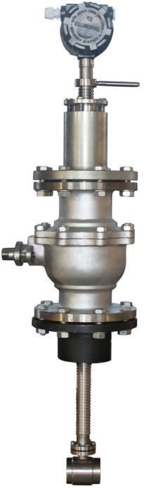
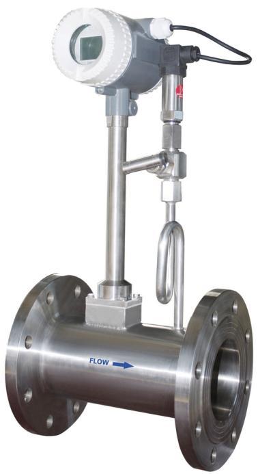
1 Vortex Flowmeter Series MTGB Vortex FlowmeterManual Dalian Metern Measurement and Control System Co.,Ltd
2 CONTENTS 1.GENERAL INFORMATION Product Description Technical Data Model and Selection Model Selection Converter Function Table CAUTIONS FOR INSTALLATION Mounting Positions Required Lengths of Straight Runs Anti-Cavitation Connections Flange Connection Wafer Connection Electrical Wiring MTGB-N: Pulse Output, Explosion Proof Model MTGB-A: Two-wire 4-20mA Output, No Local Display MTGB-B,MTGB-C Series: Local Display MTGB-B: If the display is blank, put the plug of battery into the battery socket (BAT1) MTGB-C Series MTGB-C Electrical Wiring Diagram MTGB-D: Local Display (Temperature & Pressure Compensation) MTGB-D1: Local Display (Temperature & Pressure Compensation) MTGB-D2: Local Display (Temperature & Pressure Compensation) Programming and Setup MTGB-N: No display; Pulse Output MTGB-A: No display; 4-20mA Output Zero Point Calibration Full Scale Calibration MTGB-B,MTGB-C Series: Local Display Display And Key Parameters Set Parameter Function Table MTGB-D1 with Temperature and Pressure Compensation Display and Keys Parameters Set Parameter Function Table MTGB-D2 with Temperature and Pressure Compensation Display and Keys Parameters Set User manual Engineering Menu Factory Menu
3 7. Troubleshooting Quick Installation
4 1.GENERAL INFORMATION This manual will assist you in installing, using and maintaining flow meter. It is your responsibility tomake sure that all operators have access to adequate instructions about safe operating and maintenanceprocedure. Warning For your safety, review the major warnings and cautions below before operating your equipment. 1. Use only fluids that are compatible with the housingmaterial and wetted components of your Vortex. 2. When measuring flammable liquids, observeprecautions against fire or explosion. 3. When handling hazardous liquids, always follow theliquid manufacturer's safety precautions. 4. When working in hazardous environments, alwaysexercise appropriate safety precautions. 5. Handle the sensor carefully. Even small scratchesor nicks can affect accuracy. 6. For best results, calibrate the meter at least 1 timeper year. 1.1 Product Description MTGB series Vortex flow meters are designed for measuring the volume/mass flow of liquids, gases and steambased on Karman vortex principle. Adopting advanced differential algorithm along with measurement of isolation, shielding and wave filtering,mtgb series vortex flow meters have the advantages of immunity on vibration and noise. Meanwhile, the MTGB series vortex flow meters are well guaranteed by unique sensor packaging technology. Upon receipt, examine your meter for visible damage. The Vortex is a precision measuring instrument and should be handled carefully. Remove the protective plugs and caps for a thorough inspection. If any items aredamaged or missing, contact us. Make sure the Vortex flow model meets your specific needs. For your future reference, it might be useful to recordthis information on nameplate in the manual in case it becomes unreadable on the Vortex. Refer to the nameplatefor your customized product s specification. 3
5 2.Technical Data Measuring system Application range Primary measured value Secondary measured value (1) Gas; (2) Liquid; (3) Steam Flow Rate Volume flow ; (Pressure and Temperature is available for model with compensation) Measuring accuracy Reference conditions Flow meter accuracy Flow conditions similar to EN Medium: Water / Gas Electrical conductivity: 300 μs/cm Temperature: C / F Inlet section: 10 DN Operating pressure: 1 bar / 14.5 psig For Liquid: 1.0% of rate For gas and steam: 1.5% of rate Design Modular construction The measurement system consists of a flow sensor and a signalconverter. It is available as compact and as separate version. Compact version converter N Type: Pulse output without local display A Type: 4-20mA Output without local display B Type: Local Display; Lithium Battery Power;No Output (Battery Part No.: ER26500) C Type: Local Display; 24V DC Power; 4-20mA Output; Optional Function: (1) Backup Power Supply: Lithium Battery (2) Modbus RS485 (3) Pulse Output Connection Flange: DN15-DN300 Wafer: DN15-DN300 Measurement ratio Standard 10:1 4
6 Operating conditions T1 Level: C Process temperature T2 Level: C T3 Level: C Ambient Standard (with aluminum converter housing): (all versions) C Storage temperature DN200 DN300: PN10 DN100 DN200: PN 16 EN DN15 DN80: PN 25 Other pressures on request 1/2...8": 150 lb RF ASME B16.5 Other pressures on request 1/2...8": 10 K JIS Other pressures on request Installation conditions Installation Flow direction Inlet run Outlet run Take care that flow sensor is always fully filled For detailed information see chapter "Cautions for Installation" Forward Arrow on flow sensor indicates flow direction. 10 DN 5 DN Materials Sensor housing Flanges Converter Housing SS304 Other materials on request SS304 Other materials on request Standard: polyurethane coated die-cast aluminum Process connections EN DN in PN ASME 1/2 12" in 150 lb RF JIS 1/2 12 in K Design of gasket surface RF Other sizes or pressure ratings on request Wafer DN15 DN300 5
7 Flow range Nominal Diameter Liquid Gas (mm) (in) Flow (m3/h) Flow (m3/h) 15 1/2 1.2 to to /4 1.5 to 10 8 to to to /2 2.5 to to to to /2 6.5 to to to to to to to to to to to to to to to to Note: The flow range as blow is for reference only. Consult the factory if you have special requirement. Refer to the nameplate or certificate for actual flow range. 6
8 3.Model and Selection 3.1 Model Selection MTGB Wafer Flange Pipe butt welding Thread Clamp Fixed plug-in Ball-vale plug-in Liquid Gas/Air Steam Vortex Flow Meter Description Installation type Medium -XXX Nominal diameter, For example: 200 stands for DN200 Nominal Diameter -N1 -N2 -A -B -C1 -C2 -C3 -H -D 24VDC, Pulse signal, No display 24VDC, Pulse signal, No display, Ex 24VDC, Two-wire 4-20mA output, No display Battery power, No output, Local display 24VDC, Pulse signal, RS485, Local display 24VDC, Two-wire 4-20mA signal, Local display 24VDC, Three-wire 4-20mA signal, Pulse,RS485, Local display 24VDC, 4-20mA signal, HART, Local display 24VDC, 4-20mA signal, Pulse, RS485, Compensation -T1 -T2 -T Output Signal Medium Temp Mpa 2.5Mpa 4.0Mpa 6.4Mpa Higher pressure (Maximum 32Mpa) M P T PT Differential pressure compensation Pressure compensation Temperature compensation Temperature and pressure compensation F Q S N G B Remote Submerged Reducing Corrosion-resistant Flame-proof Intrinsic safety proof Nominal Pressure Compensation type Other MTGB C2 -T2 2 PT G 7
9 3.2 Converter Function Table Converter Model C D Note: Power Supply Main Power Dual Power (Battery) Display N1 24VDC N2 24VDC Pulse Scale Pulse A 24VDC B 24VDC Output 4-20mA 2-wire 3-wire C1 24VDC C2 24VDC C3 24VDC D1 24VDC D2 24VDC N1 without Ex proof; N2,A,B,C1,C2,C3 with Ex proof. Description of the symbols: Default Function Option Modbus RS485 4.CAUTIONS FOR INSTALLATION 4.1 Mounting Positions Pipes must be fully filled with liquids. It is essential that pipes remain fully filled at all times, otherwise flow rate indications may be affected and measurement errors may be caused. Avoid Air Bubbles. If air bubbles enter a measurement pipe, flow rate indications may be affected and measurement errors may be caused. 8

10 Avoid all pipe locations where the flow is pulsating, such as in the outlet side of piston or diaphragm pumps Avoid locations near equipment producing electrical interference such as electric motors, transformers, variablefrequency, etc. Install the meter with enough room for future access for maintenance purposes Warning: Precaution for direct sunshine and rain when the meter is installed outside. 4.2 Required Lengths of Straight Runs Flow altering device such as elbows, valves and reducers can affect accuracy. See diagram below for typical flow metersystem installation. Diagram 1. Typical Flow Meter System Installation The recommended guidelines are given to enhance accuracy and maximize performance. Distance given here are minimum requirements; Double them for desired straight pipe lengths. Upstream: allow a minimum straight pipe length at least 10 times the internal diameter of the pipe. For example,with the 50mm pipe, there should be 500mm of straight pipe immediately upstream. Desired upstream straightpipe length is 1000mm. Downstream: allow a minimum straight pipe length at least 5 times the internal diameter of the pipe. Forexample, with the 50mm pipe, there should be 250mm of straight pipe immediately upstream. Desiredupstream straight pipe length is 500mm. 9
11 4.3 Anti-Cavitation Cavitation can be caused by entrained air. An amount higher than about 100 mg/l of entrained air or gas can produce error. In addition, cavitation can be caused by too little backpressure on the flow meter. For our Vortex flow meters, you should provide a backpressure (downstream pressure) of at least 1.25 times the vapor pressure, plus 2 times the pressure drop through the flow meter. See formula 1. Formula 1: Pb 1.25 Pv + 2 (Pin Pout) In formula 1: (Pb: Back pressure; Pv: Vapor Pressure; Pin: Inlet Pressure; Pout: Outlet Pressure) Create backpressure by installing a control valve on the downstream side of the meter at the proper distance detailed above. Special Notice When the fluid is liquid, to ensure accurate measurement, drain all air from the system before use. When the meter contains removable coverplates. Leave the coverplate installed unless accessory modulesspecify removal. Don t remove the coverplates when the meter is powered, or electrical shock and explosionhazard can be caused. 4.4 Connections Flange Connection Installation Flow direction Inlet run Outlet run Take care that flow sensor is always fully filled For detailed information see chapter "Cautions for Installation" Forward Arrow on flow sensor indicates flow direction. 10 DN 5 DN 10
12 DIN Flange Meter Dimensions Size Code A DIN Flange Flange Bolt Circle Bolt Hole Pressure Diameter Diameter Bolt Hole Diameter Rating (B) (PCB) Quantity (Inch) (mm) (mm) MPa (mm) (mm) (mm) 15 1/ / / / / Note: For model with temperature and pressure compensation, the flowmeter length should be increased 50mm compared to the value (A) in table above Wafer Connection Installation Flow direction Inlet run Outlet run Take care that flow sensor is always fully filled For detailed information see chapter "Cautions for Installation" Forward Arrow on flow sensor indicates flow direction. 10 DN 5 DN 11

13 Diameter Pipe D (mm) Specification H L L0 D1 D2 15 Φ Φ Φ Φ Φ Φ Φ Φ Φ Φ Φ Φ Φ Electrical Wiring Warning: Electrical Hazard Disconnect power before beginning wiring. 5.1 MTGB-N: Pulse Output, Explosion Proof Model Terminal Configuration Terminal Symbols Description + Power Supply: 24V+ - GND Pulse Output Terminal Wiring 12


14 5.2 MTGB-A: Two-wire 4-20mA Output, No Local Display Terminal Symbols Description + Power Supply: 24V+ - GND Pulse Output Terminal Wiring Terminal Configuration 5.3 MTGB-B,MTGB-C Series: Local Display Note: Terminal configuration is same for MTGB-B, MTGB-C series, but some functions are ONLY available on specified model. The table lists the function of each model. DIP Switch: K1 Function Original Pulse Output ON OFF OFF Scaled Pulse Output: 1 m3 / Pulse OFF ON OFF Scaled Pulse Output: 1L/Pulse; 10L/Pulse; OFF OFF ON Configure it in parameter setting 100L/Pulse Terminal Wiring Terminal Configuration MTGB-B: If the display is blank, put the plug of battery into the battery socket (BAT1). 13
 4-20mA Output 3 IOUT+ 24V DC+ Power Supply 4 IOUT- GND 7 +24V 24V DC+ Power Supply 8 GND GND C3 (3 wires) 4-20mA & Pulse & RS485 Output 4 IOUT- Current output")
15 5.3.2 MTGB-C Series Model Function (Optional) Terminal Code Terminal Symbols Description 7 +24V 24V DC+ Power Supply 8 GND GND C1 Pulse & RS485 Output 5 FOUT Pulse output+ 6 GND Pulse output A Rs B Rs485- MTGB-C C2 (2 wires) 4-20mA Output 3 IOUT+ 24V DC+ Power Supply 4 IOUT- GND 7 +24V 24V DC+ Power Supply 8 GND GND C3 (3 wires) 4-20mA & Pulse & RS485 Output 4 IOUT- Current output 4-20mA 5 FOUT Pulse output A RS B RS MTGB-C Electrical Wiring Diagram 14
 Terminal Configuration (1) Main Power Supply and 4-20mA Output Terminal Symbols Description + Power Supply: 24V+ - 4-20mA Current Output Terminal")
16 5.4 MTGB-D: Local Display (Temperature & Pressure Compensation) MTGB-D1: Local Display (Temperature & Pressure Compensation) Note: this converter configures 3-wire 4-20mA Output MTGB-D2: Local Display (Temperature & Pressure Compensation) Terminal Configuration (1) Main Power Supply and 4-20mA Output Terminal Symbols Description + Power Supply: 24V mA Current Output Terminal Wiring (2) Auxiliary Terminals Terminal Symbols Description v+ Power Supply: 24V+ Fout Pulse Output (Open-Collector with 1.5K Ohm Pull-up Resistor) GND 4-20mA Current Output Note: Auxiliary terminals can work ONLY when there is power supply for main power supply. 6. Programming and Setup All flowmeters are tested and calibrated prior to leaving the factory, and the unique K-factor is provided on the calibration certificate. Keep the calibration certificate well to avoid the loss of K-factor. 15
 Shut off the value where the flowmeter is installed, ensure there is no flow rate in pipe.")
17 6.1MTGB-N: No display; Pulse Output Customer should set the correct K-factor into PLC or Flow totalizer in order to get the correct flow rate. 6.2MTGB-A: No display; 4-20mA Output Only perform the Zero Point Calibration where it's necessary Zero Point Calibration (1) Shut off the value where the flowmeter is installed, ensure there is no flow rate in pipe. (2) Put high accuracy amperometer into the circuit loop as series connection. (3) Adjust the potentiometer W502 to make sure the display on amperometer is 4mA Full Scale Calibration It's ONLY available for factory; Return the flowmeter to factory for full scale calibration where is applicable. 6.3 MTGB-B,MTGB-C Series: Local Display Note: all menus are present in all signal converter versions, but some parameter settings are ONLY valid for specified models Display And Key Flow Rate Total Flow Keys (See table below for function and representation in text 16
18 Key Measuring Mode Menu Mode Sub-menu or Parameter and Data Function Mode Mode 1. Display the frequency Select menu Press 1 time, return Save the value and Enter corresponding to flow rate to menu mode, data advance to next menu 2. Enter the parameter saved setting mode For numerical values, move cursor one position to the right or left Select sub-menu or function Use cursor highlighted to change number, unit, setting Esc Return to measuring mode but prompt whether the data should be saved Return to measuring mode but prompt whether the data should be saved measuring mode but prompt whether the data should be saved Note: Data are not saved when press Esc to return to measuring mode. If the value need to be changed, press Enter to save value first Parameters Set Press Enter two times at measuring mode, it leads to Password Menu (1) Input correct password and press Enter can start parameter setting. (2) Press Enter again and no password is input can ONLY view all parameters The total menus in Parameters Set are 16, and users can access and modify these menus depending on the input password grade. See table below for more information on password grade. Table. Description of Password Grade Password Grade Password Login Privileges Grade 1 No Password Read Only Grade Read and Edit Grade Save all data as factory defaults Grade Reload factory defaults Note: Parameter setting can be ONLY performed by authorized engineer, as parameter change can affect the accuracy of the flowmeter 17
19 Menu Parameter Name Setting Method Grades Range F---01 Flow Rate Unit Select Parameter Factory ONLY 1; 2; 3 F : 1 Liter/Pulse Scaled Pulse Output Select User 10: 10 Liter/Pulse In Liters Parameter 100: 100 Liter/Pulse F---03 Damping Time Input Value User Unit: Second Value: 1-10 F---04 Maximum Flow Rate Input Value User Unit: same as Flow Rate F---05 Minimum Flow Rate Input Value User Unit: same as Flow Rate F---06 Maximum Frequency Hz Input Value User Output Accuracy: 0.1Hz F---07 Baud Rate 1200; 2400; 4800; 9600; Select User Parameter Data Format: n; 8; 1 F---08 Device Address Input Value User F---09 Frequency Output Model Select Parameter User 1; 2 F---10 Total Flow Reset Input Value User Reset the new value and press Enter to confirm the change promptly. Menu Parameter Name Setting Method Grades Range P1 Linearization of the First Row: Frequency (P1) Input Value Factory ONLY Flowcurve: point 1 Second Row: K-Factor (P1) P2 Linearization of the First Row: Frequency (P2) Input Value Factory ONLY Flowcurve: point 2 Second Row: K-Factor (P2) P3 Linearization of the First Row: Frequency (P3) Input Value Factory ONLY Flowcurve: point 3 Second Row: K-Factor (P3) P4 Linearization of the First Row: Frequency (P4) Input Value Factory ONLY Flowcurve: point 4 Second Row: K-Factor (P4) P5 Linearization of the First Row: Frequency (P5) Input Value Factory ONLY Flowcurve: point 5 Second Row: K-Factor (P5) P Average Input Value Factory ONLY First Row: Frequency (P) Second Row: K-Factor (P) 18
20 6.3.3 Parameter Function Table No. Function Settings / Descriptions F---01 Flow Rate Unit Selectable: 1, 2, 3 1: m3; 2: Liter; 3. Factory Reserved Consult the factory first to change the unit, as the K-factor should also be changed. Selectable: 1, 10, 100 F---02 Scaled Pulse Output 1: 1 liter/pulse; 10: 10 Liters/Pulse; 100: 100 Liters/Pulse In Liters Only valid for model supporting Pulse Output; and Position 3 of DIP Switch is ON, others two are OFF. F---03 Damping Time Value: 1-10 second; Recommended Value: 4 Second Flow Range F---04 Maximum Flow Rate Unit: same as Flow Rate F---05 Minimum Flow Rate Unit: same as Flow Rate Frequency Output F---06 Maximum Frequency Value: Hz Output Accuracy: 0.1Hz RS485 Communication F---07 Baud Rate Selectable: 1200; 2400; 4800; 9600; (Unit: Hz) Default Data Format: 9600, n, 8, 1 F---08 Device Address Value: F---09 Selectable: 1, 2 Frequency Output 1: Original Pulse Output without linearization Mode 2: Corrected Pulse Output after linearization Reset Total Flow F---10 Total Flow Reset Reset the new value and press Enter to confirm the change promptly. Linearization P1 Linearization of the First Row: Frequency (P1) Flowcurve: point 1 Second Row: K-Factor (P1) P2 Linearization of the First Row: Frequency (P2) Flowcurve: point 2 Second Row: K-Factor (P2) P3 Linearization of the First Row: Frequency (P3) Flowcurve: point 3 Second Row: K-Factor (P3) P4 Linearization of the First Row: Frequency (P4) Flowcurve: point 4 Second Row: K-Factor (P4) P5 Linearization of the First Row: Frequency (P5) Flowcurve: point 5 Second Row: K-Factor (P5) P Average K-Factor First Row: Frequency (P) Second Row: K-Factor (P) 19
 Current Frequency; (2) Output Current; (3) Password.")
21 6.4 MTGB-D1 with Temperature and Pressure Compensation Warning: Electrical Hazard Disconnect power before beginning wiring Display and Keys Keys (See table below for function and representation in text) Total Flow Flow Rate Operating Temperature Operating Pressure Parameters Set At main measuring mode, press S can switch to secondary measuring display, which has 3 Rows: (1) Current Frequency; (2) Output Current; (3) Password. Input the correct password, and press Enter can advance to parameter setting mode. Note: default password 00. Save the new password once it s changed. Key Measuring mode Menu mode Switch between display S pages: (1) Main Measuring Mode Select menu (2) Parameter Setting + Use cursor highlighted to change number, unit, setting < For numerical values, move cursor one position to the right or left Enter Confirm to enter the parameter setting after correct password is input Saved the parameter change At menu Reset Password, press Enter can lead to measuring mode. 20
22 6.4.3 Parameter Function Table No. Function Settings / Descriptions 1 Flow Unit Selection Flow Rate Unit: Selectable 0-6 0: m3/hr; 1: m3/min; 2: Liter/hr; 3: Liter/min 4: t/hr; 5: t/min; 6: kg/hr; 7: kg/min 2 Multi-segment Broken Lines Linearization of the Flowcurve Y: Enable the linearization of the Flowcurve N: Disable the linearization 3 Aglorithm Slecetion Selectable: : Volume flow of conventional liquids 02: Liquid volume of temperature compensation 03: Volume flow of conventional gases 04: Gas volume of compression coefficient 05: Volume flow of thermal-pressure coefficient 06: Conventional mass flow 07: Mass flow of temperature compensation 08: Mass flow of compression coefficient 09: Mass flow of multi-segment broken lines 10: Temperature compensation of saturated steam 11: Pressure compensation of saturated steam 12: Temperature and pressure compensation of overheated steam 4 Broken Line Gas-Liquid Selection Selection:0-1 0: Fluid is Gas; 1: Fluid is liquid 5 Flow Coefficient Flowmeter K-factor Unit: Pulse /m 3 It means how many pulse for one cubic meter 6 Maximum Output Flow Maximum Flow Rate 7 Platinum Resistance Selection Temperature Sensor Type. Selectable: 0-1 0: PT100; 1: PT Setting Density Set Fluid density; Unit: Kg/ m 3 9 Rest Cumulant Reset Total Flow Y: Reset total flow N: Don t reset total flow 10 Pmax Maximum Pressure: set the Max. Pressure (Unit: Kpa) 11 Pmin Maximum Pressure: set the Min. Pressure (Unit: Kpa) 12 Freq Out Rs485 Communication device address 13 Communication No. Rs485 Communication device address Optional Function 14 Qmin% Flow Cutoff: if this value is 10%, then Min. Flow=0.1*Max. Flow which means the display remains as 0 if the flow rate is less which means the display remains as 0 if the flow rate is less than Min. Flow 21
23 6.5 MTGB-D2 with Temperature and Pressure Compensation Note: all menus are present in all signal converter versions, but some parameter settings are ONLY valid for specified models Display and Keys Key Measuring Sub-menu or Function Parameter and Secondary Measuring Mode mode Mode Data Mode +/S 1. At password input mode, +/S can increase the number 2. Use </E to move cursor Change the value or select different parameter 1. Press and Hold </E can enter password input mode. (1) Press and hold </E to enter current menu For numerical </E 2. At password input mode, (2) Press and hold </E values, move press and hold +/S can back to save the data when cursor one position to secondary measuring mode the modification is finished to the right or left Press +/S and </E together to switch between Measuring Mode and Secondary Measuring Mode Note: Press +/S and </E together to switch between Measuring Mode and Secondary Measuring Mode 22
24 6.5.2 Parameters Set Table. Description of Password Mode Password Grade Password Login Privileges Level 1 22 User Menu Level 2 33 Engineering Menu Level 3 44 Factory Menu Note: parameter setting can be ONLY performed by authorized engineer, as parameter change can affect the accuracy of the flowmeter User manual No. Function Settings / Descriptions 1 0: m3/h (Nm3/h when Algorithm Selection = 2) Flow rate's Unit 1: m3/min; 2: Liter/h; 3: Liter/min; (Default: 0) 4: ton/h; 5: ton/min; 6: kg/h; 7: kg/min 0: Volume Flow 1: Mass Flow 2 2: Normative Volume Flow Algorithm Selection 3: Gas Mass Flow (Default: 0) 4: Saturated Steam Temperature Compensation 5: Saturated Steam Pressure Compensation 6: Superheated Steam Temp. and Pressure Compensation 3 Flow coefficient, default: Unit: P/m3 4 Fluid Density (kg/m ) This menu should be set when Algorithm Selection = 1 or 3 XXXX.XXXX Default: Unit: Kg/m3; 5 Full-scale flow: default Instantaneous flow corresponding to 20mA current output Unit is the same as "1" 6 Value: 0-20% Low Flow Cutoff % Default: 1%; which means the flow will be cut when it's less Default: 0% than 1%Max Flow 7 Max alarm flow When the flow rate exceed the max flow, output alarm signal Default: Unit is same as Flow rate's Unit 8 Min alarm flow When the flow rate below the min flow, output alarm signal Default: 10.0 Unit is same as Flow rate's Unit 9 Value: 2-32 Damping The damping time for current output and frequency XX Default: 4S 10 Communication address 485 Modbus device address, range 0-254, default 0 11 Password: Reset Total Flow When Reset Total Flow is required, input password 70 and press </E 23
25 6.5.4 Engineering Menu No. Function Settings / Descriptions 1 Input Signal Frequency Range Set the correct frequency range, or may cause trouble 2 Pulse Output Type Select the correct pulse output 3 Scaled Pulse Output Only valid for pulse output; 0 is not permit 4 Correction Function and Five Point Linearization corresponding Percentage (Don't change this setting or can affect the accuracy) 5 Temperature and Pressure (1) Enable: Temperature and Pressure display Display Enable/Disable (2) Disable: Temperature and Pressure will not display 6 Temperature Sensor Type PT100 PT Temperature at standard state (1) Standard Temperature: 0 (2) Standard Temperature: 20 8 Reference Pressure (1) Absolute Pressure Sensor: 0 (2) Gauge Pressure Sensor: Local Atmospheric Pressure (Unit: KPa) 9 Default Pressure For only temperature compensation type 10 Default Temperature For only pressure compensation type 11 1) Enable: input signal will be cut and ignored between Hz Interference Hz to 50.5 Hz Suppression (2) Disable: don't suppress 50 Hz Signal 12 Converter Ambient (1) -10 : normal display Temperature (2) -20 : display refresh every 8 second 24
26 6.5.5 Factory Menu Warning: ONLY Factory can modify these menus, or it can cause trouble or damage No. Function Settings / Descriptions 1 70: ave current parameter setting as initial value and save into Initial Setting based on EEPROM Register different 90: Backup all parameters to MCUF Register password 79: Reload the parameter setting from MCUF to EEPROM 2 Pt100 Calibration Connect accurate 100 Ohm Resistor and perform the calibration 3 PT200 Calibration Connect accurate 200 Ohm Resistor and perform the calibration 4 PT1000 Calibration Connect accurate 1000 Ohm Resistor and perform the calibration 5 PT2000 Calibration Connect accurate 2000 Ohm Resistor and perform the calibration 6 Max. Fluid Pressure Set the Max. Fluid Pressure 7 Max. Pressure Calibration Calibrate it when the pressure reaches steady Max. Pressure 8 Min. Fluid Pressure Set the Min. Fluid Pressure 9 Min. Pressure Calibration Calibrate it when the pressure reaches steady Min. Pressure 10 4mA Output Calibration Use high accuracy amperemeter to get 4mA Output, and perform this calibration 11 12mA Output Calibration Use high accuracy amperemeter to get 12mA Output, and perform this calibration 12 20mA Output Calibration Use high accuracy amperemeter to get 20mA Output, and perform this calibration 25

27 7. Troubleshooting Symptom Measurement is not accurate Flow rate indication is unstable No Display 1. Parameter wrong Check the parameters (Transmitter, detector factor and size) 2. Pipe is not fully filled Check if meter is fully filled 1. Vibration Problem Add support to the line near the meter to damp the vibration 2. Air Make sure fluid does not contain air bubbles when fluid is liquid 3. Amplifier location Make sure amplifier is not too close to sources of electrical outside electrical interference interference 1. No power Apply correct power 2. Incorrect power Check power value 3. Wiring connections Check power input/output connections 8. Quick Installation Flange-Style Flow Meter Installation Wafer-Style Flow Meter Installation 26
Vortex Flow Meter Wafer or Flange Connection. - Steam - Liquid - Gas
 Vortex Flow Meter Wafer or Flange Connection - Steam - Liquid - Gas Working Principle & Circuit Diagram Working Principle When a column body placed in flowing fluids in pipe, a series of vortices will
VersaFlow Vortex 100 Vortex Flow Meter Technical Datasheet. Specification. The all-in-one solution. Highlights. Industries.
 VersaFlow Vortex 100 Vortex Flow Meter Technical Datasheet 34-VF-03-05 September 3rd, 2008 Specification The all-in-one solution The VERSAFLOW is the only vortex flowmeter with integrated pressure and
Integral type Differential pressure flowmeter VNT Series
 Integral type Differential pressure flowmeter VNT Series OUTLINE VH series Wafer-Cone differential pressure flowmeter and high precision differential pressure transmitter are integrated into one flowmeter.
Wafer type. the product
 . VFM5 Vortex Flow Meter Flanged type Wafer type Insertion type VFM5 is a powerful flow meter utilizing Karman vortex theory, which can meet the requirement of measuring the flow rate of various fluids
LUGB Vortex Flowmeter
 LUGB Vortex Flowmeter Overview LUGB swirl flowmeter is also called as vortex flowmeter, it is a new of flowmeter which is developed according to fluid vibration theory, widely used for fluid measurement
T EK-COR 1100A Coriolis Mass Flowmeter
 T EK-COR 1100A Coriolis Mass Flowmeter Instruction Manual Document Number: IM-1100A NOTICE Read this manual before working with the product. For personal and system safety, and for optimum product performance,
Pro-V Multivariable Flowmeter Model M22 In-line Vortex
 Pro-V Multivariable Flowmeter Model M22 In-line Vortex Pro-V TM Advantage: Volumetric or mass flow monitoring of most liquids, gases, and steam Multivariable meter delivers mass flow, temperature, pressure,
T EK-THERMAL 1700B Thermal Mass Flowmeter
 T EK-THERMAL 1700B Thermal Mass Flowmeter Instruction Manual Document Number: IM-1700B NOTICE Read this manual before working with the product. For personal and system safety, and for optimum product performance,
For Multi-Parameter Meters see mvx
 Design Features VORTEX IN-LINE FLOW METERS For Multi-Parameter Meters see m Principles of Operation n No moving parts to wear or fail. n Electronics can be remotely mounted up to 30.5 m (0 ft). n No fluid
Coriolis Mass Flow Meter
 Coriolis Mass Flow Meter TMFW Series Mini Type Coriolis Mass Flow Meter Xi an Tosilon Automation Co., Ltd No.299, Daqing Rd, Lianhu District, Xi'an Shaanxi, China Tel: +86-29-8823 8550 info@tosilon.com;
T EK-SUB 4800C 19 mm Submersible Level Transmitter
 Technology Solutions T EK-SUB 4800C 19 mm Submersible Level Transmitter Instruction Manual Document Number: IM-4800C www.tek-trol.com Table of Contents 1 Safety Instructions... 2 1.1 Intended Use... 2
Design Features. General Description
 Model thermal Mass Flow Controllers are designed to indicate and control set flow rates of gases. The combines the characteristics and accuracy of conventional mass flow devices into a unique compact design
For Multi-Parameter Meters see mvx
 VORTEX IN-LINE FLOW METERS Design Features For Multi-Parameter Meters see mvx Principles of Operation VX No moving parts to wear or fail. Electronics can be remotely mounted up to 30.5 m (0 ft). No fluid
Pro-V Multivariable Flowmeter
 Pro-V Multivariable Flowmeter Model M23 Insertion Meter M23-V flowmeter provides cost-effective volumetric flow monitoring solution for most liquids M23-VT incorporates temperature sensing to provide a
OPTIBAR P 1010 C Technical Datasheet
 Technical Datasheet Pressure transmitter with recessed diaphragm for general applications Wide variety thanks to modular design Measuring ranges up to 250 bar / 3750 psi High overload and temperature stability
COMPAFLOW. Compressed Air. Volumetric flow. Gas. Mass flow. Steam. Net volumetric flow. Liquid
 Volumetric flow Compressed Air Mass flow Gas Net volumetric flow Steam Liquid Universal compact orifice flow meter combines a compact orifice flow sensor and sotiphicated converter One-piece flow sensor,
Electronic gas volume corrector model DGVC-04
 Electronic gas volume corrector model DGVC-04 1. Introduction The following user s manual gives information about the installation, configuration, usage and storage of the electronic gas volume corrector
SonoMeter 30 Energy Meters
 Data Sheet SonoMeter 30 Energy Meters Description The Danfoss SonoMeter 30 is a range of ultrasonic, compact energy meters intended for measuring energy consumption in heating and cooling applications
C-Flow Coriolis Mass Flow Meters
 Coriolis Mass Flow Meters Ready for Take Off The New Compact C-Flow Küppers Elektromechanik GmbH The C-Flow The C-Flow Coriolis Mass Meters consist of two components: KCE Transmitter KCM Transducer 2 KEM
ACV-10 Automatic Control Valve
 ACV-10 Automatic Control Valve Installation, Operation & Maintenance General: The Archer Instruments ACV-10 is a precision automatic feed rate control valve for use in vacuum systems feeding Chlorine,
Pressure Measurement Single-range transmitters for general applications
 Siemens A 207 Overview Application The SITRANS P Compact pressure transmitter is designed for the special requirements of the food, pharmaceutical and biotechnology industries. The use of high-grade materials
Over 20,000 Strain Gage Target flowmeters installed since 1952.
 Over 20,000 Strain Gage Target flowmeters installed since 1952. Liquid, gases, superheated and saturated steam from -320 to 500 O F and up to 15,000 psi. No frictional moving parts. Designed to withstand
TH-1800-T TRX-700-CNG Converter
 TH-1800-T TRX-700-CNG Converter low detector The CNG fuel gas flowmeter is so accurate as to meet a demand of measuring the CNG directly by making the most use of our well-established mini-thermal flowmeter
PanaFlow MV82. Insertion Style Multivariable Flowmeter. GE Measurement & Control. Key Benefits. Applications
 GE Measurement & Control PanaFlow MV82 Insertion Style Multivariable Flowmeter Key Benefits Multivariable vortex flowmeter for measuring volumetric flow, temperature, pressure, density, and mass flow using
Differential Pressure Transmiter
 Differential Pressure Transmiter Description The is an economical alternative to established differential pressure transmitters. It combines state of the art electronics and a high performance sensor;
How to specify a product. Process Sensors and Mechanical Instruments
 How to specify a product Process Sensors and Mechanical Instruments Keep the overview. Here is some guideline information on how to specify our products. Intended as supplementary help to specification
Malema Sensors M-2700 Integrated Ultrasonic Flow Meter
 Malema Sensors M-2700 Integrated Ultrasonic Flow Meter Operating Instructions TABLE OF CONTENTS Introduction............... 3 Storage and Handling........... 4 Installation Instructions........... 4 Start
Features. Description
 Features Fast response flow meter ideal for inert gas and liquid mass flow measurement applications Smart electronics permit field adjustment of critical flow meter settings Field validation of flow meter
RCD - Ultra-Rugged Differential Pressure Flowmeter
 0.15-1 to 85-600 GPM Liquids 2.5-25 to 300-1700 SCFM Gases 1/2 to 3 Line Sizes Bronze or 316-Ti Stainless Steel Mechanical Indicator, Digital Indicator, Transmitters and Switches Available Custom Calibrations
Bubble Tube Installations
 Instruction MI 020-328 September 2013 Bubble Tube Installations For Liquid Level, Density, and Interface Level Measurements 2 Contents Introduction... 5 Abbreviations... 5 Principle of Operation... 5 Alternative
Vortex flowmeters. Product family introduction Principle of operation Product review Applications Key product features
 Vortex flowmeters introduction Product review s Key product features This document should not be duplicated, used, distributed, or disclosed for any purpose unless authorized by Siemens. Page 1 Vortex
Technical Data Sheet. OPTIMASS 7000 Custody Transfer Mass Flowmeter
 Technical Data Sheet KROHNE 12/2004 7.02516.21.00 CH/GR OPTIMASS 7000 Custody Transfer Mass Flowmeter with single straight measuring tube OIML R117 Pattern Approval Accuracy classes 0.3 / 0.5 / 1.0 / 1.5
2 Overview. SITRANS P measuring instruments for pressure. Transmitters for gage and absolute pressure. Z series for gage pressure
 Z series for gage pressure Overview Design The main components of the pressure transmitter are: Brass housing with silicon measuring cell and electronics plate Process connection Electrical connection
SITRANS P measuring instruments for pressure
 SITRANS P measuring instruments for pressure Z series for gage pressure Siemens AG 008 Overview Design The main components of the pressure transmitter are: Brass housing with silicon measuring cell and
LEVIFLOW INTEGRATED FLOWMETER LFIF USER MANUAL
 LEVIFLOW INTEGRATED FLOWMETER LFIF USER MANUAL LEVIFLOW Integrated Flowmeter: LFIF-06 (10 l/min) This manual contains information necessary for the safe and proper use of the LEVIFLOW LFS flowmeter series.
7000 Series OPTIMASS Mass Flowmeters. Titanium Hastelloy Stainless Steel
 KROHNE 04/2003 7.02445.71.00 GR 7000 Series OPTIMASS Mass Flowmeters with single straight measuring tube Titanium Hastelloy Stainless Steel One tube no limits No limits with tube material No limits with
Installation, operating and maintenance Instructions for Seemag bypass level indicator
 Issue: S Date: 05-09-14 Type G35 General information The Seetru bypass magnetic level indicator, abbreviate SEEMAG, serves to show the filling level of fluids in tanks, basins, tubes etc. The Seemag operates
Excellent Vortex Flowmeter INSERTION Type BATTERY POWERED EX DELTA
 Excellent Vortex meter INSERTION Type BATTERY POWERED EX DELTA GENERAL SPECIFICATION GS.No.GBD604E-6 GENERAL The battery-powered EX DELTA is a dedicated on site monitor with a wide variety of applications
Shanghai AEAD Technology Co., Ltd Professional Manufacturer of Flow, Level, Pressure, Temperature
 Shanghai AEAD Technology Co., Ltd Professional Manufacturer of Flow, Level, Pressure, Temperature Tel: 86-21-5197 8797 Fax: 86-21-5197 8799 Email: shaead@163.com Site: www.shaead.com/english Flow Meter
OPTISWIRL 4070 C. Handbook. Vortex-flowmeter
 OPTISWIRL 4070 C Handbook Vortex-flowmeter CONTENTS OPTISWIRL 4070 C 1 Safety... 5 1.1 Intended use... 5 1.2 Certifications... 6 1.3 Safety instructions from the manufacturer... 6 1.3.1 Notes about the
Flow metering in gases Introduction to COMBIMASS family
 Flow metering in gases Introduction to COMBIMASS family - physical principle, basic information - different types of instruments, pricing & delivery time Sales Training Germany October 17 th to 19 th,
DTG - LCD Digital Temperature Gauge USER MANUAL
 DTG - LCD USER MANUAL Page 1 of 7 USERS GUIDE page 1. Description 3 2. Function 3 3. Safety Instruction 3 3.1. Safety Conventions 3 3.2. Proper Use 3 4. Installation 4 4.1. Unpacking 4 4.2. Storage 4 4.3.
Instructions for SMV 3000 Multivariable Configuration (MC) Data Sheets
 Data Sheets") Instructions for SMV 3000 Multivariable Configuration (MC) Data Sheets Similar to the TC option for ST 3000 transmitters, the MC option for the SMV 3000 provides a service to our customers which results
Instructions for SMV 3000 Multivariable Configuration (MC) Data Sheets Similar to the TC option for ST 3000 transmitters, the MC option for the SMV 3000 provides a service to our customers which results
SPECIFICATIONS ATTENTION
 VPS 504 S06 Installation Manual - P/N 80122 - Ed. 01/09 VPS 504 S06 and S05 Valve Proving System Installation Instructions VPS 1 6 Gases Natural gas, air and other inert gases. NOT suitable for butane
Flow VA 520. incl. temperature measurement. Intelligent solutions for ac- for compressed air and gases R 1/4 (DN 8) DN 15 R 3/4 (DN 20) DN 25
 DN 15 R 3/4 (DN 20) DN 25") VA 520 incl. temperature R 1/4 (DN 8) DN 15 R 3/4 (DN 20) DN 25 R 1 1/4 (DN 32) DN 40 R 2 (DN 50) Intelligent solutions for ac- for compressed air and gases work according to the approved calorimetric
VA 520 incl. temperature R 1/4 (DN 8) DN 15 R 3/4 (DN 20) DN 25 R 1 1/4 (DN 32) DN 40 R 2 (DN 50) Intelligent solutions for ac- for compressed air and gases work according to the approved calorimetric
TRZ 03-K Volumeter. Proven Technology. Superior Performance. TRZ 03-K Volumeter is a Turbine Gas Flowmeter for Secondary Gas Metering.
 TRZ 0-K Volumeter TRZ 0-K Volumeter is a Turbine Gas Flowmeter for Secondary Gas Metering. TRZ 0-K Turbine Gas Flowmeter continues the tradition of Honeywell s field-proven turbine meter technology, delivering
VBS-9263 Series. Application. Features. Applicable Literature
 TAC 1354 Clifford Avenue P. O. Box 2940 Loves Park, IL 61132-2940 www.tac.com VBS-9263 Series 1/2" and 3/4" Screwed NPT 316 Stainless Steel Stem Up Closed, Two-Way Valves General Instructions Application
High-performance submersible pressure transmitter For level measurement Model LH-10
 Electronic pressure measurement High-performance submersible pressure transmitter For level measurement Model LH-10 WIKA data sheet PE 81.09 Applications Level measurement in rivers and lakes Deep well
SCOPE OF THIS GUIDE STARTING-UP. 1 Check mini CORI-FLOW functional properties
 Quick Installation Guide Doc nr.: 9.17.052H Date: 10-12-2015 SCOPE OF THIS GUIDE mini CORI-FLOW instruments are highly accurate instruments for measuring and controlling the mass flow rate of liquids and/or
Level transmitter LT 100
 KROHNE 09/2001 7.02363.21.00 GR/PRINTO Level transmitter LT 100 Status: 10/99 Variable area flowmeters Vortex flowmeters Flow controllers Electromagnetic flowmeters Ultrasonic flowmeters Mass flowmeters
Mass Flow Meter (MFM) for gases
 for gases") Mass Flow Meter (MFM) for gases Type can be combined with Inline MFM for nominal flow rates from 25 l N /min to 1,500 l N /min; 1/4 to 3/4 High accuracy Fast settling time Fieldbus option Special version
Mass Flow Meter (MFM) for gases Type can be combined with Inline MFM for nominal flow rates from 25 l N /min to 1,500 l N /min; 1/4 to 3/4 High accuracy Fast settling time Fieldbus option Special version
780S Ultra High Purity Series
 Smart Ultra High Purity Thermal Gas Mass Flow Meter Features Measures mass flow directly, no seperate temperature or pressure inputs required Field adjustment of critical flow meter settings via on-board
Mass Flow Controller (MFC) for Gases
 for Gases") Mass Flow Controller (MFC) for Gases Bypass MFC with capillary technology for nominal flow rates from 5 ml N /min to 15 l N /min Applicable for aggressive gases Compact design and digital communication
Mass Flow Controller (MFC) for Gases Bypass MFC with capillary technology for nominal flow rates from 5 ml N /min to 15 l N /min Applicable for aggressive gases Compact design and digital communication
VORTEX-STREET FLOWMETER OPERATING MANUAL
 VORTEX-STREET FLOWMETER OPERATING MANUAL 1 Contents 1. Overview...2 2. Measuring principle...2 3. Technical parameter...2 4. Guide for lectotype...3 5. Installation methods and steps...6 6. Connection
GFM. Typical Aluminum GFM Mass Flow Meter NIST MASS FLOW METERS. Principles of Operation. Design Features
 Design Features Rigid metallic construction. Maximum pressure of 1000 psig (70 bars). Leak integrity 1 x 10⁻⁷ of helium. NIST traceable certification. Built-in tiltable LCD readout. 0-5 Vdc and 4-20 ma
Aperval Pressure Regulators
 Pressure Regulators Pressure regulators is pilot-controlled pressure regulator for medium and low pressure applications. is normally a fail to open regulator and specificaly will open under the following
Instruction Manual Differential Pressure Transmitter
 DE61 Instruction Manual Differential Pressure Transmitter Table of Contents 1. Safety Instructions 2. Intended Applications 3. Product Description and Functions 4. Installation 5. Commissioning 6. Maintenance
CCT-7320/ROC-2313 Reverse Osmosis Controller
 CCT-7320/ROC-2313 Reverse Osmosis Controller 1 General The instrument is a combined control instrument of a reverse osmosis controller and an on-line conductivity instrument. It can perform the operation
The affordable consumption counter for compressed air and gases R 3 /4 (DN 20)
") VA 420 new The affordable consumption counter for compressed air and gases R 1 /4 (DN 8) DN 15 R 3 /4 (DN 20) DN 25 R 1 1 /4 (DN 32) DN 40 R 2 (DN 50) With mit und and ohne without Flansch flange Intelligent
VA 420 new The affordable consumption counter for compressed air and gases R 1 /4 (DN 8) DN 15 R 3 /4 (DN 20) DN 25 R 1 1 /4 (DN 32) DN 40 R 2 (DN 50) With mit und and ohne without Flansch flange Intelligent
AMS 2710 PCB pressure sensor module with V output
 FEATURES Universal pressure sensor module with 0.. 10 V voltage output Fully calibrated and temperature compensated sensor module Variants for (bidirectional) differential, gage, absolute and barometric
Pro-V Multivariable Flowmeter Model M22 In-line Vortex
 Pro-V Multivariable Flowmeter Model M22 In-line Vortex Pro-V TM Advantage: Volumetric or mass flow monitoring of most liquids, Multivariable meter delivers mass flow, temperature, pressure, and density
Technical Manual. Liquid Level Transmitter CT801-LB/S
 CT801-LB/S Technical Manual SAS au Capital de 2 158 244-444 871 933 R.C.S. Bourges - APE : 2651B Headquarter : 9, rue Isaac Newton - 18000 Bourges - France Technical Manual CT801-LB/S 1 st Edition Released
TEK-SUB 4800B. Submersible Level Transmitter. Flow Level Temperature Pressure Valves Analyzers Accessories TekValSys LEVEL
 Technology Solutions TEK-SUB 4800B Submersible Level Transmitter LEVEL Flow Level Temperature Pressure Valves Analyzers Accessories TekValSys Introduction The Tek-Sub 4800B Submersible Level Transmitter
x act i Precision Pressure Transmitter for Food Industry, Pharmacy and Biotechnology Stainless Steel Sensor accuracy according to IEC 60770: 0.
 Precision Pressure Transmitter for Food ndustry, Pharmacy and Biotechnology Stainless Steel Sensor accuracy according to EC 60770: 0. % FSO Nominal pressure from 0... 400 mbar up to 0... 40 bar Output
GA24 Technical Datasheet
 GA24 Technical Datasheet Variable-area flowmeter Sturdy construction for several applications Local indication without auxiliary power Replaceable mounting parts KROHNE CONTENTS GA24 1 Product features
Application Worksheet
 Application Worksheet All dimensions are nominal. Dimensions in [ ] are in millimeters. Service Conditions Medium Through Valve: Required C v : Temperature Maximum: Minimum: Normal: Flow Maximum: Minimum:
VB-7213 Series. Application. Features. Applicable Literature. 1/2" to 2" Screwed NPT Stem Up Open, Two-Way Valves General Instructions
 VB-7213 Series 1/2" to 2" Screwed NPT Stem Up Open, Two-Way Valves General Instructions Application VB-7213 series single seat, stem up open, two-way valves control water from 20 to 281 F (-7 to 138 C)
2-Port Seat Valves with Flange, PN 16
 4 45 2-Port Seat Valves with Flange, PN 6 VVF45... dular cast iron EN-GJS-400-5 valve body DN 50...50 k vs 9...00 m /h Can be equipped with SKB...- or SKC...- electrohydraulic actuators Use For use in
3000 Series OPTIMASS Mass Flowmeter. Stainless Steel Hastelloy
 KROHNE 07/2005 7.02446.25.00 GR 3000 Series OPTIMASS Mass Flowmeter with single Z-shaped measuring tube Stainless Steel Hastelloy Status: 10/99 One tube no limits No limits with tube material No limits
Expert Hydrostatic Level Transmitters
 Expert Hydrostatic s General Features MJK Expert hydrostatic level transmitters are designed for level measurement by submerging the transmitter in open channels, drains and tanks. Expert hydrostatic level
Variable Area Flow Meters
 PDF Published May, 04 Variable Area Flow Meters Chemline F Series Variable Area Flow Meters are ideal for plastic piping. They provide a combination of accurate visual flow rate measurement and clear flow
L (up to 25 m) Electronic part. working temp.: Ñ IP 66 / IP67. Mounting bracket ÐÑ. Sensor type. working temp.:
 Electronic part. working temp.: Ñ IP 66 / IP67. Mounting bracket ÐÑ. Sensor type. working temp.:") Smart level probe type APC-2000ALW/L Programmable zero shift, range and damping ratio 4...20 ma output signal + HART protocol Accuracy 0,16% Local display Intrinsic safety certificate (ATEX, IECEx) II
Smart level probe type APC-2000ALW/L Programmable zero shift, range and damping ratio 4...20 ma output signal + HART protocol Accuracy 0,16% Local display Intrinsic safety certificate (ATEX, IECEx) II
CAST IRON SAFETY VALVE TYPE 6301
 CHARACTERISTICS The 6301 safety valve is dedicated to protect the equipment from potential overpressure. This is an automatic device that closes when the pressure conditions are back to normal. It is a
Mass Flow Controller (MFC) for Gases
 for Gases") Mass Flow Controller (MFC) for Gases Type 8713 can be combined with... Direct flow measurement by MEMS- Technology for nominal flow rates from 1 ml N /min to 8 l N /min (N 2 ) High accuracy and repeatability
Mass Flow Controller (MFC) for Gases Type 8713 can be combined with... Direct flow measurement by MEMS- Technology for nominal flow rates from 1 ml N /min to 8 l N /min (N 2 ) High accuracy and repeatability
T EK-COR 1100A. Coriolis Mass Flowmeter. FLOW. Technology Solutions
 Technology Solutions T EK-COR 1100A Coriolis Mass Flowmeter FLOW www.tek-trol.com Flow Level Temperature Pressure Valves Analyzers Accessories TekValSys Introduction There can often be more than one type
VB-7263 Series. Application. Features. Applicable Literature
 TAC 1354 Clifford Avenue P. O. Box 2940 Loves Park, IL 61132-2940 www.tac.com VB-7263 Series 1/2" to 2" Screwed NPT Stainless Steel Trim with Teflon Disc Stem Up Closed, Two-Way Valves General Instructions
Quick Installation Guide Doc nr.: C Date:
 Quick Installation Guide Doc nr.: 9.17.093C Date: 13-05-2016 SCOPE OF THIS GUIDE mini CORI-FLOW instruments are highly accurate instruments for measuring and controlling the mass flow rate of liquids and/or
MDM490 Piezoresistive Differential Pressure Transmitter
 Features MDM490 Piezoresistive Differential Pressure Transmitter Full stainless steel construction, compact size, easy installation; Laser welding, full-sealed construction; protection IP65; Using piezoresistive
Dival 600. Pressure Regulators
 Dival 600 Pressure Regulators Pressure regulators Dival 600 Dival 600 series pressure regulators are direct acting devices for low and medium pressure applications controlled by a diaphragm and counter
Vortex Meters for Liquids, Gas, and Steam
 A Measuring Principle Comes of Age: Vortex Meters for Liquids, Gas, and Steam Dipl.-Hyd. Oliver Seifert, Product Management Vortex Meters at Flowtec AG, and Ellen-Christine Reiff, M.A., Editor s Office,
Liquid level instruments BM 24 /BM 51
 KROHNE 09/2001 7.02362.21.00 GR/PRINTO Liquid level instruments / Status: 10/99 Variable area flowmeters Vortex flowmeters Flow controllers Electromagnetic flowmeters Ultrasonic flowmeters Mass flowmeters
ABB MEASUREMENT & ANALYTICS DATA SHEET. WaterMaster FEW530 Electromagnetic water meter
 ABB MEASUREMENT & ANALYTICS DATA SHEET WaterMaster FEW530 Electromagnetic water meter 2 WATE RMASTE R F E W 530 ELECT ROMAGNE TIC WATE R ME TE R DS/FE W530/FE T3 -E N RE V. A Measurement made easy Cost
Certified according to DIN EN ISO 9001 Technical Datasheet TRICOR Series Mass Flow Meters
 www.kem-kueppers.com info@kem-kueppers.com Certified according to DIN EN ISO 9001 Technical Datasheet TRICOR Series Mass Flow Meters Description The Tricor Mass Flow Meters measure simultaneously mass
SSL. Smart Valve Positioner.
 Smart Valve Positioner Smartest valve control device meeting a dynamic performance and a precise setting with a piezoelectric technology and an optimized auto-calibration program Features Auto-Calibration
Flow Measurement SITRANS F X
 Overview Using a vortex flowmeter with integrated pressure and temperature compensation such as the allows you not only to lower installation costs but also increase the measuring accuracy of the measuring
The M-Series Eletta Flow Meter High accuracy DP Flow Meter with multiple functions
 The M-Series Eletta Flow Meter High accuracy DP Flow Meter with multiple functions Flow Meter with multiple functions for gases and liquids M3 The M-series Flow Meter, with its versatile and user-friendly
2-Port Seat Valves with Flange, PN 16
 4 40 2-Port Seat Valves with Flange, PN 6 VVF4... Grey cast iron EN-GJL-250 valve body DN 50...50 k vs 9...00 m /h Can be equipped with SQX- electromotoric or SKD...-, SKB...- or SKC...- electrohydraulic
DK46 - DK800 Supplementary instructions
 DK46 - DK800 Supplementary instructions Variable area flowmeter Device category II2G with electrical internals Additional Ex manual KROHNE CONTENTS DK46 - DK800 1 Safety instructions 3 1.1 General... 3
High-performance submersible pressure transmitter For level measurement Model LH-10
 Electronic pressure measurement High-performance submersible pressure transmitter For level measurement Model LH-10 WIKA data sheet PE 81.09 Applications Level measurement in rivers and lakes Deep well
RMG Meßtechnik GmbH. Publication No E
 Electronic Turbine Meter TERZ 94 RMG Meßtechnik GmbH Publication No. 3.174-E P.O.ox 280 35502 utzbach (Germany) Tel.: +49 (0)6033 897-0 Fax: +49 (0)6033 897-130 E-mail: messtechnik@rmg.de Internet: http://www.rmg.de
VB-7273 Series. Application. Features. Applicable Literature
 VB-7273 Series 1/2" to 2" Screwed NPT Stainless Steel Trim Stem Up Open, Two-Way Valves General Instructions Application VB-7273 series single seat, stem down to close, two-way valves control water from
Model GP PRESSURE REDUCING VALVE Installation & Operation Manual
 Model GP-2000 PRESSURE REDUCING VALVE Installation & Operation Manual Please read this bulletin thoroughly before using the pressure reducing valve, so that you may do so correctly and safely. Please carefully
x act i Precision- Pressure Transmitter for Food Industry, Pharmacy and Biotechnology Stainless Steel Sensor
 Precision- Pressure Transmitter for Food ndustry, Pharmacy and Biotechnology Stainless Steel Sensor accuracy according to EC 60770: 0. % FSO Nominal pressure from 0... 400 mbar up to 0... 40 bar Output
Vortex Flowmeter EF73
 () 26 May 2011 ISO 9001/ ISO 14001 Kakogawa, Japan is approved by LRQA LTD. to ISO 9001/14001 Vortex Flowmeter EF73 Copyright 2009 by TLV CO., LTD. All rights reserved Rev 2-2009 Contents Contents... 2
SITRANS F C MASSFLO. MASS flowmeters Sensor type MASS MC1 DN 50 - DN 100. Manual, supplement *083R9505* Order no.: FDK:521H1145
 s Manual, supplement SITRANS F C MASSFLO MASS flowmeters [ ] Order no.: FDK:521H1145 SFIDK.PS.28.P3.2 - A5E253681 *83R955* Contents Page Introduction... 2 Siemens Flow Instruments range of coriolis mass
VB-7211 Series. Application. Features. Applicable Literature. 1/2" to 1-1/4" Union End NPT Stem Up Open, Two-Way Valves General Instructions
 TAC 1354 Clifford Avenue P. O. Box 2940 Loves Park, IL 61132-2940 www.tac.com VB-7211 Series 1/2" to 1-1/4" Union End NPT Stem Up Open, Two-Way Valves General Instructions Application VB-7211 series stem
High-performance submersible pressure transmitter For level measurement Model LH-20
 Electronic pressure measurement High-performance submersible pressure transmitter For level measurement Model LH-20 WIKA data sheet PE 81.56 Applications Deep well and borehole measurements Groundwater
JUMO dtrans p30 Pressure Transmitter
 609 Fulda, Germany Postal address: 605 Fulda, Germany Phone: +49 661 600-0 Fax: +49 661 600-607 Phone: +44 179 6 55 Data Sheet 40466 Page 1/6 JUMO dtrans p0 Pressure Transmitter General application Pressure
Norval Pressure regulator
 Norval Pressure regulator NORVAL Classification and Field of Application The NORVAL is a downstream pressure regulator, self actuated, spring loaded for medium and low pressure applications. It is suitable