FLIGHTFORCE MICRO DRONE. For ages 14+
|
|
|
- Pierce Edwards
- 6 years ago
- Views:
Transcription

1 FLIGHTFORCE MICRO DRONE For ages 14+
2 TABLE OF CONTENTS Warnings and Cautions....2 FCC Information Location of Parts and Controls Controller Battery Installation Charging the Micro Drone Battery Syncing the Micro Drone...21 Preparing for Flight Flying Tips Recognizing the Front and Rear of the Micro Drone /4 Channel Select Channel Flight Controls (Advanced Flying) Channel Flight Controls (Beginner Flying)...31 Switching To Medium & High Speed Mode Understanding Trim Adjustments Level Surface Gyro Calibration Performing a 360º Stunt Roll Low Battery Warning Replacing The Propeller Blades Troubleshooting...41 Care and Maintenance Micro Drone Specifications Warranty
3 CAUTION TO REDUCE THE RISK OF ELECTRIC SHOCK, DO NOT REMOVE COVER. THERE ARE NO SERVICEABLE PARTS INSIDE. TO REDUCE THE RISK OF FIRE OR ELECTRIC SHOCK, DO NOT EXPOSE THIS UNIT TO RAIN OR MOISTURE. The lightning flash with arrow-head symbol within an equilateral triangle is intended to alert the user to the presence of uninsulated dangerous voltage within the unit s enclosure that may be of sufficient magnitude to constitute a risk of electric shock. The exclamation point within an equilateral triangle is intended to alert the user to the presence of important operating and maintenance (servicing) instructions in the literature accompanying the unit. IMPORTANT SAFETY INSTRUCTIONS All of the safety and operating instructions should be read, adhered to and followed before the unit is operated. SAVE THESE INSTRUCTIONS 2 3
4 MICRO DRONE WARNINGS: 1. The Micro Drone is designed for INDOOR or OUTDOOR flight. 2. The Micro Drone s blades revolve at high speeds and can cause damage to the user, spectators and animals. Stand away from the Micro Drone to reduce the risk of getting into the flight path and always maintain visual contact with the Micro Drone while flying. 3. Warn spectators that you will be flying your Micro Drone so that they are aware of its position. 4. Before flight, inspect the rotor blades to make certain that the blades are securely fastened to the Micro Drone. 5. Before flying check your local laws and regulations pertaining to drone usage. 6. It is recommended to operate the Micro Drone in a wide open space. The ideal space should have a 200-foot radius. 7. Parental guidance or adult supervision is suggested at all times. 8. If you are flying the Micro Drone with others, make sure all spectators are behind you. 9. For best performance, it is recommended that you operate the Micro Drone in zero wind conditions, as wind can greatly affect the performance of the aircraft. CAUTION: DO NOT ATTEMPT TO FLY THE MICRO DRONE IF THERE IS RAIN, SNOW, HEAVY WINDS, THUNDER OR LIGHTNING OUTDOORS. IT COULD DAMAGE YOUR PRODUCT AND MAY CAUSE BODILY HARM. WARNING DO NOT FLY THE DRONE IN FOUL WEATHER! 4 5
5 WARNING! Choking/Cutting Hazard. Small Parts/Sharp Rotor Blades. Keep hands, hair and loose clothing away from the propeller when the power switch is turned to the ON position. Turn off the controller and Micro Drone power switches when not in use. Not suitable for children under 14 years old. Parental supervision recommended when flying the Micro Drone. BATTERY WARNINGS RECHARGEABLE BATTERY (MICRO DRONE): This device contains a non-removable Lithium-Polymer battery. The included charger is built specifically for the Micro Drone Li-Poly battery. Do not use it to charge any other battery. The battery must be recycled or disposed of properly. Contact your local waste management office for information on battery recycling or disposal. BC CONTROLLER BATTERIES: New alkaline batteries are recommended for maximum performance. Do not mix alkaline, standard (carbon-zinc) and rechargeable batteries (Nickel Metal Hydride). Do not mix old and new batteries. Non-rechargeable batteries are not to be recharged. 6 7
6 Rechargeable batteries are to be removed from the item before being charged (if removable). Rechargeable batteries are only to be charged under adult supervision. Exhausted batteries should be removed immediately and must be recycled or disposed of properly according to state or local government ordinances and regulations. The supply terminals are not to be short-circuited. Only batteries of the same or equivalent type as recommended are to be used. Batteries are to be inserted with the correct polarity. Do not dispose batteries in a fire - batteries may leak or explode. DANGER To reduce the risk of electric shock, burns, fire or injury: 1. Do not use while bathing or in a shower. 2. Do not place or store unit where it can fall or be pulled into a tub or sink. 3. Do not place in, drop or submerge in water or other liquid. 4. Do not reach for a unit that has fallen into water. Unplug it immediately. 5. Care should be taken so that objects do not fall and liquids are not spilled onto the unit. 8 9
7 WARNING 1. Close supervision is necessary when this appliance/ product is used by or near children or mentally disabled individuals. 2. Use this unit only for its intended use as described in this manual. 3. Unplug this unit during lightning storms or when unused for long periods of time. 4. Never drop or insert an object into any opening. 5. Protect the power cord from being walked on or pinched, particularly at plug outlets, convenience receptacles and the point where it exits the unit. 6. Do not allow cord to touch hot surfaces. Wrap cord loosely around the unit when storing. 7. The unit should be situated away from direct sunlight or heat sources such as radiators, electric heaters, heat registers, stoves, or other units (including amplifiers) that produce heat. Avoid placing on top of stereo equipment that radiates heat. 8. Never block the air openings of the unit with materials such as clothing, plastic bags or papers, or place it on a soft surface such as a bed or couch, where the air openings may be blocked. 9. Do not overload the electrical outlet. Use only the power source as indicated. 10. Do not carry this unit by its cord or use the cord as a handle. 11. Never operate this unit if it has a damaged cord or plug, if it is not working properly, or if it has been dropped or damaged, or dropped into water. If the unit s power supply cord or plug is damaged, do not attempt to fix it yourself. 12. To avoid the risk of electric shock, do not disassemble or attempt to repair the unit. Incorrect repair can cause risk of electric shock or injury to persons when the unit is used. 13. Do not operate in the presence of explosive and/or flammable fumes. 14. Never remove the plug from the outlet by pulling the power cord
8 FCC INFORMATION Caution: Changes or modifications not expressly approved by the party responsible for compliance could void the user s authority to operate the equipment. This equipment has been tested and found to comply with the limits for a Class B Digital Device, pursuant to Part 15 of the FCC Rules. These limits are designed to provide reasonable protection against harmful interference in a residential installation. This equipment generates, uses, and can radiate radio frequency energy and, if not installed and used in accordance with the instructions, may cause harmful interference to radio communications. However, there is no guarantee that interference will not occur in a particular installation. If this equipment does cause harmful interference to radio or television reception, which can be determined by turning the equipment off and on, the user is encouraged to try to correct the interference by one or more of the following measures: Reorient or relocate the receiving antenna. Increase the distance between the equipment and receiver. Connect the equipment to an outlet on a circuit different from that to which the receiver is connected. Consult the dealer or an experienced radio/tv technician for help. This equipment complies with Part 15 of the FCC Rules. Operation is subject to the following two conditions: 1. This equipment may not cause harmful interference. 2. This equipment must accept any interference received, including interference that may cause undesired operation. Modifications not authorized by the manufacturer may void the user s authority to operate this device
9 NOTES NOTES 14 15
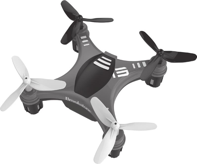
10 LOCATION OF PARTS AND CONTROLS 1. Front Rotor Blades (2) 5. Landing Gear 2. Front LED Indicator (2) 6. On/Off Switch 3. Rear LED Indicator (2) 7. Charging Socket 4. Rear Rotor Blades (2) LOCATION OF PARTS AND CONTROLS 8. On/Off Switch 12. Backward Trim Button 9. Left Trim Button 13. Forward Trim Button 10. Right Trim Button 11. Direction Control Stick 14. Throttle Control Stick 15. Power LED Indicator
11 CONTROLLER BATTERY INSTALLATION 1. Unscrew the battery cover from the back of the controller as shown in figure A. 2. Install 2 AAA alkaline batteries (not included) into the controller as shown in figure B. 3. Replace the battery cover. 4. Turn over the controller and turn the ON/OFF SWITCH to the ON position. The POWER LED INDICATOR will flash red to indicate the batteries are installed correctly. CHARGING THE MICRO DRONE BATTERY 1. Switch the Micro Drone OFF. Connect the included USB cable to the unit making sure the arrow side of the connector is on top side facing the top of the Micro Drone as shown in figure C. Note: The USB plug fits into the CHARGING SOCKET in one way only. Do not force it. Improper connection will damage the Micro Drone. Arrow Mark Fig. A Fig. B Fig. C 18 19
12 2. Connect the USB end of the cable to your computer s USB port as shown in figure D. SYNCING THE MICRO DRONE Important! When syncing the Micro Drone with the controller, always make sure that the Micro Drone is on a flat level surface and that your digital trim settings are in the center position. This ensures that the 6-Axis gyro is properly programmed to mimic your trim settings. The Micro Drone utilizes an automatic 2.4Ghz channel selection system that allows up to 8 people to fly side by side in the same wireless range with no interference. Fig. D 3. The red LED on the USB plug turns on when charging is complete. Average charging time is 40 minutes. FOR ONE-PERSON PLAY 1. Before starting, make sure that the power switches on both the controller and the Micro Drone are in the OFF position. Make sure that there are no other 2.4Ghz devices in the area. Note: The red LED on the USB plug turns on when 2. Turn the Micro Drone ON and set it down on a flat connected to a power source. When the USB plug is surface. The FRONT AND REAR LED INDICATORS will connected to the Micro Drone, the red LED will turn off. begin to flash rapidly. When the Micro Drone is fully charged the red LED will 3. Turn the controller ON, one beep will sound. The turn on. A full charge will allow for about 5-6 minutes of FRONT AND REAR LED INDICATORS will flash slowly. flight time. Unplug the charging cord when not in use
13 4. Push the THROTTLE CONTROL STICK all the way forward (one beep will sound) and then pull the THROTTLE CONTROL STICK all the way back. A second beep will sound and the FRONT AND REAR LED INDICATORS will be solid, indicating the controller and the Micro Drone are successfully synced. If not, repeat above steps. FOR MULTI-PERSON PLAY 5. Before starting, make sure that the power switches on both the controller and the Micro Drone are in the OFF position. Make sure that there are no other 2.4G devices in the area. 6. Each person needs to sync their Micro Drone at a different time to avoid interference. Follow steps 1 to 4 above ensuring that no one else is syncing at the same time. 7. After syncing, each player s Micro Drone should be left ON until all players have synced their Micro Drones. 8. Should there be interference, all players must turn off their controllers and Micro Drone for up to 60 seconds and then begin the syncing process again. PREPARING FOR FLIGHT 1. Verify that there are 2 AAA batteries inside the remote control unit and the Micro Drone has been fully charged. 2. Confirm your Micro Drone and controller are both turned on. 3. Make sure to be in a large space with an open radius of at least 50 feet. 4. Make sure the empty space has no obstacles or water close by. 5. Place the Micro Drone on a clean, flat surface before take-off. CAUTION: DO NOT ATTEMPT TO FLY THE MICRO DRONE IF THERE IS RAIN, SNOW, HEAVY WINDS, THUNDER OR LIGHTNING OUTDOORS. IT COULD DAMAGE YOUR PRODUCT AND MAY CAUSE BODILY HARM
14 FLYING TIPS It is recommended to operate the Micro Drone in a wide open space. The ideal space should have a 200-foot radius. Parental guidance or adult supervision is suggested at all times. If you are flying the Micro Drone with others, make sure all spectators are behind you. For best performance, it is recommended that you operate the Micro Drone in zero wind conditions, as wind can greatly affect the performance of the aircraft. RECOGNIZING THE FRONT AND REAR OF THE MICRO DRONE The drone has a front and a rear. The front and forward-facing direction of the Micro Drone is the side with two gray propellers as shown in figure E. The LED indicators on the front of the Micro Drone are white. The rear and backwards-facing direction of the Micro Drone is the side with two black propellers as shown in figure E. The LED indicators on the rear of the Micro Drone are red. Front Fig. E Rear 24 25
15 3/4 CHANNEL SELECT The Micro Drone can be controlled in 3 Channel mode (beginner) or 4 Channel mode (advanced flying). The Micro Drone default setting is 4 Channel mode. TO CHANGE TO 3 CHANNEL MODE After syncing the Micro Drone and controller, press and hold the DIRECTION CONTROL STICK on the right side of the controller straight down for 3 seconds (as shown in figure F); a long beep will sound indicating the Micro Drone is now in 3 Channel mode. TO CHANGE TO 4 CHANNEL MODE Press and hold the DIRECTION CONTROL STICK on the right side of the controller straight down for 3 seconds (as shown in figure F); a long beep will sound indicating the Micro Drone is now in 4 Channel mode. Press and hold for 3 seconds Fig. F 4 CHANNEL FLIGHT CONTROLS (ADVANCED FLYING) Below is a list of basic flight functions. While learning to fly the Micro Drone, it is best to start in a large space until you get used to the basic controls. As you master flying your Micro Drone, you can move to more advanced maneuvering techniques. 1. Move the THROTTLE CONTROL STICK upwards to increase the speed of the propellers and the Micro Drone will accelerate upwards and ascend. Move the THROTTLE CONTROL STICK down to decrease the speed and the Micro Done will decelerate and descend (see figure G). Fig. G Bottom of Controller 26 27
16 2. While in the air, move the THROTTLE CONTROL STICK left and the Micro Drone will rotate left. Move the THROTTLE CONTROL STICK right and the Micro Drone will rotate right (see figure H). 3. While in the air, move the DIRECTION CONTROL STICK up and the Micro drone will move forward. Move the DIRECTION CONTROL STICK down and the Micro Drone will move backward (see figure I). Fig. H Fig. I 28 29
17 4. While in the air, move the DIRECTION CONTROL STICK left and the Micro Drone will bank to the left. Move the DIRECTION CONTROL STICK right and the Micro Drone will bank to the right (see figure J). 3 CHANNEL FLIGHT CONTROLS (BEGINNER FLYING) Below is a list of basic flight functions. While learning to fly the Micro Drone, it is best to start in a large space until you get used to the basic controls. As you master flying your Micro Drone, you can move to more advanced maneuvering techniques. 1. Move the THROTTLE CONTROL STICK upwards to increase the speed of the propellers and the Micro Drone will accelerate upwards and ascend. Move the THROTTLE CONTROL STICK down to decrease the speed and the Micro Drone will decelerate and descend (see figure K). Fig. J Fig. K 30 31
18 2. While in the air, move the DIRECTION CONTROL STICK left and the Micro Drone will rotate left. Move the DIRECTION CONTROL STICK right and the Micro Drone will rotate right (see figure L.) 3. While in the air, move the DIRECTION CONTROL STICK up and the Micro Drone will move forward. Move the DIRECTION CONTROL STICK down and the Micro Drone will move backward (figure M). Fig. M Fig. L 32 33
19 SWITCHING TO MEDIUM AND HIGH SPEED MODE To change the drone's flight speed from the default (low speed) to medium and high speed: 1. Turn on the controller. 2. Depress the THROTTLE CONTROL STICK straight down for 3 seconds as shown in figure N. 3. Two beeps sound indicating that the Micro Drone's speed has been changed to medium. 4. To change to high speed repeat step Three beeps sound indicating that the Micro Drone's speed has been changed to high. 6. To switch back to low speed, repeat step 2. One beep will sound indicating that the Micro Drone's speed has been changed to low. 7. Speed returns to low speed once the controller is turned off. Press and hold for 3 seconds Fig. N UNDERSTANDING TRIM ADJUSTMENTS FORWARD/BACKWARD TRIM If the Micro Drone is drifting forward or backward, the FORWARD/BACKWARD TRIM may need to be adjusted (see figure O). If the Micro Drone drifts forward, push and release the BACKWARD TRIM BUTTON repeatedly until the motion stops and proper flight is maintained. If the Micro Drone drifts backward, push and release the FORWARD TRIM BUTTON repeatedly until the motion stops and proper flight is maintained. The FORWARD or BACKWARD TRIM may need to be adjusted during use to ensure the Micro Drone will hover in mid-air and respond accurately to commands. Fig. O Bottom of Controller 34 35
20 RIGHT/LEFT TRIM If the Micro Drone is drifting left or right, the LEFT/RIGHT TRIM may need to be adjusted (see figure P). If the Micro Drone drifts left, push and release the RIGHT TRIM BUTTON repeatedly until the motion stops and proper flight is maintained. If the Micro Drone drifts right, push and release the LEFT TRIM BUTTON repeatedly until the motion stops and proper flight is maintained. The LEFT or RIGHT TRIM may need to be adjusted during use to ensure the Micro Drone will hover in mid-air and respond accurately to commands. LEVEL SURFACE GYRO CALIBRATION If the Micro Drone becomes unstable during the course of flying, or after a crash, the onboard gyro chip may need to be recalibrated. 1. Place the Micro Drone on a flat level surface. 2. Sync the controller and the Micro Drone (see page 21 for syncing instructions). 3. Pull the DIRECTION CONTROL STICK all the way down and to the right (approximately 45º) and hold for a couple of seconds as shown in figure Q. The FRONT AND REAR LED INDICATORS on the Micro Drone will flash quickly. 4. Release the control stick and the FRONT AND REAR LED INDICATORS on the Micro Drone will turn solid to indicate the Micro Drone has been stabilized. Fig. P Fig. Q 36 37
21 PERFORMING A 360º STUNT ROLL 1. Once the Micro Drone is airborne, press the DIRECTION CONTROL STICK straight down. 2. Move the lever in the direction you wish to perform the 360º roll as shown in figure R. Fig. R LOW BATTERY WARNING CONTROLLER When the controller batteries are low, the POWER LED INDICATOR will turn on. Land the Micro Drone slowly and replace the batteries. DRONE When the Micro Drone's battery is low, the FRONT AND REAR LED INDICATORS will flash. Land the Micro Drone slowly and recharge. WARNING: Do not attempt a 360º flip when the Micro Drone's battery is low
22 REPLACING THE PROPELLER BLADES The Micro Drone's propeller system is a precision instrument that may need repair or replacement for optimal flight function. Crash landing from high-speed aerial flights may cause damage to your Micro Drone's propellers. 1. The Micro Drone has four blades, two gray propellers on the front, and two black propellers on the rear. Both the blades and the Micro Drone are labeled with an embossed A or B as shown in figure S. 2. When replacing the propeller blades (included), gently remove the blade from the rotor shaft. Make sure to match both the color of the blade and the indication letter on the blade with the letter on the HD Video Drone. 3. Replace the damaged blade with the new blade. Gray Blade Front Left=A Gray Blade Front Right=B Black Blade Rear Left=B Black Blade Rear Right=A A A B Front B A B Fig. S TROUBLESHOOTING ISSUE No power (controller) No power (Micro Drone) Controller not responding Micro Drone not responding SOLUTION Switch the ON/OFF switch to ON. Make sure all batteries are installed correctly (see diagram B on page 18). Replace batteries. Recharge the Micro Drone. Switch the ON/OFF switch to ON on the controller. Switch the ON/OFF switch to ON on the Micro Drone. Conditions are too windy. Replace batteries. Calibrate gyro (see instructions on page 37). 40 B Rear A 41
23 TROUBLESHOOTING (CONTINUED) ISSUE Micro Drone won't lift off Micro Drone descends too fast Loss of Micro Drone control SOLUTION Push THROTTLE CONTROL STICK forward. Recharge the Micro Drone. Control the THROTTLE CONTROL STICK slower and smoother. Recharge the Micro Drone. Keep the Micro Drone within 100 feet of the controller. CARE AND MAINTENANCE Always remove the batteries from the controller when it will not be used for an extended period of time. To clean, gently wipe the Micro Drone and controller with a clean damp cloth. Parental guidance recommended when installing or replacing the batteries. MICRO DRONE SPECIFICATIONS Li-Poly Rechargeable Battery V, 130 mah Battery Life.... Approx. 5-6 min Charging Time... Approx. 40 min Range feet Radio Frequency Ghz Weight oz (107.7g) Dimensions x 2.3 in (58.4 x 58.4 mm) Brookstone
24 ONE (1) YEAR LIMITED WARRANTY Brookstone warrants this product against defects in materials and/or workmanship under normal use for a period of ONE (1) YEAR from the date of purchase by the original purchaser ( Warranty Period ). If a defect arises and a valid claim is received within the Warranty Period, at its option, Brookstone will either 1) repair the defect at no charge, using new or refurbished replacement parts, or 2) replace the product with a new product that is at least functionally equivalent to the original product, or 3) provide a store credit in the amount of the purchase price of the original product. A replacement product or part, including a user-installable part installed in accordance with instructions provided by Brookstone, assumes the remaining warranty of the original product. When a product or part is exchanged, any replacement item becomes your property and the replaced item becomes Brookstone s property. When a store credit is given, the original product must be returned to Brookstone and becomes Brookstone s property. Obtaining Service: To obtain warranty service, call Brookstone Limited Warranty Service at Please be prepared to describe the product that needs service and the nature of the problem. A purchase receipt is required. All repairs and replacements must be authorized in advance. Service options, parts availability and response times will vary. You are responsible for delivery and the cost of delivery of the product or any parts to the authorized service center for replacement, per our instructions. Limits and Exclusions: Coverage under this Limited Warranty is limited to the United States of America, including the District of Columbia and the U.S. Territories of Guam, Puerto Rico, and the U.S. Virgin Islands. This Limited Warranty applies only to products manufactured for Brookstone that can be identified by the Brookstone trademark, trade name, or logo affixed to them or their packaging. The Limited Warranty does not apply to any non-brookstone products. Manufacturers or suppliers other than Brookstone may provide their own warranties to the purchaser, but Brookstone, in so far as permitted by law, provides these products as is. This warranty does not apply to: a) damage caused by failure to follow instructions relating to product s use or the installation of components; b) damage caused by accident, abuse, misuse, fire, floods, earthquake or other external causes; c) damage caused by service performed by anyone who is not a representative of Brookstone; d) accessories used in conjunction with a covered product; e) a product or part that has been modified to alter functionality or capability; f) items intended to be periodically replaced by the purchaser during the normal life of the product including, without limitation, batteries or light bulbs; g) any product sold as is including, without limitation, floor demonstration models and refurbished items; or h) a product that is used commercially or for a commercial purpose. BROOKSTONE SHALL NOT BE LIABLE FOR INCIDENTAL OR CONSEQUENTIAL DAMAGES RESULTING FROM THE USE OF THIS PRODUCT, OR ARISING OUT OF ANY BREACH OF THIS WARRANTY. TO THE EXTENT PERMITTED BY APPLICABLE LAW, BROOKSTONE DISCLAIMS ANY AND ALL STATUTORY OR IMPLIED WARRANTIES, INCLUDING, WITHOUT LIMITATION, WARRANTIES OF MERCHANTABILITY, FITNESS FOR A PARTICULAR PURPOSE AND WARRANTIES AGAINST HIDDEN OR LATENT DEFECTS. IF BROOKSTONE CANNOT LAWFULLY DISCLAIM STATUTORY OR IMPLIED WARRANTIES, THEN TO THE EXTENT PERMITTED BY LAW, ALL SUCH WARRANTIES SHALL BE LIMITED IN DURATION TO THE DURATION OF THIS EXPRESS WARRANTY. Some states disallow the exclusion or limitation of incidental or consequential damages or how long an implied warranty lasts, so the above exclusions or limitations may not apply to you. This warranty gives you specific legal rights and you may also have other rights, which vary from state to state
25 Find thousands more great ideas online Merrimack, New Hampshire, USA Brookstone.com
Welcome to the World of In-Home Gardening! Simple Steps to Get Your AeroGarden Up and Growing (No Tools Required)
") Quick Setup Guide Welcome to the World of In-Home Gardening! Simple Steps to Get Your AeroGarden Up and Growing (No Tools Required) Harvest Model number: 100690-BLK / GRY / WHT / RED Harvest 360 Model
Quick Setup Guide Welcome to the World of In-Home Gardening! Simple Steps to Get Your AeroGarden Up and Growing (No Tools Required) Harvest Model number: 100690-BLK / GRY / WHT / RED Harvest 360 Model
Welcome to the World of In-Home Gardening! Simple Steps to Get Your AeroGarden Up and Growing (No Tools Required)
") Quick Setup Guide Welcome to the World of In-Home Gardening! Simple Steps to Get Your AeroGarden Up and Growing (No Tools Required) Harvest Elite Model number: 100691-PPL / BSS / PCP / PSG Harvest Elite
Quick Setup Guide Welcome to the World of In-Home Gardening! Simple Steps to Get Your AeroGarden Up and Growing (No Tools Required) Harvest Elite Model number: 100691-PPL / BSS / PCP / PSG Harvest Elite
Owner s Manual. Model H4685
 Owner s Manual Model H4685 TABLE OF CONTENTS Important Information.................................... 3 Parts.................................................. 4 Battery Installation......................................
GT-4130 STUNT PLANE. 3 Channel 2.4GHz RC Aeroplane Modelled after the famous Cessna 182 Skylane SKYLARK (GT-4130) Contents & Accessories
 Contents & Accessories") GT-4130 STUNT PLANE 3 Channel 2.4GHz RC Aeroplane Modelled after the famous Cessna 182 Skylane SKYLARK (GT-4130) Contents & Accessories Remote Control Remote Control Setup BATTERY & POWER SPECIFICATION
GT-4130 STUNT PLANE 3 Channel 2.4GHz RC Aeroplane Modelled after the famous Cessna 182 Skylane SKYLARK (GT-4130) Contents & Accessories Remote Control Remote Control Setup BATTERY & POWER SPECIFICATION
ASSEMBLY INSTRUCTIONS
 TM MODEL: 654200 VM Innovations ASSEMBLY INSTRUCTIONS ATTENTION DO NOT RETURN TO THE STORE Contact MD Sports Customer Service * For additional resources and Frequently Ask Questions, please visit us at
INSTRUCTION MANUAL MANUAL INFLATION BLOOD PRESSURE MONITOR
 INSTRUCTION MANUAL MANUAL INFLATION BLOOD PRESSURE MONITOR Model HEM-412C TABLE OF CONTENTS Introduction 3 Know Your Unit 4 Quick Reference Guide 5 Battery Installation/Replacement 6 How To Apply The Arm
User Manual. Bluetooth Pedometer. AmericanPumpkins. version:1.0
 version:1.0 AmericanPumpkins User Manual Bluetooth Pedometer LS405-B AMERICAN PUMPKINS, INC 6724 Perimeter Loop Rd # 175 Dublin, Ohio 43017 www.americanpumpkins.com FCC ID: OU9LS405-B01 Thank you very
SMART Oxygen Analyzer. User Manual
 SMART Oxygen Analyzer User Manual TABLE OF CONTENTS 1 WELCOME... 3 2 NITROXBUDDY2 OVERVIEW... 3 3 WARNINGS... 3 4 BEFORE FIRST USE... 3 5 QUICK GUIDE... 3 6 SETTINGS... 4 6.1 BUTTON... 4 6.2 DISPLAY...
User Guide. 2 Player Basketball Game
 User Guide 2 Player Basketball Game Now you have purchased an CRANE product you can rest assured in the knowledge that as well as your Manufacturer s warranty you have the added peace of mind of dedicated
PitchTracker Softball User Guide
 PitchTracker Softball User Guide Model: DKPTS01 User Guide PACKAGE CONTENTS What Comes in the Box USING YOUR SMART SOFTBALL Turn On Your Smart Softball Pair your Smart Softball Turn Off Your Smart Softball
Baby Basketball. Model Number 74069
 Baby Basketball Model Number 74069 Please keep this instruction sheet for future reference, as it contains important information. Adult assembly is required. Tool needed for assembly: Phillips Screwdriver
E-PUNK LONGBOARD -MANUAL-
 E-PUNK LONGBOARD -MANUAL- 1 TABLE OF CONTENTS A. Introduction 3 B. Included in the Box 4 C. Features and Specs 5 E. Charging the Battery 6 F. Operating the E-Punk Longboard 8 G. Safe Riding 9 H. Care and
PitchTracker User Guide. Model: DKPT01 User Guide
 PitchTracker User Guide Model: DKPT01 User Guide PACKAGE CONTENTS What Comes in the Box USING YOUR SMART BALL Turn On Your Smart Ball Pair your Smart Ball Turn Off Your Smart Ball Charge your Smart Ball
INSTRUCTION MANUAL. Pedometer Downloadable Model: HJ-323U ENGLISH
 INSTRUCTION MANUAL Pedometer Downloadable Model: HJ-323U ENGLISH TABLE OF CONTENTS Before Using the Monitor Introduction....3 Important Safety Information...4 Operating The Device....4 Care And Maintenance....5
Better Batter BASEBALL
 Better Batter BASEBALL Model K9873 www.fisher-price.com Parts Lower Arm Upper Arm Main Assembly Leg with Button Leg Home Plate Base Tether Bat 3 Balls #6 x 5/8" (1.6 cm) Screws - 14 SHOWN ACTUAL SIZE Note:
SMART Carbon Monoxide Analyzer. User Manual
 SMART Carbon Monoxide Analyzer User Manual TABLE OF CONTENTS 1 WELCOME... 3 2 MONOX OVERVIEW... 3 3 WARNINGS... 3 4 BEFORE FIRST USE... 3 5 QUICK GUIDE... 3 6 SETTINGS... 4 6.1 BUTTON... 4 6.2 DISPLAY...
Golf Performance Monitors. PureContact Operating Guide. Version of 9
 PureContact Operating Guide Version 5.1 www.zelocity.com 1 of 9 PureContact Metrics: Measured Ball Velocity Carry Distance Other PureContact Features: Instantly, Accurately Displays & Records Critical
All Purpose AP-Series Operation Manual
 All Purpose AP-Series Operation Manual CARDINAL SCALE MFG. CO. 8525-M176-O1 Rev J 203 E. Daugherty, Webb City, MO 64870 USA Printed in USA 10/00 Ph: 417-673-4631 Fax: 417-673-2153 www.detectoscale.com
AC1810 / AC1810-A TECHNICAL SPECIFICATIONS. Operating Pressure psi ( kgs/cm²) [AC1810] Displacement. Net Weight
![AC1810 / AC1810-A TECHNICAL SPECIFICATIONS. Operating Pressure psi ( kgs/cm²) [AC1810] Displacement. Net Weight](/thumbs/83/88369739.jpg "AC1810 / AC1810-A TECHNICAL SPECIFICATIONS. Operating Pressure psi ( kgs/cm²) [AC1810] Displacement. Net Weight") Technical Specifications Operating Instructions Maintenance Information Troubleshooting Guide Parts Diagrams AC1810 / AC1810-A THE EVOLUTION OF PERFECTION CAUTION: Before attempting to use or service this
Technical Specifications Operating Instructions Maintenance Information Troubleshooting Guide Parts Diagrams AC1810 / AC1810-A THE EVOLUTION OF PERFECTION CAUTION: Before attempting to use or service this
Batter Up & Bowl Sports Arena
 Parent s Guide Batter Up & TM Bowl Sports Arena 91-003493-004 US INTRODUCTION Thank you for purchasing the VTech Batter Up & Bowl Sports Arena TM. Press the baseball or bowling button to hear playful songs
INFLATION STATION. Cordless OWNER S MANUAL MODEL NO: RCP-C65B
 [ACT 050] Manual E 4/4/06 4:34 PM Page 1 Cordless INFLATION STATION OWNER S MANUAL MODEL NO: RCP-C65B KEEP THE ORIGINAL BOX, PACKAGING AND RECEIPT. BEFORE OPERATING THIS UNIT, READ THE MANUAL THOROUGHLY
Scoreboard Operator s Instructions MPCW6 Control
 Scoreboard Operator s Instructions MPCW6 Control Horn Misc. Shot Time Sub. Horn Set Model Code 134 Basketball Time Out Timer Start Clear Options Yes Confirm Home T.O. Left Next Poss. Bonus Time 7 8 9 No
User Manual GRI- 1500Li
 User Manual GRI- 1500Li Your Cart Tek caddy cart was thoroughly quality control checked and road tested before being shipped to your address. We do everything possible to assure that your caddy is in perfect
Aquatic Rescue Command Center
 Aquatic Rescue Command Center Model Number 78157 Please keep this instruction sheet for future reference, as it contains important information. Adult assembly is required. Figures sold separately and subject
PointsPlus U S E R G U I D E
 TM PointsPlus Pedometer U S E R G U I D E HEADER TABLE OF GOES CONTENTS HERE your PointsPlus TM pedometer AND ITS FEATURES... 4 GETTING TO KNOW your PointsPlus pedometer... 5 activating your PointsPlus
Dual-gas Oxygen and Carbon Monoxide SMART Analyzer User Manual
 Dual-gas Oxygen and Carbon Monoxide SMART Analyzer User Manual TABLE OF CONTENTS 1 WELCOME... 3 2 COOTWO OVERVIEW... 3 3 WARNINGS... 3 4 BEFORE FIRST USE... 3 5 QUICK GUIDE... 4 6 SETTINGS... 4 6.1 BUTTON...
Calibration Gas Instrument INSTRUCTION MANUAL. Release I. Advanced Calibration Designs, Inc.
 Advanced Calibration Designs, Inc. Calibration Gas Instrument INSTRUCTION MANUAL Release I www.goacd.com Instruction Manual Gas Generator Release I TABLE OF CONTENTS I. General Description Page 2 II. Start-Up
AIR INLINE METAL SHEAR
 AIR INLINE METAL SHEAR ASSEMBLY and OPERATING INSTRUCTIONS 3491 Mission Oaks Blvd. / Camarillo, CA 93011 Copyright 1997 by Harbor Freight Tools. All rights reserved. No portion of this manual or any artwork
CANDLE. Model izm100bh Meditative Sound & Light Therapy Candle. QUESTIONS? visit
 CANDLE Model izm100bh Meditative Sound & Light Therapy Candle QUESTIONS? visit www.ihome.com WELCOME Thank you for choosing the izm100 Zenergy Candle from ihome. This user guide will get you up and running
5 series Blood Pressure Monitor
 INSTRUCTION MANUAL 5 series Blood Pressure Monitor Model BP742 ENGLISH ESPAÑOL table TABLE of OF contents CONTENTS Before using the Monitor Introduction... 3 Safety Information...4 Operating the Device...4
MODEL 100 NITROGEN INFLATION CART
 MODEL 100 NITROGEN INFLATION CART Installation & Operation Information Branick Industries, Inc. 4245 Main Avenue P.O. Box 1937 Fargo, North Dakota 58103 REV120106 P/N: 81-0113 TABLE OF CONTENTS SAFETY
Instruction Manual. Wrist Blood Pressure Monitor with Advanced Positioning Sensor (APS ) Model HEM-650 ESPAÑOL ENGLISH
 Model HEM-650 ESPAÑOL ENGLISH") Instruction Manual Wrist Blood Pressure Monitor with Advanced Positioning Sensor (APS ) Model HEM-650 650 ENGLISH ESPAÑOL TABLE OF CONTENTS Before Using the Monitor Introduction.................................................3
Instruction Manual Wrist Blood Pressure Monitor with Advanced Positioning Sensor (APS ) Model HEM-650 650 ENGLISH ESPAÑOL TABLE OF CONTENTS Before Using the Monitor Introduction.................................................3
Ambient Weather WS-03 Thermo-Hygrometer
 Ambient Weather WS-03 Thermo-Hygrometer Table of Contents 1. Introduction... 1 2. Parts List... 1 2.1 Display Console Set Up... 1 2.2 Sensor Operation Verification... 2 2.3 Display Features... 3 2.3.1
PERSONAL AIR BREATHING UNIT
 PERSONAL AIR BREATHING UNIT Operation & Maintenance Manual MARTECH SERVICES C O M P A N Y 1-800-831-1525 Table of Contents INTRODUCTION: Page 2 COMPONENTS DRAWING: Page 3 START UP: Page 4 OPERATION: Page
Cocoa Patio Pond with Lit Spillway
 Cocoa Patio Pond with Lit Spillway REMINDER CALL 1-888-755-5641 BEFORE RETURNING TO STORE. PACKAGE CONTENTS ITEM # GQSPPB/GQSPPW Questions, problems, missing parts? Before returning to your retailer, call
SPECIFICATIONS APCEPH1
 APCEPH1 ph CONTROLLER SPECIFICATIONS APCEPH1 Input voltage 120 Volts AC Maximum amperage 14.5 amps @ 120 VAC ph Accuracy +/- 0.2 ph ph Control range Adjustable 4.5 8.5 ph Weight < 1 lbs Dimensions 3" x
Ages 6+ Item No INSTRUCTIONS. Get a Tiger! Get the Roar!
 Ages 6+ Item No. 42792 TM INSTRUCTIONS Get a Tiger! Get the Roar! Read the instructions below, plug in your Paintball Trainer, and get ready for some fast blasting action! Begin by sharpening your skills
ELECTRONIC PRINTING CALCULATOR OPERATION MANUAL CONTROLS AND OPERATIONS 5 CALCULATION EXAMPLES P a g e
 ELECTRONIC PRINTING CALCULATOR OPERATION MANUAL CONTROLS AND OPERATIONS 5 CALCULATION EXAMPLES..24 1 P a g e WARNING FCC Regulations state that any unauthorized changes or modifications to this equipment
High Power Commercial Blenders
 Intertek High Power Commercial Blenders 928BX2000T Toggle Controls 928BX2100E Digital Controls 928BX2000V Variable Speed SAFETY 1. READ AND SAVE ALL INSTRUCTIONS. 2. Do not immerse the blender in water
WAVE 300 XL. User Instructions
 WAVE 300 XL EN User Instructions by 8151452 EN Wave 300 XL User Instructions Table of Contents 1. SAFETY PRECAUTIONS...2 2. FCC STATEMENT...3 3. INTRODUCTION...3 4. CONTENTS...3 Assembly instructions...4
Wireless Belt Pack BP Conductor Jack with Radio Transmit & Volume Control
 Wireless Belt Pack BP3-10 3-Conductor Jack with Radio Transmit & Volume Control Operation Manual 7340 SW Durham Road Portland, OR 97224 USA Phone: 503-684-6647 1-800-527-0555 Fax: 503-620-2943 email: sales@firecom.com
premium wrist blood pressure monitor
 LIFESTYLE premium wrist blood pressure monitor instruction manual Model: MD 1010 WBPM10 Series / MD 13400 Contents Introduction... 5 Safety Information... 6 General...6 Safe handling of batteries...7 Service
URC Voltage Sensor SEN-VOLT for use with MRX units containing sensor ports
 URC Voltage Sensor SEN-VOLT for use with MRX units containing sensor ports URC Voltage Sensor SEN-VOLT 2013 Universal Remote Control, Inc. The information in this Owner s Manual is copyright protected.
Operating Instructions for BAIR22-6 AIR-POWERED CRIMPING TOOL
 Operating Instructions for BAIR22-6 AIR-POWERED CRIMPING TOOL Read and understand all of the instructions and safety information in this manual before operating or servicing this tool. Table of Contents
WARRANTY, QUICK START GUIDE
 WARRANTY, QUICK START GUIDE ONE-YEAR LIMITED PRODUCT WARRANTY BABOLAT warrants to the original purchaser that the BABOLAT PLAY PURE DRIVE (the Product ) is free from defects in material or workmanship,
Operator s Manual. The Bullet Blender Gold BB24-AU, BB5E-AU
 Operator s Manual The Bullet Blender Gold BB24-AU, BB5E-AU Congratulations! Congratulations on your purchase of a Bullet Blender Gold by Next Advance, Inc., for lysing, disrupting, and homogenizing your
Wireless Belt Pack BP Conductor with Radio Transmit
 Wireless Belt Pack BP5-10 5-Conductor with Radio Transmit Operation Manual 7340 SW Durham Road Portland, OR 97224 USA Phone: 503-684-6647 1-800-527-0555 Fax: 503-620-2943 email: sales@firecom.com www.firecom.com
E X R A D I N Spherical Ion Chambers A3. A4 REF DOC #
 E X R A D I N Spherical Ion Chambers A3. A4 REF 92717. 92715 R DOC #80360-00 E X R A D I N Spherical Ion Chambers A3. A4 REF 92717. 92715 STANDARD IMAGING INC. 7601 Murphy Drive Middleton, WI 53562 TEL
A full user manual detailing the additional features of the Neo XS is available for downloading at
 Buttons and Functions Golf Menu 1 Lit #: 10-13 English See Page 8 for Language Setting Instructions Up 3 1. www.bushnell.igolf.com Select 4 2 Menu Down 5 1. Golf Menu Button: View Golf Menu 2. MENU Button:
xx TA-CMI. User Manual
 307 161-50 2004.xx User Manual Contents Contents Guarantee 2 FCC Notification and ETL markings 2 General 3 Unpacking 4 Important information 5 Radio frequency communication 5 Storage recommendations 5
Operation Manual. O2 Quickstick. Oxygen Analyzer
 Operation Manual O2 Quickstick Oxygen Analyzer 01.11 www.nuvair.com If you have any questions on this equipment please contact Technical Support at: Nuvair 2949 West 5 th St. Oxnard, CA 93030 Phone: 805-815-4044
12V AIR STATION ALL-IN-ONE
 [ACT 027] Manual E 6/9/05 10:18 PM Page 3 Multi use 12V AIR STATION ALL-IN-ONE OWNER S MANUAL MODEL NO: C71A-54 KEEP THE ORIGINAL BOX, PACKAGING AND RECEIPT. BEFORE OPERATING THIS UNIT, READ THE MANUAL
WATER HEATER THERMAL EXPANSION TANKS Owner s Manual. Safety Instructions Installation Maintenance Warranty. Models: 2-5 Gallon Capacity
 WATER HEATER THERMAL EXPANSION TANKS Owner s Manual Safety Instructions Installation Maintenance Warranty Models: 2-5 Gallon Capacity Thank You for purchasing this Thermal Expansion Tank. Properly installed
USER MANUAL ELECTRIC BLOWBACK SYSTEM
 LIMITED WARRANTY Spartan Imports warrants this airsoft rifle purchased through Spartan Imports Authorized Dealers to be free from manufacturer defects in materials and workmanship under normal consumer
Operation Manual. O2 Quickstick. Oxygen Analyzer 08.17
 Operation Manual O2 Quickstick Oxygen Analyzer 08.17 If you have any questions on this equipment please contact Technical Support at: Nuvair 1600 Beacon Place Oxnard, CA 93033 Phone: 805-815-4044 FAX:
WARNINGS. Do not mix alkaline, standard (carbon-zinc), or rechargeable (Ni-Cd, Ni-MH, etc) batteries.
, or rechargeable (Ni-Cd, Ni-MH, etc) batteries.") WARNINGS BEFORE starting any fitness or strength program, consult with your physician or health official. This will ensure that you engage in the proper strength or fitness program for your age and physical
WARNINGS BEFORE starting any fitness or strength program, consult with your physician or health official. This will ensure that you engage in the proper strength or fitness program for your age and physical
In Vivo Scientific, LLC INSTRUCTION MANUAL
 CO 2 Controller In Vivo Scientific, LLC INSTRUCTION MANUAL CONTENTS CONTENTS...1 ABOUT THIS MANUAL...2 INTRODUCTION...2 Cautions and Warnings...2 Parts List...2 Unpacking...2 INSTRUMENT DESCRIPTION...3
RAM 4021 Operation Manual
 RAM 4021 Operation Manual Worldwide Manufacturer of Gas Detection Solutions TABLE OF CONTENTS RAM 4021 For your safety...3 Description...3 Set-up mode...4 Annunciator lights/alarms...4 Operation...5 Calibration...6
OWNER S MANUAL. GLF-125 Golf GPS. The Whistler Group, Inc. - Corporate Offices 3604 NW Frontage Road Bentonville, AR
 The Whistler Group, Inc. - Corporate Offices 3604 NW Frontage Road Bentonville, AR 72712 1-800-531-0004 OWNER S MANUAL GLF-125 Golf GPS The Whistler Group, Inc. - Customer Return Center 551 North 13th
8675/8677/8678 OWNER S MANUAL
 8675/8677/8678 OWNER S MANUAL SERIAL NUMBER: DATE OF MANUFACTURE: 8675 MAXIMUM PATIENT WEIGHT: 250 LBS. 8677/8678 MAXIMUM PATIENT WEIGHT: 375 LBS. 1316 Eisenhower Blvd Johnstown, PA 15904 (814) 266 8726
40 MINI TRAMPOLINE WITH HANDRAIL
 40 MINI TRAMPOLINE WITH HANDRAIL PRODUCT MANUAL - VERSION 04.18.07LR FOR AGES: WEIGHT LIMIT: 250 Lbs 114 Kgs TO BUILD: 13+ 1 X TOOLS NEEDED: CUSTOMER SERVICE GQBrands.com CustomerService@GQBrands.com 1-866-498-5269
Underwater Housing for Panasonic Lumix DMC-ZS60, DMC-TZ80
 Underwater Housing for Panasonic Lumix DMC-ZS60, DMC-TZ80 Product Number 6170.60 Product Registration Please register your product at ikelite.com within 15 days of purchase. Our product registration database
AMP Oil Free Manual AMP 50-8-TC AMP 50-6-D AMP General User and Maintenance Instructions
 AMP Oil Free Manual AMP 50-8-TC AMP 50-6-D AMP 50-24 General User and Maintenance Instructions Silentaire Technology 8614 Veterans Memorial Dr. Houston, TX 77088 800-972-7668 Fax 832-327-0669 www.silentaire.com
TrekMill USER'S MANUAL MM5050
 Read the safety and comfort guide in this manual before using this equipment. USER'S MANUAL TrekMill MM5050 Serial Number: Date Purchased: Find the serial number in the location shown below. CONTENTS Safety
Installation and service should be performed by a qualified service professional.
 Damage to your lift or vessel can result from improper initial setup of the system. Consult a HydroHoist Certified Installer for initial setup and support Installation and service should be performed by
User s Manual. Copyright 2014 Trick Technologies Oy
 User s Manual Copyright 2014 Trick Technologies Oy Catchbox Pro Module Catchbox Cover Contents 1 Safety Instructions...4-5 2 Quick Start... 6-15 3 Product Description... 16-18 Overview...16 Compatibility...17
Pedometer with Speed Sensor. User Manual
 User Manual General Information Dear Customer, Thank you very much for purchasing our pedometer. We wish you a lot of fun with it. Imprint / Editor of the user manual Krippl-Watches, Warenhandels GmbH,
! Warning, refer to accompanying documents.
 About this Manual To the best of our knowledge and at the time written, the information contained in this document is technically correct and the procedures accurate and adequate to operate this instrument
GasLab SAN-102 Micro Oxygen Monitor User Manual
 GasLab SAN-102 Micro Oxygen Monitor User Manual The GasLab SAN-102 is a wearable, personal safety meter designed to monitor ambient oxygen levels in real time. It is designed to protect workers in confined
Heavy-Duty Hot Knife
 Heavy-Duty Hot Knife Owner s Manual WARNING: Read carefully and understand all ASSEMBLY AND OPERATION INSTRUCTIONS before operating. Failure to follow the safety rules and other basic safety precautions
HAS2400 Hepa Air Scrubber
 HAS2400 Hepa Air Scrubber Diamonds Products 15 SW 40th Ave Great Bend, KS 67530 USA Toll Free: (866) 539-1694 Local: (620) 792-4542 Purchase Date: Serial Number: Purchased From: The DIAMOND HAS2400 HEPA
Installation and Operation Manual
 Installation and Operation Manual Model 416 Podiatry Examination Chair 1 2 Contents General Operation and Care of Equipment... 3 Important Instructions... 4 Unpacking... 5 Operation of Table s Features...
Read This First. SurfLink Media Controls Overview. Back View
 MEDIA Read This First SurfLink Media can be connected to most media sources, including televisions, radios, and MP3 players. This guide provides easy step-by-step instructions for connecting and using
INSTRUCTION MANUAL MP4AR Remote Convection Gauge Range: 1 x 10⁻³ Torr to 1 x 10+3 Torr
 INSTRUCTION MANUAL MP4AR Remote Convection Gauge Range: 1 x 10⁻³ Torr to 1 x 10+3 Torr A DIVISION OF THE FREDERICKS COMPANY 2400 PHILMONT AVE. HUNTINGDONVALLEY, PA 19006 PARTS LIST 1 3 4 2 # QTY ITEM DESCRIPTION
Owner s Manual & Safety Instructions
 Owner s Manual & Safety Instructions Save This Manual Keep this manual for the safety warnings and precautions, assembly, operating, inspection, maintenance and cleaning procedures. Write the product s
USER MANUAL ELECTRIC BLOWBACK SYSTEM. Rev LIMITED WARRANTY
 LIMITED WARRANTY Spartan Imports warrants this airsoft rifle purchased through Spartan Imports Authorized Dealers to be free from manufacturer defects in materials and workmanship under normal consumer
INSTALLATION. and INSTRUCTION MANUAL. for QUALITY AIR BREATHING SYSTEMS. Model 50-P-Mini Portable Systems Outfitted with ABM-725 Monitor
 INSTALLATION and INSTRUCTION MANUAL for QUALITY AIR BREATHING SYSTEMS Model 50-P-Mini Portable Systems Outfitted with ABM-725 Monitor M A R T E C H S E R V I C E S C O M P A N Y P.O. Box 7079 OFFICE: (507)
Introduction. Table of Contents. Automatic Wrist Blood Pressure Monitor With Voice-Guided Operation. Model No.: BP5K
 Automatic Wrist Blood Monitor With Voice-Guided Operation Ozeri Customer Service Customer service: 1-877-299-1296 or Email: support@ozeri.com Model No.: BP5K Thank you for choosing an Ozeri Blood Monitor.
6 digital caliper with case
 6 digital caliper with case Model 98563 Set up And Operating Instructions Diagrams within this manual may not be drawn proportionally. Due to continuing improvements, actual product may differ slightly
Operating Instructions for:
 Operating Instructions for: 2.4GHz Radio Control Model Boat Please read the instruction manual carefully before operating. CAUTION: DESIGNED FOR FRESH WATER USE ONLY. FEATURES 2.4GHz radio included Radio
WELCOME! USER MANUAL VERSION 3.0
 WELCOME! Please read and keep this User Manual and take the time to carefully read and follow the Important Safety Instructions. Welcome to Embr Wave! Embr Wave is a thermal wristband that provides thermal
Underwater Housing for Canon G7X Mark II
 Underwater Housing for Canon G7X Mark II Product Number 6146.08 Product Registration Please register your product at ikelite.com within 15 days of purchase. Our product registration database is the best
Instructions. Table of Contents
 Instructions Table of Contents Hardware and Controls... Base station front face... 4 Side panel... 6 Fencer pack... 7 Radio link and sync process... How to sync packs to the base station... 8 Radio channel...
PLEASE READ CAREFULLY BEFORE INSTALLING OR USING MEGA POOL SAVER MPS 1100
 MPS-1100 User Manual Mega Pool Saver Ltd PLEASE READ CAREFULLY BEFORE INSTALLING OR USING MEGA POOL SAVER MPS 1100 For further up to date instructions on how to install Mega Pool Saver MPS 1100, please
SPS-5. Rate Computing Scale. Operation Manual
 SPS-5 Rate Computing Scale Operation Manual Revision 1.0 October 17, 1996 1996 Transcell Technology, Inc. Contents subject to change without notice. Transcell Technology, Inc. 975 Deerfield Parkway Buffalo
GRI-1300/1350Li. User Manual
 User Manual GRI-1300/1350Li Your Cart Tek caddy cart was thoroughly quality control checked and road tested before being shipped to your address. We do everything possible to assure that your caddy is
CastCreations PRODUCT DESCRIPTION. Redwood Stump Fire Pit Item #: C1002. CastCreations Ph: Aurora, Utah
 CastCreations PRODUCT DESCRIPTION Redwood Stump Fire Pit Item #: C1002 Manufactured by: Questions or Concerns? CastCreations Ph: 1-435-529-3350 PO Box 155 E-mail: info@ccfandw.com Aurora, Utah UNIT COMPONENTS
Portable oxygen concentrator
 Table of contents G3 1. Introduction 2 2. Important Safety Rules 3 3. Unpack your Lovego 4 4. User Controls & System Status Indicators 5 5. Quick Start 6 6. How to operate 7 7. How to operate with battery
Manual. Kingpad mc-32 Edition. Bus system control pad for installation in the Graupner mc-32 transmitter. No Copyright Graupner/SJ GmbH
 EN Manual Kingpad mc-32 Edition Bus system control pad for installation in the Graupner mc-32 transmitter No. 3974.32 Copyright Graupner/SJ GmbH 2 / 16 Index Introduction... 5 Service Centre... 5 Intended
Instruction Manual LIMITED 1 YEAR WARRANTY. Hydraulic Punch Driver Read this material before using this product.
 Instruction Manual Hydraulic Punch Driver 902-483 LIMITED 1 YEAR WARRANTY We make every effort to assure that its products meet high quality and durability standards, and warrant to the original purchaser
4-in-1 Professional Inflator Kit
 4-in-1 Professional Inflator Kit Owner s Manual WARNING: Read carefully and understand all ASSEMBLY AND OPERATION INSTRUCTIONS before operating. Failure to follow the safety rules and other basic safety
VERTICAL AIR COMPRESSORS
 VERTICAL AIR COMPRESSORS MODEL NO: VE15C150, VE18C150, VE25C150 PART NO: 2226010, 2226020, 2226025 OPERATION & MAINTENANCE INSTRUCTIONS LS0715 INTRODUCTION Thank you for purchasing this CLARKE Vertical
[ACT 005] Manual E 5/25/05 9:24 PM Page 3 MULTI-FUNCTION
![[ACT 005] Manual E 5/25/05 9:24 PM Page 3 MULTI-FUNCTION](/thumbs/83/88603772.jpg "[ACT 005] Manual E 5/25/05 9:24 PM Page 3 MULTI-FUNCTION") [ACT 005] Manual E 5/25/05 9:24 PM Page 3 MULTI-FUNCTION Air Compressor OWNER S MANUAL MODEL NO: RCP-C62A KEEP THE ORIGINAL BOX, PACKAGING AND RECEIPT. BEFORE OPERATING THIS UNIT, READ THE MANUAL THOROUGHLY
[ACT 005] Manual E 5/25/05 9:24 PM Page 3 MULTI-FUNCTION Air Compressor OWNER S MANUAL MODEL NO: RCP-C62A KEEP THE ORIGINAL BOX, PACKAGING AND RECEIPT. BEFORE OPERATING THIS UNIT, READ THE MANUAL THOROUGHLY
SSFU SUPER SPRAYFAST UNIVERSAL ADHESIVE APPLICATOR
 S S F U SSFU SUPER SPRAYFAST UNIVERSAL ADHESIVE APPLICATOR MACHINERY DIVISION OWNER S MANUAL UNIT INSTRUCTIONS Please follow all SSFU Safety Instructions. Contact your Duro Dyne Tech Service if you have
Steradian Technologies T F
 User s Guide Rev. A Steradian Technologies 420 N 4th St. Suite A Lafayette, IN 47901 T 765-420-9201 F 765 535-5040 sales@steradiantech.com www.golasertag.com User s Guide Table of Contents 1. Illustrations
Everyday INFLATION STATION CORDLESS
 [ACT 050] Manual E 3/30/06 9:43 AM Page 3 Everyday INFLATION STATION CORDLESS OWNER S MANUAL MODEL NO: W03A-54 KEEP THE ORIGINAL BOX, PACKAGING AND RECEIPT. BEFORE OPERATING THIS UNIT, READ THE MANUAL
WARNING: Read this manual in it s entirety before using this product. Improper use could result in damage to the product or lead to injury.
 QUICK START GUIDE 2015 Saris Cycling Group, Inc. 5253 Verona Road Madison, WI 53711 All rights reserved. No part of this publication may be copied, photographed, reproduced, translated, transmitted electronically
M3-LED. Operator s Manual. Operator s Manual MADE IN THE USA USA
 M3-LED Operator s Manual Operator s Manual MADE IN THE USA USA Section TABLE OF CONTENTS Page Warnings and Cautions... 1 M3-LED Parts Diagram... 4 Mounting... 6 Dismounting... 8 Switch Operation... 10
User Manual GRX- 1250Li
 User Manual GRX- 1250Li Your Cart Tek caddy cart was thoroughly quality control checked and road tested before being shipped to your address. We do everything possible to assure that your caddy is in perfect
AA100 Acoustic Actuator
 AA100 Acoustic Actuator Operating Manual REV. A, September 2001 COPYRIGHT 2001. ALL RIGHTS RESERVED Return Procedure It is necessary to obtain from ORE Offshore a Returned Material Evaluation (RMA) number