The Development of a Low Profile Alpine. Touring Binding
|
|
|
- Alannah Goodwin
- 6 years ago
- Views:
Transcription

1 The Development of a Low Profile Alpine Touring Binding A thesis submitted in partial fulfilment of the requirements for the Degree of Master of Engineering in the Department of Mechanical Engineering University of Canterbury Christchurch New Zealand by T. D. Low 2010
2
3 Abstract The design of alpine touring ski bindings has remained relatively static for the past fifteen years. During this period, the lack of innovative breakthroughs has become obvious through the number of customers who are currently unsatisfied by the products available on the market. This observation has presented a significant commercial opportunity to satisfy these users, plus many more non-consumers, with an innovative binding design. The objective of this project was to design a low profile alpine touring binding with the aim of satisfying the needs of these users. The resulting design followed a full year of research and development in the field of alpine touring bindings. Not only were concepts formed from completely untethered and open minded thinking, but they were also formed from reviewing various designs that already existed. These designs ranged from previous alpine touring bindings that either failed or succeeded in the market for various reasons, to completely unrelated mechanisms and designs forms. Through this process, several well formed and feasible design concepts were obtained which potentially met the design specification requirements of both high performing alpine touring bindings and downhill bindings. Detailed design and analysis followed, along with the manufacture of a fully functional prototype. This was then tested and evaluated to determine the project as a success. This project can be grouped only with a small amount of research ever conducted on the topic of alpine touring bindings. The findings, discussion and results of this work can therefore be used as a benchmark for future study into this field. Through the meticulous research conducted on skiing and ski bindings and the thorough design work carried out towards producing a prototype, this thesis presents the complete process of designing a new and innovative ski binding. i
4 ii
5 Acknowledgements Firstly I would like to thank my supervisor, Dr. David Aitchison, for making this Masters project possible. He introduced me to this project, encouraged me along the way and always showed a keen interest in my work. The project would not have eventuated without him. I would also like to thank my project mentor, Alex Herbert, and his wife Kris. The experience and creativity they both brought to the project was a huge help. They were an inspiration to work with and I am looking forward to undertaking more projects with them in the future. Thanks also goes out to those who helped me form ideas and deepen my understanding of the problem early on in the project. This included the major brainstorming team of Richard Brehaut, Joe Allen, Hamish Acland, Scott Mazey, Tristan Gilmour and Geoff Browne. Others who contributed during the conceptual stage also included Hampi Aebli, Sam Payne, Rei Ishikawa, Robert McGregor, James Penman, Roddy Burgoyne and Pete Sandston. It was great to throw ideas around with all of these people and build from their creativity. A huge thanks to Dave Read also, who did an incredible job of producing the prototype bindings for the project. He was a pleasure to work with and his experience and production skills were irreplaceable. Thanks also to the manager of the mechanical workshop, Scott Amies, as well as the technicians Ken Brown and Grant Dunlop whose expertise were greatly appreciated. I am also grateful for the help received by technical staff members Eric Cox, Ron Tinker, Julian Murphy, Julian Phillips and Rodney Elliot. I would also like to thank the Head of Department, Dr. Milo Kral, for his support of the project. Lastly, but most importantly, I would like to thank my Mum for always being so supportive, and my Dad for introducing me to skiing and teaching me how to be practical. Thanks so much also to my family and friends who I have not mentioned for all your support. iii
6 iv
7 Table of Contents Abstract... i Acknowledgements... iii Table of Contents... v List of Figures and Tables... ix Glossary... xi Acronyms... xi Skiing terminology... xii Technical nomenclature... xiv Chapter 1 Introduction The purpose of this work Introduction to skiing History of skiing Ski design Alpine touring skiing Alpine touring bindings Evolution of alpine touring bindings Common binding features Alpine bindings Alpine touring bindings Current design problems Development opportunity Problem brief Project scope and objectives Sponsor company and mentor Thesis structure Chapter 2 Research on Ski Bindings Introduction Competition in the market Direct competitors Indirect competitors Outdated competitors Binding comparison tests Existing patents Current binding patents Related mechanisms Expired patents Relevant standards Alpine touring bindings Alpine ski bindings Retention devices v
8 2.4.4 Release torque values Ski boots Test soles Vocabulary Chapter 3 Literature Review Introduction Sports engineering The physics of snow Ski descent dynamics Fall-line gliding Traverse loading Mechanics of the carved turn Loading scenarios Biomechanics Anthropometrics Physiological efficiency Walking analysis Upper body translation Lower body translation and rotation Snow friction and deformation Total power requirement Safety and injuries Chapter 4 Product Design Introduction Product design principles Types of design Risk management Innovation Product quality and customer value Aesthetics Function and usability The design process Research and exploration Analysis of the problem Ideation and conceptual design Engineering and embodiment design Evaluation Production Delivery and communication Design methods Creative methods Brainstorming Synectics Enlarging the search space The creative process Rational methods Exploring design situations Searching for ideas Exploring problem structure Evaluation vi
9 4.5 Design strategy Clarifying objectives Establishing functions Setting requirements Determining characteristics Generating alternatives Evaluating alternatives Improving details Chapter 5 Conceptual Design Introduction Design specification formulation Ideal boot-to-ski interface Design requirement specification Conceptual methods Creativity Sketching Brainstorming Concept design categories Functional features and form Mechanical design Usability and ergonomics Overall principles Formation of master concepts Concept development Final evaluation and selection Chapter 6 Detailed Design and Analysis Introduction Development methods Design for manufacture and assembly Product design guidelines Design alternatives Standardisation and simplification Dimensioning tolerance Assembly Binding model feature development Toe piece Anti-friction device Heel piece Underfoot frame Analysis Function Assembly Strength Chapter 7 Prototype Manufacture Introduction Prototyping Models Styling Engineering Demonstrational vii
10 Process validation Methods Fabrication Rapid prototyping Manufacture of the prototype Engineering drawings Production processes Materials Plastics Metals Manufacturing time Finishing of parts Assembly Modifications Prototype problems Prototype improvements Chapter 8 Testing and Evaluation Introduction Bench-top testing Test requirements Test setup Testing results Calibration Release force curves Field testing Prototype evaluation Evaluation against design specification Comparison with existing products Chapter 9 Conclusions and Recommendations Future improvements Usability Technical function Concluding statements References Appendix A: Product design specification B: Evaluation of master concepts C: Master concept sketches D: Material properties E: Assembly drawings F: Engineering drawings G: Rendered drawing H: Prototype images I: Evaluation against product design specification J: Test data K: List of patents found viii
11 List of Figures and Tables Figure 1 Definition of the directions, loads and torques... xvi Figure 2 Modern day extreme sports... 1 Figure 3 Illustration of skis being used for hunting and fighting (Flower, 1976)... 2 Figure 4 - Alpine touring skiing... 4 Figure 5 - Tyrolia Tour binding and platform system... 6 Figure 6 Ramer Model R and releasable platform system... 7 Figure 7 Secura-Fix binding adapter in use with ski boot, downhill binding and ski... 7 Figure 8 Marker M Tour... 8 Figure 9 Fritschi Diamir Titanal binding... 9 Figure 10 Silvretta 300 binding... 9 Figure 11 Features of a typical alpine ski binding Figure 12 Features of a typical alpine touring binding Figure 13 Marker Duke Figure 14 Naxo NX Figure 15 Fritschi Freeride Plus Figure 16 Silvretta Pure Figure 17 Alpine Trekker adapter by Backcountry Access Figure 18 Dynafit binding Figure 19 G3 Onyx binding Figure 20 Ski Trab TR-1 binding prototype Figure 21 Black Diamond 01 telemark binding Figure 22 Marker TR binding Figure 23 Iser touring binding Figure 24 Gertsch binding with touring adapter Figure 25 Fritschi FT88 binding Figure 26 Silvretta 404 binding Figure 27 Emery Chrono binding Figure 28 Petzl 8007 binding Figure 29 Emery Energy binding Table 1 Torsional stiffness of major binding models (Dawson, 2007) Figure 30 - Ramer Model R binding, US patent 4,674,766 (1987) Figure 31 - Marker Duke, US patent 2008/ (2008) Figure 32 - Fritschi virtual pivot, EP patent 1,854,513 (2007) Figure 33 - KneeBinding, US patent 7,318,598 (2008) Figure 34 - (a) Skier on a downward traverse and (b) freebody diagram of ski (Lind 1996) Figure 35 Lateral force diagrams for (a) uphill and (b) downhill turn quadrants (Lind 1996) Figure 36 Force notation for loading scenarios ix
12 Figure 37 Backseat landing scenario Figure 38 General motion of uphill ski walking Table 2 Anthropometric data of a 70 kg skier (Hay, 1985) Table 3 Body measurements of the average American male (NASA, 1995) Figure 39 Elevation and distance plot of field investigation in August Figure 40 - The risk management funnel, modified from Baxter (1995) Figure 41 - Stages of the design process within the problem/solution model from Cross (1994) Figure 42 The sketch to prototype continuum modified from Buxton (2007) Figure 43 Overlap design to prevent snow ingress Figure 44 Toe piece concept drawing Figure 45 Spherical toe stub form Figure 46 Inclusion of cap between toe wings and stub Figure 47 - Exploded view showing the assembly between the toe wings and base Figure 48 AFD linkage design for lifting the flexible track Figure 49 - Exploded view of AFD assembly Figure 50 Split heel design Figure 51 Two stage heel cup Figure 52 Design of the interface between the heel cup and heel piece Figure 53 Cam and follower mechanism of the heel cup Figure 54 Forward tilt of the heel piece while in tour mode Figure 55 Notched length adjustment idea Figure 56 Basic profile of the underfoot frame Figure 57 Underfoot frame assembly Figure 58 Stress plot of the toe piece partial assembly during scenario Figure 59 Mesh of the toe piece partial assembly Figure 60 AFD assembly under loading scenario Figure 61 Underfoot frame under loading scenario Figure 62 - Heel piece subjected to a negative longitudinal force Figure 63 - Toe piece subjected to a positive longitudinal force Figure 64 Heel piece under lateral load Figure 65 Locating feature added to toe stub Figure 66 Toe piece (a) before and (b) after design for manufacture Figure 67 Wire cut machining the toe wing components Figure 68 Assembly of the underfoot frame and corresponding parts Figure 69 - Prototype in downhill mode Figure 70 - Prototype in touring mode Figure 71 Setup of test rig for (a) sideways twisting and (b) forwards bending release Figure 72 Applying load to test the release torque of the binding Figure 73 Test setup in the laboratory Figure 74 - Measurement equipment for bench top testing Figure 75 Release values plotted against spring compression Figure 76 Force verse time plot of the toe piece release mechanism x
13 Glossary Acronyms ACL Anterior Cruciate Ligament AFD Anti-friction Device AT Alpine Touring CM Centre of mass DIN Deutsches Institut für Normung (German Institute for Standardisation) DFM Design for Manufacturability DOF Degree(s) of Freedom EDM Electrical Discharge Machining FEA Finite Element Analysis ISO International Organisation for Standardisation xi
14 ISPO Internationale Fachmesse für Sportartikel und Sportmode (International Trade Fair for Sports Equipment and Fashion) LOM Laminated Object Manufacturing NASA National Aeronautics and Space Administration NRE Non-Recurring Engineering OEM Original Equipment Manufacturer PA Polyamide POM Polyoxymethylene SLA Stereolithography SLS Selective Laser Sintering UV Ultra-violet Skiing terminology Alpine ski binding Device mounted to a ski to ensure a firm connection between the ski boot and ski, fixing the heel for downhill skiing and allowing pivot at the toe for walking (ISO 8614:1997, Ski bindings: vocabulary). Alpine skiing The action of descending snow-covered slopes on skis with a rigid boot-to-ski connection. xii
15 Alpine touring ski binding Device fixing the boot to the ski where the heel can be fixed for downhill skiing or allowed to move upwards relative to the ski for advancing on flat ground or uphill (ISO 8614:1997, Ski bindings: vocabulary). Alpine touring skiing Ascending and descending snow-covered slopes under human power with the aid of alpine touring bindings, skis and boots. Approach skis and bindings This lightweight and simple gear is used on off-piste routes by mountaineers. This gear allows faster movement over snowy terrain than walking and is often used to approach the base of mountain ranges. Carving The skiing method in which the skis are edged inward at the entrance to a turn. This allows the curved sidecut of the ski to track along its natural radius. Downhill mode The position on an alpine touring binding where the heel of the boot is fixed to the ski for downhill skiing (ISO 13992:2006, Alpine touring ski bindings: requirements and test methods). Fall line The direction directly downhill from any point on a slope. Freeskier A skier who takes part in extreme skiing on ungroomed and often steep and mountainous terrain. Heel piece The ski binding sub assembly that ensures the boot heel remains on the ski until safety release is required. It also allows manual release of the boot from the ski. Kick-turn A stationary turn through 180 degrees where one ski is lifted at a time and turned, most commonly done while in touring mode. Release Detachment of the boot from the ski by release of the mechanism that ensures the connection between boot and ski (ISO 13992:2006, Alpine touring ski bindings: requirements and test methods). Sidecut The shape of the side of the ski, most commonly concave, which helps to change the direction of the ski when tilted on edge. xiii
16 Ski Sliding skid of narrow width in relation to its length, with the front end turned up to ride over obstacles, used as a sporting and recreational device for sliding on snow and ice (ISO 6289:2003, Skis: vocabulary). Ski brake Retention device for alpine skiing which is integrated into the ski binding and which is designed to slow down a ski which has come off after the release of a ski binding (ISO 11087:2004, Alpine ski bindings: retention devices requirements and test methods). Toe piece The ski binding sub assembly that ensures the boot toe remains on the ski until safety release is needed. Touring mode Position on an alpine touring binding where the heel of the boot is allowed to move upwards relative to the ski for walking on flat ground or uphill (ISO 13992:2006, Alpine touring ski bindings: requirements and test methods). Technical nomenclature Anterior cruciate ligament One of the four major ligaments of the knee which is the subject of the most common knee injury. Forward bending release Binding safety release caused by the release torque M y in Figure 1. Forward contact pressure The force on the toe and heel piece in the x-direction (Figure 1) as the boot sits statically in the binding, created by a slight under sizing of the fore-aft length of the binding relative to the sole of the boot. Forward pressure mechanism The device within a ski binding that allows the forward contact pressure to alter the distance between the toe and heel piece of the binding as the ski is bent in either direction. Horizontal plane The x-y plane in relation to the boot, binding or ski as shown in Figure 1. Lateral axis The y-direction in relation to the boot, binding or ski as shown in Figure 1. xiv
17 Lateral plane The y-z plane in relation to the boot, binding or ski as shown in Figure 1. Longitudinal axis The x-direction in relation to the boot, binding or ski as shown in Figure 1. Longitudinal plane The x-z plane in relation to the boot, binding or ski as shown in Figure 1. Maximum angular displacement Maximum angle between the bottom of the sole and the surface of the ski in the binding area, allowed by the binding in the advancing touring position (ISO 13992:2006, Alpine touring ski bindings: requirements and test methods). Release values Maximum values of torques M z and M y (see Figure 1), caused at the boot/ski connection by the two movements of torsion and forward bending. These values are generally adjustable on current bindings which have a scale and an indicator displaying the setting level (ISO 13992:2006, Alpine touring ski bindings: requirements and test methods). Release setting The number relating the release values of the torques M z and M y with the boot sole length. These Z-values are inscribed on the binding so they can be set for an individual skier by a ski-binding technician (ISO 13992:2006, Alpine touring ski bindings: requirements and test methods). Reference value The value adjusted after a series of tests, used as a basis of comparison to evaluate the behaviour of the binding during the tests (ISO 13992:2006, Alpine touring ski bindings: requirements and test methods). Side rolling release Binding safety release caused by the release torque M x in Figure 1. Torsion release Binding safety release caused by the release torque M z in Figure 1. Vertical axis The z-direction in relation to the boot, binding or ski as shown in Figure 1. xv
18 Figure 1 Definition of the directions, loads and torques xvi

 becoming increasingly")
19 Chapter 1 Introduction 1.1 The purpose of this work The purpose of this project was to develop a low profile, torsionally stiff alpine touring binding to meet the performance needs of backcountry freeskiers. This opportunity was presented when the market for these bindings was analysed and found to be missing such a product. 1.2 Introduction to skiing The number of extreme sport athletes has been on a steady rise over the last 20 years with sports such as climbing, mountaineering and skiing (Figure 2) becoming increasingly popular. Uncontrollable variables such as weather, snow stability and rock strength class these sports as extreme. Specialist equipment is required to reduce risks associated with these variables and to increase physical efficiency and enjoyment. This Figure 2 Modern day extreme sports 1
 as an ancient rock carving found in northern Norway in 1931.")
20 has opened up the industry of sports engineering where innovations are plentiful and are currently pushing the limits of both mental and physical human capacity History of skiing The first evidence of skiing has been found to exist over 4000 years ago (Flower, 1976) as an ancient rock carving found in northern Norway in Historically, skis were used by hunters and travellers in cold climates where snow was abundant. An illustration, Figure 3, from a book published in Italy in 1555 shows how the northern Scandinavian people used skis in such a manner. Skiing has only been introduced as a sport in the past three hundred years however. Since the sports birth in Norway in the early 1700s, both the Figure 3 Illustration of skis being used for hunting and fighting (Flower, 1976) sport and its equipment have developed immensely. Today several forms of skiing exist with a few major disciplines that prevail to dominate the ski industry. These include alpine skiing, where the user s foot is fixed firmly to the ski, and telemark skiing, where the user s heel is able to lift relative to the ski to provide a different style of turn. Cross country, or Nordic, skiing is another popular form particularly in Europe where efficient gain of distance across relatively flat land is the objective. These different disciplines require specific equipment in the form of skis, boots and bindings. 2
21 1.2.2 Ski design Ski design was investigated to understand how a ski binding must behave in order to allow the ski to perform as it was designed. The purpose of a ski is to provide a means of sliding or gliding on top of a snow or ice surface while providing enough floatation to keep the user above the snow and in control. For many years, skis were simply long thin planks of wood that kept the user above the snow due to their length. The last 50 years have seen several important developments in ski design. Notably, steel edges are now used to provide greater grip and turning response of the ski. The introduction of new construction materials such as glass fibre, polymers, titanium, and composite materials has improved the strength-to-weight ratio and durability of skis, though many still incorporate a wood core to provide damping. Although these changes took place, the period between the early 1970s to the mid 1990s saw a pause in the design of skis, with very little development done in terms of shape and construction. Due to many important breakthroughs in ski design in the last 15 years, current ski designs vary greatly and are targeted towards particular uses or snow conditions. This includes ski types for skiing on ice, groomed slopes, in powder and for performing tricks in terrain parks. Modern skis generally consist of a composite sandwich-type structure. Materials with high strength and stiffness are incorporated mainly in the external zone of the ski cross-section in order to sustain the bending and torsional stresses occurring in the ski. This construction technique is used to produce allmountain skis which are commonly used during alpine touring skiing Alpine touring skiing Alpine touring (AT) skiing, Figure 4, is a discipline of alpine skiing that involves walking up steep alpine terrain in order to ski down. It is usually done in backcountry areas, away from populated ski resorts and has more appeal to dedicated skiers, since safety with such an activity is a major concern. While it is possible to hike in ski boots up snowy terrain in order to earn the excitement of a downhill decent, the most efficient and most popular method to date is to utilise AT bindings in conjunction with climbing skins. AT bindings can be operated in two modes: downhill mode and touring or walk mode. Touring mode allows the binding to pivot about the toe and provides a walking motion while still providing a connection between the toe of the boot and the ski. The natural standing angle in this mode can be raised to provide under-heel support on steep terrain, 3

22 hence minimising physical effort. The downhill mode simply locks the binding down to the ski and allows it to operate much the same as a normal alpine ski binding. Figure 4 - Alpine touring skiing Climbing skins adhere to the base surface of a ski to provide one-way traction on the snow. They are attached to the ski while in touring mode and can be stored in a backpack while in downhill mode. This one-way traction, coupled with having a pivoting binding gives a more natural and more effortless way of hiking steep terrain. This method is especially beneficial when in softer powder snow, a form of snow that is desirable above most types, and is often a driving motivator to people taking part in backcountry skiing activities. Climbing skins were previously made from animal fur and are now made from nylon fibres that are aligned much the same as the hair on an animal s back. This alignment glides easily along the snow on the uphill push, and grips the snow when the skins are weighted to avoid sliding back down the hill. 1.3 Alpine touring bindings Most AT bindings are designed to comply with the internationally accepted DIN and ISO safety standards, although many of the current bindings are considered to have insufficient boot retention and torsional stiffness characteristics as reviewed by industry 4
23 experts. These demands are typical of the high performance users who form a large portion of the backcountry touring market. Many of the binding models available are built to be low weight in order to minimise uphill effort, though newer models are beginning to address the need for a safer and more secure boot-to-ski connection. With this however, a compromise on weight is often expected. While the lighter weight bindings are popular with backcountry skiers on longer expeditions, many users also use their equipment on piste at ski resorts. It is estimated that most owners of AT bindings only spend around 5 to 10% of their ski days in the backcountry, so an emphasis must be made on the need for AT bindings to meet the demands of a normal downhill ski binding as well as those of a touring binding. Higher forces are involved with these crossover users, who take part in jumping and high speed skiing, as well as often using a heavier and more stable ski. One product that is not a conventional AT binding also features in the market. AT binding adapters are inserts that can be stowed while in downhill mode, and connected to normal alpine bindings to provide a pivoting interface between the boot and the ski. Although these are excellent in terms of not compromising downhill performance, they are certainly a low performance option in terms of the touring functionality. Not only do they add unwanted weight to the whole touring setup, but they also allow a great deal of torsional flexibility between the ski boot and the ski. This flexibility is a common problem with AT bindings and is unwanted when traversing steep surfaces as it can cause dangerous falls, as well as decreasing climbing efficiency Evolution of alpine touring bindings Throughout the early history of skiing, there had always been a trade off between having a fixed boot-to-ski connection for control during downhill skiing, and a pivoting connection for uphill and flatland walking. This was the motivation for Sondre Norheim, a Norwegian skier and pioneer of modern skiing, who developed the style of telemark skiing in 1868 (Lund, 1996). This style incorporated a fixed toe binding but relied on a free heel and flexible boot design to give a combination of the two available connection styles. This allowed skiers to maintain control of their skis in downhill activities, while allowing a flexible connection for comfortable touring and climbing at the same time. The design of cable-based bindings broke away from this ski-binding category to eventually develop into AT bindings. These very early AT bindings were simply a cable around the boot, fixed at the toe, with a clamping mechanism at the heel. The cable could 5

24 then be held down to the ski below the midpoint of the boot to give both fixed and pivoting connections. Meanwhile, downhill specific bindings were being developed in parallel to allow release from the skis during a fall to minimise the risk of lower leg fractures that were common with skiers of all abilities. The first major breakthrough in AT binding design came in the late 1950s with the addition of an underfoot plate to the existing cable style bindings. This was a trend towards eliminating the cables altogether and provided the basic platform for future designs to develop from. This was first done by Tyrolia in 1959 with the Tyrolia Tour shown in Figure 5. This design had both torsion and forward bending release with mode switching between downhill and touring achieved through rotating the slotted fitting (Point 1) to free the platform from the ski-mounted studs (Point 2). 1 2 Figure 5 - Tyrolia Tour binding and platform system Further developments of platform based touring bindings occurred during the 1970s with Ramer heading the innovation. The Ramer Model R, shown in Figure 6, was the first binding to introduce a heel lift setting (Point 1) for posterior leg comfort when climbing steep terrain. This binding featured a ball-and-socket connection (Point 2) on either side of the toe piece and relied on the stiffness of the aluminium frame for release from this connection. This spring mechanism allowed release in forward bending and sideways rolling. The release force was adjustable by re-mounting the underfoot cross-member to change the stiffness of this frame. Although this binding was lightweight and fieldmaintainable, it lacked sideways twisting release and required frequent greasing as the mechanism was external. This releasable sub-platform binding design was developed further by Ramer and Fritschi until the early 1980s when new designs allowed the actual ski boot to release from the binding. This meant there was no re-assembly needed in order to continue skiing after a fall. 6

.")
25 1 2 Figure 6 Ramer Model R and releasable platform system The introduction of an adapter binding in the 1980s provided an AT binding solution that was affordable to consumers and did not compromise downhill performance and safety. The Secura-Fix binding could be used in conjunction with most downhill models by way of snapping the adapter in to place as a boot would, and consequently snapping the boot in to the adapter, Figure 7. This model had length adjustment to fit various binding lengths using a clamping mechanism over the longitudinal bar (Point 1). This was notoriously known to slip during use, causing the adapter to release from the binding 1 Figure 7 Secura-Fix binding adapter in use with ski boot, downhill binding and ski unnecessarily. This problem is one of the most dangerous faults of an AT binding. A fall on a steep or icy slope that presents exposure to a dangerous descent path could lead to serious injury or death. This situation is related to a similar design problem in some 7

26 modern AT bindings where bending the ski can cause the binding to change modes while skiing. Another development in the early 1980s was the Marker M Tour binding, shown in Figure 8, with a design emphasis clearly towards functionality. Marker introduced a position-adjustable toe piece (Point 1) and heel piece combination to enable the whole binding to move longitudinally on the ski. While this was an effective mechanism for allowing the user to change their centre of gravity over the ski, most ski binding companies have failed to provide such a feature on future models. Other design additions included an adjustable mechanism for platform return tension during walking, and an emergency release lever on the heel piece (Point 2). Both were deemed to be unnecessary 1 2 Figure 8 Marker M Tour and hence have not been used by any other binding companies since. The heel piece also rotated in both directions to allow for forward bending and sideways twisting release. This proved to be a popular solution as the toe piece could then be a simple wire bail, pushing the pivot point into a more natural position underneath the toe. Silvretta was next to use this design feature with the 300 model (Figure 9) in the 1980s, although it did not allow for sideways twisting release. Length adjustment was via a brass wing nut on a threaded rod (Point 1), and the heel latch and lift mechanism was a simple twistcatch and wire-bail arrangement (Point 2). This binding was elegant and simple, and proved to be an excellent approach binding. 8

, adjustable toe height, an appropriate pivot point under the toe (Point 2) and a removable ski")
27 1 2 Figure 9 Silvretta 300 binding The last significant design breakthrough came in 1995 with Fritschi introducing the Diamir Titanal binding (Figure 10). This was quite simply an alpine binding, suspended on an alloy bar with pivot at the toe and a lock-down mechanism at the heel. This gave the huge advantage of having both safety release mechanisms required by ISO 13992:2006, Alpine touring ski bindings: requirements and test methods. Raising the binding up also gave the space required for a moving anti-friction device (AFD, Point 1), adjustable toe height, an appropriate pivot point under the toe (Point 2) and a removable ski brake. This did however create unnecessary levering forces due to the height, and reduced the integrity of the binding s torsional strength. This binding has been the basis of future binding models from Fritschi, Naxo, Marker and Silvretta. 1 2 Figure 10 Fritschi Diamir Titanal binding 9

28 1.3.2 Common binding features Ski bindings should provide a balance between having a rigid connection between the boot and ski while maintaining the ski s intended mechanical properties and allowing release at forces near the injury threshold. The most important mechanical properties include the ski s stiffness and damping. The following sections explore the common features of both alpine and alpine touring bindings. This was done in order to help identify the areas of binding design which needed to be focussed on during the project Alpine bindings Alpine, or downhill, bindings generally use a separate toe and heel piece as shown in Figure 11. The toe piece allows sideways twisting release and the heel allows forward bending release. Some toe pieces also allow upward release during backward twisting falls. This is included to reduce the chance of knee injuries from the boot induced anterior drawer mechanism (Natri et al., 1999). Similarly, some heel pieces allow sideways release to prevent injury to the knee from flexion-internal rotation. Features of a typical alpine binding are described below Plan view Side elevation 7 Figure 11 Features of a typical alpine ski binding 10
29 1. The AFD is a smooth pad located under the ball of the foot. This serves two purposes: to reduce friction in sideways twisting release under application of downward force from the boot; and to act as a stationary fulcrum for heel release during forward bending. Low friction materials such as Teflon pads are common with these devices and are appropriate for bindings only used with smooth alpine boot soles such as downhill race bindings. 2. Release value adjustment at the toe is often via a screw thread used to precompress the release spring. Calibration of this spring is sometimes allowed for during manufacture. One method of calibration is using an adjustable thickness washer to ensure each binding reads an accurately adjusted release value on the viewing window. These values must be within 10 % of the recommended release torques to comply with internationally recognised ISO standard ISO 13992:2006, Alpine touring ski bindings: requirements and test methods. 3. The release scale is visible through a perspex window above the toe piece spring. This shows the range of release values and the current release setting. All values over 10 must be clearly marked differently than those under 10 (ISO 8061:2004, Alpine ski bindings: selection of release torque values), as these are considered extremely high. 4. Toe height adjustment is rarely included with alpine bindings as alpine boot soles are all similar in height to comply with ISO 5355:2006, Alpine ski boots: requirements and test methods. With this function included however, the binding can be adjusted to fit touring boots and alpine boots showing wear. This helps to ensure the binding functions as intended without pre-stressing the toe piece of the binding. Pre-stressing the release mechanism can cause the release torque to alter from the safe level and cause injury. 5. The toe-wings are manufactured from high-density plastics or cast alloys in higher performance bindings. They provide several contact points to hold the boot rigidly and provide a smooth transfer of force between the boot and binding while minimising wear. 6. Toe-wing width adjustment is an uncommon feature but can help to ensure the toe unit forms to the same shape as the boot toe. These adjustments are most useful with bindings that are used for an excess of 5 years, to ensure the fit remains optimal even with boot and binding wear over time. 11
30 7. Toe piece mounts usually have three or four mounting screws and are constructed from plastic or reinforced with metal. All screws must be easily accessible for assembling the binding to the ski. 8. Ski brakes are used to slow the skis after release. These are simple mechanisms and are sprung to sit naturally in a downward position without a boot in the binding as shown in Figure 11. The brake levers move upward when a boot is pressed into the binding, with the levers moving inwards towards the top of the stroke to ensure they do not contact the snow. With skis available in a range of various widths, either the distance between the levers needs to be adjustable, or the brakes need to be easily interchanged. 9. The forward pressure mechanism allows the ski to flex with a rigid ski boot in the binding. This mechanism lets the boot push the heel piece backwards against a known spring force. This force is measured through the displacement of the adjustment screw or tab at the rear of the heel piece. 10. Vibration damping adds comfort to carving skis on hard-packed snow, but has no advantages in soft snow or on wider skis. Damping methods include using materials such as rubber as well as fluid damping systems. 11. Boot length adjustment is achieved through a machine screw or toothed-tab system at the rear of the heel piece. Most bindings allow for 20 to 30 mm of adjustment to fit a range of boots once mounted to the ski. Some bindings also include an adjustment mechanism for moving the complete binding longitudinally on the ski. 12. The heel cup has three main points of contact: above the ridge of the heel to provide vertical retention; and two points either side of the heel to give lateral retention and keep the boot centred on the ski. A tab at the bottom of the heel cup is included to provide a step-in function, where the binding snaps into place when a boot is pushed downward into it. 13. Release value adjustment at the heel is done in a similar manner to that in the toe piece. 14. A heel release lever provides a manual means of releasing the boot from the binding. This is operated by pushing down with a ski pole. 15. The heel plate is mounted to the ski with around four screws. The plate usually has a rail system to let the heel piece slide fore and aft. 12

31 16. Binding height is important with modern bindings where the appropriate height is a function of snow conditions, ski width and skier style and ability. Generally, bindings are lifted on narrow carving skis to give a greater levering force from the boot to the ski edge and allow the ski to be tilted further without the boots contacting the snow. With wide powder skis however, the width already provides these advantages. High bindings are a disadvantage in powder as they create too much levering force on the knee and ankle joints Alpine touring bindings Alpine touring bindings include more features than a normal alpine binding to ensure the safety and retention that downhill skiers demand, while also satisfying the functional and lightweight demands of backcountry skiers. These features are described below for a typical binding shown in Figure Figure 12 Features of a typical alpine touring binding 1. The toe piece allows for sideways twisting release and is adjustable in a similar manner to an alpine binding. The release mechanism is compact to ensure the front does not collide with the ski as the binding is pivoted forward. AT toe pieces are often made of plastic to save weight and have been known to fail during use. 2. All AT bindings have a moving AFD to accommodate touring boot soles with softer and higher friction materials. Most of these mechanisms slide laterally on a rail or pivot system with central return using a compression spring. Some bindings have an adjustable height AFD to fit any ski boot, though most have height adjustable toe wings to accommodate different boots. 13
32 3. The toe plate is simple and small, with around four mounting screws. It provides a rigid attachment point for the pivot to work from, as it is the only mount used in both downhill and touring mode. 4. A sensible pivot point is a huge marketing advantage for touring bindings as it determines the walking style of the binding. It is usually as low and far back as possible to provide a natural swinging motion of the foot. 5. The heel piece is similar to that of an alpine binding, with adjustment for release during forward bending. Weight, rather than size, is the influential design specification here, as the lift weight can make a significant difference to walking comfort and efficiency. Heel piece designs vary between brands for this reason. Forward-pressure and boot-length adjustment mechanisms are much the same as in alpine bindings, with the exception of the underfoot frame used as an attachment point instead of the ski-mounted heel plate. 6. Ski brakes are becoming more common with AT bindings as boot-to-binding leashes are phased out. Mostly located under the heel of the boot, but sometimes under the toe, these work in a similar manner to that of an alpine binding. 7. Heel support has been added to some bindings to increase their torsional stiffness during downhill mode. This consists of a wide foot that sits on the top surface of the ski when the binding is flat to the ski. 8. Heel lift is obtained using a lever at the rear of the heel piece. Having this mechanism operable via a ski pole is a huge advantage. Most binding models have accommodated for this, though some are easier to use than others. These heel lift levers provide up to three different lift height settings to provide posterior leg comfort while climbing up steep slopes. Some also provide a captive lift setting for forcing small steps across dangerous terrain where a large pivot range could cause the user to lose control of their step. This lift lever is most commonly the same mechanism as is used to lock the frame to the ski for downhill mode. 9. The underfoot plate or bar is a popular design feature as is provides a simple platform for containing the toe and heel piece while in both binding modes. These are usually manufactured from aluminium alloys, steel bar, high-density plastic or carbon fibre. 10. The binding height is becoming more of an important feature of AT bindings as freeskiers make the move into the alpine touring market. Most AT bindings are around 30 to 40 mm high, in comparison with 10 to 20 mm of downhill bindings. 14
33 1.3.3 Current design problems Alpine touring bindings are required to meet the demands of downhill skiers as well as those from lightweight gear-conscious backcountry skiers. This creates a huge amount of design restrictions on AT bindings and is the major reason why current bindings do not fulfil the demands of backcountry freeskiers. Several major design problems with current AT bindings have been identified. This section includes a comprehensive list of these problems in order of importance. Some of the following problems have already been introduced earlier in this chapter and are explained in further detail below. 1. The main issue with AT bindings is their high stand-height from the ski. This causes excessive levering forces on the knee and ankle joints when using these bindings with wide powder skis: a combination that is becoming increasingly popular. 2. The binding height, often around 35 mm above the ski, also reduces the torsional stiffness of the binding in both downhill and touring modes. This becomes obvious when walking or skiing across a steep or icy slope, with the binding allowing the ski to bend past horizontal relative to the base of the boot, causing the ski to slide laterally. This is obviously dangerous as it could cause the skier to fall on an exposed slope leading to injury or death. 3. The low torsional stiffness also reduces responsiveness between the boot and the ski. This responsiveness is what many high-performance skiers need most when the binding is in downhill mode. If the binding is able to flex between the boot and the ski, then energy is lost and the skier is not completely in control. Heel support underneath the binding frame is a poor attempt to increase the binding s stiffness during downhill mode. These bindings are notoriously flexible under torsion, which is a major disadvantage of the design. Earlier bindings such as the Silvretta 404 were considerably stiffer than today s bindings, as they used a wide steel tube frame close to the ski. 4. The next major flaw is the low boot retention characteristics that most AT bindings exhibit. This is partly due to weight and space saving to meet backcountry-touring needs. This also has safety repercussions, with many toe piece designs capable of shattering under peak stresses induced by high performance skiers. The compact design of many bindings also provides a less reliable release mechanism than that used in normal alpine bindings. Design of the release mechanisms needs to improve for more aggressive skiing. 15
34 5. Another problem relating to the retention of the binding exists with several binding models. Heavy bending on a ski while skiing over rough terrain causes the effective binding length (in terms of where it is mounted on the ski) to change. This, coupled with the rigid underfoot frame of most AT bindings, can cause certain bindings to slip from downhill mode into tour mode unexpectedly leading to a potentially serious fall. This was dubbed insta-tele among AT binding users. Manufacturers have begun introducing reliable locking mechanisms to minimise the risk of such an event, although some bindings still do not address this safety issue. 6. Snow and ice build-up around moving parts while in touring mode can also cause issues when the user attempts to change back into downhill mode. This problem is more apparent on products such as the Marker Duke where a large portion of users have claimed to have issues with this. This is especially crucial when travelling through soft snow, as it is able to flow around the binding and slowly gets compressed into very hard snow and ice as the binding is lifted up and down. 7. All current bindings, except for the Dynafit models, require the whole binding to lift with the boot on every step. This relates to a large amount of energy over the course of a backcountry ski trip. If the majority of the binding weight could be left on the ski or lifted into a backpack during touring mode, walking efficiency would increase dramatically. This weight feature would appeal to all AT binding users. 8. With several of the current binding designs, changing modes has to be done with the boot out of the binding. Although this is not a major problem, some users complain that they are unable to quickly pull the climbing skins off their skis, change modes without stepping out of the binding, and immediately start their descent. This problem has been identified as being associated with the extra inconvenience this introduces rather than the time it takes. 9. A feature that is slowly being introduced into alpine bindings is the ability to change the position of the whole binding fore or aft on the ski. This is not done with any current AT bindings and would add significant benefit to the function of the binding. 10. AT bindings are also not currently interchangeable between different sets of skis. This could be a huge advantage to the consumer only having to buy one pair of bindings for multiple sets of skis. 16
35 11. Another issue is that one binding will not necessarily fit all boot sizes. This means bindings are sold as discrete sizes and different users may not be able to swap skis due to their boot sizes. 12. AT bindings are also more difficult to mount to the ski than normal alpine bindings, and alignment of the pivoting assembly and the heel-lockdown assembly is often unsatisfactory. 1.4 Development opportunity For the last 15 years, AT binding manufacturers have been producing similar products with few major design differences between them. A similar situation to this was the design freeze seen in the industry of downhill skis between the late 1970s and the mid 1990s. While many manufacturers had experimented with various materials and manufacturing techniques, there were no major design breakthroughs until the introduction of shaped carving skis in the early 1990s. Ski design is now far from what it had been only 15 years ago. Innovative breakthroughs such as this lead products into new design eras, and hence an opportunity seen in the market of AT bindings is an opportunity to bring a new generation of products to the market Problem brief The proposed binding fits within the traditional alpine touring market, but is aimed for users who mostly use the binding in downhill mode. This targets the largest section of the market who are currently most dissatisfied with AT binding solutions. The design had to meet the needs of an alpine skier in that the integrity of the binding s structure is not compromised by other design features. The binding also had to be low to the ski to ensure torsional stiffness and minimise levering forces on the lower leg. A high retention range was also required to suit high-performance users Project scope and objectives The scope of this project included the design and manufacture of one prototype with several major objectives: a literature survey; design specification formulation; concept 17
36 design development; detailed design and analysis; manufacturing and assembly; benchtop testing; field trials and product evaluation; design refinement and revisions; and reporting and knowledge transfer Sponsor company and mentor The project began in 2007 when Kingswood Skis approached the University of Canterbury with the idea of developing an AT binding to suit the needs of their customers. Kingswood Skis is a boutique, hand-made ski manufacturer and was started in 2005 by Alex and Kris Herbert after three years of research and development. Previous to that, Alex had 14 years experience as a ski repair technician, including six years running his own Christchurch-based business, the Ski and Snowboard Surgery. Alex s skills and experience in the ski repair business were crucial to designing simple, solid skis. Alex developed all the processes from scratch, built much of the equipment himself and tested a variety of materials until he had perfected both the product and the process. A small, niche business, Kingswood Skis has its unique hand-made skis as its core product. The two companies, Kingswood Skis and the Ski and Snowboard Surgery, were key resources to this project for building knowledge and gaining experience in the ski industry. Company inductions ensured that understanding of ski and ski-binding construction was at a technical level to provide a well-rounded approach to the problem. This included practical experience with ski building, as well as mounting and fixing bindings of all types Thesis structure The structure of this thesis is designed to describe the process used to satisfy the points outlined in Section 1.4.1, Problem brief. For complete understanding, it should be read in order with the Glossary and Appendices referred to when necessary. Following this introductory chapter, the structure is as follows. Chapter 2, Research on ski bindings, outlines the findings of research into current products in the market, patents and relevant standards. Chapter 3, Literature review, continues with a research theme into sports engineering and biomechanics followed by a 18
37 detailed overview of the design process in Chapter 4, Product design. All of this research was conducted to help completely understand the design problem of designing an AT binding. The chapters following on from this outline the actual work conducted into producing and evaluating a prototype binding. This starts with the formulation of design specifications, creation of concepts and evaluation process as detailed in Chapter 5, Conceptual design. Chapter 6, Detailed design and analysis, continues with the discussion of development methods and design for manufacture, along with the description of the actual design development and analysis. The production of the final design is then presented in Chapter 7, Prototype manufacture, with an introduction to prototyping methods and a description of the actual manufacture, assembly and modification of the prototype. Chapter 8, Testing and evaluation, gives the results and discussions of the various tests conducted on the prototype, along with the final evaluation of the design and suggestions for future improvements. Finally, the thesis concludes in Chapter 9, Conclusions and recommendations, with a discussion on the outcomes of the project and the possible future of the design. 19
38 Chapter 2 Research on Ski Bindings 2.1 Introduction The research conducted specifically on ski bindings provided an understanding of what products existed on the market, what had been tried and what had succeeded. It also gave an insight as to what was expected from a binding. This was conducted through direct research on competitors products, patent and standards. The findings of this research is discussed within this chapter. 2.2 Competition in the market In order to redefine the design of alpine touring bindings, the current benchmark required investigation. This included researching direct competitors (today s AT binding designs), indirect competitors (downhill and alternative designs), and outdated competitors (early binding designs). Considering all related product competition ensured an excellent understanding of the current problem Direct competitors The major competitors to this product were reviewed to compare features and market share. Prices given below are based on retail in United States dollars (USD) and market share has been estimated to provide insight into how various design features succeed in the AT binding market. A small number of companies currently make up more than 90% of the AT binding market. All AT bindings are produced in Europe by the following companies: Marker (Germany), Naxo (Switzerland), Fritschi (Switzerland), Silvretta (Germany) and Dynafit (Germany). Although these competitors sell their product all over the world, the USA market has been used to compare prices. 20

39 Marker Duke The Marker Duke (Figure 13) and similar models are estimated to have 25% market share in the AT binding market and retail for $495. This binding is aimed towards aggressive skiers who mostly ski within established ski resorts. The binding has excellent D C A E B Figure 13 Marker Duke strength, retention and safety features, though it is heavier than all other AT bindings. While the binding has addressed customer demand reasonably well, it has a high boot stack height and is not as user-friendly as other competitor s products. The binding pivots on a simple pin joint at Point A with a range of 90 degrees. Tour mode is initiated by exiting the binding and rotating the lever at Point B. This slides the whole binding backwards by 30 mm to disengage it from the on-ski plate and allow it to pivot freely. This system works well as there is little risk of the binding disengaging from the on-ski plates when in downhill mode, unlike the systems from Fritschi, Naxo and Silvretta. Heel lift is achieved with the wire bail at Point C, which can be pushed into two different downward positions to accommodate for various ascent angles. The toe piece features a compact release mechanism involving a laterally lying spring with independently releasable toe wings. Adjustment of the release values can be viewed in the window at Point D. The final design feature that sets this binding apart is the adjustable height AFD at Point E. This is incrementally adjustable with a screw and slides on an angled track to accommodate for all boot shapes and sizes. Naxo NX21 Although the Naxo NX21 (Figure 14) and sister products have recently been pulled from production, they are still in circulation within the market with approximately 20% market share. The bindings retail for $475 and are aimed at the same market as the Marker Duke. Although it is marketed as a high performance binding, it has strength 21

40 D F C E B A Figure 14 Naxo NX21 problems and does not provide the retention that the Marker Duke can offer. It is lighter however, and is reasonably user-friendly with innovative features that appeal to most users. The Naxo has a successful two-stage pivot due to the linkage between Points A and B. The initial pivot acts at Point A as the binding is lifted, followed closely by pivot at Point B as the front of the binding contacts the plate at Point C. This allows the release mechanism to be considerably larger and hence more reliable. This design feature also gives the space needed for the toe height adjustment to be in the toe wings, Point D, rather than under the boot. Although Naxo have not fully utilised the potential from this, it means the AFD can be more compact and therefore lower to the ski. The underfoot frame receives support from the footing at Point E, though it is a poor attempt to increase the torsional stiffness of the binding while in downhill mode. As with most of today s AT bindings, tour mode is initiated by the mechanism at the rear, Point F, which releases the frame from the ski and provides heel lift when needed. Although this works well functionally, it is in a sense the root of the problem of excessively high AT bindings. Essentially these bindings are just mounted on extruded aluminium bars and given a pivot at the toe. Little engineering effort has been made to reduce the binding height in order to increase the strength, response and overall enjoyment of the binding. Fritschi Freeride Plus Fritschi bindings have around 20% market share and are marketed towards backcountry users who prefer longer expeditions due to their low weight, with a retail price of $440. With this low weight design, the integrity of the boot-to-ski connection is compromised and the safety and retention characteristics are not acceptable for aggressive skiers. The Fritschi Freeride Plus (Figure 15) is easy to use however, and has several innovative 22

41 design features that help to simplify operation of the bindings. The basic structure is similar to other frame bindings and has a simple pivot at Point A. This is lifted from the ski to give sufficient clearance for the binding to rotate forward. Similar to Naxo, the Fritschi binding has toe height adjustment at Point B and a multi-functioning heel lever at Point C. The height adjustment screw lifts the top half of the toe piece as the release mechanism is housed beneath the toe and within the underfoot bar. This compact C B D A Figure 15 Fritschi Freeride Plus mechanism is an excellent method of rearranging the layout of the toe, although it does not allow for reliable release for high performance users. This is due to the additional lever forces and moments that are created as the release force is transmitted from the toe wings to the underside of the assembly. Another innovative and compact feature is the sideways moving AFD. This pivots at Point D and returns with the aid of a small compression spring in a similar manner to that of most AT bindings. Silvretta Pure Silvretta helped to pioneer the AT binding market and currently have around 10% market share with a retail price of $425. The Silvretta Pure (Figure 16) is aimed towards the same market as Fritschi, and a lack of innovative breakthroughs in the last 20 years have seen their market share drop significantly. Several new products have recently arrived on the market however and while they meet functional requirements, many of the features are lacking in solid safety and retention characteristics. Silvretta bindings have traditionally had fixed toes with the heel piece allowing for both release types. This binding is no exception and has adjustment for sideways release at the heel at Point A, and vertical release at Point B. Tour mode operation and heel lift is achieved through the 23

42 lever at Point C similar to Naxo and Fritschi, though it lacks the same innovative detail. The frame rotates about the pivot, Point D, while the toe piece is able to rotate backwards about this point relative to the binding frame. This allows the frame to continue rotating forwards once the toe piece contacts the ski surface to prevent rupture of the binding mount. To prevent this, the binding must have sufficient pivot range to allow the skier s knee and the ski to contact in tour mode before creating critical stress on the toe piece. B E A C D Figure 16 Silvretta Pure With the toe piece fixed, toe height adjustment is easily achieved through the vertical screw at Point E. The toe also includes a very basic mechanical AFD close to the leading edge of the boot toe. One feature Silvretta have succeeded in is a lower profile underfoot frame, though the overall height is still excessive Indirect competitors This type of competitor includes any other style of modern ski binding that allows the user to move both uphill and downhill in a similar fashion to that of AT bindings. This broader search included products from AT skiing, telemark skiing, cross-country skiing and snowshoeing. Alpine Trekker adapter A major competitor in the AT binding market is the Alpine Trekker (Figure 17) adapter made by Backcountry Access (USA). It has a market share of around 5% and retails for $195. Although it is not a traditional AT binding, it is very much seen as a competitor. This add-on to normal downhill bindings gives a low cost, but low performance 24
43 alternative to the problem. While it does not compromise downhill performance, it adds extra weight to the user s setup and has insufficient touring safety characteristics. This type of system acts as a pivoting binding situated on a boot sole to create a touring binding from the combination of the adapter and downhill binding. This places the boot far from the ski and provides high lever forces while touring. The simple wire bails for the toe and heel are weight efficient, although they allow an excessive amount of lateral and B D A C Figure 17 Alpine Trekker adapter by Backcountry Access torsional movement. This effect is magnified through the various connections. Length adjustment is easily done with the telescopic oval-shaped bar at Point A and modular underfoot frame at Point B. The pivot at Point C is a simple pin joint and heel lift is achieved using the wire bails at Point D. Dynafit bindings Dynafit bindings have approximately 10% market share and are aimed at backcountry users who tour on long expeditions. The bindings retail for around $400. The bindings are lightweight and have good retention and strength features. They do however require modified ski boots and do not have the safety characteristics to meet the needs of aggressive skiers. The Dynafit binding (Figure 18) has a loyal following of customers due to its lightweight attributes and requirement of specialist boots. The boot-binding interface relies on the same shaped boot as regular AT bindings, with the addition of steel inserts in the toe and heel. The toe inserts allow for a ball and socket joint on either side at Point A, while two vertical grooves at the heel accommodate the pins at Point B. Both the heel and toe piece require the boot to enter from above much like an alpine heel piece. The pins at the heel flex outwards to provide forwards bending release, while the 25

44 whole heel piece is able to rotate against a spring force to give sideways twisting release. The toe also allows upward release with the pins moving outward as the mechanism underfoot is compressed inwards and the spring assembly is forced over-centre. This release can be locked using the lever at Point C for higher retention during tour mode. B D A C Figure 18 Dynafit binding The heel piece is rotated 90 degrees vertically to use the stub at Point D as heel lift. Rotation by 90 degrees in the opposite direction provides a lower heel lift setting. While this binding requires a specialised boot type and lacks significant release range, it does have a very low height and is comparable to the torsional stiffness achieved by the Marker Duke. G3 Onyx The G3 Onyx (Figure 19) is currently being trialled through a Beta and Controlled Release phase. This includes installing the product on a test system and on customer equipment for live use and public feedback. This binding uses the same principles as the Dynafit bindings, which is possible due to the expiration of the Dynafit patent in G3 have aimed to combat some of the issues of the Dynafit binding by providing higher retention strength and more user-friendly features. Ski Trab TR-1 The Ski Trab TR-1 (Figure 20) was publically released at the 2009 International Trade Fair for Sports Equipment and Fashion (ISPO Tradeshow) in Munich. This also uses the toe interface of the expired Dynafit patent but includes a normal heel cup design. The toe piece, unlike the Dynafit system, allows for sideways twisting release and has a 26


45 significantly higher release threshold. The TR-1 is still considerably light considering these improvements, though it does require the specialised boot toe inserts. Figure 19 G3 Onyx binding Figure 20 Ski Trab TR-1 binding prototype Telemark touring bindings Standard telemark bindings require the toe of the boot to remain stationary on the ski while the heel is able to lift through the flexibility of the boot and the tension of the cables. This creates sufficient resistance when walking uphill and is a less efficient method of ascending than alpine touring. To aid with uphill efficiency, several of the major telemark brands have introduced a free-pivot mode to some of their models. The Black Diamond 01 binding (Figure 21) is one of the most popular bindings with this feature. The assembly is able to remain as a normal telemark binding until the user 27

46 switches to tour mode using the button at Point A. This releases a sprung cable and latch system at Point B to allow the whole binding to pivot about Point C. B C A Figure 21 Black Diamond 01 telemark binding Cross country bindings Although the sport of cross-country skiing has significant differences to that of alpine touring, the bindings are still considered as competitor products. This is due to the large number of cross-country skiers in Northern Europe, Canada and Alaska. While these bindings could not be a direct substitute to AT bindings, they pivot at the toe in a similar style and provide reasonable enjoyment on the snow in an athletic manner. On prepared ski tracks, a top cross-country skier can cover a marathon distance averaging better than one kilometre in three minutes (which is slightly faster than the best times in a running marathon). This efficiency is due to the natural stride style of the binding and the lightweight and flexible design of the boots. If this technology could be transferred to AT bindings without a loss of downhill performance, then there would a significant increase in the use of AT bindings. Snowshoes Snowshoes are practical under conditions requiring a short, wide surface such as deep soft snow and unconsolidated granular snow. Skis however are faster and more efficient under most conditions. This alternative utilises snow boots strapped to large platforms and allows pivot as steps are taken. This provides a natural stride and keeps the user 28

47 above the snow. This simple approach to moving across a snow covered surface could possibly have some design principles which could be transferred to AT ski bindings Outdated competitors In addition to the outdated bindings introduced in Section 1.3.1, Evolution of alpine touring bindings, the following binding models are considered as competitors to the developed product. Only models with interesting design features have been introduced below. Marker TR (circa 1965) The Marker TR (Figure 22) utilised alpine performance with an added feature of tour mode. While this was great for downhill skiing, the tour function was limited in lift height resulting in an uncomfortable stride. Figure 22 Marker TR binding Gertsch Adapter (1971) Gertsch was a well known Swiss plate binding and their release mechanism is still in use with releasable telemark bindings. With the addition of a bracket and pivot this was transformed into a simple AT binding as shown in Figure 23. Iser binding (circa 1975) Unlike other rigid platform designs, the Iser binding used a flexible plate to connect the toe and the heel piece. Downhill mode was accomplished by bending the plate and sliding 29
 This binding was similar to the Marker TR as it was essentially an alpine binding with the addition")
 The Fritschi FT88 (Figure 25) was a durable platform binding and paved the way for many similar binding models that followed.")
48 the heel into place on the ski-mounted plate, as shown in Figure 24. This was an innovative way of solving the problem of binding height and complexity. Figure 23 Gertsch binding with touring adapter Figure 24 Iser touring binding Su-matic (circa 1975) This binding was similar to the Marker TR as it was essentially an alpine binding with the addition of a limited-lift touring mode. Although it provided good downhill performance, it only allowed 4 cm of lift while walking. Fritschi FT88 (1982) The Fritschi FT88 (Figure 25) was a durable platform binding and paved the way for many similar binding models that followed. The platform rotated centrally on the ski and was held in place by release mechanisms at the toe and heel. Changing from downhill to touring mode was done by pulling the toe of the binding plate up to release the touring plate from a catch. 30

 The Silvretta 404 (Figure 26) is still used by many skiers today as it has an uncompromised touring function along with low")
49 Tyrolia touring binding (circa 1985) This binding never succeeded in the AT binding market, although it did have potential. Safety release was built into the toe and heel, with the toe release spring also acting to provide resistance to touring lift. Two heel lift settings were available and tour mode was operable with a ski pole. Figure 25 Fritschi FT88 binding Silvretta 404 (circa 1990) The Silvretta 404 (Figure 26) is still used by many skiers today as it has an uncompromised touring function along with low height and torsional stiffness. It does however lack release at the toe. Sideways twisting release is built into the heel, where reassembly of the binding is needed after such release. Figure 26 Silvretta 404 binding 31


50 Emery Chrono (1991) This binding, Figure 27, was extremely lightweight and featured a compact toe release mechanism. Heel release was cleverly built from rubber bands in order to save weight. This binding did not compare to others in terms of downhill performance however. Figure 27 Emery Chrono binding Petzl 8007 (1994) The Petzl 8007 (Figure 28) featured a conventional alpine toe and heel piece with a platform design that allowed both downhill and touring modes. Upon exiting the binding in downhill mode, the heel piece could be slid backwards and a hidden wire toe-bail was used for touring mode. The plate pivoted in front of the toe-bail and heel lift was achieved by folding down another wire bail from under the platform. Figure 28 Petzl 8007 binding Emery Energy (circa 1997) The Emery Energy binding (Figure 29) has failed to become a popular binding design due to a lack of strength and durability. The binding does however provide a sensible pivot point for touring and a very low binding height for downhill performance. 32

51 Figure 29 Emery Energy binding Binding comparison tests In addition to the above reviews of various binding models, results from a test conducted by Dawson (2007) are shown below. This test produced a basic torsional stiffness comparison between the major AT binding designs available on the market. Each binding was mounted to a ski and clamped to a work surface. A load equal to the weight of one boot was then placed downwards in line with the top of the boot cuff, 300 mm from the centre of the binding. The sideways deflection could then be measured. Table 1 shows the results of the test along with the masses of one binding. This shows the relative torsional stiffness of each binding. The results prove that the Marker Duke and Dynafit bindings are superior in terms of this characteristic. Table 1 Torsional stiffness of major binding models (Dawson, 2007) Binding model Marker Duke Dynafit Fritschi Freeride Naxo NX21 Silvretta Pure Deflection (mm) Mass(kg)
52 2.3 Existing patents Existing patents were investigated for a number of reasons. Firstly, the investigation produced a list of designs which were currently protected by patent law in certain countries. It was crucial to the success of the project to refrain from impinging on these designs, while still being able to use them as inspiration for new ideas. Another outcome from this research included the detailed design descriptions of expired patents filed more than 20 years ago. An interesting observation from these was that a very small percentage of the patents had ever reached the market. The detailed breakdowns helped understand the inner workings of many binding designs without having to source the physical items. Some of these were sourced however and the practical implementation of this knowledge further helped with understanding release mechanisms in particular. These descriptions of protected and unprotected ideas gave a deeper understanding of what already existed in the public domain and in the market. Several hundred patents were found and grouped into current binding patents, related mechanisms and expired patents. A full list of the patents found is show in Appendix K, List of patents found Current binding patents Modern safety bindings are extremely complicated and sophisticated. Although there are hundreds of binding patents in the world today, only a small percentage of these concepts have successfully made it to the market. The design objective is simple; keep the boot on the ski until an abnormal force, applied for a significant duration of time, requires release. The commercial approach to the problem still follows one of two schools of thought: binding-to-platform release with attachment between the boot and platform, and binding-to-boot release without an intermediate plate. An example of the first school of thought is shown in Figure 6 and Figure 30 with the Ramer Model R. This type of binding has the obvious plate design that releases relative to the ski. The second school of thought is evident in many of the current products on the market, for example the Marker Duke shown in Figure 13. In the past, the differences in boot design and materials have justified the plate design as the only defined structure that could be predictably located and released. However, due to the recent efforts of ski safety and standardisation committees, there have been tremendous strides made toward defining the boot sole as the plate function. This makes the plate, as a separate member, redundant to the function of the binding. 34
53 Figure 30 - Ramer Model R binding, US patent 4,674,766 (1987) Figure 31 - Marker Duke, US patent 2008/ (2008) 35
54 Regardless if there is a separate plate, or the boot sole is functioning as a plate, there is a certain interaction of forces between the rigid plate and the flexing ski. This is especially true as ski designs have become more flexible in the midsection. This interaction forces the boot to exert a compressive force in the binding when the ski is bent. This could possibly cause malfunction of the binding if release was needed during this flexing of the ski. The solution to this problem is a well-designed binding with a heel piece that moves aft slightly as the ski is bent; or a binding that attached only in the centre of the boot. The latter option could however provide too much movement between the toe of the boot and the ski, which would certainly be undesirable. Fritschi are currently developing a rolling pivot that gives a virtual pivot point intersecting the toe of the boot. The design for this is detailed in Figure 32 and shows the toe of the binding in a pivoting position. This is an area where huge developments are possible in the pivot point and pivot style of the binding. Simple pinned pivots could possibly be taken over by more complex mechanisms such as linkages and cams to provide a more natural walking style. Figure 32 - Fritschi virtual pivot, EP patent 1,854,513 (2007) Another current development found through patent searches was the recently released KneeBinding, shown in Figure 33. The makers of this binding pride themselves as the 36
55 manufacturer of the world s only knee-friendly alpine binding allowing for sideways twisting release at the heel. The design of this binding appears to be very similar to that of German Geze bindings produced in the 1980s, with the obvious addition of the lateral heel release mechanism indicated by Point A below. The inclusion of sideways twisting release is claimed to significantly reduce the chance of anterior cruciate ligament (ACL) damage the leading ski injury. Figure 33 - KneeBinding, US patent 7,318,598 (2008) Related mechanisms Patents of related mechanisms were also searched for that were similar to various features of the binding design. These specific mechanisms could then be related back to the binding in some way to help produce ideas during the conceptual and development stages. For example, mechanisms that provided overload release could be linked to the safety release in the toe and heel piece of the binding. Other mechanisms searched for included linkages, methods of docking two assemblies together, clutches and pivots. For example, US patent 3,704,633, Tension member overload release mechanism (1972), 37
56 showed how an arrangements of plates and springs could be used to produce a mechanism which pulled apart as it reached a pre-determined force. This design was then related to the binding problem and a concept for a release mechanism was formed from the gathered information. Procedures such as these were an essential aid to producing a wide range of concepts Expired patents A significant event in the AT binding industry over the last two years has been the expiry of the Dynafit system patent. This has lead to a few companies using the detail of the Dynafit binding system with some slight modifications and improvements. Many other expired patents were also found and reviewed to gain a deeper understanding of the AT binding problem. 2.4 Relevant standards Standards for ski bindings, boots and skis were researched in order to gain a perspective of the benchmarks of quality and testing that competitor products have followed. A standard is a document that establishes uniform engineering or technical specifications, criteria, methods processes or practices. Standards are used to ensure desirable quality, safety, reliability, efficiency and compatibility of products and services. The International Organisation for Standardisation (ISO) is a worldwide federation of national standards bodies. The work of preparing international standards is normally carried out through ISO technical committees. Each member body interested in a subject, for which a technical committee has been established, has the right to be represented on that committee. International organisations, governmental and nongovernmental, in liaison with ISO, also take part in the work. The following standards were prepared by Technical Committee ISO/TC 83, Sports and recreational equipment, Subcommittee SC 3, Ski bindings. These standards also comply with the German Institute for Standardisation (DIN; in German, Deutsches Institut für Normung). 38
57 2.4.1 Alpine touring bindings ISO 13992:2006 Alpine touring ski-bindings Requirements and test methods This was the main standard used during the design and testing phases of the project. It outlined various crucial design features which an AT binding must adhere to in order to meet desired safety and functional requirements. For example, sub-clause states in the advancing position, the binding shall release in the same cases as before if its maximum displacement is less than 45. Definitions were also used from this standard such as the definition of loads and torques in Figure 1. The requirements and testing set out in this standard covered release tests, energy absorption, lateral release under impact loads, field tests and exposure to dirt and corrosion. Several of these tests were followed and details of these can be found in Chapter 8, Testing and evaluation Alpine ski bindings ISO 9462:2006 Alpine ski-bindings Requirements and test methods The two standards regarding alpine ski bindings were sourced as they were commonly referenced from the ISO 13992:2006, Alpine touring ski bindings: requirements and test methods, standard. These provided additional information about testing methods and requirements in regard to ski-bindings as a safety device. ISO 9465:1991 Alpine ski-bindings Lateral release under impact loading This standard was also referenced from the ISO 13992:2006, Alpine touring ski bindings: requirements and test methods, standard Retention devices ISO 11087:2004 Alpine ski-bindings Retention devices Requirements and test methods Retention devices include any mechanism that is included with the binding that works to stop a ski which has been released from the boot. These include ski brakes as well as binding straps and are a crucial safety requirement of ski bindings. Although a ski brake was included in the prototype binding, a binding strap was fitted to ensure it met this particular standard. 39
58 2.4.4 Release torque values ISO 8061:2004 Alpine ski-bindings Selection of release torque values This standard, covering the selection of release torque values, was referenced by ISO 13992:2006, Alpine touring ski bindings: requirements and test methods, and included several methods of determining the release torque value for a particular category of skier. Factors in determining the release value included the skiers age, weight and skier-type (speed, terrain and style). One method also included measurement of the skier s tibia width in order to determine the release torque for sideways twisting falls Ski boots ISO 9523:2005 Touring ski-boots for adults Interface with touring skibindings Requirements and test methods The information laid out in this standard was crucial when it came to detailing the boot toe and heel interface on the prototype binding. Information included dimensions of the boot toe and heel, sole lengths, rigidity specifications, contact zones required with the binding and frictional requirements. ISO 5355:2006 Alpine ski-boots Requirements and test methods The standard for alpine boots was sourced to ensure the prototype binding would also fit alpine boots. This is a major requirement with modern AT bindings as many touring skiers are now using alpine boots to maximise downhill performance Test soles ISO 9838:2008 Alpine and touring ski-bindings Test soles for ski-binding tests Details of the test sole s material, manufacturing method, coefficient of frictional, dimensions, flexional stiffness, compressional stiffness and hardness were outlined within this standard. These guidelines were followed to produce the test sole for testing the prototype binding. 40
59 2.4.7 Vocabulary ISO 8614:1997 Ski bindings Vocabulary The standard covering vocabulary of ski bindings was used to produce a list of correct definitions relating to the topic. All applicable definitions can be found in the Glossary of this thesis. ISO 6289:2003 Skis Vocabulary This was also used to ensure the correct vocabulary was used within this document. The standard was prepared by Technical Committee ISO/TC 83, Sports and recreational equipment, Subcommittee SC 4, Skis and snowboards. 41
60 Chapter 3 Literature Review 3.1 Introduction Sports engineering topics are usually well backed up by extensive literature. This is not the case with the topic of AT bindings however, as it does not have the same developmental drive of competitive sports such as rowing and athletics. The literature search therefore involved gathering information from several topics relating to the underlying design principles of ski bindings. These mainly included sports engineering, biomechanics and product design. The key topics chosen provided a wellrounded investigation into existing literature, and helped form the basis of the research into ski bindings. The following sections largely cover the physics and biomechanics of skiing. This chapter provides a basis for the analysis of physical aspects of AT skiing. An analysis of energy use while walking uphill has been presented along with an analysis of loading scenarios on the binding while skiing. 3.2 Sports engineering Sports engineering is a distinct discipline of mechanical engineering and involves the design, development and testing of sports equipment. Literature found relating to the physics of snow and skiing was reviewed in order to gain a deeper understanding of the problem at hand. This could then be used to feed into the design process. With most product designs, the engineer has a specific definition of the end use of the design. In the case of ski equipment, the conditions are too variable for such a straightforward definition. The best approach is to concentrate on the primary variables that are related to ski equipment design and have a direct bearing on the mechanics of 42
61 the sport. For example, when analysing the forces on a binding on a particular skiing surface, the theoretical approach is to assume the slope is a smooth, hard, planar surface inclined to the horizontal at a set angle. This is never the case however in real circumstances for any more than a few meters at a time. While some of the theoretical equations have not been used for further analysis in this thesis, they have been presented to provide an overall description of skiing The physics of snow Skiing performance can be related to the following snow parameters: density, temperature, liquid water, hardness and texture (Gray and Male, 1981). The density distribution in a snowpack, especially near the surface, crucially determines ski manoeuvrability, safety and overall enjoyment of the sport. Texture describes the shape, size and bond interconnections of snow grains, and is the most difficult parameter to describe numerically. These parameters are all considered when analysing skiing movements. The ease and speed of ski travel results from the relatively low coefficient of friction (<0.1) at the snow-ski interface, which largely depends on the low friction of the individual crystals. The traditional explanation of Bowden and Hughes (1939) is that the low friction is primarily due to a thin film of melt-water induced by heat at the ice-ski contact. In principle, there is sufficient energy derived from sliding to melt a thin film, even at relatively cold temperatures. The resistive force exerted by the snow can be separated into two components. One is due to the frictional interaction at the ski-snow interface, and is due to microscopic effects as introduced above. The second component is the ploughing, shearing and compressing action of a ski, which penetrates into a macroscopically soft snowpack and disturbs it to the depths greater than the snow grain dimensions, sometimes to about one meter. This component can be approximated by assuming that the skis cause a perfectly plastic disturbance of the snow. If a ski advances at a speed V through snow with initial density ρ, then the resistive pressure p r can be approximated by the expression: 2 V /, p r Equation 1 where Δρ is the snow density increase due to compression (Dolov, 1967). As speed increases, the resistive force vector rotates toward a direction perpendicular to the ski 43
62 providing a floatation force which forces the moving ski to the surface (Gray and Male, 1981). The frictional component is a function of velocity, surface temperature, contact pressure, contact area and grain size, ski material and roughness. At very cold temperatures below -25 C, the sliding friction of skis on snow changes significantly. The base of the skis hold the cold, dry snow due to the low temperature keeping the snow from melting under the skis as they pass over the snow surface. This condition has been ignored however for the purpose of analysis within this thesis. It can be assumed that the melt-water is a thin film of liquid that completely separates the ski base and the ice grains, with heat generated due to the viscosity of the film (Lind, 1996). The viscous friction force is given by the relationship: f Av / h, Equation 2 where is the viscosity, A is the area of the liquid film, v is the velocity, and h is the thickness of the liquid film Ski descent dynamics The dynamics of the ski decent could then be explored with a greater understanding of the interaction between the ski surface and snowpack. This topic has been researched in more detail than that of ski ascent dynamics, as the descent is typical of the highest forces on the ski, boot and binding. The dynamics of the ski ascent have been explored in Section 3.3, Biomechanics. The following sections explore the physics of downhill skiing and provide an analysis on the maximum forces experienced by a ski binding Fall-line gliding Skiers are subject to several forces while moving on a slope. These include gravity, ski friction, air resistance and aerodynamic lift, which becomes significant at high speeds over 28 m/s (Gray and Male, 1981). Summing these forces, the equation of motion for a downhill skier moving in a straight line is: m 2 dv / dt mgsin mgcos L C V Acos /2, Equation 3 k 44 D a
63 where: m =skier mass, V =skier velocity, dv/dt = skier acceleration, θ =fall-line slope angle, μ k = kinetic friction coefficient, L =aerodynamic lift force, C D = drag coefficient, ρ a =air density, A cos θ = projected area of skier in direction of motion. Straight line skiing does not subject the binding to extreme forces however so has only been presented for interest. The acts of turning and braking produces much higher forces on the skier and the bindings. A well-executed turn involves carving an arc, radius r, with minimal skidding, when the force on the skier is increased by a centrifugal term mv 2 /r. The mechanics of braking involve skidding or side-slipping the skis with gradual indentation of the edges. Theoretically, braking forces should equal the energy gradient during the manoeuvre. If the skier brakes from a speed V in a distance s on a slope with angle θ the average braking force F would approximately be given by: F 2 mv /2s mgsin. Equation 4 Although the forces of turning and braking are not exceptionally high, they can still produce dangerous torques to the skier s legs Traverse loading The majority of the time, skiing consists of making successive traverses of a slope and linking the traverses with turns. During a traverse, the angle that forms between the plane of the ski and the slope determines how the ski carves on the snow. Figure 34 (a) shows a slope tilted at an angle with a skier traversing downward at an angle relative to the horizontal. The resulting freebody diagram is shown in Figure 34 (b) to determine F load, F lat, F p and the tilt angle. The gravitational force W is resolved into two components: F N, the force normal to the slope plane; and F S, the force down the fall line. This force F S, or W sin α, is further resolved into F P, the force parallel to the ski track, and F lat, the force perpendicular to the track direction. The force along the direction of motion causes the acceleration and the inertial force F I, and hence the motion. To maintain 45
64 β F I F load φ W CM F lat F N β α (a) (b) F P α F S Figure 34 - (a) Skier on a downward traverse and (b) freebody diagram of ski (Lind 1996) balance, the skier adjusts his body position laterally, so the remaining component of weight, F load, is perpendicular to the plane of the ski. The force balance equations (Lind, 1996) are: F P W sin sin, Equation 5 F lat W sin cos, Equation F load W cos sin cos, Equation 7 tan tan cos. Equation 8 Again, the forces produced by this traversing manoeuvre are not extreme on the binding so analysis of the forces was not required Mechanics of the carved turn The evolution of modern ski design has had a huge role to play in the development of the carved turn. Turns result from changing the direction of the skier s momentum with the help of the ski s sidecut. The circular motion of the turn generates a centrifugal force F C, which adds or subtracts from the lateral gravitational force component, F lat, which is parallel to the slope plane. These forces are shown in Figure 35 along with the components of weight, W, F N, and F lat, which are used to calculate the load force F load. The load force passes through the ski contact line and the body centre of mass because 46
65 (a) F C CM F lat (b) F load φ F N W CM F lat F C F N W φ α F load Figure 35 Lateral force diagrams for (a) uphill and (b) downhill turn quadrants (Lind 1996) the body is properly balanced. With the inclusion of the centrifugal force, the load expression for the carved turn is completed, unless dynamic leg action or poling forces come into play. The total transverse force vector F total, with R as the radius of curvature, is given as: F total F F, Equation 9 C lat F total 2 Wv W sin cos. Equation 10 gr Although Equations 3 through to 10 could provide a means of detailed force analysis on the bindings, this was not needed as only the extreme loading scenarios were required. These scenarios are presented as follows Loading scenarios Several scenarios were considered to determine maximum loads on the binding under extreme circumstances. This included a backseat landing from 6 m, direct downwards 47
66 landing from 9 m, collision with a snow bank both forwards and backwards, and sideways impact at the heel. The notation for the forces translated to the binding during these scenarios is given below in Figure 36. The skier s mass is 80 kg for all cases. The impulse force during impact could be calculated as: F mv mvi, Equation 11 t f where: F = impact force, m = skier mass, t = impact duration, v f = velocity in z-direction after impact, v i = velocity in z-direction before impact, v 2 i = v 2 o + 2gd, v o = velocity in z-direction before take-off, g = acceleration due to gravity, d = distance travelled in z-direction. x y F 1y F 2y F 1z F 2z z F 1x F 2x x Figure 36 Force notation for loading scenarios Scenario 1 The first loading scenario involves a backseat landing from a vertical fall of 6 m (d). This occurs with a flat take-off and landing, with an impact time of 0.4 s (t). The weight 48
67 distribution of the skier is shown in Figure 37. The initial and final velocities in the z- direction are assumed zero. Therefore: v i = m/s F = 2170 N F 1z = 2170 N F 2z = N This equates to an upwards force of 2170 N on the wings of the toe piece and a downwards force of 4340 N on the underfoot frame near the heel piece, both along the vertical axis. m 300 mm 300 mm Figure 37 Backseat landing scenario Scenario 2 The next scenario involves a direct downwards landing from 9 m, with the weight of the skier directly over the toe piece. This also occurs with a flat take-off and landing, with an impact time of 0.25 s. Therefore: v i = m/s F = 4256 N F 1z = N This equates to a downwards force of 4256 N directly over the AFD of the toe piece along the vertical axis. Scenario 3 This considers the skier colliding with a snow bank at 25 km/h (7 m/s) forwards and 15 km/h (4.2 m/s) backwards with an impact time of 0.3 s. 49
68 Forwards: Backwards: F 1x = 1870 N F 2x = N This equates to a positive longitudinal force of 1870 N on the toe wings, or a negative longitudinal force of 1120 N on the heel cup. Scenario 4 Sideways impact on the heel piece is estimated by considering the forces on the heel piece as the skier lands sideways after travelling through the air at 50 km/h (13.9 m/s). Due to the toe releasing, the final skier velocity is estimated as 30 km/h (8.3 m/s) with an impact time of 0.2 s. Therefore: F = 2220 N F 2y = N This equates to a lateral force of 2220 N on the internal, laterally facing edges of the heel cup, in either the positive or negative direction. These extreme loading scenarios provide the force inputs for the analysis presented in the strength analysis within Section 6.5.3, Strength. 3.3 Biomechanics In sport, biomechanics is the study of how the human body applies forces to itself, objects it comes in contact with, and how it is affected by external forces. Biomechanics is the application of physics and mechanics to the study of movement. In general, all motion may be described as translation, rotation, or some combination of these two (Hay, 1985). Translation, or linear motion, takes place when a body moves so that all parts of it travel exactly the same distance, in the same direction, at the same time. Rotation, or angular motion, takes place when a body moves along a circular path about some line in space so that all parts of the body travel through the same angle, in the same direction, at the same time. This line, which may or may not pass through the body itself, is known as the axis of rotation and lies at right angles to the plane of motion of the body. 50
69 Downhill and uphill skiing can be considered as general motion, combining both of these movements. The skier performing an uphill walking motion in Figure 38 shows how these motion forms can be broken up to analyse the biomechanics of skiing. The left side Figure 38 General motion of uphill ski walking of the skier is considered as four rigid members and four pivot axes with: Point 1 as the torso-femur connection (hip joint); Point 2 as the femur-lower leg connection (knee joint); Point 3 as the boot-ski connection (binding pivot); and Point 4 as the tip of the ski sliding and remaining in contact with the snow surface. Point 1 is considered to be in linear motion with the torso moving directly uphill due to the leg movements. Point 4 is also considered as moving purely in translation as the ski tip moves smoothly over the linear snow surface. All points and rigid members between Points 1 and 4 have some combination of both translation and rotation as the foot is lifted and moved forwards. On the ascent leg of alpine touring skiing, the objective for the skier is to reach their destination while using minimal energy and following a safe route. Energy is used on each uphill stride to lift the skier s body mass, slide the ski and binding forward, and to deform the snow pack. The ski binding plays an important role in this energy use, as it is lifted with every step, and determines the mechanical relationship between the ski boot and the ski. A natural stride while touring is essential for walking comfort and efficiency, and hence why this avenue of biomechanics was explored. The following sections cover skier anthropometrics and physiological efficiency along with an analysis of energy use while touring. 51
70 3.3.1 Anthropometrics Sports gear, whether it be clothing or equipment, is required to fit the user population. Since the user population varies in size, the design of equipment must also account for this range of sizes. For AT ski bindings, this relates to the length of foot allowed for, as well as the range of leg and body sizes that create various walking movements and forces on the bindings. This also means the user interface must ensure users of all sizes are able to interact with the functionality of the binding. The binding must therefore be capable of fitting all boot sizes, or at least be available in several sizes to allow for this. Anthropometry involves the measurement of the size and proportions of the human body. The data shown in Table 2 is adapted from Hay (1985) and based on the body weight of a 70 kg skier. Equipment has also been included to provide complete anthropometric data. Relative mass is given as a fraction of the total body mass. Table 2 - Anthropometric mass data of a 70 kg skier (Hay, 1985) Segment Quantity Relative mass Mass (kg) Total (kg) Head Trunk Upper arm Forearm Hand Thigh Calf Foot Helmet Jacket Pants Pole Boot Binding Ski Upper body 49.5 Upper legs 15.1 Lower legs 15.2 Skis
71 The data shown below in Table 3 has been collected from Hay (1985) and the Anthropometry and Biomechanics section of NASA-STD-3000, Man-system integration standards (1995). It provides a simple breakdown of the same body segments outlined in Table 2 and is based on the 50th percentile American male. The major axis refers to the joint in which the body segment rotates about locally. Table 3 - Body measurements of the average American male (NASA, 1995) Segment Major axis Section length (m) CM to major axis (%) CM to major axis (m) Head Neck Trunk Hip Upper arm Shoulder Forearm Elbow Hand Wrist Thigh Hip Calf Knee Foot Heel Physiological efficiency In an exercise setting, efficiency is defined as the percentage of energy expended by the body that is converted into mechanical work. Although the mechanical work for certain activities can be calculated relatively simply, the energy expended by the body cannot be measured without using specific equipment for determining the body s oxygen consumption. Therefore, for any type of basic performance measure, it is necessary to work backwards by dividing the mechanical work done by a suitable work efficiency. This efficiency can range from 17% to 26% as found in cyclists and rowers by Seiler (2005). For the purpose of an investigation into the efficiency of AT skiers, a value of 20% efficiency has been adopted Walking analysis To investigate where the majority of energy is used while walking with AT bindings, a field test was undertaken. The information gathered from this, along with theoretical information, could then be used to determine which components of the walking movement were using the most energy. The stride frequency of the average alpine touring skier was calculated during the field investigation near Arthurs Pass, New 53
72 Zealand, in August Three alpine touring skiers ranging from intermediate to expert walked up 470 m of vertical rise in an average time of 1.25 hrs. This route was plotted with the online software from Map my Run, Figure 39, to calculate the distance travelled. The average stride, d stride, was measured as 800 mm, over the distance of 2.6 km. This equated to a frequency, f stride, of 43 strides per minute at an average slope angle, Figure 39 Elevation and distance plot of field investigation in August 2009 α, of 10.2 degrees. From this investigation, the work done during uphill descent was then estimated by considering the skier moving in a straight line. Uphill work was categorised into direct translation of the upper body, translation and rotation of the lower body and ski equipment, and work done due to snow friction and plastic deformation. These three categories of uphill work during touring each required separate analyses as follows Upper body translation Work done by direct translation was calculated by considering the displacement of the average skier s above-waist mass. This was estimated at 49.5 kg using the weights of body segments relative to total body weight as defined by Hay (1985) including all respective ski equipment. Translational work was calculated by using the equation: W Fd, Equation 12 where W is the work done over the distance d, under a constant force of F. Work done over a 100 m rise was calculated as 48.6 kj, as the product of mass in kg, height in m and 54
73 acceleration due to gravity as 9.81 m/s 2. The power required to lift this mass (Segment 1), P 1T, at a vertical velocity of 0.11 m/s, equated to: P 1T = 53.4 W. This was calculated by considering power, P, as: W P, Equation 13 t where t is the time taken to do this work. This power requirement of 53.4 W was the first component of the overall energy usage while walking Lower body translation and rotation The work due to translation of the lower body was calculated in a similar manner to that of the upper body analysis. The work done over a 100 m rise was 14.8 kj for the upper leg (Segment 2), 14.9 kj for the lower leg (Segment 3, including boots and bindings) and 3.1 kj for the skis (Segment 4). This equated to power requirements of: P 2T = 16.3 W, P 3T = 16.4 W and P 4T = 3.6 W respectively. Rotational work was calculated by considering upper and lower leg rotation with pivot about the torso-femur connection (hip joint). This work was found by integrating the torque required to move a segment over a range with the equation: 2 W Nmi gl sin. d, Equation 14 1 where N is the number of strides taken, m i is the mass of the segment, l is the distance from the centre of mass to the major axis and θ is the angle through which the body segment is rotated. This equation allowed the added power requirement of rotating equipment to be calculated as separate values. The work done over the 100 m rise was calculated as 3.2 kj for upper leg rotation about the hip axis, 4.1 kj for lower leg rotation about the hip axis and 7.6 kj for lower leg rotation about the knee axis. This equated to rotational power requirements for the upper and lower leg (including equipment) of: 55
74 P 2R = 3.6 W and P 3R = 12.8 W. The total mechanical power requirement for the translation and rotation of the skier s mass was therefore calculated as: P m,total = W. This appears accurate considering a male sprinting over 100 m uses 500 to 1000 W of mechanical power to move at his peak velocity (Seiler, 2005) Snow friction and deformation The next component of energy after translational and rotational movement was the snow friction and deformation. The force needed to push a ski uphill could be broken down into the two components of surface friction and snow deformation. The force has a frictional component since the ski is most often slid along the ground, as opposed to the lack of contact experienced during conventional walking. This is more efficient than lifting the ski with each step since the coefficient of friction between the bottom of a ski and a snow surface is minimal. The friction force against the ski can therefore be calculated by considering a normal coefficient of friction for snow along with the average normal force between the sliding ski and the snow. In this example, the kinetic coefficient of friction is taken as 0.05 (Howe, 2001). Since the skier has to un-weight one ski in order to push it forwards in a normal walking fashion, the normal force is assumed to be equal to the weight of the skier s boot, binding and ski. This normal force therefore equals 47 N (4.8 kg) for each stride. The average friction force for each stride, F f, and the resulting mechanical power requirement, P f, was hence calculated as: F f = 2.35 N and P f = 1.35 W. Using Equation 1, the force due to shear and compression of the snow pack could also be calculated. Assuming the snow being compacted had recently fallen, the snow density of fresh snow was taken as 80 kg/m 3 and the density of newly compacted snow as 260 kg/m 3 (Lind, 1996). Using the average ski velocity of 1.2 m/s, this allowed the resistive pressure, p r, of the snow to be calculated. The depth and width of the track left by the 56
75 skier was estimated at 100 mm and 200 mm respectively. The cross sectional area of the ploughed area was then calculated at 0.02 m 3 to find the resistive force, F r, and hence the mechanical power requirement, P r : p r = 166 Pa, F r = 33.2 N, P r = 39.8 W. Therefore the total mechanical power required to overcome snow friction and deformation was: P f,total = 41.2 W Total power requirement The total mechanical power requirement of an average skier walking uphill was therefore calculated as approximately 147 W as the sum of P m,total and P f,total. This is due to the power components of translation of the upper body, translation and rotation of the lower body (including equipment), and the power required to move the skis, boots and bindings through the snow. In terms of input energy, assuming an efficiency of 20% as discussed in Section 3.3.2, Physiological efficiency, and a base metabolic rate of 75 W, the power input was calculated as: P IN = 810 W. Rearranging the concluding equations allowed a relationship between total mechanical power, skier body mass and binding mass to be reached. Using the variables from this walking analysis, these equations were found to be: P 1.4m 2. 4, and Equation 15 m B P 7m 12m 75, Equation 16 IN B where m is the body mass of the skier and m B is the mass of the binding pair. This quantifies the importance of minimising the weight of ski equipment near the feet, in particular the bindings. 57
76 3.3.4 Safety and injuries Another important aspect of ski binding design that needed researching was that of safety and injuries. This is included within the biomechanics section as this research indicates how the most common injuries occur in terms of leg movement and body position. Understanding how the body moves while skiing is crucial to developing a binding which works in the skier s favour and helps minimise discomfort and injuries. Although the overall incidence of alpine ski injuries has decreased during the last 35 years, the incidence of serious knee sprains usually involving the ACL has risen significantly. There has however been a dramatic reduction in lower leg injuries with the risk of injury below the knee at 90% (Natri et al., 1999) of what it was before the 1970s. This reduction in the risk of tibia and ankle fractures has been a primary objective of modern ski bindings, so in that sense they have done an excellent job, though significant development still needs to be done for knee ligament protection. While the scope of this project did not include reducing the risk of knee and lower leg injuries, a greater understanding was needed to ensure the binding would meet the basic requirements. The three major categories of knee injury include valgus-external rotation, boot induced anterior drawer mechanism and flexion-internal rotation. Valgus-external rotation takes place in the classic forwards fall in which the medial edge of the ski tip engages the snow. The skier is then propelled forward by their downhill momentum, and the lower leg is abducted and externally rotated in relation to the thigh. The long moment arms of the ski create considerable magnitudes of torque about the knee. With the boot induced anterior drawer mechanism, the ACL is damaged when the top of the ski boot drives the tibia forward, producing an anterior directed force on the tibia relative to the femur. This injury is sustained during hard landings following a jump by off-balance skiers. Flexion-internal rotation occurs when the skier loses balance and sits too far backward. Because of deep knee flexion the hips are placed below the knees, the upper body generally faces the downhill ski, with the uphill ski unweighted and weight is placed on the inside edge of the downhill ski. This results in a sudden internal rotation of the hyperflexed knee. These injury mechanisms play a large role in the design of release mechanisms in modern bindings. This is why some binding manufacturers include more than the two required release mechanisms of sideways twisting and forwards bending. Shealy et al. 58
77 (1974) reported that bindings which have more than two release modes are associated with lower accident rates than those with only two release modes. AFDs are another important feature with modern bindings, and are designed to increase the ability of the toe piece to sense torsion. If the contact surface has a relatively high coefficient of friction, the likelihood of binding-related injuries increases. It is therefore important for the design of this device to be maintenance free and durable with a consistent coefficient of friction. The AFD is mounted under the ball of the foot and also acts as a fulcrum for forward bending release. This demands appropriate placement to allow correct function of the heel release mechanism. Some binding models also have mechanical devices which show no movement of the boot relative to the ski until the final point of release, and therefore have no sliding contact between the boot and the binding or ski. This reduces the problems associated with boot shape, contamination and wear. Another simple way to reduce risk of injury is to educate users properly on installation, adjustment and maintenance of bindings. This information on safety and injuries was considered when developing the various safety mechanisms and general form of the prototype binding. 59
78 Chapter 4 Product Design 4.1 Introduction Product design was the single most important underlying theme of this thesis. The information presented within this chapter was collated and used as a guide throughout the project, and hence why it has been presented as follows. This chapter introduces the nature of design and goes on to discuss the principles of product design, the design process, methods and strategy. Design has essentially been around for as long as we have. One of the most basic characteristics of human beings is that they make a wide range of tools and other artefacts to suit their own purposes. We as a species have always designed things, whether it be refinement of an existing product or creation of a completely new one. In traditional craft-based societies, designing is not often separate from producing there is usually no prior activity of drawing or modelling before the activity of making a product. In modern industrial societies however, the activities of designing and manufacturing a product is usually quite separate the process of making something cannot normally start until the process of designing is complete. This includes engineering design in particular. Engineering design is defined as the recognition and understanding of a basic need and the creation of a system to satisfy that need (Starkey, 1992). In the case of this project, the recognition and understanding of the problem at hand was identified by the sponsor company Kingswood Skis who approached the University of Canterbury in order to satisfy that need. In order to successfully produce a design that has serious market potential, the designer aimed to cover the new product development process in detail, from market research, through concept design, embodiment design to design for manufacture. 60
79 4.2 Product design principles New product development is never simple and straightforward. It requires thorough research, careful planning and the use of systematic methods. Using systematic methods to their full potential requires a multidisciplinary approach, embracing marketing methods, engineering methods and the aesthetic and styling methods of industrial design. Although the combination of social science, technology and applied art can be difficult, it is imperative to ensuring a well rounded product is developed. The best product designers are ones who are multi-skilled and feel as comfortable discussing market research as they are sketching a new idea or selecting a material for manufacture. This section aims to outline the principles of product design which are crucial to understanding the nature of design, and why it is so important to a project such as this one Types of design There are three distinct types of design (Ashby, 1992): adaptive design (the evolution of a product), variant design (the change of size or shape without change of function), and original design (a completely new idea). Adaptive design seeks an incremental improvement in performance through a refinement of the working principle. This is often seen through developments in materials and manufacturing techniques, though this type of design also covers design modifications to existing products. This method has been used to consider possible solutions by modifying existing binding models and boots. Variant design involves a change of scale, dimension or detailing without change of function. This is a common design path for process products such as boilers and turbines. Original design involves a new working principle such as the ballpoint pen, or the compact disc. In order to seek original designs, the range of thinking must be as wide as possible. All possible solutions are considered, with selection using evaluation criteria. This project has aimed to produce an original design through use of the techniques described within this chapter. 61
80 4.2.2 Risk management Risk management is an aspect of design which is crucial throughout the entire design process. A risk management funnel (Figure 40) can be used to think about new product development and shows how risk and uncertainty change as new products develop. It is essentially a decision making process in which the rectangular boxes represent the options and the rounded boxes represent the decisions made from these options. In the High risk, large uncertainty To innovate or not to innovate Business strategy Possible innovation opportunities Best business opportunity Possible products Best product opportunity Possible concepts Best concept Possible embodiments Best embodiments All possible details Working prototype New product Low risk, minimal uncertainty Figure 40 - The risk management funnel, modified from Baxter (1995) 62
81 case of this project, the first three stages had already been completed with the uncertainty of the venture narrowing into the concept stage. From here the project was to be taken through to the stage of having a working prototype, hence narrowing the uncertainty significantly. Risk management starts at the market research phase and is primarily about targeting ensuring the new product appeals to, and satisfies the customer, is fit for its intended purpose, is of a quality that will last its design lifetime and can be made at an acceptable cost. Innovation methods must take account of all these factors and minimise the risks of the new product failing. Another aspect of risk management involves eliminating ideas as soon as they fall short of the set targets. Innovation must be examined critically at every stage in order to stop the development of unsuccessful products Innovation The term innovation is often confused with invention. An invention is only useful if it is offered to the public. If the invention improves a product or service to the public, then that invention transforms into an innovation. Real innovation is accomplished consistently and systematically by considering consumer demands and using a process to deliver solutions. It is successfully applied by using efficient and repeatable methodology. This success is not dependent on genius it emerges from the disciplined application of a proven innovation methodology. The success of many businesses depends on their ability to innovate. This is especially true when competition is fierce as knowledge travels quickly. This is reinforced by Peter Drucker: Innovation is the specific instrument of entrepreneurship the act that endows resources with a new capacity to create wealth. Innovation is therefore a vital ingredient of business success. In most markets, new products are continually introduced in order to prevent competitors gaining market share. The slow speed of innovations in the AT binding market has presented a significant gap in which to fill with a new innovation. Innovation also ties in closely with the product quality and customer value of a product. 63
82 4.2.4 Product quality and customer value The largest single factor determining commercial success of a product is market differentiation and customer value. Products seen by customers as being substantially better than competing products in ways which were highly valued had 5 times the success rate (Baxter, 1995) of those that were only marginally different. Although this seems obvious it raises two important points. Firstly this difference is significant, so it demands that attention is focussed on market orientation. Secondly, if a new product is only presenting marginal differentiation from existing products, it may be best to cull it from the development process early on. This stresses the importance of market research as well as development into the customer value and quality of a product. A product of high quality will always be more likely to fulfil the customer s expectations. To understand what it is that produces a quality product, quality must first be defined in terms or parameters or characteristics. Product quality can be broken down into six components in order of importance: reliability, durability, ease of maintenance, usability, brand trust and price. Focusing on these components throughout the various stages of the design process is a crucial factor to producing a quality product Aesthetics Although the project was primarily concerned with mechanical design (physical principles, the proper functioning and the production of mechanical systems), industrial design was also considered at all stages of development. Industrial design involves pattern, form, colour, texture, and above all, consumer appeal. These factors are ultimately judged by the human visual system. It is important to understand how this system analyses products to ensure first impressions are positive and long-lasting for any particular product. Properties in the visual system determine, to a large extent, what is seen as attractive in certain products and forms. The Gestalt rules of visual perception are named after a group of German psychologists working in the 1920s through to the 1940s (Pizlo, 2008). These rules show how products which are symmetrical, have clean lines making simple geometric forms and give a sense of visual harmony will be easier to process and hence have more immediate visual appeal. Specific visual abilities make people perceptually 64
83 attuned to patterns such as faces and natural organic forms. The attractiveness of products can be categorised in four ways (Buxton, 2007): Prior-knowledge attractiveness due to recognition of a product previously used and liked Semantic attractiveness where the product looks like it works well Symbolic attractiveness where the product appeals to the personal and social values of the customer Intrinsic attractiveness due to the inherent beauty of the product s form These visual links can then be used to focus the industrial design team towards the end goal of making the product appealing to the customer. This was considered during the development of this project, although a greater emphasis was on function and usability Function and usability Usability, sometimes referred to as ease of use or user-friendliness, is related directly to the quality of a product. This concept of using a product can hold very different definitions when considering a range of products. This range includes passive products such as consumables and component products; interactive products such as tools, vehicles and service; and active products such as self-operating machines. In the case of the ski binding, this is classed as an interactive product as performs operations under the guidance of a user. Allowing an easy method of passing on this guidance from the user to the product is the essence of usability. Function is closely related to product usability, although it is more concerned with how the product performs rather than operates. Function is what the product does to satisfy the customer. This function can be broken down into sub-functions to ensure user needs are met with the final product. Although there are many more principles of product design, the aspects presented above were focused on primarily during the design process. 65
84 4.3 The design process New product development is a compromise process. This is often between factors which add value to the product (e.g. low weight, functionality, product quality) and those which constrain its development costs (e.g. material cost, development time, manufacturing cost). These factors can more easily be controlled through the use of a design process. Using a design process in this way can help produce a more structured work flow, and hence ultimately a more structured product. There are many different models of the design process that have been formed to describe the sequences of activities that typically occur in designing. Several of these were considered as guides for the binding project. The process presented below is a general description of the design process and was used as a basic guide for the project. The stages of production and delivery were not undertaken however, as this was not included in the project brief Research and exploration The first stage of almost every design process is research. Early research is a crucial factor of creating a successful solution to a problem. This initial research focuses the designer towards the real issues facing the end user, which in turn lays the foundation for innovative design. Typical outcomes from this phase include the identification of design opportunities, market research and research into materials and processes Analysis of the problem The analysis of the problem is a small but important part of the overall process. The output is a statement of the problem and usually has two distinct elements. These include the goal defined as a statement of the actual design problem, and the constraints defined as limitations placed upon the solution. 66
85 4.3.3 Ideation and conceptual design This phase takes the statement of the problem and the knowledge gained from the research stage to generate broad solutions to it in the form of concepts. This provides the basis for the final design solution. It requires engineering, practical knowledge, production methods and commercial aspects to come together to help with important decisions Engineering and embodiment design This stage takes the concepts to greater detail and if more than one exists, a final choice between them is made. The end product is usually a set of part and assembly drawings. There is a great deal of feedback between this phase and the conceptual design stage. Other tasks throughout this stage include CAD modelling, rapid prototyping, design analysis, tooling design and product documentation Evaluation This stage includes evaluation against the goals, constraints and criteria of the design brief. The purpose of this is to test how the product functions and determine whether it has met the specified criteria. Following testing and design refinement, the production process can be formed Production This stage involves management of the product manufacturing process. This includes liaising with product manufacturers and material and component suppliers. Design of the assembly process must also take place, along with process development and quality control. 67
86 4.3.7 Delivery and communication This relates to all post-manufacturing processes involved in delivering the product to the consumer. This includes marketing and packaging the product, developing support materials and networks, distribution and ultimately sale to the customer. 4.4 Design methods Design methods are any procedures, techniques or tools used for designing. In a sense, any identifiable way of working within the context of designing can be considered to be a design method. Although some design methods can be conventional procedures of design such as drawing, there has been a substantial growth of in recent years of new, unconventional procedures. These include creative and rational methods and are explained further in this section Creative methods There are several design methods which are intended to help stimulate creative thinking. In general, they work by increasing the flow of ideas, by removing mental blocks that inhibit creativity, or by widening the area in which a search for solutions is made. A list of creative methods are presented as follows Brainstorming The most widely known creative method is brainstorming. This method is used to generate a large number of ideas, most of which would be discarded at some stage, with a few being identified as worth developing. It is normally conducted as a group session of four to eight people, though it can also be done as an individual. Individual brainstorming allows the designer to be freely creative without feeling opinionated by others. This tends to produce a wider range of ideas than when in a group. There is the obvious disadvantage of having less experience than a combined group however and the individual may lack complete understanding of the problem at hand. 68
87 Group brainstorming can be extremely effective as it utilises the experience and creativity of every individual. Often another member s creativity and experience can take an idea to the next level. This type of brainstorming is usually more in-depth than when undertaken by an individual. A good brainstorming team is constructed of members from a wide range of disciplines. A small group of around 6 people is often an efficient number, as it allows the members to feel at ease to help bring more ideas to the table. The group must also be nonhierarchical although one person must take an organisational lead. The role of the group leader is to ensure the format of the brainstorming method is followed without the session turning into a simple discussion. The brainstorming tool can be utilised by following defined rules: Define the problem clearly with the criteria laid out clearly, along with the history of the problem Keep the session focussed on the problem and encourage enthusiasm Criticism and evaluation of ideas is forbidden at initial stages Produce as many ideas as possible, from solidly practical to wildly impractical ones Do not follow a single train of thought for too long Develop other s ideas, or use them to create new ones Either appoint one person to sketch ideas, or get everyone to record their own Have a specific objective and keep the problem visual This tool was utilised extensively throughout this project and is discussed further in Section 5.3.3, Brainstorming Synectics Creative thinking often draws on analogical thinking on the ability to see parallels or connections between apparently dissimilar topics. The use of analogical thinking has been formalised in a creative design method known as synectics. Similar to brainstorming, synectics is used to build, develop and combine ideas towards a creative 69
88 solution to a set problem. In synectics, analogies are used to work towards a particular solution rather than generating a large number of ideas. Direct analogies These are usually found by seeking a biological solution to a similar problem. For example, Velcro fastening was designed on an analogy of the burrs from the Burdock plant in Switzerland. Personal analogies This is when the designer imagines what it would actually be like to be the system or component being designed. Questions often asked are: What would it feel like; and how would it operate? Symbolic analogies Metaphors and similes are used to relate aspects of one thing with aspects of another. For example, the friendliness of a particular system would relate to its usability. Again, this creative method was used throughout the design process for the binding, though it was not used as extensively as brainstorming Enlarging the search space A common form of mental block to creative thinking is when narrow boundaries are assumed when attempting to produce a solution. Many creativity techniques are aids to enlarge the search space within which solutions are born. Transformation One technique is to transform the search for a solution from one area to another. This often involves using descriptive verbs that will transform the problem in some way. Random input Creativity can be triggered by random inputs from a number of different sources. This can be as deliberate as opening a book and choosing a word at random to stimulate thought on the problem at hand. Another technique is to select an unrelated product or mechanism and relate it somehow to the design problem. Questioning the purpose Another method of extending the search space is to ask a number of questions about the purpose of the problem. For example, why is this product necessary; why can this not be 70
89 eliminated? These questions aim to persistently challenge the reason for having the device and can prompt an idea for a solution to the problem. This method of enlarging the search space was mostly used during the project by introducing random inputs in the conceptual stage. This included considering a random mechanism or shape for example, and relating this back to the design task The creative process Creative methods can be useful when it is necessary for a designer to turn on their creative thinking. Creative and original ideas can also seem to occur quite spontaneously however, without any such aids to creative thinking. Psychologists have studied accounts of creative thinking from a wide range of professionals including scientists, artists and designers. It is often found that creative breakthroughs can be traced back to a single creative insight. There is a sudden illumination when the individual is not expecting it, after a period when they have been thinking about something else. This sudden illumination of a bright idea does not usually occur without considerable background knowledge on the problem. Baxter (1995) showed how the process of creativity can be broken down into steps. These steps are first insight, preparation, incubation, illumination and verification. First Insight First insight is needed in a creative breakthrough to frame the problem and establish a goal. This recognition is the realisation or acknowledgement that a problem exists. Preparation A creative idea is generally a connection, an expansion or a perception of a set of existing ideas in a new light. Preparation is the process in which the mind becomes immersed in these existing ideas. This will often fuel a creative breakthrough by applying deliberate effort to understand the problem. Incubation It is believed that thinking hard about a problem just forces the mind against the same creative wall that possibly produced the problem in the first place. By relaxing and letting the mind wander, more diverse thoughts come to mind and some of these diverse thoughts can make an unusual connection that breaks down the creative wall. This period of incubation allows the subconscious mind to work on the problem. 71
90 Illumination Inspiration that has been struggled over for long periods of time sometimes appears from nowhere in a moment of quiet relaxation. Illumination is the sudden perception or formulation of the key idea. Verification This step involves evaluating the ideas formed from the previous step and relating them back to the initial problem. Following this, the idea is able to be developed and tested. A basic understanding of the creative process was an essential tool throughout the design process of this project. This enabled the designer to make full use of their creativity and eventually produce an array of potentially successful concepts. This creative process also helped immensely during detailed development of the design Rational methods More commonly regarded as design methods rather than creative techniques, rational methods encourage a systematic approach to design. The intentions of systematic design are to improve the quality of design decisions, and hence improve the end product. Creative methods and rational methods are complementary aspects of a systematic approach to design. There is a wide range of rational design methods, covering all aspects of the design process from problem clarification to detail design. Two principle features are evident with rational design methods. One is that the methods formalise certain procedures of design, and the other is that they externalise design thinking. Formalisation is a common feature of design methods because they attempt to avoid the occurrence of overlooked factors in the design problem. This process also tends to widen the approach to the problem and the search for appropriate solutions as it encourages the designer to think beyond the obvious solutions. Externalisation is a significant aid when dealing with complex problems as it helps transfer thoughts into charts and diagrams. This can assist with communication in group work by providing a means of transferring the knowledge and making it easier for others to contribute to the design process. Getting systematic work onto paper also means the mind can have more freedom to pursue intuitive and imaginative thinking. Several rational methods are presented below. 72
91 Exploring design situations The following methods are used to explore design situations with the aim of further understanding the design problem. Stating objectives The aim of stating objectives is to identify external conditions with which the design must be compatible. Literature searching This is done to find published information that can favourably influence the designers output. Surveying customers This type of search involves collecting usable information that is known only to the users of the product or system. Investigating user behaviour The aim of this method is to explore the behaviour patterns and predict the performance limits of potential users of a new design. These methods were used at the start of the design process and helped broaden the knowledge gathered that related to the design task Searching for ideas These methods are mainly used during the conceptual and embodiment stages of the design in order to produce a multitude of ideas. Although these are often considered as creative methods, they also have a distinct rational element to them. Brainstorming Brainstorming is used to stimulate an individual or group of people to produce many ideas quickly. Synectics This method is used to direct the spontaneous activity of the brain towards the exploration and transformation of new ideas. Description. 73
92 Morphological charts These are used to widen the area of search for solutions to the design problem. Description. Although the topics of brainstorming and synectics have already been discussed, they have also been presented here for completeness Exploring problem structure Several methods have been found useful when attempting to breakdown the design problem at hand in order to reduce the complexity of the design problem. Functional innovation This aims to find a radically new design capable of creating new patterns of behaviour and demand. Interaction matrix An interaction matrix can be used to display the pattern of connections between elements within a design problem. Analysis of interconnected decision areas The aim of this is to identify and evaluate all the compatible sets of sub-solutions to a design problem. System transformation System transformation involves finding ways of transforming an unsatisfactory system to remove its faults. Determining components This involves finding the right components of a physical structure that allow each component to be altered independently to suit future changes. Classification of design information The aim of this is to split a design problem into manageable parts. Several of these methods such as analysis of interconnected decision areas and determining components were used during the conceptual and development stages of the project in order to help break the binding design into smaller sub-problems. 74
93 Evaluation Evaluation of ideas and designs can be done in several ways. These methods are often used to select the most appropriate option defined by certain criteria. Checklists Checklists enable designers to use knowledge of requirements that have been found to be relevant in similar situations. Selecting criteria Certain criteria can be selected to decide how an acceptable design will be recognised. Ranking and weighting This is used to compare a set of alternative designs using a common scale of measurement. Specification writing Specifications describe an acceptable outcome for designing that has yet to come. These methods were an important part of the binding design process especially during the transition from the conceptual stage to the detailed design and analysis stage. 4.5 Design strategy Using any particular design method during the design process will often appear to be redirecting effort from the main task of designing. This is the importance of using design methods however, as they involve applying thought to the way in which the problem is being dealt with. This requires some strategic thinking about the design process. A design strategy describes the general plan of action for a design project and the sequence of particular activities which the designer expects to take to carry out the plan. Having a strategy ensures that activities remain realistic within the constraints of the resources within which the designer has to work. 75
94 The model shown in Figure 41 integrates the procedural aspects of design with the structural aspects of design problems. The procedural aspects are represented by the sequence of methods in the rectangular boxes, and the structural aspects are represented by the rounded boxes. The large arrows show the communicative relationships between the overall problem, sub-problems, sub-solutions and overall solutions. This was chosen as the basis of the design strategy to be used for this project. The nature of the ski binding presented how it could be broken down into sub-problems and sub-solutions in order to produce a well thought out overall solution. The seven stages of the design process provided a means of breaking the problem down into small segments and slowly solving the sub-problems meticulously. This suited the style of the project as the ski binding needed to be systematically thought through in order to produce a solution that would satisfy the design brief. The following sections describe the procedural aspects of the design strategy adopted for the ski binding design process. Overall problem Overall solution Clarifying objectives Improving details Establishing functions Evaluating alternatives Setting requirements Determining characteristics Generating alternatives Subproblems Subsolutions Figure 41 - Stages of the design process within the problem/solution model from Cross (1994) Clarifying objectives When a client first approaches a designer with a product need, it is unlikely that the specific need will be expressed clearly. The client often only knows the type of product 76
95 that is wanted, and has little idea of the details or of the variations that might be possible. Sometimes the need will be even vaguer with a solution sought for a type of problem. The starting point for a design is therefore very often poorly defined. An important first step in designing is to try to clarify the design objectives. It is useful to have a clear idea of the objectives at all stages of designing, even though the objectives may change as the design progresses. It is quite likely that the ends and the means will change during the design process. The statement of objectives should be in a form which is easily understood by the client and the designer. The application of clarifying objectives has been presented in Section 5.2, Design specification formulation Establishing functions Design problems can have many different levels of generality or detail. Moving up in generality with a design task can include broadening the type of solution that is sought for any particular problem. On the other hand, moving down in generality can involve the designer looking at specific details of the product and trying to improve only on its ergonomics or usability for example. It is useful to have a means of considering the problem level at which the designer is to work. This is effective when consideration is given not only to the type of potential solution, but also to the essential functions that a solution type will be required to satisfy. This leaves the designer free to develop alternative solution proposals that satisfy the functional requirements. Therefore a means must be found for considering essential functions and the level at which the problem is to be addressed. The essential functions are those that the product must satisfy in order to be successful. The problem level is decided by establishing a boundary around a coherent sub-set of functions. This aspect of establishing functions for this project has been presented in Section 5.4, Concept design categories Setting requirements Design problems are always set within certain limits such as cost, size, weight, performance limits and safety standards. This set of requirements comprises the performance specification of the product. Statements of design objectives or functions 77
96 are sometimes regarded as performance specifications, although this is not correct. Objectives and functions are statements of what a design must achieve or do, rather than being set in terms of precise limits, which is what a performance specification does. Setting limits to what has to be achieved by a design therefore restricts the range of acceptable solutions. These limits should not be set too wide leading to a vague design boundary, though they should also not be set too tight as this will eliminate a lot of otherwise acceptable solutions. Therefore, a reasonably accurate performance specification must be constructed to set up appropriate boundaries for the solution space. Later on in the design process, these specifications can also be used to evaluate proposed solutions. The design specifications for this project have been discussed in Section 5.2.2, Design requirement specification, and are included in Appendix A, Product design specification Determining characteristics Within a design team, the managers and marketing researchers tend to concentrate on a products desirable attributes from the viewpoint of customer or client requirements. However, designers and engineers concentrate more on the product s engineering characteristics in terms of its physical properties. Designers make decisions about the product s physical properties, and thus determine its engineering characteristics. These characteristics then determine the product s attributes which satisfy the customer s needs and requirements. For example, a designer may choose a particular metal casing for a product which determines characteristics such as weight, rigidity and texture. These characteristics then determine product attributes such as portability, durability and appearance. It is therefore necessary to understand what customers want in terms of product attributes and to ensure these are carefully translated into specifications of the appropriate engineering characteristics. This attitude towards product design is based on the importance of listening to the consumer, and is reflected by an increase in concentration on product quality. Design for quality is recognised as a major factor in determining the commercial success of a product. These characteristics for the binding design were determined and used to help in the design of the prototype. The same characteristics were also used as evaluation criteria as discussed in Section 5.7, Final evaluation and selection, and shown in Appendix B, Evaluation of master concepts. 78
97 4.5.5 Generating alternatives The generation of solutions is the essential, central aspect of designing. Whether it is undertaken as a logical process of problem solving, or a more random act of creativity, the purpose of design is to make a proposal of something new. Design teaching is often focussed on novel products which appear to have been created spontaneously by the designer. However, this overlooks the fact that most designs are a variation or modification of an existing product. Clients and customers usually want improvements rather than novelties. Making variations on established themes is therefore an important feature of designing. It is also the way in which most creative thinking actually develops. In particular, creativity can often be seen as the reordering or recombination of existing elements. This creative reordering is possible because even a small number of basic components can be combined in a large number of ways. This reordering process was used during the process discussed in Section 5.5, Formation of master concepts. The act of generating alternatives was carried out largely using the methods discussed in Section 5.3, Conceptual methods, with the range of concepts presented in Section 5.4, Concept design categories Evaluating alternatives When a range of alternative designs has been created, the designer is then faced with the problem of selecting the best option. At various points in the design process, there may also be decisions of choice to be made between alternative sub-solutions or alternative features that might be included in the final design. Choosing between alternatives is therefore a common design task. The best way of making these choices is often to use a rational approach rather than purely relying on intuition or experience. Evaluation of alternatives is best done by considering the objectives that the design is supposed to achieve. An evaluation assesses the overall value of a particular design proposal with regard to these objectives. Different objectives however can be regarded as having different values in comparison with each other. Therefore it becomes necessary to have a means of weighting objectives so that the performances of alternative designs can be assessed and compared. This can be done by assigning numerical weights to objectives, and numerical score to the performance of alternative designs with respect to these objectives. These two ratings can then be multiplied to give a total score for a particular objective. These scores are then tallied to provide a final score for each 79
98 alternative, and hence provide an evaluation method. This process, as applied for the purpose of this project, is discussed further in Section 5.7, Final evaluation and selection Improving details In practice, design work is mostly concerned with making modifications to existing product designs rather than the creation of radically new ones. These modifications aim to improve a product by possibly improving performance, reducing weight, lowering costs or enhancing appearance for example. These modifications are usually aimed either at increasing its value to the purchaser, or at reducing its costs to the producer. When raw materials are converted into a product, value is added above the basic costs of the materials and their processing. This value depends on the perceived worth to its purchaser, which is determined by the attributes of the product as provided by the designer. This value is hugely dependent on social, cultural, technological and environmental contexts which change the relevance or usefulness of a product. Psychological and sociological factors also affect the symbolic or esteem value of a product. However, it is the stable and comprehensible values associated with a product s function that are of more concern to the engineering designer. The best method of improving details is to focus on functional values, with the aim of increasing the difference between the cost and value of a product by lowering cost or adding value. In many cases, the emphasis is simply on reducing costs, and design effort is concentrated on the detailed design of components on their materials, shapes, manufacturing methods and assembly processes. Although increasing the value of the product can be a more difficult design task, it can create a huge competitive advantage if it is carried out appropriately. Discussion on how this aspect of product design was used throughout this project is presented in Section 6.4, Binding model feature development. 80
99 Chapter 5 Conceptual Design 5.1 Introduction As discussed previously, this chapter marks the start of the actual work produced for this project on the path towards manufacturing a physical prototype. The contents of this chapter cover the formulation of the design specifications; the methods used for generating concepts; the categories of concepts which were designed; the formation of the master concepts; the development of these concepts; and the final concept evaluation and selection. 5.2 Design specification formulation At the start of the design process, the designer is usually faced with an inadequately defined problem; yet the designer must eventually produce a well-defined solution. The designer therefore has two main objectives of understanding the problem and finding a solution. Often these two aspects of design are developed in parallel. It is important to develop a detailed list of design requirements weighted in terms of their significance to the end design. This list of design specifications must be reviewed and updated at all stages of the design process as the problem is further understood. The formulation of design specifications was a result of several brainstorming sessions held in the early stages of the project. Initial meetings were held with the project mentor, supervisor and student to discuss several aspects of the design. Further meetings were held in order to create a list of features expected from AT bindings. These meetings included fellow engineers, ski industry professionals, and peers from skiing and nonskiing backgrounds. A description of the ideal boot-to-ski connection for alpine and alpine touring skiing was created as a foundation for the formulation of design requirements. The form of existing 81
100 ski and ski boot products were considered fixed, while current binding designs were ignored to allow untethered thinking. This ensured there were no limitations on the possibility of what a completely new binding design could achieve without altering ski and ski boot design Ideal boot-to-ski interface The ideal connection would allow forces and movement transferred from the skier s foot through to the ski without relative deflection and energy losses. A rigid connection of this form would give ultimate response and control of the ski preferably with no alteration of the ski s stiffness and dampening properties. Ideally the boot should remain completely rigid with respect to the ski unless in touring mode or during safety release due to a fall. Touring mode would simply allow the boot to rotate in relation to the ski on one transverse axis through the toe of the boot, with no torsional flexibility. This connection would place the sole of the ski boot no more than 15 mm from the top surface of the ski to ensure high levering forces are not encountered when the binding is mounted on wide powder skis. Snow flow around the binding would be smooth and would act to break the snow in a similar matter to that which an icebreaker ship moves through ice-covered waters. This reduces the amount of snow build-up in front of the bindings which can add significant weight to a ski and reduce physical efficiency. This reduced build-up would also decrease the effect of ice sticking to various mechanisms which is a problem many skiers encounter and have frustrations with. The interface would be simple to use with minimal instruction needed. It would be operable by a ski pole in all normal alpine skiing conditions. No protruding parts would exist which can cause injury during a fall. An example of this type of feature is the Rossignol and Look heel piece levers which are notorious for providing bruising during a backwards leaning fall Design requirement specification Creating a design requirement specification involves writing down what the product must do (demands) and what it should do (wishes) in order to be commercially 82
101 successful. This specification should be a consensus document throughout the marketing, design and production engineering team and hence this was formulated in conjunction with the project mentor. The design requirement specification is based on following the current trends in the market, and meeting the needs of not only current users, but also future users in a market that is developing. This covered requirements relating to aspects such as geometry, function, temperature, safety and quality. The full list, along with weightings for each requirement is provided in Appendix A, Product design specification. 5.3 Conceptual methods The most exciting and challenging design is said to be one that is truly innovative the creation of something with a radical departure from anything currently on the market. The conceptual stage of the project was a crucial step in creating a truly innovative binding design. The result was a complex system of mechanical design in the form of a working prototype. This was achieved by taking a systematic approach to the design problem by using an array of design methods. The methods used to produce the array of concepts for this stage are outlined below Creativity Creativity was at the heart of design in all stages throughout this project and was a major focus when following the design process. The creative process described in Section , The creative process, ensured creativity was maximised from the designer during the conceptual stage in particular. This process of first insight, preparation, incubation, illumination and verification was important in generating original and innovative ideas Sketching The ability to design depends partly on being able to visualise something internally. Drawings are an important tool to the design process and in particular, the conceptual stage. At this stage the drawings that are produced by the designer are not usually meant 83
102 to be used as communication to others. Essentially, they are used to think aloud internal communication for the designer. Both sketching and design emerged in the late medieval period (Buxton, 2007). From this period on, the trend was toward a separation of design from the process of making. With that came the need to find a means whereby the designer could explore and communicate ideas. Sketching provided such a method. Sketching has remained as a prime conceptual method ever since. This is due to sketching being a quick and inexpensive process. Cost must not inhibit the ability to explore a concept, especially early in the design process. A sketch should only include what is required to render the intended purpose or concept. It is usually helpful if the drawing does not show or suggest answers to questions which are not being asked at the time (Lawson, 1997). Excessive detail is almost always distracting no matter how attractive or well rendered. Going beyond a set standard can deduct from the progress made by a certain sketch. In the early stages of product design, rough sketches are an excellent method of visualising concepts. They allow the designer to explore ideas further while providing a simple platform to base discussions of design variations. These basic sketches are a key way of communicating ideas and providing an easy opportunity to investigate ideas and develop them quickly in a team. As the ideas converge towards agreement on the essentials, the sketches grow increasingly detailed (Utterback et al., 2006). At this point in the process, measures, components and systems can be introduced to help build the overall vision of the concept. Sketching was used as a primary design tool during the design of the bindings. This was formalised by using sketch sheets created specifically for the project. These sheets had space for sketching and note taking, and had a pre determined numbering system to allow categorisation of the sheets. This ensured ideas were not lost during translation from the creative thought process which is a common problem with designers. Examples of these sketches can be viewed in Appendix C, Master concept sketches Brainstorming Brainstorming proved to be an excellent conceptual method. Ideas at first were allowed to be extreme in order to think outside the square. These ideas could then be developed 84
103 into feasible ideas in order to produce an array of useful concepts. This type of thinking was crucial in creating original designs, as well as forming adaptive designs to existing solutions. An important rule while brainstorming was to avoid criticism of other s ideas in order to open up the possibilities and break down wrong assumptions about the limits of the problem. The team formed for the major brainstorming session in the initial stages of the project consisted of ten individuals all from a range of disciplines. All have had sufficient skiing experience, ranging from intermediate skiers to world ranking big mountain skier Hamish Acland, who is also the editor of NZSkier magazine. Work experience also varied greatly, from undergraduate student Joe Allen and postgraduate student Richard Brehaut of the University of Canterbury, to Electrician and part-time Ski Patroller Geoff Browne. Other members included owners of Kingswood Skis, Alex and Kris Herbert, with their experience in the field of designing and building skis, as well as managing the operation of the company. Scott Mazey from Salomon New Zealand was also present along with a past student of the University of Canterbury, Tristan Gilmour, who now works as a Mechanical Engineer. Finally, the project supervisor, Dr. David Aitchison, contributed greatly to the experience of the group with his work in the field of Sports Engineering. This group provided an extremely well-rounded brainstorming dynamic as the team included members from a wide range of disciplines. The outcomes from the various brainstorming sessions held for this project included the formation of the design specifications, and the generation of concepts. Several master concepts were then created from the array of concepts. These concepts were mostly related to individual functional features, and are categorised in the following section. 5.4 Concept design categories A technical system consists of assemblies and components, combined in a way to perform a specific function. Such systems can be described in more than one way. One description is based on the idea of system analysis and considers the flows of energy and materials into, and out of, the system. Although there is some aspect of energy and force transfer that takes place as the binding interacts between the skier s boot and ski, this type of system has not been discussed further as part of the conceptual design. A second way of analysing the technical system is to break it down into assemblies and components as described in the following sub-sections. 85
104 5.4.1 Functional features and form Alpine touring bindings are a complex system of function and form. In order to brainstorm concepts and cover the whole range of binding features, the following concept categories were created to narrow down design tasks. This ensured all features would be allocated sufficient brainstorming time to create a range of solutions for the overall design Mechanical design Release mechanisms This category demanded technical thinking in order to create appropriate release mechanisms for the binding. This included mechanical designs for both the heel and toe piece. Compact designs for such a device were valued as ski bindings have significant spatial constraints around the heel and toe of the boot. Practically all release bindings operate on the same basic mechanical principle: a spring-loaded cam or lever detent. The cam or lever requires some predetermined force prior to displacement; once the displacement exceeds the detent value, the spring ceases to exert a retention force. The differences between various brands of bindings are usually the way in which the principle is applied and the number of release modes in the binding. Latching mechanisms Simply put, these were designed as latches for various functions around the binding. This included basic lockdown features for switching between downhill and touring modes, as well as multi-functioning mechanisms to activate more than one feature of the binding by using one interfacing component. For example, a cable system that changes the binding into touring mode by releasing the heel piece and allowing the toe to rotate by using only one button or lever. Adjustment mechanisms Although the mechanisms for sole length adjustment and fore/aft position can be relatively simple, innovative design can increase overall usability of the product. This included looking past the basic threaded or toothed mechanisms used in the past and searching for other ways of creating similar functions. This also required the design of the forward pressure mechanism to work with the various adjustment mechanisms. Other mechanisms were brainstormed to allow for adjustment of the toe height, width of the toe wings and for calibrating the release function. 86
105 Touring-pivot return tension This function is often neglected from today s bindings, though it can help keep the ski against the boot when making kick-turns. These are turns made when ascending a slope, one ski at a time, in order to change the direction of climb on a slope. Concepts for this function included using the toe release spring to provide this return tension in order to save weight and space. Underfoot platform design The design of the underfoot platform is crucial to a low profile binding, while also providing torsional stiffness. This ruled out designs similar to what has been used by Fritschi and Naxo as outlined in Section 2.2.1, Direct competitors. With this feature being the joining component between the toe and heel piece, these interfaces also needed to be considered with each concept. This included the consideration of flexible platforms to give a similar strength in tension and in torsion as other rigid designs. Antifriction device The AFD was another component that was directly related to the height of the boot from the ski since the boot must always sit on top of this feature. This created a huge constraint on the overall size of the mechanism and was possibly the most demanding of all the concept categories. Inspiration was sought from all types of compact mechanisms, with several valuable concepts formed during the brainstorming process Usability and ergonomics Pivot design The walking style is an important factor in the success of a binding. A natural walking movement can hold significant influence in the efficiency of walking uphill, as previously discussed in Section 3.3.3, Walking analysis. The pivot design can also introduce considerable spatial constraints on the toe piece, hence affecting several of the other design features. This concept category demanded a significant amount of thought and effort into creating innovative pivot ideas. These ranged from basic pin joints, to complex movements and flexible linkages. Ski transfer systems Transfer between skis has always been a huge advantage but has only featured in a small number of binding models. This has never been introduced with an AT binding and would hold significant market value. Some of the concepts formed for this category also 87
106 included the feature of moving the whole binding longitudinally on the ski, since these functions are closely related in principle. Ski plate design This was closely related to the category above of transferring the bindings between different sets of skis. Innovative ski plate design could aid in this feature by creating a slide system or similar. Having the same plate for the toe and heel piece would also reduce capital costs for manufacturing. Static touring bindings An example of this type of design is the Dynafit binding outlined in Section 2.2.2, Indirect competitors. This type of binding is static on the ski during pivot. This can reduce weight significantly but often compromises performance. One concept created during brainstorming was to allow the toe of the boot to roll through the stationary toe piece by scalloping out from under the toe. This would be complemented by a simple heel retention cable to complete the adaptive design. Although this would be a simple solution, it would create problems with boot wear and possibly not provide sufficient torsional support during touring mode. Heel lift ideas The concepts formed for this ranged from intuitive positioning of the levers, to inbuilt heel lifters in the ski brakes and heel pieces. One of the most effective methods has been to include the heel piece as the actual heel lift lever. This produces a multi-functioning component with the advantages of weight reduction and simplicity. Adapter designs An idea worthy of lengthy discussion was that of simply producing a touring adapter for existing downhill bindings. This has the potential of combining the low height and retention characteristics of a high performance downhill binding with the simplicity and low weight of an adapter insert such as a cable. Aesthetics Although aesthetics is not a huge factor with the prototype, several concepts were formulated to allow for future modifications in the design. Another factor to consider was the comfort of the binding as it is carried against the user s shoulder. Reducing snow and ice build-up This is critical to the performance of the binding, particularly while in touring mode. Snow and ice build-up can easily prevent the binding from functioning as dry, and is a 88
107 problem with some of the current binding models. Concepts for reducing this effect included ice-breaking features in places where snow build-up is common, as well as reducing the snow ramming effect around the toe piece. This was done by brainstorming ways of hiding moving parts from direct contact with incoming snow. Flow of snow around binding Similar to the point above, design for this factor was more related to reduce drag of the binding in the snow. Snow can often pile up in front of the binding, such as with the Marker binding in Section 2.2.1, Direct competitors, leading to an increase in user effort to move the ski. This effect can be reduced by using the front of the binding to split the flow of snow, much the same as the bow of an icebreaking ship. Original interface design The interface between the alpine boots and bindings has been the same for 30 years, with the exception of the Dynafit system. While the successful introduction of a new boot and binding interface design would be extremely difficult to introduce into the existing AT market, concepts within this category were still explored. This produced several potentially viable systems, such as a ball and socket joint at each end of the boot to give release in all possible modes. Ski brakes Ski brakes were seldom used with early AT bindings where leashes were used instead. Lately there has been a steady rise of brake use however, with most of the major competitors providing the option of having a conventional ski brake attached. Ideas for ski brakes included adjustable width for using on skis of various width, as well as onesided brake systems and heel lift/ski brake combinations Overall principles Boot retention during pivot Concepts for this category focussed on providing the boot with a safe level of retention during touring mode. This is crucial, as unwanted release during touring could cause a potentially fatal fall when navigating dangerous terrain. Torsional stiffness Although increasing the torsional stiffness relied on intelligent design of the underfoot platform, the design of the boot-to-binding interface was also crucial. This included 89
108 providing sufficient width between the main contact points at the toe and heel to reduce the lateral forces and moments on the binding components. Stiffness of the toe and heel piece are also important to give minimal deflection of the boot until release. Other than the obvious choice of correct material selection, this also came as innovative design to reduce the number of component connections between the boot contact points and the ski. Strength improvements Strength improvements were thought of for various components. Fore/aft strength (in the longitudinal direction) was often a downfall with the pivot and adjustment concepts produced during the brainstorming process. This allowed second stage brainstorming to improve on these faults by adding additional features as needed. Weight reduction Reduction of overall weight and inertia was another factor that was considered for all concept categories. This was often in the form of creating multi-functioning features to remove the overall number and size of components such as springs and latches. 5.5 Formation of master concepts New products which undergo early feasibility and specification assessment have proven to be more than twice as likely to succeed as those that had not (Baxter, 1995). With this in mind, the series of concepts went through several evaluation and elimination stages in order to form several master concepts. With the concepts generally created as one or a combination of the categories in Section 5.4, Concept design categories, the next step was to merge them as complete binding systems. This began as a process of eliminating the concepts that did not show sufficient potential of making their way into the final design with some development of the general idea. This removed approximately 50 % of the 110 concepts from the running. Seven master concepts were then formulated from the remaining ideas. This was a complex process of matching concepts to complement each other. Effort was made to include all valuable concepts into one of the seven master concepts to allow them a chance of reaching the final design. Another elimination stage followed as the master concepts were evaluated by their potential to provide an advantage over the competitive products outlined in Section 2.2.1, Direct competitors. This was done by the project mentor and student in order to discuss the value each master concept had in relation to what is available, as well as in relation to 90
109 what the design requirements had specified. Three concepts were eliminated during this stage. These included two designs based around original toe pivot designs, as well as one completely new boot-to-binding interface design. The interface design was negated as introducing a new boot and binding system could be difficult to introduce into the market. The remaining four master concepts were drawn up as complete systems in order to develop them as a whole concept. These were based on the type of pivot used and included a sliding-link pivot, pure-pivot, flexible-pivot and virtual-pivot. These ranged from having the complete binding pivot during touring, to more adaptive techniques of a semi-static toe piece and cable attachment systems. 5.6 Concept development With four master concepts, all showing significant potential of satisfying the design requirements outlined in Appendix A, Product design specification, the next step involved basic development of the systems. Focus was on meeting these requirements, with the introduction of design for manufacture. 5.7 Final evaluation and selection The final evaluation of the master concepts was done using a weighted system of measuring value of particular design features. These features were selected based on the design requirement specifications. Evaluation criteria were each given a relative weighting at a maximum of five. The criteria covered the four aspects relating to touring, downhill, general, and overall performance. The full breakdown of this evaluation process can be found in Appendix B, Evaluation of master concepts. This resulted in a total score for each concept out of 550. The sliding-pivot and purepivot ideas gained 325 and 326 points, while the flexible-pivot and virtual pivot ideas gained 362 and 371 points respectively. This helped eliminate the two lower scoring concepts immediately, though the two higher scoring concepts required further discussion between the project mentor and student in order to make a selection. This was based on the development potential each option had, as well as the difficulty seen of producing a working prototype. The virtual-pivot idea was selected from the final two for 91
110 development into a working model. This idea can be viewed in Appendix C, Master concept sketches. 92
111 Chapter 6 Detailed Design and Analysis 6.1 Introduction Following on from the final evaluation and selection of a single concept, the virtual pivot idea was developed for manufacture. This chapter covers the work undertaken in order to build the prototype. The following sections cover the principles of design for manufacture and assembly, the actual development of the binding model features, and the subsequent analysis before manufacture. 6.2 Development methods Detailed design development is the process of moving from a sketch to prototype design by answering the questions the concept sketches suggest. A list of typical conceptual principles are shown in Figure 42 below with the corresponding principles of a prototype design. The development process provides the link between these stages of design. Sketch Prototype Suggest Explore Question Propose Provoke Tentative Describe Refine Answer Test Resolve Depiction Figure 1 The sketch to prototype continuum modified from Buxton (2007) 93
112 Sketches and prototypes are both instances of the design concept. They serve different purposes however, and therefore are concentrated at different stages of the design process. Sketches dominate the early ideation stages, whereas prototypes are more concentrated at the latter stages where characteristics of the design are converging. Much of this has to do with the related attributes of cost, timeliness, quantity and disposability (Buxton 2007). Essentially, the investment in a prototype is larger than that in a sketch, hence there are fewer of them and they take longer to build. Following from the conceptual stage, it is often useful to produce a mock-up which can be made of clay, polystyrene, cardboard, or any other readily obtainable and easily manipulated material. This allows the designer to test certain aspects of usability. For the purpose of the ski binding, cardboard was chosen as the mock-up in order to test linkage mechanisms and visualise the spatial constraints on the design. Following on from these mock-ups, detailed design took place which included the application of design for manufacture and assembly principles. 6.3 Design for manufacture and assembly Through conceptualisation, products are often designed to provide a particular capability and meet identified performance objectives and specifications. The objective of the designer must be to optimise the product design with the production system. Products are sometimes released for production that can only be manufactured in a workshop where prototypes are built and adjusted by highly skilled technicians. It is also possible to design a product which cannot actually be manufactured or assembled. Product development is required to prevent these problems by concurrently designing with the manufacturing team. This involved consulting the workshop staff at the University of Canterbury early in the design process after completion of preliminary drawings in order to review the design intent, requirements and to determine process capabilities. Concurrently designing for manufacture can greatly improve product quality and reduces fabrication time and costs. Research has shown that decisions made during the design period determine 70 % of the product s cost (Crow, 2001) while decisions made during production only account for 20 % of the costs. This indicates the great leverage that design for manufacturability (DFM) can have on the success of a product. DFM included focusing the design for prototype production, as well as allowing for the design to be easily shaped into something that could be mass produced at low cost such 94
113 as suitable shaped and sized parts for injection moulding. This approach allowed the manufacturing costs to be optimised against prototype performance, with the view of future designs able to be easily developed in line with production release within several years if needed. The following sub-sections discuss DFM in terms of general product design guidelines, design alternatives, standardisation, dimensioning tolerance and assembly Product design guidelines The application of DFM must consider the overall design economics. It must balance the effort and cost associated with development and refinement of the design to the cost and quality leverage that can be achieved. Therefore greater effort to optimise a product s design can be justified with higher value or higher volume products. General DFM guidelines can aid in the optimisation of product design. Such guidelines were considered early on in the development of the binding. Although these guidelines are aimed towards large scale manufacturing, many of the concepts still overlap into prototype production. Some general guidelines adapted from Crow (2001) follow: Consult with manufacturing to design for solid mounting or other fixture-locating features on the component Avoid thin walls, thin webs, or similar features that will result in distortions due to manufacturing Avoid undercuts that will require special operations and tools Design around standard cutters, drill bit sizes or other tools Avoid small holes and threaded features as tool breakage and part scrap increases Reduce the number of parts to minimise the chance of defective parts or assembly errors and to decrease the total cost of fabrication and assembly Design robustness into products to compensate for uncertainty in the product s manufacturing Utilise common parts and materials to minimise inventory and standardise handling and assembly operations Design modular products to allow assembly with building block components and sub-assemblies 95
114 Design for ease of servicing the product In addition to the guidelines, designers need to understand more about the production system available to them. This includes the manufacturing infrastructure, its capabilities and limitations, manufacturing tools and staff experience. The manufacturing process selection should be compatible with the design intent, materials and production volumes. Materials should be selected to be compatible with production processes and to minimise processing time while meeting functional requirements. Unnecessary part features should be avoided due to the extra processing effort and complex tooling required. These guidelines were used to streamline the detailed design of the binding Design alternatives With the traditional approach, the designer would develop an initial concept and translate that into a product design, making minor modifications as required to meet the specification. DFM requires that the designer start the process by considering various design concept alternatives early in the process. At this point, little has been invested in a design alternative and much can be gained if a more effective design approach can be developed. Only through consideration of more than one alternative is there any assurance of moving toward an optimum design. Using some of the previous design rules as a framework, the designer needs to creatively develop design alternatives. Then alternatives are evaluated against DFM objectives. Design automation tools can assist in the economic development of multiple design alternatives as well as the evaluation of these alternatives. Computer-aided design (CAD) helps the designer in cost effectively developing and analysing design alternatives. Solid modelling helps the designer visualise the individual part; understand part relationships, orientation and clearances during assembly; and detect errors and assembly difficulties. Finite element analysis and other design analysis tools can be used to assess the ability of the design to meet functional requirements prior to manufacture as well as assess a part's or product's robustness. These tools were utilised with the binding project in order to create a number of design alternatives. These could then be developed further or discarded if potential was not seen. This process of creating design alternatives was used throughout the conceptual and detailed design stages. 96
115 6.3.3 Standardisation and simplification As a design is developed from a conceptual level to a detailed level, a physical and functional requirement envelope is defined in which a part must fit and perform. There may be many ways in which the constraints of this envelope can be met, in which the designer must design or select a part or assembly for use. While the custom design of a part may be the most optimal approach to meet design requirements, it may lead to increased costs and quality loss. Reducing the number of parts through standardisation can simplify product design by minimising the issues that arise with increased part count and complexity. For each assembly component, there is opportunity for a defective component and an assembly challenge. As the number of parts increase, the total cost of fabrication and assembly also increases. This was applied to the design of the binding by using common parts such as screws and pins in a number of circumstances. The principle of standardisation was also applied by using a number of pre-existing parts such as springs and housings from other bindings. Creating design documents and manufacturing processes are additive, resulting in more expensive product due to non-recurring engineering (NRE) and manufacturing costs. Concurrent review of all components within an assembly from the designer and production team can determine whether components can be eliminated, combined with another component or the function can be performed in a simpler way. Design using offthe-shelf standard or Original Equipment Manufacturer (OEM) components to simplify design and manufacturing activities, to minimise the diversity of inventories, and to standardise handling and assembly operations. Standard components will also result in reduced NRE costs and higher product quality. In addition to standardisation, simplification of part and product design also offers opportunities to reduce costs and improve quality. The designer needs to evaluate whether there is an easier way to accomplish the part function. DFM tools and guidelines provide a structured way to produce simplified designs. These were therefore an important aspect of the detailed design phase of the binding. 97
116 6.3.4 Dimensioning tolerance The design of tolerances should be within manufacturing capabilities, with manufacturing staff reviewing tolerances to help determine process requirements. This will help manufacturing identify tolerance challenges that will require review of design and requirements. Design should avoid unnecessary tight tolerances that will add to the manufacturing time and cost. Tolerance stack-ups should also be considered on mating parts. Overall assembly tolerances should be calculated, and interference as well as clearance requirements understood. Tolerance accumulation is significant and may require additional design and manufacturing to produce an acceptable assembly. This problem of tolerance accumulation was apparent in the final prototype design. This was particularly obvious upon assembly of the toe piece components when several of the parts had interference fits, rather than clearance fits. This was later remedied by modifying a small number of parts Assembly The aim of design for assembly is to simplify the product so that the cost of assembly is reduced. Other benefits include improved product quality and reliability as well as a reduction in production equipment and part inventory. This aspect of design recognises the need to analyse both the part design and the whole product for any assembly problems early in the design process. This includes considering the following guidelines as presented by Crow (2001): Simplify design and assembly so that the assembly process is unambiguous Components should be designed so that they can only be assembled in one way and not be reversed Parts must be designed to consistently orientate themselves Product design must avoid parts that become tangled, wedged or disoriented Allow for clearance for assembly tooling such as hand tools and fixtures Design in fasteners that are large enough that are easy to handle and install Design for efficient joining and fastening 98
117 Although these guidelines are more directed towards mass produced assemblies, they were still considered during the design of the binding. It was essential to be able to visualise the assembly process to ensure no problems would arise after manufacture of the individual parts. 6.4 Binding model feature development The development of the binding model features was undertaken using two main tools of sketching and CAD models in parallel. This allowed technical movement and interference analysis of the parts with CAD, while ideas could be quickly visualised and developed through sketches. These two methods worked extremely well together and were a key success factor in linking original and innovative ideas with the tight spatial and functional contraints of the design requirements. Throughout this section the various parts are refered to by their as-designed names. For a list of these part names and their associated assembly drawings, please refer to Appendix E, Assembly drawings, where relevant. The following sub-sections cover the development of the four distinct features of the binding model. This includes the toe piece, AFD, heel piece, and underfoot frame Toe piece The toe piece required significant development in order to function sufficiently. The concept chosen included a two-dimensional pivot in front of the toe of the boot. This would allow the toe wings to rotate sideways to provide safety release as well as pivot upwards when touring mode is selected. The basic concept, shown in Figure 43 (a), was to situate the toe piece on a vertical ski-mounted stub. The release springs were to be mounted within the toe wings to provide sideways safety release as well as vertical touring-return tension. Mounting the release springs in the toe wings has not been done before and completely frees up the front of the toe piece to allow it to pivot forward past 90 degrees. Figure 43 (b) shows the top view of the stub and spring arrangement. The shape of the stub in the horizontal plane ensures the release springs return the toe piece to a central position after safety release. This also acts to keep the toe piece aligned centrally during pivot while walking. Touring mode is activated by pushing the lever (in 99
118 front of the toe piece) forwards and hence allowing the boot to move upwards with a virtual pivot point. (a) (b) Figure 44 Toe piece concept drawing This concept immediately posed the potential problem of snow ingress through the front and sides of the toe piece. This would have caused the function of the touring pivot and safety release to be less effective with snow and ice build-up around these mechanisms. The solution came as an overlapping design feature shown in Figure 44. The two sliding surfaces would act to remove the snow in front of the binding with every movement of the toe piece. Another feature that was considered was the inclusion of independent acting wings for release. This would require each toe wing to release sideways with its own release spring. This was deemed unnecessary however even though several ski bindings have been successful with the inclusion of this feature. Figure 43 Overlap design to prevent snow ingress 100
119 Development of the toe stub form was a major task within the design of the toe piece. This component was essentially the foundation of the concept and innovative thinking was required to produce a design that would function effectively. The challenge was to achieve only 2 degrees of freedom (DOF) of rotation about the lateral and vertical axes while maintaining a sufficiently rigid boot-to-ski connection. The idea of a spherical surface, shown in Figure 45 (a), was simple in theory but complex to design for manufacture. It needed to allow approximately 100 degrees of rotation about the lateral axis for pivot, and 30 degrees of rotation about the vertical axis in either direction for safety release. This would work by allowing the base of the toe piece (bottom half) to rotate only through the lateral axis, while the actual toe wings (top half) would be capable of rotating in both aforementioned axes. Sprung resistance to touring pivot would also be achieved by offsetting the centres of the top stub surface and the pivot axis slightly as shown in Figure 45 (b). This shows the side view of the toe stub with a single spring acting against it. The slight compression of the spring(s) would provide resistance to touring lift. This is most commonly done on other AT bindings by adding a torsional spring to the pivot assembly and allows greater control of the skis when in touring mode. (a) (b) Figure 45 Spherical toe stub form A breakthrough in the design of the toe stub came with the inclusion of a spherical cap between the toe wings and the stub as shown in Figure 46. This essentially allowed the toe wings to rotate in both the lateral and vertical planes with respect to the toe stub (and hence the ski) without any gaps opening up for snow ingress. Further development took 101
120 this cap to being cylindrical in both aforementioned axes. The toe stub then only had to be cylindrical in the vertical axis (allowing for the cap and wings to rotate about the same axis) while the contact surface of the toe wings only had to be cylindrical in the lateral axis (allowing the toe wings to rotate about the now stationary cap and toe stub). This simplified the parts considerably and was a sizeable step towards design for manufacture Figure 46 Inclusion of cap between toe wings and stub of the prototype. Other design features were added to the toe stub and surrounding parts for stability and strength, especially when in touring mode. One feature that added these benefits was the inclusion of matching cylindrical grooves between the toe stub and toe base. These were constantly in contact and allowed the toe piece to pivot forwards while adding significant structural rigidity to the assembly. The toe piece required a significant amount of fine tuning to ensure spatial constraints were satisfied while still maintaining the intended functional aspects of the original concept. Several features were added to improve the strength of the assembly. One such feature improved the strength of the toe piece dramatically during backwards leaning falls. Other developments included ramping the toe stub fore of the toe piece to improve the flow of snow around the binding as well as increase the comfort of carrying skis on the shoulder. Smooth movement of the toe wings was achieved with the addition of the toe ring part shown as the red component in Figure 47. The ring was attached to the toe wings through the dovetailed joint aft of the assembly along with the two countersunk screws as shown.the cylindrical bearing surface of the ring allowed the toe wings to rotate through 102

121 the vertical axis while the square edged plugs (blue components) provided vertical retention of this part (and hence also the toe wings). The inclusion of this part also solved several manufacturing and assembly issues. Another important feature it added was the physical stop for sideways release when it collided with the toe stub at 30 degrees about the vertical axis. The sides of the toe base were also extended forwards to provide a greater contact area with the toe stub. This acted to give further sideways and torsional stability of the binding during pivot. Figure 47 - Exploded view showing the assembly between the toe wings and base Please see Appendix E, Assembly drawings, for an assembly drawing and exploded view of the developed toe piece Anti-friction device The AFD was certainly one of the most challenging features to develop. Not only did it have to fit within the mm height restriction, it also had to provide an adjustment range of approximately 10 mm and a suitably wide platform for torsional stability of the boot. Several ideas were developed in parallel since this feature was reasonably independent of the surrounding design features of the toe piece and heel piece. Ideas 103
122 ranged from using a flexible track that rolls sideways (similar to what Tyrolia still use on their bindings), to rotating offset discs, to sideways sliding platforms. The idea of a connected AFD was also considered which would have simplified the AFD design considerably. This would have been achieved by extending the base of the toe piece further towards the centre of the binding. Sideways release of the toe piece would have then pushed the base of the AFD area out along with it, negating the need for a mechanical AFD. After development of each of these ideas, the sideways rolling flexible track was eventually chosen to be included in the prototype. The challenge was then to create a system for this track to be lifted vertically by 10 mm to ensure the binding would fit all types of boot soles. Designs were mostly along the lines of linkages or wedge systems where a thread could be used to incrementally change the distance between two parts, which was then translated into vertical movement of the AFD. An example of a linkage system is shown below in Figure 48. This immediately posed the problem of having insufficient strength under downwards force. This is a factor which must be allowed for to accommodate an aggressive freeskier user. Figure 48 AFD linkage design for lifting the flexible track The concept of using solid wedges to gain the variable height of the AFD, along with compressional strength, was therefore chosen. The form of this wedge concept took a multitude of paths before narrowing to the final design shown in Figure 49. This assembly sat in a tapered recess of the toe base part and was secured in place by fitting the flexible track over top. The assembled view of this can be found in Appendix E, Assembly drawings. The screw held captive by the circlip in the fore wedge (red component) was able to spin freely, effectively allowing the distance between the wedge parts to change incrementally through the threaded screw end and aft wedge (blue component). This movement along the longitudinal axis would then be translated to 104

123 movement along the vertical axis, with the assembly seated in the recessed and tapered toe base. This mechanism gave the top of the AFD track a range of mm from the top of the ski. Although this range was short of the 10 mm aimed for, the AFD was still able to accommodate all adult boot types. This was done by fine tuning the position of the AFD on the underfoot frame. Moving the AFD forward 30 mm meant that less vertical adjustment was needed to fit both alpine and AT boots. This was realised by Figure 49 - Exploded view of AFD assembly aligning profiles of several boot types against each other and optimising the longitudinal AFD position with the range of vertical movement needed. This also meant the lowest setting (for AT boot soles) was higher and hence allowed the AFD to occupy a higher volume while needing a lower adjustment range. This optimisation exercise was crucial to producing an AT binding under 20 mm a major goal from the start of the project. Another feature that was optimised to provide sufficient adjustment was the angle of the wedge bases. The width of the AFD platform was also increased (and hence the stability increased) with the addition of wings on the AFD wedges. These allowed the platform to extend past the underfoot frame another tight spatial constraint of the AFD. Screwdriver access for adjustment was through a hole in the toe stub and base fore of the AFD assembly. This was crucial as the AFD is required to be adjusted with a boot in the binding in order to fit the binding correctly. The AFD assembly was centralised by the overlapping arrangement of the two wedges. This also provided mutual support of the parts. This simple and effective design was largely due to time and effort spent on using various design methods and following the design process. 105
124 6.4.3 Heel piece The chosen concept for the heel piece included a split heel design, shown in Figure 50. The basic idea included a two-stage heel piece which allowed both touring and downhill modes through the interaction of the two levers shown. The main lever would provide manual release of the whole heel piece as is used with most modern ski bindings. The second would only allow release of the outer part (heel cup and safety mechanism) of the heel piece, allowing the rest of the binding to pivot forward with the centre still attached to the boot as shown. This centre piece would be sprung towards the boot to provide Figure 50 Split heel design retention while in touring mode. The main advantage of this concept was the lower lift weight it immediately presented, along with the possibility of having high retention and torsional stiffness in downhill mode due to the heel piece mounting directly to the ski. The centre piece would have had to be significantly wider to provide a more rigid touring connection however, so the development of the heel piece began to address this. Since the underfoot frame could possibly house the forwards pressure mechanism needed to allow the ski to bend, the main heel piece assembly could then be free to slide fore and aft on the ski. This presented a number of advantages. The heel piece could then be used during touring mode as heel lift by sliding it forwards under the heel of the boot, or possibly even removed for flat-land walking to reduce the weight of the ski assembly. A lightweight heel lift device could also be substituted for the actual heel piece during touring effectively providing both of these advantages. It also meant that this free sliding action could help accommodate a larger range of boot lengths by reducing the adjustment limitations of the heel piece (by not being directly mounted to the ski). 106
125 The challenge with the heel piece was soon evident design a multi functioning compact heel piece that splits into two main assemblies. A major concern with such an arrangement was the snow and ice build-up that would certainly present itself between the interfaces of the two assemblies. The assemblies were named the heel piece (including the safety release and manual release lever) and the heel cup (including the interface to the boot and the connection to the underfoot frame). The two stage heel cup shown in Figure 51 shows the heel cup as Part A and the heel piece as Parts B and D. This design included a spring mechanism in each assembly to provide safety release, and to ensure the heel cup retained the boot heel during touring mode. When manual release was required, downwards force at D would rotate the heel piece backwards as the heel cup pivoted on the underfoot frame assembly. These movements would be similar when Figure 51 Two stage heel cup the mechanism acted as safety release during a fall. Rather than the downwards force at D causing the compression of the springs, it would be caused by the upwards force on the heel cup from the boot. To activate touring mode, the two pins providing the coupling between the assemblies would be retracted by the use of a lever at Point C. This action would also rotate the heel piece and push it backwards to allow the heel cup to lift. The design of the interface between the heel cup and heel piece followed, in order to validate the most critical aspect of the design. As previously mentioned, snow and ice build-up was a major factor in the development of this interface, along with the need for an easily attachable and rigid connection. The basic idea was to have a vertical rib on the back of the heel cup, with a matching groove in the heel piece to accommodate this. Pins would then be used to lock the two assemblies together, while minimising the amount of movement between them while connected. Several interface designs were considered, 107
126 with two shown below in Figure 52 utilising rail-type systems. These both allow for vertical reattachment of the two assemblies with reasonably rigid support in the lateral and longitudinal directions. They would also both act to scrape away snow and ice as the heel cup and heel piece attached to move into downhill mode. The concept in Figure 52 (b) was chosen since it was less susceptible to snow ingress, and would provide a stronger connection in the lateral plane. (a) (b) Figure 52 Design of the interface between the heel cup and heel piece The idea of a touring lock was then introduced to negate the need for a spring mechanism in the heel cup. This would act to lock the heel cup to the underfoot frame while in touring mode only. This feature required development in parallel with the modechanging mechanism within the heel cup. This had to be pole operated and needed to occupy as little space as possible within the heel cup. This spatial constraint was required to keep the pivot point of the release mechanism as close as possible to the boot. Moving this further away would require the spring to be far stronger in order to create the same release torque at the heel cup. This would cause the force required to manually release the heel piece to be excessively high due to the decrease in mechanical advantage. This is already evident in some Look and Rossignol heel piece designs, where the force needed to manually release the boot can often cause the user s ski pole to bend. The mechanical advantage of these heel pieces is approximately 3, so this was determined to be the lower limit of what was allowed by the prototype. The basic idea of the mode-changing and locking feature was to use a tilting switch on the top of the heel cup to provide these functions. Internal mechanisms would then be used to pull or push the pins laterally (to disengage or engage the heel piece from the heel cup) and to lock or release the heel cup at 90 degrees to the underfoot frame. The concepts for this mechanism were mostly along the lines of cam and lever mechanisms, 108
127 or linkage designs. The chosen design, shown in Figure 53, used a lever to transfer force from the mode switch directly down to the cam. The pins act as followers on this cam and are sprung towards the centre to pull them centrally as the cam drops downwards. The cam also acted to lock the heel cup to the underfoot frame at the bottom of its movement. This simply provided a physical restriction for the heel cup to move backwards as it caused a blockage between the rear of the frame and the front of the heel cup. Each of these functioning parts were required to move approximately 5 mm. Figure 53 (b) also shows a notch in the cam where the pins sit while in downhill mode. This simply acts to snap the mechanism into place to ensure nothing moves around while the binding is subject to the vibration and shock of normal skiing use. Other possibilities of providing central spring tension for the pins included torsional springs and individual elastic links built into the heel cup housing. A torsional spring was eventually chosen since it required very little space and could be located by the pivot pin of the mode switch. The whole mechanism proved to be extremely compact, only requiring 12.5 mm of space along the longitudinal axis. (a) (b) Figure 53 Cam and follower mechanism of the heel cup The wrap around design of the heel piece also provided a means to hold the assembly in place on the ski while in touring mode. The front end of the heel piece pushes down on the ski-mounted heel track when in touring mode, providing resistance to sliding and allowing incremental adjustment of the fore and aft position on the ski. Notches to provide further retention, as shown in Figure 54 (b), were considered although they were found to be unnecessary. This allows the heelpiece to become the heel lift by sliding it forwards, or by reversing it on the ski and sliding it backwards. This forward tilt of the heel piece that was needed to create this effect was also required in order to reconnect with the heel cup when changing back to downhill mode as shown in Figure 54 (a). 109
128 (a) (b) Figure 54 Forward tilt of the heel piece while in tour mode Another feature that was included was a slot milled in the heel base to provide screwdriver access. This access was required to adjust the length of the binding. A slot was also milled on the underside of this part to allow the assembly to slide over the mounting screws. These screws were given a wide mounting pattern to minimise the risk of the bindings tearing from the ski under load. This is a problem which is particularly common with Marker alpine bindings. Existing parts were also used where possible, such as a Geze heel piece to provide the basis for the housing and spring arrangement. For an exploded view of the heel piece assembly, please refer to Appendix E, Assembly drawings Underfoot frame The underfoot frame was in a way the simplest assembly to design, although it had tight spatial constraints in the vertical axis. These spatial constraints were the biggest challenge of designing a functioning underfoot frame that would connect the toe piece and heel cup, allow length adjustment for boots of all sizes, accommodate the AFD, and provide the forward pressure mechanism required to provide a more consistent axial force on the binding as the ski is bent. The structure of the frame was required to be both low profile and torsionally stiff. It also had to provide a rigid connection with the toe piece and a pivoting and locking connection with the heel cup. Steel rod framing was chosen for the basic structure of the frame as it provided a solid platform to build from, and the longitudinal bars gave a 110
129 smooth surface for the sliding part of the frame to connect to. Although this was a heavy solution, it provided the option of optimising the section shape and size later on if needed. The most common idea for adjustment of length was using a thread to provide incremental movement between two parts, mounted on a sliding track. The main problem with a thread was that it needed to be in tension rather than compression to avoid buckling under load. A heavier thread could have been used although the spatial constraints did not allow this. The idea of using discrete notches was also considered and is successfully used in bindings produced by Naxo and Silvretta. This would have been implemented by machining notches in the steel frame and including a rotating tab as shown below in Figure 55. The rotating tab would sit horizontally with a boot in the binding and provide forwards pressure through the spring mechanism as sketched in Figure 55 (b). (a) (b) Figure 55 Notched length adjustment idea A threaded system was eventually decided upon with a 60 mm range of adjustment to fit most boot sizes. The rear end of this thread was held in the frame against a spring as shown in Figure 56. The thread was fed through the cross member of the steel frame to provide the adjustable and sprung mechanism required. Turning this thread from the rear of the binding would effectively adjust the distance between the toe and heel piece. Once a boot was inserted in the binding, the correct forwards pressure could be found by measuring the displacement of the front end of the thread (flathead screw end). Another major design factor of the frame was the ability to push snow out from underneath hence reducing the amount of snow and ice build-up. This is a problem for bindings such as the Marker Duke where the build-up of snow underneath the frame close to the pivot can compress and freeze further, making it very difficult to return the binding to downhill mode when needed. The solution was to allow space under the 111


130 Figure 56 Underfoot frame assembly frame, particularly near the pivot, in order to minimise the chance of this happening. The underside of the frame would then be V shaped in order to break up and push any unwanted snow sideways out of the binding with every step. The form of this basic frame shape is shown below in Figure 57 with the gap between the ski and frame evident. The idea of a removable ski binding was also explored in this section of the design. Such a system would allow one set of bindings to be transferred to multiple skis, as well as potentially allowing adjustment of the position in the longitudinal direction. One particular design allowed the ski binding to be slid fore and aft (or removed) with it tilted Figure 57 Basic profile of the underfoot frame at 90 degrees during touring mode. This consisted of two base plates mounted to each ski for the toe and heel piece to reattach to. Such systems would provide a huge advantage for any ski binding if they did not detract from the performance of the downhill and touring functions of the binding. For the prototype however, the design was simplified by removing this type of system from the list of requirements. 112
131 The ski brake was required to be frame integrated so the brake levers would not engage with the snow during touring mode. Although the ski brake is an important component of the ski binding, it was decided not to be include in the prototype. This helped simplify the design of the prototype and was substituted for a ski leash. The full assembly drawing of the underfoot frame can be found in Appendix E, Assembly drawings. 6.5 Analysis Analysis followed on from the detailed design of the binding features. This was undertaken to assess the function, assembly and strength of the proposed design before manufacture took place. This was done largely using CAD software, allowing visualisation of the design. The following sub-sections cover this analysis in terms of the design s function, assembly, and strength Function Although the function of the design would largely be evaluated using the physical prototype, it was crucial to analyse the function of the design before it was manufactured. This was done in SolidWorks through visual inspection and movement of the model. This tool was mostly used in the development of the design in order to ensure the required functional features would not be lost. Tools such as interference detection were used to prevent the prototype running into functional problems Assembly Assembly modelling facilitates the construction, modification and analysis of complex assemblies and is a critical component in the assembly design process. The greatest potential for increased productivity and significant reduction in production costs often lies in the consideration of assembly requirements during the development stage of the design process. However, designers typically design for function, and to a lesser extent manufacturing, but they rarely consider the assembly process. Consequently, assembly or production engineers are relied upon to solve assembly related problems. Modelling the 113
132 assembly of the design within SolidWorks helped reduce these problems by allowing analysis of the assembly process Strength Strength analysis of the design was undertaken to confirm the prototype would be capable of withstanding certain loading scenarios. These scenarios have been introduced within Section , Loading scenarios, and were used to help construct the following strength analyses. These analyses are shown below, with only major load-bearing parts included for simplicity. Finite element analysis was used for the work presented in this section. Originally developed for aerospace structural analysis, Finite element analysis (FEA) has grown to provide a convenient and quick tool for a range of different uses. With the use of a software package, the method of FEA can produce accurate, reliable approximate solutions at a small fraction of the cost of rigorous, closed-form analyses. FEA is a numerical technique used to solve engineering analysis problems for mainly structural and thermal applications. The process is started by creating a mesh to break complicated structures down into small elements and defining the loading and material constraints. The elements are based on the physical properties of the material and interact with one another to provide an approximate solution to the problem at hand. The method of FEA was used to ensure critical components had sufficient strength to endure the conditions expected by such a binding. The maximum impact loads calculated in Section , Loading scenarios, were used as inputs for the components in CosmosWorks, a module of SolidWorks. The material properties used for the analysis can be found in Appendix D, Material properties. Scenario 1 The toe piece and toe piece ring was analysed for strength during Scenario 1. This involved applying contact constraints between the two parts, as well as the two countersunk screws present. A restraint was then placed on the load bearing surface of the toe piece ring and a load of 2170 N was placed directly upwards where the boot contacts the toe piece. The mesh for the assembly, shown in Figure 58, was refined around the toe piece ring as this was the area of interest. The stress plot for this analysis in Figure 59 shows the maximum stress of 320 MPa occurs on the leading edge of the toe 114


133 Figure 58 Mesh of the toe piece partial assembly piece ring. This stress level was below the yield strength of 505 MPa for the 7075 alloy. Both Figures show the underside of the assembly as this is the area of interest. The underfoot frame (Figure 60) was also analysed for this scenario as it was subjected to a downwards force of 4340 N. This was applied to the top surface of the assembly where the heel of the boot is in contact. The maximum stress in this case was 98 MPa in the mid section of the frame cover. This stress was well below the yield strength of the material. Figure 59 Stress plot of the toe piece partial assembly during scenario 1 115

134 Figure 60 Underfoot frame under loading scenario 1 Scenario 2 This scenario produced a downwards force of 4256 N on the AFD assembly. The complete AFD assembly including the toe base was analysed under this force. The maximum stress of 225 MPa was calculated at the corner of the overhanging platform of the AFD as shown in Figure 61. Again, this stress was well below the yield strength of the material. Figure 61 AFD assembly under loading scenario 2 116


135 Scenario 3 This scenario analysed the forces on the binding in the event of a skier colliding with a snow bank. In the case of forwards impact, the force on the toe piece was 1870 N in the positive longitudinal direction. This produced a maximum stress of 76.3 MPa as shown in Figure 62, which was below the yield strength of the material. Figure 62 - Toe piece subjected to a positive longitudinal force Figure 63 - Heel piece subjected to a negative longitudinal force 117

136 Backwards impact was analysed for the heel piece with a negative longitudinal force of 1120 N acting on the heel cup. This force produced a maximum stress of 433 MPa at the aft end of the underfoot frame, as shown in Figure 63. This was still lower than the yield strength of the material. Scenario 4 The event of sideways impact at the heel was analysed with a force of 2220 N applied laterally on the inside surface of the heel cup. The complete heel cup assembly was analysed with the maximum stress found to occur on the lower pin at 484 MPa as shown in Figure 64. Although this was within 5 % of the yield strength, it was still deemed acceptable for this loading scenario. Figure 64 Heel piece under lateral load With the final design deemed feasible in terms of function, assembly and strength, the production of the prototype could then begin. A rendered image of this design is included in Appendix G, Rendered drawing. 118
137 Chapter 7 Prototype Manufacture 7.1 Introduction The purpose of the binding prototype was to test the functionality of the design rather than simply for visual confirmation. This brought several challenges to the manufacture of the bindings such as being full scale, fully functional and strong. The complexity of ski binding design also meant that several of the parts were difficult to manufacture on a one-off basis, such as the toe piece. There was therefore a strong need for the integration of the DFM content discussed in Section 6.3, Design for manufacture and assembly. This chapter covers the manufacture of the prototype with sections discussing prototyping methods, processes and assembly. 7.2 Prototyping A prototype is defined as an original form or instance serving as a basis or standard for later stages. Within engineering, this is typically a full-scale working model of a new product or new version of an existing product. This first unit can then be tested so that the design can be changed if necessary before the product is manufactured commercially. Depending on the complexity of the design, this can be a drawn-out iterative process, or a relatively quick one. The intended use of a particular prototype will determine the type of model constructed, and the resources available will often determine the method of manufacture Models Prototypes can follow several forms in order to validate the proposed design. During the development process, models and prototypes may be required to evaluate design, 119
138 engineering, and manufacturing concepts. These developmental aids range from very simple concept models to extremely complex working prototypes and may be accomplished with or without associated tooling, depending on the application. The types of models that are created for prototyping are categorised as styling, engineering, demonstrational and process validation models Styling These models are used for styling and ergonomic evaluation of the product. Styling models are frequently generated in conjunction with the product definition stage of the design process. They may or may not incorporate mechanical components and are created to show what the product will look like. Typically these models are made with clay, wood, plastic, or rapid prototyped to represent a concept. This type of model was not needed for this stage of the binding design however, as the aesthetics were low on the list of design requirements Engineering These models are normally developed in support of product design and development to test and evaluate the fit and function of a product. Put simply, engineering models are created to determine if the product will work. Typically these models are made using rapid prototyping or fabrication methods. This type of model was required for this project in order to test and evaluate the binding design Demonstrational Demonstrational models are usually produced at the end of product design, in advance of production manufacturing. These prototypes represent the finished product in both appearance and operation. Demonstrational models are often manufactured through casting or moulding using rapid prototyped patterns Process validation Process validation models may look like or work like the final product, but are primarily used to test manufacturing processes. They are initiated during product design and 120
139 process engineering tasks to validate the viability of product design, as related to manufacturing processes. Typically tooling is needed in order to validate the final manufacturing process and how it relates to the product s design Methods The methods and processes used to produce a prototype largely depend on the type of model needed and the project limitations on time and cost. Traditional techniques can be implemented easily to most prototype designs. For prototypes that are under tight time constraints or are too complex to be built traditionally, rapid techniques can be applied. Bindings are commonly manufactured in large production runs. These bindings often include a number of injection moulded parts, sheet metal parts and fittings. Although the processes used to produce these parts are economical to use for large runs of other bindings, they were not feasible for this project due to lead-time and cost restraints. Traditional fabrication and rapid prototyping were therefore considered as production methods and are introduced as follows Fabrication Traditional fabrication techniques have been used for decades to create prototype models for a wide range of products. These techniques include processes such as turning and facing, milling and welding. Most often these methods include material removal in order to form the desired shape and form of the component. Traditional fabrication methods were used for this project as the part type, material and cost constraints were all suited for its application. The equipment needed for this approach was also largely available for use by the project team Rapid prototyping Rapid prototyping applications are expansive when compared to traditional prototyping methods. Set up time and operation has made rapid prototyping desirable for creating models and working prototypes. Unlike traditional methods, rapid prototyping is often achieved through additive fabrication. This includes processes such as selective laser sintering (SLS), laminated object manufacturing (LOM) and stereolithography (SLA). 121


140 Stereolithography, for example, uses a vat of liquid polymer resin and an ultra-violet (UV) laser to build parts one layer at a time. Other processes can build parts from a range of materials, from paper through to metals. These methods also have the potential to produce components which cannot be made through any other method due to the additive nature of the techniques. Rapid prototyping has materials that generally have very limited strength however. Due to cost constraints of the project however, rapid prototyping was not used as a prototyping method. 7.3 Manufacture of the prototype The prototyping plan for the bindings was to produce an engineering model of the proposed design through fabrication methods. This was achieved in the mechanical engineering workshop at the University of Canterbury. Having these resources available to the project was a crucial factor of success to the project. The majority of the manufacturing was done by Dave Read who was a technician in the workshop. The student consulted with the manufacturing staff during the detailed development stages of the design process, as well as during manufacture to ensure minimal difficulties arose during this time. Outcomes from such meetings included modifications to both the design and the production processes. An example of a design modification is shown by the rendered drawing of the toe stub in Figure 65. The hole at Point A was added on recommendation by the manufacturing staff to allow a method of locating the surfaces highlighted by Point B and C. B A C Figure 65 Locating feature added to toe stub 122

 milled.")
141 Several other parts were also modified to assist with their production. Several issues were solved by adding features or modifying the design to make the parts easier to clamp, locate and produce. A considerable amount of design effort was also needed to produce some of the parts with complex forms. An example of this is the toe piece as shown in Figure 66. This was modified from having a three-dimensional outer surface (Figure 66 (a)) to having a combination of two-dimensional profiles through the vertical and lateral planes (Figure 66 (b)). This was done to allow the part to be wire-cut rather than Computer numerical control (CNC) milled. (a) (b) Figure 66 Toe piece (a) before and (b) after design for manufacture The following sub-sections cover the drawings produced for the workshop staff, production processes and materials used, and the finishing of parts Engineering drawings Since production cannot start before the design process is finished, it is clear as to what the design process has to achieve. The end result is a description of the product that has to be made. In this description, almost nothing must be left to the discretion of those involved in manufacturing the product. It is specified down to the most detailed dimensions, from the material types to the surface finishes. This description has to be in a form that is understandable to the manufacturers and hence why the most widely-used form of communication is the drawing. These drawings range from general arrangements and exploded views, to assembly instructions and detailed part descriptions. Such drawings are subject to agreed 123
142 standards of practice to ensure they are easily understood and follow similar conventions. The standards cover how to lay out views of a part or assembly, how to indicate materials and how to specify dimensions. The set of drawings produced for the manufacture of the prototype adhere to these rules and can be found in Appendix F, Engineering drawings Production processes A number of production processes were employed to create the extensive range of components required for the prototype binding. The methods ranged from mechanical and thermal reducing of stock material, to thermal and chemical joining. Turning and facing Turning is a material-removal process in which the major motion of the single point cutting tool is parallel to the axis of rotation of the rotating workpiece (Todd et al., 1994). Facing involves moving the cutting tool at right angles to this axis. These processes were used to create pins and odd-sized screws as well as reducing the diameter of some existing binding parts. Drilling Drilling was commonly used in the production of the prototype to create holes for screws and pins. It was also used to create locating features on some of the more complex parts such as the toe stub. Thread cutting This process was an integral part of maintaining a compact design as it allowed simplification of the assembly by using some of the existing parts as assembly features. A number of internal and external threads were cut to provide these features in the prototype. End milling End milling involves moving the workpiece relative to the rapidly rotating multipoint cutting tool. Features such as the radial grooves in which the steel frame slides in were created using this process, along with a multitude of flat faces and fillets. End milling was also used to clean up the start and finish burrs that were often left behind after EDM. Square and ball end cutters were mostly used although face mill cutters were used on some of the larger surfaces. 124

 to adjoining workpieces to provide a permanent bond.")
143 Tungsten inert gas arc welding In Tungsten Inert Gas (TIG) arc welding, an arc is struck between a non-consumable tungsten electrode and the workpiece. Gas shielding is supplied to protect the molten metal from contamination. TIG produces high quality welds on stainless steel and was used to join the two sides of the steel frame with the cross member. Adhesive bonding This involves applying a substance (usually a liquid) to adjoining workpieces to provide a permanent bond. The material of the workpieces and the end use of the product will determine the type of adhesive that is most appropriate to use. Anaerobic adhesive was used to bond the stainless steel underfoot frame to the toe base. This adhesive was applied and cured in the absence of air between the tight fitting parts. Electrical discharge machining wire cutting Electrical Discharge Machining (EDM) wire cutting is a thermal mass-reducing process that uses a continuously moving wire to remove material by means of rapid, controlled, repetitive sparks (Todd et al., 1994). A dielectric fluid is used to flush the removed particles, regulate the discharge and keep the wire and workpiece cool. This process was used numerous times to produce the complex two-dimensional surface forms which were apparent on several of the major binding components. Repeatability was also a huge advantage with this process as each component was required to be manufactured twice to build a pair of bindings. Figure 67 shows the toe wing components mounted and ready Figure 67 Wire cut machining the toe wing components 125
144 for their second cut using EDM. The wire extends vertically from the leftmost edge of the part. Cavity-type electrical discharge machining This is also a thermal mass-reducing process that uses a shaped conductive tool to remove electrically conductive material through repetitive sparks. This was used to create the recess in the toe piece that provided the contact surface for the knee cap part and toe stub. This cavity was on an angle of 20 degrees, had a cylindrical end face and filleted edges. A copper electrode was manufactured as the negative of this shape and used in the EDM process to produce the recess Materials The purpose of a material within engineering is to fulfil functional and emotional roles to a product. The function of a material is to deliver the expected level of performance to the user. Its influence however is further reaching since materials also have emotional qualities. For example, wood has a distinctive smell, is warm to touch and dents on impact. In contrast, glass is hard, cold and brittle. These properties affect our conception of them and consequently how they are applied. Material selection is therefore integral to the design process. Each stage of design requires decisions to be made about the materials of which the product is made. Often the choice of material is dictated by the design function and form, although another key factor is the stage at which the design is currently in (Ashby, 1992). In the initial stages, all materials must be considered. As the design becomes more focussed and takes shape, the selection criteria sharpen and the short list of materials that can satisfy them narrows. The manufacturing process at each stage also plays a huge role in material selection. Manufacturing processes are affected by material properties and therefore the choice of material will determine what can be achieved and also how much it will cost. The first stage prototype had the specific demands of being functional in a similar manner to that of existing binding models, and manufactured at relatively low cost. This resulted in the optimisation of performance and cost for the prototype during the design stage. The conceptual design stage generated the first set of constraints with working temperature and environment. The subset of materials, which satisfies these initial constraints, became the candidates for the next step. Further narrowing the choice 126
145 required selecting materials that would perform best. These materials included a range of plastics and metals as follows Plastics There is an almost unlimited choice of plastics and rubbers, with thousands of different types surrounding us in everyday life (Thompson, 2007). They offer significant benefits to engineers, manufacturers and end-users where certain types can outperform metals in many applications. Plastics were considered as the material for many of the binding components. These mainly included housings and moving parts with load bearing surfaces. Certain plastics such as polyamide (PA) and acetal can make excellent housings for ski bindings due to their low friction and high strength. The production techniques for these parts usually involve injection moulding or similar, and were therefore plastics were not used extensively for the prototype binding. Acetal was used for some smaller parts that could be machined however. Acetal Acetal is also known as polyoxymethylene (POM) and is a lightweight, low-friction and wear resistant thermoplastic. The polymer shares common characteristics such as low density and ease of moulding with other synthetic polymers. It exhibits high toughness and low friction making it an ideal material for the cartilage-type part in the toe piece of the prototype. Although the polymer is susceptible to polymer degradation caused by acids, it is far more stable than nylon with hydrolysis. Current applications include extensive use in the food industry, along with low-friction wheel bearings due to its resistance to liquids and low coefficient of friction. Further applications have also seen the polymer being used in musical instruments that have traditionally been wood or metal due to their resistance to shrinkage and cracking. The material does however have a tendency to deteriorate when exposed to UV light for long periods. There are also various grades of acetal resin that offer better toughness, stiffness, wear resistance and lower friction. In large-scale manufacture, it is possible for the polymer to be injection moulded, rotational moulded and blow moulded. In the application of the binding prototype however, the acetal resin was machined from an extruded bar. The knee cap and toe barrel parts were produced using this method and can be viewed in Appendix E, Assembly drawings. Acetal was chosen rather than metal for these parts due to its low friction. 127
146 Metals In recent years, plastics have replaced metals in many applications due to their physical and mechanical properties and ease of manufacture. Metals are still widely used in engineering, medical and high-performance applications. A large number of the prototype parts were selected to be manufactured from various metals to ensure they had sufficient strength to withstand testing. This was decided as the function of the prototype was more dependent on the success of certain functions rather than cross sections and part sizes. Aluminium Alloy 7075 sheet and plate products have application throughout aircraft and aerospace structures where a combination of high strength with moderate toughness and corrosion resistance are required. Its strength and low weight are also desirable in other fields such as sports engineering. Applications have included rock climbing equipment, bicycle components and hang gliders. It is also commonly used in shafts for ski poles. It has excellent corrosion resistance from atmospheric weathering, stress-corrosion cracking and exfoliation in all currently available tempers. Many heat treatments and heat treating practices are available to develop optimum strength, toughness and other desirable characteristics for proper application of alloy 7075 sheet and plate products. It is a strong alloy, with good fatigue strength and average machinability. It cannot be welded however and has less resistance to corrosion than many other alloys. Its relatively high cost limits its use to applications where cheaper alloys are not suitable. Aluminium was chosen as the main prototype material due to it being lightweight, durable and easily machined. The alloy 7075 was used for many of the prototype components where strength was important along with weight. This included major components such as the toe piece and binding frame, as well as smaller components such as the cup link as can be seen in Appendix E, Assembly drawings. Stainless Steel Stainless steels are used in a range of decorative and functional applications and contain iron, less than 1 % carbon, 10 % chromium or more along with other alloys. The high levels of chromium result in excellent resistance to corrosion. Several of the components requiring high strength and wear resistance were manufactured from stainless steel. Stainless Steel 304 was used for several parts such as the pins, washers and screws. This hard-wearing material ensured these parts would not corrode during use on a ski field. 128
147 Stainless Steel 316 was used for the underfoot framing and gave an excellent finish for the frame to slide for length adjustment to a boot. Bronze Bronze is an alloy of mainly copper with an additive usually of tin, and sometimes of phosphorus, manganese, aluminium or silicon. Although it is softer and weaker than steel, it has better corrosion resistance. Bronze was commonly used as boat and ship fittings before the employment of stainless steel. It is most often used today in sculptural and architectural applications. For the prototype, bronze was used for the adjustment screws of the release mechanism in the toe. This was done to prevent galling from occurring in the aluminium toe piece Manufacturing time Production in the workshop took 10 weeks for one staff member to complete. Along with the complete engineering part and assembly drawings, electronic drawings were also delivered to the manufacturing staff. This was essential for processes such as the EDM wire cutting in order to produce some of the shapes and tolerances required. Tooling was also required in for the production of several parts. This mostly included simple devices for part holding. In the case of the cavity-type EDM, a copper electrode was produced in order to produce the required cavity shape Finishing of parts Finishing of parts mostly included de-burring edges and smoothing surfaces which were in contact with the user s boot. Protective finishing was also considered, with anodizing as the most appropriate method. Anodizing The surface of aluminium, magnesium and titanium can be anodized to form a protective oxide layer. The workpiece acts as the anode and is submerged in an electrolytic solution. This process builds up the naturally occurring oxide layer on the surface of the metal. The film is hard, protective and self healing; aluminium oxide is inert and among the hardest materials known to man (Thompson, 2007). Considerations for implementing 129


148 anodizing into the prototype included the film thickness that would be added to each part. This ranges from 5-50 microns depending on the method of anodizing. Although this surface treatment was chosen to extend the material life of the aluminium components of the prototype, the process was not undertaken due to cost constraints. This process could have also been used to colour the material which would certainly be desirable with a ski binding. 7.4 Assembly With a total of 59 parts required per binding, it was crucial to plan the assembly process during the development stage of the design. This ensured a minimal amount of problems arose when it came to assembling the bindings. Although the assembly drawings given to the manufacturing staff were clear with exploded views showing the assembly process, manufacturing staff were still consulted with when assembly was taking place. This allowed any problems to be solved quickly and easily. Figure 68 Assembly of the underfoot frame and corresponding parts 130
149 The assembly process started early on in the process of the prototype manufacture. This was due to the tight tolerances given to the parts and was a simple way of checking whether components were manufactured to the required quality. This gave immediate feedback to the manufacturing staff about part production. The image in Figure 68 shows this assembly process halfway through the manufacturing timeline. Witnessing the prototype assembly come together was certainly a satisfying stage for both the manufacturing staff and the student. The hard work of designing had paid off with a physical prototype able to be tested and evaluated. Although the production was relatively problem free, several issues were clear after assembly and hence modifications to the prototype were made. 7.5 Modifications Following assembly of the prototype, several problems were presented. These were design faults as well as manufacturing faults. Many of the problems could be solved with slight design modifications, though several were inherent design faults. These are outlined in the following sub-sections Prototype problems Below is a list of the prototype problems which were found during and after manufacture and testing. 1. Lifting the binding through its pivot range caused the sliding surfaces in the toe to start interfering. Although the cause of this was difficult to identify, it was believed to be due to designing a mechanism which relied heavily on the shape and clearances between several complex components. While engineering applications such as this are always possible, it is sometime impractical to actually implement them into a product. 2. While the touring mode worked well below 30 degrees of pivot, the torsional stiffness decreased significantly past this. Although this was still acceptable, it left a lot to be desired from the integrity of the touring pivot. 131
150 3. The act of changing to downhill or touring mode required the heel cup and heel housing to align precisely which was certainly a downfall. This mode switching would need to be simpler in a mass produced binding. 4. Through testing and calibrating the binding it was found that the toe release was not smooth and did not return to a central position easily. This could have been due to the use of two release springs rather than one. 5. While differences in the sole thickness at the toe was allowed for with the adjustable AFD, there was little allowance for differences in heel thickness. Although other binding manufacturers do not allow for this, it could be a worthwhile feature to include. 6. During testing and calibration, the screws used for adjustment of the toe release springs were found to be galling against the aluminium toe piece. Galling is a form of adhesive wear and is common where metals of the same surface hardness are moving against each other. 7. Another downfall of the prototype was the lack of a release feature while the binding was pivoting in tour mode. This was due to the nature of the heel locking mechanism and toe pivot. 8. Construction from tool grade aluminium made the binding heavy, while design for manufacture took many of the aesthetic features away from the prototype design. This meant the binding was unpleasing aesthetically and heavier than other bindings. Once these problems were identified, they could then be solved by modification of the prototype Prototype improvements Several small modifications were made to the binding in order for it to function smoothly. These modifications were made by the student and are listed as follows. 1. The manufacturing process of the toe stub components required a 3 mm hole to be added to provide a locating feature for the pivot point. As this feature was on the contacting surface of the release springs, these holes were filled with metal epoxy and ground smooth. This reduced the wear associated with the acetal spring covers moving across this surface. 132
151 2. An additional load bearing surface was added to the top of the toe stub for the knee cap part to rotate against. This was included to prevent the knee cap part from getting wedged between the toe stub and the toe piece. This modification was simple and provided a significant performance increase. 3. The process of changing between downhill and touring mode was improved by allowing the heel piece to lean forward by another 5 degrees before contacting the heel plate. This was done by simply marking the required material to be removed and doing so with a file. 4. The initial application of sealant provided insufficient strength to hold the length adjustment threads together, as well as the steel bar frame and the toe base. This was improved by using a stronger anaerobic adhesive. 5. The galling of the release adjustment screws in the toe piece was prevented by machining the same screws from bronze. A graphite-based lubricant was also applied. 6. The toe release mechanism was improved by machining a further 1.5 mm from the contact surface between the toe stub and the release springs. This provided a much quicker return of the release mechanism. 7. The boot interfacing surfaces of the toe and heel were filed smooth to minimise wear on the test boot. This also provided a smoother acting release mechanism. 8. The pivot mechanism was fine tuned by reducing areas of the toe piece and toe stub where unwanted contact was occurring. This provided a much freer moving touring function and also gave a small increase in pivot range. Once these modifications were completed and deemed satisfactory, testing and evaluation of the prototype could then take place. Figures 69 and 70 show the completed binding prototype in both downhill and touring modes. 133


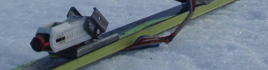
152 Figure 69 - Prototype in downhill mode Figure 70 - Prototype in touring mode 134
153 Chapter 8 Testing and Evaluation 8.1 Introduction With a working prototype of the binding, testing and evaluation was undertaken to determine the success of the design. This included bench-top testing, calibration, field trials, and evaluation against design specifications and other products. The methods and results of these tests are presented in this chapter. 8.2 Bench-top testing Bench-top testing was carried out in order to calibrate the release settings and to compare the binding with the general requirements of ISO 13992:2006, Alpine touring ski bindings Requirements and test methods. This testing also helped understand the behaviour of the release mechanisms and contributed towards final evaluation of the prototype design Test requirements Loading Rate The tests were performed quasi-statically, ensuring that the following indicative values of the torque gradient were respected: torsion release: dm z /dt 50 N m/s; forward bending release: dm y /dt 220 N m/s (ISO 13992:2006, Alpine touring ski bindings: requirements and test methods). Accuracy of Measurement In order to meet the standard of ISO 13992:2006, Alpine touring ski bindings: requirements and test methods, the measurement error of the release value in torsion was required to be 135
154 smaller than ± 2% for values 50 N m and ± 1 N m for values < 50 N m. The measurement error of the release value in forward bending was required to be smaller than ± 2% for values 200 N m and ± 4 N m for values < 200 N m. The test equipment was designed to allow application of pure moments, without any extraneous forces, during the entire release process Test setup Test Sole The test sole used was in accordance with ISO 9838:2008, Alpine and touring ski bindings: test soles for ski binding tests, and ISO 5355:2006, Alpine ski boots: requirements and test methods. This ensured the binding would interact in a normal manner with the boot by providing a standard sole shape. The toe and heel from the boot was removed and fixed to a steel structure to strengthen the test piece. Before testing, the sole was degreased, washed and dried. Test Ski For the release tests in the laboratory, the bindings were mounted on whole skis which represented the market and were readily available. These were K2 Gyrator skis, 187 cm in length. (a) (b) M z M y F 2x F 1x Figure 71 Setup of test rig for (a) sideways twisting and (b) forwards bending release 136

155 Test Method Both bindings were mounted on the set of test skis. Method A of ISO 13992:2006, Alpine touring ski bindings: requirements and test methods, was used, with the ski rigidly connected to the test frame and the torque M z or M y progressively applied to the sole until the binding released. Figure 69 shows a schematic of this method with the applied forces and corresponding moments displayed. In this case the test frame was a vertical steel beam in the mechanical engineering laboratory of the University of Canterbury. The test sole was then inserted in the binding along with the weight bar and load cell used to apply and measure the respective forces as shown in Figure 70. Weights were applied to the weight bar until release was obtained. This weight was then measured and converted into the release torque about the centre of origin of the binding, as required by Figure 72 Applying load to test the release torque of the binding 137

, a two-channel amplifier, 60 kg single point load cell transducer, digital multimeter, and a digital")
156 ISO 13992:2006, Alpine touring ski bindings: requirements and test methods. This method provided a reliable and repeatable process of measuring the release torque of the bindings. This was done for both forwards bending and sideways twisting release. The image in Figure 70 shows this method being applied for forwards bending release. Sideways release was obtained by unbolting the weight bar from the test sole, and reattaching it at 90 degrees. The measuring equipment needed for the test included digital weigh scales (as shown in Figure 71), a two-channel amplifier, 60 kg single point load cell transducer, digital multimeter, and a digital oscilloscope (as shown in Figure 72). With the load cell attached to the end of the weight bar, the force required to release the bindings was transmitted through it to the binding. This signal was then amplified and sent to both the digital multimeter and the oscilloscope. The multimeter was used to calculate the conversion from voltage reading to force, while the oscilloscope was used to gain a force Figure 73 Test setup in the laboratory 138


157 verse time plot of the release. This helped calibrate the binding as well as understand the nature of the release mechanisms. Figure 74 - Measurement equipment for bench top testing Testing results Results from testing helped identify several issues with the design as well as understand how the prototype functioned. Testing had two specific objectives of calibrating the release force and plotting this force against time. The results from both tests are explained in the following sub-sections Calibration Calibration was an essential part of the bench-top testing. Both the toe and heel pieces for each binding were calibrated for a release value range of 3 to 15. Using the method described in Section 8.2.2, Test setup, the required release forces were applied to the binding. The release spring was then adjusted until release was achieved quasi-statically. The adjustment screw was then measured in length from its interference with the 139
158 housing. This specific measurement of the screw position allowed the release setting to be repeated and hence calibrated. The angular adjustment of the screw between release values was also recorded. This, along with the pitch of the screw thread, was compared with the position measurement to ensure accuracy of the calibration. The plot below in Figure 73 shows this screw position against the release value for both toe pieces. Both Figure 75 Release values plotted against spring compression bindings show a similar profile for this curve. This curve, if further detail in calibrating was required, could be used to produce the adjustment scale for the release mechanism. This scale is included on all bindings and allows the user to easily adjust the release setting to a particular value within the range. The difference in screw position between the two bindings is due to the screws and housings interfacing at slightly different points on the binding. This therefore caused the measurements to be approximately 1 mm apart for each release value. This discrepancy did not in any way effect the performance of the release mechanism Release force curves After the calibration of the binding was completed, the release mechanism could be further understood by measuring the force required to release the boot from the binding over time. This was done using the same method as calibration, with the exception of applying a pre-determined force. Instead, the load bar was pulled directly downwards at 140

159 a relatively constant velocity. This was done to simulate the slow release method of an injury causing fall such as valgus-external rotation (see Section 3.3.4, Safety and injuries). The digital oscilloscope measured this force against time and was freezeframed to capture the resulting plot. Since the export function of the oscilloscope was not operational, photos were taken to transfer the information from this testing. The plot in Figure 74 shows this for the toe piece set on a release value of 11. Figure 76 Force verse time plot of the toe piece release mechanism This shows how the mechanism resists the applied force until it reaches 87 N (this relates to the peak of 154 mv) in a repeatable fashion. Up until the point of release, the shape of the curve is relatively smooth. After this point of release, the shape of the curve is not as consistent. This roughness in the mechanism could be felt by the user of the test rig when applying the release force. It is understood that this effect is due to the mechanism requiring use of two release springs rather than only one. 141
160 8.3 Field testing Field testing was required by ISO 13992:2006, Alpine touring ski bindings: requirements and test methods, as a complimentary test to bench-top trials. This was required to be carried out once the binding had passed all required bench-top tests. Since the binding did not meet all requirements from the standard, it was decided that the field tests would not be carried out. They are summarised below however as they were considered as a method of evaluation. Test summary The binding is to be mounted on an all-mountain ski suitable for the intended use of the binding. The snow conditions to be tested include hard to icy snow, piste (on which moderately unfavourable conditions prevail), and soft snow with moderate to high clearing resistance. The bindings must be tested by four skiers in winter conditions, on several difficult runs with a total vertical drop of at least 5000 m. Unwanted release, boot-to-ski connection, stepping into the binding, manual release and touring function are all then evaluated to provide the binding with a total performance score. This can then be used as another method of evaluating the binding s success. 8.4 Prototype evaluation Following on from testing the prototype, the design was evaluated against the initial design specification and existing binding products. The results from these evaluations are as follows and give an insight as to what can be improved if this project were to continue in the future Evaluation against design specification This evaluation was simply a matter of answering whether the binding met the various design requirements. The results of this evaluation are detailed in Appendix I, Evaluation against product design specification. Although the prototype met many of the design requirements set out in the initial stages of the project, there were still several which it did not meet. Most importantly, it failed to meet the required standards of AT bindings. While this was the only demand of the design requirement specification which 142
161 the binding did not meet, it was also not so crucial since this was only a first stage prototype. Other points it failed to meet included low weight, being interchangeable between ski sets, and smooth and reliable release. While these were important to the function of the binding, they are also reasonably easy faults to improve on without significantly altering the design. The design did however meet a large number of requirements. This included being low profile, compatible with skis widths 80 mm 150 mm, allowing the ski to flex underfoot, fully adjustable, releasable in forwards leaning and twisting situations, operable with a ski pole and provided a variation to what already existed Comparison with existing products Compared with other products, the usability of the binding is certainly a downfall. Switching modes proved to be too precise and ultimately required too much time and effort. This would need to be improved to entice possible customers. Another point which ranks quite low compared with the competition is the binding s appearance. Again, this would require significant improvement before it better than, or at least on par with, its competitors. The safety mechanisms of the binding also need to be addressed. The binding immediately ranks higher than any direct competitors in terms of binding height however. Although this aspect of the project was clearly successful, there are also other features which the binding ranks higher than other competitor products. For example, the binding is able to fit all sizes of adult ski boot, unlike most current AT binding designs which are sold in different sizes. The advantages that this design presents against competitors suggests that there is potential for the project to continue on in the future. 143
162 Chapter 9 Conclusions and Recommendations 9.1 Future improvements Ski bindings, skis and skiing styles will always keep evolving. This constant development of skiing will continue to drive competition between various ski equipment manufacturers. In the case of this project, the future development of the binding would involve assessing whether the design has serious market potential or whether another round of conceptual design would be necessary. The following sub-sections present a number of recommendations to how the current design of the binding could be improved Usability The usability of a ski binding can make or break its success in the market. If it is easy to use, people will generally like to use it. Therefore the usability of the binding is crucial and needs to be addressed with future improvements. The following list details several improvements which could assist in this way. 1. Switching between touring and downhill mode could be improved significantly. The current system employed in the prototype works well in principle but needs to be fine-tuned to work well in practice. 2. Introducing a binding which was interchangeable between ski sets would surely change the way bindings are designed. This simple feature of product usability could allow a user to make full use of the bindings on multiple pairs of skis. 3. Allowing the whole binding to move fore and aft on the ski would also provide a huge advantage to the user. A feature such as this would certainly make the product more user-friendly. 144
163 4. Although the mounting screws were positioned so they were easily reached, the binding could still be made easier to mount. This would obviously include the design and production of a mounting jig, but would also include re-design of the base plates and surrounding parts to allow a more intuitive mounting arrangement. 5. Using two release springs for the toe would be off-putting for a lot of users. One release spring for each mechanism should be all that is needed. Several of these points, such as the switching of modes, would require a reasonable amount of design work to implement. Although the basis of the binding s usability is solid, some of the principle features may need to be re-designed completely. This would be a lengthy process but several of the functional design features could also benefit from this work Technical function Possible improvements to the technical function of the binding were largely identified through considering the points made in Section 7.5.1, Prototype problems. Improvements to solve these problems, along with some other possible improvements, are stated below. 1. In order to meet ISO 13992:2006, Alpine touring ski bindings: requirements and test methods, the binding would have to include safety release during tour mode something that is not currently satisfied. 2. The connection between the toe stub and toe piece could be strengthened significantly in the upwards direction. This type of force is most commonly experienced during a backwards leaning fall. 3. The toe piece release mechanism could be smoothed by possibly negating the need for both release springs. The toe stub form could also be modified to give a more precise movement. 4. The spring used to assist the changing of modes could be strengthened to provide a more reliable mechanism. This could easily be done by re-designing this component. 5. Another improvement which could add value to the design would be allowing release in tour mode at a lower torque than for downhill. This would be desirable 145
164 for all touring users who venture into the backcountry, though it could be a difficult feature to implement. 6. The AFD could be strengthened in the downwards direction by adding teeth to the bottom of the wedges and the corresponding surfaces on the toe base. This would stop the AFD assembly from slipping in its place. 7. Add teeth to inside of AFD wedges 8. Try greater vertical collapse of heel piece as it closes on boot by arranging pivot points These recommendations could easily be used for further work on the binding design. Many of these suggestions would be simpler to implement than the previous points on usability. In conclusion, although there is a lot more room for improvement on the current design, it is believed that this project would be worth continuing with. 9.2 Concluding statements The objective of this thesis was to develop a low profile AT binding for high performance users. While the resulting prototype is certainly low profile, it still requires a significant amount of work to be done before it can be used by this type of aggressive backcountry user. The process undertaken to reach this point has included a well-rounded investigation into skiing and ski bindings, as well as a significant effort into the actual design and manufacture of the prototype. This design process covered the formation of design requirements, generation of a multitude of innovative concepts, and the detailed design with a focus on design for manufacture. Production of the prototype within the University of Canterbury was followed by testing and evaluation of the binding design. All members of the team are satisfied with the success of the project and are hoping for it continue in the future. 146
165 References Ashby, M. F. (1992). Materials selection in mechanical design. Oxford: Pergamon Press Ltd. Baxter, M. R. (1995). Product design. London: Chapman & Hall. Bowden, F. P. & Hughes, T. P. (1939). The mechanism of sliding on ice and snow. Proc. R. Soc., Ser. A, Vol. 172, pp Buxton, B. (2007). Sketching user experiences. Boston: Elsevier Science Ltd. Campbell, S. (2004). About interface. Ski, Vol. 69 (1), pp Cohn, J. (2003). Binding systems: the quest for the perfect arc. Skiing, Vol. 56 (2), pp Cross, N. (1989). Engineering design methods: strategies for product design. Chichester: John Wiley & Sons Ltd. Crow, K. A. (2001). New product development solutions. Retrieved from Dawson, L. (2007). Backcountry skiing binding flex tests. Retrieved from Dolov, M. A. (1967). Snow deformation in the case of large impact loads. Nal-chik, USSR Vysokogornyi Geofizicheskii Inst., Trudy, No. 9, pp Flower, R. (1976). The story of skiing and other winter sports. London: Angus & Robertson (U.K.) Ltd. Gray, D. M. & Male, D. H. (1981). Handbook of snow. Ontario: Pergamon Press. 147
166 Hay, J. G. (1985). The biomechanics of sports techniques (3rd ed.). New Jersey: Prentice- Hall, Inc. Howe, J. (2001). The new skiing mechanics. Waterford: McIntire Publishing. Howe, S. (1994). Touring, trekking. Backpacker, Vol. 22 (9). ISO (1990). Touring ski-boots for adults: interface with ski binding. ISO 9523:1990 (E). Geneva: International Organisation for Standarisation. ISO (1991). Alpine ski bindings: lateral release under impact loading test method.iso 9465:1991 (E). Geneva: International Organisation for Standarisation. ISO (1997). Ski bindings: vocabulary. ISO 8614:1997 (E/F). Geneva: International Organisation for Standarisation. ISO (2003). Skis: vocabulary. ISO 6289:2003 (E/F). Geneva: International Organisation for Standarisation. ISO (2004). Alpine ski bindings: selection of release torque values. ISO 8061:2004 (E). Geneva: International Organisation for Standarisation. ISO (2004). Alpine ski bindings: retention devices requirements and test methods. ISO 11087:2004 (E). Geneva: International Organisation for Standarisation. ISO (2005). Touring ski boots for adults: interface with touring ski bindings requirements and test methods. ISO 9523:2005 (E). Geneva: International Organisation for Standarisation. ISO (2006). Alpine ski bindings: requirements and test methods. ISO 9462:2006 (E). Geneva: International Organisation for Standarisation. ISO (2006). Alpine ski boots: requirements and test methods. ISO 5355:2006 (E). Geneva: International Organisation for Standarisation. ISO (2006). Alpine touring ski bindings: requirements and test methods. ISO 13992:2006 (E). Geneva: International Organisation for Standarisation. ISO (2008). Alpine and touring ski bindings: test soles for ski binding tests. ISO 9838:2008 (E). Geneva: International Organisation for Standarisation. Kerasote, T. (1998). All terrain skiing. Sports afield, Vol. 221 (1), pp
167 Lawson, B. (1997). How designers think. Oxford: The Architectural Press. Lind, D. & Sanders, S. P. (1996). The physics of skiing: skiing at the triple point. New York: Springer-Verlag Inc. Lund, M. (1996). A short history of alpine skiing. Skiing Heritage, Vol. 8 (1). Megroz, G. (2005). Bindings. Skiing, Vol. 58 (2), pp NASA (1995). Man-system integration standards. NASA STD Houston: National Aeronautics and Space Administration. Natri, A., Beynnon, B. D., Ettlinger, C. F., Johnson, R. J. & Shealy, J. E. (1999). Alpine ski bindings and injuries. Sports Med, Vol. 28 (1), pp Pascolo, P. B. (2004). Biomechanics and sports: Proceedings of the XI winter universidads New York: Springer-Verlag Wien. Pizlo, Z. (2008). 3D shape: its unique place in visual perception. Cambridge, MIT Press. Seiler, S. (2005) Masters athlete physiology and performance. Efficiency, economy and endurance performance. Retrieved from Schaffer, J. P., Saxena, A., Antolovich, S. D., Sanders, T. H., Warner, S. B. (1999). The science and design of engineering materials. Boston: WCB/McGraw Hill. Shealy, J. E., Geyer, L. H. & Hayden, R. (1974). Epidemiology of ski injuries: effect of method of skill acquisition and release binding accident rates. Hum factors, Vol. 16 (5), pp Starkey, C. V. (1992). Engineering design decisions. London: Edward Arnold. Subic, A. J. & Haake, S. J. (2000). The engineering of sport: research, development and innovation. Oxford: Blackwell Science Ltd. Thompson, R. (2007). Manufacturing processes for design professionals. New York: Thames & Hudson Inc. Todd, R. H., Allen, D. K. & Alting, L. (1994). Manufacturing processes reference guide. New York: Industrial Press Inc. 149
168 Ujihashi, S. & Haake, S. J. (2002). The engineering of sport 4. Oxford: Blackwell Science Ltd. Utterback, J. M., Vedin, B. A., Alvarez, E., Ekman, S., Sanderson, S. W., Tether, B. & Verganti, R. (2006). Design inspired innovation. World Scientific Publishing Company. Yaw, L. (2004). Uphill downhill gear: bindings. Skiing Vol. 56 (7), pp
169 Appendix A: Product design specification Demand: Wish: Weight: Requirements: Source: Modified: A feature which must be included in the design to meet specifications (D) A desirable feature that will increase the products market value if included (W) The weighting of a design requirement relates to its importance to the overall design and is defined as high (H), medium (M) or low (L) Features of the design split into sub categories. Requirements can assist in the conceptual and developmental design stages to ensure the product is on the right track The person who contributed to the particular requirement (Tyrone Low, TL; Alex Herbert, AH) Any modifications to the PDS must be recorded D/W Wt. Requirements Source Modified D W W D W W H H H M Geometry Max. height of boot sole from ski 20 mm Max. height of boot sole from ski 10 mm Max. width of base plate 76 mm Min. width of base plate 56 mm Compatible with ski widths 80 mm 150 mm Appropriate spacing of mounting points AH TL TL TL TL TL AH 13/5 AH 13/5 TL 13/6 D D D W W W W W W W W W H M M L M M H M M Function Include a pivot for touring mode Allows the ski to flex with boot in binding Boot-to-ski stiff and rigid until point of release Low weight and inertia Low lift weight for touring Preferably mechanical release mechanism with very low maintenance Range of pivot of at least 90 2 or more appropriate climb height settings Interchangeable between multiple ski sets Adjustments to match ski boot of any size or shape Fore/aft position on ski is adjustable Crampon compatible TL TL TL TL TL TL TL TL TL TL TL TL AH 13/5 TL 13/5 AH 17/3 AH 17/3 TL 25/5 AH 17/3 TL 12/6 151
170 W H Forces Design accommodates at least 90kg aggressive skier TL AH 17/3 W H Energy Normal operation between -35 C and 15 C TL W W H H Material Life expectancy of 10 years Will not corrode TL TL D Control and information No instruction or training needed to use TL D D W W W M H H Safety No sharp edges Release in forwards lean and twisting situations Release in all situations Smooth and reliable release Large release range of DIN TL TL TL TL TL TL 25/6 TL 13/5 D D D W W H H Quality Meets appropriate standards for ski bindings Release mechanism complies with DIN Adjustable release Inspected after manufacturing for any flaws Design life of 10 years TL TL TL TL TL AH 13/5 AH 13/5 TL 13/5 W W W W D M M M M Manufacturing Fixings can be purchased off the shelf Able to be mounted to ski by ski technician in normal time Able to be manufactured locally at reasonable cost Release able to be calibrated after manufacture Prototype to be ready by 1 September 2008 TL TL TL TL TL TL 13/5 D Economic Market for the binding exists TL W W W W W W M M H H M H Ergonomic No instructions needed for use Warning needed for use Can be used by a fit 15 year old of normal ability Easily operable with a ski pole Modes able to be changed without exiting binding Reassembly not needed after release during fall TL TL TL TL TL TL AH 13/5 TL 13/5 TL 25/5 W H Ecological Non-toxic materials used TL W W W W H L H H Aesthetic Pleasant Appearance Streamlined for movement in soft snow Module appeals to target group Binding looks safe and reliable TL TL TL TL TL 13/5 W W W W H M H M Performance Binding provides variation to what already exists Provides an additional features for the user No compromise in downhill performance No compromise in touring performance TL TL TL TL TL 25/5 TL 25/5 152
171 B: Evaluation of master concepts Pure Pivot Virtual Pivot Flexi Pivot Sliding Pivot Criteria (Weight, Value) Wt. Val. Wt. Val. Val. Wt. Val. Val. Wt. Val. Val. Wt. Val. Touring Features Appropriate pivot style Angular pivot range Usability of features Torsional stiffness Touring efficiency Appropriate heel lift Touring return tension Crampon compatible Downhill Features Sufficient space for release Appropriate release modes Usability of features Low and centred inertia Rigid in downhill mode Low profile to ski Smooth AFD function Binding flexes with ski General features Positional adjustment Boot length adjustment Toe height adjustment Toe width adjustment Release adjustment Interchangeable between skis Compact functionality Operable with a ski pole Mode change without exit Overall Aesthetically pleasing Minimal ice build-up Simple under foot design Sufficient strength Snow flow around binding Manufacturing cost Easy to mount Release calibration Low weight Variation from competition / / / /
172 C: Master concept sketches 154
173 155
174 156
175 157
176 158
177 159
178 160
179 161
180 162
181 163
182 164
183 165
184 166
185 167
186 168
187 169
188 D: Material properties Polymers Material Tensile strength (MPa) Tensile modulus (GPa) Flexural strength (MPa) Impact strength (J/m) Hardness (Rockwell) ABS R103 POM R120 Nylon R119 PET R120 Metals Material Temper Tensile strength (MPa) Yield strength (MPa) Young s modulus (GPa) Hardness (HB) 7075 Alloy O T6, T T73, T735x AISI 304 SS AISI 316 SS Properties taken from Schaffer et al. (1999). 170
189 E: Assembly drawings 171
190 172
191 173
192 174
193 175
194 176
195 F: Engineering drawings 177
196 178
197 179
198 180
199 181
200 182
201 183
202 184
203 185
204 186
205 187
206 188
207 189
208 190
209 191
210 192
211 193
212 194
213 195
214 196
215 197
216 198
217 199
218 200
219 201
220 202
221 203
222 204
223 205
224 206
225 207
226 208

227 G: Rendered drawing 209


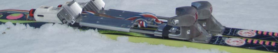

228 H: Prototype images 210


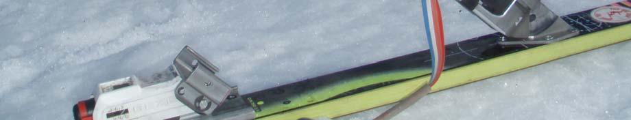

229 211


230 212
How does nordic skiing differ from alpine skiing?
 1 How does nordic skiing differ from alpine skiing? nordic Skis are design for both uphill and downhill travel. Skis need to both grip and glide. Bindings are free heel to allow for a natural stride. Muscled
Kinematics errors leading to Ski Injuries (2015) Haleh Dadgostar MD Sports Medicine Specialist Iran University of Medical Sciences
 Haleh Dadgostar MD Sports Medicine Specialist Iran University of Medical Sciences") Kinematics errors leading to Ski Injuries (2015) Haleh Dadgostar MD Sports Medicine Specialist Iran University of Medical Sciences Alpine Ski Practice of skiing : 5000 years ago when early hunters and
Kinematics errors leading to Ski Injuries (2015) Haleh Dadgostar MD Sports Medicine Specialist Iran University of Medical Sciences Alpine Ski Practice of skiing : 5000 years ago when early hunters and
THE RIGHT TURN 100% ROSSIGNOL, FROM THE SOLE OF THE BOOT TO TIP OF THE SKI PLATE BINDINGS BOOTS SKIS. TURNAMIC The new global standard.
 p.1 100% ROSSIGNOL, FROM THE SOLE OF THE BOOT TO TIP OF THE SKI Designed as a fully comprehensive, ski-boot-binding system, TURNAMIC integrates each component to provide a simple, adaptable, and dynamic
Safety Alubar System 2016 / 17
 Safety Alubar System 2016 / 17 Fritschi AG Swiss Bindings Hauptstrasse 9 CH-3713 Reichenbach Phone +41 33 672 14 15 Fax +41 33 672 14 10 info@fritschi.ch www.fritschi.ch Diamir Fritschi Swiss Swiss Innovation
Skier Evaluation Form
 Skier Evaluation Form Instructor Alignment Stance Discipline Reference Alignments Terrain Green Blue Black Off-Piste : Side Slip w/ Stop Wedge Change-Ups Hockey Stop Hops in a Straight Run Side Slips with
SYMBIOZ M. 50 > 120 Kg 110 > 260 lbs. 70 > 140 Kg 150 > 300 lbs. 60 > 120 Kg 130 > 260 lbs > 120 Kg 110 > 260 lbs. 40 > 100 Kg 90 > 220 lbs
 All snowshoes of this classic range have been designed and developed for each type of consumer to find the pair corresponding to their specific use. They are made entirely in France with TSL in total control
Custom Skis Handmade with Swiss Precision
 Custom Skis Handmade with Swiss Precision A dream comes true! After three years in the making, a custom made ski from the Swiss Alps has arrived. Core Skis Core Skis embody top quality, custom made skis
GUIDE BINDING USER MANUAL
 GUIDE BINDING USER MANUAL This user manual must be given to the final customer Version 2014.04.04_v5 1 P a g e 4 3 1 2 1- Toe pin 2- Crampon slot 3- Locker 4- Leash 2 P a g e 13 14 5 6 10 11 7 8 12 5-
Coaching Principles. STEPS IN TEACHING A DRILL 1. Introduce 2. Demonstrate 3. Explain 4. Organize 5. Execute 6. Correct 7. Practice GENERAL PRINCIPLES
 Alpine Skiing Drill Book Updated August 2008 STEPS IN TEACHING A DRILL 1. Introduce 2. Demonstrate 3. Explain 4. Organize 5. Execute 6. Correct 7. Practice GENERAL PRINCIPLES Coaching Principles Drills
SKIING AND SNOWBOARDING Alpine free ski with performance on all terrain
 1 of 5 level: 5 credit: 15 planned review date: June 2009 sub-field: purpose: Snowsport People credited with this unit standard are able to alpine ski on all at a snowsport area through changing snow conditions
The brand identity with the new Fritschi logo represents the technical evolution packaged in a modern, attractive design.
 New brand identity and new generation of pin bindings With the legendary Diamir Titanal bindings, Fritschi gave new impetus to the touring world with a lot of innovation. The efforts then and now - are
Unit: Skiing and Snowshoeing Skiing
 1 Unit: Skiing and Snowshoeing Skiing Although the word "skiing" was originally used as a generic term for traveling through the snow on two long boards, the sport has evolved dramatically to include many
2009 G3 Genuine Guide Gear Rev -
 1. Important warnings and instructions 1.1. Important Warnings The release setting requires a specialized understanding of multiple factors. Adjustments to release settings should only be made by an authorized
Part 2: Specific Skills
 1/12 Part 1: The AMGA Ski Standard Goals The following descriptions are intended to help both candidates better self-assess their skiing skills as well as aid instructors/examiners in assessing skiing
MODERN ARCHERY Compound Bow
 MODERN ARCHERY Now, into chapter four, the newest bow in this series, the Compound Bow. Again, this is a development of the Composite Bow, but what a significant development it is. The changes compared
Beginner Skier Progression -Class Levels One and Two Never-ever skiers to skiers making advanced wedge turns
 Beginner Skier Progression -Class Levels One and Two Never-ever skiers to skiers making advanced wedge turns This is an in depth progression which would be more suitable for students who are not particularly
DECREE TECH FEATURES FELT LONG, LOW, SLACK GEOMETRY
 TECH FEATURES FELT DECREE In October 2015, Felt Bicycles introduced an entirely new trail bike into its family: the Decree. Through many iterations of development and design, plus demanding testing and
Fundamental Mechanics of Alpine Skiing Across Adaptive Disciplines. Produced by PSIA-AASI, in cooperation with Disabled Sports USA.
 Fundamental Mechanics of Alpine Skiing Across Adaptive Disciplines Produced by PSIA-AASI, in cooperation with Disabled Sports USA. Balance & Stance - Beginner/Novice Zone Control the relationship of the
A. TO PREPARE THE MACHINE FOR USE.
 INSTRUCTION MANUAL FOR THE ML120 STRINGING MACHINE. CONTENTS: A. TO PREPARE THE MACHINE FOR USE. 1. The assembly of frame with console and tooltray. 2. Fixing the lever of the tension unit. 3. Putting
Technical Briefing Note
 Technical Briefing Note Subject Date Issued Revision Glossary of Terms 14th Nov 2017 Rev 3 The purpose of this Technical Briefing Note is to provide a glossary of terms commonly used in fall injury prevention
The Mechanics of Modern BREASTSTROKE Swimming Dr Ralph Richards
 The Mechanics of Modern BREASTSTROKE Swimming Dr Ralph Richards Breaststroke is the least efficient of the four competition strokes because a large amount of water resistance is created due to body position
For over 100 years Rossignol has been the benchmark in winter sports, making skiing and riding easier, more inspiring, and more fun.
 For over 100 years Rossignol has been the benchmark in winter sports, making skiing and riding easier, more inspiring, and more fun. From competitive athletes to cautious first-timers, Rossignol s athlete-driven,
Guided Uphill Arc Blue Groomed. Carved Uphill Arc Blue Groomed. Skate on Flat Terrain Green Groomed. Vertical Side Slip Blue Groomed
 The 3 task matrices describe skiing with specific application of different skill blends. Mastery of the tasks in the 3 matrices can help create versatile skiing. All tasks require skilled simultaneous
READING, EDITING AND PRESENTING THE ALPINE CERTIFICATION GUIDE IS LIKE THIS IMAGE BECAUSE..
 READING, EDITING AND PRESENTING THE ALPINE CERTIFICATION GUIDE IS LIKE THIS IMAGE BECAUSE.. CERTIFICATION KEY UPDATES 2016-2017 Why the updates? Skiing updates Level 2 teaching Level 1 Examiner assessments
Northern Rocky Mountain Division
 Northern Rocky Mountain Division Adaptive Snowboard Level 1 Riding Requirements Riding Skills Work with your trainer(s) on the following riding demonstrations and tasks, any item listed may be used for
REVO Single Boot System Binding Installation Manual
 REVO Single Boot System Binding Installation Manual Revision Date: August 2016 REVO Sub-Z :Toe Clamp / Heel Release- Clamp REVO MAX: Toe Block / Silvretta Release REVO AIR :Toe Clamp/Heel Clamp REVO ST:
2005/2006 Snow Ski Technical Manual
 2005/2006 Snow Ski Technical Manual Revision: 041215X Contents Introduction by Dave Goode... 3 Attributes... 4 Model Specifications... 4 Snow Ski Terminology... 5 Binding Installation... 6 Binding Mounting
Structure (Down plane)
") By Lauren Russell Structure (Down plane) The body (toes, knees, hips, wrists and shoulders) is aligned parallel to the intended target line. The torso is tilted over the ball from the hips whilst maintaining
By Lauren Russell Structure (Down plane) The body (toes, knees, hips, wrists and shoulders) is aligned parallel to the intended target line. The torso is tilted over the ball from the hips whilst maintaining
Synchronised Swimming Skill Level 4
 1 2 3 4 5 6 7 8 9 10 11 Synchronised Swimming Skill Level 4 The must be an Advanced Name. Date Contents Pre requisite; PRE 1 Right or Left Flat Split on land PRE 2 Right or Left Leg Over Split on land
TEACHING METHODOLOGY SKIING
 TEACHING METHODOLOGY SKIING Fall 2017 National Office / Bureau National: 32 Ancolies St., SADL, Qc J0R 1B0 http://adaptivesnowsports.ca CADS TEACHING METHODOLOGY SKIING CADS Mission CADS provides opportunities
Mechanical Knee Prescription Guide
 Mechanical Knee Prescription Guide CONTENTS K1 LOCKING KNEE 1 K1 - K2 BALANCE KNEE OFM1 2 BALANCE KNEE OFM2 3 K2 BALANCE KNEE OM8 4 TOTAL KNEE 1900 5 K2 - K3 OP2 KNEE 6 OP4 KNEE 7 OP5 KNEE 8 OHP3 KNEE
Wave Comfort 2. Product Manual
 Wave Comfort 2 Product Manual Instructions The Wave Comfort 2 is designed to be maintenance free. The foot is water resistant; however, if the foot is submerged in water, the foot and foot shell should
Basic steps and spatial-temporal dimensions in the process of skills acquisition in alpine skiing
 Basic steps and spatial-temporal dimensions in the process of skills acquisition in alpine skiing Rado Pisot 1,2, Tomaž Šegula 2, Milan Žvan 2, 3, Blaž Lešnik 2,4 1 Institute for Kinesiology Research,
Classic cross country skiing 101
 Classic cross country skiing 101 Created by Lisa Wickerson for Trakkers Ski Club 2017 Contents Trail code Trail markers Putting on your skis Fitting and putting on ski poles Ski techniques Diagonal stride
PHASE 1 WIND STUDIES REPORT
 PHASE 1 WIND STUDIES REPORT ENVIRONMENTAL STUDIES AND PRELIMINARY DESIGN FOR A SUICIDE DETERRENT SYSTEM Contract 2006-B-17 24 MAY 2007 Golden Gate Bridge Highway and Transportation District Introduction
PSIA-RM Development Pathway - Alpine Skiing Standards
 Highlighted Skills PSIA-RM Development Pathway - Alpine Skiing Standards Fundamental Mechanics relative to the Skills Concept Pressure Control Rotational Control Edge Control Fore/Aft : Control the relationship
DISCOVER NEW OPTIONS THE NEW GENERATION X
 DISCOVER NEW OPTIONS THE NEW GENERATION X MULTIFUNCTIONAL ALL MOUNTAIN FRAME CONCEPT 3 VERSIONS: CARBON ALUMINIUM EMTB 3 WHEEL SIZES WITH TYRE WIDTH UP TO 3.00 IN 1 FRAME: TRAIL: 27.5 WHEELS TRACTION:
Rochester Nordic Ski Team Ski Skill Checklist
 Rochester Nordic Ski Team Ski Skill Checklist Home position Home position is a way to get people to feel the basic body position that is used in skate skiing. It s a unique stance that isn t used in other
RIPPLE TANK - with rippler & kit
 GENERAL DESCRIPTION: RIPPLE TANK - with rippler & kit Cat: SW3430-001 with illuminator, rippler & kit. The ripple tank is used to investigate wave motion in a shallow trough of water to understand how
EASILY SELECT THE RIGHT SKI
 EASILY SELECT THE RIGHT SKI 1 SNOW CONDITION 2 SKIER BODYWEIGHT UNIVERSAL CONDITIONS COMPACT SNOW HARD STICK CONDITIONS HARD STICK TO GRUN SNOW KLISTER CONDITIONS KLISTER In WorldCup there are three main
TECHNICAL PRODUCT INFORMATION
 2009-2010 TECHNICAL PRODUCT INFORMATION January 8, 2009 LEGEND SULTAN 85 The most versatile, high-performance, all-mountain ski we ve ever made, the Sultan 85 combines a wide, stable platform with deep
Full Batten 2 Systems
 Full Batten 2 Systems A range of fully integrated batten systems Almost all boats benefit from upgrading to a fully battened mainsail, but which benefits are most important to you, depends upon the type
AllPro Foot. Posterior Mount Product Manual
 AllPro Foot Posterior Mount Product Manual Instructions The AllPro PM foot system has been designed and manufactured for specific patient weights. Failure to follow the weight guidelines and/or overload
RJT. Pupil Task Cards: Throwing JUMP THROW RUN
 RJT s: Throwing RUN JUMP THROW s: Introduction Introduction to the s An important part of every child s cognitive development is to encourage them to explore new things and use self-guided learning to
Revisions to the Regulations for Agility Trials
 Revisions to the Regulations for Agility Trials Effective January 2, 2018 Equipment changes may be done prior to January 2, 2018, but must be completed by January 2, 2018 This insert is issued as a supplement
high tech ski & snowboard tuning tools
 research design made with HIGH TECH Born in 1975, the SKI MAN trade-mark has become internationally known thanks to his high-tech and high-quality products for ski and snowboard hand tuning. Our relationship
GUARDING OF FLOOR-TO-FLOOR WOOL PRESSES
 GUARDING OF FLOOR-TO-FLOOR WOOL PRESSES 1 NOTE The technical information in this book was current at the time of printing in 1984. While the guarding principles are still valid, the information does not
K2 Foot. Product Manual
 K2 Foot Product Manual Instructions The K2 is designed to be maintenance free. The foot is water resistant; however, if the foot is submerged in water, the foot and foot shell should be rinsed with fresh
Snowboard Certification Standards 2010
 American Association of Snowboard Instructors Snowboard Certification Standards 2010 National Standards: Level One, Level Two, Level Three Updated June 16, 2010 Table of Contents 1. Introduction 3 2. Movement
Constitution Instructions
 Constitution Instructions This kit will build a 1:48 scale hull for the USS Constitution frigate. The kit contains the following parts. 1/8 deck with laser etched deck lines 1/8 railing Ribs Center keel
Synchronised Swimming Skill Level 5
 1 2 3 4 5 6 7 8 9 10 11 Synchronised Swimming Skill Level 5 The must be an Advanced Name. Date Contents Pre requisite: PRE 1 Right Leg over Split on land PRE 2 Left Leg over Split on land 1. Barracuda
Writing Exam Feedback Fall Training Inspiring Lifelong Passion for the Mountain Experience
 Writing Exam Feedback Fall Training 2015 Inspiring Lifelong Passion for the Mountain Experience MISSION STATEMENT: Provide high quality educational resources and well defined standards to aid our members
The Portfolio Series has been added to the PSIA-C Curriculum to compliment the Portfolios.
 The Portfolio Series has been added to the PSIA-C Curriculum to compliment the Portfolios. See the AP 101, 202 & 303 Course Syllabuses for more information. Updated 10.4.10 INTRODUCTION TO PSIA CENTRALS
II.E. Airplane Flight Controls
 References: FAA-H-8083-3; FAA-8083-3-25 Objectives Key Elements Elements Schedule Equipment IP s Actions SP s Actions Completion Standards The student should develop knowledge of the elements related to
i NOTE: This installation manual contains important information related to system
 TRx Pivot Plus Manual Elevating Legrests (ELR) Installation and Set-Up Manual i NOTE: This installation manual contains important information related to system set-up and adjustments. Please forward to
Aeris Performance 2. Product Manual
 Aeris Performance 2 Product Manual Instructions The Aeris Performance 2 is designed to be maintenance free. The foot is water resistant; however, if the foot is submerged in water, the foot and foot shell
Foot System Prosthetist Manual
 Introduction Foot System Prosthetist Manual The Motionfoot is a hydraulic ankle, with a carbon fiber foot plate. It features; Very high ankle range of motion, up to 50. Smooth hydraulic transition from
THE FOUNDATION OF FIT
 THE FOUNDATION OF FIT 20 YEARS OF FIT INNOVATION HAVE LED US TO THE PERFECT BALANCE OF PRECISION AND COMFORT FOR EVERY ATHLETE AT EVERY LEVEL INSTANT FIT BOOTS FIT WELL IMMEDIATELY, WITH A LAST SHAPE REFINED
The learning of complex whole body activity (Downhill skiing) by simulation
 by simulation") The learning of complex whole body activity (Downhill skiing) by simulation Eddi Pianca Bachelor of Applied Science in Environmental Design(CCAE) Mechanical Engineering Certificate (ACT TAFE) A thesis
The learning of complex whole body activity (Downhill skiing) by simulation Eddi Pianca Bachelor of Applied Science in Environmental Design(CCAE) Mechanical Engineering Certificate (ACT TAFE) A thesis
Examination board s skiing criteria
 A personal view by Wayne Naylor, BASI member & maestro di sci at the Scuola Italiana Sci Folgarida Dimaro. In the original BASI News article (How to run a GCSE skiing video session) a number of other pages
HIGHLIGHTS. Quadruple Luff Panel Layout. Component Sleeve Construction
 The all-new EVO6 is the latest speed machine borne from the record-breaking RS:Racing programme. Brilliantly bright new livery is apparent but something more extraordinary hides beneath completely new
Model year 2014 USER MANUAL
 Model year 2014 USER MANUAL WARRANTY Terms and conditions BOS MTB offers warranty on its products on the following terms : BOS MTB guarantees to the original purchaser that the BOS product for which they
BIOMECHANICAL MOVEMENT
 SECTION PART 5 5 CHAPTER 12 13 CHAPTER 12: Biomechanical movement Practice questions - text book pages 169-172 1) For which of the following is the athlete s centre of mass most likely to lie outside of
Design Brief: Problem Statement:
 Design Brief: Problem Statement: The goal of this project is to design a safe, simple, and effective snowboard binding system for a triple amputee who lacks his right arm above the elbow and both legs
Kintrol Instructions for Use Product Number: VS4
 Kintrol Instructions for Use Product Number: VS4 Introduction The Kintrol foot/ankle combines hydraulics and fiberglass to provide K2 ambulators an exceptionally normal walking gait regardless of surface
Parts List. 7. Handlebars 8. Grips 9. Handlebar Stem 10. Front Brake 11. Front Wheel 12. Crank 13. Chain
 Woodworm Cruise Parts List 1. Free Wheel with Rear Hub 2. Fenders 3. Fender Stay 4. Quick Release 5. Saddle 6. Seat Post 7. Handlebars 8. Grips 9. Handlebar Stem 10. Front Brake 11. Front Wheel 12. Crank
The All New DIAMOND & DIAMOND BT
 The All New DIAMOND & DIAMOND BT. Specs The Diamond The Diamond BT Type Badminton Badminton & Tennis Pulling Method Constant Pull Constant Pull Tension Range 10 38 lbs 10 88 lbs Tension Increments 0.1
1B1 Meridium. Reclaim your way. Information for practitioners. Meridium Ottobock 1
 1B1 Meridium Reclaim your way. Information for practitioners Meridium Ottobock 1 Reclaim your way. With the development of the individualized Meridium prosthetic foot, Ottobock has incorporated the latest
Ice skate blade alignment mechanism
 Iowa State University Patents Iowa State University Research Foundation, Inc. 8-11-1992 Ice skate blade alignment mechanism Leon E. Girard Iowa State University Patrick E. Patterson Iowa State University
Final Assembly Instructions Bikes with Quill Stems
 Final Assembly Instructions Bikes with Quill Stems Thank you for buying your new bicycle from L.L.Bean. Read these instructions carefully before beginning the final assembly. Prior to shipping, our expert
With the new Patrik Formula V2 we are the first brand using WINGS on a production board a new era begins!
 With the new Patrik Formula V2 we are the first brand using WINGS on a production board a new era begins! Hiding the concept until the last possible day of registration we now announce the true worlds
Spring Locomotion Concepts. Roland Siegwart, Margarita Chli, Martin Rufli. ASL Autonomous Systems Lab. Autonomous Mobile Robots
 Spring 2016 Locomotion Concepts Locomotion Concepts 01.03.2016 1 Locomotion Concepts: Principles Found in Nature ASL Autonomous Systems Lab On ground Locomotion Concepts 01.03.2016 2 Locomotion Concepts
TOPIC OF THE MONTH FOR MARCH 2010 HOW CAN KICKERS AND PUNTERS INCREASE POWER?
 TOPIC OF THE MONTH FOR MARCH 2010 HOW CAN KICKERS AND PUNTERS INCREASE POWER? Imagine yourself as the quarterback for a winning Super Bowl team. You survived the season because your eyes read opponent
Final Assembly Instructions Bikes with Threaded Headsets
 Final Assembly Instructions Bikes with Threaded Headsets Thank you for buying your new bicycle from L.L.Bean. Read these instructions carefully before beginning the final assembly. Prior to shipping, our
Tail Roping 101. Teaching the finer aspects of rope handling. Jeff Cripps Central Division November 30, 2012
 Tail Roping 101 Teaching the finer aspects of rope handling Jeff Cripps Central Division November 30, 2012 Course Objective: Tail Roping 101 Develop better understanding of the skiing skills necessary
WONDERLAB: THE EQUINOR GALLERY. The science and maths behind the exhibits 30 MIN INFORMATION. Topic FORCES. Age
 WONDERLAB: THE EQUINOR GALLERY and maths s INFORMATION Age 7 11 11 14 Topic FORCES 30 MIN Location LEVEL 3, SCIENCE MUSEUM, LONDON What s the science? What more will you wonder? and maths s Wonderlab:
REFINE DEVELOP INTRODUCE
 ESSEX Ski Racing Training Criteria This document aims to set out the criteria that athletes are encouraged to achieve in order to progress through each of the training groups that make up the training
Deans, Directors, Heads of Schools and Departments and Research Institute Directors and Managers
 Working at Height 1. PURPOSE 1.1 To ensure that any work at height is carried out in accordance with the legal requirements and associated guidance. This includes the use of scaffolds, towers, ladders,
The Revolutionary Mach 1 has Evolved. Industry leading "out-of-the-box" fit is now available in two unique lasts with even more customized fit
 LV MV The Revolutionary Mach 1 has Evolved. Industry leading "out-of-the-box" fit is now available in two unique lasts with even more customized fit solutions. LINER TECHNOLOGY ANATOMICAL SHAPE PRECISE
SET OF EUROLEAGUE BACKSTOP UNITS (Reference PK120)
") SET OF EUROLEAGUE BACKSTOP UNITS (Reference PK120) DESCRIPTION The EUROLEAGUE backstop unit is mainly designed for multi-sports pavilions and installations where the highest-level basketball competitions
SET OF EUROLEAGUE BACKSTOP UNITS (Reference PK120) DESCRIPTION The EUROLEAGUE backstop unit is mainly designed for multi-sports pavilions and installations where the highest-level basketball competitions
2010 International Snow Science Workshop
 HOW TO TURN A KIDS BIKE INTO A BOMB TRAM FOR AVALANCHE CONTROL WORK David Immeker* Heavenly Mountain Resort Professional Ski Patrol, South Lake Tahoe, California ABSTRACT: Bomb trams have been used for
PERFORMANCE FREERIDE INSPIRED BY NATURE // DRIVEN BY THE ELEMENTS
 PERFORMANCE FREERIDE code V1 performance freeride range of use All Round Free Ride Performance 0 Medium Rocker and Medium Flex Progressive Outline with Amazing Control Intermediate to Advanced Free Riders
BOYLE S / CHARLES LAW APPARATUS - 1m long
 BOYLE S / CHARLES LAW APPARATUS - 1m long Cat: MF0340-101 (combination Boyle s and Charles without mercury) DESCRIPTION: The IEC Boyle's & Charles Law apparatus is a high quality instrument designed to
SASK-A-POLE OWNERS AND USERS MANUAL
 SASK-A-POLE OWNERS AND USERS MANUAL GENERAL INFORMATION The Saskatchewan Abilities Council s Sask-a-Pole accessibility and transfer aid is designed to help provide safe and easy access to chairs, beds,
Quattrocycle BV. Quattrocycle. User Manual. Last update February Quattrocycle BV Bremkant EJ Middelbeers. User Manual Quattrocycle 1
 Quattrocycle User Manual Last update February 2010 Quattrocycle BV Bremkant 6 5091 EJ Middelbeers User Manual Quattrocycle 1 Table of Contents Page Chapter 1: Introduction 3 Chapter 2: Instructions for
DM-RAPD (English) Dealer's Manual. ROAD MTB Trekking. City Touring/ Comfort Bike. SPD-SL Pedal DURA-ACE PD-R9100 ULTEGRA PD-R8000 SM-PD63
 Dealer's Manual. ROAD MTB Trekking. City Touring/ Comfort Bike. SPD-SL Pedal DURA-ACE PD-R9100 ULTEGRA PD-R8000 SM-PD63") (English) DM-RAPD001-01 Dealer's Manual ROAD MTB Trekking City Touring/ Comfort Bike URBAN SPORT E-BIKE SPD-SL Pedal DURA-ACE PD-R9100 ULTEGRA PD-R8000 SM-PD63 CONTENTS IMPORTANT NOTICE... 3 TO ENSURE
(English) DM-RAPD001-01 Dealer's Manual ROAD MTB Trekking City Touring/ Comfort Bike URBAN SPORT E-BIKE SPD-SL Pedal DURA-ACE PD-R9100 ULTEGRA PD-R8000 SM-PD63 CONTENTS IMPORTANT NOTICE... 3 TO ENSURE
READ ALL INSTRUCTIONS AND WARNINGS BEFORE USING THIS PRODUCT.
 Drywall Stills DS1830 Max Weight Capacity 225 Lb READ ALL INSTRUCTIONS AND WARNINGS BEFORE USING THIS PRODUCT. This manual provides important information on proper operation & maintenance. Every effort
Element DS. Product Manual
 Element DS Product Manual Instructions The Element DS is designed to be maintenance free. The foot is water resistant; however, if the foot is submerged in water, the foot and foot shell should be rinsed
Hoisting Equipment Cable puller & Accessories
 Yale hoists and trolleys are not ed for Cable puller model Yaletrac Pulling force 800-3200 It has a light weight, compact, high tensile aluminium alloy housing with a large flat bottom surface for increased
TEACHING MODEL ASSESS PRACTICE. Senior Geezer Focus - How? November, 2010 Cookie Hale P.J. Jones
 Senior Geezer Focus - How? The How is the methodology for coaching skiing; i.e. what you do with your time with your clients, how you communicate and coach skiing. The framework of this time spent coaching
CHAPTER IV FINITE ELEMENT ANALYSIS OF THE KNEE JOINT WITHOUT A MEDICAL IMPLANT
 39 CHAPTER IV FINITE ELEMENT ANALYSIS OF THE KNEE JOINT WITHOUT A MEDICAL IMPLANT 4.1 Modeling in Biomechanics The human body, apart of all its other functions is a mechanical mechanism and a structure,
Installation. Striping Kit for 42in and 50in Mowers Model No Installation Instructions. Removing the Mower Deck.
 Striping Kit for 42in and 50in Mowers Model No. 120 7905 Form No. 3368-794 Rev B Installation Instructions Installation Loose Parts Use the chart below to verify that all parts have been shipped. Procedure
F13.11 PARALLEL HINGES F13 PROJECT-OUT WINDOWS AND TOP HUNG WINDOWS
 F13 PROJECT-OUT WINDOWS AND TOP HUNG WINDOWS F13.11 01.06.2018 Waregemstraat 5-9870 Zulte - Belgium - T. +32 9 388 88 81 - F. +32 9 388 88 21 - commercial@sobinco.com - www.sobinco.com CONTENTS 1. General...F13.11.03
WalkOn product range. Dynamic Ankle-Foot Orthoses. Information for specialist dealers
 WalkOn product range Dynamic Ankle-Foot Orthoses Information for specialist dealers WalkOn Flex WalkOn WalkOn Trimable WalkOn Reaction WalkOn Reaction plus One range Many different applications The WalkOn
Mammut Special Features
 Mammut Special Features It s not only «Swiss quality» and one hundred percent dependability over a long life span which sets our harnesses apart. Our research engineers are continually developing innovative
MOTION FOOT MX. Manual
 MOTION FOOT MX Manual Real Technology - Real People CONTENTS Intruduction....4 Patient Selection....4 Foot Components....4 Special Precautions....5 Set-Up....6 Change Heel Height & Dorsi Flexion Range....
ABOUT THE TEACHING OF THROWING EVENTS
 ABOUT THE TEACHING OF THROWING EVENTS By Friedheld Endemann The following address provides a general outline of principles applied to learning practices in throwing events with recommended sequences for
QUATRO INTERNATIONAL 2010
 QUATRO INTERNATIONAL 2010 This new and unique 2010 Quatro line offers our latest in leading edge designs for ultimate performance. We have the freedom to offer a versatile set of boards that perform in
DESIGN BEHIND THE BIKE WHEELS
 DESIGN BEHIND THE BIKE WHEELS INTRODUCTION Far from being a simple, round, spinning object, the component parts of a wheel combine to affect weight, aerodynamics and the overall performance of a bike.
Kinterra Instructions for Use Product Number: ROM-00-XXXXX-XX
 Kinterra Instructions for Use Product Number: ROM-00-XXXXX-XX Introduction Patient Selection Assembly Alignment The Kinterra foot/ankle system combines hydraulics and carbon fiber, to provide low to moderate