Kennedy Bridge - Summary of Pier 6 Movement Records
|
|
|
- Suzan Jenkins
- 6 years ago
- Views:
Transcription
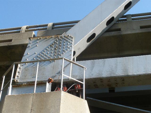
1 KENNEDY BRIDGE - SUMMARY OF PIER 6 MOVEMENT RECORDS TECHNICAL MEMORANDUM Kennedy Bridge - Summary of Pier 6 Movement Records PREPARED FOR: COPY TO: MnDOT Dale Thomas / CH2M HILL File PREPARED BY: DATE: May PROJECT NUMBER: Introduction John Hinman / CH2M HILL Bridge No. 9090, known as the Kennedy Bridge, carries U.S. Trunk Highway 2 across the Red River of the North between East Grand Forks, Minnesota and Grand Forks, North Dakota. This technical memorandum summarizes the records of the movements of Pier 6 of the Kennedy Bridge, as provided by the Minnesota Department of Transportation (MnDOT). It also summarizes the movement of Pier 6 relative to the steel truss superstructure. The location of Pier 6 is shown in Figure 1. An overview of the structure at Pier 6 is shown in Figure 2, with key components labelled. Figure 1 Location of Pier 6 KENNEDY-STUDY-SUMM-PIER-6-MVMT-MEMO 10 MAR 2014.DOCX 1
.")
2 KENNEDY BRIDGE - SUMMARY OF PIER 6 MOVEMENT RECORDS Figure 2 Structure and Pier 6 overview. Photo taken from ND side of river, looking southeast Movement Records Movement records available from MnDOT addresses of three separate movements (provided in the Appendices). These documents include various field measurements related to bearing, pier and ground movement: Log of Bearing Tilt. (See Appendix A) This document includes a log of the tilt of the bearings out of plumb that translates into top of pier movement. The measurements begin 10 September 1997 and extend through 24 October Adjustments to the rocker bases and the attachment of the bearings to the truss chord are noted along with the tilt measurements. MnDOT records identify the bearing movement as tilt. The value recorded is the horizontal offset of the top of the rocker from a plumb position, rather than an angular measurement. In addition to the rocker tilt measurements, this information contains distances from Bent 5 to Pier 6 recorded periodically between 23 September 2010 and 17 July 2012, and measurements of the bow in the wall that connects the north and south pier columns. Pier 6 Measurements. (See Appendix B) This consists of sketches of the existing configuration of Pier 6 from field measurements as of 16 July Measurements noted include tilt of the pier, location of rocker bases on the pier cap, sketch of the rocker bearing heel measurements, log of rocker bearing tilt through the July measurements, and photos. 2
3 KENNEDY BRIDGE - SUMMARY OF PIER 6 MOVEMENT RECORDS Slope Inclinometer Results. (See Appendix C) This document contains summaries of readings from two different slope inclinometers placed close to the south end of Pier 6. Readings cover the time periods from 3 June 2004 to 23 November 2009 (Inclinometer #1) and from 12 July 2010 through 2 May 2012 (Inclinometer #3). No readings were obtained from Inclinometer #2. Slope inclinometer readings provide incremental and cumulative movements in two axes. Readings extend to a depth of 60 feet below the existing ground surface. Movements not documented. All structure measurements document movement parallel to the centerline of the truss spans. No structure measurements address movement normal to the bridge. No measurements document vertical movement of Pier 6. Discussion of Pier Movement Initial Conditions The initial conditions are those at the date of construction. The design drawings do not identify the location of the Pier 6 rocker bearing with respect to the pier cap and the columns that make up Pier 6. MnDOT field observations and measurements (See Figure 6) indicate that the centers of the bearings were constructed 8 inches east (toward the river) of the center of Pier 6. Design drawings of the pier are reproduced in Figure 3. These drawings show a 5 foot wide pier cap centered above the pier columns and the pier footing. A 2 foot wide corbel is shown in the east side (towards the river); this corbel is believed to be provided to allow working room for jacking the truss and adjusting the bearings. Figure 3 Section Through Pier 6 3
4 KENNEDY BRIDGE - SUMMARY OF PIER 6 MOVEMENT RECORDS The rocker bearing is a fabricated steel element with a cylindrical bottom surface that bears on a 5 ¾ inch thick by 36 inch wide by 60 inch long plate. A series of four pintles attached to the plate engage holes in the bottom of the rocker, preventing the rocker from translating longitudinally or transversely relative to the plate. The rocker and plate drawings are reproduced in Figure 4. Figure 4 Rocker and Rocker Base Detail 4

5 KENNEDY BRIDGE - SUMMARY OF PIER 6 MOVEMENT RECORDS Bearing Movement Variability of Bearing Movement Records Examination of the records of the tilt of the north rocker bearing and the south rocker bearing at Pier 6 discloses that the tilt both increases and decreases between consecutive measurements. This can result from seasonal temperature variations that affect the length of the steel truss. A change in the temperature of the truss of 50 degrees F would result in a bearing movement of just over 1 inch. The air temperature was recorded with each movement record. As it takes time for the bridge to respond to changes in air temperature, however, it is necessary to consider not only the recorded temperature but also the season in which the measurement was made. This allows judgment of whether the bridge may have been consistently warm or consistently cool long enough to have responded to the air temperature. Variations in soil conditions that allow the pier to move both towards and away from the Red River may also affect the rocker tilt, although the slope inclinometer readings do not support movements of the soil mass away from the river. Given the variability of the readings, it is prudent to evaluate trends in rocker bearing tilt rather than relying on specific measurements. Trends may be more revealing than individual year to year measurements. First Bearing Movement Records The first movement record consists of measurement of tilt of the rocker bearings on 10 September A note is included stating that a rocker base had been moved 5 inches prior to This note is reproduced in Figure 5; the pertinent statement is highlighted in a red box. The direction of the move was not noted, but is assumed to be west (away from the river) and from field measurements of 2012 (Figure 5) this adjustment was made to both bearing plates. Figure 5 Note identifying rocker base move. A second bearing adjustment was recorded on 24 May This adjustment consisted of relocating the rocker base 6 inches. Based on the field measurements of 2012 (Figure 5), this is understood to refer only to the bearing plate for the south side of the bridge. In June of 1998, the south rocker bearing was tilted 7 ½ inches, with the top of the bearing west of the bottom of the bearing. After relocating the south bearing plate in 1999, the south rocker bearing remained tilted 3 ¾. This implies that the south side of the pier moved eastward relative to the truss approximately 2 1/4 between 1998 and Later Bearing Movement Records After the bearing plate relocation in 1999, the tilt of the south rocker bearing continued to increase. The tilt of the north rocker bearing remained essentially constant. 5
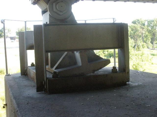
6 KENNEDY BRIDGE - SUMMARY OF PIER 6 MOVEMENT RECORDS The top of the south rocker bearing was relocated eastward 7 inches along the truss bottom chord in July of This resulted in a tilt of the rocker bearing of 1 3/8 inches, oriented with the top of the rocker west of the bottom of the rocker. This implies that the top of the pier moved relative to the steel truss approximately 2 inches between the May 2003 measurement and the July 2004 bearing adjustment. Latest Bearing Movement Records After the bearing relocation in July of 2004, the tilt of the south rocker bearing continued to increase. The tilt of the north rocker appears to have increased by a much smaller amount than did the tilt of the north rocker. The top of both the north rocker and the south rocker were moved eastward 7 inches along the truss chord in July of After this adjustment, the north rocker bearing had been adjusted a total of 7 inches and the south rocker bearing had been adjusted a total of 14 inches. After the July 2012 bearing adjustments, the south rocker bearing was essentially plumb. The north rocker bearing was tilted with the top of the bearing east of the bottom of the bearing. The south rocker bearing was tilted 6 ¾ inches to the west two months prior to the adjustment. The 7 inch adjustment brought the rocker close to plumb. The north rocker bearing was 3 inches to 4 inches out of plumb prior to the bearing adjustment, and was 1 3 / 8 inches out of plumb in the opposite direction after the bearing adjustment. Current Bearing Conditions The most recent bearing measurements were obtained in October of Those measurements show the north rocker bearing tilted 2 inches to the east and the south rocker bearing as plumb. These readings are within the operating range of the bearings. Figure 6 shows the field measurements locating the rocker bases on the pier cap. This diagram is copied from the MnDOT field notes. Figure 7 contains a photograph of the south rocker bearing, with the rocker base movement noted. 6

7 KENNEDY BRIDGE - SUMMARY OF PIER 6 MOVEMENT RECORDS Figure 6 Field Measurements of Pier Cap 7

8 KENNEDY BRIDGE - SUMMARY OF PIER 6 MOVEMENT RECORDS Figure 7 South Rocker Bearing, Pier 6, looking south along top of pier Rate of Bearing Movement The rate of movement of the rocker bearing is relatively uniform over the time in which MnDOT has been monitoring the movement of the bearing. Bearing adjustments have been made prior to 1997, in 1999, in 2004, and in Adjustment of the bearings has been infrequent and irregular, and there is insufficient information to determine a trend in bearing adjustments. Bearing Movement Diagram As an aid to interpreting the movement of the rockers and the rocker bases over time, a schematic diagram of the rockers, the rocker bases, and the center of Pier 6 relative to the end of the truss is presented in Figure 8. For each of five separate dates, an elevation diagram of each bearing is shown. A plan diagram of the two bearings is also shown. The information is presented as stick diagrams for clarity, as a scaled image of the structure would make it difficult to see the movement of the various elements. Elements are labelled in one elevation diagram and in one plan diagram. 8
9 KENNEDY BRIDGE - SUMMARY OF PIER 6 MOVEMENT RECORDS The first diagram shows the bridge as constructed. The rockers are plumb, and the workpoint at the end of the truss is centered over the rocker bases. The rocker bases are aligned with the center of bearing on the concrete pier. The center of the pier is aligned with the end of the truss. The second diagram represents the first bearing measurement, dated 9/10/1997. The rocker bases at both north and south bearings have been moved approximately 5 inches west on the top of the pier. The north rocker is inclined such that the top of the rocker is 3.63 inches west of the center of the rocker base. The south rocker is inclined with the top of the rocker 7.5 inches west of the center of the rocker base. The plan diagram shows the top of the pier twisted about a vertical axis. The third diagram represents the bearings on 5/24/1999. The rocker base at both north bearing is still 5 inches west on the top of the pier, but the south rocker base has been moved an additional 6 inches westward for a total movement of 11 inches. The north rocker is inclined such that the top of the rocker is 2.75 inches west of the center of the rocker base. The south rocker is inclined with the top of the rocker 3.75 inches west of the center of the rocker base. The plan diagram shows the top of the pier twisted further about a vertical axis. The fourth diagram represents the bearings on 7/7/2004. The rocker base at both north bearing is still 5 inches west on the top of the pier and the south rocker base is still 11 inches westward. The north rocker is inclined such that the top of the rocker is 3.25 inches west of the center of the rocker base. The south rocker has now been moved 7 inches along the bottom chord of the truss, and is inclined with the top of the rocker 1.38 inches west of the center of the rocker base. The plan diagram shows the top of the pier twisted further about a vertical axis. The last diagram in the series represents the bearings on 7/17/2012. The rocker base at both north bearing is still 5 inches west on the top of the pier and the south rocker base is still 11 inches westward. The north rocker has been moved 7 inches along the top chord, and is inclined such that the top of the rocker is 1.38 inches east of the center of the rocker base. The south rocker has now been moved an additional 7 inches along the bottom chord of the truss for a total of 14 inches, and is inclined with the top of the rocker 0.18 inches west of the center of the rocker base. The plan diagram shows the top of the pier twisted further about a vertical axis. 9
10 KENNEDY BRIDGE - SUMMARY OF PIER 6 MOVEMENT RECORDS Figure 8 Schematic of Bearing Movement over time 10
11 KENNEDY BRIDGE - SUMMARY OF PIER 6 MOVEMENT RECORDS Pier Displacement Records Bent 5 to Pier 6 Distance Periodic measurements were made of the distance between Bent 5 and Pier 6, beginning in September of 2010 and extending to October These measurements are reproduced in Appendix B. Locations of measurements are not indicated in the movement tables. The distance between Bent 5 and Pier 6 varies over time. The distance increases and decreases, as shown in the plot in Figure 9. This plot shows only the variation in distance, and is created by subtracting the initial value (the dimension on 9/23/2010) from the dimensions recorded by MnDOT. For the north measurements the value is subtracted; is subtracted from the center measurements, and is subtracted from south measurements. This technique accentuates the differences between measurements. Figure 9 Change in Distance between Bent 5 and Pier 6 A pertinent observation is that the distance between Bent 5 and Pier 6 both increases and decreases over time. There are some similarities in the movement curves; for example, the distance is a minimum for all three locations at the October 2011 measurement. A second pertinent observation is that the distance between Bent 5 and Pier 6 at the north side of the bridge is more than 3 feet larger than the corresponding distance at the south side of the bridge. This difference is shown in the figure Triangulation in Appendix B as the difference between Series 2 and Series 8. This is the opposite of what is expected based on tilting of the rockers and tilting of the pier. This may be accounted for by differences in location of the measurements, but without specific information regarding the location of the measurements the significance of this difference cannot be estimated. Bow in Pier 6 Wall The distortion of the center wall between the north and south columns of Pier 6 was measured periodically, beginning in September of 2010 and extending to October Measurements are assumed to be in inches, measured from a horizontal stringline parallel to the concrete wall. The distortion varies from 5.5 inches to 5.75 inches, and is observed to both increase and decrease. This variation in distortion of the center wall is not likely to be significant. Pier Tilt Detailed measurements of the tilt of Pier 6 were collected in July of Field notes for this measurement are contained in Appendix B. 11
12 KENNEDY BRIDGE - SUMMARY OF PIER 6 MOVEMENT RECORDS The south column at Pier 6 is tilted at a slope of ½ inch horizontal per foot vertical. The top of the pier is further west (away from the Red River) than is the footing. The north column at Pier 6 is tilted at a slope of 1 / 8 inch horizontal per foot vertical. The top of the pier is further west (away from the Red River) than is the footing. The pier height is 27 feet. Using the tilt as measured in July of 2012, the footing at the south of Pier 6 has moved approximately 13.5 inches relative to the top of the pier. The footing at the north of Pier 6 has moved approximately 3.4 inches relative to the top of the pier. The measurements of rocker bearing tilt, which are described above, indicate that the top of Pier 6 is moving eastward relative to the steel truss. The pier tilt indicates that the pier footing is moving eastward relative to the top if the pier. This means that the movement at the rocker bearing and the footing displacement calculated based on the pier tilt are in the same direction. Combining the rocker movement and the pier tilt, the footing under the north side of Pier 6 appears to have moved approximately 13.5 inches eastward relative to the steel truss above. The footing under the south side appears to have moved approximately 38.5 inches eastward relative to the steel truss above. Figure 10 contains a summary of the movement of Pier 6 at the south side of the pier relative to the steel truss. This figure includes the effect of adjustment of the rocker base and rocker bearing. Figure 10 Pier 6 Movement Ground Movement Records Three slope inclinometers were installed south of Pier 6. Records of the slope inclinometer results are shown in Appendix C. Slope inclinometer No. 1 was functional from June of 2004 through November of Slope inclinometer No. 3, installed adjacent to inclinometer No. 1, was functional from July 2010 and was still operational at the most recent reading in May of Slope inclinometer No. 2 was distressed by buoyant forces. No valid readings were obtained from this device. 12
13 KENNEDY BRIDGE - SUMMARY OF PIER 6 MOVEMENT RECORDS Inclinometers No. 1 and No. 3 provide readings in two orthogonal axes. The North Dakota Department of Transportation reports that the A Axis is oriented approximately 131 degrees from true north, which is approximately 45 degrees from the longitudinal axis of the bridge. Positive movements are toward the Red River. Both functioning inclinometers indicate a slip plane at a depth approximately 6 feet below ground surface and another slip plane approximately 27 feet below ground surface. The upper slip plane is above the pier footing, and the lower slip plane is approximately 17 feet below the pier footing. Relative displacement of the soil between the lower slip plane and the bottom of the inclinometers appears to be negligible. Displacements in the A Axis and the B Axis are very similar in magnitude. The vector sum of movements in the A Axis and the B Axis is generally normal to the river and parallel to the longitudinal axis of the bridge. Slope inclinometer data suggest that the ground and the bottom of Pier 6 sat the south side of the bridge have moved toward the river approximately 22 inches over the course of eight years. The movement has been fairly steady, at a little under 3 inches per year. Soil movement at a depth of 10 feet is significantly less, with a total movement of just under nine inches over the eight year period of the movement records. Evaluation of the slope inclinometer data presumes that the primary axes of inclinometers 1 and 3 are aligned. If this is the case, the direction of movement of the upper layer of soil (surface to a depth of approximately 6 feet) may be different than the direction of movement of the soil between depths of 6 feet and 27 feet. The difference in direction is approximately 20 degrees. If the A axis and B axis of inclinometers 1 and 3 are not aligned, the relative direction of movement of the two layers is inconclusive. 13
14 KENNEDY BRIDGE - SUMMARY OF PIER 6 MOVEMENT RECORDS Appendix A Rocker Bearing and Pier Movement Appendix A contains summaries of rocker bearing movement, Pier 6 movement relative to Pier 5, and measurements of the bow in the web wall at Pier 6. Data was collected by MnDOT. Page A 1 contains the rocker bearing movement measurements Page A 2 contains distances between Piers 5 and 6, and measurements of the bow in the Pier 6 web wall. Page A 3 contains measurements of the rocker heel above the rocker base, for the northwest rocker, as taken on three dates in The data is shown as provided by MnDOT. Page numbers were added by CH2M HILL.
15 Bridge # 9090 Rocker Measurements Tilt of Rocker from Plumb Location Date Temp, 0 FNE Dir SE Dir NW Dir SW Dir Total Movement Increment Prior move approx 5 inches. 9/10/ E 2.13 E 3.63 W 7.50 W /10/ E 1.94 E 2.81 W 7.50 W /24/ E 1.63 E 2.75 W 3.75 W 9.75 moved baseplate 6 inches 7/25/ E 1.88 E 3.38 W 4.38 W /4/ E 2.00 E 2.75 W 5.13 W /12/ E 1.75 E 3.13 W 5.38 W /20/ E 1.75 E 2.88 W 6.25 W /7/ E 2.63 E 3.25w W 1.38 W Moved top of S rocker 7 inches 7/15/ E 2.00 E 3.38 W 2.50 W /20/ E 1.88 E 3.25 W 2.88 W /23/ E 1.75 E 1.63 W 3.38 W /17/ E 1.63 E 3.375W 3.25 W /22/ E 2.74 E 4.56 W 4.19 W /9/ W 4.25 W /23/ W 5.44 W /20/ W 5.38 W /3/ W 4.88 W /22/ W 6.00 W /20/ W 6.00 W /7/ W 5.75 W /22/ W 6.00 W /14/ W 6.75 W heel of rocker = 1/2 in. west / 4 7/8 in east 7/17/ E 0.18 W Moved top of N & S rockers 7" W 10/24/ E Note: As of , the base plate had been moved approximately 11 inches, and the top of rocker approx 7 inches. Oct 2012 SW rocker is plumb, but peir cap / base plate are at approx. 3.8 % grade causeing heel of rocker meas. to differ Pier 6 Southwest Rocker Bearing Total Movement Movement inches Series Date A-1
16 Stringline measurements from Bent 5 to Pier 6 3 measurements from Bent 5 centerwall to bottom of PiePier 6 3 locations RRt. Center & Lt. Lt.= North center Rt. = South 9/23/ /20/ /3/ /22/ /20/ /7/ /22/ /14/ /17/ /24/ Axis Title Triangulation Series1 Series2 Series3 Series4 Series5 Series6 Series7 Series8 pier 6 meas. Bow in wall 9/23/ /20/ /3/ /22/ /20/ /7/ /22/ /14/ /17/ /24/ inches pier 6 Series1 Series2 A-2
17 N.W. rocker heel measurement in inches east west march 22 nd may Oct ` A-3
18 KENNEDY BRIDGE - SUMMARY OF PIER 6 MOVEMENT RECORDS Appendix B Pier Movement Appendix B contains field sketches of the tilt of Pier 6, and sketches of the measurements of the tilt of the rocker bearings, and a graphic of the location of the rocker bearings on the top of Pier 6. Three photographs of the bearing are included. Data and photos were collected by MnDOT. Page B 1 through B 2 illustrate the tilt of Pier 6. Page B 3 contains overall dimensions of Pier 6 as measured by MnDOT Page B 4 illustrates the location of the rocker bases on the top of Pier 6. Pages B 5 and B 6 contain photographs of the south end of Pier 6. The data is shown as provided by MnDOT. Page numbers were added by CH2M HILL. 15
19 B-1
20 B-2
21 B-3
22 B-4
23 Pier cap measurements7/15/2012 ^ 22" Base plate < 15" > 36" x 64" < 32 1/2" > < 7' > ^ NORTH Pier Wall West Pier 5' Bridge 9090 < 7' > 83 Base plate < 9 1/4" > 36" x 64" < 38 1/2" > 21 1/2" v Rocker bearing area is 25 1/2" wede 25 1/2 ' B-5
24 B-6
25 B-7
26 KENNEDY BRIDGE - SUMMARY OF PIER 6 MOVEMENT RECORDS Appendix C Ground Movement Appendix C contains a report prepared by the North Dakota Department of Transportation. This 8 page report describes installation and monitoring of slope inclinometers near Pier 6. The report was provided by MnDOT. 16

27 Kennedy Bridge NDDOT Bridge No Hwy 2 RP There is movement at the Kennedy Bridge West end-slope, and it is causing bent 5 and pier 6 to tilt. Photo of Bent 5 Investigation: The Corps installed three inclinometers in the Riverside Drive neighborhood which is just north of the Kennedy Bridge on the west bank. In the Corps investigation they discovered that, this area has experienced foundation movements as evidenced by the existing failure scarp, pre-existing slickensides discovered during drilling, and the out of sequence geologic stratigraphy. Then larger noncircular failure surfaces that extended back to the secondary riverbank were analyzed.

28 The NDDOT Geotechnical Section has monitored the west end-slope with inclinometers since 6/3/2004. We have installed three inclinometer tubes at this site. The tubes were placed on the south west side of the structure. The locations are shown in the following aerial image. Aerial Image of Kennedy Bridge Showing the Inclinometer Locations Tube #1 was sheared of in 2010 and tube #3 was installed to replace it. Tube #2 was installed, but it did not generate any valid readings as it was distressed by buoyant forces. The data from tubes #1 and tube #3 are on the following pages.
29 KENN KENN1, A-Axis KENN KENN1, B-Axis Depth in feet 30 Depth in feet /3/2004 1/26/2005 4/19/2005 8/23/2006 4/25/2007 9/4/ /6/2007 7/2/2008 7/14/ /1/2008 3/4/2009 7/14/ /23/ /3/2004 1/26/2005 4/19/2005 8/23/2006 4/25/2007 9/4/ /6/2007 7/2/2008 7/14/ /1/2008 3/4/2009 7/14/ /23/ Incremental Displacement (in) from 2/25/2004 Incremental Displacement (in) from 2/25/2004 Incremental Displacement Tube #1
30 0 KENN KENN1, A-Axis 0 KENN KENN1, B-Axis Depth in feet Depth in feet /3/ /26/2005 4/19/2005 8/23/2006 4/25/2007 9/4/ /6/ /2/2008 7/14/ /1/2008 3/4/2009 7/14/ /23/ Cumulative Displacement (in) from 2/25/2004 6/3/ /26/2005 4/19/2005 8/23/2006 4/25/2007 9/4/ /6/ /2/2008 7/14/ /1/2008 3/4/2009 7/14/ /23/ Cumulative Displacement (in) from 2/25/2004 Cumulative Displacement Tube #1
31 feet KENN KENN1, A-Axis Cumulative Displacement (in) Days Time Displacement Tube #1
32 KENN3 1, A-Axis KENN3 1, B-Axis Depth in feet 25 Depth in feet /12/2010 8/2/2010 3/21/ /25/2011 7/28/2011 1/10/2012 5/2/ /12/2010 8/2/2010 3/21/ /25/2011 7/28/2011 1/10/2012 5/2/ Incremental Displacement (in) from 6/14/2010 Incremental Displacement (in) from 6/14/2010 Incremental Displacement Tube #3
33 KENN3 1, A-Axis KENN3 1, B-Axis Depth in feet Depth in feet /12/2010 8/2/2010 3/21/ /25/2011 7/28/2011 1/10/2012 5/2/ /12/2010 8/2/2010 3/21/ /25/2011 7/28/2011 1/10/2012 5/2/ Cumulative Displacement (in) from 6/14/2010 Cumulative Displacement (in) from 6/14/2010 Cumulative Displacement Tube #3
34 feet KENN3 1, A-Axis 5 Cumulative Displacement (in) Days Time Displacement Tube #3
Item 404 Driving Piling
 Item Driving Piling 1. DESCRIPTION Drive piling. 2. EQUIPMENT 2.1. Driving Equipment. Use power hammers for driving piling with specified bearing resistance. Use power hammers that comply with Table 1.
UNDERWATER BRIDGE INSPECTION REPORT DISTRICT 4 - OTTER TAIL COUNTY
 UNDERWATER BRIDGE INSPECTION REPORT STRUCTURE NO. L0885 TWP NO. 970 OVER THE OTTER TAIL RIVER DISTRICT 4 - OTTER TAIL COUNTY PREPARED FOR THE MINNESOTA DEPARTMENT OF TRANSPORTATION BY COLLINS ENGINEERS,
River Bridge - Test Shaft-1 Clarke County, MS, 4/2/2012
 Page 1 of 9 The enclosed report contains the data and analysis summary for the SoniCaliper shaft caliper, performed at River Bridge (Test Shaft-1), Clarke County, MS on Monday, April 02, 2012 by Dave Jakstis.
UNDERWATER BRIDGE INSPECTION REPORT DISTRICT 4 - OTTER TAIL COUNTY
 UNDERWATER BRIDGE INSPECTION REPORT STRUCTURE NO. L0885 TWP NO. 970 OVER THE OTTER TAIL RIVER DISTRICT 4 - OTTER TAIL COUNTY PREPARED FOR THE MINNESOTA DEPARTMENT OF TRANSPORTATION BY COLLINS ENGINEERS,
Chapter 3 PRESSURE AND FLUID STATICS
 Fluid Mechanics: Fundamentals and Applications, 2nd Edition Yunus A. Cengel, John M. Cimbala McGraw-Hill, 2010 Chapter 3 PRESSURE AND FLUID STATICS Lecture slides by Hasan Hacışevki Copyright The McGraw-Hill
Non-Motorized Overpass at SR 5/US1
 Non-Motorized Overpass at SR 5/US1 And SR 97/SW th Street (Bird Road) Executive Summary March 9, 17 Prepared By: MARLIN Engineering Inc 17 NW th Avenue, Ste. 1 Plantation, FL 33313 P: 35.77.7575 www.marlinengineering.com
Lab 13: Hydrostatic Force Dam It
 Activity Overview: Students will use pressure probes to model the hydrostatic force on a dam and calculate the total force exerted on it. Materials TI-Nspire CAS handheld Vernier Gas Pressure Sensor 1.5
COURSE NUMBER: ME 321 Fluid Mechanics I Fluid statics. Course teacher Dr. M. Mahbubur Razzaque Professor Department of Mechanical Engineering BUET
 COURSE NUMBER: ME 321 Fluid Mechanics I Fluid statics Course teacher Dr. M. Mahbubur Razzaque Professor Department of Mechanical Engineering BUET 1 Fluid statics Fluid statics is the study of fluids in
UNDERWATER BRIDGE INSPECTION REPORT STRUCTURE NO CSAH NO. 7 OVER THE SNAKE RIVER DISTRICT 1 - PINE COUNTY
 UNDERWATER BRIDGE INSPECTION REPORT STRUCTURE NO. 58506 CSAH NO. 7 OVER THE SNAKE RIVER DISTRICT 1 - PINE COUNTY PREPARED FOR THE MINNESOTA DEPARTMENT OF TRANSPORTATION BY COLLINS ENGINEERS, INC. JOB NO.
New Highly Productive Phased Array Ultrasonic Testing Machine for Aluminium Plates for Aircraft Applications
 19 th World Conference on Non-Destructive Testing 2016 New Highly Productive Phased Array Ultrasonic Testing Machine for Aluminium Plates for Aircraft Applications Christoph HENKEL 1, Markus SPERL 1, Walter
Typical factors of safety for bearing capacity calculation in different situations
 Typical factors of safety for bearing capacity calculation in different situations Density of soil: In geotechnical engineering, one deals with several densities such as dry density, bulk density, saturated
SOIL-STRUCTURE INTERACTION ANALYSIS OF THE MANHATTAN BRIDGE FOUNDATIONS
 10NCEE Tenth U.S. National Conference on Earthquake Engineering Frontiers of Earthquake Engineering July 21-25, 2014 Anchorage, Alaska SOIL-STRUCTURE INTERACTION ANALYSIS OF THE MANHATTAN BRIDGE FOUNDATIONS
Pressure Plate Drying and Wetting
 1 Introduction Pressure Plate Drying and Wetting This air flow example illustrates how the process of axis translation, which is used in pressure plates to measure the water content function, can be modeled.
Draw a graph of speed against time on the grid provided.
 1. A car accelerates from rest to a speed of 26 m s 1. The table shows how the speed of the car varies over the first 30 seconds of motion. time/ s 0 5.0 10.0 15.0 20.0 25.0 30.0 speed/ m s 1 0 16.5 22.5
DISTRIBUTION: Electronic Recipients List TRANSMITTAL LETTER NO. (13-01) MINNESOTA DEPARTMENT OF TRANSPORTATION. MANUAL: Road Design English Manual
 MINNESOTA DEPARTMENT OF TRANSPORTATION. MANUAL: Road Design English Manual") DISTRIBUTION: Electronic Recipients List MINNESOTA DEPARTMENT OF TRANSPORTATION DEVELOPED BY: Design Standards Unit ISSUED BY: Office of Project Management and Technical Support TRANSMITTAL LETTER NO.
DISTRIBUTION: Electronic Recipients List MINNESOTA DEPARTMENT OF TRANSPORTATION DEVELOPED BY: Design Standards Unit ISSUED BY: Office of Project Management and Technical Support TRANSMITTAL LETTER NO.
TECHNICAL MEMORANDUM 002 EMORANNO. 001
 TECHNICAL MEMORANDUM 002 EMORANNO. 001 To: Jack Synder, P.E. EES Consulting From: Mort McMillen, P.E. Paul Larson, SE Date: October 13, 2010 Project: Cc: Taylor Bowen Subject: Technical Memorandum (TM)
Objectives deals with forces applied by fluids at rest or in rigid-body motion.
 Objectives deals with forces applied by fluids at rest or in rigid-body motion. The fluid property responsible for those forces is pressure, which is a normal force exerted by a fluid per unit area. discussion
Annex E Bridge Pier Protection Plan
 Annex E Bridge Pier Protection Plan Table E1 Bridge Types and Locations Table E2 Flow Conditions For River Sections Figure E1 Bridge Abutment Protection Figure E2 Bridge Pier Protection Figure E3 Central
FAIRWAY PALMS II CONDOMINIUM PROPERTY
 FAIRWAY PALMS II CONDOMINIUM PROPERTY 6533, through 6553 SE Federal HWY, Stuart Florida, 34997. Structural Inspection Report Prepared by CA 26583 Ph: 561-204-5000 Fax: 561-204-1050 E-mail: aali@universalengineering.net
UNDERWATER BRIDGE INSPECTION REPORT STRUCTURE NO MSAS 123 (2 ND AVE. SW) OVER THE CANNON RIVER CITY OF FARIBAULT, RICE COUNTY
 OVER THE CANNON RIVER CITY OF FARIBAULT, RICE COUNTY") UNDERWATER BRIDGE INSPECTION REPORT STRUCTURE NO. 66546 MSAS 123 (2 ND AVE. SW) OVER THE CANNON RIVER CITY OF FARIBAULT, RICE COUNTY SEPTEMBER 13, 2012 PREPARED FOR THE MINNESOTA DEPARTMENT OF TRANSPORTATION
UNDERWATER BRIDGE INSPECTION REPORT STRUCTURE NO. 66546 MSAS 123 (2 ND AVE. SW) OVER THE CANNON RIVER CITY OF FARIBAULT, RICE COUNTY SEPTEMBER 13, 2012 PREPARED FOR THE MINNESOTA DEPARTMENT OF TRANSPORTATION
The Challenge of Wave Scouring Design for the Confederation Bridge
 13: Coastal and Ocean Engineering ENGI.8751 Undergraduate Student Forum Faculty of Engineering and Applied Science, Memorial University, St. John s, NL, Canada MARCH 2013 Paper Code. (13 - walsh) The Challenge
OPENINGS AND REINFORCEMENTS 26
 ASME BPVC.VIII.1-2015 UG-35.2 UG-36 (4) It is recognized that it is impractical to write requirements to cover the multiplicity of devices used for quick access, or to prevent negligent operation or the
PHASE 1 WIND STUDIES REPORT
 PHASE 1 WIND STUDIES REPORT ENVIRONMENTAL STUDIES AND PRELIMINARY DESIGN FOR A SUICIDE DETERRENT SYSTEM Contract 2006-B-17 24 MAY 2007 Golden Gate Bridge Highway and Transportation District Introduction
SITE S7: EMBANKMENT FAILURE WEST OF MILLARVILLE
 LANDSLIDE RISK ASSESSMENT SOUTHERN REGION SITE S7: EMBANKMENT FAILURE WEST OF MILLARVILLE LEGAL LOCATION: LSD 4-3-21-4 W5M and 1-4-21-4 W5M REFERENCE LOCATION ALONG HIGHWAY The slide area is located between
LABORATORY EXERCISE 1 CONTROL VALVE CHARACTERISTICS
 Date: Name: LABORATORY EXERCISE 1 CONTROL VALVE CHARACTERISTICS OBJECTIVE: To demonstrate the relation between valve stem position and the fluid flow through a control valve, for both linear and equal
GO THERE THE TAKLAMAKAN DESERT BECAUSE YOU
 NAME 1 GO THERE THE TAKLAMAKAN DESERT BECAUSE YOU CAN T GET OUT!! Using the coordinates. 37 44 N, 81 49 E, FLY TO the Desert, the largest desert of its kind in the world (based on percentage area covered
FC-CIV HIDRCANA: Channel Hydraulics Flow Mechanics Review Fluid Statics
 FC-CIV HIDRCANA: Channel Hydraulics Flow Mechanics Review Fluid Statics Civil Engineering Program, San Ignacio de Loyola University Objective Calculate the forces exerted by a fluid at rest on plane or
LAB 7. ROTATION. 7.1 Problem. 7.2 Equipment. 7.3 Activities
 LAB 7. ROTATION 7.1 Problem How are quantities of rotational motion defined? What sort of influence changes an object s rotation? How do the quantities of rotational motion operate? 7.2 Equipment plumb
Phys 101 College Physics I ` Student Name: Additional Exercises on Chapter 3
 Phys 0 College Physics I ` Student Name: Additional Exercises on Chapter ) A displacement vector is.0 m in length and is directed 60.0 east of north. What are the components of this vector? Choice Northward
2 Available: 1390/08/02 Date of returning: 1390/08/17 1. A suction cup is used to support a plate of weight as shown in below Figure. For the conditio
 1. A suction cup is used to support a plate of weight as shown in below Figure. For the conditions shown, determine. 2. A tanker truck carries water, and the cross section of the truck s tank is shown
Practice Test: Vectors and Projectile Motion
 ame: Practice Test: Vectors and Projectile Motion Part A: Multiple Choice [15 points] 1. A projectile is launched at an angle of 30 0 above the horizontal. eglecting air resistance, what are the projectile
PHYSICS 12 NAME: Kinematics and Projectiles Review
 NAME: Kinematics and Projectiles Review (1-3) A ball is thrown into the air, following the path shown in the diagram. At 1, the ball has just left the thrower s hand. At 5, the ball is at its original
COMPASS DIRECTION AND BEARINGS
 Mathematics Revision Guides Compass Direction and Bearings Page 1 of 7 M.K. HOME TUITION Mathematics Revision Guides Level: GCSE Foundation Tier COMPASS DIRECTION AND BEARINGS Version: 1.1 Date: 06-02-2009
- a set of known masses, - four weight hangers, - tape - a fulcrum upon which the meter stick can be mounted and pivoted - string - stopwatch
 1. In the laboratory, you are asked to determine the mass of a meter stick without using a scale of any kind. In addition to the meter stick, you may use any or all of the following equipment: - a set
CHAPTER 5: VACUUM TEST WITH VERTICAL DRAINS
 CHAPTER 5: VACUUM TEST WITH VERTICAL DRAINS 5.1 Introduction Using surcharging as the sole soil consolidation mean can take a long time to reach the desired soil settlement. Soil consolidation using prefabricated
 et al. [25], Noack et al. [26] for circular cylinder flows, Van Oudheusden [27] for square cylinder and Durgesh [28] for a flat plate model. The first two modes appear as phase-shifted versions of each
Motion in 1 Dimension
 A.P. Physics 1 LCHS A. Rice Unit 1 Displacement, Velocity, & Acceleration: Motion in 1 Dimension In-Class Example Problems and Lecture Notes 1. Freddy the cat started at the 3 meter position. He then walked
Homeostasis and Negative Feedback Concepts and Breathing Experiments 1
 Homeostasis and Negative Feedback Concepts and Breathing Experiments 1 I. Homeostasis and Negative Feedback Homeostasis refers to the maintenance of relatively constant internal conditions. For example,
Department of Civil & Geological Engineering GEOE Engineering Geology
 Department of Civil & Geological Engineering GEOE 218.3 Engineering Geology Assignment #3, Head, Pore Pressure & Effective Stress Due 08 Oct, 2010 NOTE: Numbered subscripts indicate depth, in metres, below
UNDERWATER BRIDGE INSPECTION REPORT STRUCTURE NO OVER THE STRAIGHT RIVER DISTRICT 6 - RICE COUNTY
 UNDERWATER BRIDGE INSPECTION REPORT STRUCTURE NO. 66513 14 th STREET (MSAS NO. 103) OVER THE STRAIGHT RIVER DISTRICT 6 - RICE COUNTY PREPARED FOR THE MINNESOTA DEPARTMENT OF TRANSPORTATION BY COLLINS ENGINEERS,
Submerged Slope with Excess Pore- Water Pressure
 Submerged Slope with Excess Pore- Water Pressure GEO-SLOPE International Ltd. www.geo-slope.com 1400, 633-6th Ave SW, Calgary, AB, Canada T2P 2Y Main: +1 403 269 02 Fax: +1 403 266 481 Introduction Analyzing
STABILITY OF MULTIHULLS Author: Jean Sans
 STABILITY OF MULTIHULLS Author: Jean Sans (Translation of a paper dated 10/05/2006 by Simon Forbes) Introduction: The capsize of Multihulls requires a more exhaustive analysis than monohulls, even those
Stadium Project - DP-70 Atlanta, GA, 9/30/2014
 Page 1 of 13 The enclosed report contains the data and analysis summary for the SoniCaliper shaft caliper, performed at Stadium Project (DP-70), Atlanta, GA on Tuesday, September 30, 2014 by Chris Kohlhof.
CENGRS GEOTECHNICA PVT. LTD. Job No Sheet No. 1
 CENGRS GEOTECHNICA PVT. LTD. Job No. 214030 Sheet No. 1 INTERIM REPORT ON GEOTECHNICAL INVESTIGATION FOR PROPOSED 66 KV GRID PLOT AT G-7, DWARKA, NEW DELHI. 1.0 INTRODUCTION 1.1 Project Description M/s.
OP CHECKLIST FOR 1D CONSOLIDATION LABORATORY TEST
 Page 1 of 5 WORK INSTRUCTIONS FOR ENGINEERS NHB Compiled by : LSS Checked by : GSS Approved by : OP-3-31. CHECKLIST FOR 1D CONSOLIDATION LABORATORY TEST Page 2 of 5 31.0 CHECKLIST ITEMS *(refer to respective
a. Determine the sprinter's constant acceleration during the first 2 seconds. b. Determine the sprinters velocity after 2 seconds have elapsed.
 AP Physics 1 FR Practice Kinematics 1d 1 The first meters of a 100-meter dash are covered in 2 seconds by a sprinter who starts from rest and accelerates with a constant acceleration. The remaining 90
UNDERWATER BRIDGE INSPECTION REPORT METRO DISTRICT - ANOKA COUNTY
 UNDERWATER BRIDGE INSPECTION REPORT STRUCTURE NO. 02545 CR NO. 116 OVER THE RUM RIVER METRO DISTRICT - ANOKA COUNTY SEPTEMBER 9, 2012 PREPARED FOR THE MINNESOTA DEPARTMENT OF TRANSPORTATION BY COLLINS
WIND-INDUCED LOADS OVER DOUBLE CANTILEVER BRIDGES UNDER CONSTRUCTION
 WIND-INDUCED LOADS OVER DOUBLE CANTILEVER BRIDGES UNDER CONSTRUCTION S. Pindado, J. Meseguer, J. M. Perales, A. Sanz-Andres and A. Martinez Key words: Wind loads, bridge construction, yawing moment. Abstract.
UNDERWATER BRIDGE INSPECTION REPORT STRUCTURE NO CSAH NO. 9 OVER THE BLUE EARTH RIVER DISTRICT 7 - BLUE EARTH COUNTY
 UNDERWATER BRIDGE INSPECTION REPORT STRUCTURE NO. 07542 CSAH NO. 9 OVER THE BLUE EARTH RIVER DISTRICT 7 - BLUE EARTH COUNTY PREPARED FOR THE MINNESOTA DEPARTMENT OF TRANSPORTATION BY COLLINS ENGINEERS,
Grade: 8. Author(s): Hope Phillips
: Hope Phillips") Title: Tying Knots: An Introductory Activity for Writing Equations in Slope-Intercept Form Prior Knowledge Needed: Grade: 8 Author(s): Hope Phillips BIG Idea: Linear Equations how to analyze data from
Title: Tying Knots: An Introductory Activity for Writing Equations in Slope-Intercept Form Prior Knowledge Needed: Grade: 8 Author(s): Hope Phillips BIG Idea: Linear Equations how to analyze data from
Irrigation &Hydraulics Department lb / ft to kg/lit.
 CAIRO UNIVERSITY FLUID MECHANICS Faculty of Engineering nd Year CIVIL ENG. Irrigation &Hydraulics Department 010-011 1. FLUID PROPERTIES 1. Identify the dimensions and units for the following engineering
Ship Stability. Ch. 8 Curves of Stability and Stability Criteria. Spring Myung-Il Roh
 Lecture Note of Naval Architectural Calculation Ship Stability Ch. 8 Curves of Stability and Stability Criteria Spring 2016 Myung-Il Roh Department of Naval Architecture and Ocean Engineering Seoul National
Pressure Plate Drying and Wetting
 GEO-SLOPE International Ltd, Calgary, Alberta, Canada www.geo-slope.com 1 Introduction Pressure Plate Drying and Wetting Axis translation is used in pressure plate measurements of the water content function
γ water = 62.4 lb/ft 3 = 9800 N/m 3
 CEE 42 Aut 200, Exam #1 Work alone. Answer all questions. Always make your thought process clear; if it is not, you will not receive partial credit for incomplete or partially incorrect answers. Some data
SHOT ON GOAL. Name: Football scoring a goal and trigonometry Ian Edwards Luther College Teachers Teaching with Technology
 SHOT ON GOAL Name: Football scoring a goal and trigonometry 2006 Ian Edwards Luther College Teachers Teaching with Technology Shot on Goal Trigonometry page 2 THE TASKS You are an assistant coach with
UNDERWATER BRIDGE INSPECTION REPORT DISTRICT 1 PINE COUNTY
 UNDERWATER BRIDGE INSPECTION REPORT STRUCTURE NO. 58551 CSAH NO. 41 OVER THE KETTLE RIVER DISTRICT 1 PINE COUNTY JULY 28, 2012 PREPARED FOR THE MINNESOTA DEPARTMENT OF TRANSPORTATION BY COLLINS ENGINEERS,
ITEM 400 STRUCTURAL EXCAVATION AND BACKFILL
 AFTER MARCH 1, 2012 ITEM 400 STRUCTURAL EXCAVATION AND BACKFILL 400.1 Description. This item shall govern for all excavation required for the construction of all structures, except pipe or box sewers for
Summary of HEC 18, Evaluating Scour at Bridges FHWA NHI Should really follow HEC 18, but this summary will get you the main points.
 Summary of HEC 18, Evaluating Scour at Bridges FHWA NHI 01-001 Should really follow HEC 18, but this summary will get you the main points. 1: Determine scour analysis variables 2: Analyze long-term bed
Visualising seasonal-diurnal trends in wind observations
 Visualising seasonal-diurnal trends in wind observations Nicholas J. Cook Highcliffe on Sea, Dorset Introduction One of the most amazing inherent attributes of the human brain is its ability to see patterns
SEALANT BEHAVIOR OF GASKETED-SEGMENTAL CONCRETE TUNNEL LINING
 4 th International Conference on Earthquake Geotechnical Engineering June 25-28, 2007 Paper No.1636 SEALANT BEHAVIOR OF GASKETED-SEGMENTAL CONCRETE TUNNEL LINING Faisal SHALABI 1, Edward CORDING 2, and
CHAPTER 1. Knowledge. (a) 8 m/s (b) 10 m/s (c) 12 m/s (d) 14 m/s
 8 m/s (b) 10 m/s (c) 12 m/s (d) 14 m/s") CHAPTER 1 Review K/U Knowledge/Understanding T/I Thinking/Investigation C Communication A Application Knowledge For each question, select the best answer from the four alternatives. 1. Which is true for
CHAPTER 1 Review K/U Knowledge/Understanding T/I Thinking/Investigation C Communication A Application Knowledge For each question, select the best answer from the four alternatives. 1. Which is true for
Assistant Lecturer Anees Kadhum AL Saadi
 Pressure Variation with Depth Pressure in a static fluid does not change in the horizontal direction as the horizontal forces balance each other out. However, pressure in a static fluid does change with
Figure 1 Location of the ANDRILL SMS 2006 mooring site labeled ADCP1 above.
 ANDRILL McMurdo Sound Tidal Current Analysis Richard Limeburner, Robert Beardsley and Sean Whelan Department of Physical Oceanography Woods Hole Oceanographic Institution Woods Hole, MA 02543 rlimeburner@whoi.edu
UNDERWATER BRIDGE INSPECTION REPORT STRUCTURE NO CSAH NO. 101 OVER THE MINNESOTA RIVER DISTRICT 8 - REDWOOD COUNTY
 UNDERWATER BRIDGE INSPECTION REPORT STRUCTURE NO. 7149 CSAH NO. 101 OVER THE MINNESOTA RIVER DISTRICT 8 - REDWOOD COUNTY PREPARED FOR THE MINNESOTA DEPARTMENT OF TRANSPORTATION BY COLLINS ENGINEERS, INC.
Section 1. Global Wind Patterns and Weather. What Do You See? Think About It. Investigate. Learning Outcomes
 Chapter 5 Winds, Oceans, Weather, and Climate Section 1 Global Wind Patterns and Weather What Do You See? Learning Outcomes In this section, you will Determine the effects of Earth s rotation and the uneven
The below identified patent application is available for licensing. Requests for information should be addressed to:
 DEPARTMENT OF THE NAVY OFFICE OF COUNSEL NAVAL UNDERSEA WARFARE CENTER DIVISION 1176 HOWELL STREET NEWPORT Rl 02841-1708 IN REPLY REFER TO Attorney Docket No. 300170 20 March 2018 The below identified
ORNAMENTAL CANTILEVER GATE INSTRUCTIONS
 U.S.A. Patent Number 5,36,83 ORNAMENTAL CANTILEVER GATE INSTRUCTIONS *NOTICE: Ornamental Cantilever Gates are supplied with rolls of 2 mesh safety screening in sufficient quantities to cover the entire
DIRECT AND INVERTED PENDULUMS. Model DP & RP. Roctest Limited, All rights reserved.
 INSTRUCTION MANUAL DIRECT AND INVERTED PENDULUMS Model DP & RP Roctest Limited, 2006. All rights reserved. This product should be installed and operated only by qualified personnel. Its misuse is potentially
Analysis of Shear Lag in Steel Angle Connectors
 University of New Hampshire University of New Hampshire Scholars' Repository Honors Theses and Capstones Student Scholarship Spring 2013 Analysis of Shear Lag in Steel Angle Connectors Benjamin Sawyer
Domed Ceilings and Barrel Vaults
 Page 1 of 12 Domed Ceilings and Barrel Vaults USG Drywall Suspension System These installation instructions are divided into two parts: Part 1 applies to domed ceilings, and Part 2 applies to vaulted ceilings.
UNDERWATER BRIDGE INSPECTION REPORT DISTRICT 8 - LAC QUI PARLE COUNTY
 UNDERWATER BRIDGE INSPECTION REPORT STRUCTURE NO. 6391 CSAH NO. 33 OVER THE MINNESOTA RIVER DISTRICT 8 - LAC QUI PARLE COUNTY PREPARED FOR THE MINNESOTA DEPARTMENT OF TRANSPORTATION BY COLLINS ENGINEERS,
(Lab Interface BLM) Acceleration
 Acceleration") Purpose In this activity, you will study the concepts of acceleration and velocity. To carry out this investigation, you will use a motion sensor and a cart on a track (or a ball on a track, if a cart
Purpose In this activity, you will study the concepts of acceleration and velocity. To carry out this investigation, you will use a motion sensor and a cart on a track (or a ball on a track, if a cart
Appendix A Bridge Deck Section Images
 Appendix A Bridge Deck Section Images 127 128 Figure A1. Bridge deck R13, fabricated at the FHWA NDE Validation Center. Figure A2. Bridge deck R12, fabricated at the FHWA NDE Validation Center. 129 Figure
γ water = 62.4 lb/ft 3 = 9800 N/m 3
 CEE 4 Aut 004, Exam # Work alone. Answer all questions. Total pts: 90. Always make your thought process clear; if it is not, you will not receive partial credit for incomplete or partially incorrect answers.
Evaluation of the Wisconsin DOT Walking Profiler
 Final Report Evaluation of the Wisconsin DOT Walking Profiler March 2007 U.S. Department of Transportation Federal Highway Administration Notice This document is disseminated under the sponsorship of the
Corrugated Hose Loop Calculations
 Corrugated Hose Loop Calculations The loop installation is one of the most common application for metal hoses. It allows the flexible hose assembly to work properly. Care must always be exercised to ensure
Lifecycle Performance of Escape Systems
 Lifecycle Performance of Escape Systems A look at laboratory vs field conditioning of aramid fiber based escape systems. By James Hunter, Cedric Smith, Ole Kils and Tyler Mayer for ITRS 2018 1.1 Introduction
PUSH PIER SYSTEMS STABILITY. SECURITY. INTEGRITY. Push Pier Systems PN #MBPPT
 PUSH PIER SYSTEMS STABILITY. SECURITY. INTEGRITY. PN #MBPPT Push Pier Systems About Foundation Supportworks is a network of the most experienced and knowledgeable foundation repair and new construction
H8 Signs, Supports and Poles
 Alberta Infrastructure and Transportation Roadside Design Guide November 2007 H8 Signs, Supports and Poles H8.1 Introduction This section identifies the appropriate roadside safety treatment for signs,
SERIES 2 RAMP OWNER S MANUAL TOOLS REQUIRED: BEFORE YOU BEGIN... Read and understand these instructions before beginning a ramp setup.
 SERIES 2 RAMP OWNER S MANUAL BEFORE YOU BEGIN... Read and understand these instructions before beginning a ramp setup. Use caution and care for your back when lifting, pushing, pulling, folding or unfolding
ANNUAL INSPECTION BY A QUALIFIED PROFESSIONAL ENGINEER ALL CCR IMPOUNDMENTS CCR Rule Section (b)
") ANNUAL INSPECTION BY A QUALIFIED PROFESSIONAL ENGINEER ALL CCR IMPOUNDMENTS ASBURY POWER PLANT 21133 Uphill Lane Asbury, Missouri 64832 January 18, 2017 EMPIRE DISTRICT ELECTRIC COMPANY Prepared by: Rachel
ANNUAL INSPECTION BY A QUALIFIED PROFESSIONAL ENGINEER ALL CCR IMPOUNDMENTS ASBURY POWER PLANT 21133 Uphill Lane Asbury, Missouri 64832 January 18, 2017 EMPIRE DISTRICT ELECTRIC COMPANY Prepared by: Rachel
Ermenek Dam and HEPP: Spillway Test & 3D Numeric-Hydraulic Analysis of Jet Collision
 Ermenek Dam and HEPP: Spillway Test & 3D Numeric-Hydraulic Analysis of Jet Collision J.Linortner & R.Faber Pöyry Energy GmbH, Turkey-Austria E.Üzücek & T.Dinçergök General Directorate of State Hydraulic
3.6 Magnetic surveys. Sampling Time variations Gradiometers Processing. Sampling
 3.6 Magnetic surveys Sampling Time variations Gradiometers Processing Sampling Magnetic surveys can be taken along profiles or, more often, on a grid. The data for a grid is usually taken with fairly frequent
6 Motion in Two Dimensions BIGIDEA Write the Big Idea for this chapter.
 6 Motion in Two Dimensions BIGIDEA Write the Big Idea for this chapter. Use the What I Know column to list the things you know about the Big Idea. Then list the questions you have about the Big Idea in
Session 1. Pushover Analysis of a Torsionally Eccentric Cellular Abutment. Date 11/03/ PM 4 PM Eastern Time
 Session 1 Pushover Analysis of a Torsionally Eccentric Cellular Abutment Date 11/03/2016 3 PM 4 PM Eastern Time Today s Presenter: Jon Emenheiser, PE Copyright Materials This presentation is protected
Describing a journey made by an object is very boring if you just use words. As with much of science, graphs are more revealing.
 Distance vs. Time Describing a journey made by an object is very boring if you just use words. As with much of science, graphs are more revealing. Plotting distance against time can tell you a lot about
THE USE OF SPIN FIN PILES IN MASSACHUSETTS
 THE USE OF SPIN FIN PILES IN MASSACHUSETTS Les R. Chernauskas, P.E., Geosciences Testing and Research, Inc., North Chelmsford, MA Leo J. Hart, Geosciences Testing and Research, Inc., North Chelmsford,
PLACEMENT OF SIGNS RECOMMENDED PRACTICES SUB-SECTION
 Page 1 of 6 RECOMMENDED PRACTICES PART SECTION SUB-SECTION HIGHWAY SIGNS GENERAL General Proper positioning of signs is an important element in the overall control of traffic within a roadway network.
THE BRIDGE COLLAPSED IN NOVEMBER 1940 AFTER 4 MONTHS OF ITS OPENING TO TRAFFIC!
 OUTLINE TACOMA NARROWS BRIDGE FLOW REGIME PAST A CYLINDER VORTEX SHEDDING MODES OF VORTEX SHEDDING PARALLEL & OBLIQUE FLOW PAST A SPHERE AND A CUBE SUMMARY TACOMA NARROWS BRIDGE, USA THE BRIDGE COLLAPSED
Lesson Two. Basic Braid Structure. Odd parts
 HOME Lesson One Lesson Three Now that we have a way to define the individual knots and the templates to see a picture of them, we need to consider some common characteristics of all the simple turksheads.
Homework 2 PROBLEM No. 1
 PROBLEM No. 1 In accordance with the project requirements, the contractor has obtained a 4 diameter core from below the shaft bottom. The core run was 5.0 and the total rock recovered was 4.2. A total
BROCK UNIVERSITY. Name: Student #: Page 1 of 12
 Name: Student #: BROCK UNIVERSITY Page 1 of 12 Final Exam: July 2016 Number of pages: 12 (+ formula sheet) Course: PHYS 1P21/1P91 Number of students: 104 Examination date: 9 July 2016 Number of hours:
ADA Operations Contact Info
 Intro ADA Operations Contact Info Todd Grugel ph: 651-366-3531 email: todd.grugel@state.mn.us Joe Zilka ph: 651-366-3311 email: joseph.zilka@state.mn.us Harvey Unruh ph: 651-216-2912 email: harvey.unruh@state.mn.us
3 1 PRESSURE. This is illustrated in Fig. 3 3.
 P = 3 psi 66 FLUID MECHANICS 150 pounds A feet = 50 in P = 6 psi P = s W 150 lbf n = = 50 in = 3 psi A feet FIGURE 3 1 The normal stress (or pressure ) on the feet of a chubby person is much greater than
BC Ministry of Forests. March Fish Stream Crossing Guidebook. Forest Practices Code of British Columbia.
 FRST 557 Lecture 7c Bridges and Culverts: Water Velocity and Discharge Lesson Background and Overview: The previous two lessons presented methods for estimating water volume flow at a particular site and
. In an elevator accelerating upward (A) both the elevator accelerating upward (B) the first is equations are valid
 both the elevator accelerating upward (B) the first is equations are valid") IIT JEE Achiever 2014 Ist Year Physics-2: Worksheet-1 Date: 2014-06-26 Hydrostatics 1. A liquid can easily change its shape but a solid cannot because (A) the density of a liquid is smaller than that of
IIT JEE Achiever 2014 Ist Year Physics-2: Worksheet-1 Date: 2014-06-26 Hydrostatics 1. A liquid can easily change its shape but a solid cannot because (A) the density of a liquid is smaller than that of
An Introduction to Deep Foundations
 An Introduction to Deep Foundations J. Paul Guyer, P.E., R.A. Paul Guyer is a registered mechanical engineer, civil engineer, fire protection engineer and architect with over 35 years experience in the
Installation and Operation Instruction Manual
 Installation and Operation Instruction Manual Toggle Lok Anchor - Model #7442 Portable Concrete Anchorage Connector ANSI Z359.1 5,000 lbs / 22.24 kn FallTech, Inc 1306 Alameda Street Compton, CA 90221
13. TIDES Tidal waters
 Water levels vary in tidal and non-tidal waters: sailors should be aware that the depths shown on the charts do not always represent the actual amount of water under the boat. 13.1 Tidal waters In tidal
QUESTION 1. Sketch graphs (on the axes below) to show: (1) the horizontal speed v x of the ball versus time, for the duration of its flight;
 to show: (1) the horizontal speed v x of the ball versus time, for the duration of its flight;") QUESTION 1 A ball is thrown horizontally from a cliff with a speed of 10 ms -1 shown in the diagram at right. Neglecting the effect of air resistance and taking gravitational acceleration to be g +9.8ms
QUESTION 1 A ball is thrown horizontally from a cliff with a speed of 10 ms -1 shown in the diagram at right. Neglecting the effect of air resistance and taking gravitational acceleration to be g +9.8ms