STAPLER FOLDER DBM-120 PARTS CATALOG
|
|
|
- Lynette Heath
- 5 years ago
- Views:
Transcription
1 STAPLER FOLDER DBM-0 PARTS CATALOG nd Edition Parts are indicated separately as shown below according to destinations. q : AC 0 to 0 V 0/0 Hz Specification w : AC 0 V 0 Hz Specification DUPLO CORPORATION
2 Table of Contents PARTS CATALOG. Conveyance Entrance I.... Conveyance Entrance II.... Back Jogger I.... Back Jogger II.... Side Jogger I.... Side Jogger II.... Stapler I.... Stapler II Stapler III Clincher I.... Clincher II.... Folding Knife.... Folding Roller I.... Folding Roller II.... Folding & Conveying I.... Folding & Conveying II.... Stopper I.... Stopper II.... Stacker I Stacker II.... Conveyance Exit I.... Conveyance Exit II.... Frame I.... Frame II.... Frame III.... Frame IV.... Exterior I Exterior II.... Moving Unit Accessories.... Belt, Chain List.... Labels.... Wiring Diagram... MAINTENANCE PARTS LIST... INDEX... C-PM-0-0
3 . Conveyance Entrance I C-000 Conveyance roller C-000 Flat belt 0-00 Bearing 0-0 Timing belt D-00 Pulley V-0 Roller R-0 Shaft C-PM-0-0
4 . Conveyance Entrance II A A 0 C-00 Motor bracket C-00 Guard X-00 Motor pulley C-000 Bracket C-00 Bracket C-00 Shaft H- Roller H-00 Bearing C-00 Spring C 0 C-00 Motor C-PM-0-0
5 . Back Jogger I C-00 Frame C-00 Shaft H- Angle C-00 Base C-0 Angle X-0 Guide C-0 Bracket C-0 Bracket L-0 Bearing 0 C- Pusher unit T-00 Roller T-000 Collar H-00 Angle H-0 Pin H- Spring T C-00 Sensor bracket F-00 Lever L-0 Pillar C- Side arm 0 S-0 Knob screw R-00 Photointerrupter C-0 Plate spring - Threaded plate C-PM-0-0
6 . Back Jogger II 0 0 C-0 Base plate C-0 PH angle C-0 Rack M- L-0 Pillar E- Roller 0X-00 X-shaped, Collar 0Z-00 Z-shaped, Collar H-0 Link C-0 Lever 0 C-0 Collar 0-0- C-0 Plate C-00 Shaft H-0 Gear G-0 Collar E-000 Bearing C-0 Worm wheel J-0 Worm gear C-0 Angle C-0 Rail 0 C-00 PH angle A-00 Stepping motor R-00 Photointerrupter C-PM-0-0
7 . Side Jogger I 0 C-0 Chassis C-0 Bracket C-0 Shaft C- PH angle C-00 Angle C- Sensor bracket C-0 Motor bracket C-0 Spur gear M--0 C-0 Center pin 0 X-00 Gear pulley G unit C-0 Center pin C-0 Pulley unit 0-0 STS belt A-00 Stepping motor R-00 Photointerrupter Switch C-PM-0-0
8 . Side Jogger II 0 0 R-0 Jog set plate L R-0 Jog set plate R C-0 Jog plate L unit C- Jog plate R unit C-0 Bracket C-0 Cover C-0 Plate L-0 Bearing L-0 Pillar 0 E- Roller C-PM-0-0
9 . Stapler I 0 C-000 Sensor bracket C-00 ST unit C-000 Holder R-000 Stopper R-000 Upper holder R-00 Pin 0-0 Knob R-000 Tiered bolt 0Y-00 Y-shaped, Collar 0 C-00 Staple guide R-000 Mylar ST R-00 ST cover C-00 Bracket C-00 ST P.W.B. unit C-0 Ball bracket R-00 Ball stopper 0-0 Knob bolt 0-00 Nylon ball /" staple cartridge C-PM-0-0

10 . Stapler II 0 C-00 Bracket R-0 Bracket B C-00 Hook C-00 Guide C-00 Staple bar unit C-00 Rod C-0 Plate L-0 Bearing C-000 PH angle 0 C-00 Boss unit B Bush chain Bearing Y-00 N sprocket R-00 Photointerrupter 0-00 Bushing 0 C-PM-0-0
11 . Stapler III 0 TBS x (B type) L-00 Bearing C-00 Guide C-00 Rod L-0 Bearing C-00 Shaft C-00 Boss unit F Bearing D-000 T sprocket C-00 PH angle 0 C-00 Encoder Y-0 Motor R-00 Photointerrupter C-PM-0-0
12 0. Clincher I 0 0 C-0 Chassis C-0 Chassis R-0 Pin C-0 Clincher R-0 Clincher collar C- Driving plate R-0 Collar C-0 Clincher guide U C-0 Clincher guide D 0 C- Collar 0-0- R-00 Collar C-0 Positioning plate C-0 Sliding plate unit C-0 Block R-0 Guide R- Anchor spring C- Side-stapling stopper F C- Side-stapling stopper B C-PM-0-0
13 . Clincher II 0 C-0 Spring C C-0 Bracket C-0 Shaft Bearing C-0 Clinch plate X-00 Guide C-00 Slide guide F C-0 Slide guide B W-00 Guide 0 C- Shaft C-0 Lever A C-0 Lever B C-00 Lever B C-0 Shaft - Bearing 0Z-00 Z-shaped, Collar C-0 Solenoid link C-0 Angle 00-0 DC solenoid C-PM-0-0
14 . Folding Knife 0 TBS x (B type) 0 C-000 Knife C-000 Knife base C-000 Center pin C-000 Bracket W-00 Guide J-0 Arm H-00 Bearing C-00 Shaft unit J-0 Disc unit Bearing Y-00 N sprocket C-00 Bracket Bush chain J-0 Sensor bracket C-00 PH angle C-00 Encoder C-00 Motor R-00 Photointerrupter C-PM-0-0
15 . Folding Roller I 0 0 C-00 Folding roller unit C-00 Folding roller unit C-0 Lever C-0 Lever 0-00 Bearing H-0 Center pin C-0 Collar 0-- C-0 Spring T C-0 Center pin 0 C-0 Cam C-0 Plate spring C-0 Shaft 0-00 Knob nut C-00 Collar 0--0 C-0 Stopper C-0 Plate C-PM-0-0
16 . Folding Roller II TBS x (B type) 0 0 C-0 Bracket 0-00 Bearing C-0 Shaft unit C-0 Bracket R- Tension plate R-0 Pin D-00 0T sprocket 0Z-00 Z-shaped, Collar R-0 Spring T 0 G-00 Angle D-000 T sprocket R-0 Pillar 0-00 Bush chain 0-00 Bush chain C-00 PH angle C-00 Encoder C-00 Motor R-00 Photointerrupter C-PM-0-0
17 . Folding & Conveying I C-00 Conveyance roller unit 0-00 Bearing C-00 Flat belt C-0 Flat belt C-0 Bracket C-0 Shaft H- Roller H-00 Bearing C-00 Spring C C-PM-0-0
18 . Folding & Conveying II C- Shaft C- Shaft C-0 Pulley C0-0- C-0 Pulley unit C- Plate C- Plate C- Guide unit C-0 Guide F unit C-0 Guide B unit C-PM-0-0
19 . Stopper I C-00 Base C-00 Bracket C-00 PH angle C-00 Stopper ST C-00 Base ST C-0 Stopper FO C-0 Base FO C-0 Eccentric shaft L-0 Pillar Bearing C-00 Square stay C-0 Lever - Bearing C-0 Angle C-0 Collar C-0 Collar C-0 Plate unit C-0 Plate C-00 Sensor base 0 C-0 Sensor bracket A-0 Boss A- Motor pulley C-0 Timing pulley SM STS belt A-00 Stepping motor R-00 Photointerrupter 0-0 Switch C-PM-0-0
20 . Stopper I Spacer 0-00 Washer 0 C-PM-0-0
21 . Stopper II 0 0 C-00 Shaft H-0 Gear G-0 Collar E-000 Bearing C-0 Worm wheel J-0 Worm gear C-0 Angle C-0 Rail C-00 PH angle 0 C-0 Rack M- L-0 Pillar E- Roller A-00 Stepping motor R-00 Photointerrupter C-PM-0-0
22 . Stacker I 0 C-000 Flat belt K-00 Roller unit 0-00 Bearing C-000 Shaft C-000 Shaft T-00 Rubber roller C-0 Stacker table unit 0Y-00 Y-shaped, Collar C-00 Paper receiving tray 0 C-0 Cover C-00 Angle V-00 Pinion F-00 Gear C-000 Angle F C-00 Angle B 0Z-00 Z-shaped, Collar 0-0 Set cap, Washer C-00 Motor C-PM-0-0
23 0. Stacker II C-000 Shaft unit C-00 Shaft C-00 Bracket F-00 Washer X-00 Set collar S-0 Knob screw S-0 Wheel D-0 Spring C C-00 Paper receiving tray C-PM-0-0
24 . Conveyance Exit I 0 C-00 Conveyance roller C-00 Flat belt 0-00 Bearing H-0 Gear C-0 PH angle C-0 Clutch bracket E-000 Bearing C-0 Center pin C-00 Gear pulley unit 0 C-0 Index plate C-00 Pulley C Bearing X-0 Spacer R-00 Shaft C-00 Center pin R-00 Pulley unit C-00 Electromagnetic clutch unit R-00 Photointerrupter C-PM-0-0
25 . Conveyance Exit II 0 0 A A 0 C-0 Center pin F- Pinch roller unit H-00 Solenoid base H-0 Solenoid link F- Lever unit H-0 Center pin F- Lever H-0 Spring T -0 Angle 0 0Z-00 Z-shaped, Collar C-0 Square stay - Bearing H- Bracket H-0 Pin H- Roller C-00 DC solenoid C-PM-0-0
26 . Frame I 0 0 C-00 Frame F C-00 Frame B C-000 Bottom plate C-00 Cover R C-000 Guide unit C-0 Cover LT C-0 Cover LD C-0 Cover C-0 Switch angle unit 0 C-000 Remote bracket C-00 Angle C-0 Microswitch bracket 0-00 Power switch C-0 RM unit C-0 Angle C-00 Switch 0-0 Emergency stop switch 0-0 Label 0-0 Microswitch 0 C-00 RL P.W.B. unit 0-0 Collar 0-00 Bush 0-0 Bushing Bushing C-PM-0-0
27 . Frame II C- Connector panel C-00 Guide plate C-00 Guide C-00 MC unit 0-00 Switching power supply 0- Spacer 0-00 Dust cap 0-0 Dust cap 0-00 Lock fitting (HD-LNA) set () C-PM-0-0
28 . Frame III A A C-00 Guide plate C-00 Angle C-00 Angle C-0 Sensor angle C-00 Guide W C-00 Guide N C-00 Guide Switc J-00 Counter unit C-PM-0-0
29 . Frame IV H-0 Angle C-0 Guide plate 0-0 Stepped screw - Roller K-000 Shaft H-00 Bearing C-00 Spring C C-PM-0-0
30 . Exterior I 0 0 C- Cover F C-0 Cover B C- Cover R C-0 Guide C-00 Cover LT unit C- Sensor bracket 0Y-00 Y-shaped, Collar C- Cover LD Switch 0 C-00 Gasket 0-0 Hole plug C-00 Guide F unit C-0 Guide B unit 0 C-PM-0-0
31 . Exterior II 0 C- Sash unit -0 Pillar -0 Rubber cushion 0-00 Magnet catch C-0 Plate 0-0 Actuator C-0 Top cover W-00 Shaft J-00 Control panel 0 J-0 Panel cover J-0 Window plate J- Dial J-0 Button A J-0 Button B J-0 Button C J-0 OP unit C-00 Panel base C-PM-0-0
32 . Moving Unit 0 0 C-00 Movable table C-00 Guide R C-00 Guide L C-0 Rack M Caster Bearing C-0 PH angle C-0 Bracket C-0 Angle 0-0 Bearing R-0 Pinion C-0 Shaft C-0 Coupling C-0 Motor bracket C-0 Bracket C-0 Stopper C-00 Motor unit R-00 Photointerrupter C-PM-0-0
33 0. Accessories 0 C- Jog plate R unit Steel ball R- Tool for moving clincher R-0 Corner-stapling guide R-0 Guide unit R-00 Paper holder R-0 Paper holding guide unit 0-0 Power cord unit q 0-00 Power cord unit w 0 F-00 Copper wire unit C-0 IF cable unit S-0 Warning label q S-0 Caution label q C-PM-0-0
34 This page is a blank page.
35 LTR LGL A ASR. Belt, Chain List Bush chain (RS- link) 0-0 STS belt (0SM00UG) C-00X Flat belt (U0W) Bush chain (RS- link) B B A X LTR LGL ASR A X B C-X Flat belt (U0W) C-0X Flat belt (U0W) C-0X Flat belt (U0W) 0-0 Timing belt (0SMV) C-X Flat belt (U0W) 0-00 STS belt (0SMUG) 0-00 Bush chain (RS- 0 link) C-0X Flat belt (U0W) 0-00 Bush chain (RS- link) C-PM-0-0
36 ASR A. Labels Warning label S-X Indication label C-00X (for UK) C-0X (for USA) ASR A X B A LTR LGL A LTR LGL B X A ASR Indication label C-0X B B A X LTR LGL Indication label C-0X LTR LGL ASR A X B Indication label C-X Electric shock caution label S-X Indication label C-0X Caution label S-X PE mark label S-X Decorative label C-0X C-PM-0-0
37 . Wiring Diagram Frame B C-0 OCB Bottom plate C-00 OCB-000 Frame F C-0 Bundled wire unit C- OCB-000 SKB-00PR 0 Bundled wire unit C- OCB-000 Bundled wire unit C- Details for stapler unit Details for bottom plate section Details for left side View of a NITTO SEIKO types of tap-tight (B tight) screw M x. * Apply screwlock to the screw tip and then tighten. However, the screwlock must not spill out at the back. To switch 0 Motor C-0 Emergency stop switch 0-0 Label 0-0 OP bundled wire unit C OP bundled wire unit C-0 Photointerrupter R-0 Motor C-0 Photointerrupter R-0 SKB-00PR PH angle C-0 Motor C-0 Note) Adjust the clamp angle so that the bundled wire does not touch the index disc. Clutch bracket C- Electromagnetic clutch unit C-0 Details for microswitch Gray Microswitch COM NC 0-0 (AMC) Yellow DUPLO UNIT R-0 Stapler unit R-00 ST P.W.B. unit C-0 Holder R-00 I Photointerrupter R-0 0 a OCB-000 Details for emergency stop switch Gray Bundled wire unit C- 0 Microswitch 0-0 (AMC) Stepping motor A-0 Sensor bracket C-00 Bundled wire unit C- 0 Photointerrupter R-0 PH angle C-0 Motor unit SKB-00PR C-0 PH angle C-0 Note) Attach the bundled wire unit SKB-M at the position shown in the figure. OCB-000 OCB OCB-000 Emergency stop switch 0-0 Motor Y- Motor bracket C- Photointerrupter R-0 Bundled wire unit C- 0 Yellow Clamp filter 0-00 (ZCAT0-00A) * Face the protruding part inside and then tighten. Cable clamp 0 * Lead wire should not be too taut when the stapler unit is moved up and down. OP unit J-0 Angle C- CN Switch angle C-0 0 Brass screw M with SW Bundled wire unit C-0 BJU bundled wire unit C- CN Switching power supply C-0 Sensor bracket C-00 Stapler unit R-00 Holder R-00 ST P.W.B. unit C-0 OCB Bundled wire unit C-0 Power switch 0-00 G Bundled wire unit C- Photointerrupter R-0 Clamp filter 0-00 (ZCAT0-00A) OCB-00 Bundled wire unit C-0 HD-LNA 0-00 RM unit C-0 Bundled wire unit C-0 Brass screw M with SW Brass screw M with SW Frame F C-0 Details for J Details for I Details for G J OCB-000 Note) Insert a spring washer and secure. PH angle C-0 Photointerrupter R-0 Note) Attach the power switch and switch angle in the color-order and direction shown in the figure. Switch angle C-0 Power switch 0-00 Details for right side Gray CN CN CN SI bundled wire unit C- MC unit C-00 SI bundled wire unit C- Toroidal clamp core 0-00 (MTFC) CN CN CN CN Yellow, Brown SKB-00PR Purple, Pink, Blue CN CN CN CN0 PH angle C-0 Black Power switch 0-00 CN CN Sky blue, Brown Photointerrupter R-0 Sky blue, Pink, Blue Bundled wire unit C- Attach the brown and gray connectors to DC solenoid. 0 Brass screw M with SW F 0 Spacer 0- Photointerrupter R-0 PH angle C- D F A-0 Bundled wire unit C- CN Stepping motor RL P.W.B. unit C-0 CN OCB-000 Bundled wire unit C- Spacer 0- * Wind SI bundled wire units and once. Note) No slack of bundled wire. PH angle C-00 Base plate C-0 Details for C OCB- Brown, Gray Brown, Yellow Brass screw M with SW STU bundled wire unit C- 0 Brass screw M with SW Bush 0-00 (TB-00) Collar 0-0 (TA-) 0 Stepping motor A-0 Brass screw M with SW Bundled wire unit C-0 Photointerrupter R-0 Sensor bracket C-0 SKB-00PR Photointerrupter R-0 OCB- DC solenoid 00-0 DC solenoid C-0 OP bundled wire unit C-0 Counter unit J-0 0 Switch SKB-00PR Details for microswitch Microswitch Brown 0-0 (AMC) Yellow Details for D Details for F Stepping motor A-0 Frame B C-0 PH angle C-00 Photointerrupter R-0 C 0 NC COM Photointerrupter R-0 E SKB-M Note) No slack of bundled wire. SKB-M Bundled wire unit C-0 Frame C-0 PH angle 0 C- 0 0 OCB-000 Sensor bracket C- Switch C-0 Photointerrupter R-0 OCB-000 Frame B C-0 Microswitch 0-0 (AMC) Bundled wire unit C- Brass screw M with SW Brass screw M with SW STU bundled wire unit C- Bundled wire unit C-0 Details for K BJU bundled wire unit C- To bundled wire unit Photointerrupter Details for B R-0 Frame B OCB-000 C-0 H 0 0 Switch 0-0 Bundled wire unit C- 0 0 C-PM-0-0 B Angle B C-0 Brown Details for A Angle F C-0 Note) Secure the copper plated part with the AL cable clamp. SKB-00PR Details for H Details for E Photointerrupter R-0 Angle B C-0 Stacker table C-0 Bundled wire unit C- OP bundled wire unit C-0 Bundled wire unit C-0 A Yellow PH angle C-0 SKB-00PR Bracket C-0 SKB-M K Switch C-0 0 Switch 0-0 SKB-00PR OCB-000 Switch 0-0 Sensor bracket C- AL cable clamp 0- ST cable unit C-0 0 Sensor bracket C- Cover LD C- Type No. Name No. OCB-000 Bushing 0-0 OCB-00 Bushing OCB- Bushing Cable clamp Cable clamp Cable clamp Cable clamp Cable clamp Cable clamp F Cable clip 0-0 Cable clip Cable clip Cable clip Cable clip 0-0 SKB-M SK binder 0-00 SKB-00PR Push mount ties 0-0 Base C-0 Spacer 0-00 Sensor base C-0 Plate C- Bracket C-0 Motor C-0 Angle C-0 Stacker table C-0 Frame F C-0 Stepping motor A-0 C-
38 This page is a blank page.
39 MAINTENANCE PARTS LIST Consumables (A) PARTS No. DESCRIPTION PAGE ITEM staple cartridge C-000 ST unit Recommended spare parts (B) PARTS No. DESCRIPTION PAGE ITEM C-00 Hook 0 C-0 Clincher C- Driving plate C-0 RM unit C-0 Switching power supply C-00 RL P.W.B. unit 0 C-00 MC unit R-000 Mylar ST R-0 Corner-stapling guide J-0 OP unit C-PM-0-0
40 MAINTENANCE PARTS LIST Recommended spare parts (C) PARTS No. DESCRIPTION PAGE ITEM 00-0 DC solenoid 0-00 Nylon ball /" 0-0 Microswitch 0-0 Switch 0-0 Switch 0-0 Emergency stop switch C-000 Flat belt C-0 Jog plate L unit C- Jog plate R unit C-00 ST P.W.B. unit C-00 Motor C-00 Motor 0 C-00 Motor unit C-00 Motor C-00 DC solenoid C-00 Electromagnetic clutch unit C-00 Switch C- Jog plate R unit E-000 Bearing D-000 T sprocket D-00 0T sprocket R-00X Guard R-00 Paper holder R-00 Photointerrupter 0 Y-0 Motor A-00 Stepping motor 0 C-PM-0-0
41 MAINTENANCE PARTS LIST Recommended spare parts (D) PARTS No. DESCRIPTION PAGE ITEM Steel ball 0-0 Timing belt 0-0 STS belt 0-0 Knob bolt 0-0 Knob C-000 Conveyance roller C- Pusher unit 0 C-0 Spring C C-00 Slide guide F C-0 Slide guide B C-000 Knife C-0 Spring T C-00 Conveyance roller unit C-00 Flat belt C-0 Flat belt C-0 Pulley unit C-00 Spring C C- Guide unit C-000 Flat belt C-00 Conveyance roller C-00 Flat belt C-00 Gear pulley unit C-00 Spring C H-00 Bearing T-00 Rubber roller W-00 Guide L-0 Bearing 0 L-00 Bearing X-00 Guide X-0 Guide -0 Bearing 0 X-00 Gear pulley G unit 0 H- Spring T H-00 Bearing H-0 Spring T R- Tool for moving clincher R-0 Spring T - Bearing J-00 Counter unit S-0 Knob screw 0 S-0 Wheel * The parts except above are all durable. C-PM-0-0
42 INDEX PARTS No. PAGE ITEM PARTS No. PAGE ITEM PARTS No. PAGE ITEM X-00 0Y-00 0Y Y-00 0Z-00 0Z-00 0Z-00 0Z Z-00 C-000 C-000 C-00 C-00 C-000 C-00 C-00 C-00 C-0 C-00 C-00 C-0 C-0 C-0 C-0 C-0 0 C-00 C-0 C-0 C-0 C-0 C-0 0 C-0 C- 0 C-00 C-00 C-00 C-0 C-0 C-0 C-0 C-0 C-00 0 C-00 C- C-0 C-0 C- C-0 C-0 C-0 C- C-00 C- C-0 C-0 C-0 C-0 C-0 C-0 C-0 C-0 C-000 C-000 C-000 C-PM-0-0 C-00 0 C-00 0 C-00 0 C-00 0 C-00 C-00 0 C-00 C-00 0 C-00 C-0 0 C C-00 C-00 C C-00 0 C-00 C-00 C-00 C-00 C-00 C-0 C-0 C-0 C- C-0 C-0 C- 0 C-0 C-0 C-0 C-0 C-0 C-0 C-00 C-0 C-0 C- C- C- 0 C-0 C-0 C-00 C-0 C-0 C-0 C-000 C-000 C-000 C-000 C-00 C-00 C-00 C-00 C-0 C-0 C-0 C-0 C-0 C-0 0
43 INDEX PARTS No. PAGE ITEM PARTS No. PAGE ITEM PARTS No. PAGE ITEM C-0 C-0 C-00 C-0 C-0 C-0 C-0 C-0 C-00 C-00 C-0 C- C- C-0 C-0 C- C- C-0 C-0 C-00 C- C-00 C-00 C-00 C-00 C-00 C-0 C-0 C-0 C-00 C-0 C-0 C-0 C-0 C-0 C-0 C-00 C-0 0 C-0 C-0 C-000 C-000 C-000 C-000 C-00 C-00 C-00 C-00 C-00 C-000 C-00 C-00 C-00 C-0 C-0 C-0 C-00 C-0 0 C-00 C-00 C-0 C-0 C-000 C-00 C-0 C C-00 C-00 C-00 C-00 C-00 C-00 C-00 C-00 C-00 C-00 C-00 C-0 C-00 C-0 C-0 C-000 C- 0 C-0 0 C-0 0 C- 0 C- C-0 C-00 0 C-00 C-00 C-00 C-0 C-0 C-0 C-0 C-0 C-0 C-0 C-0 C-0 0 C-0 C-0 C-00 C-00 0 C-00 C-00 C-00 C-00 0 C-00 C-00 C-00 C-00 C-0 C C-00 C- C-00 0 C-PM-0-0 C-0 0 C-00 C-00 C-0 C-0 C-0 C-0 C-0 C-0 0 C- C-0 C-0 C- 0 F-00 0 H-00 H-00 H-00 T-00 T-00 T-000 W-00 W-00 W-00 E- E- 0 E- E-000 E-000 E-000 L-0 L-0 L-0 0 L-0 L-0 L-0 L-0 L-0 L-0 L-00 X-00 X X-00 0 X-00-0 K-000 K-00 D-00 D-000 D-000 D-00 F- F-00 F-00 F- F- G-00 0 G-0
44 INDEX PARTS No. PAGE ITEM PARTS No. PAGE ITEM PARTS No. PAGE ITEM G-0 H-0 H-0 H-0 V-00 V-0 F-00 H- H-0 H-00 H-0 H- H-0 H-00 H- H- H- H-0 H-00 H- H-0 H-0 H-0 H-0 R-0 R-00 R-00 R-0 R-0 R-000 R-000 R-00 R-000 R-0 0 R-000 R-00 R-0 R-0 R-0 R-00 R- R-0 R- R-0 R- R-0 R-0 R-00 R-0 R-00 R-00 R-00 R-00 R-00 0 R-00 R-00 R-00 R-00 R-00 R-00 R-00 R-0 R-0 R-0 X-00 X-0 Y-00 0 Y-00 Y A-0 A- A-00 A-00 A-00 A-00 D-0 J-0 J-0 J-0 J-0 J-0 J-00 J-0 0 J-0 J- J-0 J-0 J-0 J-0 J-00 S-0 0 S-0 S-0 S-0 S-0 C-PM-0-0
45 C-PM
 - GP-0 File No.")


 Previous part No. New part No. Description Qty. Compatibility Unit.")
46 00 S. Daimler Street. Santa Ana, Ca. 0 Tel: () - Fax: () - Technical Dept. Fax: () - GP-0 File No. # : P0 ( C- ) Date : March 00 Model : DBM-0 ( C-0,, ) DBM-0SxS ( C-, ) Unit : parts catalog. Side Jogger Subject : Sensor unit Implementation : Lot No. S/N # In the former Product Information Sheet #P0, informed adapt new type sensor unit on the jog section and staple stop stopper sections. The jog section ( between staple and staple ) does not work correct when installed Small booklet kit. The edge of sensor bracket touches with side guide movement bracket. The new type sensor was settled instead of the previous one. ( S/N #00000 #0000 ) Previous part No. New part No. Description Qty. Compatibility Unit. Assy C- C- Sensor bracket YES. C-0 C-00 Sensor YES. C-0 C-0 Cable unit- YES. C-0 Plate Deleted Note: This is not a free upgrade. Replace parts only if necessary. For more information contact call -- service department.

47 00 S. Daimler Street. Santa Ana, Ca. 0 Tel: () - Fax: () - Technical Dept. Fax: () - GP- File No. # : P ( C-0 ) Date : June 00 Model : DBM-0 ( C-, ) DBM-0SxS ( C-, ) Unit : parts catalog. Frame III. Exterior I Subject : Sensor Purpose : discontinued Implementation : Lot No. S/N #0000- Due to the discontinued 0-0 and 0-0 type sensor, the new C-00 type sensor was settled instead of original one. ( C-0 Parts kit + C-00 Sensor ) Former part No. New part No. Description Qty. Compatibility Unit. Assy. 0-0 C-00 Sensor YES. 0-0 C-00 Sensor YES. C-0 Sensor replacement kit C-00 C-0 Angle, sensor YES. C-0 C- Sensor Bracket YES. C-00 delete Cable unit C- C- Cable unit ***** C-00 Special connection cable and modification document are included in the C-0 Sensor replacement kit ***** Note: This is not a free upgrade. Replace parts only if necessary. For more information contact call -- service department.
 Unit : staple unit adjustment tool ( JIGU ) Service manual of DBM-0 page - mentions correct factory adjustment")
48 00 S. Daimler Street. Santa Ana, Ca. 0 Tel: () - Fax: () - Technical Dept. Fax: () - GP- File No. # : P Date : December 00 Issues by : Toshi Kimotsuki Model : DBM-0 / DBM-0SxS ( C-XX ) Unit : staple unit adjustment tool ( JIGU ) Service manual of DBM-0 page - mentions correct factory adjustment of staple head unit. The way of adjustment was changed from current production model. Reason of adjustment change was due to the advice from staple head manufacture. Due to the changes, we have settled kind of special adjustment tool JIGU. C-000 JIGU ( T.. ) to S/N #0000 from first production model C-00 JIGU ( T.. ) after S/N #0000 production model Upper C-00 type Lower C-000 type
49 Please make sure to adjust gap of staple head top section and bracket using the correct JIGU then replacing staple head and others. Note: This is not a free tool. For more information contact call -- service department.
50
 Date : May 00 Model : DBM-0 (C-,), DBM-0 S/S (C-,) Unit : Staple unit Subject : Changing of component Purpose : Staple jam Implementation : DBM-0 EU model (C-) Lot No.")
51 Duplo USA Corporation 00 South Daimler Street Santa Ana, CA 0 Office: () - Fax: () - GP- File No. # : P (C-0) Date : May 00 Model : DBM-0 (C-,), DBM-0 S/S (C-,) Unit : Staple unit Subject : Changing of component Purpose : Staple jam Implementation : DBM-0 EU model (C-) Lot No. 0 S/N #000- DBM-0 USA model (C-) Lot No. S/N # DBM-0 S/S EU model (C-) Lot No. S/N #0000- DBM-0 S/S USA model (C-) Lot No. S/N # Measures for existing machines: Parts supply : This is not a free upgrade. Part upon availability. To prevent the staple jam, the component of the staple unit used for the DBM-0 and DBM-0S/S has changed. The new part has kept compatibility up completely. Former part No. New part No. Description Qty. Compatibility Unit Assy. C-00 C-00 Staple unit for DBM-0 YES C- C- Complete staple ASSY (*) YES C- C- Complete staple ASSY (SxS) (*) YES (*)Revising of part number according to change of component
52 00 S. Daimler Street Santa Ana, Ca. 0 Tel: () - Fax: () - Technical Dept. Fax: ()- Technical Bulletin GP- Model : DBM0 Subject : Main board difference Purpose : Refer to details Date : June/ 00 There are three different main boards for DBM 0 that need to be installed for each system set up. Make sure the right board is installed in the DBM 0 before installing an upstream unit. Follow chart below for proper MC unit and kit for installation. Upstream units installed with DBM DBM 0 MC Kit Required 0 Unit DC 0,000S / 000S C-00 C- DSF 000 C-0 No kit required DC 0/0 BG/ Non-BG C-00 C- DC- C-00 C- DFC- C-00 No kit required DC 0 mini C-00 AAA-DBM 0 kit DC / C-00 C- Please fax all Purchase Orders to () -. If you require additional information or assistance please call () -. Important Note: Unless otherwise specified on the purchase order, all parts will be shipped via UPS ground. Dealer who request special handling will be responsible for shipping cost.
 Date : December 00 Issues by : Hiroyuki Ubukata Model : DBM-0 (C-,), DBM-0 S/S (C-,) Unit : Staple unit Subject : Changing Purpose : Solution Implementation : Lot No.")
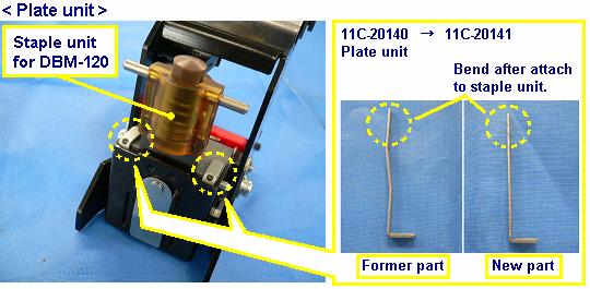
53 PRODUCT INFORMATION SHEET Duplo Corporation / Technical Support Group ( T.S.G. ) File No. # : P (C-) Date : December 00 Issues by : Hiroyuki Ubukata Model : DBM-0 (C-,), DBM-0 S/S (C-,) Unit : Staple unit Subject : Changing Purpose : Solution Implementation : Lot No. 0 S/N #000- Measures for existing machines: Parts supply : In some case, staple unit dose not staple correctly because of failing of conveyance for staples inside. To resolve this problem, the adjustment method for staple unit was changed.. In some case, staples are not formed correctly. As the result of test and inspection, it was clarified that plate unit in staple unit affected the movement of stapling. To resolve this problem, shape of plate unit was changed. Former part No. New part No. Description Qty. Compatibility Unit Assy. C-00 C-00 Staple unit for DBM-0 YES C-00 C-0 Plate unit YES C-0 C- C-0 C- Complete staple ASSY (DBM-0) Complete staple ASSY (SxS) (DBM-0 S/S) YES YES -----
54
55 00 S. Daimler Street. Santa Ana, Ca. 0 Tel: () - Fax: () - Technical Dept. Fax: () - GP-0 File No. # : P0 ( C-0A) Issue Date : February 00 Model Name : DBM-0 ( C-XX ) Subject : New kit Purpose : in the text Production : Lot No. S/N # This is new kit for DBM-0. It was designed only for to feed. inch x. inch (.mm x.mm ) paper size only to do booklet making. Production code : C- Model Name : DBM-0 Small Booklet Kit Specification :. inch x. inch Description of the kit : refer below. C-0 JOG PLATE-L unit C-0 JOG PLATE-R unit C-00 EP-ROM ( C00.hex ) Note: This is not a free upgrade. Replace parts only if necessary. For more information contact call -- service department.
56 00 S. Daimler Street. Santa Ana, Ca. 0 Tel: () - Fax: () - Technical Dept. Fax: () - GP- File No. # : P Issue Date : May 00 Model Name : DBM-0BG Subject : Special kit / pages insert kit Purpose : in the text Production : The part number for the insert kit is C-. It allows pages on a DBM-0BG model. At the bottom is the list of parts required for the kit. Description Part No. # Qty. Knife blade C-0 Knife base C-0 Center, pin C-000 Bracket C-000 Pillar C-0 Bracket C-0 Roller P0- C-0 Shaft H-00 Guide plate C-0 Knob screw 0- EP-ROM C-00 Program data file ( M type IC / hex type data ) c00.hex Note: This is not a free upgrade. Replace parts only if necessary. For more information contact call -- service department.
 Date : December 0 Model : DBM-0 (C-,,), DBM-0SxS (C-,,) DBM-0T (F-,,), DSF-000 (T-,) Unit : Switching power supply Subject : Changing Purpose : Parts discontinued Implementation : -----")
57 GP- File No. # : P (C-) Date : December 0 Model : DBM-0 (C-,,), DBM-0SxS (C-,,) DBM-0T (F-,,), DSF-000 (T-,) Unit : Switching power supply Subject : Changing Purpose : Parts discontinued Implementation : Measures for existing machines: This is not a free upgrade Parts supply : Parts upon availability Due to the parts discontinued, switching power supply used for the models mentioned above was changed. According to this changing, mounting bracket and new wires were settled. A Compatibility Former part No. New part No. Description Qty. Unit Assy. C Switching power supply YES C-0x 0-00 Switching power supply YES B F-00 Bracket YES C C-0 Wire unit YES D C-0 Wire unit YES Procedure for replacement < DBM-0, 0SxS >

 to the new switching power")

 with the")
58 . Remove the switching power supply.. Remove screws from the switching power supply removed in step.. Attach the brackets (B) to the new switching power supply (A) with the screws removed in step.. Cut the banding tie and remove the wire unit.. Attach the wire unit (C).. Attach the wire unit (D).. Attach the new switching power supply (A) with the screws removed in step. < DBM-0T >. Remove the switching power supply and wire unit.
 to the new switching power supply (A) with the screws removed in step.")
.. Attach the new switching power supply (A) with the screws removed in step.")
59 . Remove screws from the switching power supply removed in step.. Attach the brackets (B) to the new switching power supply (A) with the screws removed in step.. Attach the wire unit (C). Attach the ferrite core if it is used on the original wire unit.. Attach the wire unit (D).. Attach the new switching power supply (A) with the screws removed in step. < DSF-000 >. Remove the switching power supply and wire unit.

 with the screws removed .")
.. Attach the wire unit (D).")
60 . Remove screws from the switching power supply removed in step.. Attach the brackets (B) to the new switching power supply (A) with the screws removed in step.. Cut the banding tie on the wire unit (C).. Attach the wire unit (C).. Attach the wire unit (D).. Attach the new switching power supply (A) with the screws removed in step.
 Date : September 0 Model : DBM-0 (C-,,), DBM-0 S/S (C-,,) Unit : Stapler Subject : Changing of components Purpose : Improve driving Implementation : Lot No.")

61 GP- File No. # : P (C-) Date : September 0 Model : DBM-0 (C-,,), DBM-0 S/S (C-,,) Unit : Stapler Subject : Changing of components Purpose : Improve driving Implementation : Lot No. S/N #0000- Measures for existing machines: Parts upon availability Parts supply : This is not a free upgrade In some cases, holding pin on staple unit moves from the center position while the machine is running. It can cause trouble on the drive of stapling. To resolve this problem, shape of the attachment parts for staple unit were changed. The new parts have kept compatibility up by set. Former part No. New part No. Description Qty. Compatibility Unit Assy. A C-00 C-0 Bracket YES B C-00 C-0 Hook YES
ELECTRIC TOOL PARTS LIST
 Hitachi Power Tools LIST E933 ELECTRIC TOOL PARTS LIST SLIDE COMPOUND SAW Model 2004 2 13 (E2) 1 2 3 4 5 6 7 40 41 601 8 9 10 11 12 26 27 28 29 30 29 602 618 602 10 9 42 603 604 605 606 607 608 14 43 13
Reproduction. Not for 27" & 29" TWO STAGE INTERMEDIATE SNOWTHROWERS Parts Manual for M1227E M1227EX M1529E
 Parts Manual for 27" & 29" TWO STAGE INTERMEDIATE SNOWTHROWERS 2011 Model No. Description 1696001 M1227E 1696002 M1227EX 1696003 M1529E Briggs & Stratton Yard Power Products Group 535 Macon Road McDonough,
1650EXLT, ,
 1650EXLT, 96193008901, 2012-10 "CHASSIS, ENGINE & PULLEYS" - 000 00 00-00 W/O DESCRIPTION 1 B&S 21M307-0135-F1 FOR SERVICE & PARTS 1-800-233-3723 1 532 42 92-03 FRAME 1 2 532 15 04-06 BOLT 1 3 532 42 88-67
LIST NO. E948 SLIDE COMPOUND SAW. Model C 8FSE (E1)
") Model C FSE SLIDE COMPOUND SAW LIST E94 (E1) 42 A A 1 2 3 4 10 5 6 9 11 14 15 12 16 1 1 19 20 21 23 26 25 24 29 30 2 2 33 31 32 53 4 4 49 46 34 36 3 39 40 35 3 45 42 50 54 56 5 5 52 13 22 41 51 612 613
Model C FSE SLIDE COMPOUND SAW LIST E94 (E1) 42 A A 1 2 3 4 10 5 6 9 11 14 15 12 16 1 1 19 20 21 23 26 25 24 29 30 2 2 33 31 32 53 4 4 49 46 34 36 3 39 40 35 3 45 42 50 54 56 5 5 52 13 22 41 51 612 613
a division of Enviro Safety Products
 www.minutemanvac.com, a division of Enviro Safety Products.800.637.6606 Chassis 3 4 5 3 4 6 7 8 5 0 0 6 8 0 7 4 3 5 6 7 E 7e www.minutemanvac.com, a division of Enviro Safety Products.800.637.6606 Page
Ideal 6000 Parts Manual
 Ideal 6000 Parts Manual SIP Corporation 2006-2008 All Rights Reserved Part Number 20040-8303 SN 60501-60509 Contents Contents...2 Introduction...2 Door...3 Table...4 Front Grinding Head...6 Top Grinding
LIST NO.E078 ENGINE. ENGINE BRUSH CUTTER Model CG 27EAS (E1)
") LIST E078 (E1) ENGINE ENGINE BRUSH CUTTER Model 2010 7 16 A B 1 2 1 3 4 5 6 7 16 15 17 13 8 9 10 11 12 13 14 15 18 19 20 11 21 22 23 24 25 26 27 28 29 30 31 32 33 34 35 36 37 38 39 40 41 42 43 44 45 46
LIST E078 (E1) ENGINE ENGINE BRUSH CUTTER Model 2010 7 16 A B 1 2 1 3 4 5 6 7 16 15 17 13 8 9 10 11 12 13 14 15 18 19 20 11 21 22 23 24 25 26 27 28 29 30 31 32 33 34 35 36 37 38 39 40 41 42 43 44 45 46
ATV 90 Y-12 YOUTH 2-STROKE RED (A2004ATB2BUSR) Page 1 of 52 A-ARM, FLOOR PANEL, AND BUMPER ASSEMBLY
 Page 1 of 52 A-ARM, FLOOR PANEL, AND BUMPER ASSEMBLY") 2004 ATV 90 Y-12 YOUTH 2-STROKE RED (A2004ATB2BUSR) Page 1 of 52 A-ARM, FLOOR PANEL, AND BUMPER ASSEMBLY 2004 ATV 90 Y-12 YOUTH 2-STROKE RED (A2004ATB2BUSR) Page 2 of 52 A-ARM, FLOOR PANEL, AND BUMPER
2004 ATV 90 Y-12 YOUTH 2-STROKE RED (A2004ATB2BUSR) Page 1 of 52 A-ARM, FLOOR PANEL, AND BUMPER ASSEMBLY 2004 ATV 90 Y-12 YOUTH 2-STROKE RED (A2004ATB2BUSR) Page 2 of 52 A-ARM, FLOOR PANEL, AND BUMPER
Liste de pièces Lista de Piezas Parts List
 S Liste de pièces Lista de Piezas Parts List 4 4-14 April 014 1 1 14 1 13 13 17 8 7 1 3 4 11 1 1 0 Singer S Ref No Part No Part Name 1 800400 Front cover (unit) S NA Front cover 3 N/A Button 4 N/A Button
Parts Manual STRIKER Striker 2840 Parts List - PN Printed in USA 03/18/08
 Parts Manual STRIKER 2840 Striker 2840 Parts List - PN 238155 - Printed in USA 03/18/08 Standard Parts Recommended General Wear Parts Ref No Part Description Qty Part No 1 Squeegee Hose Assembly
I.H.S INSTALLATION INSTRUCTIONS
 I.H.S INSTALLATION INSTRUCTIONS TOOLS REQUIRED The following tools will be required for installation of your I.H.S. system. Item Qty Needed 9/16 Open End Wrench 2 3/4 Open End Wrench 1 1/2 Open End Wrench
TECHNICAL INFORMATION
 TECHNICAL INFORMATION Model No. Description RP2300FC, RP2301FC Router CONCEPT AND MAIN APPLICATIONS Models RP2300FC and RP2301FC are upgraded sister tools of our current plunge-type electronic router Model
BJC-600 BJC-600e BJC-610 BJC-620 PARTS CATALOG. Canon
 BJC-600 BJC-600e BJC-610 BJC-620 PARTS CATALOG Canon Canon BJC-600 Series Printer R 1 BJC-600 Series Printer Canon RE # PROD CODE PART NUMBER DESCRIPTION COMMENTS 1 N/A QB1-0786-000 COVER TOP BJC-600 N/A
Key No. Description Part No.
 ENGINE ASSEMBLY 45 319042 10 (SEE ENGINE MANUAL) ENGINE 12 SCREW, 5/16 18 710024 13 WASHER 120638 41 GUIDE, ROD BELT 3949 42 PLASTIC WASHER 6711 43 WASHER 120638 44 SCREW, 5/16 24X 1.00 910828 45 SPACER
MODEL TSS 305 SLIDING COMPOUND MITRE SAW
 ITEM NO PART NO DESCRIPTION PRICE 1 19500101 SUPPORT ROD 0.65 2 19500202 CLAMP BOLT 0.27 3 2668BBDA40 PAN HEAD SCREW M6X1.0-16 0.07 4 19500401 ASSIST-FENCE 13.12 5 16205505 FENCE 17.49 6 2617BBLD33 HEX
Portable Automatic Gas Cutter
 Portable Automatic Gas Cutter BHA00B20 OPERATION MANUAL For every person who will be engaged in operation and maintenance supervision, It is recommended to read through this manual before any operations,
R152SVBBC. Spare parts Ersatzteile Pièces détachées Reserve onderdelen Repuestos Reservdelar I S E R V I C E
 S E R V I C E 5 I0500103 IPL, R152SVBBC, 2005-04, 544 08 36-01 95417024202 R152SVBBC Spare parts Ersatzteile Pièces détachées Reserve onderdelen Repuestos Reservdelar 544 08 36-01 2 NO. NO. DESCRIPTION
Parts diagrams. Pick-up Roller Assembly (Figure 8-7) Pick-up Assembly (Figure 8-7) DC Controller (Figure 8-6)
 Pick-up Assembly (Figure 8-7) DC Controller (Figure 8-6)") Parts diagrams Pick-up Assembly (Figure 8-7) Pick-up Roller Assembly (Figure 8-7) DC Controller (Figure 8-6) Transfer Roller Guide Assembly (Figure 8-5) Feed Assembly (Figure 8-8) Delivery Assembly (Figure
Parts diagrams Pick-up Assembly (Figure 8-7) Pick-up Roller Assembly (Figure 8-7) DC Controller (Figure 8-6) Transfer Roller Guide Assembly (Figure 8-5) Feed Assembly (Figure 8-8) Delivery Assembly (Figure
Misaligned Folds Paper Feed Problems Double Feeds Won t Feed FLYER Won t Run iii
 Operator s Manual Table of Contents Operator Safety... 1 Introduction... 2 Unpacking and Setup... 3 Unpacking... 3 Setup... 4 FLYER Overview... 5 FLYER Diagram... 5 Capabilities... 5 Control Panel... 6
1. High Volume Finisher-MAIN
 Exploded Views and Parts List. High Volume Finisher-MAIN Exploded View Parts List No. Lvl. Loc. Material Code Description & Specification JC6-06735A PLATE-DUMMY; SL-FIN502H,EGI-SECC,0.8,223, 2 JC63-0985A
MODEL 6000SA STAMP AFFIXER Parts Manual. Postmatic, Inc.
 POSTMATIC, INC. MODEL 6000SA STAMP AFFIXER Parts Manual Postmatic, Inc. 9405 Holly Street Ste D Minneapolis, MN 55433 Phone 763-784-6046 Toll Free 888-784-6046 Fax 763-784-9433 Table of Contents Assembly
September 10, 2014 Revision 2. Puncher Unit-BE1/BF1/BG1/BH1 Service Manual
 1 4 September 10, 014 Revision Puncher Unit-BE1/BF1/BG1/BH1 Service Manual 0 0- Application This manual has been issued by Canon Inc. for qualified persons to learn technical theory, installation, maintenance,
REPAIR PART NUMBER NUMBER DESCRIPTION 0137 ELE 0136 ELE 12 VOLT SOLENOID
 PART REPAIR PART NUMBER NUMBER DESCRIPTION 0137 ELE 0136 ELE 12 VOLT SOLENOID 0203 WHL 0250 WHL WHEEL HUB 0251 WHL AXLE 0252 WHL DUST CAPS 0253 WHL TIRE - 210 SP 0204 WHL 0211 WHL TIRE & WHEEL - SP 0250
10.1 Main Unit. INDEPENDENT WHOLESALE WELDING SUPPLY Ph: Fax: Website:
 10.1 Main Unit 10.1 Main Unit 1 Case 60031802 1 2 Cross feed holder 60031803 1 3 Cross feed liner 60031804 1 4 Handle 60031805 1 5 Fan cover 60031806 1 6 Bottom plate 60031807 1 7 Heat shield 60031808
SPARE PARTS LIST. CHAIN SAWS 450, from
 SPARE PARTS LIST CHAIN SAWS 450, from 2011-09 - ACCESSORIES 450, from 2011-09 - ACCESSORIES 450, from 2011-09 - Ref Part No Description Remark QTY KIT 1 503 55 85-04 TOOL 1 CARBURETOR 450, from 2011-09
SERVICE PARTS MANUAL ICE SERIES CUBERS MODEL - ICE0250A4-T4-W4, ICE0400A3-T3-W3 MODEL - ICE0500A3-T3-W3-R4, ICE0606A3-T3-W3-R4 Includes 50Hz.
 SERVICE PARTS MANUAL ICE SERIES CUBERS MODEL - ICE0250A4-T4-W4, ICE0400A3-T3-W3 MODEL - ICE0500A3-T3-W3-R4, ICE0606A3-T3-W3-R4 Includes 50Hz. Units ICE-O-Matic 11100 East 45th Ave Denver, Colorado 80239
TRAILMATE METEOR ASSEMBLY MANUAL
 TRAILMATE METEOR ASSEMBLY MANUAL (DISC BRAKE VERSION) The Trailmate Meteor recumbent has been designed for easy assembly. This means more time to enjoy the smooth ride with single speed, 3 speed coaster
Thank you for purchasing a WIKE BOX BIKE!
 Thank you for purchasing a WIKE BOX BIKE! Contents Safety.....3 Front wheel.4 Kickstand..5 Handle Bar & Box 6 Seat post and Saddle 7 Final pre-ride check 8 Tools needed to assemble Bike: -High table or
340/430 Truck Mount Parts Manual
 340/430 Truck Mount Parts Manual Table Of Contents Page Content 1 EXTERNAL BACK ILLUSTRATION 2 EXTERNAL BACK 3 MAIN HYDRAULIC DRIVE 4 BOTTOM REAR PTO DRIVE ASSEMBLY 5 REAR SPEED REDUCTION & TUMBLER DRIVE
NPR50ACE_pl NP50A / NR50A (*Include CE) 2019/3/1 Interchangeablity
 2019/3/1 Interchangeablity") 1 1 1.BASE W083 HEX SOCKET HEAD CAP SCREW M8 25 2 Y Y Y: YES 1 2 1.BASE PM62 REAR GRIP 1 N N N: NO 1 3 1.BASE W051 HEX SOCKET HEAD CAP SCREW M5 16 2 - - - : Not used 1 4 1.BASE WL41 ROLL PIN 4 10 4 Y Y
1 1 1.BASE W083 HEX SOCKET HEAD CAP SCREW M8 25 2 Y Y Y: YES 1 2 1.BASE PM62 REAR GRIP 1 N N N: NO 1 3 1.BASE W051 HEX SOCKET HEAD CAP SCREW M5 16 2 - - - : Not used 1 4 1.BASE WL41 ROLL PIN 4 10 4 Y Y
PARTS MANUAL. Pencoed Technology Park Pencoed Bridgend CF35 5HZ Tel: Fax: E Mail:
 PARTS MANUAL Invacare UK Ltd. Pencoed Technology Park Pencoed Bridgend CF35 5HZ Tel: 05 Fax: 05 0 E Mail: ordersuk@invacare.com Invacare Ireland Unit 5, Seatown Business Campus Seatown Road Swords County
2,500/4,000 LB Easy Riser Vertical Cable Feighner Lift
 2,500/4,000 LB Easy Riser Vertical Cable Feighner Lift CAUTION - PUT SAFETY FIRST 1. Before attempting to install or operate this lift, study and fully understand the proper operating procedures and safety
K Page 1 of 48 Air Intake - Pg. 17
 K532-53168 Page 1 of 48 Air Intake - Pg. 17 Ref # Part Number Qty Description 24 25 041 06-S 1 Gasket, elbow 25 48 054 09 1 Elbow, air cleaner Discontinued not available at Kohler Co. 35 277116-S 1 Brace,
SPARE PARTS LIST BRUSHCUTTERS/CLEARING SAWS BC2145,
 SPARE PARTS LIST BRUSHCUTTERS/CLEARING SAWS BC2145, 2010-09 ACCESSORIES BC2145, 2010-09 ACCESSORIES BC2145, 2010-09 Ref Part No Description Remark QTY KIT 1 502 21 60-13 ACCESSORY BAG 1 2 501 60 02-03
SERVICE PARTS MANUAL ICE SERIES CUBERS MODEL - ICE0250A5-T5-W5, ICE0400A4-T4-W4 MODEL - ICE0500A4-T4-W4-R5, ICE0606A4-T4-W4-R5 Includes 50Hz.
 SERVICE PARTS MANUAL ICE SERIES CUBERS MODEL - ICE0250A5-T5-W5, ICE0400A4-T4-W4 MODEL - ICE0500A4-T4-W4-R5, ICE0606A4-T4-W4-R5 Includes 50Hz. Units Date 1/09 Table Of Contents This parts list contains
TECHNICAL INFORMATION
 TECHNICAL INFORMATION Models No. TD0101, TD0101F Description Impact Driver L PRODUCT P 1/ 14 CONCEPT AND MAIN APPLICATIONS Models TD0101 and TD0101F are cost-competitive 100N.m-class impact driver developed
Nordic Model CCM0330, 0430, 0530, 0630 Service Parts Manual (Includes 50Hz. Units)
") IMI CORNELIUS INC. www.cornelius.com Nordic Model CCM0330, 0430, 0530, 0630 Service Parts Manual (Includes 50Hz. Units) Publication Number: 631806058 Revision Date: October 13, 2009 Revision: E Visit the
IMI CORNELIUS INC. www.cornelius.com Nordic Model CCM0330, 0430, 0530, 0630 Service Parts Manual (Includes 50Hz. Units) Publication Number: 631806058 Revision Date: October 13, 2009 Revision: E Visit the
Installation Guide, MPower Echelon Console
 Installation Guide, MPower Echelon Console AC Performance, AC Sport and AC Performance Plus Schwinn Echelon Console (External Routing) 1. Install batteries to console. Mount the console to the bike. 2.
MB-4 PARTS LIST
 1 20 21 2 3 4 17 6 7 18 19 5 9 10 11 8 13 14 12 15 16 79 KEY PARTS DESCRIPTION 1 770506009 2 770507000 3 770565006 4 770212005 5 770215008 6 770210003 7 770539207 8 770204004 9 770205005 10 000002301 11
REPAIR PARTS MANUAL MODEL NO. EDITION 1 MFG. ID. NO Rotary Lawn Mower
 REPAIR PARTS MANUAL MODEL NO. EDITION 1 MFG. ID. NO. 96141011700 Rotary Lawn Mower 532 40 27-08 Rev. 1 01.06.06 BY Printed in U.S.A. ROTARY LAWN MOWER - - MODEL NO. EDITION 1 (96141011700) - PRODUCT NO.
Installation Instructions - Electric Aluminum Drive Systems for Arm Sets to 22 Electric Arm Systems , ,
 Installation Instructions - Electric Aluminum Drive Systems for Arm Sets to 22 Electric Arm Systems - 204-025, 206-025, 22-025 NB /0/ 607-0020 404 N. Marshall Ave. El Cajon CA. 92020 For technical support
Shoreline Cantilever Lift 2500lb Capacity Models: (108" inside width) - Part # (120" inside width) - Part #
 - Part # (120 inside width) - Part #") Shoreline Cantilever Lift 2500lb Capacity Models: 25108 (108" inside width) - Part # 1017402 25120 (120" inside width) - Part # 1017403 1. 2. 3. 4. 5. CAUTION - PUT SAFETY FIRST Before attempting to install
Shoreline Cantilever Lift 2500lb Capacity Models: 25108 (108" inside width) - Part # 1017402 25120 (120" inside width) - Part # 1017403 1. 2. 3. 4. 5. CAUTION - PUT SAFETY FIRST Before attempting to install
REPAIR PARTS MANUAL MODEL NO. BH55Y21RH MFG. ID. NO Rotary Lawn Mower
 REPAIR PARTS MANUAL MODEL NO. BH55Y21RH MFG. ID. NO. 96141000100 Rotary Lawn Mower 532 19 53-42 Rev. 1 12.08.04 BY Printed in U.S.A. ROTARY LAWN MOWER - - MODEL NO. BH55Y21RH (96141000100) - PRODUCT NO.
310 SERIES TILT-TO-LOAD ROTATOR. The Specialist In Drum Handling Equipment
 OPERATOR S MANUAL FOR MORSE TILT-TO-LOAD DRUM ROTATOR SAFETY INFORMATION: While Morse Manufacturing Co. drum handling equipment is engineered for safety and efficiency, a high degree of responsibility
OPERATIONS/PARTS MANUAL FOR PATTERSON'S WWP75H-10 HYDRAULIC WINCH.
 W. W. Patterson Company 3 Riversea Road Pittsburgh, PA 15233 Phone: 800-322-2018 FAX: 412-322-2785 OPERATIONS/PARTS MANUAL FOR PATTERSON'S WWP75H-10 HYDRAULIC WINCH. Please fill in the following blanks
MAGNETIC INDOOR CYCLING BIKE
 MAGNETIC INDOOR CYCLING BIKE SF-B1805 USER MANUAL IMPORTANT! Please retain owner s manual for maintenance and adjustment instructions. Your satisfaction is very important to us, PLEASE DO NOT RETURN UNTIL
MID-CUT AND FRONT CUT UNITS
 MID-CUT AND FRONT CUT UNITS Instructional / Parts Manual Part Number: January 00 08 ( 0 & 0 ) & Adapter Kits ( 07, 08, 09, 060, 06 & 06) Table of Contents PROWLER GRASS CATCHER TWO PACKAGED ITEMS LIST
Spare parts list ( ) Spare parts list high-pressure 9/20-4M *
 Spare parts list high-pressure 9/20-4M *") Spare parts list (5.971-969.0) Spare parts list high-pressure 9/20-4M * 05.05.2015 www.kaercher.com EN Page 2 Page 3 Page 4 Table of contents Spare parts list high-pressure 9/20-4M * (5.971-969.0)... 6
Spare parts list (5.971-969.0) Spare parts list high-pressure 9/20-4M * 05.05.2015 www.kaercher.com EN Page 2 Page 3 Page 4 Table of contents Spare parts list high-pressure 9/20-4M * (5.971-969.0)... 6
DM-MBRD (English) Dealer's Manual. ROAD MTB Trekking. City Touring/ Comfort Bike. Rear Derailleur SLX RD-M7000 DEORE RD-M6000
 Dealer's Manual. ROAD MTB Trekking. City Touring/ Comfort Bike. Rear Derailleur SLX RD-M7000 DEORE RD-M6000") (English) DM-MBRD001-04 Dealer's Manual ROAD MTB Trekking City Touring/ Comfort Bike URBAN SPORT E-BIKE Rear Derailleur SLX RD-M7000 DEORE RD-M6000 CONTENTS IMPORTANT NOTICE... 3 TO ENSURE SAFETY... 4
(English) DM-MBRD001-04 Dealer's Manual ROAD MTB Trekking City Touring/ Comfort Bike URBAN SPORT E-BIKE Rear Derailleur SLX RD-M7000 DEORE RD-M6000 CONTENTS IMPORTANT NOTICE... 3 TO ENSURE SAFETY... 4
Installing a Christie One Mount/Christie One Mount Plus
 Installing a Christie One Mount/Christie One Mount Plus This document provides instructions for installing the Christie One Mount or Christie One Mount Plus and optional accessories to mount Christie projectors
Spare parts list ( ) Spare parts list HD 2.3/14 C Ed Food
 Spare parts list HD 2.3/14 C Ed Food") Spare parts list (5.972-564.0) Spare parts list HD 2.3/14 C Ed Food 05.08.2013 www.kaercher.com EN Page 2 Page 3 Page 4 Table of contents Spare parts list HD 2.3/14 C Ed Food (5.972-564.0)... 6 10 Housing
Spare parts list (5.972-564.0) Spare parts list HD 2.3/14 C Ed Food 05.08.2013 www.kaercher.com EN Page 2 Page 3 Page 4 Table of contents Spare parts list HD 2.3/14 C Ed Food (5.972-564.0)... 6 10 Housing
DM-MARD (English) Dealer's Manual. ROAD MTB Trekking. City Touring/ Comfort Bike REAR DERAILLEUR XTR RD-M9100 RD-M9120
 Dealer's Manual. ROAD MTB Trekking. City Touring/ Comfort Bike REAR DERAILLEUR XTR RD-M9100 RD-M9120") (English) DM-MARD001-00 Dealer's Manual ROAD MTB Trekking City Touring/ Comfort Bike URBAN SPORT E-BIKE REAR DERAILLEUR XTR RD-M9100 RD-M9120 CONTENTS CONTENTS...2 IMPORTANT NOTICE...3 TO ENSURE SAFETY...4
(English) DM-MARD001-00 Dealer's Manual ROAD MTB Trekking City Touring/ Comfort Bike URBAN SPORT E-BIKE REAR DERAILLEUR XTR RD-M9100 RD-M9120 CONTENTS CONTENTS...2 IMPORTANT NOTICE...3 TO ENSURE SAFETY...4
OPERATOR S MANUAL SPREADER. CSS, VNQ [For Combine Harvester AW82V] Original instructions
![OPERATOR S MANUAL SPREADER. CSS, VNQ [For Combine Harvester AW82V] Original instructions](/thumbs/90/102423265.jpg "OPERATOR S MANUAL SPREADER. CSS, VNQ [For Combine Harvester AW82V] Original instructions") OPERATOR S MANUAL SPREADER CSS, VNQ [For Combine Harvester AW82V] en Original instructions Introduction Introduction Please read this operator s manual before using your spreader. We would first like to
OPERATOR S MANUAL SPREADER CSS, VNQ [For Combine Harvester AW82V] en Original instructions Introduction Introduction Please read this operator s manual before using your spreader. We would first like to
Quadair. Air Hockey Table Owners Manual. Assembly operation and care instuctions. Serial # Distributed By. Sales Person. Technical Service #
 Version 12.1.11 Quadair Air Hockey Table Owners Manual Assembly operation and care instuctions. Serial # Distributed By Sales Person Technical Service # QUADAIR PATENTED WORLDWIDE Forward First, we would
QUALITY ALUMINUM BOAT LIFTS, INC. INSTRUCTIONS. Dominator Lake Lift
 INSTRUCTIONS Dominator Lake Lift PHONE:251-986-3882 * FAX:251-986-3136 QABLDOMINATORINST.2014 P a g e 1 Quality Aluminum Boat Lifts, INC. Installation Instructions: Dominator Lake Lift Thank you for your
TECHNICAL DATA ZTR Model 312
 DIXON INDUSTRIES. INC. A BLOUNT COMPANY AIRPORT INDUSTRIAL PARK PO BOX 1569 COFFEYVILLE KS 67337 0945 316 251 2000 FAX 316 251 4117 TECHNICAL DATA ZTR Model 312 IMPORTANT - READ OPERATOR'S MANUAL BEFORE
Installation Instructions - Electric Steel Drive Systems for Arm Sets to ,
 Installation Instructions - Electric Steel Drive Systems for Arm Sets to 22 208-025, 209-025 NB /0/ 607-0029 404 N. Marshall Ave. El Cajon CA. 92020 For technical support call us at (800) 368-3075 Step.
GX Rower GER-ALLLX-101
 GX Rower GER-ALLLX-101 Parts Manual 11/23/2018 17:28:42 PM Table of Contents Flywheel Assembly...3 Footplate Assembly...4 Handle Assembly...5 Lower Main Frame & Seat Rail Assembly...6 Miscellaneous...7
Service Parts Manual Drawer Microwave Models: MWD24-2 & MWD30-2
 Service Parts Manual 28 14 40 49 68 29 73 5 11 55 38 75 56 4 44 8 7 45 1 52 2 22 10 46 50 71 25 26 62 15 27 3 24 48 9 39 57 13 63 39 74 36 64 51 53 50 6 35 66 42 70 21 18 37 55 16 17 76 60 33 67 19 54
6146XX-X OPEN STYLE HOSE REELS
 OPERATOR S MANUAL INCLUDING: OPERATION, INSTALLATION & MAINTENANCE 6146XX-XXX OPEN STYLE HOSE REELS LOW, MEDIUM & HIGH PRESSURE (FOR AIR, WATER & PETROLEUM PRODUCTS) 6146XX-X RELEASED: 2-5-90 REVISED:
Santa Fe Cycles Assembly Guide Introduction
 Santa Fe Cycles Assembly Guide Introduction Congratulations on your purchase of your new Santa Fe bicycle. You have purchased a bicycle that has many features and qualities. Please take a few minutes and
Nexus. Dealer's Manual. ROAD MTB Trekking. City Touring/ Comfort Bike SG-3R40 SG-3R45 SG-3R75 SG-3R75-A SG-3R75-B SG-3D55 SG-3C41
 (English) DM-SG0005-01 Dealer's Manual ROAD MTB Trekking City Touring/ Comfort Bike URBAN SPORT E-BIKE Nexus SG-3R40 SG-3R45 SG-3R75 SG-3R75-A SG-3R75-B SG-3D55 SG-3C41 SL-3S35-E SL-3S41-E SL-3S42-E SM-BC03
Installation Instructions
 116-3027, 116-3017 X-Pando Adjustable Steel Protector Installation Instructions 1404 N. Marshall Ave. El Cajon CA. 92020 For technical support call us at (800) 368-3075 NB 6/28/10 607-0112 Step 1. Mounting
Spare parts list. ( ) Spare parts list HD 3.0/20 C Ea
 Spare parts list HD 3.0/20 C Ea") Spare parts list (5.972-551.0) Spare parts list HD 3.0/20 C Ea 24.06.2016 www.kaercher.com EN Page 2 / 51 Page 3 / 51 Page 4 / 51 Table of contents Order instructions Spare parts list HD 3.0/20 C Ea (5.972-551.0)
Spare parts list (5.972-551.0) Spare parts list HD 3.0/20 C Ea 24.06.2016 www.kaercher.com EN Page 2 / 51 Page 3 / 51 Page 4 / 51 Table of contents Order instructions Spare parts list HD 3.0/20 C Ea (5.972-551.0)
Exchange Part# 2018 List Price
 List 22581-1 AIR GUN ASSY ONLY -TORQUE RITE POWER DRA $762 22581-1R $451 N/A 310-120 AIR VALVE, 3 WAY $127 N/A N/A N/A 16806-M BALLSCREW ASS'Y, Z-AXIS $1,660 N/A N/A N/A 15609-16 BALLSCREW MX 16" ENGLISH
Y:\Machine Manuals & Spare Parts Lists\PARTS BREAKDOWN\Commercial CW Gas\HD850WS Page 1
 1.0 PIECE PARTS - parts listing 1 5311-0710 Nut 1 2 5443-2820 Hose Stem 1 3 6362-3950 O-Ring Seal 14.0x1.78 1 4 6414-2820 Strainer 1 5 6313-0030 Spring 2 6 5321-1980 Handhold 1 7 5066-2120 Cover 1 8 5363-1350
SPARE PART AND OPERATION MANUAL FOOD MIXER Models W30(A), W40(A), W40P, W60(A) and W60P. Form /2009
, W40(A), W40P, W60(A) and W60P. Form /2009") Form 100 06/2009 SPARE PART AND OPERATION MANUAL FOOD MIXER Models W30(A), W40(A), W40P, W60(A) and W60P Caution -READ BEFORE OPERATING- Caution Varimixer recommends that mixer operators be at least 18
Form 100 06/2009 SPARE PART AND OPERATION MANUAL FOOD MIXER Models W30(A), W40(A), W40P, W60(A) and W60P Caution -READ BEFORE OPERATING- Caution Varimixer recommends that mixer operators be at least 18
GENEVA - CHIP BOX\ Figure Front View
 GENEVA - CHIP BOX\ Figure 5. 14-02 Front View REVERSE LOCK\ CLUTCH PULLEY ASSEMBLY MAGNET ASSEMBLY Figure 10. Clutch Drive Assembly NOTE: This is set at the factory and should not be belt take up
REPAIR PARTS MANUAL MODEL NUMBER BH55Y21RHA. Rotary Lawn Mower Rev BY Printed in U.S.A.
 REPAIR PARTS MANUAL MODEL NUMBER BH55Y21RHA Rotary Lawn Mower 532 18 92-21 Rev. 1 02.11.04 BY Printed in U.S.A. 2 ROTARY LAWN MOWER - - MODEL NO. BH55Y21RH (BH55Y21RHA) - PRODUCT NO. 964 77 46-01 ROTARY
Spare parts list. ( ) Spare parts list HD 3.0/20 C Ea
 Spare parts list HD 3.0/20 C Ea") Spare parts list (5.972-551.0) Spare parts list HD 3.0/20 C Ea 20.04.2016 www.kaercher.com EN Table of contents Order instructions Spare parts list HD 3.0/20 C Ea (5.972-551.0) 10 Housing 20 Pump set 21
Spare parts list (5.972-551.0) Spare parts list HD 3.0/20 C Ea 20.04.2016 www.kaercher.com EN Table of contents Order instructions Spare parts list HD 3.0/20 C Ea (5.972-551.0) 10 Housing 20 Pump set 21
The Crease Matic 150 is quiet in operation and the drive motor shuts down if not used for a period of time.
 KAS Crease Matic 150 The new Crease Matic 150 is a fully programmable card creaser developed specifically for the short to medium run digital print market. Designed and Manufactured in the UK. It bridges
I Illustrated Parts List 650 CRT B. Tiller. Repair Parts Manual
 Illustrated Parts List 2001-11 I0102042 650 CRT B 954328030 Repair Parts Manual Tiller HANDLE ASSEMBLY 1 532 18 06-34 Control, Throttle 2 532 00 92-66 Grip, Handle 4 532 15 92-28 Bar Assembly, Control
Bike Rack and Tire Carrier
 Bike Rack and Tire Carrier OWNER'S MANUAL Rev: 10.26.2017 Page 1 Bike Rack and Tire Carrier Owners Manual TABLE OF CONTENTS System 2 Description 2 Prior To Operation 3 Manual Slide-Out Bike Rack Operation
TR-AUGER. Section C INDEX BOOT / HOPPER
 INDEX Section C TR-AUGER BOOT / HOPPER Description Page TR80 / TR100 x 51' basic auger... C2-3 TR80 / TR100 x 61' basic auger... C4-5 TR80 / TR100 x 71' basic auger... C6-7 TR Swing hopper... C8-9 TR-Boot
SPARE PARTS LIST BRUSHCUTTERS/CLEARING SAWS FC2145 W,
 SPARE PARTS LIST BRUSHCUTTERS/CLEARING SAWS FC2145 W, 2010-09 ACCESSORIES FC2145 W, 2010-09 ACCESSORIES FC2145 W, 2010-09 Ref Part No Description Remark QTY KIT 1 502 21 60-13 ACCESSORY BAG 1 2 501 60
Meter, PD Series, E3 A1, S1 and E4 S1 Prior to 2005 Parts List
 Issue/Rev. 0.0 (2/13) Meter, PD Series, E3 A1, S1 and E4 S1 Prior to 2005 Parts List Bulletin PO01001 33 Pre 1994 39 32 31 21 Pre 1994 45 18 48 44 30 78 57 46 Note: Angled housing not shown. The Most Trusted
INSTALLATION INSTRUCTIONS
 INSTALLATION INSTRUCTIONS Accessory (ROOF) P/N 08L07-E09-100 Application 6 PILOT Publications No. Issue Date JUN 5 PARTS LIST 6 Washers Bicycle attachment 2 Brackets Hex wrench 4 Knobs 2 Keys 1 Rear Bracket
GEN20AD-GEN20AL-GEN18AN
 AD-- Parts List 02-August-16 This parts list is current as of the above revision date. See http://www.rheempartslists.net/92-42800-ad--.pdf for the current revision. Standby Generators Table of Contents
HYDRAULIC PALLET TRUCKS. MODEL Nos: PT550BC, PT685BC, PT550NC, PT685NC OPERATION & MAINTENANCE INSTRUCTIONS
 HYDRAULIC PALLET TRUCKS MODEL Nos: PT550BC, PT685BC, PT550NC, PT685NC OPERATION & MAINTENANCE INSTRUCTIONS 0711 WARNING! PT550NC MAXIMUM LOAD - 2000KG PT685NC MAXIMUM LOAD - 2000KG PT550BC MAXIMUM LOAD
FOR INSTALLING CO 2 BLENDER KIT (P/N IN BEER SYSTEM
 IMI CORNELIUS INC One Cornelius Place Anoka, MN 55303-623 Telephone (800) 238-3600 Facsimile (612) 22-326 INSTALLATION INSTRUCTIONS FOR INSTALLING CO 2 BLENDER KIT (P/N 111612000 IN BEER SYSTEM SECONDARY
Attention. Chainguards. Cranks and Chains. Flywheel Sprocket
 Attention When ordering parts for newer Schwinn IC Pro cycles reference the following service bulletins to ensure you are ordering the correct revisions. Handlebar and sleeve Chainguards Cranks and Chains
Spare parts list ( ) Spare parts list HD 2.3/15 C Ed/ 3.0/20
 Spare parts list HD 2.3/15 C Ed/ 3.0/20") Spare parts list (5.970-616.0) Spare parts list HD 2.3/15 C Ed/ 3.0/20 23.09.2011 www.kaercher.com EN Page 2 Page 3 Page 4 Table of contents Spare parts list HD 2.3/15 C Ed/ 3.0/20 (5.970-616.0)... 6 10
Spare parts list (5.970-616.0) Spare parts list HD 2.3/15 C Ed/ 3.0/20 23.09.2011 www.kaercher.com EN Page 2 Page 3 Page 4 Table of contents Spare parts list HD 2.3/15 C Ed/ 3.0/20 (5.970-616.0)... 6 10
Invacare Top End Parts Catalog
 Invacare Top End Parts Catalog T Titanium Top End Frames / Standard Parts Pre- July 2009 20 22 0 2 Pre- July 2009 9 2 2 Pre- July 2009 9 2 Titanium Head Tube Assembly see Casters / Forks on pg. 4 4 4 see
Replaces Lesco 300 & 500 Parts
 Replaces Lesco 300 & 500 Parts ItemNo R&R PartNo PartNo Description Req. Qty Price R&R Reels Available, Lifetime Guaranteed 1 R502871 020800 R&R Reel, 9 Blade, Fits 300 1 32,100 1 R502871H R&R Only R&R
LK3 B431EMark II LK3 B433EMark II Electronic Lockstitch Belt Loop Bar Tacker Electronic Lockstitch Decorative Pattern Tacker
 LK3 B431EMark II LK3 B433EMark II Electronic Lockstitch Belt Loop Bar Tacker Electronic Lockstitch Decorative Pattern Tacker Specifications LK3 B431E Mark II Electronic lockstitch belt loop bar tacker
Rear Drive System SERVICE INSTRUCTION. Specifications SI-R670B
 - SERVICE INSTRUCTION SI-R670B t Rear Drive System Before use, read these instructions carefully, and follow them for correct use. In order to realize the best performance, we recommend that the following
WEIGHT STACK ATTACHMENT. Assembly Manual (888) FOR YOUR SAFETY READ ALL INSTRUCTIONS CAREFULLY
 FOR YOUR SAFETY READ ALL INSTRUCTIONS CAREFULLY") WEIGHT STACK ATTACHMENT Assembly Manual DF835 (888) 258-0533 FOR YOUR SAFETY READ ALL INSTRUCTIONS CAREFULLY *NOTE IF YOU ARE MISSING HARDWARE OR HAVE ANY FIT UP PROBLEMS PLEASE CONTACT DELTECH FITNESS
WEIGHT STACK ATTACHMENT Assembly Manual DF835 (888) 258-0533 FOR YOUR SAFETY READ ALL INSTRUCTIONS CAREFULLY *NOTE IF YOU ARE MISSING HARDWARE OR HAVE ANY FIT UP PROBLEMS PLEASE CONTACT DELTECH FITNESS
7130 Lancer Rear Drive Magnetic Commercial Indoor Cycling Bike
 7130 Lancer Rear Drive Magnetic Commercial Indoor Cycling Bike Owner s Manual Made in Taiwan INDEX IMPORTANT SAFETY INFORMATION... 1 EXPLODED DRAWING... 2 PARTS LIST... 3 ASSEMBLY INSTRUCTION... 4-9 USER
Lock-N-Load. Bullet Feeder
 Lock-N-Load Bullet Feeder table of contents steps Overview... 2 List of required hand tools... 2 1: Mounting the Bullet Feeder to the Bench... 3 2: Mounting the Bullet Feed Hopper... 4 3: Bullet Feed Hopper
Parts: Included in the parts box: Inner Rear Tire Tray. Inner Front Tire Tray. Trail Doc Clamp. Pivot Assembly. Trail Doc Post.
 NV 2.0 2 Parts: Outer Front Tire Tray Inner Front Tire Tray Outer Rear Tire Tray Inner Rear Tire Tray Pivot Assembly Trail Doc Clamp Trail Doc Post Included in the parts box: 6mm Allen Wrench M6 Lock Washer
GX200 QX2 ENGINE, JPN, VIN# GCAE Page 1 of 34 AIR CLEANER (DUAL)
") GX200 QX2 ENGINE, JPN, VIN# GCAE-1000001 Page 1 of 34 AIR CLEANER (DUAL) GX200 QX2 ENGINE, JPN, VIN# GCAE-1000001 Page 2 of 34 Ref # Part Number Qty Description AIR CLEANER (DUAL) 1 16271-ZE1-000 1 GASKET,
GX200 QX2 ENGINE, JPN, VIN# GCAE-1000001 Page 1 of 34 AIR CLEANER (DUAL) GX200 QX2 ENGINE, JPN, VIN# GCAE-1000001 Page 2 of 34 Ref # Part Number Qty Description AIR CLEANER (DUAL) 1 16271-ZE1-000 1 GASKET,
Spare parts list ( ) Spare parts list HD 1.8/13 C Ed
 Spare parts list HD 1.8/13 C Ed") Spare parts list (5.972-842.0) Spare parts list HD 1.8/13 C Ed 26.05.2015 www.kaercher.com EN Table of contents Spare parts list HD 1.8/13 C Ed (5.972-842.0)... 6 10 Housing... 7 11 Housing... 8 12 Hand
Spare parts list (5.972-842.0) Spare parts list HD 1.8/13 C Ed 26.05.2015 www.kaercher.com EN Table of contents Spare parts list HD 1.8/13 C Ed (5.972-842.0)... 6 10 Housing... 7 11 Housing... 8 12 Hand
7 FORAGE AND HARVESTING
 Sickle Assemblies 4560R2 Sickle section, 3" x 3-1/4" underserrated. X-Hvy gauge, Chrome finish. Uses rivet RIV101. 142669H L. FT, SECTION NUMBER 141198, TYPE UND 14260 STEEL HEAT THREADED HEADS. Section
Wildcat LB Winch Kit. Operator s Manual Installation Instructions Replacement Parts List. With Wireless Control System.
 p/n 2259-560 Wildcat 4000 LB Winch Kit With Wireless Control System Operator s Manual Installation Instructions Replacement Parts List 2012 Arctic Cat Inc. Trademarks of Arctic Cat Inc. Thief River Falls,
Reproduction. Not for. Parts Manual. VCS404 16" Walk Behind Mower. Models
 Parts Manual Models Mfg. No. Description VCS404-BA Vantage 16" Walk Behind Mower VCS404-BB Vantage 16" Walk Behind Mower VCS404-BC Vantage 16" Walk Behind Mower VCS404 16" Walk Behind Mower Manual Part
INDOOR BIKE MANUAL
 INDOOR BIKE 91022 MANUAL 91022 INSTRUCTIONS FOR USE 1) The model 91022 is designed to be used as light commercial use or home use. It has a fixed wheel driven flywheel and should be used under professional
Spare parts list ( ) Spare parts list HDS 990
 Spare parts list HDS 990") Spare parts list (5.952-855.0) Spare parts list HDS 990 13.10.2014 www.kaercher.com EN Page 2 Page 3 Page 4 Table of contents Spare parts list HDS 990 (5.952-855.0)... 6 10 Individual parts... 7 49 Spare
Spare parts list (5.952-855.0) Spare parts list HDS 990 13.10.2014 www.kaercher.com EN Page 2 Page 3 Page 4 Table of contents Spare parts list HDS 990 (5.952-855.0)... 6 10 Individual parts... 7 49 Spare
Assembly Instructions And User Guide
 EZ-1/EZ-CLASSIC QUADRIBENT By Blackbird Designs Inc. Mark 5.2 June 2011 Assembly Instructions And User Guide 1 The Quadribent is 2-seat, side-by-side, human powered vehicle that enables almost anyone to
R152SVH. Spare parts Ersatzteile Pièces détachées Reserve onderdelen Repuestos Reservdelar
 SERVICE I0700098 IPL, R152 SVH, 2007-03, 544 39 00-02 96141013300 R152SVH Spare parts Ersatzteile Pièces détachées Reserve onderdelen Repuestos Reservdelar 544 39 00-02 2 4 3 1 532 19 05-82 Handle, Grassbag,
Bike Rack and Spare Tire Carrier 1-1/4" Receiver
 Bike Rack and Spare Tire Carrier 1-1/4" Receiver OWNER'S MANUAL Rev: 11.15.2017 Page 1 Bike Tire Carrier 1.25 Owners Manual TABLE OF CONTENTS Safety Information 2 Product Information 2 Installation 3 Installation