IMO REVISION OF THE INTACT STABILITY CODE. Evaluation of the roll prediction method in the weather criterion. Submitted by the United Kingdom
|
|
|
- Lynne Collins
- 6 years ago
- Views:
Transcription

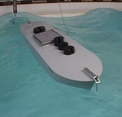
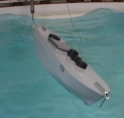
1 INTERNATIONAL MARITIME ORGANIZATION E IMO SUB-COMMITTEE ON STABILITY AND LOAD LINES AND ON FISHING VESSELS SAFETY 51st session Agenda item 4 SLF 51/INF.2 April 28 ENGLISH ONLY REVISION OF THE INTACT STABILITY CODE Evaluation of the roll prediction method in the weather criterion Submitted by the United Kingdom Executive summary: Strategic direction: 5.2 High-level action: Planned output: Action to be taken: Paragraph 11 Related documents: Introduction SUMMARY The United Kingdom submits the results of a research project investigating the IMO severe wind and rolling criterion (resolution A.562(14)) using physical modelling of five domestic ships to determine rolling angle in waves. Some suggestions for amending the parameters contained in resolution A.562(14) are discussed. Resolution A.749(18), as amended by resolution MSC.75(69); SLF 48/4/5; SLF 49/5; SLF 45/6/5; SLF 45/6/3; SLF 46/6/ and SLF 46/6/7 1.1 Tests were conducted in a towing tank, in regular beam seas representative of the conditions assumed by the weather criterion. The models were unrestrained. In each case a range of wave frequencies was used, and the maximum roll response determined from gyroscope measurements. The very steep waves assumed in the criterion resulted in significant difficulties, requiring some development of the testing and analysis techniques. 1.2 Comparisons were made between the measured values of roll period and roll angle, with those predicted by the weather criterion. Correlation was poor in most cases, with measured roll angles being higher than predicted values for models with low beam to draught ratios, and measured values lower than predicted for high beam to draught ratios. For vessels without bilge keels the correlation was very poor, with measured roll angles considerably higher than those predicted. For reasons of economy, this document is printed in a limited number. Delegates are kindly asked to bring their copies to meetings and not to request additional copies. I:\SLF\51\INF-2.doc
2 SLF 51/INF Selection of models 2.1 The stated aim of the project was to compare performances of models of hull forms of conventional, with those of extreme, proportions. The term conventional refers to beam/draught ratios within the range covered by the weather criterion, that is, in the range 2.4 to 3.5. Two models of conventional form were envisaged, with three others distributed within the range of higher beam/draught ratios. 2.2 Four other vessels were selected with various forms of round bilge and chine hulls. The actual beam/draught ratios of the vessels ranged from 3.6 to Principal dimensions of the vessels modelled are presented in table 1, and photographs are presented in figure 5. At the request of the vessel designers and owners, the modelled vessels have not been identified in this report. They are referred to by their Wolfson Unit model number. The models did not include hull structure above the upper deck, stern overhangs or vehicle ramps, so the LOA values quoted typically are 1 2 metres less than the vessels upon which the models were based. Model construction 3 For each vessel a model scale was selected that would enable tests to be conducted in regular waves corresponding to those assumed in the weather criterion. This resulted in the use of models about 1.8 metres in length, and smaller than recommended by the testing guidelines given in Ref.5. The possibility of scale effects on roll damping therefore was a consideration. For this reason, the models of round bilge or double chine form were tested with bilge keels fitted to minimize scale effects, and in some cases the keels were made deeper than those on the full size vessel. Other centreline keels and skegs were fitted as designed. Test conditions 4.1 In general, the models were tested in a loading condition taken from their stability booklet. This was supplemented with additional conditions selected to provide a range of parameters and address specific items of interest. Variations included testing at alternative displacements, vertical centres of gravity, and with different bilge keel configurations. A full list of test conditions is presented in table 1. The model conditions are identified by the model number, with additional letters to indicate light or heavy displacement, an alternative KG and the presence of bilge keels. 4.2 The distribution of the model conditions, in terms of their length, beam and draught, are presented in relation to the smaller vessels in the United Kingdom fleet in figure 6. The tested beam/draught ratios ranged from 3.3 to 6.23 and, although some vessels in the fleet have more extreme beam/draught ratios, this range is representative of the majority of the fleet. 4.3 Figure 7 presents the angles of maximum GZ value for the test conditions, again in relation to the available data for the fleet, and the GZ curves for each test condition are presented in figure Each model was tested at more than one displacement. In some cases the GM was kept constant, but in others a different GM was used in order to obtain a condition such that the required test wave heights were within the capability of the towing tank. 4.5 In all test conditions the roll inertial was adjusted to a radius of gyration equal to.35b. I:\SLF\51\INF-2.doc
3 - 3 - SLF 51/INF.2 Roll decrement tests 5 Prior to testing in waves, roll decrement tests were conducted on each model configuration. These provided a measurement of the model natural roll period, which was used to determine the appropriate wave steepness factor, s, as defined in the weather criterion, and as a basis for the selection of wave frequencies in the roll response tests. An example of a roll decrement record is presented in figure 9. The roll period was determined from the time taken for a number of complete roll cycles, typically about. Test technique 6.1 The model was tracked by a lightweight movable carriage, propelled manually to maintain its position relative to the model. The carriage supported the umbilical and carried all instrumentation including a wave probe and video camera. This technique enabled one experimenter to maintain model alignment and ensure that the model remained in the video camera s field of view. It also provided a local measurement of the waves encountered. The wave probe was located between one end of the model and the tank side, where waves reflected from the model might cause some interference, but it was considered that such measurements might be of use in the analysis. 6.2 A second wave probe was mounted in a fixed location between the model and the wave maker. This was at a sufficient distance from the model to eliminate any interference with the wave measurement from waves generated by the model s motion. Data monitored with this probe are presented in figure. 6.3 Tests were commenced with the model 3 metres from the wave maker, and in most cases the model drifted down wave for a distance of several metres. 6.4 The guidelines for testing given in Ref.5 suggest the following ratios of wave frequency to natural roll frequency:.8,.9,.95,.975, 1., 1.5 and 1.2. In some cases these test points were found to be inappropriate because the encounter frequency was significantly different to the wave frequency. Wave frequencies therefore were selected as the tests proceeded, such that they enabled the relationship between roll response and wave frequency to be defined adequately for the purpose of the project. Data analysis Measured wave height 7.1 Because the waves generated were very steep, and sometimes breaking, the waves encountered by the model were not as regular as would be the case if generating waves of lower slope. This is a known problem with simulation of the weather criterion conditions, and is one of the reasons for the alternative methods of testing described in Reference The wave height measurements were used to obtain a mean value for each run, and these were collated at the end of the test programme, as presented in figure. The data were used to derive a mean curve, also presented on the graph, and this was used in the final analysis of the experimental data, in preference to the measured data for each run. It was considered that this procedure offered better accuracy and consistency, and it enabled data to be incorporated for a small number of tests where reliable wave records were not available. I:\SLF\51\INF-2.doc
4 SLF 51/INF Natural roll period 7.3 The roll decrement test records were analysed to determine the time between successive peaks in the roll motion, and hence the natural roll period. The period varies slightly with roll angle, as can be seen in figure 11, where the model scale roll periods are presented for different model configurations. Wave steepness factor 7.4 In the analysis following the tests, figure 11 was used to determine a more accurate value of the wave steepness required by the weather criterion, using the natural roll period at the angle corresponding to the maximum roll response to the waves. In most cases the variation of period with roll angle is small, and all of the wave steepness values were in the range.92 to.1, so the final values were the same or very close to those obtained from the initial roll decrement analysis, where a value was obtained from about cycles. 7.5 Because, in some cases, there were differences between the predicted natural roll period and the measured period, the values of wave steepness factor used in the test analysis were not necessarily the same as those used in the weather criterion prediction. Roll angles in waves 7.6 The average roll amplitude and encounter frequency were determined from these gyro records, over as large a number of cycles as possible. 7.7 These values then were adjusted by the factor Wave Height Required / Wave Height Used. The wave height required was that assumed in the weather criterion, using the natural roll period and wave steepness determined as described in section The wave height used was that determined as described in section This adjustment was made on the assumption that the roll angle of the model was proportional to the wave height at that wave frequency. It is recognized that the roll motion at large amplitudes is non-linear, but it was considered that these small adjustments to the data were acceptable. In most cases they had a smoothing effect on the plots of roll angle against frequency. 7.9 The adjusted average roll angles are presented in figure 12, plotted against the ratio of wave frequency to model natural frequency. In most cases the maximum roll angle occurred in waves of frequency similar to the model natural frequency. Whilst one might expect such a result for a stationary model, it was rather surprising where models drifted with the waves so that the encounter frequency was lower than the wave frequency. The data are presented in a similar way in figure 14, but in relation to the encounter frequency rather than the wave frequency. Unfortunately the data file for M915 was lost prior to generating these plots, so is absent from the latter. 7. In some cases the roll angles were slightly asymmetric about upright, zero roll. In such cases the roll angles towards the waves, as addressed by the weather criterion, tended to be less than those away from the waves. In all cases, however, the roll angles presented are an average of the port and starboard values, as appears to have been customary in other studies. With a beam wind the ship would have a different equilibrium attitude and no attempt was made to simulate this in the tests, because the models represented hull forms only, and different superstructure arrangements would result in different wind heeling moments. Initial heel might affect the results but such effects were not expected to have a significant bearing on the result of this project. I:\SLF\51\INF-2.doc
5 - 5 - SLF 51/INF.2 Maximum roll angles 7.11 The maximum roll angle for each model configuration was determined by inspection of the curves presented in figure 12. These maxima are shown on the GZ curves for each model in figure 8. Observations of roll motion 8 None of the models appeared to be in danger of capsizing during these tests, although M915 rolled to very large angles, where its stability in calm water was negligible. The waterlines at the roll angles measured do not correspond to those that would occur at the same roll angles in calm water, and the relationship depends on the wave frequency, as illustrated in figure 13. If the vessel is in relatively long waves, so that the motion is in phase with the waves, the angle of the local wave surface relative to the hull will be less than at the same roll angle in calm water. In short waves, when the roll motion is out of phase, the water surface inclination will be relatively high. This will have implications for the likelihood of water on deck, and perhaps downflooding. It is one of the reasons frequently cited in the argument against using calm water stability characteristics in safety assessment. The finding from Ref.2, however, was that vessels in waves tend to capsize only when their roll angle exceeds their range of positive stability in calm water. There is no evidence to suggest that a vessel may be in danger of capsizing because the angle of the wave surface relative to the hull exceeds the range of positive stability. Comparison of results with weather criterion predictions Roll period 9.1 The measured roll periods are compared with those predicted by the weather criterion in figure 15. In most cases the measured and predicted values were within 2 or 3%, but in some cases the measured values were substantially less than those predicted. This is particularly noticeable for the models without keels. 9.2 These results reflect similar findings by experimenters in Italy, Ref.8, who found that the weather criterion provided an overestimate of the roll period. Maximum roll angles 9.3 The maximum roll angles are presented in figure 17 to show their variation with beam/draught ratio. For clarity, figure 17 is divided into two graphs, with models without bilge keels displayed on the first, and those with on the second. 9.4 For comparison with weather criterion predictions, three points are presented for each model configuration: Those labelled SWRC are the values of roll angle calculated using the current formulation of the weather criterion. Those labelled Proposed are the values calculated using proposals made to IMO (Refs. 9 and 11) for adjustments to r, s and X 1. However the second of these is inapplicable for the models tested; only being relevant for vessels with large roll periods. The third points are the Measured values derived from these tests. The effects of keels and skegs 9.5 The predicted values presented in figure 17 were calculated on the assumption that all lateral keel areas should be included in the calculation of Ak. The Intact Stability Code defines Ak as total overall area of bilge keels, or area of the lateral projection of the bar keel, or sum of I:\SLF\51\INF-2.doc
6 SLF 51/INF these areas. Inspection of calculations approved by the administration, and correspondence with consultants, suggested differences of interpretation as to areas allowable for inclusion. In some cases all keels, skegs and thruster struts were included, whereas in other cases only bilge keels and bar keels had been allowed. To quantify the effects of such differences the predictions presented in figure 17 were re-calculated with all centreline keels and skegs excluded. Although the Code specifies that bar keels should be included, on these models their areas were small in relation to the skegs, and to include them would have required some subjective judgment regarding their definitions. Excluding all centreline keel areas therefore was a simpler option. This affected models M915, M929, M935, and their variants. The alternative derivations of the factor k are shown in table 3, where the differences have been highlighted, and revised versions of the roll angle plots are presented in figure The effect of reducing the keel area is to increase the predicted roll angle because of the reduction in damping. The relevant factor, k, is limited however, and may not be less than.7 regardless of how large the area of keels might be. 9.7 Correlation between the measured roll angles and the values predicted is closer with the centre keels excluded. This is most noticeable for the models without bilge keels. The centreline keels and skegs contribute to the damping in a similar way to bilge keels, and so it does not seem reasonable to exclude them in the predictions. The closer correlation perhaps is misleading and should be treated with caution. The definition of sharp bilges 9.8 The weather criterion specifies the minimum value of the factor k, of.7, for a ship having sharp bilges. An interpretation of this term has been proposed as meaning bilge radius is smaller than 1% of the ship s breadth and the angle between piece-wise lines representing the bilge is smaller than Model M928 has very sharp bilges, but has a high B/d ratio, where few of the weather criterion predictions correlate well with the measured values. M937 has a double chine hull form that some might interpret as sharp bilges. The weather criterion predictions were calculated for this model, and its variant M937H, using k values of 1. and.7, and using both the current and proposed IMO factors. The results are tabulated below, together with the measured values. Model Predicted roll Predicted roll Predicted roll Predicted roll Proposed adjustments to IMO Current IMO method method k=.7 k=1. k=.7 k=1. Measured roll M M937H The closest correlation with the measured value is highlighted in each case. In one case the current method provides the closest correlation and in the other closer correlation is with the proposed adjustments. In both cases, however, the values calculated assuming that the vessel has round bilges give the best correlation. It appears this double chine form therefore should be considered as equivalent to a round bilge vessel in terms of the damping offered by these soft chines. I:\SLF\51\INF-2.doc
7 - 7 - SLF 51/INF This result supports the definition given in Ref.5, because the angles at both of the chines are greater than 12 degrees. Possible adjustments to the weather criterion.1 It should be noted that on the basis of these test results one may attempt to adjust one or more factors in the weather criterion method. Effective wave slope coefficient.2 The formula used for this factor, r, in the weather criterion is an approximate one. The Froude-Krylov hypothesis gives a rather more complicated formula, as presented in Ref.3, and again in Ref.7, but this has been considered inappropriate for general regulatory purposes. The Froude-Krylov formula was used to calculate the effective wave slope coefficients for the model configurations to assess the validity of the weather criterion approximation. The results are presented in figure It is apparent that the approximate formula gives an overestimate of the coefficient. This supports the findings presented in Ref.7, which concludes that the approximate formula provides small craft with excessive exciting roll moment. The graph also provides some support the proposal to IMO to limit r to a maximum value of If these calculated values of r are substituted into the weather criterion predictions, they reduce the predicted roll angles in most cases. This results in greater differences between the predicted values and those measured in the tests, as illustrated by comparison of figure 23 with figure 17. Damping Factor X1.5 Together with the effective wave slope coefficient, this was also the subject of the Russian submission to the IMO where an extension of the tabulated values of X1 was proposed. Assuming that all other factors of the current formula are valid, we may derive values for X1 that would give predicted roll angles equal to the measured values. The result is illustrated in figure 24, where the differences between the values presented in figure 17 have been eliminated by adjusting the value of X1 as necessary. A solid line has been fitted through the data to indicate the relationship that these results suggest for the variation of X1 with B/d. The data for models without keels or chines (M915, M929, M929H and M929L) have not been included here. Much greater X1 values would be required to correlate their measured and calculated roll angles..6 A second data set is presented in figure 24, fitted with a broken line, and these values have been calculated in the same way, but assuming that the values of r are not greater than It is interesting to note that the lines intersect the line for the Russian proposal near the middle of its B/d range, but are parallel with the IMO line, denoted SWRC on the graph. Although the Russian proposal has been harmonized with the current IMO tabulated values, it does not form a fair extension of the original line, and the existing IMO values were not affected. The Russian proposal was formulated following model tests on 15 vessels ranging in length from 5 to 182 metres. Ten of the vessels had B/d ratios between 3.6 and 5, and the remaining five extended the range up to Their results are presented in Ref.21. This includes a graph similar to figure 24, but with very little scatter of the data points through which their curve was fitted. I:\SLF\51\INF-2.doc
8 SLF 51/INF Action requested of the Sub-Committee 11 The Sub-Committee is invited to take note of the information provided. A full copy of the report, Research Project 571, can be downloaded from: I:\SLF\51\INF-2.doc
9 - 9 - SLF 51/INF.2 References: 1 European Council. Council Directive 98/18/EC on Safety Rules and Standards for Passenger Ships. 1998L18 - EN IMO. Code on Intact Stability for All Types of Ships Covered by IMO Instruments, Resolution A.749(18) as amended by resolution MSC.75(69) Watanabe Y. Some Contributions to the Theory of Rolling. Trans.RINA 8, Japan. Proposal on Draft Explanatory Notes to the Severe Wind and Rolling Criterion. SLF 48/4/ IMO. 5 Germany. Revised Intact Stability Code prepared by the Intersessional Correspondence Group. SLF 49/ IMO. 6 Yamagata M: Standard of Stability Adopted in Japan. Trans RINA 1: Fujino M, Fuji I, Hamamoto M, Ikeda Y, Ishida S, Morita T, Tanai K, Umeda N. Examination of Roll Damping Coefficients and Effective Wave Slope Coefficients for Small Passenger Craft. Proc.US Coast Guard Vessel Stability Symposium US Coast Guard Academy. 8 Francescutto A, Serra A. Experimental Tests on Ships with Large Values of B/T, OG/T and Roll Period. Proceedings of the 6th International Ship Stability Workshop. 22. Webb Institute. 9 Italy. Weather Criterion for Large Passenger Ships. SLF 45/6/ IMO. Germany. Remarks Concerning the Weather Criterion. SLF 45/6/ IMO. 11 Russia. Severe Wind and Rolling Criterion (Weather Criterion). SLF 46/6/. 23. IMO. 12 Francescutto A: Intact ship stability: The way ahead. Marine Technology and SNAME News 41: Germany. Calculations using the proposed factors s and r for the weather criterion. SLF 46/6/ IMO. 14 Betaglia G, Serra A, Francescutto A, Bulian G. Experimental Evaluation of the Parameters for the Weather Criterion. STAB 23, Japan. Comments on draft guidelines for alternative assessment of weather criterion based on trial experiment results. 25. IMO. 16 Hyeon Kyu, et al. Application and Review on Interim Guidelines for Alternative Assessment of the Weather Criterion. STAB Ishida S, Harukuni T, Hiroshi S. Evaluation of the Weather Criterion by Experiments and its Effect to the Design of a RoPax Ferry. STAB Umeda N, Paroka D, Hashimoto H, Ueda J, Bulian G, Examination of Experiment- Supported Weather Criterion with a RoPax Ferry Model. The Japanese Ship Ocean Engineering Meeting seminar dissertation collection 2nd number Francescutto A, Serra A, Bulian G. Weather Criterion Wolfson Unit. MCA Research Project 59: HSC Evaluation of Existing Criteria. 25. MCA. 21 Lugovsky V.V., Luzyanin A.A. The Main Principles of Reconciliation Calculation Methods for the Roll Amplitude in the RS Rules and the IMO Code on Stability Requirements. Trans of Russian Maritime Register of Shipping 23: 2. (In Russian) 22 Vassalos D, Jasionowski A, Cichowicz J. Issues Related to the Weather Criterion. International Shipbuilding Progress 51: , Blome T, Krueger S. Evaluation of the IMO Weather Criterion for Passenger Ships by Direct Calculation of Capsizing Frequencies. Passenger Ship Safety, 23. RINA. *** I:\SLF\51\INF-2.doc
10
11 Table 1 Principal dimensions of the vessels modelled Model LOA LWL BWL d B/d Disp. Cb KG GM OG/d Scale m m m m tonnes m m Models without bilge keels M M M929H M929L M M937H Models with bilge keels M915K M915HK M M928G M928H M929K M929HK M929LK M935K M935LK M935HK M937K M937HK Table 2 Weather criterion calculation Model C T OG/d k X1 X2 r s θ1 X1 r θ1 Using current weather criterion Using proposed mods Models without bilge keels M M M929H M929L M M937H Models with bilge keels M915K M915HK M M928G M928H M929K M929HK M929LK M935K M935LK M935HK M937K M937HK
12 Table 3 Alternative derivations of the factor k Model Area of keel Area of bilge Total area, & skegs keels A k A k/lb k A k/lb k m^2 m^2 m^2 All keels & skegs included Bilge keels only Models without bilge keels M M M929H M929L M M937H Models with bilge keels M915K M915HK M M928G M928H M929K M929HK M929LK M935K M935LK M935HK M937K M937HK Table 4 Measured values of the damping coefficient, N Model Measured 2 Models without bilge keels M M M929H..9 M929L..9 M M937H.7.9 Models with bilge keels M915K M915HK M M928G.3.45 M928H M929K M929HK.3.41 M929LK M935K M935LK M935HK M937K M937HK
13 Table 5 Wave characteristics assumed by the weather criterion for the vessels modelled Model LOA T s Wave length Wave height Probable Measured Beaufort m s m m Force M M M929H M929L M M937H M915K M915HK M M928G M928H M929K M929HK M929LK M935K M935LK M935HK M937K M937HK
14 Figure 1 Factors presented in the IMO Weather Criterion X X B/d CB k Round bilges, no keels: k = 1. Sharp bilges, no keels: k =.7 Wave Steepness, s Ak/LB Roll Period, T - seconds Figure 2 Proposed adjustments to factors presented in the IMO Weather Criterion SWRC Russian Proposal. SWRC Italian Proposal.9.8 X Wave Steepness, s B/d Roll Period, T - seconds 24
15 Figure 3 Variation of length, beam and draught within the UK fleet Beam - metres 2 15 LOA/Beam No data on SWRC 4 Pass SWRC Fail SWRC LOA - metres LOA - metres Draught - metres Beam/Draught B/d range covered by current method LOA - metres LOA - metres 25
16 Figure 4 Variation of the angle of maximum GZ with the beam/draught ratio 5 45 No data on SWRC Pass SWRC Fail SWRC 4 Angle of GZmax - degrees Beam/Draught 26
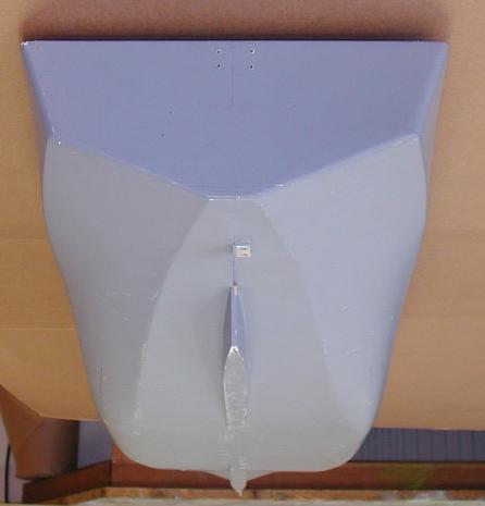
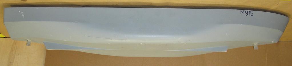
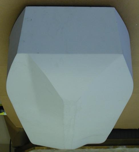
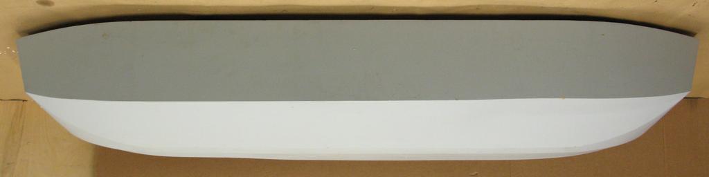
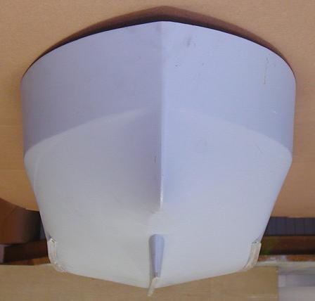
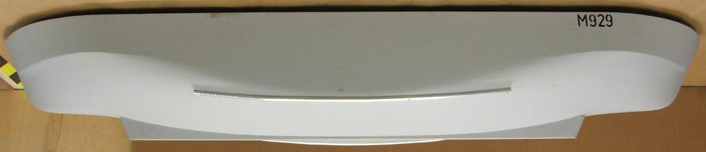
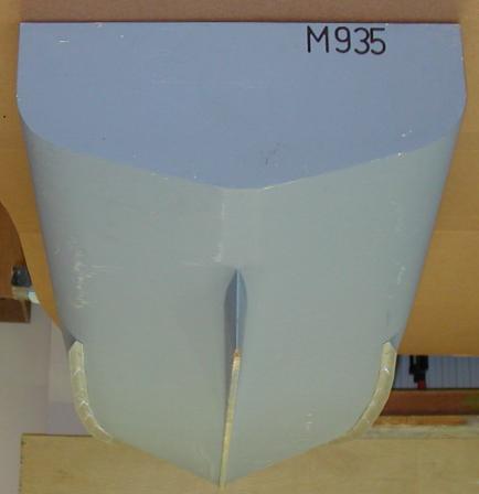
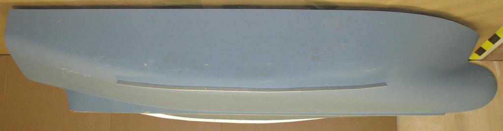
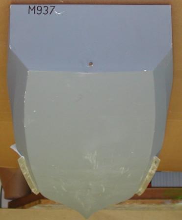
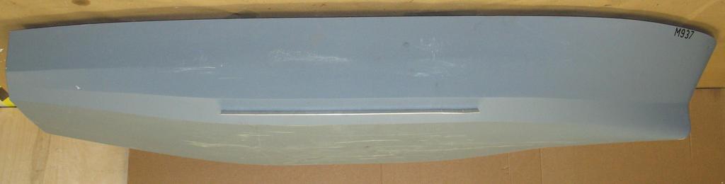
17 Figure 5 Photographs of the models, from the stern and starboard side M915 M928 M929 M935 M937 27
18 Figure 6 Distribution of the model configurations in relation to the fleet Beam - metres UK Fleet Models LOA - metres 8 LOA / Beam LOA - metres Beam / Draught B/d range covered by current method LOA - metres 28
19 Figure 7 Angles of maximum GZ for the models, compared with those of the fleet 55 5 Fleet Models 45 Angle of GZmax - degrees Beam/Draught 29
20 Figure 8 GZ curves of the tested model conditions GZ - metres M915 M915H Roll angle, no keels Roll angle with keels GZ - metres M M928G M928H GZ - metres M929L 1..5 M929 M929H GZ - metres M935L 1..5 M935 M935H GZ - metres M M937H Angle of Heel - degrees 3
21 Figure 9 Example of a roll decrement record 4 M937HK, Run 137b 3 2 Roll Angle - degrees Time - seconds Figure Variation of measured mean wave heights 4 Wave Height Measured - mm Wave Height Input to Wavemaker - mm 31
22 Figure 11 Model roll period data derived from roll decrement tests Roll Period - seconds Roll Period - seconds Roll Period - seconds Roll Period - seconds Roll Period - seconds M915K M915HK M M928H M928G M929 M929H 1.2 M929L M929K 1. M929HK M929LK M935K 1. M935HK M935LK M937 M937H 1. M937K M937HK Roll Angle - degrees 32
23 Figure 12 Variation of roll angle with wave frequency for all model configurations 5 5 M M928G Roll Angle - degrees 3 2 M915 M915K Roll Angle - degrees 3 2 M928H M915HK Wave frequency / Model natural frequency Wave frequency / Model natural frequency 5 Roll Angle - degrees M929 M929H M929L M929K M929HK M929LK Wave frequency / Model natural frequency 5 5 M937 M937H M937K 4 4 M937HK Roll Angle - degrees 3 2 M935K M935HK Roll Angle - degrees 3 2 M935LK Wave frequency / Model natural frequency Wave frequency / Model natural frequency 33


24 Figure 13 M929H at various positions on the wave, for different wave frequencies Run 49. Wave frequency / model natural frequency = 1.25 Trough Face Crest Back Run 52. Wave frequency / model natural frequency = 1.17 Trough Face Crest Back Run 53. Wave frequency / model natural frequency = 1.5 Trough Face Crest Back Run 54. Wave frequency / model natural frequency =.9 Trough Face Crest Back Waves are travelling from right to left. 34
25 Figure 14 Variation of roll angle with encounter frequency for all model configurations 5 5 M M928G Roll Angle - degrees 3 2 M915K Roll Angle - degrees 3 2 M928H M915HK Model encounter frequency / Model natural frequency Model encounter frequency / Model natural frequency 5 Roll Angle - degrees M929 M929H M929L M929K M929HK M929LK Model encounter frequency / Model natural frequency 5 5 M937 M937H M937K M937HK Roll Angle - degrees M935K M935HK M935LK Roll Angle - degrees Model encounter frequency / Model natural frequency Model encounter frequency / Model natural frequency 35
26 Figure 15 Measured natural roll periods compared with values predicted by the weather criterion Natural Roll Period Measure/Predicted No bilge keels With bilge keels M935HK M929LK M915K M928G M935K M935LK M929K M915HK M928 M929HK M929L M937K M928H M929 M937HK M929H M915 M937 M937H Beam/Draught Figure 16 Comparison of calculated and measured values of the roll period coefficient, C.55 No bilge keels.55 No bilge keels With bilge keels With bilge keels Measured values, model k =.35B % -7.5% Adjusted values, for model k =.4B Calculated values from Morita's formula Calculated values from Morita's formula 36
27 Figure 17 Maximum roll angles presented in relation to the beam/draught ratio Models tested without keels or chines Maximum Roll Angle - degrees 3 2 SWRC Proposed Measured Beam/Draught 3 Models tested with keels or chines Maximum Roll Angle - degrees 2 SWRC Proposed Measured Beam/Draught 37
28 Figure 18 Estimated maximum roll angles for models ballasted to radius of gyration =.4B Models tested without keels or chines Maximum Roll Angle - degrees 3 2 SWRC Proposed Measured, k=.35b Estimated, if k=.4b Beam/Draught 3 Models tested with keels or chines Maximum Roll Angle - degrees 2 SWRC Proposed Measured, k=.35b Estimated, if k=.4b Beam/Draught 38
29 Figure 19 Maximum roll angles compared with predictions calculated with centreline keels and skegs excluded Predictions with centre keels & skegs excluded Models tested without keels or chines Maximum Roll Angle - degrees 3 2 SWRC Proposed Measured Beam/Draught 3 Models tested with keels or chines Maximum Roll Angle - degrees 2 SWRC Proposed Measured Beam/Draught 39

30 Figure 2 Examples of N coefficients measured in model experiments, as presented in Ref.5 Figure 21 N coefficients derived for the models in this study M937HK M937K M935HK M935LK M935K M929LK M929HK M929K M928H M928G M928 M915HK M915K N at 2 degrees N at degrees M937H M937 M929L M929H M929 M N 4
31 Figure 22 Effective wave slope coefficients for the models compared with the predicted values Effective Wave Slope Coefficient, r Model configurations IMO Proposed OG/d Figure 23 Roll angles compared with calculations using the proposed values of X1 with values of r calculated using the Froude-Krylov hypothesis Models tested without keels or chines Maximum Roll Angle - degrees 3 2 X1 Proposed, r F-K Measured Beam/Draught 3 Models tested with keels or chines Maximum Roll Angle - degrees 2 X1 Proposed, r F-K Measured Beam/Draught 41
32 Figure 24 Values of X 1 required for accurate prediction of the model results SWRC Russian Proposal Values required, using r from SWRC SWRC Russian Proposal Values required, using proposed r Models with bilge keels or chines only X1.8 X B/d B/d Figure 25 Correlation of other model test results with the weather criterion Maximum Roll Angle - degrees 3 2 SWRC Measured, Italy Measured, Japan Beam/Draught 42
33 Figure 26 Ratio of measured to calculated roll angles, including data by other experimenters 2. Models tested without keels or chines Measured / Predicted Roll Angle SWRC Proposed Beam/Draught 1.5 Models tested with keels or chines Measured / Predicted Roll Angle 1..5 SWRC Proposed Italy Japan Beam/Draught 43
EVALUATION OF THE ROLL PREDICTION METHOD IN THE WEATHER CRITERION
 EVALUATION OF THE ROLL PREDICTION METHOD IN THE WEATHER CRITERION B Deakin, Wolfson Unit MTIA, University of Southampton, UK SUMMARY This paper describes some background to the IMO Severe Wind and Rolling
IMO REVISION OF THE INTACT STABILITY CODE. Proposal of methodology of direct assessment for stability under dead ship condition. Submitted by Japan
 INTERNATIONAL MARITIME ORGANIZATION E IMO SUB-COMMITTEE ON STABILITY AND LOAD LINES AND ON FISHING VESSELS SAFETY 49th session Agenda item 5 SLF 49/5/5 19 May 2006 Original: ENGLISH REVISION OF THE INTACT
ITTC Recommended Procedures and Guidelines
 Page 1 of 6 Table of Contents 1. PURPOSE...2 2. PARAMETERS...2 2.1 General Considerations...2 3 DESCRIPTION OF PROCEDURE...2 3.1 Model Design and Construction...2 3.2 Measurements...3 3.5 Execution of
Experimental Study on the Large Roll Motion of a ROPAX Ship in the Following and Quartering Waves
 Experimental Study on the Large Roll Motion of a ROPAX Ship in the Following and Quartering Waves Sun Young Kim, Nam Sun Son, Hyeon Kyu Yoon Maritime & Ocean Engineering Research Institute, KORDI ABSTRACT
RESOLUTION MSC.141(76) (adopted on 5 December 2002) REVISED MODEL TEST METHOD UNDER RESOLUTION 14 OF THE 1995 SOLAS CONFERENCE
 (adopted on 5 December 2002) REVISED MODEL TEST METHOD UNDER RESOLUTION 14 OF THE 1995 SOLAS CONFERENCE") MSC 76/23/Add.1 RESOLUTION MSC.141(76) THE MARITIME SAFETY COMMITTEE, RECALLING Article 38(c) of the Convention on the International Maritime Organization concerning the functions of the Committee, RECALLING
MSC 76/23/Add.1 RESOLUTION MSC.141(76) THE MARITIME SAFETY COMMITTEE, RECALLING Article 38(c) of the Convention on the International Maritime Organization concerning the functions of the Committee, RECALLING
A PROCEDURE FOR DETERMINING A GM LIMIT CURVE BASED ON AN ALTERNATIVE MODEL TEST AND NUMERICAL SIMULATIONS
 10 th International Conference 181 A PROCEDURE FOR DETERMINING A GM LIMIT CURVE BASED ON AN ALTERNATIVE MODEL TEST AND NUMERICAL SIMULATIONS Adam Larsson, Det Norske Veritas Adam.Larsson@dnv.com Gustavo
Sample Application of Second Generation IMO Intact Stability Vulnerability Criteria as Updated during SLF 55
 1 Sample Application of Second Generation IMO Intact Stability Vulnerability Criteria as Updated during SLF 55 Clève Wandji, Bureau Veritas Philippe Corrignan, Bureau Veritas ABSTRACT A second generation
IMO BULK CARRIER SAFETY. Bulk Carrier Model Test Progress Report. Submitted by the United Kingdom
 INERNAIONA MARIIME ORGANIZAION E IMO MARIIME SAFEY COMMIEE 75th session Agenda item 5 MSC 75/5/3 12 March 22 Original: ENGISH BUK CARRIER SAFEY Bulk Carrier Model est Progress Report Submitted by the United
IMO DEVELOPMENT OF EXPLANATORY NOTES FOR HARMONIZED SOLAS CHAPTER II-1
 INTERNATIONAL MARITIME ORGANIZATION E IMO SUB-COMMITTEE ON STABILITY AND LOAD LINES AND ON FISHING VESSELS SAFETY 51st session Agenda item 3 SLF 51/3/2 10 April 2008 Original: ENGLISH DEVELOPMENT OF EXPLANATORY
ITTC Recommended Procedures and Guidelines
 Page 1 of 7 Table of Contents 2 1. PURPOSE... 2 2. PARAMETERS... 2 2.2. General Considerations... 2 2.3. Special Requirements for Ro-Ro Ferries... 3 3.3. Instrumentation... 4 3.4. Preparation... 5 3.5.
EXPERIMENTAL WIND TUNNEL TESTS ON LARGE PASSENGER SHIPS
 EXPERIMENTAL WIND TUNNEL TESTS ON LARGE PASSENGER SHIPS Andrea Serra, Fincantieri SpA, Cruise Ship Business Unit, Trieste, Italy, e-mail: andrea.serra@fincantieri.it SUMMARY The papers was developed as
An Investigation into the Capsizing Accident of a Pusher Tug Boat
 An Investigation into the Capsizing Accident of a Pusher Tug Boat Harukuni Taguchi, National Maritime Research Institute (NMRI) taguchi@nmri.go.jp Tomihiro Haraguchi, National Maritime Research Institute
A STUDY ON FACTORS RELATED TO THE CAPSIZING ACCIDENT OF A FISHING VESSEL RYUHO MARU No.5
 8 th International Conference on 49 A STUDY ON FACTORS RELATED TO THE CAPSIZING ACCIDENT OF A FISHING VESSEL RYUHO MARU No.5 Harukuni Taguchi, Shigesuke Ishida, Iwao Watanabe, Hiroshi Sawada, Masaru Tsujimoto,
An Experimental Study of the Behaviour of Small Vessels When Run Down
 An Experimental Study of the Behaviour of Small Vessels When Run Down Barry Deakin Wolfson Unit MTIA, University of Southampton. Southampton, UK Abstract This paper describes model tests to study the behaviour
The Effect of Mast Height and Centre of Gravity on the Re-righting of Sailing Yachts
 THE 17 th CHESAPEAKE SAILING YACHT SYMPOSIUM ANNAPOLIS, MARYLAND, MARCH 25 The Effect of Mast Height and Centre of Gravity on the Re-righting of Sailing Yachts Jonathan R. Binns, Researcher, Australian
UNIFIED INTERPRETATION OF PROVISIONS OF IMO SAFETY, SECURITY AND ENVIRONMENT-RELATED CONVENTIONS
 E SUB-COMMITTEE ON CARRIAGE OF CARGOES AND CONTAINERS 3rd session Agenda item 10 CCC 3/10/4 30 June 2016 Original: ENGLISH UNIFIED INTERPRETATION OF PROVISIONS OF IMO SAFETY, SECURITY AND ENVIRONMENT-RELATED
SAMPLE MAT Proceedings of the 10th International Conference on Stability of Ships
 and Ocean Vehicles 1 Application of Dynamic V-Lines to Naval Vessels Matthew Heywood, BMT Defence Services Ltd, mheywood@bm tdsl.co.uk David Smith, UK Ministry of Defence, DESSESea-ShipStab1@mod.uk ABSTRACT
Small Ro/Pax Vessel Stability Study
 Small Ro/Pax Vessel Stability Study Primary author: Henrik Erichsen, M.Sc., Lead Technical Specialist in Charge, Lloyd s Register EMEA Co-authors: Hans Otto Kristensen, Director, M.Sc. FRINA and MSNAME,
Comparative Stability Analysis of a Frigate According to the Different Navy Rules in Waves
 Comparative Stability Analysis of a Frigate According to the Different Navy Rules in Waves ABSTRACT Emre Kahramano lu, Technical University, emrek@yildiz.edu.tr Hüseyin Y lmaz,, hyilmaz@yildiz.edu.tr Burak
2.2.2 The righting lever GZ shall be at least 0.2 m at an angle of heel equal to or greater than 30.
 Page 13 2.2.2 The righting lever GZ shall be at least 0.2 m at an angle of heel equal to or greater than 30. 2.2.3 The maximum righting lever shall occur at an angle of heel not less than 25. If this is
ITTC - Recommended Procedures and Guidelines
 7.5 Page 1 of 5 Table of Contents 1. PURPOSE OF PROCEDURE... 2 2. DESCRIPTION OF PROCEDURE... 2 4. DOCUMENTATION... 4 5. REFERENCES... 4 3. PARAMETERS... 4 Updated by Approved Manoeuvring Committee of
ITTC Recommended Procedures Testing and Extrapolation Methods Loads and Responses, Seakeeping Experiments on Rarely Occurring Events
 Loads and Responses, Seakeeping Page 1 of 5 CONTENTS 1. PURPOSE OF PROCEDURE 2. STANDARDS FOR EXPERIMENTS ON RARELY OCCURRING EVENTS 2.1 Previous Recommendations of ITTC 2.2 Model Design and Construction
SECOND ENGINEER REG III/2 NAVAL ARCHITECTURE
 SECOND ENGINEER REG III/2 NAVAL ARCHITECTURE LIST OF TOPICS A B C D E F G H I J Hydrostatics Simpson's Rule Ship Stability Ship Resistance Admiralty Coefficients Fuel Consumption Ship Terminology Ship
RULES PUBLICATION NO. 86/P EXPLANATORY NOTES TO SOLAS CONVENTION AND DIRECTIVE 2003/25/EC STABILITY AND SUBDIVISION REQUIREMENTS
 RULES PUBLICATION NO. 86/P EXPLANATORY NOTES TO SOLAS CONVENTION AND DIRECTIVE 2003/25/EC STABILITY AND SUBDIVISION REQUIREMENTS 2011 Publications P (Additional Rule Requirements) issued by Polski Rejestr
DAMAGE STABILITY TESTS OF MODELS REPRESENTING RO-RC) FERRIES PERFORMED AT DMI
 FERRIES PERFORMED AT DMI") TECHNISCHE UNIVERSITET laboratoriurn vow Scheepshydromechareba slechlef Meketweg 2, 2628 CD. Delft Tel.: 015-788873 - Fax 015-781838 DAMAGE STABILITY TESTS OF MODELS REPRESENTING RO-RC) FERRIES PERFORMED
TECHNISCHE UNIVERSITET laboratoriurn vow Scheepshydromechareba slechlef Meketweg 2, 2628 CD. Delft Tel.: 015-788873 - Fax 015-781838 DAMAGE STABILITY TESTS OF MODELS REPRESENTING RO-RC) FERRIES PERFORMED
SAILING SHIP PERFORMANCE - CORRELATION OF MODEL TESTS WITH FULL SCALE
 SAILING SHIP PERFORMANCE - CORRELATION OF MODEL TESTS WITH FULL SCALE Barry Deakin, Wolfson Unit MTIA, UK SUMMARY Correlation of model and full scale data has been addressed by many researchers, but it
Dynamic Stability of Ships in Waves
 Gourlay, T.P. & Lilienthal, T. 2002 Dynamic stability of ships in waves. Proc. Pacific 2002 International Maritime Conference, Sydney, Jan 2002. ABSTRACT Dynamic Stability of Ships in Waves Tim Gourlay
Abstract. 1 Introduction
 A computational method for calculatingthe instantaneous restoring coefficients for a ship moving in waves N. El-Simillawy College of Engineering and Technology, Arab Academyfor Science and Technology,
Subj: Explanation of Upper Level Capacity and Stability Characteristics for Rolling Boat, Inc. Vessels.
 23 Apr, 2009 From: Tullio Celano III P.E. To: Underwriters of Rolling Boat, Inc. Via: Phil Kazmierowicz, President, Rolling Boat, Inc. Subj: Explanation of Upper Level Capacity and Stability Characteristics
Note to Shipbuilders, shipowners, ship Managers and Masters. Summary
 MARINE GUIDANCE NOTE MGN 301 (M+F) Manoeuvring Information on Board Ships Note to Shipbuilders, shipowners, ship Managers and Masters This note supersedes Marine Guidance Note MGN 201 (M+F) Summary The
Ship Stability. Ch. 8 Curves of Stability and Stability Criteria. Spring Myung-Il Roh
 Lecture Note of Naval Architectural Calculation Ship Stability Ch. 8 Curves of Stability and Stability Criteria Spring 2016 Myung-Il Roh Department of Naval Architecture and Ocean Engineering Seoul National
GUIDELINES ON OPERATIONAL INFORMATION FOR MASTERS IN CASE OF FLOODING FOR PASSENGER SHIPS CONSTRUCTED BEFORE 1 JANUARY 2014 *
 E 4 ALBERT EMBANKMENT LONDON SE1 7SR Telephone: +44 (0)20 7735 7611 Fax: +44 (0)20 7587 3210 MSC.1/Circ.1589 24 May 2018 GUIDELINES ON OPERATIONAL INFORMATION FOR MASTERS IN CASE OF FLOODING FOR PASSENGER
MSC Guidelines for Review of Stability for Towing Vessels (M)
") S. E. HEMANN, CDR, Chief, Hull Division References Contact Information a. 46 CFR Subchapter M, Part 144 b. 46 CFR Subchapter S, Parts 170, 173 c. Navigation and Vessel Circular No. 17-91, CH 1, Guidelines
S. E. HEMANN, CDR, Chief, Hull Division References Contact Information a. 46 CFR Subchapter M, Part 144 b. 46 CFR Subchapter S, Parts 170, 173 c. Navigation and Vessel Circular No. 17-91, CH 1, Guidelines
Analysis of Factors Affecting Extreme Ship Motions in Following and Quartering Seas
 Analysis of Factors Affecting Extreme Ship Motions in Following and Quartering Seas Chang Seop Kwon *, Dong Jin Yeo **, Key Pyo Rhee *** and Sang Woong Yun *** Samsung Heavy Industries Co., td. * Maritime
MODEL TESTS TO STUDY CAPSIZE AND STABILITY OF SAILING MULTIHULLS
 MODEL TESTS TO STUDY CAPSIZE AND STABILITY OF SAILING MULTIHULLS Barry Deakin Wolfson Unit MTIA, University of Southampton, UK ABSTRACT Sailing multihull cruising yachts cannot be righted from a capsize
Model Tests to Study Capsize and Stability of Sailing Multihulls
 Model Tests to Study Capsize and Stability of Sailing Multihulls Barry Deakin, Wolfson Unit MTIA, University of Southampton, UK ABSTRACT Sailing multihull cruising yachts cannot be righted from a capsize
A Study on Roll Damping of Bilge Keels for New Non-Ballast Ship with Rounder Cross Section
 International Ship Stability Workshop 2013 1 A Study on Roll Damping of Bilge Keels for New Non-Ballast Ship with Rounder Cross Section Tatsuya Miyake and Yoshiho Ikeda Department of Marine System Engineering,
ANNEX 5 IMO MARINE CASULATY AND INCIDENT REPORT DAMAGE CARDS* AND INTACT STABILITY CASUALTY RECORDS
 ANNEX 5 IMO MARINE CASUATY AND INCIDENT REPORT DAMAGE CARDS* AND INTACT STABIITY CASUATY RECORDS Statistics of damaged ships and of intact stability casualties are important to the work of the Organization
CLASS 1E 8 SMOOTH WATERS OPERATIONS 8
 Table of Contents INSTRUCTION TO MASTERS SAFETY INFORMATION 3 STABILITY BOOK TO BE KEPT ON VESSEL 3 LOADING CONDITIONS 3 ASPECTS OF LOADING 3 PASSENGER PARTICULARS 3 HYDROSTATIC AND KN VALUES 4 EXCESS
ITTC Recommended Procedures and Guidelines
 Page 1 of 10 Table of Contents 1. PURPOSE... 2 2. NUMERICAL METHODS... 2 3. PREPARATION, SIMULATIONS AND ANALYSIS... 4 3.1 Geometry... 4 3.2 Preparations... 5 3.3 Wave conditions... 6 3.4 Wind conditions...
DP Ice Model Test of Arctic Drillship
 Author s Name Name of the Paper Session DYNAMIC POSITIONING CONFERENCE October 11-12, 211 ICE TESTING SESSION DP Ice Model Test of Arctic Drillship Torbjørn Hals Kongsberg Maritime, Kongsberg, Norway Fredrik
RULES FOR THE CONSTRUCTION AND CLASSIFICATION OF SHIPS IDENTIFIED BY THEIR MISSIONS CHAPTERS SCOPE
 PART II RULES FOR THE CONSTRUCTION AND CLASSIFICATION OF SHIPS IDENTIFIED BY THEIR MISSIONS TITLE 12 CONTAINER SHIPS SECTION 1 NAVAL ARCHITECTURE CHAPTERS A SCOPE B DOCUMENTS, REGULATIONS AND STANDARDS
ZIPWAKE DYNAMIC TRIM CONTROL SYSTEM OUTLINE OF OPERATING PRINCIPLES BEHIND THE AUTOMATIC MOTION CONTROL FEATURES
 ZIPWAKE DYNAMIC TRIM CONTROL SYSTEM OUTLINE OF OPERATING PRINCIPLES BEHIND THE AUTOMATIC MOTION CONTROL FEATURES TABLE OF CONTENTS 1 INTRODUCTION 3 2 SYSTEM COMPONENTS 3 3 PITCH AND ROLL ANGLES 4 4 AUTOMATIC
Dynamic Criteria 3rd June 2005
 Dynamic Intact Stability Criteria Scope. General The aim of this report is to introduce dynamic criteria for the intact stability of ships which cover the phenomena of parametric roll and pure loss of
REPORT MV Estonia Bow ramp flooding tests with complete car deck. Björn Allenström. Björn Allenström VINNOVA
 REPORT Subject MV Estonia Bow ramp flooding tests with complete car deck Report 4006 4100-2 Project manager Customer/Contact VINNOVA Author Order VINNOVA Dnr. 2005-02852, proj. No. P27987-1 of 2006-02-24
The OTSS System for Drift and Response Prediction of Damaged Ships
 The OTSS System for Drift and Response Prediction of Damaged Ships Shoichi Hara 1, Kunihiro Hoshino 1,Kazuhiro Yukawa 1, Jun Hasegawa 1 Katsuji Tanizawa 1, Michio Ueno 1, Kenji Yamakawa 1 1 National Maritime
S0300-A6-MAN-010 CHAPTER 2 STABILITY
 CHAPTER 2 STABILITY 2-1 INTRODUCTION This chapter discusses the stability of intact ships and how basic stability calculations are made. Definitions of the state of equilibrium and the quality of stability
Safety practices related to small fishing vessel stability
 18 The vessel s centre of gravity (G) has a distinct effect on the righting lever (GZ) and consequently the ability of a vessel to return to the upright position. The lower the centre of gravity (G), the
Review of regulatory framework of Damage Stability of Dry Cargo and Passenger Ships
 Review of regulatory framework of Damage Stability of Dry Cargo and Passenger Ships Two main categories of regulatory concepts and methodologies for the assessment of ship s damage stability are nowadays
INCLINOMETER DEVICE FOR SHIP STABILITY EVALUATION
 Proceedings of COBEM 2009 Copyright 2009 by ABCM 20th International Congress of Mechanical Engineering November 15-20, 2009, Gramado, RS, Brazil INCLINOMETER DEVICE FOR SHIP STABILITY EVALUATION Helena
FUZZY MONTE CARLO METHOD FOR PROBABILITY OF CAPSIZING CALCULATION USING REGULAR AND NON-REGULAR WAVE
 Tomasz Hinz, Polish Registry of Shipping;Tomasz.Hinz@prs.pl Jerzy Matusiak, Aalto University School of Science and Technology FUZZY MONTE CARLO METHOD FOR PROBABILITY OF CAPSIZING CALCULATION USING REGULAR
MSC Guidelines for the Review of Oil Spill Response Vessels (OSRV), Lightship and Stability
, Lightship and Stability") R. J. LECHNER, CDR, Chief, Tank Vessel and Offshore Division Purpose This Plan Review Guidance (PRG) explains the requirements for seeking plan approval for stability plans and calculations from the Marine
R. J. LECHNER, CDR, Chief, Tank Vessel and Offshore Division Purpose This Plan Review Guidance (PRG) explains the requirements for seeking plan approval for stability plans and calculations from the Marine
A Note on the Capsizing of Vessels in Following and Quartering Seas
 Oceanic Engineenng International, Vol. 1, No. 1, 1997, pp. 25-32 A Note on the Capsizing of Vessels in Following and Quartering Seas MARTIN RENILSON' * 'Australian Maritime Engineering CRC Ltd, c/o Australian
Sample Applications of the Second Generation Intact Stability Criteria Robustness and Consistency Analysis
 Proceedings of the 16 th International Ship Stability Workshop, 5-7 June 2017, Belgrade, Serbia 1 Sample Applications of the Second Generation Intact Stability Criteria Robustness and Consistency Analysis
IMO REVIEW OF THE INTACT STABILITY CODE. Sample calculations using a wind criterion. Submitted by Germany. Resolution A.749 (18) and MSC.
 and MSC.") INTERNATIONAL MARITIME ORGANIZATION E IMO SU-COMMITTEE ON STAILITY AND LOAD LINES AND ON FISING VESSELS SAFETY 46t session Agenda item 6 SLF 46/6/8 3 July 2003 Original: ENGLIS REVIEW OF TE INTACT STAILITY
INTERNATIONAL MARITIME ORGANIZATION E IMO SU-COMMITTEE ON STAILITY AND LOAD LINES AND ON FISING VESSELS SAFETY 46t session Agenda item 6 SLF 46/6/8 3 July 2003 Original: ENGLIS REVIEW OF TE INTACT STAILITY
RULES FOR CLASSIFICATION Ships. Part 3 Hull Chapter 15 Stability. Edition October 2015 DNV GL AS
 RULES FOR CLASSIFICATION Ships Edition October 2015 Part 3 Hull Chapter 15 The content of this service document is the subject of intellectual property rights reserved by ("DNV GL"). The user accepts that
SOFTWARE. Sesam user course. 12 May 2016 HydroD Hydrostatics & Stability. Ungraded SAFER, SMARTER, GREENER DNV GL 2016
 SOFTWARE Sesam user course DNV GL 1 SAFER, SMARTER, GREENER Scope of presentation Describe features & commands for performing a hydrostatic analysis, and their concepts Analysis setup Code-checking Reporting
This lesson will be confined to the special case of ships at rest in still water. Questions of motions resulting from waves are not considered at
 STATIC STABILITY When we say a boat is stable we mean it will (a) float upright when at rest in still water and (b) return to its initial upright position if given a slight, temporary deflection to either
MSC Guidelines for the Review of OSV Stability
 MSC Guidelines for the Review of OSV Stability Procedure Number: C1-06 Revision Date: February 13, 2013 R. J. LECHNER, CDR, Tank Vessel and Offshore Division Purpose To establish a procedure for reviewing
An Investigation of a Safety Level in Terms of. Excessive Acceleration in Rough Seas
 Proceedings of the h International Conference on the Stability of Ships and Ocean Vehicles, 4-9 June 5, Glasgow, UK. An Investigation of a Safety Level in Terms of Excessive Acceleration in Rough Seas
Application of IMO Second Generation Intact Stability Criteria for Dead Ship Condition to Small Fishin Vessels
 Application of IMO Second Generation Intact Stability Criteria for Dead Ship Condition to Small FishinVessels Francisco Mata-Álvarez-Santullano, Maritime Accident and Incident Investigations Standing Commission,
RESOLUTION A.751(18) adopted on 4 November 1993 INTERIM STANDARDS FOR SHIP MANOEUVRABILITY
 adopted on 4 November 1993 INTERIM STANDARDS FOR SHIP MANOEUVRABILITY") INTERNATIONAL MARITIME ORGANIZATION A 18/Res.751 22 November 1993 Original: ENGLISH ASSEMBLY - 18th session Agenda item 11 RESOLUTION A.751(18) adopted on 4 November 1993 THE ASSEMBLY, RECALLING Article
INTERNATIONAL MARITIME ORGANIZATION A 18/Res.751 22 November 1993 Original: ENGLISH ASSEMBLY - 18th session Agenda item 11 RESOLUTION A.751(18) adopted on 4 November 1993 THE ASSEMBLY, RECALLING Article
G.L.M. : the on-board stability calculator... DEMONSTRATION OPERATOR S MANUAL
 General Load Monitor G.L.M. : the on-board stability calculator... DEMONSTRATION OPERATOR S MANUAL Distributed by: DESIGN SYSTEMS & TECHNOLOGIES 150 Rue de Goa, 06600 Antibes, France tel +33.4.92 91 13
MSC Guidelines for Review of Stability for Sailing Catamaran Small Passenger Vessels (T)
") K.B. FERRIE, CDR, Chief, Hull Division References: a. 46 CFR Subchapter T, Parts 178, 179 b. 46 CFR Subchapter S, Parts 170, 171 c. Marine Safety Manual (MSM), Vol. IV d. Navigation and Vessel Circular
K.B. FERRIE, CDR, Chief, Hull Division References: a. 46 CFR Subchapter T, Parts 178, 179 b. 46 CFR Subchapter S, Parts 170, 171 c. Marine Safety Manual (MSM), Vol. IV d. Navigation and Vessel Circular
Higher National Unit Specification. General information for centres. Unit title: Ship Stability 2. Unit code: D78J 35
 Higher National Unit Specification General information for centres Unit code: D78J 35 Unit purpose: This Unit is about the theory and practice affecting stability, trim and structural loading for the safe
A New Approach to the Derivation of V-Line Criteria for a Range of Naval Vessels
 A New Approach to the Derivation of V-Line Criteria for a Range of Naval Vessels Andrew Peters 1, Rick Goddard 2 and Nick Dawson 1 1. QinetiQ, Haslar Marine Technology Park (UK) 2. Steller Systems Ltd.,
PUBLISHED PROJECT REPORT PPR850. Optimisation of water flow depth for SCRIM. S Brittain, P Sanders and H Viner
 PUBLISHED PROJECT REPORT PPR850 Optimisation of water flow depth for SCRIM S Brittain, P Sanders and H Viner Report details Report prepared for: Project/customer reference: Copyright: Highways England,
MSC/Circular.649 International Convention for the Safety of Life at Sea, 1974, as amended (Adopted on 8 June 1994)
") Sivu 1/8 Lloyd's Register Rulefinder 2016 - Version 9.25 MSC/Circular.649 International Convention for the Safety of Life at Sea, 1974, as amended (Adopted on 8 June 1994) MSC/Circular.649 International
Sivu 1/8 Lloyd's Register Rulefinder 2016 - Version 9.25 MSC/Circular.649 International Convention for the Safety of Life at Sea, 1974, as amended (Adopted on 8 June 1994) MSC/Circular.649 International
SOME EXPERIMENTAL RESULTS ON THE STABILITY OF FISHING VESSELS
 8 th International Conference on 643 SOME EXPERIMENTAL RESULTS ON THE STABILITY OF FISHING VESSELS Pérez Rojas, L., Abad, R., Pérez Arribas, F., Arias, C. Model Basin.. U.P.M. (Spain) Abstract Three representative
New generation intact stability (Second generation intact stability criteria) (agenda item 3)
 (agenda item 3)") Lloyd's Register briefing IMO SLF 53 Full report for clients Overview The 53 rd session of the IMO Stability, Load Line and Fishing Vessels (SLF) Sub-Committee was held from 10 th to 14 th January 2011,
Lloyd's Register briefing IMO SLF 53 Full report for clients Overview The 53 rd session of the IMO Stability, Load Line and Fishing Vessels (SLF) Sub-Committee was held from 10 th to 14 th January 2011,
V393.R46. NalupwL UNITED STATES EXPERIMENTAL MODEL BASIN NAVY YARD, WASHINGTON, D.C. BILGE KEEL CAVITATION J. G. THEWS SEPTEMBER REPORT NO.
 V393.R46 NalupwL 3 9080 02753 9680 UNITED STATES EXPERIMENTAL MODEL BASIN NAVY YARD, WASHINGTON, D.C. BILGE KEEL CAVITATION BY J. G. THEWS SEPTEMBER 1933 REPORT NO. 371 MWIF- _ BILGE KEEL CAVITATION By
A proposed new generation of intact stability criteria for assessment of ship stability in longitudinal waves
 IOP Conference Series: Materials Science and Engineering PAPER OPEN ACCESS A proposed new generation of intact stability criteria for assessment of ship stability in longitudinal waves To cite this article:
RESOLUTION MSC.137(76) (adopted on 4 December 2002) STANDARDS FOR SHIP MANOEUVRABILITY
 (adopted on 4 December 2002) STANDARDS FOR SHIP MANOEUVRABILITY") MSC 76/23/Add.1 RESOLUTION MSC.137(76) THE MARITIME SAFETY COMMITTEE, RECALLING Article 28(b) of the Convention on the International Maritime Organization concerning the functions of the Committee, RECALLING
MSC 76/23/Add.1 RESOLUTION MSC.137(76) THE MARITIME SAFETY COMMITTEE, RECALLING Article 28(b) of the Convention on the International Maritime Organization concerning the functions of the Committee, RECALLING
EXPERIMENTAL MEASUREMENT OF THE WASH CHARACTERISTICS OF A FAST DISPLACEMENT CATAMARAN IN DEEP WATER
 EXPERIMENTAL MEASUREMENT OF THE WASH CHARACTERISTICS OF A FAST DISPLACEMENT CATAMARAN IN DEEP WATER A.F. Molland, P.A. Wilson and D.J. Taunton Ship Science Report No. 124 University of Southampton December
Tall Ships America Safety Under Sail Forum: Sailing Vessel Stability, Part 1: Basic Concepts
 Tall Ships America Safety Under Sail Forum: Sailing Vessel Stability, Part 1: Basic Concepts Moderator: Captain Rick Miller, MMA Panelists: Bruce Johnson, Co-Chair Working Vessel Operations and Safety
IMO REVISION OF THE INTACT STABILITY CODE. Explanatory Notes to the revised Intact Stability Code. Submitted by Germany
 INTERNATIONAL MARITIME ORGANIZATION E IMO SUB-COMMITTEE ON STABILITY AND LOAD LINES AND ON FISHING VESSELS SAFETY 50th session Agenda item 4 SLF 50/4/ 5 January 007 Original: ENGLISH Executive summary:
MSC Guidelines for Review of Passenger Vessel Stability (Subchapters K & H)
") S. E. HEMANN, CDR, Chief, Hull Division References Contact Information a. 46 CFR 170: Stability requirements for all inspected vessels b. 46 CFR 171: Special Rules pertaining to Passenger vessels c. Marine
S. E. HEMANN, CDR, Chief, Hull Division References Contact Information a. 46 CFR 170: Stability requirements for all inspected vessels b. 46 CFR 171: Special Rules pertaining to Passenger vessels c. Marine
Tall Ships America Safety Under Sail Forum: Sailing Vessel Stability, Part 2: MCA Squall Curves
 Tall Ships America Safety Under Sail Forum: Sailing Vessel Stability, Part 2: MCA Squall Curves Moderator: Captain Rick Miller, MMA Panelists: Bruce Johnson, Co-Chair Working Vessel Operations and Safety
Chapter 2 Hydrostatics and Control
 Chapter 2 Hydrostatics and Control Abstract A submarine must conform to Archimedes Principle, which states that a body immersed in a fluid has an upward force on it (buoyancy) equal to the weight of the
RESOLUTION MSC.235(82) (adopted on 1 December 2006) ADOPTION OF THE GUIDELINES FOR THE DESIGN AND CONSTRUCTION OF OFFSHORE SUPPLY VESSELS, 2006
 (adopted on 1 December 2006) ADOPTION OF THE GUIDELINES FOR THE DESIGN AND CONSTRUCTION OF OFFSHORE SUPPLY VESSELS, 2006") MSC 82/24/Add.2 RESOLUTION MSC.235(82) CONSTRUCTION OF OFFSHORE SUPPLY VESSELS, 2006 THE MARITIME SAFETY COMMITTEE, RECALLING Article 28(b) of the Convention on the International Maritime Organization
MSC 82/24/Add.2 RESOLUTION MSC.235(82) CONSTRUCTION OF OFFSHORE SUPPLY VESSELS, 2006 THE MARITIME SAFETY COMMITTEE, RECALLING Article 28(b) of the Convention on the International Maritime Organization
TOWMASTER. User Manual. Version : 1.0.0
 TOWMASTER User Manual Version : 1.0.0 Date : 23-November-2014 License Information TOWMASTER TOWMASTER software and source code are property of Technomak Offshore & Marine Consultancy. The software along
RULES FOR THE CLASSIFICATION AND CONSTRUCTION OF SMALL SEA-GOING SHIPS
 RULES FOR THE CLASSIFICATION AND CONSTRUCTION OF SMALL SEA-GOING SHIPS PART IV STABILITY, SUBDIVISION AND FREEBOARD 2015 January GDAŃSK RULES FOR THE CLASSIFICATION AND CONSTRUCTION OF SMALL SEA-GOING
RULES FOR CLASSIFICATION. Ships. Part 3 Hull Chapter 15 Stability. Edition July 2016 Amended January 2017 DNV GL AS
 RULES FOR CLASSIFICATION Ships Edition July 2016 Amended January 2017 Part 3 Hull Chapter 15 The content of this service document is the subject of intellectual property rights reserved by ("DNV GL").
Rules for Classification and Construction Additional Rules and Guidelines
 VI Rules for Classification and Construction Additional Rules and Guidelines 11 Other Operations and Systems 6 Guidelines for the Preparation of Damage Stability Calculations and Damage Control Documentation
Marine Kit 4 Marine Kit 4 Sail Smooth, Sail Safe
 Marine Kit 4 Marine Kit 4 Sail Smooth, Sail Safe Includes Basic ship Terminologies and Investigation Check list Index 1. Ship Terminology 03 2. Motions of a Floating Body...09 3. Ship Stability.10 4. Free
Sensitivity analysis of the probabilistic damage stability regulations for RoPax vessels
 Sensitivity analysis of the probabilistic damage stability regulations for RoPax vessels George Simopoulos Dimitris Konovessis Dracos Vassalos Abstract In the light of the newly developed harmonised probabilistic
SHIP FORM DEFINITION The Shape of a Ship
 SHIP FORM DEFINITION The Shape of a Ship The Traditional Way to Represent the Hull Form A ship's hull is a very complicated three dimensional shape. With few exceptions an equation cannot be written that
Dynamic Component of Ship s Heeling Moment due to Sloshing vs. IMO IS-Code Recommendations
 International Journal on Marine Navigation and Safety of Sea Transportation Volume 4 Number 3 September 2010 Dynamic Component of Ship s Heeling Moment due to Sloshing vs. IMO IS-Code Recommendations P.
Study of Passing Ship Effects along a Bank by Delft3D-FLOW and XBeach1
 Study of Passing Ship Effects along a Bank by Delft3D-FLOW and XBeach1 Minggui Zhou 1, Dano Roelvink 2,4, Henk Verheij 3,4 and Han Ligteringen 2,3 1 School of Naval Architecture, Ocean and Civil Engineering,
CRITERIA OF BOW-DIVING PHENOMENA FOR PLANING CRAFT
 531 CRITERIA OF BOW-DIVING PHENOMENA FOR PLANING CRAFT Toru KATAYAMA, Graduate School of Engineering, Osaka Prefecture University (Japan) Kentarou TAMURA, Universal Shipbuilding Corporation (Japan) Yoshiho
MSC Guidelines for the Submission of Stability Test (Deadweight Survey or Inclining Experiment) Results
 Results") S. E. HEMANN, CDR, Chief, Hull Division References a. 46 CFR 170, Subpart F Determination of Lightweight Displacement and Centers of Gravity b. NVIC 17-91 Guidelines for Conducting Stability Tests c. ASTM
S. E. HEMANN, CDR, Chief, Hull Division References a. 46 CFR 170, Subpart F Determination of Lightweight Displacement and Centers of Gravity b. NVIC 17-91 Guidelines for Conducting Stability Tests c. ASTM
3D CDF MODELING OF SHIP S HEELING MOMENT DUE TO LIQUID SLOSHING IN TANKS A CASE STUDY
 Journal of KONES Powertrain and Transport, Vol. 17, No. 4 21 3D CDF ODELING OF SHIP S HEELING OENT DUE TO LIQUID SLOSHING IN TANKS A CASE STUDY Przemysaw Krata, Jacek Jachowski Gdynia aritime University,
Second Generation IMO Intact Stability Vulnerability Criteria and its Application to ships Navigating in Persian Gulf and Oman Sea
 Second Generation IMO Intact Stability Vulnerability Criteria and its Application to ships Navigating in Persian Gulf and Oman Sea Ship Design and Construction (SDC) Working Group Ports and Maritime Organization
Resistance and Stability Analysis for Catamaran Fishing Vessel with Solar Cell in Calm Water
 Resistance and Stability Analysis for Catamaran Fishing Vessel with Solar Cell in Calm Water Teguh Putranto 1,*, Wasis Dwi Aryawan 1, Hesty Anita Kurniawati 1, Dony Setyawan 1, and Sri Rejeki Wahyu Pribadi
ITTC Recommended Procedures and Guidelines
 Page 1 of 12 Table of Contents 1. PURPOSE... 2 2. NUMERICAL METHODS... 2 2.1 Accounting for the Inertia of Flood Water... 2 2.2 Additional Considerations... 4 3. PREPARATION, SIMULATIONS AND ANALYSIS...
Selecting Monohull, Catamaran and Trimaran as Suitable Passenger Vessels Based on Stability and Seakeeping Criteria
 Selecting Monohull, Catamaran and Trimaran as Suitable Passenger Vessels Based on Stability and Seakeeping Criteria Richard B Luhulima 1, D Setyawan 2, and I K A P Utama 3 1. PhD Student Dept. of Naval
Understanding How Excessive Loading Lead to a Capsize with Loss of Life Can Help Avoid Future Tragedies
 Understanding How Excessive Loading Lead to a Capsize with Loss of Life Can Help Avoid Future Tragedies By Dave Gerr, CEng FRINA 2012 Dave Gerr fter sailing out to watch the fireworks on July 4th, 2012,
EXPERIMENTAL STUDY ON THE HYDRODYNAMIC BEHAVIORS OF TWO CONCENTRIC CYLINDERS
 EXPERIMENTAL STUDY ON THE HYDRODYNAMIC BEHAVIORS OF TWO CONCENTRIC CYLINDERS *Jeong-Rok Kim 1), Hyeok-Jun Koh ), Won-Sun Ruy 3) and Il-Hyoung Cho ) 1), 3), ) Department of Ocean System Engineering, Jeju
Economic and Social Council
 UNITED NATIONS E Economic and Social Council Distr. GENERAL ECE/TRANS/SC.3/2006/8 7 July 2006 ENGLISH Original: RUSSIAN ECONOMIC COMMISSION FOR EUROPE INLAND TRANSPORT COMMITTEE Working Party on Inland
SHIP DESIGN AND EQUIPMENT
 E MARITIME SAFETY COMMITTEE 92nd session Agenda item 13 MSC 92/INF.7 5 April 2013 ENGLISH ONLY SHIP DESIGN AND EQUIPMENT Sample form for ship-specific plans and procedures for recovery of persons from