II. ST. CLAIR RIVER DREDGING HISTORY...21 III. DETROIT RIVER DREDGING HISTORY...39 IV. LEGISLATIVE HISTORY...65
|
|
|
- Megan Carter
- 6 years ago
- Views:
Transcription

1 HISTORY OF DREDGING AND COMPENSATION ST. CLAIR AND DETROIT RIVERS FEBRUARY 2009
2 TABLE OF CONTENTS EXECUTIVE SUMMARY... 1 I. INTRODUCTION:... 6 A. ST. CLAIR RIVER HISTORY... 8 B: DETROIT RIVER HISTORY...12 C: NAVIGATION CHANNEL DESIGN CRITERIA...21 II. ST. CLAIR RIVER DREDGING HISTORY...21 III. DETROIT RIVER DREDGING HISTORY...39 IV. LEGISLATIVE HISTORY...65 A. HOUSE DOCUMENT 782, 64 TH CONGRESS, 1 ST SESSION, 1916:...67 B. HOUSE DOCUMENT, 253, 70 TH CONGRESS, 1 ST SESSION, 1927:...67 C. SENATE DOCUMENT, 71, 84 TH CONGRESS, 1 ST SESSION:...68 V. ARCHIVED REPORTS...69 A. DECEMBER 30, FREEMAN, JOHN R. REGULATION OF ELEVATION AND DISCHARGE OF THE GREAT LAKES: DESIGNS FOR GATES, SLUICES, LOCKS, ETC. IN THE NIAGARA AND ST. CLAIR RIVERS DEPARTMENT OF THE ARMY, OFFICE OF THE CHIEF OF ENGINEERS B: 1926: REPORT ON ST. CLAIR RIVER MEASUREMENTS ( ) (USLS )...70 D. NOVEMBER 16, 1926: REPORT OF JOINT BOARD OF ENGINEERS ON ST. LAWRENCE WATERWAY PROJECT...73 F: SEPTEMBER 1931: REPORT ON ST. CLAIR RIVER COMPENSATION G: MARCH 21, 1933: NOTE NUMBER 27 FROM CANADIAN SECRETARY OF STATE FOR EXTERNAL AFFAIRS TO CHARGE D AFFAIRES OF UNITED STATES LEGATION...78 THE NOTE CONVEYS PERMISSION FOR THE UNITED STATES TO CONDUCT DREDGING TO A DEPTH OF TWENTY-FIVE FEET IN CANADIAN WATERS AT SPECIFIED LOCATIONS IN THE ST. CLAIR RIVER, SUBJECT TO A NUMBER OF CONDITIONS...78 H: 1933: REPORT ON HYDRAULIC MEASUREMENTS, DETROIT RIVER ( USLS )...78 I: JULY 17, 1933: COMPENSATION WORK IN THE NIAGARA AND ST. CLAIR RIVERS ( USLS )...78 J: DECEMBER 18, 1933: EXPERIMENTS TO DETERMINE THE BACKWATER EFFECTS OF SUBMERGED SILLS IN THE ST. CLAIR RIVER., U.S. WES VICKSBURG MISSISSIPPI...82 K: APRIL 1934: EXPERIMENTS TO DETERMINE THE BACKWATER EFFECTS OF SUBMERGED SILLS IN THE ST. CLAIR RIVER, PAPER 16, U.S. WATERWAYS EXPERIMENT STATIONS...84 L: APRIL 3, 1942: HYDRAULIC REPORT ST. CLAIR AND DETROIT RIVERS. ( USLS )...88 M: 1947: ST. CLAIR RIVER SECTION DRY DOCK MEASUREMENTS # (USLS )...90 N: : EXCHANGE OF NOTES BETWEEN CANADA AND THE UNITED STATES CONCERNING DREDGING OF THE ST. CLAIR RIVER...91 THREE NOTES WERE EXCHANGED BETWEEN THE AMERICAN AMBASSADOR AND THE SECRETARY OF STATE FOR EXTERNAL AFFAIRS BY WHICH AGREEMENT WAS REACHED FOR THE DEEPENING OF ii
3 EXISTING CHANNELS TO 27.3 FEET TO 30 FEET, DEPENDING ON LOCATION, AND DISPOSAL OF THE EXCAVATED MATERIAL O: : PROJECT STUDY, GREAT LAKES CONNECTING CHANNELS NAVIGATION PROJECT DESIGN MEMORANDUM(S) NO. 2 (1956), 7 (1957), 7-A (1959) (USLS ) P: FEBRUARY 1959: DEFINITE PROJECT STUDY - GREAT LAKES CONNECTING CHANNELS - NAVIGATION PROJECT, DESIGN MEMORANDUM NO. 5, DEEPENING CHANNELS IN ST. CLAIR RIVER (EXCLUSIVE OF SOUTHEAST BEND AND FOOT OF LAKE HURON.)...94 Q: 10 APRIL 1956: COMPENSATION STUDIES FOR DEEPENING THE GREAT LAKES CONNECTING CHANNELS FROM COLONEL ARTHUR C. NAUMAN, DISTRICT ENGINEER TO U.S. LAKE SURVEY R: 17 FEBRUARY 1961: GREAT LAKES; PROPOSED COMPENSATING WORKS IN ST. CLAIR RIVER...95 S: 21 FEBRUARY 1962: REPORT OF THE INTERDEPARTMENTAL ENGINEERING COMMITTEE ON COMPENSATING SILLS IN THE ST. CLAIR RIVER. OTTAWA, CANADA...95 T: SEPTEMBER 1962: COMPENSATION STUDIES FOR RECENT CHANNEL CHANGES...97 V: NOVEMBER 1964: BACKGROUND INFORMATION ON THE GREAT LAKES AND RESUME OF RECENT STUDIES BY THE CORPS OF ENGINEERS, NOVEMBER W: 24 FEBRUARY 1965: STATEMENT BY H.C.C WEINKAUFF AT DETROIT MEETING OF INTERNATIONAL JOINT COMMISSION X: AUGUST 1965: NET EFFECT OF DREDGING AND COMPENSATION IN DETROIT RIVER, (USLS ) Y: OCTOBER, 1965: ST. CLAIR RIVER: EFFECTS OF CHANNEL CHANGES IN THE ST. CLAIR RIVER AND REPORT ON PROCEDURE (USLS A ): Z: DECEMBER 1965: MEMORANDUM ON PROPOSED TRENTON CHANNEL EXTENSIONS AA: DECEMBER 1965: WATER LEVELS OF THE GREAT LAKES: REPORT ON LAKE REGULATION AB: 3-DECEMBER / 21-JUNE /24-MARCH / 23-MARCH / 5-MARCH / 18-FEBRUARY / 8-FEBRUARY / 12- JANUARY 1965: VARIOUS LETTERS, TRANSMITTALS, PROGRESS REPORTS, AND MEETING MINUTES PERTAINING TO TESTS AND TEST RESULTS, MODEL STUDY OF ST. CLAIR RIVER: AC: 1967: FINAL DRAFT- REPORT ON ST. CLAIR AND DETROIT RIVER FLOWS AS DETERMINED BY THE REGULATION SUBCOMMITTEE FOR THE INTERNATIONAL GREAT LAKES LEVEL BOARD ( ) (USLS ) AD: FEBRUARY 21, 1967: LETTER TO BRIG. GENERAL WALTER P. LEBER FROM REPRESENTATIVE JOHN W. BYRNES, 8 TH DISTRICT WISCONSIN AE: 24 MARCH 1967: LETTER TO HONORABLE JOHN W. BYRNES FROM UNKNOWN: AF: DECEMBER 1971: PRELIMINARY SUBSURFACE INVESTIGATION - PROPOSED REGULATORY STRUCTURES FOR DETROIT RIVER AG. FEBRUARY 2, 1972: MEMO FROM J. BATHURST OF WATER PLANNING & OPERATIONS BRANCH (OTTAWA) TO W.E.A. BRADFORD, EXECUTIVE ENGINEER OF H.G. ACRES LIMITED REGARDING COMPENSATING WORKS ON THE ST. CLAIR RIVER AH: AUGUST 1972: TECHNICAL REPORT H-72-4 EFFECTS OF SUBMERGED SILLS IN THE ST. CLAIR RIVER, WES AI: 7 DECEMBER 1973: REGULATION OF GREAT LAKES WATER LEVELS: REPORT TO THE IJC BY THE INTERNATIONAL GREAT LAKES LEVEL BOARD. (UNDER REFERENCE TO OCT 7, 1964) DATED 7 DECEMBER AJ: OCTOBER 1988: LAKES MICHIGAN- HURON OUTFLOWS: ST. CLAIR AND DETROIT RIVERS ) iii
4 DECEMBER 1982: LAKES MICHIGAN- HURON OUTFLOWS: ST. CLAIR AND DETROIT RIVERS ) : LAKES MICHIGAN- HURON OUTFLOWS: ST. CLAIR AND DETROIT RIVERS ) APPENDIX A: ST. CLAIR RIVER 27-FT PROJECT... A-1 APPENDIX B: DETROIT RIVER 27-FT PROJECT...B-1 iv
5 LIST OF FIGURES FIGURE E-1: Historical Dredging Record for Upper St. Clair River... 3 FIGURE E-2: Historical Dredging Record for Lower St. Clair River... 4 FIGURE 1a Thru 1d: Official Project Map of the St. Clair River...10 FIGURE 2a Thru 2e: Official Project Map of the Detroit River...17 FIGURE 3: Location of Dredging and Compensation Proposed in FIGURE 4: General location of Section Dry Dock on St. Clair River FIGURE 5: Profiles at 100 Upstream, and 100 Downstream Section Dry Dock FIGURE 6: Alternative Compensation proposed at the Head of the St. Clair River in FIGURE 7: Alternative Compensation proposed at Stag Island in FIGURE 8: Sill locations as proposed by the Joint Board in FIGURE 9: Sill locations as proposed by the Joint Board in December FIGURE 10: Revised Sill Locations proposed by WES in FIGURE 11: Comparison of cross sectional area at Section Dry Dock Between FIGURE 12: Sill locations as proposed by the Joint Board in FIGURE 13: Dike Locations along Amherstburg Channel FIGURE 14: Plan 64-MH-10 from Blue Water Bridge to St. Clair Michigan FIGURE 15: Plan 64-MH-10 from St. Clair Michigan to North Branch on St. Clair River FIGURE 16: Plan 64-MH-10 for Delta Area on St. Clair River FIGURE 17: Plan 64-MH-10 for Lower Detroit River Section FIGURE 18: Type 11 Weir Submerged Sills Studied for Installation in Upper St. Clair River FIGURE 19: Type 4 Weir - Submerged Sills Studied for Installation in Upper St. Clair River FIGURE 20: Cross Sections of Sill Types 1 through FIGURE 21: Cross Sections of Sill Types 1 through FIGURE 22: Proposed Regulatory Structures on the Detroit River Dated 24 November FIGURE 23: Sill Locations as Proposed in v
6 LIST OF TABLES TABLE 1: Discharge Changes ( )...70 TABLE 2: Rise in Lake Outlets...70 TABLE 3: Various Contributors Believed in 1931 to have Affected Water Levels...74 TABLE 4: 1933 Summary of Variables Affecting Compensation Needs on Lakes Michigan-Huron.80 TABLE 5: Summary of Model Results on Sill Locations and Designs Conducted by WES in TABLE 6: Summary of Model Results for Variations on Sill Locations and Designs TABLE 7: Relationships between Water Levels and Discharge on the St. Clair River befor TABLE 8: Relationships between Water Levels and Discharge on the St. Clair River after TABLE 9: 27-Ft Project Dredging Description TABLE 10: Dredging Plan for the Detroit River...93 TABLE 11: Dredging Plan for Detroit River Prior to Modification TABLE 12: Net Effect of Dredging and Compensation TABLE 13: Order of Events for Dredging and Compensation on the Detroit River TABLE 14: Comparison of Channels for the 25-Ft Project and the 27-Ft Project TABLE 15: Construction Periods for the 27-Ft Project TABLE 16: Backwater Test Results for Sill Types 4 and TABLE 17: Sill Modeling Results for Type 11 and Type 4 Sills vi
7 Executive Summary The St. Clair and Detroit Rivers have long been recognized as important links in the commercial navigation system of the Great Lakes. In its natural state, the St. Clair River had depths of 20 feet or more throughout most of its length, excluding isolated shoals. The St. Clair River Delta, at the downstream outlet into Lake St. Clair, has many winding channels that had minimum natural depths of only 4 to 6 feet. The Detroit River had varying depths, but was generally deep in the upper portion, with many islands and channels in the lower portion, with the most limiting feature being a rock ledge known as Limekiln Crossing. Early dredging to improve navigation dates back to 1852 on the St. Clair River and to 1872 on the Detroit River, when specific obstacles to navigation were removed. Major dredging efforts to facilitate commercial navigation throughout the St. Clair/Detroit River system occurred from (the 22-foot project), from (the 25-foot project) and from (the 27-foot project). Figures E-1 and E-2 graphically show the extent of dredging throughout the St. Clair River since Much of the major navigation dredging in the St. Clair and Detroit Rivers was carried out by the U.S. Army Corps of Engineers, under agreements between the United States and Canadian governments. Significant sand and gravel dredging also took place up to about 1926 by commercial firms as well. Most sand and gravel dredging that occurred after this time was necessary to develop and maintain navigation channels. The last major dredging project was completed in 1962 with only maintenance of these channels conducted over the last 45 years. Early in the 1900s it was recognized that deepening the connecting channels had an impact on water levels. In order to ensure that upstream and downstream lake levels were not negatively impacted, discussions of compensating usually accompanied major dredging projects. Various studies were done to compute the impact of dredging projects on lake levels and suggest methods of compensation. Many studies focused on the change in fall between Lakes Michigan-Huron and Erie over time. While many attempts were made to explain past differences, it has been noted that it is impossible to accurately determine the outflow capacity prior to Uncertainty in historic water level data, sounding data and discharge measurements does not allow any specific conclusions to be well supported. There has been some compensation in the way of disposal of dredge material in deeper water and the construction of dikes on the Detroit River. Some compensation also occurred on the St. Clair river through the disposal of dredge material in deeper water, but to a much lesser degree. Studies have been completed on submerged weirs for the St. Clair River, though none have been constructed. The paper trail of decision making on these issues is sparse and many assumptions had to be made. The first significant mention of compensation for dredging in the St. Clair River came in the 1917 Order of Approval from the International Joint Commission for the dredging of the Port Huron West Channel. This authorization included the construction of a submerged weir to compensate for a lowering of Lake Michigan-Huron by 1/8 inch. The order noted that consent of the Province of Ontario would need to be obtained before the weir was constructed, and this consent was given. The order required that the U.S. maintain automatic gages at suitable points above and below the proposed works for a period sufficient to determine the effects of these 1
8 works upon the levels of Lake Huron. The dredging of the Port Huron West Channel was carried out between August 1920 and July The foundation for the submerged weir was formed by 2

9 FIGURE E-1: Historical Dredging Record for Upper St. Clair River 3

10 FIGURE E-2: Historical Dredging Record for Lower St. Clair River 4
11 the deposit of selected dredge material, but the placing of stone was deferred until the effect of the improvement upon water levels had been determined. Dredge material was also placed in deep water near the weir foundation. Subsequent letters and notes, through the late 1920s, show that gages were installed but uncertainties in datum elevations made the records of little value to ascertain any water level impacts. It is thought that completion of this weir was superseded by the authorization of the 25-foot navigation channel in This authorization also called for compensating works, so this project would have addressed the dredging done previously. The 1930 authorization spoke of constructing a series of submerged weirs on the St. Clair River to raise the level of Lake Michigan-Huron to its pre-dredging levels, the exact number to be determined as the work progressed. The act notes that construction could be delayed pending a formal international agreement. The original plan was to construct the sills consecutively, with their effectiveness determined by slope and discharge observations as the work proceeded. The work was to stop when the desired results were secured. There were model studies done in and surveys done in 1934 for the submerged weirs. Other studies at the time discussed alternative compensation measures to the submerged rock sills. A 1931 report included an option to install breakwaters at the head of the river with weirs, and a dam east of Stag Island with dikes running north and south as well. One proposal included closing off the North Channel of the St. Clair River Delta as well as closing the channels on the east side of Stag and Woodtick Islands. The dredging of the 25-foot channel started in June 1933 and was completed in October The proposed compensation for the St. Clair River was not built. There are reports that note that much of the dredge material in the 1930s was not removed from the river, but was deposited in deeper areas of the river. This could provide some compensation, but the exact locations and quantities of the deposits are unknown so a good estimate of the effect can not be made. Material placed in a very deep location may, however, have little effect on the overall river conveyance or the levels of the lakes. Evidence of this deposition and dredging, often can be seen in or is noted with historic bathymetric cross-sections, and charts. No record was found of any formal decision being made to discontinue plans for construction of compensating weirs, and it is not clear why they were not constructed at that time. Congress authorized a project depth of 27-feet throughout the system in 1956, and again called for constructing compensating works to assure the lakes would not be adversely affected. The Canadian government provided its consent to the dredging project. Construction of the authorized St. Clair River compensating works would offset the lowering effect on Lake Michigan-Huron of both the proposed improvement and previous dredging. One of the most significant changes in the St. Clair River Delta occurred during the dredging of the 27-foot project. The St. Clair Cutoff channel was constructed, providing a straight channel out into Lake St. Clair. Dredge material from this project was used to create Seaway Island, next to the channel. The dredging was started in April 1960 and completed in The Interdepartmental Engineering Committee on Compensating Sills in the St. Clair River was established by Canada in 1961, to review the request of the United States for permission to construct sills along the International Boundary in the St. Clair River. The Committee s report, 5
12 dated 1962, noted that sufficient time and data were not available to thoroughly evaluate all the issues, but that approval in principle could be given to the United States proposal subject to the approval of detailed plans. There are various other reports of hydraulic studies for compensating works carried out from , with minor design studies done in A report was issued by the Waterways Experiment Station in 1972, based on physical model studies, concluding that submerged sills could be used and making recommendations on their design. The completion of these studies to determine submerged sill locations and numbers came at a time when Lakes Michigan-Huron were approaching record high water levels. There was no real interest in placing submerged sills which would then raise water levels even higher. The compensating works, originally authorized in 1930, were deauthorized in The record high levels on Lakes Michigan-Huron were surpassed in , and the lake remained above average, for the most part, until The Detroit River has a somewhat different compensation history. As early as 1909, some cofferdams constructed in the river to facilitate the dredging operations were left in place afterward. Much of the lower Detroit River is rock, and blasting was required to remove the material. To cut transportation and disposal costs, this blasted out rock was placed along side the new channels and formed dikes. This had the added advantage of providing compensation for the increased depth of the channels. Dikes continued to be constructed throughout the dredging on the Livingstone Channels and at Stony Island in the 1920s and 1930s, and the Amherstburg Channel in the late 1950s. At the start of the 27-foot project, it was noted that some overcompensation existed on the Detroit River as a result of previous work. The remaining compensation for the Detroit River dredging of the 27-foot project was obtained by construction of two dikes, created from the deposition of dredge material. Many studies have tried to evaluate the effects of dredging on lake levels, but each showed different results and agreement was not officially reached between the two Governments. Other factors come into play as well, like crustal movement and hydrology factors which can complicate the computation of impacts. This report documents as much as could be found in agency archives on these studies, but does not attempt to draw conclusions as to the impacts of dredging and compensation in the St. Clair and Detroit Rivers. I. Introduction: Since 1852 navigation channels have been maintained throughout the Great Lakes system to provide adequate depth for ships to safely navigate the rivers. During this time, three major channel deepening projects have occurred in the St. Clair and Detroit Rivers. From 1910 to 1932 the navigation channels were maintained at a depth of 22-feet. The navigation channels were deepened to 25-feet in 1933 and maintained at that depth until A 27-foot Project was started in This is the maintained depth of the navigation channels throughout the Great Lakes system today. Generally all dredging project quantity estimates include consideration of over dredging. Since it is difficult to get the exact depth required, and the need is to be sure the channel is at least as deep as the authorization, contractors are allowed to go slightly deeper. The usual allowable 6
13 over depth is one foot deeper than the authorized depth. Portions of the 27-foot channel were reported to have been 3.4 feet deeper than project depth. Any quantity estimates or hydraulic studies done based on an assumed 1 foot over depth, would not have yielded results that represented actual conditions. The only way to accurately represent the channel conditions would be with a bathymetric survey completed right after the channel dredging. Historic bathymetric data is sparse and there were not many data sets available concurrent with major dredging projects. Significant dredging also occurred in the early 1900 s by private industry to mine sand and gravel. This mainly occurred in the upper portion of the St. Clair River, with some mining occurring in the delta area as well. The practice of sand and gravel dredging for commercial purposes was the subject of several notes during 1926 and 1927 between the two federal governments and also between the federal and provincial governments. Concern was expressed in these notes that this dredging had lowered water levels to the extent that it was harming commercial navigation and the parties were interested in creating a uniform policy in order to better control the situation. The record of notes is incomplete, but it was agreed that controls over dredging would be exercised with the objective of maintaining lake levels and safeguarding navigation. The historical documents also show numerous studies that focused on regimen changes due to the alterations to the navigation channels. These studies showed various degrees of decrease in upstream lake levels due to channel widening and deepening and in general showed that regimen changes reached an equilibrium within a defined time frame after the channel alteration. In addition to the major dredging projects conducted on the connecting channels, significant time and effort went into studies on compensating works for both the St. Clair and Detroit Rivers. The compensating works studies included control works, dams, breakwaters, and underwater sills. There were physical models conducted both at the Waterways Experiment Station (WES) and the University of Michigan Hydraulic Laboratory to investigate backwater effects and efficient sill designs. A number of compensating projects have been constructed on the Detroit River. Compensating structures exist along the Livingston Channel and Amherstburg Channel. No compensation projects were built on the St. Clair River. Compensation was also addressed through dredging efforts. Dredge material was placed in various locations within the St. Clair and Detroit Rivers for both the 25-foot Project and 27-foot Project, and also for the St. Clair River project at the Black River shoal during 1920 to Studies have indicated that this technique of disposal has resulted in some compensation for the increased discharge through the rivers. The purpose of this report is to document, to the extent possible, the changes and proposed changes to the channels of the St. Clair and Detroit Rivers. A brief history of these channels is followed by a detailed chronologic summary of construction, dredging and mining activities. Exact quantities and locations could not be determined for most of the dredging. Maps have been prepared for approximate areas of dredging, dredge disposal, locations of compensating works, and locations of proposed compensating works. When possible, original maps were included. The review of historic documents provided in the last two chapters concentrate on: 7
14 1. Major projects and studies that increase river channel geometry and flow capacity (dredging). 2. Major projects and studies that decrease river channel geometry and flow capacity (compensation). These chapters include relative legislative actions, notes between governments and reports found in the USACE and Canadian archives. For each report listed there is a synopsis of the information within the report that pertains to major dredging, compensation efforts, long term water level changes, and river discharge capacity modifications. In addition, some of the graphics and charts within the reports were restored either using ArcGIS or Excel to provide improved illustrations of the information. The full reports have been scanned and are available upon request. A. St. Clair River History The St. Clair River (Figure 1a, 1b, 1c, 1d) has three distinct reaches, having a total length of about 39 miles, including the St. Clair Flats delta. The fall in water level from Lake Huron to Lake St. Clair is about five feet. The upper reach, extending downstream from Lake Huron to a point about three miles below the Blue Water Bridge, is about 800 feet wide at its narrowest point and has mid-channel depths varying from about 30 to 70 feet. Maximum velocities of the St. Clair River occur in this reach near the Blue Water Bridge. The middle reach, which extends downstream for approximately the next 27 miles, is about one-half mile wide and has channel depths varying from 27 to 50 feet. Located in this reach are Stag and Fawn Islands and a middle ground shoal opposite the City of St. Clair, Michigan. The lower reach of the St. Clair River extends about 9 miles to Lake St. Clair. In this reach the river divides into several meandering channels as it flows across a delta area, known as the St. Clair Flats, into Lake St. Clair. The channel first splits about 1-1/2 miles below Roberts Landing, as the Chenal Ecarté leaves the main channel and flows to the east. This small channel, which carries about five percent of the total river flow, meanders through marsh and wetland, splitting into several smaller channels that empty into Lake St. Clair. Three miles below Roberts Landing, at Algonac, Michigan, the river divides into two channels around Russell Island, the North and South Channels. The North Channel flows between Harsens Island and the Michigan mainland. Upstream of Dickinson Island the Middle Channel splits away from the North Channel. Downstream of Dickinson Island these two channels divide into smaller ones, all flowing into Lake St. Clair. The South Channel is the main navigation channel through the St. Clair Flats area. Just downstream of Russell Island a small channel, the Chematogan Channel, splits off from the South Channel. This channel flows between Squirrel and Walpole Islands into Lake St. Clair. The South Channel continues between Harsens and Squirrel Islands until the channel is split by Bassett Island. Originally, the main branch of the South Channel flowed north of Bassett Island into Lake St. Clair. After early navigation improvements, this channel became the St. Clair Flats Canal. As part of the 27-foot Navigation Project, a channel was cut across Bassett Island, which is mainly marsh, to 8


15 create a straight channel into Lake St. Clair, the St. Clair Cutoff Channel. Seaway Island was created by fill and as a result of dredging for the St. Clair Cutoff. The construction of the St. Clair Cutoff Channel caused a major change in the distribution of flow among the several channels in the St. Clair Flats. 1a 1b 9


16 1c 1d Seaway Island Bassett Island FIGURE 1a Thru 1d: Official Project Map of the St. Clair River 10
17 In its natural state, the St. Clair River had depths of 20 feet or more throughout most of its length, excluding isolated shoals. Near its downstream mouth, the river divides into several winding channels having natural depths of only four to six feet. In this particular area dredging operations by private interests and by Canadian and U.S. Government agencies have caused regimen changes in the channels. Improvements in the South Channel of the St. Clair River, including construction of the St. Clair Flats Canal, began in The opening of the East and West Channels through the Flats, in 1906, probably had some effect on levels. Since this development spanned many years and the gauge records were poor, these effects were impossible to detect. From the beginning of the present century until 1930, a minimum depth of 20 feet was generally available along the entire river. On August 4, 1900, the Steamer Fontana was wrecked in the narrows at the head of the St. Clair River and on September 22 of that same year the Steamer Martin was wrecked near the same point. Only the superstructures and machinery of these vessels were removed. Their hulls still lie on the river bottom near the west shore, buried in sand. These wrecks have decreased the cross sectional area of the river at its narrowest point, above the Grand Trunk Railroad gauge, causing a reduction in the capacity of the river; this in turn has affected the level of Lake Huron. In 1890, commercial interests began to remove sand and gravel from the bed of the river, increasing its discharge capacity. Around this time, large quantities of sand and gravel were removed from the North Channel below Algonac. It was estimated that between 1908 and 1925 three and one-half million cubic yards of sand and gravel were removed, most of it above the Dry Dock gauge. During the period , dredging was performed to improve navigation. This work generally involved the removal of isolated shoals along the river. In 1925, sand and gravel dredging was prohibited in United States waters. The Province of Ontario implemented in 1926 a prohibition of the removal of sand and gravel north of the international tunnel (near Sarnia, Canada), except where deemed necessary by the federal government to facilitate navigation. It was thought by staff of the province that dredging south of the international tunnel would not affect the water level of Lake Huron. Two major improvements have been made on the St. Clair River since 1933, namely, dredging for a 25-foot and a 27-foot navigation project. The 25-foot project began in June 1933 and was completed in October No compensation was provided in connection with the 25-foot project, except to dump spoil material from the dredging operation into the deeper sections of the river. The 27-foot project involved significant excavation in conjunction with the dredging of a new cut-off channel, which bypassed the southeast bend in the lower South Channel. Spoil material from this project was used to create a large island between the southeast bend and the cut-off channel. Compensation works were authorized as part of the 25-foot and 27-foot project, but were never constructed. Due to this deepening, the river channel was more efficient and required less slope to flow the same amount of water from Lakes Michigan-Huron to Lake St. Clair. Estimates of the impacts of the 25 and 27 foot projects have been well documented. Ice floes from Lake Huron enter the St. Clair River generally under the influence of northerly winds. An analysis of ice retardation for the period indicates that less ice retardation 11
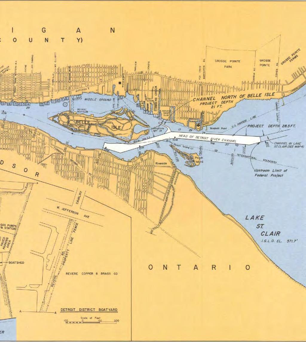
18 occurred in the mid 1930's following the completion of the 25-foot channel. Construction of the new St. Clair cut-off channel ( ) and further deepening of the channel to 27 feet also decreased the degree of ice retardation. This evidence indicates that the channel deepening resulted in more efficient channels for ice passage. Significant ice retardation events have occurred (April 1984) where record ice jams have reduced normal river flow by as much as 65%. B: Detroit River History The Detroit River (Figures 2a, 2b, 2c, 2d, 2e) is about 32 miles long from its head at the Windmill Point Light to its mouth at the Detroit River Light in Lake Erie. The fall in water level from Lake St. Clair to Lake Erie, is about three feet. The river is characterized by two distinct reaches. The upper reach extends downstream from Lake St. Clair to the head of Fighting Island, about 13 miles. As water flows out of Lake St. Clair, it divides as it passes Peach (Peche) Island. The channels on both sides of this island are relatively deep, but the main navigation channel from Lake St. Clair lies north of this island. Just below Peach Island lies Belle Isle. The main river channel, the Fleming Channel, runs to the south of this island. The channel north of Belle Isle is divided by the Scott Middle Ground, with depths varying from 1 to 6 feet. The channels on either side of the Scott Middle Ground are quite deep (19 to 30 feet), but are only used by small craft. 12
19 2a 13
20 2b 14
21 2c 15
22 2d 16

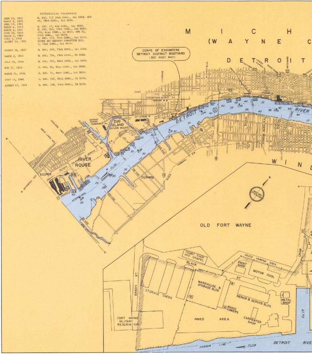
23 2e FIGURE 2a Thru 2e: Official Project Map of the Detroit River 17
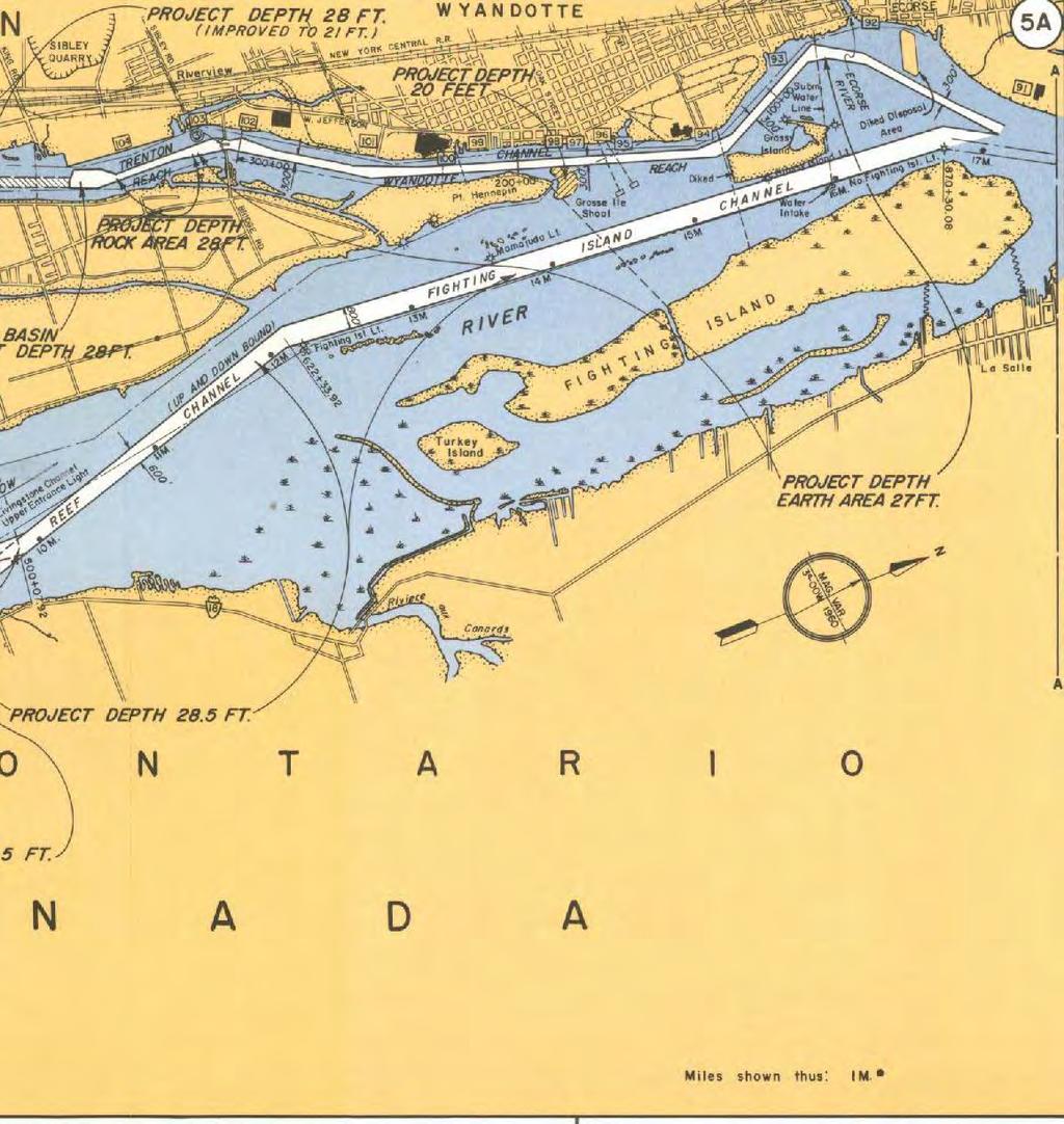
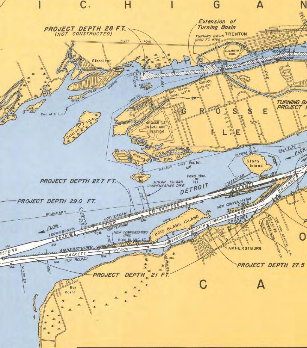
24 From the foot of Belle Isle to the head of Fighting Island, the channel is generally broad and deep. Its bottom consists of sand and clay and its banks are quite steep. The river, in this reach, averages about 2,400 feet in width and has depths of 35 to 50 feet. The deepest areas are found in the vicinity of the Ambassador Bridge, where the river slightly narrows to a width of about 1,900 feet for a distance of 1-1/2 miles. The southerly or lower reach of the Detroit River is broad, with several islands and shallow expanses. In the upper part of this reach, the banks rise with a gentle slope and the bottom consists of sand, clay, boulders and rock. In the six mile stretch from just downstream of Fighting Island to the south end of Bois Blanc Island, the bottom is mainly bedrock and boulders. The natural formation of the lower river bed has required very extensive rock excavation and dredging to provide navigation channels of suitable width and depth for large vessels engaged in lake commerce. During high flow conditions, velocities in these channels vary from 2.5 to 5.5 feet per second, depending upon the configuration of specific cross-sections. At the head of Fighting Island, the river divides into three channels; east and west around the island and an extensive middle ground further to the west. The middle channel, known as the Fighting Island Channel, is the main navigation channel. The channel on the Canadian side is divided by Grass and Turkey Islands before it rejoins the main channel below Fighting Island. The west-most channel (along the U.S. shore), which was originally narrow and crooked, has been straightened by a cut across the upper end of the middle ground. This channel divides around Grosse Ile. The channel west of Grosse Ile is the Trenton Channel. The other channel rejoins the main (middle) channel at the foot of the middle ground. River depths at the south end of the Trenton Channel are less than 10 feet and do not permit navigation of deep-draft vessels. Turning basins in this channel allow deep-draft vessels to return into the Detroit River. The Trenton Channel below Gibraltar is divided by Celeron Island. Downstream of Fighting Island the river is broad and shallow, except in the navigation channel (the Ballards Reef Channel). About 1-3/4 miles below Fighting Island, this channel divides around Stony Island. To the east of Stony Island, the navigation channel splits (around dikes) into the Amherstburg and Livingstone Channels. The Amherstburg Channel, between Bois Blanc Island and the Canadian mainland, accommodates upbound traffic. The Livingstone Channel, west of Bois Blanc Island, accommodates downbound ship traffic. These two channels recombine below Bois Blanc Island as the river enters Lake Erie. Originally, the best channel for navigation, downstream of Fighting Island, lay along the Canadian shore. However, vessel draft was limited by a rock ledge extending east from Stony Island, at a depth of about 13 feet, known as the Limekiln Crossing. In 1876, the United States began removal of rock; securing depths, by 1886, of 20 feet over a width of 300 feet. From that time, improvement work has been almost continuous. In 1886, work began to widen the Limekiln Crossing Channel to 440 feet. This was completed in Between 1901 and 1904, this channel was widened to 600 feet. In 1887, construction began on a bridge between Belle Isle and the United States mainland. This bridge was completed in In 1915, the superstructure of the bridge was destroyed by fire and 18
25 was replaced by concrete arches. The bridge piers undoubtedly reduced the flow through the channel west of Belle Isle, but the effect upon the levels above is considered insignificant. As part of a 21-foot Great Lakes Ship Canal project, dredging began in 1894 to remove shoals from an area extending from the head of Ballards Reef to Limekiln Crossing, for a width of 800 feet and a depth of 21 feet. Also as part of this project, dredging was done to remove a bar at the mouth of the Detroit River ( ). By 1900, improvements had also been made in the Amherstburg Reach and Hackett Reach of the Amherstburg Channel and Grosse Pointe Flats to provide depths of 21 feet. In 1908, work was begun on the Livingstone Channel, in order to provide a separate downbound channel 300 feet wide and 24 feet deep. The channel was cut across the shallow water east of Stony Island and extended downstream and west of Bois Blanc Island to deep water in Lake Erie. The upper portion, about 6,000 feet in length, was enclosed by cofferdams and dewatered. When work was completed, in 1912, the cofferdams were left as a form of compensation. Openings were made at each end of the cofferdam enclosure, 300 feet in width. The openings were widened to 450 feet in Between 1920 and 1922, the Livingstone Channel was widened to 450 feet over its entire length. During the same period, the construction of a dike on the west side of the lower part of the channel and the dumping of dredged material was completed. Before the construction of the Livingstone Channel, little if any attention was given to the effect of channel improvements upon lake levels. However, all of the material excavated from one part of the river was dumped in other portions. This undoubtedly gave some compensation. There had also been some encroachment on the river by wharfs along the water front, and the extensive filling at the head and foot of Belle Isle, by the City of Detroit. Sherman Moore, with the U.S. Lake Survey District, Corps of Engineers, wrote in 1935 that"...it appears fairly certain that in spite of the large amount of dredging in the interests of navigation, including the breaching of the rock ledge at the Limekiln Crossing, there has been no measurable change in the capacity of the Detroit River as a whole between 1859 and While the capacity of the river as a whole has been unchanged, the capacity of certain reaches has been slightly increased while that of other reaches has been diminished...the capacity of the reach (from Stony Island to below Bois Blanc Island) has been increased while the capacity of the reach between Windmill Point and Fort Wayne has been reduced by filling above and below Belle Isle, and by encroachment of the dock lines at Detroit." A 24-foot Navigation Project was begun in This project required further deepening of the channels in the lower river and some dredging near the head of the river. To further deepen the Livingstone Channel, it was enclosed by a cofferdam from 1932 to In 1935, the upstream and downstream ends of the cofferdam were removed. The sides were left in place to compensate for the increased depth of the channel. An additional compensating dike, extending westerly from the west dike of the Livingstone Channel towards Sugar Island, was constructed in In 1940, the deepening of the Trenton Channel was begun. The project provided for a turning basin 1,700 feet downstream of the lower Grosse Ile Bridge and a 250 feet wide, 21 foot deep channel from the main navigation channel to the turning basin. In 1964, additional dredging was completed to provide for a 300 foot wide, 27 foot deep channel from the main navigation channel to the Upper Grosse Ile Bridge; and for a 300 foot wide, 28 foot deep channel extending about 6,000 feet 19
26 downstream of the bridge, to and including an upper turning basin 28 feet deep and 15 acres in area, outside the channel limits. Between 1957 and 1962, dredging was again done in the river, this time to accommodate a 27-foot Navigation Project. The majority of the work was done in the Amherstburg Channel. This work was completed in August To compensate for the additional channel capacity, two dikes were constructed. One dike was an enlargement of an existing dike at the junction of the Amherstburg/ Livingstone and Ballards Reef Channels. Construction of this dike was started in May 1957 and was completed in August The dike is along the west side of the Amherstburg Channel and extends 10,000 feet downstream of the Upper Entrance Light. The second dike was built downstream of the lower end of Bois Blanc Island, parallel to and 100 feet west of the Amherstburg Channel. The construction of this dike, 6,200 feet in length, was started in January 1958 and was completed in May Water depths in the river vary in accordance with the seasonal levels on Lakes St. Clair and Erie. Fluctuations of several feet, lasting over periods of several hours, can occur as a result of transient meteorologic phenomena. Such fluctuations at the mouth of the Detroit River are produced by high easterly or westerly winds, which cause the water levels to vacillate in Lake Erie. These changes have been as great as eight feet within a five-hour period (April 6, 1979), with a water surface slope of about 14.5 feet from one end of Lake Erie to the other end. Ice conditions in the Detroit River are considerably different from those in the St. Clair River. An ice bridge, or arch, usually develops in Lake St. Clair, across the head of the Detroit River, upstream of Peach Island. The ice bridge remains stable in the open lake and during periods of subfreezing temperatures, the edge of the ice bridge extends downstream to Peach Island, forming an ice arch on either side of the island. One exception is the broad and shallow passage between Belle Isle and the U.S. mainland. During periods of above freezing temperatures, the ice bridge erodes back into the Lake St. Clair and large sheets of ice begin to drift downstream into the upper Detroit River. If Lake Erie ice is fast or jammed in the lower end of the river, ice back-up results. Occasionally, during a prolonged warm spell, or an early spring breakup on Lake St. Clair, the entire river may fill with ice. The remainder of the upper river normally does not freeze over, due to its narrow channel and swift current. In the lower river, ice cover develops in the broad and shallow areas adjacent to the lower islands; nevertheless, the main navigation channels, particularly the Livingstone Channel, remain open as long as ice entering the channel can pass into Lake Erie. Ice in western Lake Erie is usually fast, but can shift in large sheets under the influence of prevailing winds. Westerly winds can create large areas of open water downstream of the Livingstone Channel, which can absorb most of the ice moving through the system. Easterly winds blow ice into the lower river and cause jams that can raise upstream levels and hamper navigation. Upstream flooding does not appear to be a serious problem, because the river banks are steep and most of the shoreline development was designed to tolerate the high levels that could result from occasional seiche effects on Lake Erie. Strong easterly winds temporarily raise western Lake Erie levels, which may exceed seven feet above chart datum. This condition has, on rare occasions and for short periods of time, actually reversed the direction of surface flow in the Detroit River. This was documented in 1986 by the NOAA Great Lakes Environmental Research Laboratory (GLERL) 20
27 from data recorded at an in-place current meter at the Fort Wayne section. At that time the meter indicated that the direction of flow had turned 180 degrees. C: Navigation Channel Design Criteria Both the St. Clair and Detroit Rivers have been maintained at various depths throughout the history of navigation on the Great Lakes. Due to improvements in vessel construction and the need to move more materials to support a growing population, vessels have become much larger and require deeper navigation channels for safe passage. The current authorized project at both the St. Clair and Detroit Rivers allows for 25.5 foot safe draft by vessels. The relationship between safe ship draft and depths are as follows: Primary consideration is given to clearance, squat, exposure to waves, and nature of the channel bottom. The clearance allowance varies from 0.5 feet in sheltered channels with soft bottoms to 2.5 feet in exposed channels with hard bottoms. A maximum allowance for squat of 2.0 feet is used in open river and lake channels. Thus the total allowance made for vessels underway varies from 1.5 to 4.5 feet (27 to 30 foot depth). II. St. Clair River Dredging History The following is a chronologic summary of construction and dredging in the St. Clair River. The years from 1852 to 1857 are referenced to calendar years. The rest are referenced to fiscal years (October September) for U.S. dredging projects and calendar years for Canadian projects St. Clair Flats: A survey began at the mouth of the south channel; little changes compared to a survey made 10 years earlier Improvements were proposed for the St. Clair Flats, south channel A chart of the St. Clair River was released, including soundings Operations commenced for the deepening of the channel through the St. Clair Flats: ft. wide, 14 ft. deep, excavated from the river channel to deep water in Lake St. Clair; 23,420 CY of material removed (final channel to be 250 ft. wide and 13 ft. deep) St. Clair Flats: Excavation was continued; width ranged from 170 ft. to 275 ft. (averaged 230 ft.), depth 13 ft; United States (Corps) started excavation, 125 ft. wide and ft. deep; Canada widened channel after U. S. ran out of funds; total amount of excavation 150,760 CY; excavation completed; width 230 ft. and depth 13 ft St. Clair Flats: Survey (soundings) taken of dredged channel St. Clair Flats: Complete departure from existing navigation channel; on March 2, 1867, Congress approved a plan of improvement for a new straight canal thru shoal; canal to be 300 ft. by 13 ft. by 1 1/2 mi., diked and banked 5 ft. above water St. Clair Flats Ship Canal: Work started; no estimates of dredged amounts available. 21
28 1869. St. Clair Flats Ship Canal: Dredged 4,320 lineal. ft. to full width and depth St. Clair Flats: Remaining work to be done is the leveling of the bottom of the canal to a uniform depth, at which time vessels will be allowed to pass through St. Clair Flats Ship Canal: Completed; opened on July 25, An extensive shoal existed at the mouth of the Black River in the St. Clair River; a project was adapted for dredging bar and middle ground to a depth of 15 ft In some places, effective depth had been reduced to 11-1/2 ft.; proposed additional dredging. Dredging at the mouth of the Black River commenced. Various river shoals were dredged to a 15 ft. depth Dredging at the mouth of the Black river continued. A total of 103,000 CY were dredged at this location during this and the previous year, and all the spoil was dumped in deep water below the bar. Entire River: Dredging was started on miscellaneous shoals to obtain a 16 ft. depth in a 200 ft. wide channel St. Clair Flats Ship Canal: Work to deepen the canal to 16 ft. and a 200 ft. width was nearly completed; 194,657 CY dredged St. Clair Flats Ship Canal: Dredging to 16 ft. depth completed; about 103,000 CY removed St. Clair River at the Mouth of the Black River: 67,000 CY removed from the middle ground under the appropriations made by the acts approved June 23, 1874 and March 3, The bar at the junction of the Pine and St. Clair Rivers was dredged Improvement of St. Clair River at the Mouth of the Black River: This work was closed on September 30, 1876, due to lack of funds Work at the mouth of the Black River completed; 257,200 CY excavated Improvement of St. Clair River at the Mouth of the Black River: Dredging of the Port Huron middle ground was completed to give 15 ft. soundings over it St. Clair Flats Canal: The expansion of the canal resulted in securing a channel 200 ft. wide with a depth of not less than 16 ft CY removed to restore the channel St. Clair Flats Canal: Some repairs were conducted to acquire a straight channel 200 ft. wide St. Clair Flats Canal: Some repairs were conducted to acquire a channel 200 ft. wide. 22
29 1883. St. Clair Flats Canal: Some work conducted to acquire a straight channel. The dikes on either side of the canal were formed of the material excavated from the channel. This material was deposited in large crib pockets made of timber. Lake sides of the dikes were protected by shorter sheet-pilings St. Clair Flats Canal: The condition of the superstructure was decayed and needed to be renewed; a single row of sheet-piling was insufficient and needed to be reinforced; the channel lakeward was gradually shoaling and needed to be improved by dredging St. Clair Flats Canal: Minor repairs were required; 4,282 CY removed during June St. Clair Flats Canal: Minor repairs involved in the operation and care of the canal were carried out; cavities in the dikes were filled with cedar bark, the willows growing on dikes were trimmed and planks were placed on the lake side of the dikes, the entire amount of dredging under contract was 64,580 CY, of which 60,298 CY were dredged during this Fiscal Year and 4,282 CY during June, Of the total amount dredged and removed, 7,546 CY were from the head of the canal and 57,034 from the foot St. Clair Flats Canal: The present plan for improving the canal contemplated driving a double row of sheet-piling to a depth of 26 ft. along the channel face of each dike, dredging the area between them to a depth of 20 ft., continuing the channel above and below the canal to the same depth as the river and lake and rebuilding the wooden superstructure. The necessity for this work was immediate and urgent St. Clair Flats Canal: Under an appropriation made by the River and Harbor Act of August 11, 1888, 4,082 lineal ft. of new sheet-piling had been placed in the Fiscal Year (project plan called for a channel bounded on each side by a dike 7,221 ft. long). It was expected that the funds available would be enough to complete about 8,200 lineal ft. and that this will be accomplished on or before December 1, 1889, making a total of about 10,700 lineal ft. of new work and leaving about 3,800 lineal ft. of new sheet-piling yet to be constructed. During the first days of September 1888, a "blockade" of vessels occurred at the canal due to vessel groundings, damaging vessels and the canal, requiring immediate restoration of the channel; 56,117 CY of material removed Redredged, at the mouth of the Black River, to a depth of 16 ft. About 46,000 CY removed Commercial sand dredging in the river dates back to calendar year 1890, when large quantities of sand were removed from the north channel downstream of Algonac, Michigan St. Clair Flats Canal: Under a contract dated November 28, 1890, 490 running ft. of revetment was completed; under another contract, dated November 28, 1890, 43,496 CY, scow measure, were excavated. On June 30, 1891, a channel 18 ft. in clear depth and 150 ft. wide extended from an 18 ft. curve in the St. Clair River, about 900 ft. above the canal, down into the 23
30 canal for a total length of about 3,890 ft.; the dredged channel occupied the east half of the northern part of the canal Dredging near the mouth of the Black River continued. During the calendar year about 57,500 CY removed On June 30, 1892, the pile revetment along the channel face of each dike was completed and a channel 18 ft. in clear depth extended from the 18 ft. curve in St. Clair River, about 900 ft. above the canal, for the full width of the canal (about 300 ft.) and throughout its entire length; thence gradually widening to 380 ft. in a distance of 300 ft. below the canal, thence with a width of 380 ft. for a further distance of 2,400 ft. Dredging was continued during the Fiscal Year until July 15, About 153,000 CY removed since July Redredging at the mouth of the Black River, continued in the fall, completing the dredging all over the shoal to 16 ft. and to 18 ft. on the easterly border. About 42,000 CY removed St. Clair Flats Canal: On June 30, 1893, a channel, 18 ft. in depth, extended from the 18 ft. curve in the St. Clair River, about 900 ft. above the canal, for the full width of the canal (about 300 ft.) and throughout its entire length; thence gradually widening to 380 ft. at a distance of 300 ft. below the canal, thence with a width of 380 ft. a further distance of 3,300 ft St. Clair Flats Canal: No work was done during the Fiscal Year and conditions remained as stated in the previous year (portions of timber superstructure decayed). During October 1893, damage done to the east and west dikes by steamers was repaired Near the mouth of the Black River. No exact details on quantities, apparently 1,200 to 1,500 CY removed Above the Head of the St. Clair River: A 2,400 ft. by 21 ft. channel over a length of about 8,000 ft. was nearly completed; east 1/2 completed and opened to navigation (prior to Fiscal Year 1897, 483,882 CY, scow measure, removed); west 1/2 nearly completed (December 1892-September 1896, total 483,536 CY, scow measure, removed) Point Edward: A bar in front of the Grand Trunk Railroad elevator was dredged in August, 5,800 CY removed Redredging at the mouth of the Black River started in June 1897; 729 CY excavated Point Edward: Dredging of bar in front of Grand Trunk Railroad elevator, 8,500 CY removed Middle Ground Shoal St. Clair: 45,729 CY excavated to restore 16 ft. depth; 55,579 CY excavated to eliminate sharp bend in ship channel and to increase the width from 750 ft. to 1500 ft. 24
31 1899. Removal of Shoals Near Stag Island: 44,636 CY excavated to obtain a clear channel 20 ft. deep St. Clair Flats Canal: 17 ft. shoal at lower approach removed; 15,395 CY dredged Squirrel Island and Grand Pt: Shoals removed; 16,003 CY dredged Stag Island: Series of shoals near foot of island removed; 44,860 CY (clay, sand and small stones) dredged On August 4, 1900, the steamer Fontana was wrecked in the narrows at the head of the river. On September 22, 1900, the steamer Martin was wrecked at the same location St. Clair Middle Ground: 12,274 CY removed Lower End of Stag Island: 51,481 CY removed Grande Pointe: 22,998 CY removed Lower Approach to the St. Clair Flats Canal: 28,806 CY of sand and clay removed St. Clair Flats Canal Lower Entrance: 60,997 CY removed, increasing channel width from 80 to 200 ft Middle Ground Shoal Opposite the Mouth of Black River, Port Huron: 82,569 CY removed Lower Approach to the St. Clair Flats Canal and the Arthur House Shoal: 47,663 CY removed Squirrel Island, St. Clair, Middle Ground and Stag Island: 352,517 CY of material excavated Lower End of Lake Huron: 60,512 CY removed Point Edward: A cut was made along the Grand Trunk Railroad dock and freight shed, 23,900 CY removed. Some dredging was done at the approach to the dock, but no quantities given Construction of a Second Channel from Lake St. Clair up into St. Clair River: At the end of the Fiscal Year, the new channel had been dredged to a width of 150 ft. and a depth of 18 ft. for a length of 4,317 ft.; 2,558 ft. of pier revetment had been built Grosse Point Cut and Lower Approach to the St. Clair Flats Canal: 56,936 CY removed. 25
32 1905. Point Edward: Dredging of a channel 200 ft. wide and 22 ft. deep in front of the docks was initiated; 79,500 CY removed. The approach to the Point Edward and Sarnia Bay Lumber Company s docks was dredged, 29,400 CY removed Sarnia: Dredging along the front of the Imperial Oil Company s docks, 9,000 CY removed Construction of Second Channel: Work continued; since commencing a contract on July 15, 1904, the upper pierhead and 7,146 lineal ft. of revetment have been built and 1,261,237 CY of material excavated. Some dredged material was deposited to form dykes on each side of the cut behind steel sheet pile Point Edward: Work resumed on dredging a channel in front of the docks; 65,500 CY removed Sarnia: Dredging opposite the Imperial Oil Company dock, and in front of and between the docks of the Sarnia Bay Lumber company and the Cleveland-Sarnia Sawmill Company, all to a depth of 15 ft., 17,000 CY removed Point Edward: Dredging in front of the docks, and between the docks and deep water, 298,000 CY removed Construction of Second Channel: Work completed on October 17, During the Fiscal Year, the lower pierhead and 74 lineal ft. of revetment were built and 783,564 CY of material excavated. The dredged material was deposited to form dykes on each side of the cut At the mouth of the Black River and along the dock front at Port Huron: From May to August 23,500 CY removed to restore a depth of 16 ft. From August to October 22,500 CY removed between Military Street and the Michigan Sulphite Fibre Works to restore the 16 ft. channel Point Edward: In front of the docks and further out in that vicinity, 151,000 CY removed Sarnia: Two shoals in the river were dredged, 21,000 CY removed In calendar year 1908, commercial interests began to remove sand and gravel from the head of the river (between 1909 and 1925 about 3-1/2 million CY of material were removed, most above the Dry Dock gauge; see 1925) Point Edward and Sarnia: Dredging to 22 ft. for a distance of 3,700 ft. and on the Point Edward dock frontage, and to depth of 16 ft. opposite the area between the Cleveland-Sarnia and the Sarnia Lumber docks, 82,000 CY removed A survey was conducted of the shoal in the St. Clair River opposite Port Huron, Michigan. 26
33 1910. Point Edward: Dredging to deepen the approach to the lumber docks, 6,000 CY removed Sarnia: Approach to Sarnia docks was deepened, 27,400 CY removed. Obstructions in front of Imperial Oil and Pere Marquette docks were removed, 3,100 CY removed The governments of Canada and Ontario agreed to permit commercial sand and gravel dredging from the St. Clair River at Point Edward. The permits allowed the taking of such material as would otherwise have to be removed in order to maintain a sufficient depth of water opposite the Point Edward docks, but dredging deeper than 23 ft. was prohibited Point Edward: Cadwell Sand and Gravel removed cargoes of sand and gravel, size of cargo not given Surveys were conducted in the St. Clair River opposite Grande Pointe, and in Lake St. Clair from the head of the St. Clair Flats Canal to the lower end of the Grosse Pointe Channel, and an examination was made of the channel at the foot of Lake Huron Chenal Ecarté: Dredging at Johnston s Bend and Muldoon s Bend to 19 ft., 41,000 CY removed; dredging at the mouth to 10 ft., 16,000 CY removed A survey was made of the shoal at the foot of Lake Huron, and examinations were made of sections in the St. Clair River St. Clair Flats Canal: 8,456 tons of stone were placed on and around piers. The east pier had been riprapped on the east side for its entire length with rubblestone The Province of Ontario approved regulations that authorized the licensing of removal of sand and gravel from the beds of rivers and lakes Point Edward and Sarnia: Cadwell Sand and Gravel Company removed 50,500 CY; dredging of the channel to the outer end of the pier of the Cleveland and Sarnia Saw Mills company, 1,200 CY removed; dredging of channel fronting new pier of Imperial Oil company, 14,650 CY removed Point Edward: Cadwell Sand and Gravel Company dredged sand and gravel in front of the Grand Trunk Railroad dock, 66,300 CY removed Sarnia: Dredging from shoals in front of Pere Marquette and Imperial Oil Company docks, 14,900 CY removed Point Edward: Cadwell Sand and Gravel Company dredged sand and gravel, 51,000 CY removed; Canadian Public Works department dredged shoal adjacent to Northern Navigation docks and from opposite other docks, 41,000 CY removed Sarnia: Dredging from shoal fronting Imperial Oil dock, 4,400 CY removed; dredging from shoal opposite and adjacent to Reid s dock, 27,000 CY removed. 27
34 1915. Ship Channel in Lake St. Clair at and Below St. Clair Flats Canal: Removed 36,993 CY, scow measurement, of shoaled material for restoration of project depths (20 ft.) and nearly to project width (300 ft.) of the east or upbound channel; 30% of work completed Point Edward: Cadwell Sand and Gravel Company dredged sand and gravel from an area about 3,000 X 170 ft. in front of Point Edward, 44,000 CY removed Sarnia: Dredging of an 1,100 ft. long channel 12 ft. deep from deep water to the Cleveland-Sarnia Saw Mill dock, 14,500 CY removed Port Huron: A portion of 2,400 CY dredged from the Black River was placed in the St. Clair River below the line of the St. Clair tunnel Ship Channel in Lake St. Clair at and Below St. Clair Flats Canal: Work in progress at the end of Fiscal Year 1915 was continued and completed in September 1915; a total of 160,442 CY removed (deposited in Lake St. Clair), 123,449 CY during Fiscal Year; dredging resumed in April 1916, at close of year, a total of 231,796 CY had been removed In its annual report, the Ontario Bureau of Mines reported that sand and gravel were removed from the bed of the St. Clair River for commercial purposes, but the quantity was not recorded Point Edward and Sarnia: Several companies dredged sand and gravel from the river opposite Cromwell Street, 130,000 CY removed. It was noted that strong current and storms on Lake Huron wash sand and gravel into the mouth of the St. Clair River, making dredging necessary each year. There was a verbal agreement between staff of the two federal governments that neither would permit dredging upstream of the tunnel to a depth of greater than 23 ft Sarnia: Dredged channel in Sarnia Bay to and along wharves of Dominion Salt Co. and the Cleveland-Sarnia Saw Mills Co., 7,100 CY removed Point Edward and Sarnia: Agreement with Chick Contracting Company to maintain a 21 ft. depth opposite the wharves at Point Edward and all areas where shoals might form in the Canadian section of the river between Michigan Avenue, Sarnia and the tunnel, 173,000 CY removed; other companies removed 179,600 CY under license between the tunnel and Stag Island Black River Shoal: Removed between calendar years Port Huron Shoal West Channel: Removed 323,463 CY of mainly sand and clay. A foundation for the submerged weir was formed by depositing dredged material St. Clair Flats: Dredging to restore project depths in the canal and its lower approaches, 62,000 CY removed. 28
35 1922. Port Huron Shoal West Channel: Removed 4,877 CY, scow measure, of mainly sand and clay; between April 6 and 17, 1922, on east side of channel, removed 25,560 CY, bin measure, of sand, gravel and silt; on April 13, 1922, at the foot of Lake Huron, removed 1,120 CY, bin measure, of sand and gravel Reconstruction of East Dike at St. Clair Flats Canal: 108,990 CY removed, work completed October 31, Port Huron Middle Ground Shoal: Removed 62,094 CY, scow measure, of material Province of Ontario reported 289,358 CY of gravel was removed from the St. Clair River for commercial purposes. Sand removal probably also occurred, but was not quantified, or might have been included. Canadian Public Works reported that 157,000 CY of sand and gravel was removed at Point Edward. There may be some duplication in the two quantities given above Middle Ground Shoal: Removed 287,328 CY, scow measure, of material Port Huron West Channel and Middle Ground Shoal: Removed 46,987 CY, bin measure, of scattered shoals of sand, gravel and silt Foot of Lake Huron: Removed shoaling from channel, to the extent of 95,416 CY, bin measure St. Clair Flats: Re-dredging of the lower part of the canal and approaches, 49,000 CY removed Middle Ground Shoal: Removed 44,929 CY, sand, gravel and silt, used for commercial purposes St. Clair Flats Canals: Dredged to restore project depths, 56,351 CY removed Province of Ontario reported: 56,040 CY removed north and south of international tunnel; 123,154 CY removed north of international tunnel; 116,592 CY removed south of international tunnel, sand and gravel for commercial purposes Middle Ground Shoal: Removed 54,075 CY of material, used for commercial purposes; additional 42,959 CY, bin measurement, removed from a channel length of about 4,000 ft Lower End of Lake Huron, East Half of 800-ft. Channel: Excavated 212,477 CY, place measurement, for length of about 2 miles Shoals Removal and Deepening of West Half of Channel: Removed 93,168 CY, scow measurement, within a channel length of about 5,500 ft Head of Russell Island: Removed 163,700 CY of material. 29
36 1925. Province of Ontario reported 276,848 CY removed north and south of international tunnel, sand and gravel for commercial purposes Point Edward: Records of the Province of Ontario show that 1,519,000 CY has been dredged since 1910 under their permits. A survey of the area was conducted, and it showed an apparent removal of 2,400,000 CY In calendar year 1925, sand and gravel dredging was prohibited in the United States waters Beginning in 1926, the Ontario Department of Mines reported that it would permit sand and gravel dredging north of the international tunnel only if the Government of Canada authorized it as being necessary for navigation Lower End of Lake Huron: Shoals removed from east half of 800-ft. channel for length of about 2 miles completed, west half of channel maintenance dredging completed, 359,944 CY, scow measurement, removed in Fiscal Year Head of Russell Island: Removed 8,860 CY of shoal material, place measurement Province of Ontario reported: 61,700 CY removed north of international tunnel; and 32,353 CY removed south of international tunnel, sand and gravel for commercial purposes Province of Ontario reported: 118,667 CY removed near international tunnel; and 14,685 CY removed south of international tunnel, sand and gravel for commercial purposes Province of Ontario reported: 83,574 CY removed north of international tunnel; 17,791 CY removed south of international tunnel; 19,667 CY removed at light #5 almost opposite Tashmoo Park, opposite Squirrel Island, upstream from southeast bend, sand and gravel for commercial purposes Province of Ontario reported: 78,705 CY removed north of international tunnel; 15,545 CY removed at Sarnia Bay elevator slip; 200 CY removed south of international tunnel; 83,748 CY removed at Squirrel Island; 2,947 CY removed off Squirrel Island, ½ mile upstream of southeast bend Light #5 and opposite Tashmoo Park, sand and gravel for commercial purposes Westerly Edge of Downbound Channel at Port Huron, Michigan: Removed 79,284 CY, bin measure Province of Ontario reported: 62,917 CY removed north of international tunnel; 5,720 CY removed at head of Stag Island; 346,342 CY removed at Squirrel Island; 81,082 CY removed west of Chematogan Channel Squirrel Island, sand and gravel for commercial purposes Westerly Edge of Downbound Channel at Port Huron, Michigan: Removed 61,937 CY, bin measure. 30
37 1931. Shoal at Roberts Landing: Removed 120,721 CY, bin measure Province of Ontario reported: 38,685 CY removed north of international tunnel; 8,064 CY removed at head of Stag Island; 2,700 CY removed at Squirrel Island; 1,554 CY removed at northeast point of Squirrel Island, sand and gravel for commercial purposes Sand and gravel dredged by private parties under permits Province of Ontario reported: 1,730 CY removed at head of Stag Island; 20,889 CY removed northeast of Squirrel Island 4,769 CY removed at Southeast Bend light #5 and upstream one mile; 1,054 CY removed northeast of Squirrel Island extending downstream ½ mile, sand and gravel for commercial purposes Dredging to present project depth was done at the foot of Lake Huron; 198,052 CY, place measure, removed. Dredging for a 25 ft. deep navigation channel began in June 1933 and was completed in October Province of Ontario reported: 3,077 CY removed in area of Stag Island; 700 CY removed in Squirrel Island Walpole area; 6,470 CY removed northeast of Squirrel Island and opposite Walpole Island, sand and gravel for commercial purposes Surveys were made and studies were continued with the view of placing submerged weirs at the head of the river to provide compensation for channel deepening Foot of Lake Huron: Dredging under a continuing contract was discontinued on November 2, 1933; a total of 1,132,240 CY, place measure, removed from the shoal; contract was about 64% completed Roberts Landing Shoal: 963,383 CY, bin measure, removed between October 11 and November 30, 1933; work about 30% completed South Channel: 2,220,032 CY, bin measure, removed; work about 99% completed St. Clair to Marysville: 17,633 CY, place measure, removed; contract about 1% completed Marine City Shoal: Contract was started on April 19, 1934 and finished on May 16, A channel having a least depth of 25 ft. and a minimum width of 1,000 ft. was in existence at this locality Head of Russell Island Shoal: Contract dredging was started on October 21, 1933, discontinued for the season on December 23, 1933, resumed on April 5, 1934 and discontinued on May 19, 1934; a total of 214,533 CY, place measure, removed; contract about 67% completed. 31
38 1934. Channel Above St. Clair Flats Canal: Dredging in this area was included in the contract for the removal of the west dike and deepening of the east and west channels Province of Ontario reported: 23,183 CY removed north of international tunnel; 7,313 CY removed in area of Stag Island, sand and gravel for commercial purposes Foot of Lake Huron: Dredging started on June 14, 1933, and was completed on September 16, 1934; the total amount of material removed under this contract was 1,682,560 CY, place measure Marysville to Port Huron: Removed 220,449 CY, place measure St. Clair to Marysville: Removed 1,472,820 CY, place measure Roberts Landing Shoal: Dredging by the U.S. sea-going hopper dredge Meade, during the period from August 23 to October 18, 1934, during which time this dredge removed 409,023 CY, bin measure; dredging by the U.S. sea-going hopper dredge Taylor, during the period from September 24 to December 10, removed 908,176 CY, bin measure Marine City Shoal: Removed 212,392 CY, place measure Head of Russell Island: Contract dredging started on October 21, 1933 and was completed on September 5, 1934; the total amount of material removed was 309,479 CY, place measure Channel Above St. Clair Flats Canal: Dredging in this area was included in the contract for removal of the west dike and deepening of the east and west channels Province of Ontario reported: 540 CY removed north of international tunnel; 79,637 CY removed at Stag Island, sand and gravel for commercial purposes Roberts Landing Shoal: 214,948 CY of shoal material, bin measure, removed Marysville to Port Huron: Contract dredging in this section of the river was started October 5, 1934 and was completed on March 30, 1936; total quantity removed under this contract amounted to 950,822 CY of shoal material, place measure St. Clair to Marysville: Contract dredging over this area started May 26, 1934 and was completed November 8, 1935; total quantity removed under the contract amounted to 1,623,603 CY, place measure Roberts Landing Shoal: Submarine grading contract started October 10, 1935 and was completed December 3, 1935; the total area graded amounted to 390,433 sq. yds St. Clair to Port Huron: 915 CY of boulders and wreck of an old steamer removed. 32
39 1937. Roberts Landing Shoal: 34,496 CY, bin measure, removed Province of Ontario reported: 5,679 CY removed in front of fish hatchery at Point Edward; 22,977 CY removed north of international tunnel; 900 CY removed at Squirrel Island, sand and gravel for commercial purposes Upbound Channel East of Stag Island Near the Lower End of Island: 14,315 CY of boulders, gravel and clay, bin measure, removed; work completed November 1, Province of Ontario reported: 3,332 CY removed opposite Point Edward; 68,175 CY removed at Stag Island (might have been removed from Island), sand and gravel for commercial purposes Shoal Opposite the Mouth of Black River: 22,012 CY, bin measure, removed Shoals in the Lower St. Clair River: 93,119 CY removed Province of Ontario reported: 29,193 CY removed near Point Edward, sand and gravel for commercial purposes Lower St. Clair River: 235,832 CY, bin measure, removed from shoals Province of Ontario reported: 45,362 CY removed at Point Edward, sand and gravel for commercial purposes Lower St. Clair River: 156,813 CY, bin measure, removed from shoals Upper St. Clair River: 10,790 CY, bin measure, removed from shoals St. Clair Flats Canal: Maintenance shoal removal, 129,637 CY Province of Ontario reported: 2,869 CY removed at Point Edward, sand and gravel for commercial purposes Lower St. Clair River: 270,635 CY, bin measure, removed from shoals Upper St. Clair River at the Mouth of the Black River: 21,879 CY, bin measure, removed from shoals Lower St. Clair River: 52,648 CY, bin measure, removed form the Russell Island Shoal Canadian Side of the Southeast Bend: Under contract, dated August 24, 1942, 244,138 CY, pay place measure removed; work completed November 11, Province of Ontario reported: 3,993 CY removed at Point Edward, sand and gravel for commercial purposes. 33
40 1944. Channel at the Foot of Lake Huron: 236,710 CY, bin measure, removed South Channel: 108,437 CY, bin measure, removed; dredging completed Obstructions removed from the Southeast Bend Southeast Bend: 105,567 CY, bin measure, removed Stag Island: dredging at north end for commercial purposes, amount unknown Stag Island: Shoals removed in up-bound channel; 19,738 CY, bin measure, removed Head of Russell Island: 49,239 CY, bin measure, of shoals removed Foot of Lake Huron: 12,984 CY, bin measure, of shoals removed Mouth of the Black River: 67,044 CY, bin measure, removed Opposite Black River, on Canadian side: authorization was given for removal in 1949 and 1950 of up to 30,000 CY for commercial purposes, actual amount unknown South Bend: 45,888 CY, bin measure, of shoal material removed Russell Island and Grande Pointe to Squirrel Island: 135,486 CY, bin measure, of shoal material removed Commercial sand and gravel dredged Southeast Bend Channel: 124,277 CY, bin measure, removed St. Clair Flats Channel: 210,965 CY of shoal material removed Shoals at the mouth of the Black River, head of Russell Island, Squirrel Island and Grande Pointe were removed in the amount of 133,299 CY, bin measure Dredging for the 27 ft. deep navigation channel began Foot of Lake Huron Channel: 183,587 CY of clay removed Foot of Lake Huron Channel: Work continued Dredging for the 27 ft. deep St. Clair River Cutoff channel began in April 1960 and was completed in
41 1961. Two contracts awarded for deepening the channel from Stag Island to Marine City and from Algonac to the Southeast Bend reach Deepening at the Foot of Lake Huron Channel: Project completed, dredged 330,656 CY of clay Channel from Port Huron to Stag Island: Deepened to a project depth of 27.4 ft.; 42,354 CY and 377,100 sq. yds. (uniform depth) of gravel and clay dredged with a clamshell; project completed Stag Island: Channel deepened to a project depth of 27.3 ft.; 697,425 CY of clay and sand removed Project to Remove Shoals from Russell Island to the Southeast Bend Cut-off Channel: 143,000 CY of sand removed The work of deepening the Southeast Bend Cut-off Channel continued Foot of Lake Huron Channel: 12,500 CY removed; project completed Channel from Port Huron to Stag Island: 107,003 sq. yds. of miscellaneous shoals removed; project completed Stag Island: 17,604 CY of clay and sand removed, contract work completed; 484,244 sq. yds. (uniformed depth) of shoals removed by hired labor (plant operated by the U.S. Government), work to be continued next year Deepening the Channel Between Stag Island and Southeast Bend: 372,551 CY of clay and sand removed under the contract; work completed The removal of miscellaneous shoals was continued; 313,618 CY of sand and clay removed Southeast Bend Channel: Dredged sand and clay to a project depth of 27.1 ft., under the contract; 7,740 CY dredged by hired labor (plant operated by the U.S. Government); work completed Channel at Stag Island: 1,200 CY of sand and clay removed with leveling of dump ground Stag Island to Southeast Bend: 91,928 CY of sand, clay and gravel removed Hydraulic model studies for compensating works was initiated by the Waterways Experiment Station, Vicksburg, Mississippi Hydraulic model studies for compensating works continued. 35
42 1964. Stag Island to Southeast Bend: 29,775 CY, scow measure, of sand and clay removed, along with sunken vessels and obstructions Channel Near Port Huron and Between Stag Island and Southeast Bend: 22,575 CY, scow measure, removed Maintenance Dredging Over Various Areas: 174,506 CY of shoal material, bin measure, removed Hydraulic model studies for compensating works continued Maintenance Dredging Over Various Areas: 93,957 CY of shoal material, bin measure, removed Dredging by Shell Canada of 4,120 CY Hydraulic model studies for compensating works continued Maintenance Dredging Over Various Areas: 205,056 CY, bin measure, and 48,150 CY, scow measure, removed Hydraulic model studies for compensating works continued Maintenance Dredging: 129,966 CY of shoal material, bin measure, removed Hydraulic model studies for compensating works continued Maintenance Dredging: 121,434 CY of shoal material, bin measure, removed Dredging by Ontario Hydro near Courtright of 36,000 CY Maintenance Dredging: 131,664 CY of shoal material, bin measure, removed; obstructions were located and removed Channel modifications to accommodate larger Great Lakes vessels under construction and minor design studies for compensating works continued Maintenance Dredging: 129,221 CY of shoal material, bin measure, removed; obstructions located and removed Model study for the compensating works completed Maintenance Dredging: 155,578 CY of shoal material removed; obstructions located and removed. 36
43 1972. Maintenance Dredging: 26,337 CY removed; obstructions located and removed Maintenance Dredging: 8,800 CY of shoal material, scow measure, removed; obstruction located and removed Maintenance Dredging: 51,949 CY of shoal material, bin measure, removed; obstructions located and removed Maintenance Dredging: 54,512 CY of shoal material, bin measure, removed; obstructions located and removed Maintenance Dredging: 25,343 CY of shoal material, bin measure, removed; obstructions located and removed Maintenance Dredging: 12,155 CY of shoal material, bin measure, removed Disposal area facilities at Harsens Island constructed Maintenance Dredging: 24,803 CY of shoal material, bin measure, removed; obstructions located and removed Maintenance Dredging: 86,926 CY of shoal material, bin measure, removed; obstructions located and removed Maintenance Dredging: 22,076 CY, bin measure, removed Maintenance Dredging: 27,696 CY of shoal material, bin measure, removed Extended navigation season environmental studies performed Located and removed obstructions Maintenance Dredging: 37,564 CY of shoal material, bin measure, removed Extended navigation season environmental studies continued Maintenance Dredging: 106,973 CY, bin measure, removed Operated booster pump in connection with dredging Located and removed obstructions Extended navigation season environmental studies continued Maintenance Dredging at the Foot of Lake Huron: 71,795 CY of shoal material, bin measure, removed. 37
44 1984. Located and removed obstructions Extended navigation season environmental studies continued Located and removed obstructions Maintenance Dredging: 71,629 CY removed; works completed Located and removed obstructions Continue to locate and remove obstructions Maintenance Dredging: 92,233 CY removed Continued to locate and remove obstructions Maintenance Dredging: 193,160 CY removed; work completed Continued to locate and remove obstructions Continued to locate and remove obstructions Maintenance Dredging at Point Edward, Blue Water and Lower River: 16,500 CY removed Continued to locate and remove obstructions Contract for Maintenance Dredging was awarded: 68,187 CY of shoal material was removed; contract 67% completed Continued to locate and remove obstructions Continued to locate and remove obstructions A contract was awarded for maintenance dredging of the Outer Channel. Dredging to begin next Fiscal Year Mobilization for beach nourishment in conjunction with maintenance dredging was performed Continued to locate and remove obstructions Continued to locate and remove obstructions Continued to locate and remove obstructions. 38
45 1997. Continued to locate and remove obstructions Continued to locate and remove obstructions Continued to locate and remove obstructions A contract for maintenance dredging was awarded this FY. Dredging will begin next FY The contract awarded last year was complete this FY for maintenance dredging, removing 110,600 cubic yards of shoal material Continued to locate and remove obstructions Continued to locate and remove obstructions A contract for maintenance dredging was awarded. Contract was 44% complete at the end of the FY, removing 23,500 cubic yards of shoal material The contract awarded last FY for maintenance dredging was completed, removing 15,772 cubic yards of shoal material. III. Detroit River Dredging History The following is a chronologic summary of construction and dredging in the Detroit River. All years are referenced to fiscal years (October September) Approval was given to remove boulders and rocks from the river. The objective of this project was to create a curved channel 300 ft. wide and 20 ft. deep across a bed of limestone at Limekiln Crossing, which had a natural depth of only 13 ft A survey of the river in the vicinity of Limekiln Crossing was made by Canada; the results were furnished to the United States. The United States and Canada agreed to unite to remove obstructions from the Detroit River at specific places. About 120 CY of rock removed by Canadian government at Limekiln Crossing There was no reply from the Canadian government to join the U.S. in the removal of obstructions at the Limekiln Crossing; as such, operations were limited Work began in September 1876, in the shallowest portion of Limekiln Crossing; 2,632 CY of rock excavated; funds exhausted Nothing was done by the United States; no funds. Canada carried out some dredging at Limekiln Crossing. 39
46 1879. Limekiln Crossing: Drilling and blasting were done over an area of 90,000 sq. ft. containing 7,134 CY of rock, prism measurement; 3,262 CY of this material removed Limekiln Crossing: As of June 30, 1880, a total of 8,401 CY of material removed Limekiln Crossing: Dredging continued; 13,261 CY removed Limekiln Crossing: Dredging continued; 10, 469 CY removed. In May 1882, due to a lack of funds, the project was stopped Limekiln Crossing: The project was modified to provide a straight channel 300 ft. wide, utilizing much of the work already done; 6,534 CY of rock removed Limekiln Crossing: 656 CY of rock removed Limekiln Crossing: 8,401 CY of material removed Limekiln Crossing: The 1874 project was further modified; its width was to be increased to 400 ft. by removing an additional 100 ft. from the western (American) side Limekiln Crossing: The original 300 ft. channel was completed and an additional width of 50 ft. was removed from the western side for nearly the whole extent of the project During the calendar year 1887, construction began on the bridge between Belle Isle and the United States mainland Limekiln Crossing: The project continued until September 15, 1989, when it was suspended, due to the exhaustion of available funds Limekiln Crossing: The project was further modified; an additional width of 40 ft. on the western side was authorized; drilling and blasting continued; 8,508 CY of solid rock and 30 yds. of loose rock removed Belle Isle Bridge: Construction completed, during calendar year to Limekiln Crossing: The canal was completed to a depth of 20 feet and a width of 440 ft.; some shoals in the vicinity were removed to the same depth; 1,213 CY of solid rock and 1,584 CY of loose rock removed; range lights were established by the U.S. and Canadian governments to mark the completed channel The need for a project to remove shoals from the head of Ballards Reef to the head of Limekiln Crossing to a depth of 20 ft. and a width of 800 ft. was acknowledged Bar at Mouth of Detroit River: Between December 1892 and June 1896, 970,769 CY, scow measure, removed (mostly sand, clay, gravel and boulders) 40
47 1892 to Amherstburg: Dredging along the front of the village docks, under 10,000 CY removed A survey was conducted to determine the location and extent of obstructions between the head of Ballards Reef and the head of Limekiln Crossing; obstructions found consisted of bedrock and boulders Hackett Range: Work began on a channel 21 ft. deep by 600 ft. wide Grosse Pointe Flats: Between December 1892 and June 1896, 4,330,951 CY of material, mostly clay, gravel, sand and boulders removed During calendar year 1894, dredging began to remove shoals from an area extending from the head of Ballards Reef to Limekiln Crossing, for a width of 800 ft. and a depth of 21 ft Amherstburg: Dredging along the village docks, 8,000 CY removed. Additional dredging along the docks and on the New York shoal, 12,000 CY removed to Shoal near Ballards Reef: 16,097 CY, scow measure, removed Amherstburg: Dredging near Mullen s dock, 8,000 CY removed Grosse Pointe Flats: 1,219,258 CY of material removed (mostly clay, gravel, sand and boulders); a channel 20, 000 ft. long, 800 ft. wide and 20 ft. deep was completed Bar at Mouth of Detroit River: 40,354 CY, scow measure, removed (sand, clay, gravel and boulders). Many projections remain to be cleared Ballards Reef: East half of channel, 3,661 CY of boulders removed; west half of channel, 1,513 tons of boulders and bedrock removed to a depth of 21 ft Sandwich: Dredging at Cuddy-Mullen dock, 2,600 CY removed Grosse Isle Lower Range: The objective was to clear a channel to a depth of 21 ft. and a width of 600 ft.; east side of range area, width 150 ft., length 6,200 ft. and depth 20 ft.; 4,528 CY plus 12,946 tons of material removed Amherstburg Reach: The objective was to clear a channel to a width of 400 ft. and a depth of 21 ft.; east half of channel, 200 ft. by 1400 ft., depth 18 ft.; 5,523 CY of sand, clay, boulders, some limestone and bedrock, removed; partially cleared to a 21 ft. depth, 726 tons of boulders removed Hackett Range: Work began in 1893 and was completed in October 1897; during the Fiscal Year, 82,793 CY of material (clay, gravel, boulders and loose stone) removed. 41
48 1898. Limekiln Crossing: The depth was improved from 18 ft. to 19 ft. for a width of 440 ft.; 583 tons of boulders and loose stone removed Ballards Reef: 10,855 tons removed from the east side of the range line and from bedrock shoal (150 ft. wide by 250 ft. long) 300 ft. west of range lights. Work in the east channel was completed in October Amherstburg: Dredging at several locations, 6,000 CY removed Grosse Isle Lower Range: 11,815 tons of rock and boulders and 55,456 CY, scow measure, of clay, gravel, boulders and stone were removed from the east half of the channel between Ballards Reef Light and Duff and Gatfield's Dock, giving a clear channel 20 ft. by 300 ft. through the Ballards Reef Section for a length of 10,000 ft.. To obtain a 21 ft. depth, scattered bedrock and boulders remained to be removed Amherstburg Reach: The channel depth was increased to 19-1/2 ft., length 2,250 ft.; 14,245 CY of sand, clay, gravel, boulders, some limestone and bedrock removed Lower Detroit River: 800 tons of material (1,700 boulders) were removed from the Limekiln Crossing, Amherstburg Reach and Hackett Range. The reach below Limekiln Crossing to the south end of Bois Blanc Island was still limited to a depth of 18 ft North End of Limekiln Crossing to South End of Bois Blanc Island: 362 CY of boulders removed; channel below Limekiln Crossing to south of Bois Blanc Island still at 18 ft Grosse Isle Lower Range (south channel range, head of Ballards Reef to Limekiln Crossing, (21 ft. by 300 ft. by 12,000 ft.): 13,771 CY removed under contract; an additional 10,134 CY removed by hired labor (plant operated by the U.S. Government), plus 2,147 CY of boulders removed; work was completed in October 1899; total excavation 84,045 CY, scow measure, of material Limekiln Crossing: The objective was to increase its width to 600 ft.; 20, 196 CY, bank measure, of rock removed Grosse Isle South Channel: The objective was to deepen the west half of the 600 ft. wide channel to 21 ft. (an area 300 ft. wide and 8,500 ft. long was excavated) 32,346 CY, bank measure, of limestone, bedrock boulders, loose stone, clay and sand removed Between Lower End of Limekiln Crossing and Bar Pointe: The objective was a channel 21 ft. by 600 ft. along Bois Blanc Island and Hackett Range, and 500 ft. along Amherstburg Reach; 21,891 CY of clay, sand, stone and boulders removed Shoal near South End of Fighting Island: The objective was to improve the channel from 15 ft. to 21 ft. in depth; 10,108 CY of sand, clay and channel boulders removed. 42
49 1901. Southern Approach to Limekiln Crossing, East Channel along Bois Blanc Island: The objective was to improve the channel from 17 ft. to 21 ft. in depth; 10,175 CY of sand, clay, gravel and boulders removed Amherstburg Reach: The objective was a 21 ft. deep, 500 ft. wide and 4500 ft. long channel; 3,986 CY removed Lower End of Limekiln Crossing to a Point about 1/2 mi. South of Bois Blanc Island: 2,040 CY of boulders removed Limekiln Crossing: 41,838 CY above the 21 ft. grade, 15,029 CY between the 21 and 23 ft. grades and 6,324 CY below the 23 ft. grade, all of limestone bedrock, removed Ballards Reef Channel: 8,741 CY above the 22 ft. grade, 29,123 CY between the 22 and 23 ft. grades and 38,840 CY below the 23 grade, all of limestone bedrock, boulders, and other heavy material, removed Amherstburg Reach: 59,665 CY above the 22 ft. grade and 31,480 CY below the 22 ft. grade, all of limestone bedrock, boulders and other heavy material, removed Upper End of Amherstburg Reach: 14,124 CY of boulders and heavy material above the 21 ft. grade removed Limekiln Crossing: 10,998 CY above the 21 ft. grade, 4,000 CY between the 21 and 23 ft. grades and 12,682 CY below the 23 ft. grade, all of limestone bedrock, removed Ballards Reef Channel: 2,396 CY above the 22 ft. grade, 1,537 CY between the 22 and 23 ft. grades and 3,105 CY below the 23 ft. grade, all of limestone bedrock, boulders and other heavy material, removed; work completed Amherstburg Reach: 37,798 CY above the 22 ft. grade and 55,898 CY below the 22 ft. grade, all of limestone bedrock, boulders and other heavy material, removed Upper End of Amherstburg Reach: 3,257 CY of boulders and heavy material above the 22 ft. grade and 3,570 CY between the 22 and 23 ft. grades and 6,653 CY below the 23 ft. grade, removed South End of Limekiln Crossing: 3,630 CY above the 22 ft. grade, 1,850 CY between the 22 and 23 ft. grades and 1,488 CY below the 23 ft. grade removed Upper End of Amherstburg Reach and Upper End of Hackett Range: 67,250 CY, scow measurement, of heavy material, mainly above the 21 ft. grade, removed. Isolated boulders to the extent of approximately 370 CY removed from the channel Limekiln Crossing: 1,540 CY of limestone rock removed; work completed October 27, 43
50 1903. A triangular area at the south end of the crossing was deepened from 16 to 21 ft.; 30 CY removed during the Fiscal Year; the total amount of material removed being 5,502 CY; work completed October 27, Amherstburg Reach: 18,891 CY of limestone rock removed this Fiscal Year; the total amount of material removed being 98,332 CY; work completed October 14, Dredging commenced on May 24, 1904 on the Amherstburg Reach and Hackett Range; 7,500 CY of sand, clay and boulders overlying the bedrock, removed Deepening the Channel to Wyandotte, Michigan: 65,568 CY of material removed; work completed June 27, Channel between the Head of Ballards Reef and Bar Point: 775 CY of boulders removed over an area of some 200,000 sq. yds Limekiln Crossing: 30,581 CY of limestone bedrock removed Amherstburg Reach and Hackett Range: Up to June 30, 1905, 186,653 CY of limestone bedrock, loose stones and boulders, clay and sand removed, of which 179,153 CY were removed during the Fiscal Year Bar Point Shoals: 8,226 CY of sand, clay, small stones and hardpan removed between September 27 and November 22, 1904, for the purpose of determining the nature of the material. Commencing on April 20, 1905, 251,674 CY of sand, clay silt and small boulders removed Between Head of Ballards Reef and Bar Point: 660 CY of boulders removed Limekiln Crossing: Deepening of the west 300 ft. of the 600 ft. channel; 114,000 CY of limestone bedrock removed; 64% of work completed Amherstburg Reach and Hackett Range: Deepening of the 600 ft. channel through Amherstburg Reach and deepening of the westerly half of the 600 ft. channel through Hackett Range; 304,498 CY of limestone bedrock, loose stone or boulders, clay and sand removed from an area of about 670,000 sq. yds; approximately 88% of work completed Bar Point Shoals: 859,112 CY removed; approximately 80% of work completed The channel leading from Hickory and Sugar Islands to Lake Erie and to Limekiln Crossing was cleared to a depth of 10.5 ft Bar Point Shoals: 859,112 CY removed; about 80% of work completed Amherstburg. Dredging of channel to town docks and removal of middle ground, 36,400 CY removed. 44
51 1907. Limekiln Crossing: Work continued under the existing contract; 37,789 CY of material above 22 ft. grade, 25,366 CY of material between 22 and 24 ft. grades and 21,163 CY of material below the 24 ft. grade removed; work completed on December 15, Limekiln Crossing: Under a new contract, work commenced on May 24, 1907, 1,205 CY of material above 22 ft. grade and 1,473 CY of material between 22 and 24 ft. grades removed Bois Blanc Island Range: 217,750 CY of material above 22 ft. grade, 42,870 CY of material between 22 and 24 ft. grades and 30,540 CY of material below the 24 ft. grade removed; approximately 85% of work completed Amherstburg Reach and Hackett Range: 7,921 CY of material above 22 ft. grade, 13,202 CY of material between 22 and 24 ft. grades and 5,792 CY of material below the 24 ft. grade removed; about 97% of work completed Bar Point Shoals: 328,190 CY removed; about 95% of work completed Concern was expressed by the International Waterways Commission that commercial sand removal during previous years in the Amherstburg area was causing problems for riparians Amherstburg Channel, Limekiln Crossing: 44,965 CY of limestone bedrock above 22 ft. grade, 53,417 CY, between 22 and 24 ft. grades and 34,264 CY below 24 ft. grade removed Drilling and blasting was done to the extent of 250,462 lineal ft. of holes drilled and 336,104 pounds of dynamite used. The total amount of material removed to June 30, 1908, was 135,324 CY; about 75% of work completed Bois Blanc Island Range: 7,590 CY of clay and boulders above 22 ft. grade, 32,427 CY between 22 and 24 ft. grades and 231 CY below 24 ft. grade removed; work completed on October 30, The total amount of material removed under this contract was 331,408 CY Amherstburg Reach: 534 CY of limestone bedrock, boulders, clay and sand above 22 ft. grade, 890 CY between 22 and 24 ft. grades, and 656 CY below 24 ft. grade removed; work completed. The total amount of material removed under this contract was 557,491 CY Hackett Range: 47,028 CY, scow measure, of boulders, clay and sand removed; work competed on May 20, Bar Point Shoals: 26,974 CY, scow measure, removed; work completed. The total material removed under this contract was 1,424,281 CY, scow measure, above 23 ft. grade and 41,669 CY below 23 ft. grade Livingstone Channel, Section 1: 5,923 CY of limestone bedrock, boulders and clay above 22 ft. grade and 3,949 CY between 22 and 24 ft. grades removed; about 3% of work completed. 45
52 1908. Livingstone Channel, Section 2: 61,709 CY of clay and boulders above 22 ft. grade and 3,961 CY between 22 and 24 ft. grades removed; also, 66,851 CY of material placed in a 6,400 ft. cofferdam, which was built to the water surface Livingstone Channel, Section 3: 156,902 CY of clay, sand and boulders above 22 ft. grade, 29,065 CY between 22 and 24 ft. grades and 7,287 CY below 24 ft. grade, removed; also, limestone bedrock to the extent of 9,202 CY removed Livingstone Channel, Section 4: 2,220,306 CY of sand, clay, silt, boulders and hardpan, scow measure, removed; about 65% of work completed. As a result of the work done, there is in use a channel 18.2 ft. deep from the old channel by the east route to Lake Erie; the rest of the channel is closed to navigation Amherstburg Channel, Limekiln Crossing: 15,911 CY of limestone bedrock above 22 ft. grade, 21,012 CY between 22 and 24 ft. grades and 18,061 CY below 24 ft. grade removed; work completed. The total amount of material removed under this contract was 190,308 CY Hackett Range: 2,545 CY, scow measure, of boulders, clay and sand removed; work completed November 10, Under this contract the total amount removed was 109,077 CY, scow measure. Also 1,845 CY of boulders were removed above the required 21 ft. depth within areas improved by dredging Livingstone Channel, Section 1: A cofferdam was constructed around the south 1,500 ft. of contract area and material was excavated within the enclosed channel in the dry; 191,683 CY of material placed in cofferdam; 90% of work completed Dredged 73,671 CY of limestone bedrock, boulders and clay above 22 ft. grade, 35,225 CY between 22 and 24 ft. grades and 21,108 CY below 24 ft. grade; about 35% of work performed Livingstone Channel, Section 2: The cofferdam surrounding 2,800 ft. of channel length was completed on October 4, The cofferdams surrounding other areas (together with 1500 ft. at the south end of Section 1) were under construction. The total amount of material placed in the cofferdams, to June 30, 1909, was 177,000 CY dry excavation, included removing 1,405 CY of clay, sand and boulders above 23 ft. grade; limestone bedrock to the extent of 305,440 CY above 23 ft. grade; 4,029 CY between 23 and 24 ft. grades; and 1,087 CY below 24 ft. grade Livingstone Channel, Section 3: 854,845 CY of clay, sand, boulders and hardpan above 22 ft. grade, 158,840 CY between 22 and 24 ft. grades, 52,944 CY below 24 ft. grade; and also, limestone bedrock to the extent of 148,666 CY, removed; about 35% of work completed Livingstone Channel, Section 4: 1,321,263 CY of sand, clay, silt, boulders and hardpan above 21 ft. grade and 376,812 CY below 21 ft. grade removed; about 95% of work completed. As a result of the work done, there is a channel 22 ft. deep, 800 ft. wide and about 11,000 ft. long to deep water in Lake Erie, passing to the east of the Detroit River light-house; the remaining portion of this channel is closed to navigation. 46
53 1910. Amherstburg Channel, Limekiln Crossing: 62,081 CY of limestone bedrock above 22 ft. grade, 75,902 CY between 22 and 24 ft. grades and 52,325 CY below 24 ft. grade removed Bar Point Shoals: 444,892 CY of sand, clay, silt, boulders and hardpan, scow measure, removed; work completed on June 25, Hackett and Grosse Isle South Channels: 690 CY of boulders removed Livingstone Channel, Section 1: 31,957 CY of limestone bedrock, boulders and clay above 22 ft. grade, 31,888 CY between 22 and 24 ft. grades and 23,106 CY below 24 ft. grade, removed during subaqueous excavation; also, 103,316 CY of limestone bedrock removed during dry excavation. About 80% of the entire work to be done under this contract completed Livingstone Channel, Section 2: 28,023 CY of clay, sand and boulders above 23 ft. grade, 360,664 CY of limestone bedrock above 23 ft. grade, 24,236 CY between 23 and 24 ft. grades and 4,809 CY below 24 ft. grade removed; also, 20,830 CY of limestone bedrock above 22 ft. grade and 3,058 CY between 22 and 24 ft. grades removed, all during dry excavation. Also, 474 CY of limestone bedrock above 22 ft. grade, 11,473 CY between 22 and 24 ft. grades and 40,694 CY below 24 ft. grade removed, during subaqueous excavation. About 90% of the entire work under this contract has been completed Livingstone Channel, Section 3: 356,760 CY of clay, sand, boulders and hardpan above 22 ft. grade; also, 195,667 CY of limestone bedrock above 22 ft. grade, 56,284 CY between 22 and 24 ft. grades and 56,630 CY below 24 ft. grade removed; about 65% of the entire work under this contract has been completed Livingstone Channel, Section 4: 506,437 CY of sand, clay, silt, boulders and hardpan, scow measure, removed Amherstburg Channel, Ballards Reef: Under contract dated May 13, 1911, 2,832 CY of clay, hardpan, boulders and bedrock above 22 ft. grade, 5,378 CY between 22 and 24 ft. grades and 753 CY below 24 ft. grade removed Amherstburg Channel, Ballards Reef: Under contract dated September 2, 1910, 117,140 CY of loose rock, boulders, hardpan and clay, scow measure, removed Amherstburg Channel, Ballards Reef: Under contract dated August 25, 1910, 82,077 CY of hardpan, clay and boulders removed Amherstburg Channel, Ballards Reef: Under contract dated August 29, 1910, 69,994 CY of hardpan, clay and boulders, scow measure, removed; work completed Amherstburg Channel, Ballards Reef: There were 3,097 CY of boulders removed. 47
54 1911. Livingstone Channel, Section 1: 127 CY of limestone bedrock, boulders and clay above 22 ft. grade, 756 CY between 22 and 24 ft. grades and 378 CY below 24 ft. grade removed; 86,852 CY of limestone bedrock, dry excavation, removed Livingstone Channel, Section 2: An unwatered area surrounded by dams has a channel length of 4,300 ft.; material excavated from the channel was used in the construction of the dams to the extent of 218,500 CY Livingstone Channel, Section 2, Dry Excavation: 2,896 CY of earth above 23 ft. grade, 9,105 CY of limestone bedrock above 23 ft. grade, 2,090 CY between 23 and 24 ft. grades, 503 CY below 24 ft. grade and also, limestone bedrock to the extent of 4,340 CY above 22 ft. grade removed Livingstone Channel, Section 2, Subaqueous Excavation: 62,303 CY of earth above 22 ft. grade, 262 CY of limestone bedrock above 22 ft. grade, 4,542 CY between 22 and 24 ft. grades and 17,712 CY below 24 ft. grade removed. This contract was completed on May 27, Livingstone Channel, Section 3: 86,787 CY of earth above 22 ft. grade, 5,108 CY between 22 and 24 ft. grades, 196,599 CY of limestone bedrock above 22 ft. grade, 111,492 CY between 22 and 24 ft. grades and 25,964 CY below 24 ft. grade, removed; about 85% of work completed Livingstone Channel, Section 3, Dry Excavation: 50,850 CY of earth above 23 ft. grade, 190,645 CY of limestone bedrock above 23 ft. grade, 6,150 CY between 23 and 24 ft. grades and 741 CY below 24 ft. grade removed. The side walls were channeled for 46,378 sq. ft. (uniform depth); also, a dry stone wall along the west side of the channel was built to the extent of 10,455 sq. ft. (uniform depth) Amherstburg Channel, Ballards Reef: Under a contract dated May 13, 1911, 16,122 CY of bedrock, boulders, clay and hardpan above 22 ft. grade, 66,644 CY between 22 and 24 ft. grades and 32, 108 CY below 24 ft. grade removed Amherstburg Channel, Ballards Reef: Under a contract dated August 25, 1910, 4,410 CY of loose rock, boulders, hardpan and clay, scow measure, removed. The total material removed under this contract was 86,487 CY Amherstburg Channel, Ballards Reef: Under a contract dated September 2, 1910, 19,320 CY of loose rock, boulders, hardpan and clay, scow measure, removed; work completed on December 27, 1911, the total material removed was 136,460 CY Amherstburg Channel, Ballards Reef: Under a contract dated April 29, 1912, 24,715 CY of blasted rock, boulders, hardpan and clay removed; about 80% of work completed Amherstburg Channel, Ballards Reef: Under a contract dated April 27, 1912, drilling and blasting bedrock was done with 15,245 lineal ft. of holes drilled. 48
55 1912. Amherstburg Channel, Ballards Reef: Under a contract dated April 29, 1912, drilling and blasting bedrock was done with 21,011 lineal ft. of holes drilled Amherstburg Channel, Ballards Reef: Under an oral agreement, drilling and blasting bedrock was done with 11,255 lineal ft. of holes drilled; work completed on December 27, Amherstburg Channel, Ballards Reef: 3,493 CY of boulders removed Livingstone Channel, Section 3: Under a contract dated December 23, 1907, 49,794 CY of earth above 22 ft. grade, 13,353 CY between 22 and 24 ft. grades and 5,843 CY below 24 ft. grade, removed; also, 214,141 CY of limestone bedrock removed; about 96% of work done Widening that Portion of the Livingstone Channel Inside the Cofferdams from 300 ft. to 450 ft.: 67,024 CY of earth and 340,600 CY of rock removed. Drilling and blasting was done with 175,933 lineal ft. of holes drilled. The side walls were channeled for 43,044 sq. ft. (uniform depth), and 4,526 sq. ft. (uniform depth), of dry stone wall along the west side of the channel was built. About 97% of the work was completed The portion of the dams within the channel limits surrounding a portion of the Livingstone Channel at Stony Island, which were constructed during the seasons of 1908 and 1909, were removed during May and June, Amherstburg Channel, Ballards Reef: Under a contract dated May 13, 1911, 28,756 CY of bedrock, boulders, clay and hardpan above 22 ft. grade, 51,775 CY between 22 and 24 ft. grades and 39,131 CY below 24 ft. grade removed. The total amount removed under this contract to June 30, 1913 was 243,499 CY; about 99% of work completed Amherstburg Channel, Ballards Reef: Under a contract dated April 29, 1912, 8,330 CY of blasted rock, boulders, hardpan and clay removed; the total amount removed under this contract was 33,045 CY; work completed on September 4, Amherstburg Channel, Ballards Reef: Under a contract dated October 14, 1912, 93,619 CY of bedrock, boulders and clay removed; about 40% of work completed Amherstburg Channel, Ballards Reef: 2,276 CY of boulders removed from the channel at Ballards Reef, opposite the head of Bois Blanc Island and along Hackett Range Livingstone Channel, Section 3: Under a contract dated December 23, 1907, 16,328 CY of earth above 22 ft. grade, 7,034 CY between 22 and 24 ft. grades and 1,733 CY below 24 ft. grade; and also, 19,736 CY of limestone bedrock removed; the total amount of material removed under this contract was 1,626,456 CY of earth and 1,034,367 CY of rock; work completed on November 30, Widening Livingstone Channel: 8,335 CY of rock and 7,088 CY of other material removed; the total amount of material removed under this contract was 117,874 CY of earth and 49
56 553,568 CY of rock; the total amount of channeled wall built was 89,422 sq. ft., and the total amount of dry stone wall built was 14,981 sq. ft.; work completed on September 21, As a result of the work already done, there is available for traffic a channel about 11 miles long, from Ballards Reef to deep water in Lake Erie; this channel was formally opened for traffic on October 19, Amherstburg Channel, Ballards Reef: Under a contract dated May 13, 1911, 287 CY of bedrock, boulders, clay and hardpan above 22 ft. grade, 276 CY between 22 and 24 ft. grades and 98 CY below 24 ft. grade removed; the total amount of material removed under this contract was 256,504 CY; work completed on August 6, Amherstburg Channel, Ballards Reef: Under a contract dated October 14, 1912, 48,968 CY of bedrock, clay, hardpan and boulders from above grade and 60,098 CY of similar material from below grade removed; the total material removed under this contract was 91,456 CY from above grade and 111,229 CY from below grade; work completed on June 8, Livingstone Channel: Under a contract dated October 27, 1913, 86,126 lineal ft. of holes were drilled, but more of this broken material was removed by dredging; with the removal of boulders a channel area of 5,000 sq. yds. was cleared to grade; contract was about 10% completed Fighting Island Channel: Under a dredging contract dated June 26, 1913, 310,743 CY of sand and clay were removed from five shoals at the Fighting Island Channel; work approximately 22% completed Livingstone Channel: The entrance to the channel was widened by removing portions of a reef of limestone bedrock on western side; and removed boulders over an area of 58,000 sq. yds Fighting Island: The channel was straightened abreast of Fighting Island by dredging clay and sand; work completed In its annual report, the Ontario Bureau of Mines reported that sand and gravel were removed from the bed of the Detroit River for commercial purposes, but the quantity was not recorded. No similar references were found in subsequent years Livingstone Channel: The objective was to widen the channel to 450 ft., and to construct a compensating waste bank and a dike along the westerly channel side; contract entered into on February 11, Under this contract about 350,000 CY of earth and 156,000 CY of rock will be removed By the close of the Fiscal Year, 48,334 CY of earth and boulders removed. 50
57 1921. Livingstone Channel: 248,211 CY of earth and boulders overlying ledge rock removed and 79,315 CY of ledge rock removed (to provide for widening channel to 450 ft. and to construct west side dike). West side dike 80% completed, with 176,193 CY of material placed Livingstone Channel: Under the contract dated February 11, 1920, to widen channel to 450 ft. for 10,310 ft. and construct west side dike; earth removed, 35,081 CY; ledge rock removed, 76,361 CY; and rock placed in west side dike, 76,628 CY Livingstone Channel: Under a contract dated March 1, 1921, to widen the channel to 450 ft., to construct west side dike and to construct west side compensation works; earth removed, 125,317 CY; ledge rock removed, 32,295 CY; rock placed in west side dike, 19,546 CY; and rock placed in compensation works, 1,857 CY Livingstone Channel: Under a contract dated October 1, 1921, to widen the channel; earth removed, 40,065 CY; ledge rock removed, 73,504 CY; rock placed, west-side dike, 43,092 CY and rock placed, east-side compensation works, 8,118 CY, completed in November 28, Livingstone Channel: Under a contract dated January 17, 1923, to widen channel; earth removed, 47,434 CY and ledge rock removed, 11,616 CY Livingstone Channel: Under a contract dated January 17, 1923, to widen channel; earth removed, 199,626 CY and ledge rock removed, 117,854 CY Livingstone Channel: Under a contract dated July 9, 1923, earth removed, 421,700 CY Amherstburg Channel: Obstructions removed restoring project depths Livingstone Channel: Under the continuation of the channel widening contract, earth removed, 43,404 CY and rock removed, 134,546 CY; widening the channel through the earth section, under contract, 239,028 CY of earth removed and 63,688 CY removed by U.S. Dredge Livingstone Channel: Removed, by place measurement, 1,648 CY of earth and 12,524 CY of rock Amherstburg. Dredging of slip at Marine Department dock, 4,700 CY removed Lake Erie End of Channels: Removed 52,728 CY, bin measurement, of material (maintenance dredging) Lake Erie End of Livingstone Channel, Earth Section: A channel 8,000 ft. long and 800 ft. wide was dredged to a 22 ft depth; removed 296,987 CY, place measurement, of earth Lake Erie End of Detroit River Channels, Maintenance Dredging: Removed 92,244 CY, bin measurement. Channels Near Mouth of River Rock Sections: Loose rocks and boulders, obstructive to navigation, removed. 51
58 1931. Lake Erie End of Channels: Removed 51,394 CY, bin measurement, (maintenance dredging) Channels Near Mouth of River Rock Sections: Loose rocks and boulders, obstructive to navigation, removed Amherstburg Channel: Loose rocks, obstructive to navigation, removed Amherstburg Channel: A 24 ft. navigation project began Livingstone Channel: Contracts were made for deepening in the rock portion of the channel and for deepening of a 13,000 ft. length in the earth portion southerly from the rock section; 323,200 CY, mainly rock, removed Fighting Island Channel: 130,000 CY of earth removed Maintenance dredging was conducted in the channels passing east and west of the Detroit River Lighthouse at the mouth of the river: 81,036 CY, bin measure, removed Amherstburg Channel: About 30 boulders or loose rocks, obstructive to navigation, removed Ballards Reef Channel: Deepening 8,540 ft. long rock portion of the channel, 149,240 CY removed; deepening the earth portion of 5,460 ft. length at the north end, 193,856 CY removed Livingstone Channel: Deepening 32,000 ft. long rock portion of the channel; 538,946 CY removed; deepening 13,000 ft. long earth portion of the channel, 1,286,600 CY removed Fighting Island Channel: Deepening of the channel; 347,537 CY removed Amherstburg Channel: 360 CY of boulders, obstructive to navigation, removed Head of Detroit River: Deepening the channel through the shoal areas for a length of 20,800 ft.; 321,808 CY removed. Channel to Lake Erie: Deepening 14,500 ft. long channel passing east of Detroit River Lighthouse; 28,850 CY removed Dredged a channel to Wyandotte, Michigan, about 2,500 ft. long across the north end of Grassy Island; 61,148 CY removed Ballards Reef Channel: Deepening 8,540 ft. long rock portion of channel; 391,260 CY removed Livingstone Channel: Deepening 32,000 ft. long rock portion of channel, 837,704 CY removed; deepening 13,000 ft. length of the earth portion of channel, just southerly from the rock portion of this channel, 37,006 CY removed. 52
59 1935. Amherstburg Channel: About 390 CY of boulders, obstructive to navigation, removed Head of Detroit River: Deepening the channel for a length of 20,800 ft.; 44,578 CY of shoal material removed Channel to Lake Erie: Deepening and widening a portion of the channel to Lake Erie, about 14,500 ft. long, passing east of Detroit River Lighthouse; 1,659,650 CY removed On August 13, 1934, dredging was started for the removal of shoals and obstructions from the Detroit River between Belle Isle and the head of the Ballards Reef Channel; 56,070 CY, scow measure, removed During the period July 23, 1935 to July 22, 1936, 38,480 CY, scow measure, removed from shoals between Belle Isle and the Head of Ballards Reef Channel Ballards Reef Channel: Contract work for deepening the rock portion of the channel north of the junction with the Livingstone Channel was continued; 253,420 CY, place measure, removed Livingstone Channel: Contract work for deepening the rock portion of the channel was continued; 753,470 CY, place measure, removed Dredging was continued for deepening and widening the portion (about 17,500 ft.) of the channel to Lake Erie passing east of Detroit River Lighthouse; 1,520,363 CY, bin measure, removed Channel Above Ballards Reef: Removal of obstructions; 719 CY, scow measure, removed. Constructed a rock-fill compensating dike about 2,750 ft. long, extending from the existing dike along the west side of Livingstone Channel to about 400 ft. from the east shore of Sugar Island; finished June 22, Deepening the earth portion of 5,460 ft. length at the north end of Ballards Reef; completed on November 21, 1935, 366,081 CY removed, of which 172,277 CY removed during the Fiscal Year Ballards Reef Channel: 31,542 CY of rock material, place measure, removed; work completed August 18, Livingstone Channel: 86,826 CY of rock material, place measure, removed; work completed August 25, The total quantity of material removed under the contract was 2,540,106 CY Sugar Island Compensating Dike: Work completed October, 1936, 71,127 CY, place measure, placed. 53
60 1937. Channel to Lake Erie Passing East of Detroit River Lighthouse: 1,199,228 CY, bin measure, removed Amherstburg Channel: 85 CY, scow measure, removed Channel to Lake Erie Passing East of Detroit River Lighthouse: 285,404 CY, bin measure, removed. The total amount of material removed by U.S. hopper dredges between July 5, 1934, the date of commencement, and August 14, 1937, the date of completion of the work, amounted to 4,240,059 CY, bin measure Up-bound Channel: From the head of the Livingstone Channel to the lower junction with the Livingstone Channel, opposite Bar Point; 2,586 CY, scow measure, of boulders and broken rock removed; work was completed on October 30, The rock and boulder sections of the Livingstone, Amherstburg, Ballards Reef and Fighting Island channels were swept during April-June Trenton Channel: 44,000 CY, place measure, removed Amherstburg Channel: 1,870 CY, scow measure, removed and 112,900 sq. yds. of channel cleared to the 21 ft. depth Livingstone and Ballards Reef Channels: Swept during April-June, 1939, 524 CY, scow measure, removed Trenton Channel: Dredging continued; 583,000 CY, place measure, removed. Shoals in Trenton Channel: 8,527 CY, bin measure, removed during the period September 27-30, 1939, and 617 CY, scow measure, removed during the period May 1 through June 9, Amherstburg Channel: Dredging continued; 2,649 CY of rock material, scow measure, removed; 193,980 sq. yds. of channel cleared to a depth of 21 ft Lower Detroit River rock channels swept, during April through June Livingstone Channel: 32,327 CY, bin measure, removed from the lower section of the channel Wyandotte Channel: Shoals cleared to project depth; 4,023 CY, bin measure, removed during the period September 26 through 27, 1939, 150 CY, scow measure, removed during the period April 25 through 30, Trenton Channel: 18,301 CY, place measure, removed during the Fiscal Year; the total quantity removed was 600,301 CY; project completed. 54
61 1941. Amherstburg Channel: Dredging continued; 910 CY of rock material, scow measure, removed and 354,064 sq. yds. of channel cleared to a depth of 21 ft.; project completed November 4, Lower Detroit River: Rock channels swept, during April through June 1941, and obstructions removed Livingstone Channel: Dredging continued; 25,651 CY, bin measure, removed from the lower section of the channel Upper Trenton Channel: Clean-up of obstructions; 322 CY, scow measure, removed during the period October 20 to November 12, Amherstburg Channel: 370 CY, scow measure, removed and 2,918 sq. yds. of channel cleared to a depth of 21 ft., during the period May 20 to June 30, Lower Detroit River: Rock channels swept, during July 1941, and obstructions removed Livingstone Channel: 35,178 CY, bin measure, removed Amherstburg Channel: 845 CY, scow measure, removed and 19,555 sq. yds. of channel cleared to a depth of 21 ft., during the period July 1942 to June Channel at the Head of the River: 669 CY, scow measure, removed, providing a project depth of 25 ft., during the period October 1942 to May Lower Detroit River: Rock channels swept, during July through September 1942 and May through June 1943, and obstructions removed Livingstone Channel: 38,588 CY, bin measure, removed Amherstburg Channel: 1,123 CY, of material, scow measure, removed in cleaning up 50,360 sq. yds. of rock channel to a depth of 21 ft Livingstone Channel: 375 CY, scow measure, removed Fighting Island Channel: 16 CY, scow measure, removed in clearing 61,263 sq. yds. of channel to depth of 26 ft Livingstone Channel: Shoals in the lower section of the channel were removed; 40,808 CY, bin measure, dredged Amherstburg Channel: Obstructions removed in rock areas; 697 CY, scow measure, of material removed in cleaning up 45,425 sq. yds. of channel to a depth of 21 ft. 55
62 1945. About 400 ft. of the compensating dike between Stony Island and the Livingstone Channel was partially repaired Livingstone Channel: Shoals in the lower section of the channel continued to be removed; 69,272 CY, bin measure, removed Amherstburg Channel: 607 CY, scow measure, removed in cleaning up 21,499 sq. yds. of channel to a depth of 21 ft About 500 ft. of the compensating dike between Stony Island and the Livingstone Channel was repaired; 793 CY placed in the dike Livingstone Channel: Shoals in the lower section of the channel were removed; 70,518 CY, bin measure, dredged Amherstburg Channel: 371 CY, scow measure, removed in cleaning up 13,817 sq. yds. of channel to a depth of 21 ft Repairs to the compensating dike between Stony Island an the Livingstone Channel continued Livingstone Channel: The removal of shoals in the lower section continued; 70,728 CY, bin measure, removed Amherstburg Channel: Obstructions removed to restore project depths; 631 CY, scow measure, of material removed in cleaning up 7,826 sq. yds. of channel to a depth of 21 ft Livingstone Channel: Dredging continued; 20,182 CY, bin measure, removed Amherstburg Channel: 594 CY, scow measure, removed Livingstone Channel Lower Section and Channel East of Detroit River Light: 108,076 CY, bin measure, of shoaled material removed Amherstburg Channel: Obstructions removed Livingstone Channel, Lower Section and Channel East of Detroit River Light: 109,514 CY, bin measure, of shoaled material removed Amherstburg Channel: Obstructions removed Livingstone Channel, Lower Section and Channel East of Detroit River Light: 87,573 CY, bin measure, removed Amherstburg Channel: Obstructions removed. 56
63 1952. Livingstone Channel, Lower Section and Channel East of Detroit River Light: 237,195 CY, bin measure, removed Amherstburg Channel: Obstructions removed above 21 ft. depth Livingstone Channel, Lower Section and Channel East of Detroit River Light: 187,204 CY, bin measure, removed Amherstburg Channel; Obstructions removed Channel Passing East of Detroit River Light and Extension thereto: 870,899 CY, bin measure, of shoals material removed. Lower Livingstone Channel and Channel Passing East of Detroit River Light: 119,035 CY, bin measure, removed Amherstburg Channel: Obstructions removed above 21 ft. depth Livingstone Channel, Lower Section and Channel Passing East of Detroit River Lighthouse: 274,894 CY, bin measure, of shoal material removed Amherstburg Channel: Obstructions removed Lower Livingstone Channel and the Channel Passing East of Detroit River Light: 214,858 CY, bin measure, of shoal material removed Amherstburg Channel: Obstructions removal continued Lower Livingstone Channel and the Channel Passing East of Detroit River Light: 266,724 CY, bin measure, of shoal material removed The 27 ft. channel deepening project began Amherstburg Channel: 1,216,504 CY of ledge rock and overburden removed under three separate contracts Head of the River: 279,550 CY of clay removed Lower Livingstone Channel and the Channel Passing East of Detroit River. Light: 283,309 CY, bin measure, of shoal material removed Amherstburg Channel: 1,284,498 CY of ledge rock and overburden removed under three separate contracts Amherstburg Channel: Channel deepening work completed Upper Livingstone Channel: Work was begun. 57
64 1960. East Outer Channel: Dredging work was begun Removed shoals and obstructions in the channel from the Detroit River Light to Pelee Passage Detroit River Channel from the Head of the Detroit River to the Fighting Island Channel: 529,933 CY and 643,000 sq. yds. (uniform depth) of clay removed under dredging contract; 66,500 sq. yds. (uniform depth) of clay removed by hired labor (plant operated by the U.S. Government); 65% completed Fighting Island Channel: Dredging the complete channel; 269 CY and 830,126 sq. yds. (uniform depth) of clay dredged under contract; 1,179,445 sq. yds. (uniform depth) of clay dredged by hired labor (plant operated by U.S. Government); 88% completed Ballards Reef Channel: Dredging from the Fighting Island Channel to the Upper Livingstone Channel Light; 42,200 sq. yds. (uniform depth) of sand and gravel removed; 5% completed Livingstone Channel: Dredging the entire channel; 298,680 CY, of clay and rock removed under contract; 273,388 sq. yds. (uniform depth) of rock dredged by hired labor (plant operated by the U.S. Government); 50% completed East Outer Channel: 386,000 CY of silty sand removed under contract; 2,571,858 CY of silt dredged by hired labor (plant operated by the U.S. Government); 90% completed Head of Detroit River: 40,135 CY of clay dredged and 75,172 sq. yds. of shoals removed under contract Belle Island to Fighting Island: Miscellaneous shoals and obstructions removed Fighting Island: 313,631 CY of clay removed under contract Ballards Reef: Clay, stone and rocks over an area of 441,700 sq. yds. removed under contract Upper Livingstone Channel: Loose blasted rocks removed Lower Livingstone Channel: 858,963 CY of rock and clay removed under contract East Outer Channel: 120,000 CY of clay removed under contract; 405,506 CY of clay removed by hired labor (plant operated by the U.S. Government) Pelee Passage Shoals and Sailing Courses: 315,700 CY of sand removed Trenton Channel: Obstructions removed, during July 1961 and March
65 1963. Head of Detroit River: 205,725 CY of shoal material removed under contract Belle Isle to Fighting Island: Miscellaneous shoals and obstructions were removed Ballards Reef Channel: Contract dredging north of junctions with Sections A, B and C Upper Livingstone: 52,000 sq. yds. (uniform depth) of sand, gravel, clay and stone dredged Lower Livingstone: 30,250 sq. yds. (uniform depth) of sand, gravel, clay and stone dredged Trenton Channel: 413,800 CY of stone, clay and sand removed from Sections B and C; 178,690 CY of sand removed from Section A East Outer Channel: 32,387 CY of clay, gravel and stone removed Sailing Courses in Lake Erie: 2,496,300 CY of sand and gravel removed Pelee Passage Shoals: Removed rock shoals Channel North of Belle Isle: 53,000 sq. yds. (uniform depth) removed, contract dredging completed; 20,870 sq. yds. (uniform depth) of miscellaneous shoals removed by hired labor (plant operated by the U.S. Government) Head of Detroit River Channel: 110,775 sq. yds. (uniform depth) of material removed by hired labor (plant operated by the U.S. Government) Belle Isle to Fighting Island Channel: Miscellaneous shoal and obstructions removed Upper Livingstone Channel: Hired labor dredging (plant operated by the U.S. Government) completed Lower Livingstone Channel: 215,485 sq. yds. (uniform depth) removed Trenton Channel: 93,515 CY removed from Trenton Reach, contract work completed: 45,800 CY removed from Wyandotte Reach and 11,653 CY removed from Section D, contract work completed; 28,700 sq. yds. (uniform depth) removed from Section B by hired labor, (plant operated by the U.S. Government) work completed East Outer Channel: 69,607 CY of material removed Sailing Courses in Lake Erie: Dredging completed Pelee Passage Shoal: Contract dredging completed; 49,070 sq. yds. (uniform depth) removed by hired labor (plant operated by the U.S. Government). 59
66 1964. Maintenance: 169,813 CY, bin measure, of shoal material removed Pelee Passage Shoal: Sweeping and dredging continued East Outer Channel: 60,200 CY, scow measure, of shoal material removed and 158,025 CY, bin measure, removed Lower Livingstone Channel: Removal of miscellaneous shoals continued; 177,982 CY, bin measure, removed Pelee Passage Shoal: Sweeping and dredging continued East Outer Channel: Maintenance dredging of 450,072 CY of shoal material completed Pelee Passage Shoal: Sweeping and dredging completed East Outer Channel: Maintenance dredging; 595,594 CY, bin measure, of shoal material, removed Livingstone Channel: Maintenance dredging; 188,414 CY, bin measure, of shoal material, removed Livingstone Channel: Maintenance dredging; 151,623 CY, bin measure, of shoal material, removed East Outer Channel: Maintenance dredging; 381,333 CY, bin measure, of shoal material, removed Preliminary studies concerning the compensating works and channel improvements in the Detroit River were continued Maintenance: 808,041 CY, bin measure, of shoal material removed; location and removal of obstructions in rock channels continued Minor design studies concerning the compensating works and channel improvements in the Detroit River were continued Maintenance: 813,191 CY, bin measure, of shoal material removed; location and removal of obstructions in rock channels continued Maintenance: 39,427 CY, bin measure, of material removed; location and removal of obstructions in rock channels continued Maintenance: The location and removal of obstructions in rock channels continued. 60
67 1973. Maintenance: The location and removal of obstructions in rock channels continued Maintenance: The location and removal of obstructions in rock channels continued Maintenance: 546,589 CY, bin measure, of shoal material removed; location and removal of obstructions in rock channels continued Maintenance: 792,199 CY, bin measure, of shoal material removed; location and removal of obstructions in rock channels continued. A contract was awarded for construction of a Phase I diked disposal area; contract approximately 14% completed Maintenance: The location and removal of obstructions continued; repairs to the compensating dikes at Sugar Island were performed Construction of the Phase I diked disposal area was 42% completed Maintenance: The location and removal of obstructions continued Engineering and design was completed for repairs to the compensating dike at Stoney Island; a contract was awarded for the repairs. Construction of the Phase I diked disposal area was 70% completed A contract was awarded for construction of diked disposal area Phase II - but, no work was performed this Fiscal Year Maintenance: The location and removal of obstructions continued The contract for repairs to the compensating dike was completed The construction of the Phase I diked disposal area was completed The contract awarded for the construction of the Phase II diked disposal area was 27% completed Maintenance: 560,130 CY, bin measure, of shoal material removed; a contract for maintenance dredging was awarded (51% completed); the location and removal of obstructions continued; maintenance of the disposal area was performed The contract awarded in Fiscal Year 1978 for the construction of the Phase II diked disposal area was approximately 74% completed Engineering and design work for a diked disposal area for the Detroit River Sailing courses were performed. 61
68 1981. Maintenance: 11,983 CY, bin measure, of material removed; the location and removal of obstructions continued; repairs to the compensating dikes were performed; maintenance of disposal areas was performed Maintenance of the Pointe Mouillee Access Channel: 123,536 CY, bin measure, of shoal material removed, work completed Pointe Mouillee Access Channel: A dredging contract was awarded and completed; 34,000 CY of shoal material removed. The contract awarded last Fiscal year for maintenance dredging was completed The contract for the construction of the Phase II diked disposal area was 95% completed Environmental investigations for the extended navigation season study were performed. Studies were continued for the construction of a marsh Maintenance: 162,598 CY, bin measure, of shoal material removed; the location and removal of obstructions continued Maintenance of disposal area and modification of the booster pump system was performed South Turning Basin of Pointe Mouillee: A maintenance dredging contract was awarded and completed The contract for the construction of the Phase II diked disposal area was completed A contract was awarded for dredging of the East Outer Channel, Lower Livingstone Channel and Pointe Mouillee Access and South Interior Channels. No work was performed this Fiscal Year A contract was awarded for repair of the Sugar Island Compensating Dike. No work was performed this Fiscal Year Maintenance: 35,863 CY, bin measure, of shoal material removed; maintenance of disposal areas work was performed; the location and removal of obstructions continued Repair of Sugar Island Compensating Dike: Work completed Maintenance Dredging in East Outer Channel, Lower Livingstone Channel and Pointe Mouillee Access and South Interior Channel: Work completed by removing 642,838 CY, bin measure, of shoal material Maintenance: 26,438 CY, bin measure, of shoal material removed; maintenance of disposal areas continued; the location and removal of obstructions continued; repairs to the compensating works continued. 62
69 1984. The contract for dredging the East Outer Channel, the Lower Livingstone and Pointe Mouillee Access Channel and the Pointe Mouillee North Interior Channel was completed; approximately 84,080 CY, bin measure, of shoal material removed Studies, plans and specifications for the construction of a wetland marsh were completed East Outer Channel Dredging Contract: 394,533 CY, bin measure, of shoal material removed; work completed Pointe Mouillee Access Channel, North and South Interior Channel and North and South Turning Basin Dredging Contract: 44,777 CY, of shoal material removed; work completed Pointe Mouillee Access Channel and Interior Channels Dredging: Contract awarded; 48,052 CY of shoal material removed; work completed East Outer and Lower Livingstone Channels Dredging: Contract awarded; 235,000 CY of material removed; work completed Environmental investigations for the extended navigation season study continued The location and removal of obstructions continued Pointe Mouillee Access Channel Dredging: Contract awarded and completed; 18,116 CY of material removed Repair of the Pointe Mouillee Diked Disposal Facility: Work completed Construction of Wetland Marsh: 99% of the contract completed Maintenance of disposal areas was performed The location and removal of obstructions continued East Outer and Lower Livingstone Channels Dredging: 65,000 CY of material removed; work completed A contract for the repair of the diked disposal facility at Point Mouillee was awarded; 94% completed Construction of the wetland marsh was completed Maintenance of disposal areas was performed The location and removal of obstructions continued. 63
70 1989. Maintenance of disposal areas was performed The location and removal of obstructions continued Maintenance Dredging at Pointe Mouillee Access Channel: Contract was awarded and completed; 49,000 CY of material removed Maintenance of disposal areas was performed The location and removal of obstructions continued Maintenance Dredging at East Outer and Lower Livingstone Channels: Contract was awarded and completed; 240,000 CY of material removed Maintenance of disposal areas was performed The location and removal of obstructions continued Maintenance Dredging at Pointe Mouillee Channel: Contract was awarded and completed; 31,118 CY of material removed The location and removal of obstructions continued Maintenance of disposal areas was performed Dredging the Turning Basin at Pointe Mouillee Channel: Contract awarded; 4,113 CY of material removed; contract work was 4% completed Maintenance Dredging East Outer and Lower Livingstone Channels: Contract was awarded and completed; 471,934 CY of material removed; The location and removal of obstructions continued Maintenance of disposal areas was performed Dredging the Turning Basin at Pointe Mouillee Channel: 91,237 CY of material removed; work completed Maintenance Dredging: Contract was awarded; 59,316 CY of material removed; contract work was 37% completed Dredging of the turning basin at Pointe Mouillee channel was completed last FY, removed 74,568 cubic yards of shoal material 64
71 1995 FY93 maintenance dredging of Pointe Mouillee channel completed last FY. A contract for maintenance dredging Pointe Mouillee channel was awarded this FY. The Contract was 94% complete at the end of FY, removing 71,679 cubic yards of shoal material Maintenance dredging of Pointe Mouillee was completed last FY, Contract was awarded and completed this FY, Removing 258,277 cubic yards of shoal material None 1998 Contract for maintenance dredging was awarded and completed this FY, removing approximately cubic yards of shoal material None 2000 Maintenance dredging East Outer Lower Livingstone was awarded and completed this FY, removing 147,110 cubic yards of shoal material None 2002 A contract for maintenance dredging for East Outer Lower Livingstone was awarded this FY, 74% was completed at the end of the FY, removing 340,000 cubic yards of shoal material Maintenance dredging the contract was 89% complete at the end of the FY, removal of approximately 160,000 cubic yards or shoal material The contract awarded last FY for maintenance dredging was completed, removing approximately 9,277 cubic yards of shoal material IV. Legislative History In general, there are five main U.S. legislative actions that have shaped the history of channel construction and maintenance in the Connecting Channels. The documents noted here are in the form of Letters from the Secretary of War and are not the actual authorization. The very first reference to legislation refers to House Document 207, 51 st Congress, 2 nd Session, which states For ship channel of 20 and 21 feet in depth, and a minimum width of 300 feet, in the shallows of the connecting waters of the Great Lakes (Figure 3). The second was in 1916, which authorized the construction of a 21 foot depth navigation channel in the upper portion of the St. Clair River along with compensation measures. Letters referencing the Rivers and Harbors Acts approved in 1927 and in 1953 authorized the construction of the 25-ft Project and 27-ft Project, respectively. The final letter is in reference to the Rivers and Harbors Act of 1986, which deauthorized the construction of compensating works in the St. Clair River as defined in the 25-ft Project. The following provides some more information on the 1916 document, and the references to the 25-ft and 27-ft Projects. 65

72 FIGURE 3: Location of Dredging and Compensation Proposed in
73 A. House Document 782, 64 th Congress, 1 st Session, 1916: The following is stated in the document. The St. Clair River is included in the existing project for the improvement of the ship channel connecting the waters of the Great Lakes, which provides for a channel 20 and 21 feet deep at low water and not less than 300 feet wide. The city of Port Huron is situated on the right bank of the St. Clair River just below Lake Huron. The Black River flows into the St. Clair River through the city of Port Huron. Opposite its mouth is an extensive shoal or middle ground having a length of about 4,500 feet, which forces the main channel of St. Clair River over to the Canadian side. All deep-draft vessels must cross above the middle ground shoal from one side of the river to the other and make two rather abrupt turns. On account of these turns, the strong current, and the frequent fogs, many vessel men regard this particular portion of the St. Clair River as the most dangerous place between Duluth and Buffalo. The question of removing the entire shoal has been given consideration, but it appears that this would unduly reduce the levels of Lakes Huron and Michigan. The majority of vessel masters who have expressed themselves prefer a separate channel for downbound traffic along this part of the Port Huron water front. Such a channel would not only facilitate through navigation but would also be of benefit to the local commerce of Port Huron. To compensate for the increased cross section and consequent lowering of the level of Lake Huron the district officer proposes the construction of a submerged weir entirely across the river below the suggested channel. Including this weir, the cost of a channel 21 feet deep at low water and 400 feet wide is estimated at $83,325. In conjunction with House Document 782, the International Joint Commission (IJC) submitted an Order of Approval outlining the proposed work by the U.S. Government and recognizing that it affects both the U.S. and Canada. The order states Whereas the project and plan of improvement provides for dredging a channel on the United States side of the international boundary, 400 feet wide to a depth of 21 feet, from a point about 1,500 feet above the mouth of the Black River to a point downstream about 1,000 feet above the International Tunnel, a total distance of 6,000 feet, more or less, and for the construction of a submerged weir or compensating work, about 3 feet high, extending across the river from high water on the United States shore to the same elevation on the Canadian shore, to be located at a point about 3000 feet downstream from the International Tunnel careful calculations indicate that the dredging of the proposed channel will cause a lowering of Lake Huron about one eighth inch unless compensated for; and it appears to the satisfaction of the commission that a submerged weir not exceeding 3 feet in height will give sufficient contraction to the river to compensate for the excavation The Order of Approval also orders That the dredging of the said channel and the construction of the said submerged weir be approved on the following conditions: 1) That the consent of the Province of Ontario to the construction of the said submerged weir on the Canadian side of the international boundary be obtained 2) That the Government of the United States do maintain automatic gauges at suitable points above and below the proposed works for a period sufficient to determine the effect of these works and that the height of the said submerged weir be modified if necessary so as to make the compensation full and complete. B. House Document, 253, 70 th Congress, 1 st Session, 1927: 67
74 The following is stated in the document. Lake levels have been low in recent years due to deficient rainfall, to enlargement of outlet channels, and to diversions. The principal cause has been deficient rainfall, the total reduction of level by other means being 1.15 feet in Lakes Michigan-Huron The special board estimates that the deepening of all channels traversed by downbound traffic to a uniform depth of 25 feet in soft bottom and 26 feet in hard bottom, to full project widths except in a few localities, will cost $23,909,600. This estimate contemplates a width of 800 feet instead of 2,400 feet at the foot of Lake Huron, a channel generally 1000 feet wide through the St. Clair River, except at the head where only 580 feet can be obtained without great expenxe for removing important structures and for additional compensating works, and a width of 600 feet at Southeast Bend of the St. Clair River Increased depths are advisable at the following points: channel at the foot of Lake Huron, Fighting Island Channel, Detroit River, and the section of Livingstone Channel extending from the rock section to deep water in Lake Erie, 26 feet A channel suitable for downbound vessels drawing 22 feet, the bottom being uniformly 23 feet in soft material and 24 feet deep in rock or boulder bottom, with widths similar to those described for a corresponding project of 24 foot draft, would cost $13,176,000. Increased depth at critical localities, including deepening of the rock cut in West Neebish Channel to 27 feet, widening the turn at Light No. 27 and deepening the upbound channel at the St. Clair Flats Canal, would bring the total cost of a comprehensive 22 foot downbound project to $14,974,800. The special board agrees with the joint international board that compensating works should be constructed in Niagara and St. Clair Rivers to compensate for diversions and for enlargement of the lake outlets. The works proposed in St. Clair River are a series of submerged rock sills, the exact number to be determined as the work progresses, estimated to cost $2,700,000 Further enlargement of the St. Clair River to provide for 24 foot or 22 foot navigation would necessitate additional compensating works estimated to cost $200,000 for 24 foot navigation and $100,000 for 22 foot navigation C. Senate Document, 71, 84 th Congress, 1 st Session: The following is stated in the document. Navigation interests desire sufficient depths in the 2- way and downbound connecting channels, and for 300-foot widths in the principal upbound channels, at low water datum, to accommodate vessels with a draft of 25.4 feet, giving due allowance for under clearance, including that for squat required for large modern lake vessels. Specific requests are also made for deepening of the upper 6,000 of the upbound Amherstburg Channel in Detroit River(generally referred to as Ballards Reef Channel below Livingstone Channel) for its full width of 600 feet to accommodate vessels with drafts of 25.4 feet, straightening of the channel in upper Detroit River in the vicinity of Peach Island, elimination of Southeast Bend in Lower St. Clair River, and widenings where the auxiliary upbound channel at Stag Island joins with the 2-way channel in St. Clair River 68
75 The plan also provides for a depth of 27.5 feet for the full width of Ballards Reef Channel, Detroit River, below its junction with Livingstone Channel in view of troublesome crosscurrents there. Included in some widening of the channel in upper Detroit River to ease navigation in the vicinity of Peach Island and minor widening of the two-way channel in St. Clair River at the junctions of Stag Island East Channel which is an auxiliary channel for upbound vessels In St. Clair River, accomplishment of the presently authorized compensating works would offset the lowering effect on Lakes Michigan and Huron of both the proposed improvement and previous dredging. He (the District Engineer) finds that in Detroit River some overcompensation exists as a result of previous work and that the remaining compensation required can be obtained by construction of two dikes through deposition of spoil from the channel deepening. A table shows that costs associated with work in the St. Clair River would be $18,198,000, in Lake St. Clair would be $4,158,000, and in the Detroit River would be $44,107,000. V. Archived Reports A. December 30, Freeman, John R. Regulation of Elevation and Discharge of the Great Lakes: Designs for Gates, Sluices, Locks, etc. in the Niagara and St. Clair Rivers Department of the Army, Office of the Chief of Engineers. This paper was the earliest found that discussed crustal rebound, earth tilt, and how it affected discharge in the Great Lakes. It noted that the lowering of Lake Huron had been a controversial issue even at this time and that many men of skilled experience and judgment attributed this to the dredging and subsequent scour at the head of the river. At this time, only the Harbor Beach gage and Cleveland gage were used to determine the difference between Lakes Huron and Erie. The paper indicates that by only using these two gages as determining factors, a 0.55 ft drop would be introduced over the 50-year period of record of these gages ( ) because of the tilting of the lakes. This was defined as an error in the report. Because of this, the paper recommended carefully placing a new gage near Fort Gratiot Light. The paper elaborates on the effect of earth tilt on discharge. On Lakes Ontario and Erie: the effect of raising the outlet must have been to slowly diminish the discharge of Lakes Erie and Ontario by reason of the increased volume of water held back within the lake. On Lakes Superior and Huron-Michigan: the outlet axis crosses the lake system so as to present a larger area to the north of the axis than south of it, wherefore the earth-tilt has slightly diminished the content of each lake and slightly increased their rates of discharge. Table 1 shows the calculated increase and decrease of discharge due to Glacial Isostatic Adjustment (GIA) in the lakes from
76 TABLE 1: Discharge Changes ( ) Table 2 shows the estimated rise of the various lake outlets from TABLE 2: Rise in Lake Outlets Lake Increase in Discharge Decrease in Discharge Superior 55 cfs - Michigan-Huron 303 cfs - Erie - 96 cfs Ontario - 72 cfs Lake For 65 years since 1860 For 22 years since 1903 Lake Superior outlet 1.91 ft 0.65 ft Lake Huron outlet 1.07 ft 0.36 ft Lake Erie outlet 1.29 ft 0.44 ft Lake Ontario outlet 2.03 ft 0.69 ft B: 1926: Report on St. Clair River Measurements ( ) (USLS ) This report was transmitted by Sherman Moore, Associate Engineer to the District Engineer, U.S. Lake Survey Office, Detroit Michigan. The main purpose was to report on the discharge measurement work conducted on the St. Clair River in 1924, 1925, and The report covers the methods and results of the current meter measurements only. The report mentions that in the fall of 1924, the stage of Lake Huron was 1.5 feet lower than that at which any measurement of flow in the St. Clair River was measured. It was determined that this was a great opportunity to obtain data during this low water event. Section Dry Dock was chosen to be used for data collection. Section Dry Dock is located near the Dry Dock gauge in Port Huron (Figure 4). 70

77 Dry Dock Section FIGURE 4: General location of Section Dry Dock on St. Clair River. Section Dry Dock was sounded in the fall of However this data was suspect due to the methods used and therefore the field crew did not have confidence in the data. In the spring of 1925, the field crew adjusted their sounding data collection methods and increased their confidence on the accuracy of the data. These soundings showed a significant change from the 1908 cross sectional data at the same location. As shown in Figure 5, the panels located in the center portion of the cross section showed an average increase of 6 feet in depth. The average increase in cross sectional area for panels 10, 11, 12, and 13 was 15%. The panels closer to the shore seem to show a decrease in area. Panels 2 thru 7 showed a 0.6% decrease in area and panels 14 thru 20 showed a 1.1% 71
78 decrease in area. The entire Section Dry Dock seemed to increase in area by 3.38%. Soundings in 1926 showed no difference to the 1925 soundings. Section Dry Dock U.S. Shore Canadian Shore P A N E L 1 P A N E L 2 P A N E L 3 P A N E L 4 P A N E L 5 P A N E L 6 P A N E L 7 P A N E L 8 P A N E L 9 P A N E L 1 0 P A N E L 1 1 P A N E L 1 2 P A N E L 1 3 P A N E L 1 4 P A N E L 1 5 P A N E L 1 6 P A N E L 1 7 P A N E L 1 8 P A N E L 1 9 P A N E L 2 0 P A N E L 2 1 Depth (ft) ft up stream 100 ft down Stream Panel Distance from West to East (ft) FIGURE 5: Profiles at, 100 Upstream, and 100 Downstream Section Dry Dock. Illustrates changes in the cross section over a 16-year period. All depths are referenced to the same datum. Soundings 100 feet upstream and downstream from Section Dry Dock were also collected in This data also shows an increase in cross sectional area. It is suspected that the increase in cross sectional area is caused by the dredging of sand and gravel. C. October 28, 1926: Note from Canadian Government to U.S. Government agreeing to dredging restrictions in St. Clair River This note is in response to a United States government note of May 26, 1926 suggesting cooperation in connection with restriction of commercial dredging operations. The note expresses agreement with the adoption of a uniform policy that will implement controls over dredging the St. Clair River with the objective of maintaining lake levels and safeguarding proper navigation conditions. The note states that the Dominion Department of Public Works has increasingly curtailed the amount of material removed and the areas in which dredging is permitted to that which is totally required for the continuance of navigation. The note requests the assistance of the United States Government in stopping the practice of poaching the sources of merchantable sand and gravel. 72
79 On February 8, 1927 the Department of State responded to the Ambassador for Canada that the suggestions of the Government of Canada were acceptable to the US Government. On March 22, 1927 the Lieutenant-Governor of Ontario wrote to the Secretary of State for Canada to indicate concurrence with the agreement between the two federal governments and to outline steps to ensure adherence with the agreement. D. November 16, 1926: Report of Joint Board of Engineers on St. Lawrence Waterway Project This report asserts that changes in the cross-sectional area at the head of the St. Clair River have a much greater effect than those in any other similar length of the river. It also states that There is every reason to believe that this contraction was formed by the drift of beach gravel from Lake Huron. No specific reasons or data were given. The report also mentions a detailed analysis performed by the United States Lake Survey of all available gauge records. This showed that between 1890 and 1900, discharge capacity of the St. Clair River increased possibly to the extent of 0.34 ft of stage of Huron. Some had questioned whether this was due to dredging. However, the report stated, A more probable explanation of the apparent increase in discharge capacities during that period is the natural erosion of the gravel bed of the Port Huron rapids. The report attributed the change in stage being reduced to 0.24 feet between 1900 and 1908 as being due to two schooner wrecks in 1900 at the Port Huron Rapids. It is also mentioned that between 1908 and 1925 the calculations showed that the difference in stage again rose to 0.38 ft and only occurred at the contracted area at the head of the river. These calculations do not show that the dredging done downstream of this section had sensibly affected the discharge capacity of the river. The report summarizes the dredging done at the foot of the Port Huron rapids. Surveys performed in 1925 indicated a dredged amount of 2,400,000 cubic yards and a dredged distance along the channel of about 6,000 feet amounting to a 30% increase in cross-sectional area in the channel for about half the distance. Surveys also showed that the narrow section above the subject dredging area contracted, thereby making the dredging the only cause for the difference in stage. The report summarized the overall change in stage as 0.6 ft. E: December 1928: Report No of the Department of Interior, Canada, on Description and History of the Navigation Improvements and Other Structures Affecting the Levels and Discharges of St. Clair River, Lake St. Clair and Detroit River. This report provides a chronologic history of navigation improvements and other constructions affecting water levels and discharges. It was compiled from a number of U.S., Canadian, and 73
80 binational reports, and it includes a large appendix of excerpts from the reviewed reports. Information from the report was incorporated into Sections II and III of this report. F: September 1931: Report on St. Clair River Compensation. The purpose of this report was to investigate the new computations for the revised discharge formula on the lowering of Lakes Michigan-Huron and how this affects past analyses on the amount of compensation necessary on the connecting channels and how various methods of compensation may perform. Data from were used in the analysis along with more historic data. It was stated that in 1899 the St. Lawrence Board assumed that Lakes Michigan-Huron dropped 0.4-ft prior to However, this figure depends upon stability of the St. Clair Flats Canal Gage. It was reasonable to believe that the gage had settled over time and could account for this drop in water levels. The analysis seemed to show that from water level readings indicated that a 0.25-ft drop in Lakes Michigan-Huron occurred. From 1889 to 1899, no change was observed. Scouring was checked at the head of the river in Accurate surveys were conducted that resulted in no scouring observed. Regardless, the report concluded that it was impossible to accurately determine outflow capacity prior to In 1931, it was estimated that the 24-ft Project (actual construction for this project began in 1932 and concluded in 1936) would have a lowering effect of 0.06-ft on Lakes Michigan-Huron. Table 3 shows all the various items that are believed in 1931 to have affected water levels on Lakes Michigan-Huron. Final numbers seem to indicate that total compensation needed for Lakes Michigan-Huron would be 0.54 feet. Compensation Needed in St. Clair River 1931 Diversion / Channel Change Chicago Diversion Welland Canal Diversion Black Rock Canal Diversion 24-ft Project Wrecks in Rapids in 1900 Gravel Dredging above Dry Dock ( ) Changes Below Dry Dock ( ) TOTAL Backwater by Compensation on Lake Erie Compensation Needed in outlet of Lake Huron Effect on Water Level (ft) TABLE 3: Various Contributors Believed in 1931 to have Affected Water Levels on Lakes Michigan-Huron
81 Compensation for this drop in water levels is suggested in the form of underwater sills. The sill design is recommended to be 30 feet minimum below Standard Low Water, except when the cross-section of the river is reduced to below 40,000 square feet. The proposed location of the sills are as follows (All Sills are spaced 1800-ft apart within the following groups): 1. Group A: 8-sills near head of the St. Clair River above the Black River. 2. Group B: 10-sills between Black River and Head of Stag Island. 3. Group C: 13-sills between St. Clair City and Marine City. The report suggests that the sill design may increase the water levels of Lakes Michigan-Huron by 1.25-ft. The report also suggests in lieu of sills, installation of breakwaters at the head of the river, weirs and a dam east of Stag Island, and dikes north and south of Stag Island (Figures 5 and 6). The report states that scour of the river bed should not be great due to stiff clay bottom of the river. The report indicated that compensation by dikes in Lake Huron (Figure 6) would have cost $5,000,000 whereas the most efficient sill design was approximately $820,000. The report also indicated that the compensation at Stag Island (Figure 7) would have been the least expensive solution at $550,000. The only downside listed in the report for this alternative was that both upbound and downbound traffic would then be confined to the westerly channel. A final alternative that was alluded to in the report involved compensating works near Algonac. This alternative provided a backwater rise of 1.25 ft on Lake Michigan-Huron by partially blocking the North Channel of the St. Clair River Delta, thus forcing more water through the South Channel. There were two primary disadvantages of this alternative. First, this would shut the North Channel off to navigation. It would not affect commercial interests, but some sort of small canal or lock would need to be built for the large volumes of pleasure boats. The report described these costs as considerable. The second disadvantage was that closing the North Channel would increase velocities elsewhere. With the numerous bends in the other portions of the delta, erosion of the banks could become a significant and costly problem. 75
 FIGURE 6: Alternative Compensation proposed at the Head of the")
82 1,500 ft Pier Length of 4,900-ft Weir Weir Crest at ft (Local Datum) FIGURE 6: Alternative Compensation proposed at the Head of the St. Clair River in

83 FIGURE 7: Alternative Compensation proposed at Stag Island in
84 G: March 21, 1933: Note number 27 from Canadian Secretary of State for External Affairs to Charge d Affaires of United States Legation The note conveys permission for the United States to conduct dredging to a depth of twenty-five feet in Canadian waters at specified locations in the St. Clair River, subject to a number of conditions. H: 1933: Report on Hydraulic Measurements, Detroit River ( USLS ) This report consists of a description of the hydraulic work done by the field party under the supervision of Clifford B. McKechnie, Assistant Engineer between July 14 and September 28, 1933 on the Detroit River. There is no indication in the report why this data was collected. While this report mainly provided information on flow measurements, interesting observations were made on the various cross-sectional areas. The following summarizes the observations at each section 1. The Trenton channel 1933 cross-sectional area increased 1.7% compared to 1930 measured cross-section. 2. The Limekiln Crossing channel 1933 cross-sectional area decreased 3.8% compared to 1930 measured cross-section. 3. The Amherstburg channel 1933 cross-sectional area 0.2% different than the 1930 measured cross-section (it is unknown whether this is an increase or decrease). 4. The Sugar Island channel 1933 cross-sectional area was within 0.5% of the 1930 cross-sectional area (it is unknown whether this is an increase or decrease). 5. Stony Island-Cross Isle 1933 cross-sectional area was approximately the same as the 1930 cross-sectional area. Included with this report are graphical illustrations of the cross-sections. I: July 17, 1933: Compensation Work in the Niagara and St. Clair Rivers ( USLS ) This report is in response to the Joint Board on the St. Lawrence Waterway s study of compensating efforts as it relates to both navigation and power development. Their study concluded that the cost of artificial regulation of the levels of the Great Lakes was not justified by the benefits that would be received. However, the board did decide that it was desirable to restore the natural levels of the lakes to levels prior to authorized diversions and dredging projects. The River and Harbor Act of July 3, 1930 authorized the construction of compensating works for the Niagara River and the St. Clair River to restore Lake Erie and Lake Michigan-Huron water levels, respectively. This was set forth in House Document 253, 70 th Congress, First Session. However, in a decree dated on April 21, 1930, the United States Supreme Court ordered that the diversion at Chicago be reduced until December 31, 1938 to 1500 cfs from 8660 cfs (assumed). Because of this decree, the Joint Board determined that it would be advisable to build 78
85 compensating works to restore lake levels to meet conditions existing after This decision resulted in the need for more data. The entire St. Clair River was sounded in Observations of the stability of the rivers were also observed. It is noted in the report that the channels of the rivers of the Great Lakes System are unusually stable. The channels of the St. Clair and Detroit Rivers lie mostly in heavy blue clay. At the head of the St. Clair River there is constricted section in which the bottom is largely sand, gravel, and small stone. Scouring was expected in this area due to high current velocities. However, repeated soundings on monumented sections established in 1899 show no evidence of scouring. The report provides a brief summary of changes in the St. Clair Detroit Rivers. Studies seem to indicate that there were no measurable changes in flow between 1860 and It was assumed by the Joint Board that there had been an increase in capacity of the St. Clair River resulting in a lowering of Lakes Michigan-Huron of 0.34 ft. However, the gage used to support this assumption has been settling from the time it was established and is thus suspect. Two schooners wrecked in 1900 in the most constricted section at the head of the river caused a rise of 0.10-ft in lake levels. Between 1908 and 1924 the capacity of the rivers was increased resulting in a lowering of 0.42-ft. Of this lowering, 0.25-ft can be attributed to commercial dredging of sand and gravel above Dry Dock Section. Changes below Dry Dock Section from 1899 to 1924 account for the remaining 0.17-ft. Further lowering of 0.07-ft are expected to be attributed to the 24-ft Project if material is completely removed from the river and no compensation is made. However, material has been dumped in the river providing partial compensation. The report goes into much detail on the changes to the Niagara River. It should be noted that the report suggests that the regimen of the Niagara River was stable before After this time, construction of Bird Island Pier and the International Bridge must have raised the water level regimen of Lake Erie. Compensation needs are calculated in this report. A number of variables are taken into account as they pertain to net lowering of Lakes Michigan-Huron in Table 4 summarizes these variables. 79
86 Compensation Needed in St. Clair River 1933 Diversion / Channel Change Chicago Diversion Welland Canal Diversion Black Rock Canal Diversion 24-ft Project Wrecks in Rapids in 1900 Gravel Dredging above Dry Dock ( ) Changes Below Dry Dock ( ) TOTAL Effect on Water Level (ft) TABLE 4: 1933 Summary of Variables Affecting Compensation Needs on Lakes Michigan-Huron Proposed compensation sills for the St. Clair River were to be constructed of loose rock with crests 30-ft below Low Water Datum. The top width would be 50-ft and the side slopes would be 1 on 3. In order to determine the velocity head loss over each sill, the Hydraulic Laboratory at the University of Michigan (UofM) was utilized. It was determined that the proposed sill design was inefficient and that vertical wall sills would work better. In addition, the test concluded that only 6 sills of the 8 proposed sills would be required for the necessary compensation (Figure 8). There was no indication in the report if any particular 6 sills should be chosen out of the 8 sills. Based on wording in the report, it is assumed that the Joint Board on the St. Lawrence developed the 8 sill arrangement in
87 FIGURE 8: Sill locations as proposed by the Joint Board in Further modeling was done at Corps facilities in Vicksburg, MS (WES). These test confirmed the results from University of Michigan that 6 vertical faced sills would secure the necessary backwater requirements. Construction of these sills in the deep fast moving water at the head of 81
88 the St. Clair River may be difficult. WES will be continuing research on how best to approach this issue. In addition to the sills, other methods of compensation were proposed. They are as follows: o Compensation Dikes: Two parallel dikes or breakwaters with a clear channel 1500-ft wide and 26-ft deep at standard low water, extending about 5000-ft into Lake Huron. This design should cause a 0.55-ft backwater effect. Weirs totaling 2500-ft in length with crest elevation ft (as defined in 1933) will be included. o Compensation at Stag Island: By closing the channel east of Stag Island and confining the total flow to the westerly channel with dikes extending 2500-ft above and 3500-ft below the island, a backwater effect of 0.55-ft should be obtained. While flow in the westerly channel may increase, it is highly unlikely that scour will be an issue due to the heavy blue clay bottom. A plan view of these proposed compensation methods were seen previously in Figures 6 and 7, respectively. A third compensating method proposed but not seriously pursued was a compensation plan near Algonac. This consisted of partially blocking the north channel of the St. Clair River Delta. This would consist of a lock and dike system that would be too costly to construct. J: December 18, 1933: Experiments to Determine the Backwater Effects of Submerged Sills in the St. Clair River., U.S. WES Vicksburg Mississippi This study was authorized in the 2 nd Indorsement, dated October 18, 1932, by the Chief of Engineers, to a letter dated October 7, 1932, from the President, Mississippi River Commission, in which the proposed program to study backwater effects due to sill placement was submitted for approval. It is stated that the U.S. Lake Survey Office at Detroit computed that an increase in stage of 0.54 feet was needed to restore Lake Michigan-Huron to levels. The St. Lawrence Board proposed and Congress approved the construction of submerged sills at the head of the St. Clair River. The crests would be 30 feet below Standard Low Water and the sills wouldn t reduce the river cross section to less than 40,000 square feet. The Lake Survey office submitted a plan for the location of 8 sills (Figure 9). This plan was revised from the 1930 layout. 82

89 FIGURE 9: Sill locations as proposed by the Joint Board in December During the modeling, WES created new sill locations and modeled various combinations of these sills shown in Figure 10. It was determined that the desired backwater effect of 0.54 feet could be obtained through various combinations of sills. However, the cross-sectional design of the 83
90 sills would need to be altered. It was also noted that the spacing between sills had no affect on performance. K: April 1934: Experiments to Determine the Backwater Effects of Submerged Sills in the St. Clair River, Paper 16, U.S. Waterways Experiment Stations This paper continues to describe the experiments conducted at WES as mentioned in the July 17, 1933 report to determine the effects of proposed sills in the St. Clair River. Specifically the test would focus on: o The possibility of securing the desired rise in level of Lake Huron by the use of sills at proposed locations o Determine effectiveness of various sill cross-sections. o Propose alternative locations for the sills. o Determine if sills located in proximity with each other will reduce sill effectiveness. o Determine a relation between effectiveness of the sills and increase in river discharge. o Determine if the sills have an effect on the large eddy present on the Canadian side. This study was authorized in the 2 nd Indorsement, dated October 7, 1932, from the President, Mississippi River Commission. The U.S. Lake Survey determined that 0.54 feet of water level rise was necessary to restore Lakes Michigan-Huron to water levels. The St. Lawrence Board proposed and Congress approved construction of submerged sills at the head of the St. Clair River. The sill crests would be no less that 30 feet below standard low water and will not reduce any river cross sectional area to less than 40,000 square feet. Lake Survey submitted a tentative plan for the location of eight sills (See Figure 8). The initial modeling conducted by WES utilized these locations and used sills with crest depths ranging from feet. Table 5 provides a summary of the modeling results based on the various sill designs, combinations, and discharge. 84
91 Number of Sills Upstream Face Type of Sill Downstream Face Backwater Effect, Corresponding to Discharge 170,000 cfs 194,000 cfs 220,000 cfs 1-8 Vertical Vertical :3 1: :1 1: Vertical Vertical , 7 Vertical Vertical Vertical Vertical , 4, 6, 8 Vertical Vertical , 6-8 Vertical Vertical Part Vert / 1:3 Part Vert / 1: Part Vert / 1:1 Part Vert / 1: Vertical 1: :3 Vertical Vertical 1: :1 Vertical Vertical Crest Lowered 5-ft Vertical 0.45 TABLE 5: Summary of Model Results on Sill Locations and Designs Conducted by WES in 1934 There were some unsettled issues with the model results at this time, mainly due to the use of a model that was skewed to 1:30 vertical and 1:100 horizontal. It was determined that a nonskewed model should be used. In this model, 6 more sills were added to the initial layout (Figure 9). It was felt that these additions may prove more efficient. These sills had crest depths ranging from feet. Table 6 provides a summary of the modeling results based on the various sill designs, combinations, and discharge. In general the tests showed an increase in backwater effects with an increase in discharge and upstream vertical faced sills had a greater effect. It appeared that various combinations would provide a 0.54-feet water level rise. The most effective type sill was one with a vertical or almost vertical face upstream and a downstream face that was no steeper than 1:2. The tests also seemed to indicate that spacing of the sills made no difference on backwater effects. The report elaborated on the interpretation of these results, but never gave a recommendation as to what alternative to use. The following findings in regards to the various effects of changing variables were provided in the report. Effect of Silting When sills are filled, the model indicated a backwater effect in Lake Huron corresponding to a 0.18 ft in nature, when the St. Clair River was discharging 220,000 cfs. Surface Currents The model showed that the eddy on the Canadian side, opposite the Park Street gage, was greatly reduced when the sills were set in place. 85
92 Velocity Distributions The model showed that for the channel without sills, the velocities were quite unevenly distributed, and that after the sills were in place, the velocity distribution became more uniform. Therefore, although mean velocities at the sites of the sills were necessarily increased, maximum velocities were increased to a lesser extent. Efficiency of Different Types of Sills The model indicated the amount of backwater varied greatly with changes in sill cross-sections. It was also found that when comparing to a sill with both vertical faces a backwater effect as great, or slightly greater, would be produced by a sill having an upstream face made vertical or 5 x 1 steps, and having for a downstream face a slope not flatter than 1:2. Variation of Backwater Effect With Discharge The model indicated that the backwater effect increased as discharge increased. 86

93 FIGURE 10: Revised Sill Locations proposed by WES in Based on St. Lawrence Board recommendation from
94 Number of Sills Upstream Face Type of Sill Downstream Face Backwater Effect, Corresponding to Discharge 170,000 cfs 194,000 cfs 220,000 cfs 1-8 Vertical Vertical Vertical 1: Vertical 1: :1 1: :3 1: x5 1: x5 1: x5 1: x5 1: x5 1: x5, 1:1 1: , 7B 1:1 1: , 7B 1x5 1: , 7B 5x5 1: , 7B 5x5 1: , 5A, 5B, 6-8 1x5 1: , 5A, 5B, 6-8 5x5 1: , 2A, 2B, 3-8 5x5 1: , 2A, 2B, 3-8 5x5 1: , 2A, 2B, 3-8, 7B 5x5 1: TABLE 6: Summary of Model Results for Variations on Sill Locations and Designs Conducted by WES in These were altered from the Proposed Locations by the St. Lawrence Board. L: April 3, 1942: Hydraulic Report St. Clair and Detroit Rivers. ( USLS ) This report was written by Harley Lawhead, Associate Engineer, and focuses on the effects the 24-ft Project 1 (aka 25-ft Project) had on the discharge equations. The 24-ft Project was conducted between 1932 and This report utilized data collected during The report provides a good summary on the events, in chronological order, that occurred during the 24-ft Project that affected the regimens of each river. 1. Beginning in early 1932 and continuing up to the fall of 1936, enlargement by dredging of the channels in the lower Detroit River took place. This included 1 According to House Document 253, 70 th Congress, this project was authorized to support a 24 ft draft at Low Water Datum for shipping. However, in certain portions of the connecting channels, 25 ft draft was authorized. All areas that were defined as hard bottom were to be dredged for 25 ft draft. In addition, the Head of the St. Clair River was authorized to be dredged to support a 25 ft draft. 88
95 coffer damming and deepening the Livingstone Channel, dredging in Ballard s Reef Channel, and construction of compensating dikes along the Livingstone Channel. 2. Between October 1933 and November 1934, Center Dike in the St. Clair Flats Canal was removed. 3. Between October 1933 and November 1934, dredging of the navigation channels in the St. Clair River commenced. This work was done between the Village of Algonac and the St. Clair Flats Canal. 4. During the time periods, dredging was accomplished in the vicinities of Marine City, Roberts Landing, Stag Island, the City of St. Clair, and between Black River at Port Huron and the Village of Marysville. All material dredged from the navigation channels in the St. Clair River were disposed of by dumping in the deeper areas of the river in order to obtain compensation for the effect of dredging. Exact locations of dredging and disposal are unknown. 5. Between June and October 1936, the cross-dike to Sugar Island in the lower Detroit River was completed. The report compares water levels, measured discharge, and computed discharge utilizing established discharge equations from before This was done for regimens before and after the 24-ft Project. The elevation tables provided in the report are shown in Tables 7 and 8. Table 7 shows the river profiles as they apply to the regimen prior to the 24-ft Project. Table 8 illustrates the regimen after The tables indicate the effect of the 24-ft Project on the water surface. The only location at which elevations in the two tables differ is at Roberts Landing. The difference was 0.14 foot lower after the improvement work. The report seems to indicate that the net effect of the 24-ft Project is minimal and that compensation for the effect of this improvement work was complete. St. Clair River Profiles Under Conditions Prior to 1933 (Before 24-ft Project) Flow (cfs) Harbor Fort Dry Roberts Lake St. G.T.R. Beach Gratiot Dock Landing Clair 215, NA , NA , NA , NA , NA , NA TABLE 7: Table Showing Relationships between Water Levels and Discharge on the St. Clair River before the 24-Ft Project (aka 25-Ft Project). 89
96 St. Clair River Profiles Under Conditions Since to 1936 Flow (cfs) Harbor Fort Dry Roberts Lake St. G.T.R. Beach Gratiot Dock Landing Clair 215, , , , , , TABLE 8: Table Showing Relationships between Water Levels and Discharge on the St. Clair River for Conditions after M: 1947: St. Clair River Section Dry Dock Measurements # (USLS ) This report addresses discharge measurements made at Dry Dock Section in the St. Clair River. Mr. Sherman Moore, Chief Engineer of the Lake Survey, rejected the 1937 discharge measurements because they did not fit his discharge relationship for the Dry Dock Roberts Landing reach. The purpose of the study under this report was to evaluate the data and previous analysis of the measurements. Dry Dock Section was divided into 21 panels and was measured during and These panels were measured using conventional current measuring devices to calculate total discharge of the river. 90
97 The report mentions that in 1933 the section had been modified slightly during dredging operations for the 24-ft Project (aka 25-ft Project). Approximately 4-feet of material was removed from panels 6,7, and 8 and deposited in the deeper part of the river in panels 9 through 15 (Figure 11). The cross-sectional area of the Dry Dock Section decreased approximately 3% between 1927 and Based on numerous measurements, the area increased approximately 0.8% between 1937 and 1944 and another 0.8% between 1944 and This increase in area tended to occur over the entire river bottom and the report speculates that the increase may be caused by scour after the flow increased (due to water level rise) from its low of 160,000 cfs in U.S. Shore Section Dry Dock Canadian Shore P A N E L 1 P A N E L 2 P A N E L 3 P A N E L 4 P A N E L 5 P A N E L 6 P A N E L 7 P A N E L 8 P A N E L 9 P A N E L 1 0 P A N E L 1 1 P A N E L 1 2 P A N E L 1 3 P A N E L 1 4 P A N E L 1 5 P A N E L 1 6 P A N E L 1 7 P A N E L 1 8 P A N E L 1 9 P A N E L 2 0 P A N E L 2 1 Depth (ft) Panel Distance from West to East (ft) FIGURE 11: Comparison of cross sectional area at Section Dry Dock Between N: : Exchange of Notes between Canada and the United States concerning dredging of the St. Clair River Three notes were exchanged between the American Ambassador and the Secretary of State for External Affairs by which agreement was reached for the deepening of existing channels to 27.3 feet to 30 feet, depending on location, and disposal of the excavated material. O: : Project Study, Great Lakes Connecting Channels Navigation Project Design Memorandum(s) No. 2 (1956), 7 (1957), 7-A (1959) (USLS ). These reports are design memorandums addressing various aspects of the 27-ft Project. For illustrations concerning dredge and disposal locations, refer to Appendix A for the St. Clair River and Appendix B for the Detroit River. 91
98 Design Memorandum No. 2 deals with the deepening of Amherstburg Channel. The Rivers and Harbors Act of 24 July, 1946 under House Document No. 335, 80 th Congress, 1 st Session authorized: o Deepening of Ballards Reef Channel below Livingstone Channel to 27.0 feet; o Deepening of the westerly 300 feet of Amherstburg Channel to 27.0 feet between the head of Limekiln Crossing Reach and the head of Hackett Range Reach; o Deepening of the westerly 300 feet of Amherstburg Channel to 28.5 feet between the head of Hackett Range Reach and the junction with lower Livingstone Channel. It was anticipated that 1,317,290 cubic yards of ledge rock and 883,100 cubic yards of material other than ledge rock would be dredged. In addition, construction of approximately 16,000 lineal feet of compensating dike with spoil material from the dredging would be utilized. Senate Document No. 71, 84 th Congress, 1 st Session modified this authorization by: o Eliminating compensating works in the Trenton Channel and substituted this with compensating works along the west side of Amherstburg Channel (The State of Michigan opposed the installation of compensating works in the Trenton Channel). Beginning near the upper junction of the Livingstone Channel and Amherstburg Channel, a dike would be constructed running downriver parallel to and 100 feet westerly of the existing Amherstburg Channel and extending downriver to the end of the existing dike. o Also, beginning at the downriver end of Bois Blanc Island, construction of a dike parallel to and 100 feet westerly of the 1956 Amherstburg Channel running 6,000 feet downstream using dredged spoils. Table 9 provides a description of the dredging project described above. Length of Channel* Distance from Mouth of River Project Width Easterly 300' Westerly 300' Project datum plane above mean tide at New York Reach (ft) (miles) (ft) (ft) (ft) (ft) Ballards Reef Channel below Livingstone Channel 6, Limekiln Crossing Reach 6, Amherstburg Reach 5, Hackett Reach 16, Bar Point Shoals Reach 7, * Measured along the centerline of 1956 channel location Authorized Project Depth 92
99 TABLE 9: 27-Ft Project Dredging Description. Design Memorandum No. 7 deals with the removal of miscellaneous shoals and obstructions to a depth of 28.5 feet over the full natural width of the channel from the lower end of the Head of the Detroit River Channel to the upper end of Fighting Island Channel, to a depth of 28.5 feet over a width of 600 feet in the Ballards Reef Channel and to a depth of 27.7 feet over a width of 450 feet in the Upper Livingstone Channel; deepening the remaining downbound and 2-way channels in the lower 17 miles of the 31 mile long Detroit River with width varying from 450 feet to 1,200 feet and depth varying from 28.5 feet to 29 feet; deepening the 8 mile long Channel Passing East of Detroit River Light to a depth of 28.5 feet over a width of 1,200 feet. This work was authorized under an Act approved 21 March 1956 and documented under Senate Document No. 71, 84 th Congress, 1 st Session. It was estimated that 460,000 cubic yards of ledge rock and 5,860,000 cubic yards of material other than ledge rock would be dredged. Table 10 provides a description of the areas requiring dredging and provides channel dimensions. Detroit River Plan of Improvement Channel / Dredge Work Character of Bottom Channel Width Project Depth Belle Isle to Fighting Island- Removal of miscellaneous shoals and obstructions,. Fighting Island Channel Clay, boulders, sand Clay, boulders (ft) (ft) Ballards Reef Channel north of junction with Livingstone Ledge rock, Channel Downbound boulders Livingstone Channel upper ledge rock Livingstone Channel lower ledge rock, boulders, clay 450-1, Channel Passing East of hard to soft Detroit River Light clay, sand 1, Aids to Navigation TABLE 10: Dredging Plan for the Detroit River This project is a modification to a previous project that was authorized by the River and Harbor Act of 3 July 1930 and described in Table 11. This work was complete and the channel is substantially maintained. 93
100 Channel / Dredge Work Detroit River Plan of Improvement (3 July 1930) Length of Channel Distance from Mouth of River Channel Width Project Depth Elevation (Datum plane above mean tide at N.Y.) (ft) (Miles) (ft) (ft) (ft) Fighting Island Channel 24, Ballards Reef Channel (north of junction with Livingstone 13, *** Channel) Livingstone Channel * 36, *** Bar Point Channel ** 12, , Channel East of Detroit River Light 24,000 1, * Includes all of Upper Livingstone Channel and a protion of Lower Livingstone Channel ** Includes a portion of Lower Livingstone Channel *** Actually deepended to 27.7 feet TABLE 11: Dredging Plan for Detroit River Prior to Modification. Design Memorandum No. 7-A deals with the deepening of the Head of the Detroit River Channel to a depth of 28.5 feet over a width of 800 feet in the upper 22,000 feet; removing miscellaneous shoals and obstructions to a depth of 28.5 feet over the full natural width of the channel in the lower 15,500 feet; widening the channel in the vicinity of Peach Island (Livingstone Reach) and deepening to 28.5 feet the full 800 feet of the Lower End of Lake St. Clair Channel adjacent to the widening. This work was authorized under an Act approved 21 March 1956 and documented under Senate Document No. 71, 84 th Congress, 1 st Session. It was estimated that 880,000 cubic yards of sand, gravel and boulders would be dredged. This authorization is a modification of a previous project authorized by the River and Harbor Act approved 3 July P: February 1959: Definite Project Study - Great Lakes Connecting Channels - Navigation Project, Design Memorandum No. 5, Deepening Channels in St. Clair River (Exclusive of Southeast Bend and Foot of Lake Huron.) This memo states that proposed deepening of the Southeast Bend in St. Clair River will maintain the channel s 1959 width of 800-ft and would likely drop Lake Michigan-Huron water levels 0.07 ft. If a 700-ft wide cut-off channel is built in lieu of the deepening project, the effect would be a lowering of Lake Michigan-Huron water levels by 0.11 ft. The design memo also states that partial compensation would be accomplished through dredge disposal in the river. There are a number of design memorandums provided with this memo that state the same information from between 1956 to Q: 10 April 1956: Compensation Studies for Deepening the Great Lakes Connecting Channels From Colonel Arthur C. Nauman, District Engineer to U.S. Lake Survey. 94
101 This letter states that the bill authorizing the modification of the existing project for the Great Lakes Connecting Channels above Lake Erie was signed by the President on 21 March 1956 (P.L. 434). It is mentioned also that this law authorizes the improvements recommended by the Chief of Engineers in Senate Document No. 71, 84 th Congress 1 st Session. R: 17 February 1961: Great Lakes; Proposed Compensating Works in St. Clair River This study was authorized under Senate Document 71, 84 th Congress, 1 st Session on required compensation. It is stated within this document that three alternate methods of compensating (other than sills) reported in reports dated 19 January 1961 and 19 September 1931 are deemed unsatisfactory due to costs and / or effects on navigation. Another alternative involving the construction of a longitudinal dike extending downstream from Bay Point light several miles is also deemed unsatisfactory. It is suggested that eight (8) sills be installed above the Black River and below the Blue Water Bridge. It is estimated in this document that the 25-ft Project lowered Lakes Michigan-Huron by 0.13 feet. It is further estimated that the 27-ft Project would reduce water levels by 0.07 feet. Both projects together would lower levels by 0.20 ft. S: 21 February 1962: Report of the Interdepartmental Engineering Committee on Compensating Sills in the St. Clair River. Ottawa, Canada On 1 June 1961, the Government of Canada established an interdepartmental engineering committee to study and report to the Department of External Affairs on 6 issues related to sills in the St. Clair River. The issues were: i. Effects on Lake Huron at high, medium, and low water levels of all dredging performed in the St. Clair and Detroit Rivers; ii. Amount of compensation already accomplished by various works in the rivers. iii. Effect of the 27-ft Project on Lake Huron at high, medium, and low water levels. iv. Adequacy of the compensating works proposed. v. Effects of the proposed compensating works on navigation on the St. Clair River. vi. Effects of the proposed compensating works on downstream water level effects. The report states that from 1904 to 1928 most of the dredging in the St. Clair River near Point Edward was for sand and gravel supply by private contractors. The report also provides cumulative dredging data for both rivers up to The dredging record for the St. Clair River shows that; a. At St. Clair Flats Canal: 4.6 million cubic yards dredged b. At Squirrel Island and Russell Island Shoals: 3.2 million cubic yards dredged. c. At Roberts Landing and Marine City Shoals: 2.6 million cubic yards dredged. d. Between St. Clair, MI and Marysville, MI: 2.1 million cubic yards dredged. e. Between Marysville, MI and the mouth of the Black River: 2.9 million cubic yards dredged. f. At Point Edward: 2.88 million cubic yards dredged. 95
102 g. At Corsica Shoals: 1.75 million cubic yards dredged. The dredging record for the Detroit River shows that; a. At Bar Point Shoals and Lower Livingston Channel: 12 million cubic yards dredged. b. At Amherstburg and Middle Livingston Channels: 10 million cubic yards dredged. c. At Limekiln Crossing, Ballards Reef and Upper Livingston Channel (mostly rock): 11 million cubic yards dredged. d. At Fighting Island and Trenton Channels: 4.25 million cubic yards dredged. e. From the Head of the Detroit River to Fighting Island: 1 million cubic yards dredged. f. At Grosse Point Flats and Lake St. Clair: 8 million cubic yards dredged. The report points out that most of the dredged material from the Detroit River was replaced in the river for partial compensation for the effects on water levels. The Canadian Government reviewed technical information provided by the United States concerning dredge effects from the 25-ft Project and 27-ft Project. It was pointed out that past U.S. studies indicate that 0.26 feet of lowering for Lake Huron levels can be attributed to the combination of the two projects. Furthermore, the dumping of spoils in the reach between Blue Water Bridge and Bay Point Light for the 27-ft Project may result in compensating 0.05 feet. It is therefore reported that the proposed sill design will need to raise Lake Huron by 0.21 feet. The information received by Canada from USACE, Detroit District on 19 June 1961 suggests compensating works consisting of four rock sills with crests 31 feet below LWD. Final design was still being studied in 1961 and final plans and specifications were scheduled to be submitted to North Central Division in November 1962 and completion of construction by 30 June It was estimated that the total cost of the compensating project would be $6,500,000. During Canada s investigation, they mention that the intent of the sills are to only raise Lakes Michigan-Huron water levels by the amount affected by the two deepening projects (0.21 feet). The Committee (Canadian investigation team) conducted similar backwater studies to the U.S. studies and their results were comparable. The Committee did have a concern pertaining to the study and the data assumptions used. The reliability of the backwater studies with respect to the effect of the 25-ft Project relied on the assumption that the lower half of the St. Clair River was in the same condition as prior to the project. However, there is evidence that there was significant dredging in the lower half of the river between 1933 and The Committee also completed a backwater study of the St. Clair River using the channel configuration shown by a hydrographic survey made by the U.S. Lake Survey in This study showed a decrease in Lake Michigan-Huron water levels of 2 feet from 1867 to However, the Committee reported that the accuracy of the 1867 survey is questioned by many authorities. 96
103 The Committee completed a gauge relationship study. Their conclusions pertaining to the Detroit River suggested that effects on Lake Michigan-Huron water levels were negligible and no greater than a 0.3 foot drop. Based on this gauge relationship study, the effect on Lakes Michigan-Huron water levels by the St. Clair River regimen changes seemed to be greater. They are outlined as follows: i. Between 1890 and 1900 the water levels of Lake Huron seemed to decrease by 0.4 to 0.5 feet due to dredging of the shoals at the head of the river. ii. Between 1904 and 1924 the water levels of Lake Huron appears to have decreased by another 0.4 to 0.5 feet. It is estimated that 80% of this is due to sand and gravel mining near Point Edward and the remaining 20% is due to dredging for navigation in the lower river and St. Clair Flats. iii. Between 1933 and 1938 there was a decrease in water levels for Lake Huron of 0.2 to 0.3 feet. This result differs from the result of the backwater studies conducted by the U.S. for the 25-ft Project. The U.S. study concluded that the effect was a drop of 0.13 feet. The Committee suggests that this discrepancy is attributable to dredging in the lower portion of the St. Clair River, which apparently was not considered by the United States Lake Survey. The Committee concludes that based on gauge relationships it appears that Lakes Michigan- Huron water levels may have dropped 1.0 to 1.3 feet from 1874 to 1957 due to dredging. The Committee also conducted an independent hydrologic study to estimate the total amount of decrease in the water levels of Lakes Michigan-Huron. The study did not produce precise results but indicated that the water levels on Lakes Michigan-Huron dropped no less that 0.6 feet and no more that 1.3 feet during the period from 1894 to 1937 due to regimen changes of the St. Clair and Detroit Rivers. The Committee also investigated the effects of compensating sills on downstream water levels. It was estimated, based on United States study results that the sills would have a maximum transient effect downstream of 0.1 feet lowering. This includes Montreal Harbor. The Committee concluded that based on their computations the United States sill installation proposal seems to under-compensate for the combined effects of the 25-ft and 27-ft Projects. Furthermore, they feel the effects downstream would be minimal and there would not be critical impacts on the Canadian shoreline of Lake Huron. Therefore, they can approve this plan in principle subject to approval of final detailed plans. The Committee suggested that an international study be conducted to reach agreement on the effects of dredging in the St. Clair and Detroit Rivers and to co-ordinate data for design of compensating works. T: September 1962: Compensation Studies for Recent Channel Changes This document gives a brief synopsis of various events affecting installment and study of compensating sills. This document states that the River and Harbor Act of July 3, 1930 authorized the 25-ft Project with compensation sills. The IJC recommended sills in 1926 as a 97
104 method of compensation. In 1934, test results indicated that a minimum of 3 sills were needed for compensation of the 25-ft Project. Alternate methods to sills that were proposed included: iv. Close North Channel. v. Close channels east of Stag and Woodtick Islands. vi. Install jetties in to Lake Huron at head of river. U: September 21, 1962: Note No. 188 from Secretary of State for External Affairs (Canada) to the Chargé d Affaires of the Embassy of the United States of America concerning navigational improvements By this note, the Canadian Government gave approval in principle for the construction of compensating sills in the St. Clair River, subject to the approval of detail plans and also subject to the completion of a study of outflow data. The approval specified that the sills were solely to compensate for the effects of dredging since V: November 1964: Background Information on the Great Lakes and Resume of Recent Studies by the Corps of Engineers, November 1964 This informational document or brochure is in support of an IJC meeting held in Chicago on December 1-2, This was supplemental to a reference dated 7 October The brochure states that the Joint Board of Engineers report dated 1926, entitled the St. Lawrence Waterway, defines the total net effect on Lakes Michigan-Huron levels of channel changes prior to 1926 was a lowering of 0.6 feet. The brochure continues to state that the Corps of Engineers estimates the uncompensated effects of dredging for the 25-ft and 27-ft Projects in the 1930 s and 1960 s is a lowering of 0.26 feet making a total net effect to date of feet. The brochure continues to delineate the drop in water levels prior to 1926 by quoting the 1926 report. It mentions that of the 0.6 foot drop in water levels, 0.3 foot can be attributed to sand and gravel mining in the vicinity of Point Edward Dock that occurred during the period of The remaining 0.3 foot lowering prior to 1926 can not be attributed to any specific events. The brochure mentions that the United States is developing design plans and studying the installation of sills in locations on St. Clair River described in earlier studies. It is mentioned that Canada has agreed in principal to this sill installation. This compensation would address lowering of Lakes Michigan-Huron levels due to the dredging associated with the 25-ft and 27-ft Projects. Figure 12 shows the location of the proposed sill locations in WES is currently studying. 98
105 FIGURE 12: Sill locations as proposed by the Joint Board in They are in similar positions as Sills 2B, 3, 4, and 6 in the 1933 version of Sill Locations. On the Detroit River the brochure mentions that compensation was installed at: 1. Dikes at Stony Island in Livingston Channel and some at Stony Island in
106 3. Added length and widths to existing dikes for 27-foot project in 1960 s (no specific dikes named in report). W: 24 February 1965: Statement by H.C.C Weinkauff at Detroit Meeting of International Joint Commission. Within the letter it is stated; Enlargement of the St. Clair River for 25 foot navigation during 1933 to 1936 and the work accomplished for 27-foot navigation during , lowered the levels of Lakes Michigan Huron a total of 0.26 feet. As a feature of the 27-ft Project, submerged sills are to be placed in the deepwater portion of the river near Lake Huron to offset this effect. Model studies are in progress at the Corp of Engineers Waterways Experiment Station (WES) to determine the best location and arrangement of the sills to accomplish the purpose. Canada has agreed in principle to installation of the sills but further negotiations are required to reach agreement on a specific plan. X: August 1965: Net Effect of Dredging and Compensation in Detroit River, (USLS ) This report is a preliminary investigation of possible methods to compensate water levels due to dredging in the lower Detroit River. All compensation plans will maintain access to all channels and do not require structures in the main navigation channels. Actual design criteria for the dikes could not be provided in this report. This report was done in response to improvements associated with the 27-ft Project. Table 12 provides a description of the channels affected by this project, including dimensions of the channels prior to and after the project. All pre-project data was a result of the completion of the 25-ft Project, which was completed in September Work on the 27-ft Project began in May 1957 and was completed in Table 13 provides the chronological order of events during this timeframe. This report also includes various cross-sections showing before and after conditions. 100
107 DETROIT RIVER NAVIGATION CHANNEL DATA United States Lake Survey Aug-65 Previous Project (25-ft) Present Project (27-ft) Name of Channel Length of Project Width Project Dredge Project Project Dredge Channel (ft.) Depth (ft.) Depth (ft.) Width (ft.) Depth (ft.) Depth (ft.) Head of Detroit River 38, Bell Isle to Fighting Island 44, Fighting Island 24, Ballards Reef above Livingstone 12, Livingstone Upper Diked Reach 12, Livingstone Lower Diked Reach 14, Lower Livingstone 11, Amherstburg Channel Ballards Reef below Livingstone 6, Limekiln Reach East 300' 6, Limekiln Reach West 300' 6, Amherstburg Reach East 300' 5, Amherstburg Reach West 300' 5, Hackett Reach East 300' 24, Hackett Reach West 300' 24, TABLE 12: Net Effect of Dredging and Compensation. 101
108 ORDER OF EVENTS FOR DREDGING AND COMPENSATION IN DETROIT RIVER TIME OF CHANNEL DEEPENING August 1965 Channel Head of Detroit River Belle Isle to Fighting Island Fighting Island Ballards Reef above Livingstone Livingstone Upper Diked Reach Livingstone Lower Diked Reach Lower Livingstone Period of Construction Initiation Completion September 1957 July 1962 April 1961 July 1962 July 1960 August 1961 June 1961 August 1962 October 1959 November 1962 October 1959 November 1962 September 1960 November 1961 Amherstburg Ballards Reef Reach Limekiln Reach West 300' Amherstburg Reach West 300' Hackett Reach West 300' May 1957 May 1957 May 1957 January 1958 August 1959 August 1959 August 1959 May 1959 TABLE 13: Order of Events for Dredging and Compensation on the Detroit River. To compensate for the additional channel capacity, two dikes were constructed. The first dike extended downstream from the Upper Entrance Light along the west side of Amherstburg Channel for a distance of 10,000 feet. The other dike extended downstream from the lower end of Bois Blanc Island parallel to and 100 feet westerly from the Amherstburg Channel for a distance of 6,200 feet. Construction of the dike in the upper part of Amherstburg Channel commenced in May 1957 and was completed in August The dike extending downstream from Bois Blanc Island was constructed in the period January 1958 May 1959 (Figure 13). 102
109 Dike Section at Upper Entrance Light Dike Section Downstream of Bois Blanc Island FIGURE 13: Dike Locations along Amherstburg Channel. Date of Construction was from May 1957 to August
110 This report compared the computed river profile for the period before construction with the computed river profile for the period after construction to determine the effectiveness of the compensating works on the Detroit River. It was determined that the entire 27-ft Project from (including both dredging and compensation aspects) lowered the water levels of Lake St. Clair by 0.32 ft. The 25-ft Project from the 1930 s overcompensated Lake St. Clair water levels by ft. Therefore the combined effect of the 25-ft Project and 27-ft Project on Lake St. Clair water levels was ft. Y: October, 1965: St. Clair River: Effects of channel changes in the St. Clair River and report on Procedure (USLS A ): This report compares channel changes between the 25-ft Project and the 27-ft Project in the St. Clair River. Table 14 represents a table found in the report and provides an overview of channel widths, depths, and lengths for both the 25-ft and 27-ft projects. St. Clair River Navigation Channel Data October 1, 1965 Name of Channel Previous Project (25-ft Project) Present Project (27-ft Project) Channel Length (ft) Project Width (ft) Project Depth (ft) Channel Length (ft) Project Width (ft) Project Depth (ft) Foot of Lake Huron 25, , North of Blue Water Bridge 4, , Port Huron to Stag Island 38, , Stag Island 19, , Stag Island to St. Clair 18, , St. Clair to Russell Island 77, , Russell Island to S.E. Bend 20, , St. Clair Cut-Off , TABLE 14: Comparison of Channels for the 25-Ft Project and the 27-Ft Project. It is stated in the report that the 25-ft Project was completed in October Work for the 27-ft Project started in October 1958 and was completed in August Table 15 represents a table in the report outlining the periods of construction for the various channels in the 27-ft Project. St. Clair River Navigation Channel Data October 1965 Name of Channel Period of Construction Initiation Completion Foot of Lake Huron October 1958 August 1961 North of Blue Water Bridge May 1960 June 1961 Port Huron to Stag Island July 1961 October 1961 Stag Island August 1960 July 1962 Stag Island to St. Clair April 1961 September 1961 St. Clair to Russell Island April 1961 August 1962 Russell Island to S.E. Bend November 1961 June 1962 St. Clair Cut-Off May 1960 October 1961 TABLE 15: Construction Periods for the 27-Ft Project. During the 27-ft Project 25,000,000 cubic yards of sediment were removed from the Cut-off Channel and the dredged depth below project depth averaged 3.4 feet. Preliminary computations 104
111 prior to construction assumed an overdepth of one foot in all the channels. This report addresses effects on Lakes Michigan-Huron water levels due to the channel project and this overdepth. From , 13 sets of flow measurements were made throughout the river and data from 12 water level gauging stations were analyzed. Results of the analysis seemed to indicate a stable regimen during this time period. During construction of the 27-ft Project, four sets of discharge measurements for the St. Clair River were made. Upon completion of the project, four more sets of river flow measurements were completed before This data was used to investigate the transition from stable regimen to stable regimen. Based on the data available at the time, the effect of the St. Clair River 27-ft Project on Lake Michigan-Huron water levels was determined. River profiles before and after the construction of the project computed from relationships between stage and discharge field measurements were used. Discharge analyses for the periods of and were grouped together to investigate the regimen change. It was determined that Lakes Michigan- Huron were lowered by 0.49 feet due to 27-ft Project. Computations made in connection with this report indicate that the uncompensated effect of the 25-ft Project completed in 1936, lowered Lake Michigan-Huron water levels 0.12 feet. The combined effect on lake levels for both projects results in a total of 0.61 feet uncompensated lowering. Included with the report, a memo dated 9 December 1965 from the acting Chief of Construction and Operations Division, D.T. Graham notes that from 9 December to 14 December, 1965, maintenance dredging in the St. Clair River will occur. 28,000 cy of shoal material will be dredged in the St. Clair channel near the mouth of the Black River and placed in Lake Huron deepwater. In addition, 100,000 cy will be dredged in the south channel and the spoils will be placed in the North Channel delta area, down stream from Algonac. Both disposal areas are the normal areas used for maintenance dredging. Another memo dated 26 November 1965 from Ira Korkigan states that maintenance dredging material from the U.S. shore below Bay Point Section at the YMCA is being disposed just below the Blue Water Bridge. This operation has been going on for 5 weeks. This is mentioned in the note to be the wrong dumping area. The dredged sediment was supposed to be dumped in deepwater in Lake Huron. There is now concern that this dumping in a critical part of the river may have affected the existing regimen. Mr. Thompkins added to the note that 38,000 cy of stiff clay, gavel and boulders were either dredged or placed (it is unclear as to what occurred) on the U.S. side feet downstream of the Fort Gratiot gauge. Another letter included with the report was from Ira Korkigan. The letter mentions that the Harbor Beach Gauge is rising 0.85 ft / 100 years due to glacial rebound. This conclusion is based on work by Mr. McKecknic. Z: December 1965: Memorandum on proposed Trenton Channel Extensions. This memo outlines the proposed changes to the Trenton Channel. As of December 1965, the following channel improvements were proposed: 105
112 1. Extend Trenton Channel 8000 feet and deepen the channel to 30 feet. 2. Extend access Route to Gibraltar area through a channel from Lake Erie. Channel would be 30 deep. 3. Proposed Compensation including; i ft dike extending from Calf Island and connecting to northern parts lf Celeron Island. ii. Elizabeth Park Dike extending from Lower Bridge to head of Elizabeth Park Canal. iii. Offset dredging of channel from Lake Erie with 9000-ft dike connecting Grosse Isle to Calf Island & Celeron Island. It is mentioned in the memo that computations indicate extending the Trenton Channel will lower Lakes Michigan-Huron by 0.02 feet and lower Lake St. Clair 0.06 feet. Implementation of compensation will result in no lowering. It was expected that the channel from Lake Erie will lower Lakes Michigan-Huron by 0.01-ft and lower Lake St. Clair by 0.02 ft. Implementation of compensation would also result in no lowering of Lakes Michigan-Huron. AA: December 1965: Water levels of the Great Lakes: Report on Lake Regulation. This report was authorized under a resolution adopted 26 June 1952 by the Committee on Public Works of the House of Representatives. The purpose of this report was to present the study plans developed in the investigation to date for regulation of the Great Lakes and to summarize other available information and data to facilitate the accomplishment of the authorized international study. Regulatory works for the St. Clair-Detroit River system and for the Niagara River are investigated under this study. This report did look at all regulation plans for all of the Great Lakes and how they might be affected. There were two tentative study plans for the regulation of Lakes Michigan-Huron, Plan 64-MH-9 and Plan 64-MH-10. The two plans are similar. However, only 64-MH-10 is described in this report. Both plans are based on various flow conditions. Plan 64-MH-10 basically involved increasing the capacity of both the St. Clair and Detroit Rivers and increasing flow control through the use of control works and locks. There were 11- projects defined in the plan for both rivers. They are as follows: 1. St. Clair River - Control works at Blue Water Bridge. 2. St. Clair River - Control works and lock at Stag Island 3. St. Clair River - Control works and lock at St. Clair, Michigan 4. St. Clair River - Control works and lock at Fawn Island 5. St. Clair River - Control works and lock at North- middle Channel Split. 6. St. Clair River - Control works and lock at Southeast Bend. 7. St. Clair River - Channel Depth to 36-ft from Blue water Bridge to Roberts Landing. 106
113 8. St. Clair River - Channel Depth to 29-ft from North- Middle Channel split to Long Point Bay. 9. Detroit River - Control works and lock at Stony Island. 10. Detroit River - Control works and lock at Trenton Channel 11. Detroit River - Channel depth to 32-ft from Wyandotte to Celeron Island Figures 14 through 17 show the proposed locations of these projects. 107

114 Blue Water Bridge Control Works Channel Depth to 36-ft from Blue water Bridge to Roberts Landing Control Works and Locks at Stag Island Control Works and Locks at St. Clair, MI FIGURE 14: Plan 64-MH-10 from Blue Water Bridge to St. Clair Michigan. 108

115 Channel Depth to 36-ft from Blue water Bridge to Roberts Landing Control Works and Lock at Fawn Island FIGURE 15: Plan 64-MH-10 from St. Clair Michigan to North Branch on St. Clair River. 109

116 Control Works and Lock at North- middle Channel Split Channel Depth to 29-ft from North- Middle Channel split to Long Point Bay Control Works and Lock at Southeast Bend FIGURE 16: Plan 64-MH-10 for Delta Area on St. Clair River. 110

117 Channel Depth to 32-ft from Wyandotte to Celeron Island Control Works and Lock Stony Island Control Works and Lock at Southeast Bend FIGURE 17: Plan 64-MH-10 for Lower Detroit River Section. 111
118 AB: 3-December / 21-June /24-March / 23-March / 5-March / 18-February / 8-February / 12-January 1965: Various Letters, Transmittals, Progress Reports, and Meeting Minutes pertaining to Tests and Test Results, Model Study of St. Clair River: This Transmittal references a letter dated 9 October 1964, subject: Transmittal of Test Data, Model Study of St. Clair River ; Detroit District Engineer 1 st Indorsement dated 19 April 1965 to WES letter dated 23 March 1965, subject: Section Model Tests of St. Clair River ; Conference held at the WES on February 1965; and WES letter dated 11 June The transmittal describes the test results using two sill designs, Sill Type 11 (Figure 18) and Sill Type 4 (Figure 19). Sill Type 11 was analyzed in nine (9) various configurations along the length of the model river (labeled configuration A thru I). Sill Type 4 was modeled using configurations B, D, and I. The model results are shown in Table-16. It should be noted that a number of other sill designs were modeled and are shown in Figures 20 and 21. FIGURE 18: Type 11 Weir Submerged Sills Studied for Installation in Upper St. Clair River. 112
119 FIGURE 19: Type 4 Weir - Submerged Sills Studied for Installation in Upper St. Clair River. Note that this is a Modified Cross-Section. The Original is in Figure M1. Sill Arrangement Type of Sill Sill Numbers Backwater Effect, Corresponding to Discharge 144,400 cfs 177,100 cfs 212,700 cfs A Type II 1,2,6, B Type II 5, C Type II 1A,4,5,6, D Type II 1-7, 1A, 3A, 4A,5A E Type II 3, F Type II 2,3,4,5, G Type II 2,3,4, H Type II 1A,3, B Type 4 5, D Type 4 1-7, 1A, 3A, 4A,5A I Type 4 3,4,5, TABLE 16: Backwater Test Results for Sill Types 4 and
120 FIGURE 20: Cross Sections of Sill Types 1 through 6 114
121 FIGURE 21: Cross Sections of Sill Types 1 through 10 In addition to investigating lake level affects due to the various sill layouts and designs, other study focuses are discussed in these analyses. Velocity changes due to sill placement and their relevance to navigation was investigated. There is no indication that the sill designs and layouts tested would alter velocities or adversely affect navigation. Also, sill effects on sedimentation were analyzed and sill design stability was studied throughout the modeling effort. (Note: The 1972 Technical Note provides a very comprehensive summary of the model discussions throughout these letters.) 115
122 AC: 1967: Final Draft- Report on St. Clair and Detroit River flows as determined by the Regulation Subcommittee for the International Great Lakes Level Board ( ) (USLS ) This report mainly focuses on the regulation studies being conducted by the Regulation Subcommittee of the International Great Lakes Levels Board Working Committee. They required development of water supply data. This report is a draft version. Flow measurements in this report were gathered by both U.S. Lakes Survey (USLS) and the Canadian Inland Waters Branch. Both data were compared for the St. Clair and Detroit Rivers. The report mentions that only the Roberts Landing and Dry Dock gauges have significant water level data covering the time period from 1899 to Based on this data and the available discharge data, the report indicates that from 1900 to 1967, the stage-discharge relationship has changed by 1000 cubic feet per second. The report does define various periods from 1899 to 1967 as either being transition or stable regimens. In general, the periods of transition coincide with the major projects for the navigation system as listed below; foot Project ( ) foot Project ( ) foot Project ( ). The periods in which the regimens are defined as stable are as follows: , , , , (Report was written in 1967.) AD: February 21, 1967: Letter to Brig. General Walter P. Leber from Representative John W. Byrnes, 8 th District Wisconsin. This letter states that Representative Byrnes understands that construction of the sills is dependant on agreements from the Canadian government. AE: 24 March 1967: Letter to Honorable John W. Byrnes from unknown: The letter mentions that efforts to measure discharge for various lake stages are underway to revise current discharge equations. However, the lakes are at low levels and will need to rise before there is relative certainty on discharge equation accuracy during high lake level stages. The letter states that It is highly important that the amount of compensation to be provided be determined accurately, as too much compensation is as undesirable as too little. For this reason we must assure ourselves and be in complete agreement with Canadian Authorities on the accuracy of discharge equations This letter supersedes a letter dated 3 March No changes were observed 116
123 AF: December 1971: Preliminary Subsurface Investigation - Proposed Regulatory Structures for Detroit River. The purpose of this investigation is to present the subsurface foundation conditions at the respective sites of the proposed new control structures and locks along the Detroit River with the exception of the Trenton Channel Control Works, which is analyzed in another report. It was proposed that control works would be installed at 4 locations (Figure 22): 1. Detroit River gated Structures and Lock 2. West Belle Isle Control Work 3. Zug Island Control Work 4. Grass Island Control Work 117

124 West Bell Isle Control Structure Zug Island Control Structure Grass Island Control Structure Detroit River Gated Control Structure and Lock FIGURE 22: Proposed Regulatory Structures on the Detroit River Dated 24 November 1971 Associated with this proposed construction is dredging between Peach Island north of West Belle Isle to Fleming Channel and the channel from north of Fighting Island, east of Fighting Island and south of Ballard Reef to -32 LWD (1955). The material to be dredged would have been 118
125 recent alluvium and soft to medium glacio-lacustrine material. The alluvium consists of sandy silts, silty clay, and a combination of both. This study was authorized in a letter from LRE to LRC dated 16 September 1971 from Chief, Engineering Division LRE to District Engineer, LRC. AG. February 2, 1972: Memo from J. Bathurst of Water Planning & Operations Branch (Ottawa) to W.E.A. Bradford, Executive Engineer of H.G. Acres Limited regarding compensating works on the St. Clair River. This memo discusses a meeting conducted on January 21, 1972 regarding proposed construction of compensating works on the St. Clair River for the purpose of backwater effects on Lakes Michigan-Huron. It appears from the meeting notes that Canada was considering putting control structures in one of five locations: Port Huron, Stag Island, St. Clair, North Channel and Middle Channel. The exact locations were not specified and no map was shown. A number of different structures were briefly mentioned such as sills, dykes, gates and more specifically buoyant flap gate. Nothing further about these compensating structures were found prior to or after this memo. AH: August 1972: Technical Report H-72-4 Effects of Submerged Sills in the St. Clair River, WES This study was authorized by the Office, Chief of Engineers, in a 2 nd Indorsement dated 29 November 1962 to a letter from the U.S. Army Engineer District, Detroit, dated 7 February The study was conducted by WES during the period April 1963 to December Similar to the requirements of the 1934 study, the sill crests would be no less that 32 feet below Low Water Datum and will not reduce any river cross sectional area to less than 40,000 square feet. The locations and numbers of sills tested during this investigation are shown in Figure 23. The U.S. Army Corps of Engineers recommended the placement locations of sills 1 to 8. This was based on a Lake Survey Design Memo dated January 1961 (Hydraulic Design Memorandum: Great Lakes Connecting Channels Effect of and Compensation for Deepening of the St. Clair River for 25-ft and 27-ft Projects, Jan. 1961). Other sill locations were developed during the study. 119

126 2A 1A 1 5A A 6 4A 7 8 FIGURE 23: Sill Locations as Proposed in Two sill design shapes were investigated. The Type 11 sill had a vertical upstream face, a 2.5 foot by 2.5 foot step downstream face and the crest was 12 feet wide. The second type of sill was the Type 4 design. This was mentioned to be less costly to construct. It consisted of a stone 120
127 base with 1:1 side slopes and a crest width of 19 feet capped with 10 foot high by 12 foot wide concrete blocks set 2 feet downstream and 5 feet upstream from the edges of stone. The sill would extend laterally until it crossed the natural river bottom. The model results for each type are shown in Table 17. Sill Arrangement Type of Sill Sill Numbers TABLE 17: Sill Modeling Results for Type 11 and Type 4 Sills. Backwater Effect, Corresponding to Discharge 144,400 cfs 177,100 cfs 212,700 cfs A Type II 1,2,6, B Type II 5, C Type II 1A,4,5,6, D Type II 1-7, 1A, 3A, 4A,5A E Type II 3, F Type II 2,3,4,5, G Type II 2,3,4, H Type II 1A,3, B Type 4 5, D Type 4 1-7, 1A, 3A, 4A,5A I Type 4 3,4,5, The summary of this report seems to indicate that this study was authorized in response to low lake levels being experienced in the 1960 s. The model methods seemed similar to the ones used in The results of the test indicated the following: o With the sill arrangements developed, water levels in Lake Huron could be raised up to 0.75 feet without adversely affecting navigation. o A type of sill that would facilitate construction and reduce costs could be used without any significant loss in effectiveness. Type 4 sills were not very different from Type 11 sills. o Shoaling along the Canadian shore can be attributed to the movement of sediment into that side of the river, the natural tendency for shoaling on the convex side of a river bend, and the effects of the eddy currents. Sills would tend to reduce the size of the eddy and the tendency for shoaling. o Some deposition of sediment could occur along the left ends of some of the sills that would tend to reduce their effectiveness slightly. AI: 7 December 1973: Regulation of Great Lakes Water Levels: Report to the IJC by the International Great Lakes Level Board. (Under Reference to Oct 7, 1964) Dated 7 December 1973 This 1973 Regulation report to the IJC briefly discusses various major dredging activities in the St. Clair and Detroit Rivers. The report mentions in Section that Lakes Michigan-Huron 121
128 have been affected by commercial dredging of gravel from the reach of the St. Clair River in the vicinity of Point Edward, Ontario, between 1908 and This report references a 1926 report of the Joint Board of Engineers, entitled St. Lawrence Waterway, stating that 0.3 feet of lowering of the lakes can be attributed to this commercial dredging. The report also attributes further lowering of Lakes Michigan-Huron to channel improvements. The report states that material dredged in deepening the channels for navigation projects was mainly deposited in the river in areas where it does not impede navigation, offsetting some effects of channel enlargements. The uncompensated lowering of Lakes Michigan-Huron levels due to dredging after 1933 for the 25-ft Project plus the uncompensated lowering due to dredging for the 27-ft Project completed in 1962 is estimated to be 0.59 feet. Similarly, the effect on Lake St. Clair is estimated to be 0.14 feet. The report further explains that the channel improvements temporarily increase inflow to Lake Erie. This caused a rise in the Erie levels and increased outflow from the lake. The transitory effect caused by the 27-ft Project became negligible in In Appendix A of the report, it is stated that sills for upper portion of St. Clair River have not been built due to the inability of the Canadian and the United States governments to agree on hydraulic effects. AJ: October 1988: Lakes Michigan- Huron Outflows: St. Clair and Detroit Rivers ) December 1982: Lakes Michigan- Huron Outflows: St. Clair and Detroit Rivers ) 1969: Lakes Michigan- Huron Outflows: St. Clair and Detroit Rivers ) In general, all three of these reports provide the same historical information on the St. Clair and Detroit River. The main intent of these reports was to provide up to date information on flow conditions and provide coordinated flow values. Mainly the 1982 and 1988 reports provide historical information. The 1969 report does provide information on the periods of stable and transitional regimens. However, this same information is provided in a report from 1967 that is highlighted in this document. The reports discuss regiment changes and indicate that the St. Clair River in its natural state had depths of 20-feet or more throughout most of its length, excluding isolated shoals. At the mouth of the St. Clair River, the natural channels in the delta were only 4-6 feet deep. Improvements to South Channel of the St. Clair River began in This included the construction of the St. Clair Flats Canal. The East and West Channels were opened in From 1900 to 1930, a 20-foot minimum navigation depth was maintained on the St. Clair and Detroit Rivers. On a side note from dredging, it is mentioned in the reports that on August 4, 1900 the steamer Fontana wrecked in the narrows of the head of the St. Clair River. Then on September 22, 1900 the steamer Martin wrecked at the same point. The hulls of the two ships are still buried in sand at that location. 122
129 From 1908 to 1925, it is estimated in the reports that 1.5 million cubic yard of sand and gravel was removed by commercial interests. Most of this dredging was done above the Dry Dock gauge. From , sand and gravel was removed commercially from below Algonac. This was mainly shoal removal. Between the years dredging to improve navigation was accomplished. This was mainly all shoal removal. Then from the 25-foot Project was built. It is mentioned that no compensation was provided except for dumping of dredged spoils in the deeper portions of the channel. The reports state that the 27-ft Project was built during the years 1960 to This project included the dredging and excavation of the St. Clair Cut Off between Seaway and Bassett Island. Compensation was authorized for this project but was never built. In Lake St. Clair, dredging improvements were done from The South Channel in the Delta was connected to the Detroit River in (in conjunction with the 25-ft Project). For the 27-ft Project, dredging in the lake was accomplished from This dredging connected the South Channel to the Detroit River with a 27.5 deep channel. The project widened the existing channel to 800-feet. On the Detroit River, the earliest work mentioned in these reports was done in cubic yards of rock was removed from the lower end of the river near Stony Island to form a 20-ft deep navigation channel. Regimen changes in the Detroit River were defined as the period of when the Livingston Channel was built. The upper part of the channel was dug 450 feet wide. The lower part was made 300 feet wide. The whole channel was dug to a minimum depth of 24-feet. Cofferdams built during the construction were left in as compensation. From 1920 to 1922 the entire Livingston Channel was widened to 450 feet. During this same time period a dike and dredged sediment was placed on the west side of Limekiln Crossing as compensation measures. The 25-ft Project was accomplished from 1932 to 1936 in the Detroit River. The Livingstone Channel was deepened to 25 feet. The 27-ft Project ( ) resulted in the deepening of Fighting Island, Ballard s Reef, and portions of Amherstburg channels. Compensation projects were designed for the 27-ft Project efforts, but never installed. In 1940, the Trenton Channel excavation was completed. The turning basin was built 1,700 feet below the lower Grosse Isle Bridge. The Trenton Channel was dug 250 feet wide and 21 feet deep. In 1964, additional dredging was completed to provide for a 300-foot wide, 27 foot deep channel from the Detroit River to the Upper Gross Ile Bridge; and for a channel 300 foot wide and 28 foot deep extending about 6000 feet below Upper Gross Isle Bridge through Trenton Channel. This included an upper Trenton turning basin 28 feet deep and 15 acres outside of the channel limits. 123
130 APPENDIX A: St. Clair River 27-Ft Project A- 1
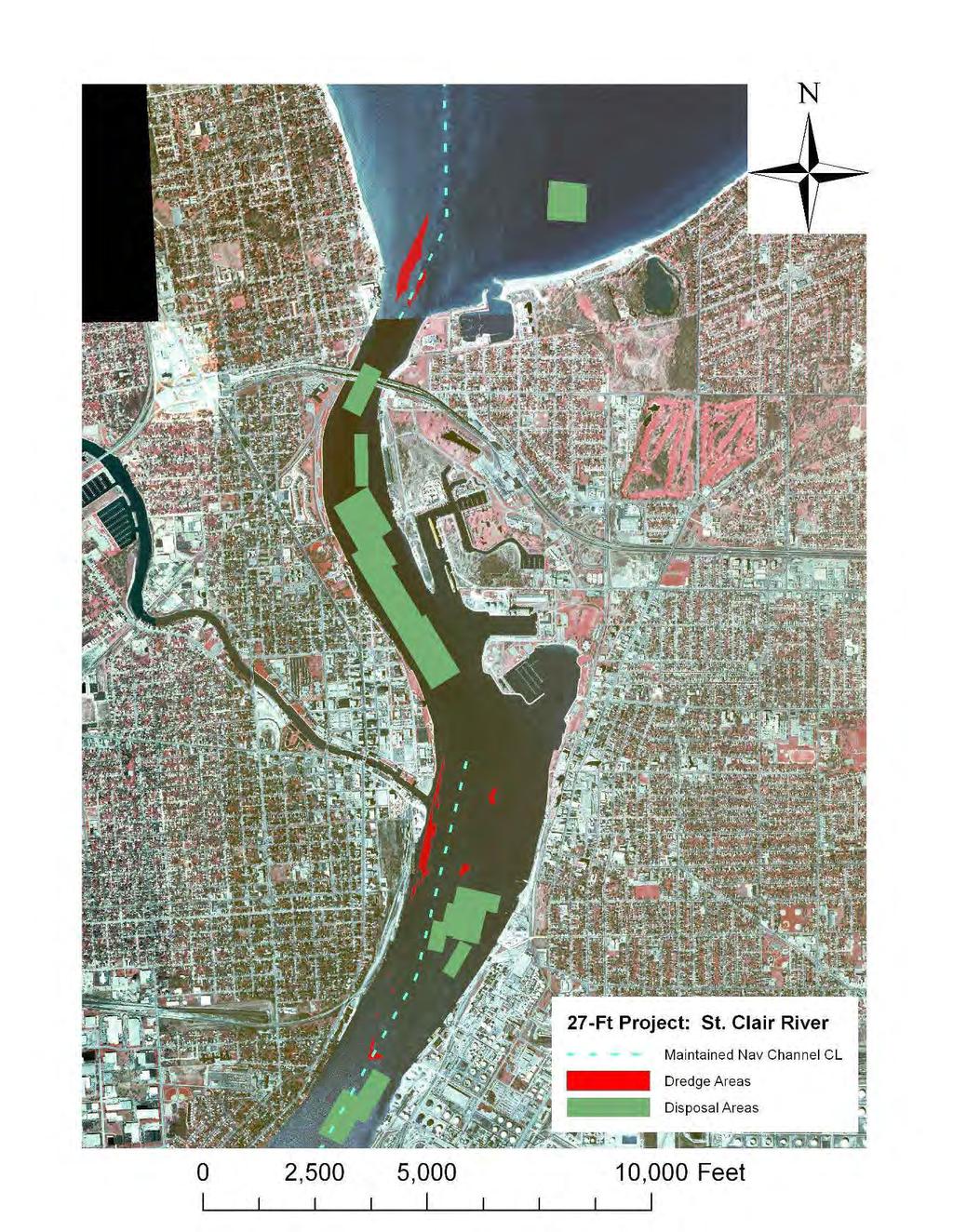
131 A- 2
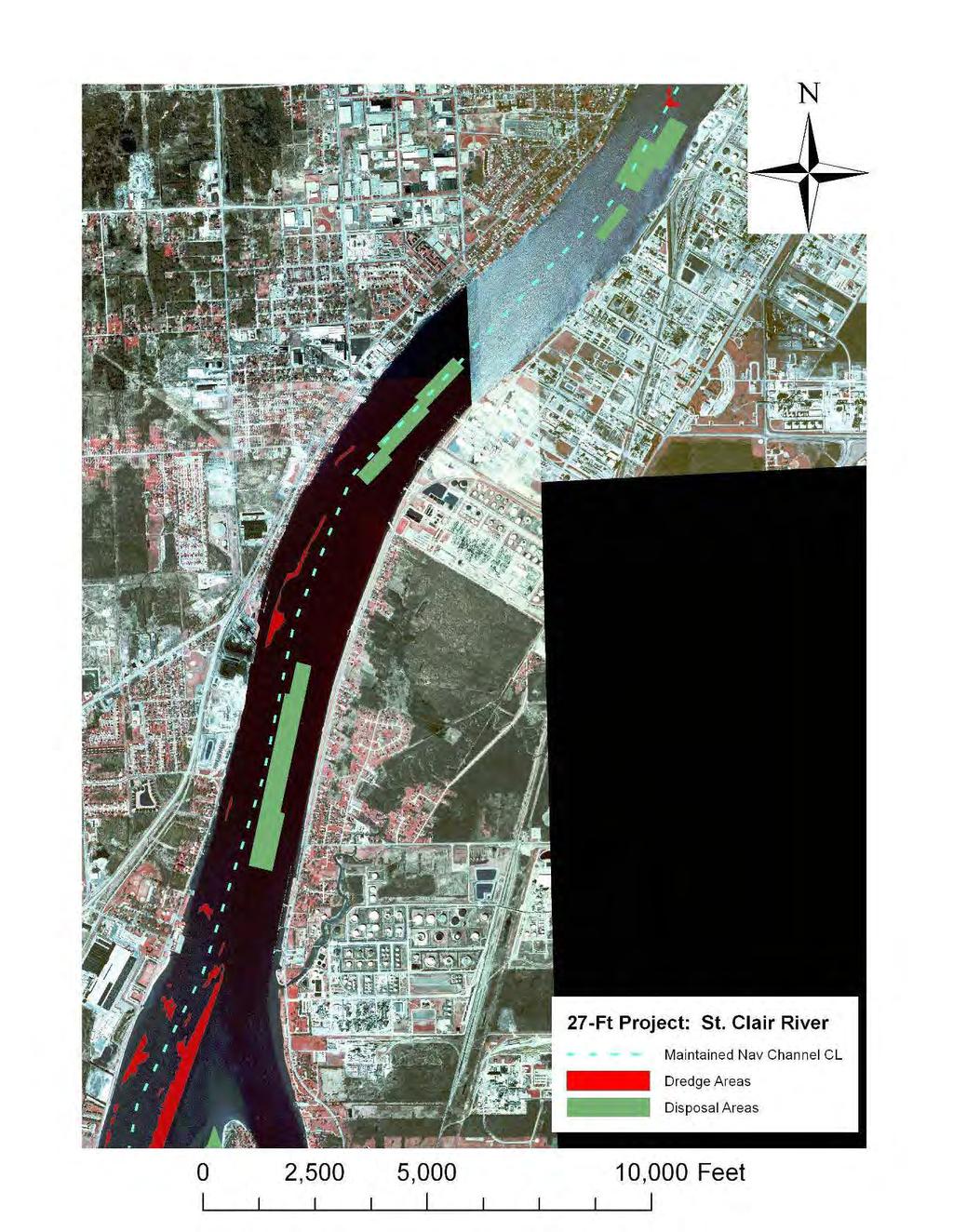
132 A- 3
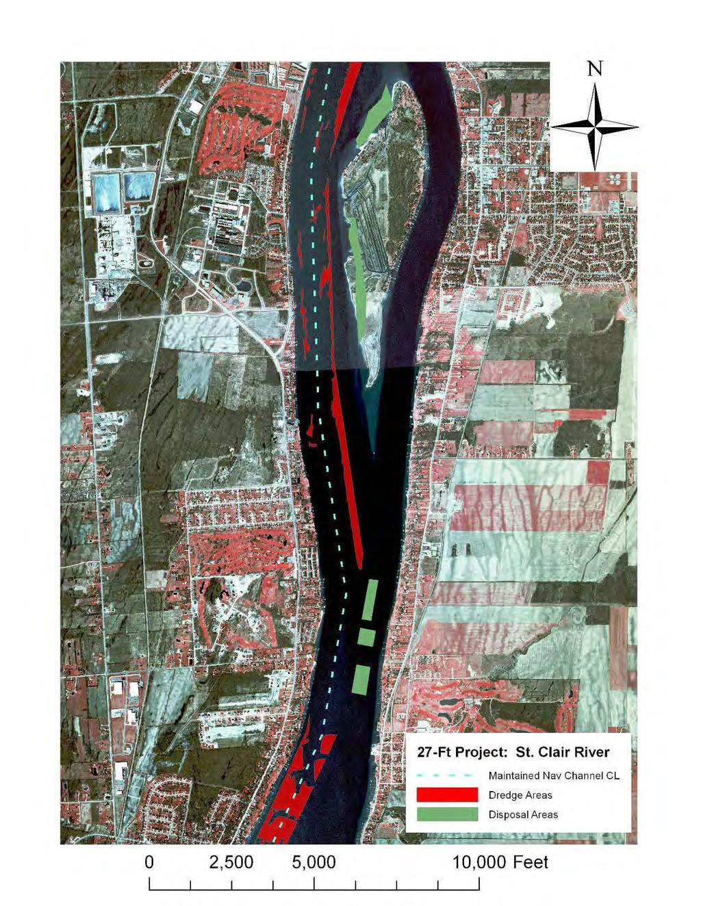
133 A- 4
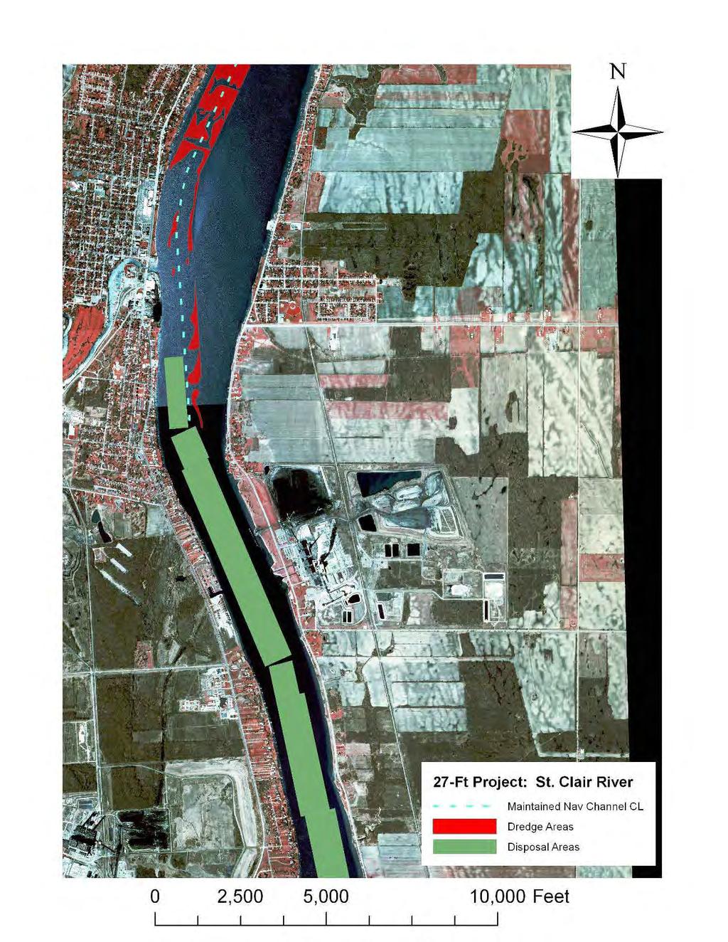
134 A- 5
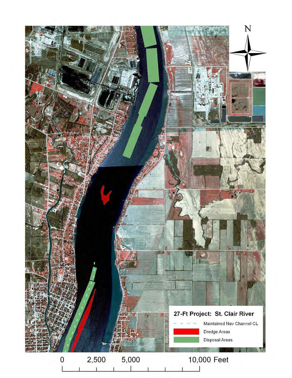
135 A- 6
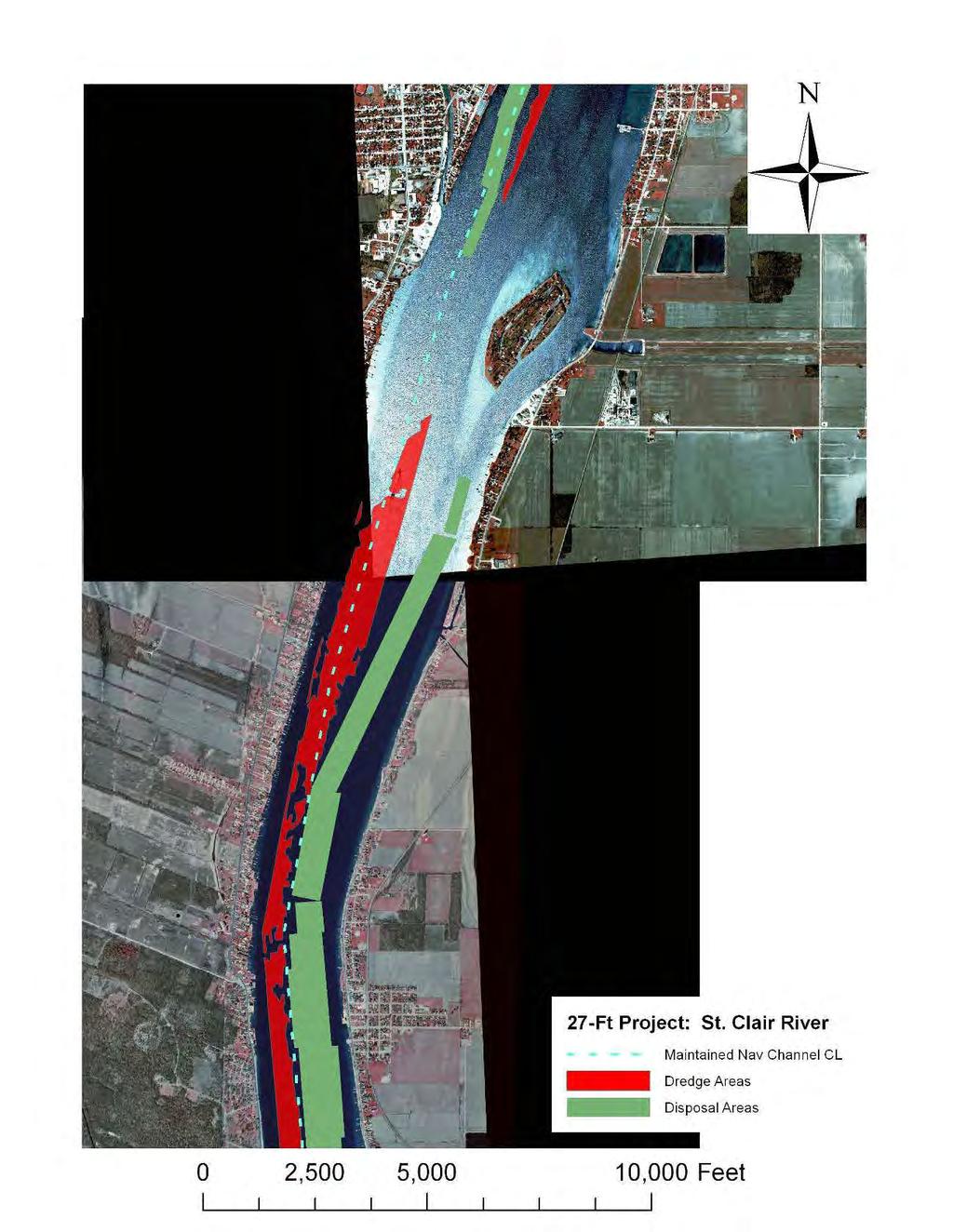
136 A- 7
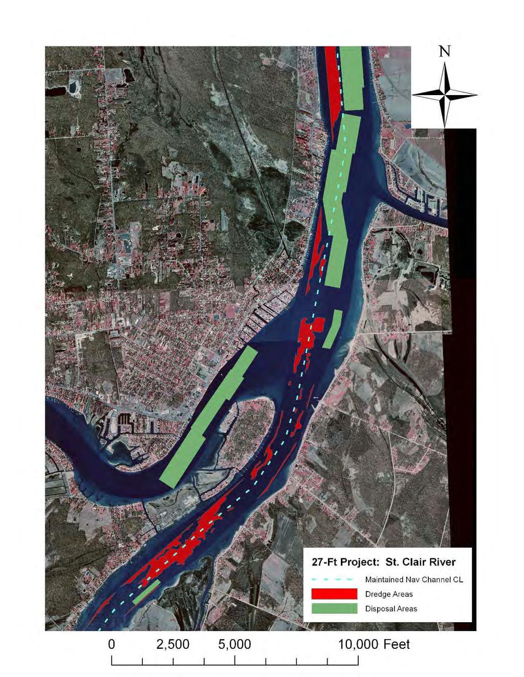
137 A- 8
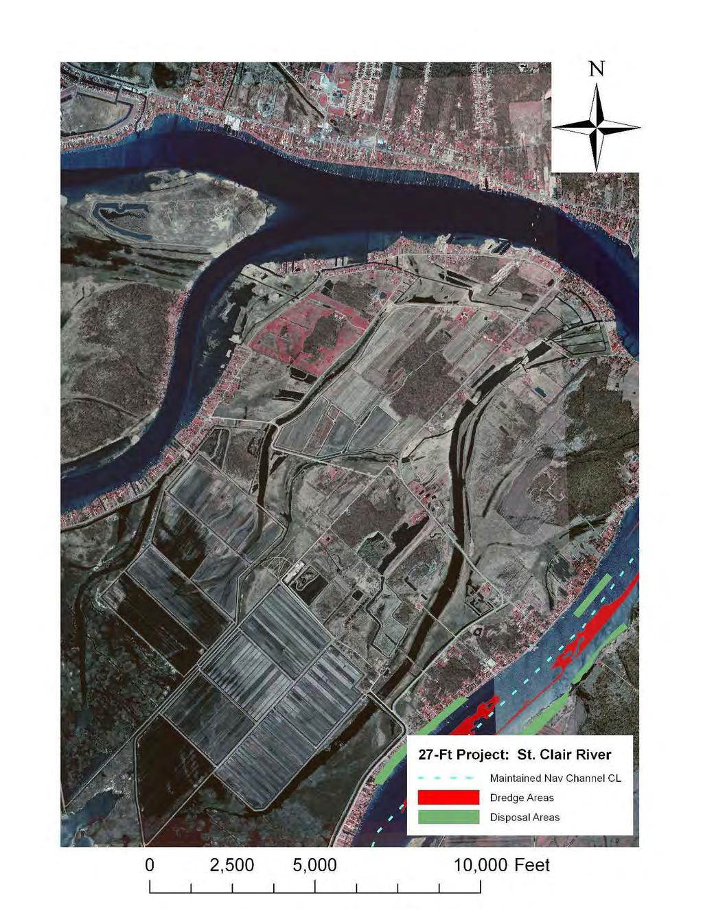
138 A- 9
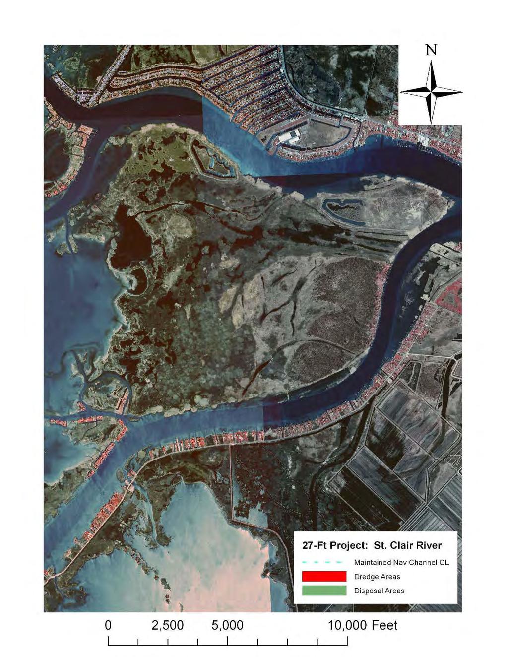
139 A- 10
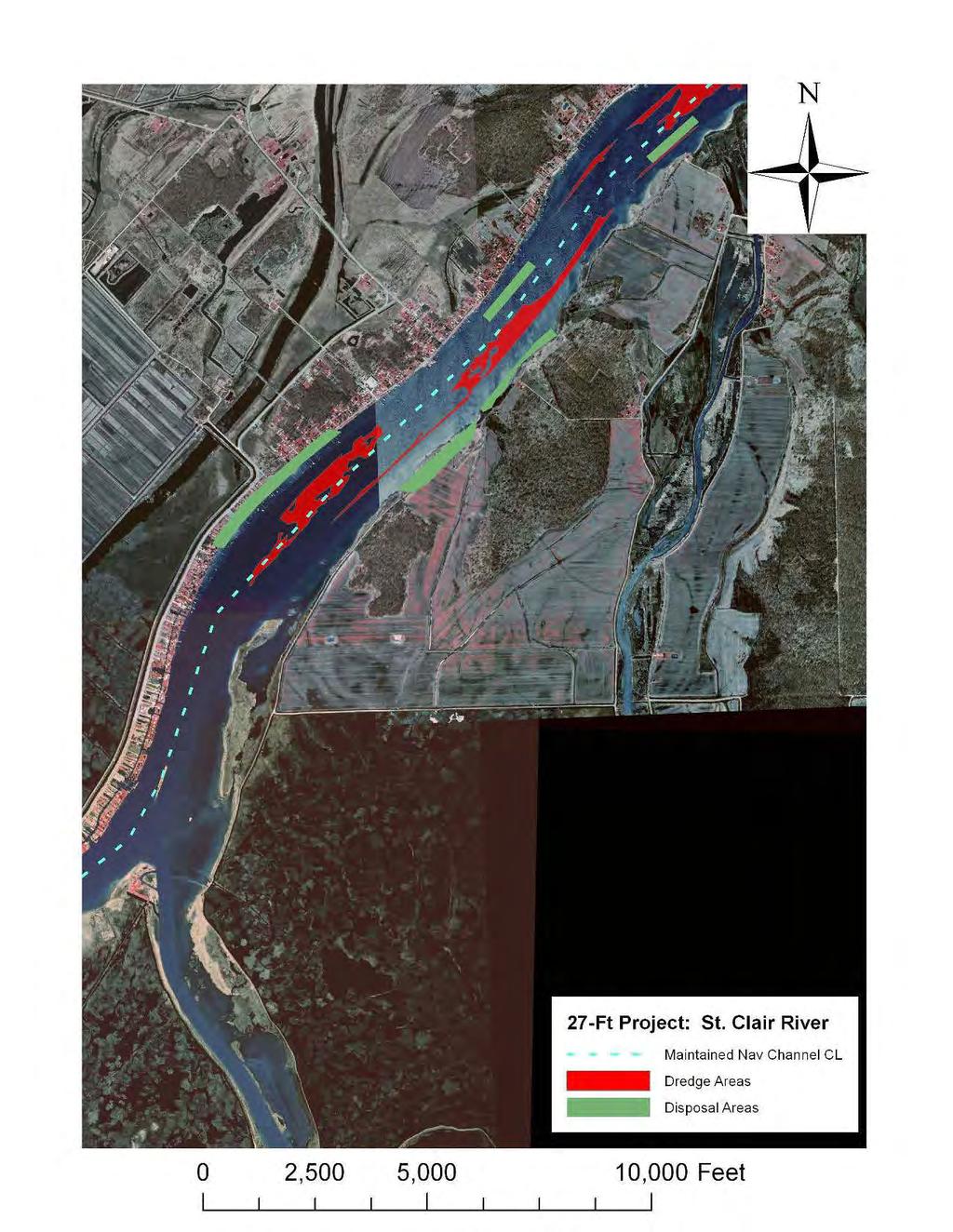
140 A- 11
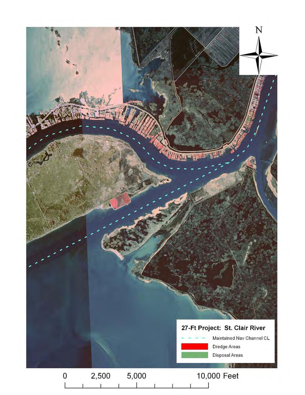
141 A- 12
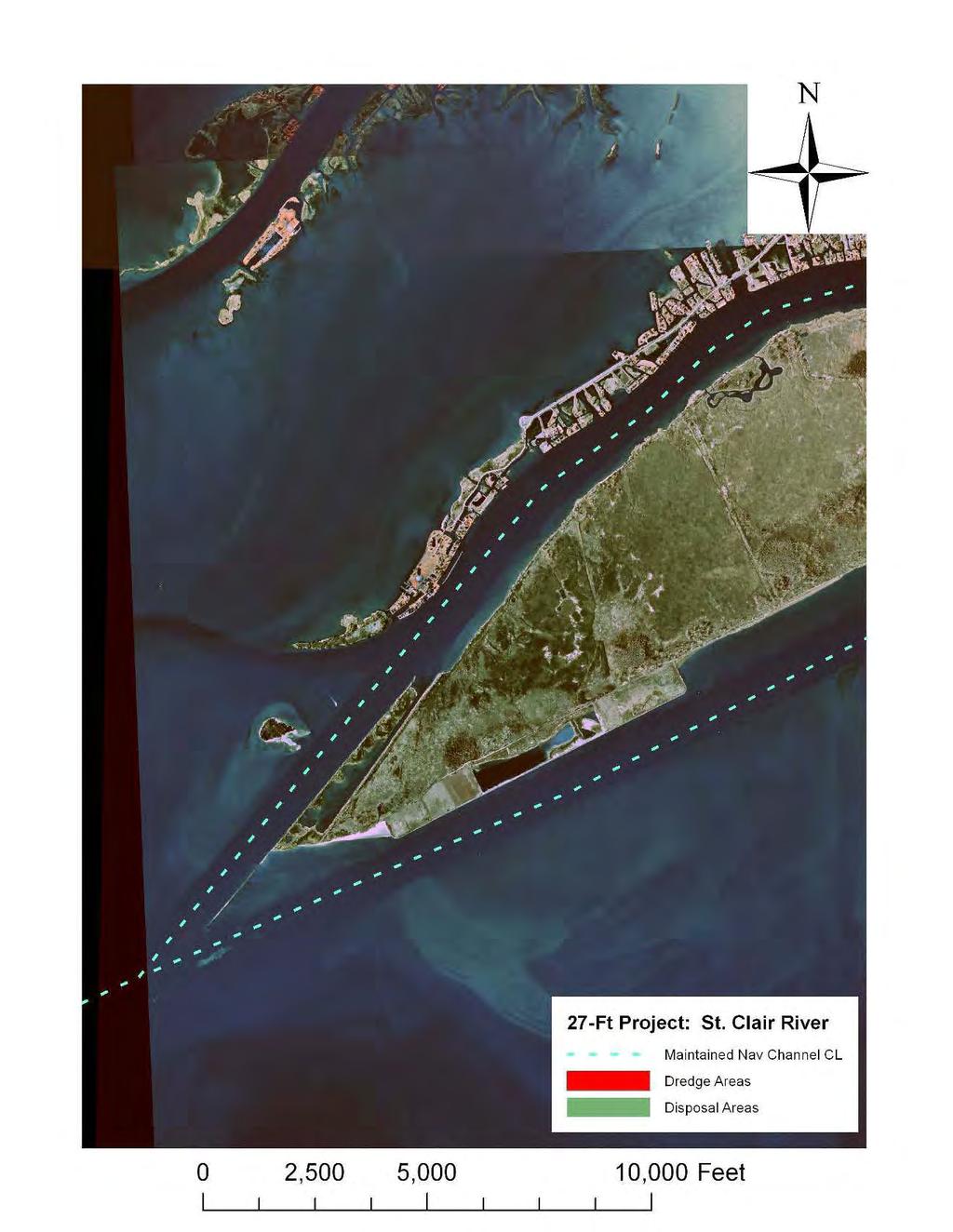
142 A- 13
143 APPENDIX B: Detroit River 27-Ft Project B- 1
144 B- 2
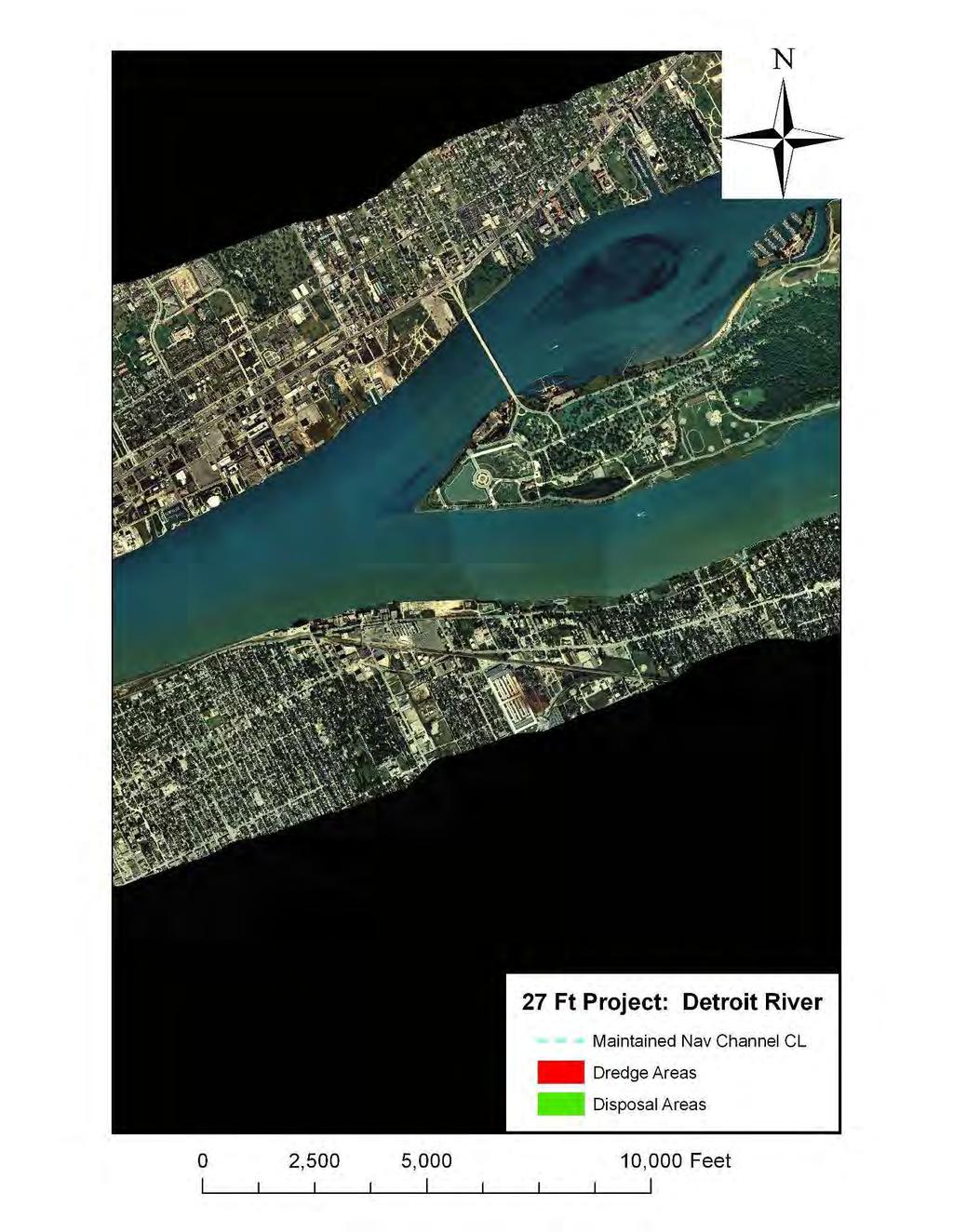
145 B- 3
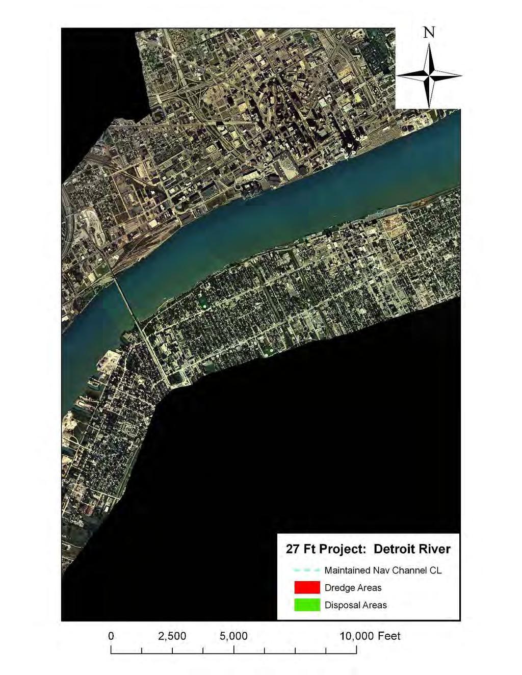
146 B- 4
147 B- 5
148 B- 6
149 B- 7
150 B- 8
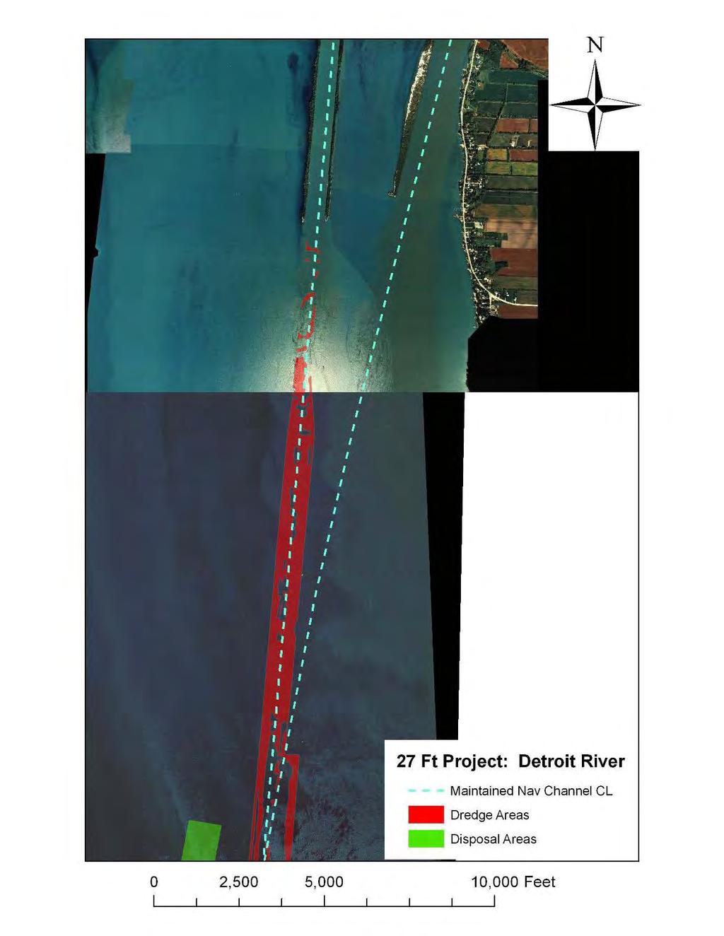
151 B- 9
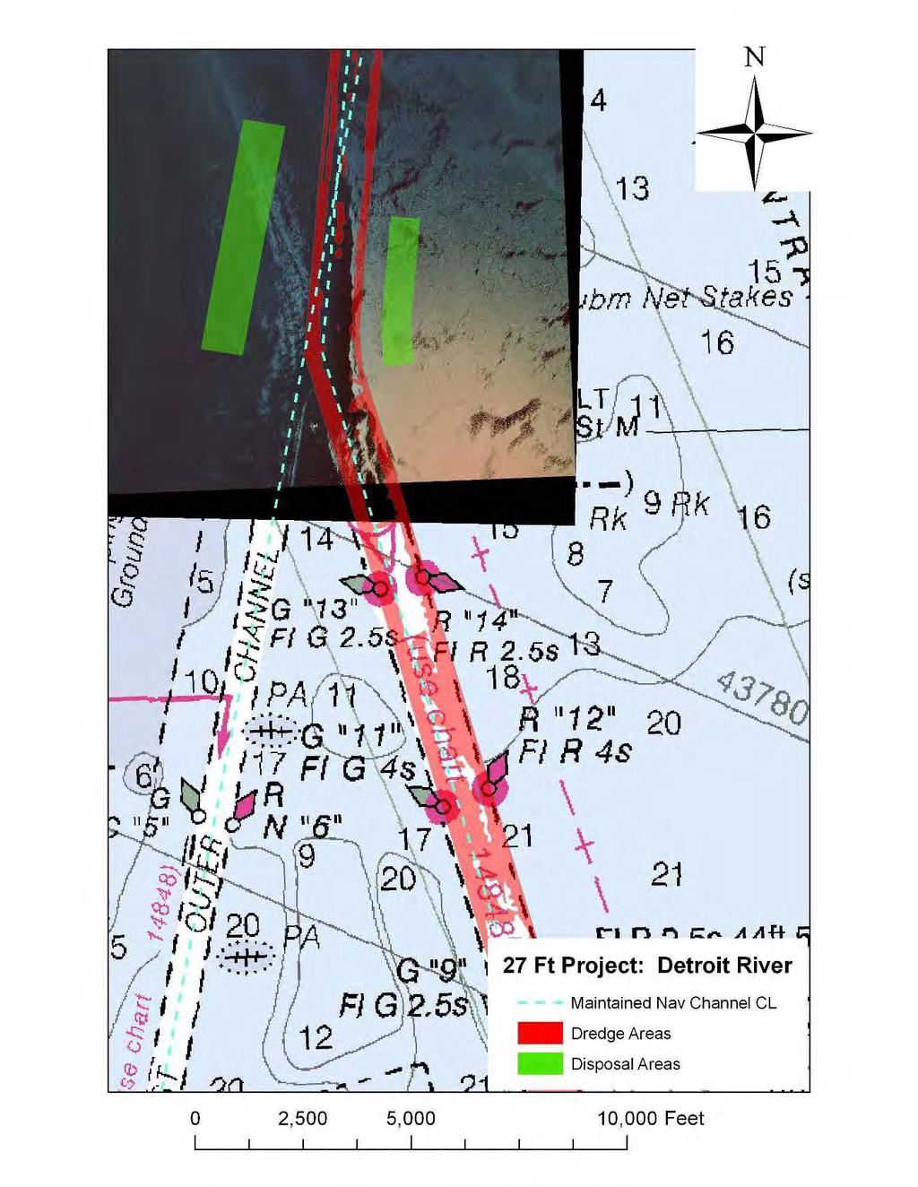
152 B- 10
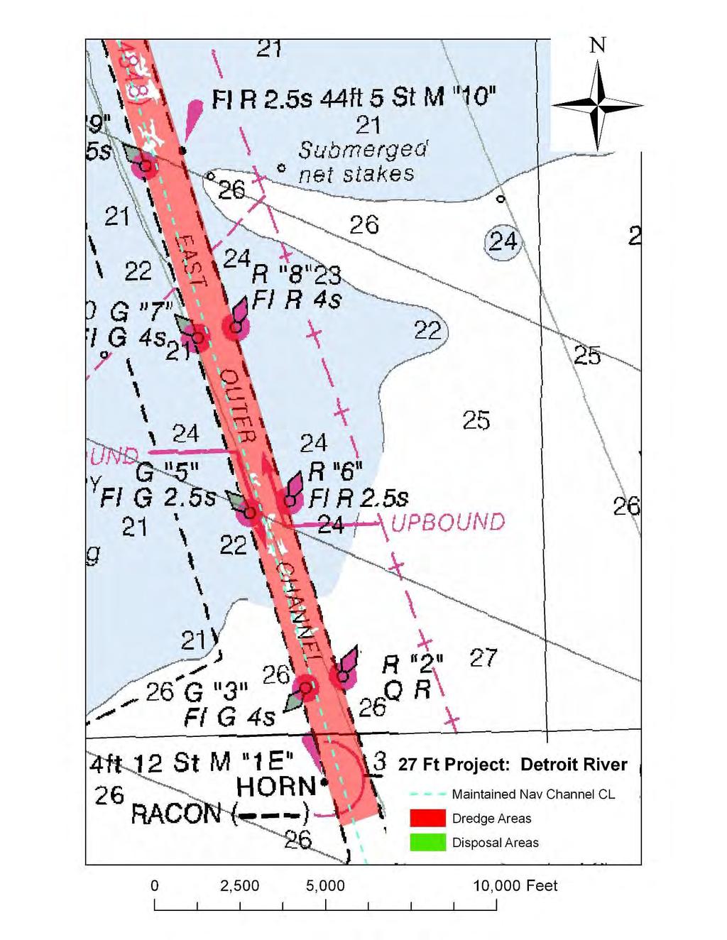
153 B- 11
CORPS FACTS. Harbor Dredging U.S. ARMY CORPS OF ENGINEERS BUILDING STRONG
 CORPS FACTS Harbor Dredging U.S. ARMY CORPS OF ENGINEERS BUILDING STRONG Disaster Response Sedimentation in the channel is caused by the normal cycle of silt movement, erosion from high water or heavy
1-32 NOME HARBOR, ALASKA (CWIS NOS , 87755, & 10422) Condition of Improvement 30 September 2009
 Condition of Improvement 30 September 2009") NOME HARBOR 1-32 NOME HARBOR, ALASKA (CWIS NOS. 72742, 87755, & 10422) Condition of Improvement 30 September 2009 AUTHORIZATION: (1) Rivers and Harbors Act, 8 August 1917 (House Doc. 1932, 64th Congress,
NOME HARBOR 1-32 NOME HARBOR, ALASKA (CWIS NOS. 72742, 87755, & 10422) Condition of Improvement 30 September 2009 AUTHORIZATION: (1) Rivers and Harbors Act, 8 August 1917 (House Doc. 1932, 64th Congress,
Juneau Douglas Harbor
 Juneau Douglas Harbor Douglas Harbor Page 2 of 8 Condition of Improvements 31 December 2015 Douglas Harbor, Alaska (CWIS No. 072789, 180942) Authorization Rivers and Harbors Act, 3 July 1958 (House Doc.
1-32 NOME HARBOR, ALASKA (CWIS NOS , 87755, 12270, & 10422) Condition of Improvement 30 September 2012
 Condition of Improvement 30 September 2012") NOME HARBOR 1-32 NOME HARBOR, ALASKA (CWIS NOS. 72742, 87755, 12270, & 10422) Condition of Improvement 30 September 2012 AUTHORIZATION: (1) Rivers and Harbors Act, 8 August 1917 (House Doc. 1932, 64th
NOME HARBOR 1-32 NOME HARBOR, ALASKA (CWIS NOS. 72742, 87755, 12270, & 10422) Condition of Improvement 30 September 2012 AUTHORIZATION: (1) Rivers and Harbors Act, 8 August 1917 (House Doc. 1932, 64th
DEPARTMENT OF THE ARMY GALVESTON DISTRICT, CORPS OF ENGINEERS P.O. BOX 1229 GALVESTON, TEXAS CESWG-CDR (1145)
") DEPARTMENT OF THE ARMY GALVESTON DISTRICT, CORPS OF ENGINEERS P.O. BOX 1229 GALVESTON, TEXAS 77553-1229 REPLY TO ATTENTION OF CESWG-CDR (1145) TBD MEMORANDUM FOR All Galveston District Personnel. SUBJECT:
DEPARTMENT OF THE ARMY GALVESTON DISTRICT, CORPS OF ENGINEERS P.O. BOX 1229 GALVESTON, TEXAS 77553-1229 REPLY TO ATTENTION OF CESWG-CDR (1145) TBD MEMORANDUM FOR All Galveston District Personnel. SUBJECT:
STRUCTURE S-65 PURPOSE SPILLWAY OPERATION
 STRUCTURE S-65 This structure is a reinforced concrete, gated spillway with discharge controlled by three cable operated, vertical lift gates, and a reinforced concrete lock structure with two pairs of
Nome Harbor Page 2 of 12
 Nome Harbor Nome Harbor Page 2 of 12 Condition of Improvements 30 December 2015 Nome Harbor, Alaska (CWIS No. 010422, 012270, 072742, 087755) Authorization (1) Rivers and Harbors Act, 8 August 1917 (House
DRAFT. October 17, 2014 File No Mr. Brendhan Zubricki Town Administrator Essex Town Hall 30 Martin Street Essex, MA.
 GZA GeoEnvironmental, Inc. Engineers and Scientists October 17, 2014 File No. 18.0171857.00 Mr. Brendhan Zubricki Town Administrator Essex Town Hall 30 Martin Street Essex, MA. 01929 DRAFT Re: Essex River
National Maritime Center
 National Maritime Center Providing Credentials to Mariners (Sample Examination) Page 1 of 8 Choose the best answer to the following Multiple Choice Questions. 1. Assume that your vessel has just entered
TOP:001.3 U.S. Fish and Wildlife Service TECHNICAL OPERATING PROCEDURE
 TOP:001.3 March 12, 2015 U.S. Fish and Wildlife Service Marquette Biological Station 3090 Wright Street Marquette, Michigan 49855 U.S.A. and U.S. Fish and Wildlife Service Ludington Biological Station
ST. LOUIS SECTION PROJECT OF THE YEAR AWARD
 ST. LOUIS SECTION PROJECT OF THE YEAR AWARD Originality and Innovation The St. Louis Harbor Project is located in the Upper Mississippi River between the entrance to the Chain of Rocks Canal at River
Annex E Bridge Pier Protection Plan
 Annex E Bridge Pier Protection Plan Table E1 Bridge Types and Locations Table E2 Flow Conditions For River Sections Figure E1 Bridge Abutment Protection Figure E2 Bridge Pier Protection Figure E3 Central
Ninilchik Harbor Page 2 of 11
 Ninilchik Harbor Ninilchik Harbor Page 2 of 11 Condition of Improvements 31 December 2017 Ninilchik Harbor, Alaska (CWIS No. 012640, 087345) Authorization Rivers and Harbors Act, 3 July 1958 (P.L. 85-500
ITEM 400 STRUCTURAL EXCAVATION AND BACKFILL
 AFTER MARCH 1, 2012 ITEM 400 STRUCTURAL EXCAVATION AND BACKFILL 400.1 Description. This item shall govern for all excavation required for the construction of all structures, except pipe or box sewers for
1-22. KETCHIKAN, ALASKA (Thomas and Bar Point Basins) (CWIS NOS & 87071) Condition of Improvement 30 September 2007
 (CWIS NOS & 87071) Condition of Improvement 30 September 2007") KETCHIKAN HARBOR 1-22 KETCHIKAN, ALASKA (Thomas and Bar Point Basins) (CWIS NOS. 00631 & 87071) Condition of Improvement 30 September 2007 AUTHORIZATION: (1) Rivers and Harbors Act, 3 July 1930 (House
KETCHIKAN HARBOR 1-22 KETCHIKAN, ALASKA (Thomas and Bar Point Basins) (CWIS NOS. 00631 & 87071) Condition of Improvement 30 September 2007 AUTHORIZATION: (1) Rivers and Harbors Act, 3 July 1930 (House
PROFILE OF SACRAMENTO RIVER, FREEPORT TO VERONA, CALIFORNIA,
 PROFILE OF SACRAMENTO RIVER, FREEPORT TO VERONA, CALIFORNIA, FLOOD OF FEBRUARY 1986 By J.C. Blodgett and J.B. Lucas U.S. GEOLOGICAL SURVEY Open-File Report 88-82 CO CM I m r-h CM Sacramento, California
APPENDIX B HYDRAULIC DESIGN DATA FOR CULVERTS
 TM 5-820-4/AFM 88-5, Chap 4 APPENDIX B HYDRAULIC DESIGN DATA FOR CULVERTS B-1. General. a. This appendix presents diagrams, charts, coefficients and related information useful in design of culverts. The
JAP Additional Information Sheet
 JAP Additional Information Sheet Block 15: Purpose and Need The USACE purpose of the project is to provide a safe and reliable whitewater park for the recreational public in a city park, which will provide
ROOK COMPANY PANAMA CANAL BANCROFT LIBRARY
 F 1563 ROOK COMPANY PANAMA CANAL BANCROFT LIBRARY University of California Berkeley TTTe PANAMA CANAL I The Land Divided Fin The World Unvted ' A Pidtorial Review of its Construction together with
Hydrographic Surveying Methods, Applications and Uses
 Definition: Hydrographic Surveying Methods, Applications and Uses It is the branch of surveying which deals with any body of still or running water such as a lake, harbor, stream or river. Hydrographic
MOREHEAD CITY HARBOR, NC. Dredged Material Management Plan (DMMP)
") MOREHEAD CITY HARBOR, NC Dredged Material Management Plan (DMMP) Public Meeting/Info Session 15 January 2014 US Army Corps of Engineers Morehead City Harbor DMMP Presentation Topics Morehead City Harbor
MOREHEAD CITY HARBOR, NC Dredged Material Management Plan (DMMP) Public Meeting/Info Session 15 January 2014 US Army Corps of Engineers Morehead City Harbor DMMP Presentation Topics Morehead City Harbor
Technical Brief - Wave Uprush Analysis Island Harbour Club, Gananoque, Ontario
 Technical Brief - Wave Uprush Analysis RIGGS ENGINEERING LTD. 1240 Commissioners Road West Suite 205 London, Ontario N6K 1C7 October 31, 2014 Table of Contents Section Page Table of Contents... i List
HARBOR INFRASTRUCTURE INVENTORIES Port Sanilac Harbor, Michigan
 HARBOR INFRASTRUCTURE INVENTORIES Port Sanilac Harbor, Michigan Harbor Location: Port Sanilac Harbor is located on the west shore of Lake Huron, about 30 miles north of Port Huron, MI. Authority: Rivers
Advanced Hydraulics Prof. Dr. Suresh A. Kartha Department of Civil Engineering Indian Institute of Technology, Guwahati
 Advanced Hydraulics Prof. Dr. Suresh A. Kartha Department of Civil Engineering Indian Institute of Technology, Guwahati Module - 4 Hydraulic Jumps Lecture - 1 Rapidly Varied Flow- Introduction Welcome
Ketchikan Harbors Thomas Basin and Bar Point Harbor
 Ketchikan Harbors Thomas Basin and Bar Point Harbor Condition of Improvements 30 December 2014 Thomas Basin & Bar Point Harbors Ketchikan, Alaska (CWIS No. 000631 & 087071) Authorization (1) Rivers and
Discussion on the Selection of the Recommended Fish Passage Design Discharge
 Discussion on the Selection of the Recommended Fish Passage Design Discharge Introduction The provision of fish passage is a requirement for most proposed culvert and bridge installations in Alberta, depending
CLAIBORNE LOCK AND DAM PERTINENT DATA
 CLAIBORNE LOCK AND DAM PERTINENT DATA GENERAL Location Clarke, Monroe, & Wilcox Counties, Alabama; Alabama River, river mile 72.5 Drainage area Millers Ferry to Claiborne sq. mi. 836 Total drainage area
Figure 4, Photo mosaic taken on February 14 about an hour before sunset near low tide.
 The Impact on Great South Bay of the Breach at Old Inlet Charles N. Flagg and Roger Flood School of Marine and Atmospheric Sciences, Stony Brook University Since the last report was issued on January 31
Implications of proposed Whanganui Port and lower Whanganui River dredging
 PO Box 637 Wanganui 4540 Attention: Rowan McGregor Dear Rowan 1 Summary We understand that it has been proposed to bring large vessels into the Port at Whanganui requiring the excavation of a channel up
HARBOUR SEDIMENTATION - COMPARISON WITH MODEL
 HARBOUR SEDIMENTATION - COMPARISON WITH MODEL ABSTRACT A mobile-bed model study of Pointe Sapin Harbour, in the Gulf of St. Lawrence, resulted in construction of a detached breakwater and sand trap to
APPENDIX C VEGETATED EMERGENCY SPILLWAY. VERSION 1.0 March 1, 2011
 APPENDIX C VEGETATED EMERGENCY SPILLWAY VERSION 1.0 March 1, 2011 [NOTE: Could use a better photo more clearly showing the emergency spillway in the context of the dam.] SECTION C-1: DESCRIPTION OF PRACTICE
Condition of Improvements 30 December 2014 Wrangell Harbors, Alaska (CWIS No , )
") Wrangell Harbors Condition of Improvements 30 December 2014 Wrangell Harbors, Alaska (CWIS No. 010435, 021500) Authorization (1) Rivers and Harbors Act, 22 September 1922 (House Doc. 161, 67th Congress,
Wrangell Harbors Condition of Improvements 30 December 2014 Wrangell Harbors, Alaska (CWIS No. 010435, 021500) Authorization (1) Rivers and Harbors Act, 22 September 1922 (House Doc. 161, 67th Congress,
LAB: WHERE S THE BEACH
 Name: LAB: WHERE S THE BEACH Introduction When you build a sandcastle on the beach, you don't expect it to last forever. You spread out your towel to sunbathe, but you know you can't stay in the same spot
Feasibility Study for Restoration of Titlow Lagoon Fish Passage. South Puget Sound Salmon Enhancement Group
 Feasibility Study for Restoration of Titlow Lagoon Fish Passage South Puget Sound Salmon Enhancement Group January 2010 Feasibility Study for Restoration of Titlow Lagoon Fish Passage Prepared for South
Plan B Dam Breach Assessment
 Plan B Dam Breach Assessment Introduction In support of the Local Sponsor permit applications to the states of Minnesota and North Dakota, a dam breach analysis for the Plan B alignment of the Fargo-Moorhead
Julebæk Strand. Effect full beach nourishment
 Julebæk Strand Effect full beach nourishment Aim of Study This study is a part of the COADAPT funding and the aim of the study is to analyze the effect of beach nourishment. In order to investigate the
STRUCTURE 65-B PURPOSE SPILLWAY OPERATION
 STRUCTURE 65-B This structure is a reinforced concrete, gated spillway with discharge controlled by three cable operated vertical lift gates and a reinforced concrete lock structure with two pairs of sector
Great Lakes Commission Semiannual Meeting
 Great Lakes Commission Semiannual Meeting Great Lakes Water Levels Forecasts March 6, 2013 Washington D.C. Keith Kompoltowicz Chief, Watershed Hydrology Detroit District Corps of Engineers Recent Analysis/Forecast
APPENDIX C. Fluvial and Tidal Hydraulics Report
 APPENDIX C Fluvial and Tidal Hydraulics Report BUENA VISTA LAGOON ENHANCEMENT PROJECT FLUVIAL AND TIDAL HYDRAULICS ANALYSES Prepared for: SANDAG 401 B Street, Suite 800 San Diego, California 92101 Contact:
TECHNICAL MEMORANDUM 002 EMORANNO. 001
 TECHNICAL MEMORANDUM 002 EMORANNO. 001 To: Jack Synder, P.E. EES Consulting From: Mort McMillen, P.E. Paul Larson, SE Date: October 13, 2010 Project: Cc: Taylor Bowen Subject: Technical Memorandum (TM)
OFFICE OF STRUCTURES MANUAL FOR HYDROLOGIC AND HYDRAULIC DESIGN CHAPTER 11 APPENDIX B TIDEROUT 2 USERS MANUAL
 OFFICE OF STRUCTURES MANUAL FOR HYDROLOGIC AND HYDRAULIC DESIGN CHAPTER 11 APPENDIX B TIDEROUT 2 USERS MANUAL APRIL 2011 APRIL 2011 Page 1 Preface TIDEROUT 2, Build 1.22 dated June 29, 2006 is the current
SUBMERGED VENTURI FLUME. Tom Gill 1 Robert Einhellig 2 ABSTRACT
 SUBMERGED VENTURI FLUME Tom Gill 1 Robert Einhellig 2 ABSTRACT Improvement in canal operating efficiency begins with establishing the ability to measure flow at key points in the delivery system. The lack
3. GRADUALLY-VARIED FLOW (GVF) AUTUMN 2018
 AUTUMN 2018") 3. GRADUALLY-VARIED FLOW (GVF) AUTUMN 2018 3.1 Normal Flow vs Gradually-Varied Flow V 2 /2g EGL (energy grade line) Friction slope S f h Geometric slope S 0 In flow the downslope component of weight balances
3. GRADUALLY-VARIED FLOW (GVF) AUTUMN 2018 3.1 Normal Flow vs Gradually-Varied Flow V 2 /2g EGL (energy grade line) Friction slope S f h Geometric slope S 0 In flow the downslope component of weight balances
APPENDIX J HYDROLOGY AND WATER QUALITY
 APPENDIX J HYDROLOGY AND WATER QUALITY J-1 Technical Report on Airport Drainage, Northern Sector Airport and Ordinance Creek Watershed / Preliminary Creek Constructed Natural Channel Culvert J-2 Preliminary
Friends of the Detroit River Habitat Restoration Project Update
 Friends of the Detroit River Habitat Restoration Project Update 11 Beneficial Use Impairments (BUIs) were originally identified to be associated with the Detroit River: 1. Restrictions on fish and wildlife
RE: Hurricane Matthew Beach Damage Assessment and Recommendations [CSE 2416]
![RE: Hurricane Matthew Beach Damage Assessment and Recommendations [CSE 2416]](/thumbs/83/87675702.jpg "RE: Hurricane Matthew Beach Damage Assessment and Recommendations [CSE 2416]") October 25, 2016 Iris Hill Town Administrator Town of Edisto Beach 2414 Murray St Edisto Beach SC 29438 RE: Hurricane Matthew Beach Damage Assessment and Recommendations [CSE 2416] Dear Iris, Hurricane
October 25, 2016 Iris Hill Town Administrator Town of Edisto Beach 2414 Murray St Edisto Beach SC 29438 RE: Hurricane Matthew Beach Damage Assessment and Recommendations [CSE 2416] Dear Iris, Hurricane
SEDIMENTATION AND NAVIGATION STUDY OF THE LOWER MISSISSIPPI RIVER AT THE WHITE RIVER CONFLUENCE, MILES 603 TO 596 HYDRAULIC MICRO MODEL INVESTIGATION
 Technical Report M7 SEDIMENTATION AND NAVIGATION STUDY OF THE LOWER MISSISSIPPI RIVER AT THE WHITE RIVER CONFLUENCE, MILES 603 TO 596 HYDRAULIC MICRO MODEL INVESTIGATION By David C. Gordon Robert D. Davinroy
Information for File # SEW
 Information for File #2014-02744-SEW Applicant: Minnesota Department of Transportation (MnDOT), District 3; c/o Mr. Robert Nibbe Corps Contact: Sarah Wingert, U.S. Army Corps of Engineers, 180 5 th Street
CHAPTER 134 INTRODUCTION
 CHAPTER 134 NEW JETTIES FOR TUNG-KANG FISHING HARBOR, TAIWAN Chi-Fu Su Manager Engineering Department Taiwan Fisheries Consultants, Inc. Taipei, Taiwan INTRODUCTION Tung-Kang Fishing Harbor, which is about
1-44. SITKA HARBOR, ALASKA (Western Channel, Crescent Bay Basin, Channel Rock Breakwaters) (CWIS NOS , 16840, 10322, 55030, 13787)
 (CWIS NOS , 16840, 10322, 55030, 13787)") SITKA 1-44 SITKA HARBOR, ALASKA (Western Channel, Crescent Bay Basin, Channel Rock Breakwaters) (CWIS NOS. 72845, 16840, 10322, 55030, 13787) Condition of Improvement 30 September 2011 AUTHORIZATION:
SITKA 1-44 SITKA HARBOR, ALASKA (Western Channel, Crescent Bay Basin, Channel Rock Breakwaters) (CWIS NOS. 72845, 16840, 10322, 55030, 13787) Condition of Improvement 30 September 2011 AUTHORIZATION:
V. HARBOR DEPTHS, CHANNEL DESIGN AND PROPOSED CONSTRUCTION AND DREDGING
 V. HARBOR DEPTHS, CHANNEL DESIGN AND PROPOSED CONSTRUCTION AND DREDGING A. DISCUSSION: For the most part, projects that involve dredging and construction require a comprehensive design and review process
Water Resources Report RKLD Annual Meeting July 30, 2016
 Water Resources Report RKLD Annual Meeting 2016 July 30, 2016 Topics Hydrology Report Indianford Dam trash rack cleanout performance Experimental Project update Review of PAS project Twin floods- 1 to
EXAMPLES (OPEN-CHANNEL FLOW) AUTUMN 2018
 AUTUMN 2018") EXAMPLES (OPEN-CHANNEL FLOW) AUTUMN 2018 Normal and Critical Depths Q1. If the discharge in a channel of width 5 m is 20 m 3 s 1 and Manning s n is 0.02 m 1/3 s, find: (a) the normal depth and Froude number
EXAMPLES (OPEN-CHANNEL FLOW) AUTUMN 2018 Normal and Critical Depths Q1. If the discharge in a channel of width 5 m is 20 m 3 s 1 and Manning s n is 0.02 m 1/3 s, find: (a) the normal depth and Froude number
An Update of Coastal Erosion in Puerto Rico
 Jack Morelock and Maritza Barreto An Update of Coastal Erosion in Puerto Rico Department of Marine Sciences, University of Puerto Rico at Mayagüez and Geography Department, University of Puerto Rico at
Introducing the Great Lakes
 Introducing the Great Lakes Just a few years ago, geologically speaking, a glacier passed this way, and that's why the Midwest has the Great Lakes. Size The Great Lakes and their connecting channels form
Comparison of Predicted and Measured Shoaling at Morro Bay Harbor Entrance, California
 Comparison of Predicted and Measured Shoaling at Morro Bay Harbor Entrance, California by Edward F. Thompson, Inocencio P. DiRamos, and Robert R. Bottin, Jr. PURPOSE: This Coastal and Hydraulics Engineering
CHAPTER 6 10/29/2018 Clean Version REGULATING PIERS, WHARVES, MOORING BUOYS, SWIMMING RAFTS AND INFLATABLES ON ROCK LAKE
 1 2 3 4 5 6 7 8 9 10 11 12 13 14 15 16 17 18 19 20 21 22 23 24 25 26 27 28 29 30 31 32 33 34 35 36 37 38 39 40 41 42 43 44 45 46 CHAPTER 6 10/29/2018 Clean Version REGULATING PIERS, WHARVES, MOORING BUOYS,
(Revised February,2005) CULVERTS, BRIDGES, AND FORDS
 CULVERTS, BRIDGES, AND FORDS") GUIDE TO STREAM CROSSINGS (Revised February,2005) CULVERTS, BRIDGES, AND FORDS Culverts, bridges, and fords are all methods used to cross-streams. Culverts are the most common stream crossing structure.
GUIDE TO STREAM CROSSINGS (Revised February,2005) CULVERTS, BRIDGES, AND FORDS Culverts, bridges, and fords are all methods used to cross-streams. Culverts are the most common stream crossing structure.
Rock Ramp Design Guidelines. David Mooney MS Chris Holmquist-Johnson MS Drew Baird Ph.D. P.E. Kent Collins P.E.
 Rock Ramp Design Guidelines David Mooney MS Chris Holmquist-Johnson MS Drew Baird Ph.D. P.E. Kent Collins P.E. Rock Ramp Design Guidelines OUTLINE Local and System Interactions with Rock Ramps Ramp Geometry
Dredging Keeping Our Underwater Highways Open
 Dredging Keeping Our Underwater Highways Open Sedimentation Material that falls to the bottom of a liquid is called sediment. If enough sediment deposits to build a shallow spot on the river or ocean bottom,
BENEFIT-COST ANALYSIS OF HARBOR DREDGING ON THE GREAT LAKES
 Middle States Geographer, 997,30:55-6 BENEFT-COST ANALYSS OF HARBOR DREDGNG ON THE GREAT LAKES Raymond W. Waxmonsk:y Department of Geography & Planning Buffalo State College Buffalo, NY 4222 ABSTRACT:
Environmental. Effects of Dredging
 Envi~onmental Effects of Dredging Technical Notes THE VALUE OF GRAVEL DISPOSAL MOUNDS IN RIVER SIDE CHANNELS FOR FRESHWATER MUSSELS PURPOSE: This note provides information on the value of gravel disposal
UNDERWATER BRIDGE INSPECTION REPORT DISTRICT 1 PINE COUNTY
 UNDERWATER BRIDGE INSPECTION REPORT STRUCTURE NO. 58551 CSAH NO. 41 OVER THE KETTLE RIVER DISTRICT 1 PINE COUNTY JULY 28, 2012 PREPARED FOR THE MINNESOTA DEPARTMENT OF TRANSPORTATION BY COLLINS ENGINEERS,
The Impact on Great South Bay of the Breach at Old Inlet Charles N. Flagg School of Marine and Atmospheric Sciences, Stony Brook University
 The Impact on Great South Bay of the Breach at Old Inlet Charles N. Flagg School of Marine and Atmospheric Sciences, Stony Brook University The previous report provided a detailed look at the conditions
CLAM PASS RESTORATION AND MANAGEMENT PLAN BATHYMETRIC MONITORING REPORT NO. 7 Including Interior Bay Dredge Cuts and Tidal Data
 CLAM PASS RESTORATION AND MANAGEMENT PLAN BATHYMETRIC MONITORING REPORT NO. 7 Including Interior Bay Dredge Cuts and Tidal Data Submitted to: Florida Department of Environmental Protection DEP File No.
SACO RIVER AND CAMP ELLIS BEACH SACO, MAINE SECTION 111 SHORE DAMAGE MITIGATION PROJECT APPENDIX F ECONOMIC ASSESSMENT
 SACO RIVER AND CAMP ELLIS BEACH SACO, MAINE SECTION 111 SHORE DAMAGE MITIGATION PROJECT APPENDIX F ECONOMIC ASSESSMENT Department of the Army New England District, Corps of Engineers 696 Virginia Road
ALTERNATIVES FOR COASTAL STORM DAMAGE MITIGATION AND FUNCTIONAL DESIGN OF COASTAL STRUCTURES
 The University of the West Indies Organization of American States PROFESSIONAL DEVELOPMENT PROGRAMME: COASTAL INFRASTRUCTURE DESIGN, CONSTRUCTION AND MAINTENANCE A COURSE IN COASTAL DEFENSE SYSTEMS I CHAPTER
UNDERWATER BRIDGE INSPECTION REPORT STRUCTURE NO CSAH NO. 7 OVER THE SNAKE RIVER DISTRICT 1 - PINE COUNTY
 UNDERWATER BRIDGE INSPECTION REPORT STRUCTURE NO. 58506 CSAH NO. 7 OVER THE SNAKE RIVER DISTRICT 1 - PINE COUNTY PREPARED FOR THE MINNESOTA DEPARTMENT OF TRANSPORTATION BY COLLINS ENGINEERS, INC. JOB NO.
ALTERNATIVES FOR COASTAL STORM DAMAGE MITIGATION
 ALTERNATIVES FOR COASTAL STORM DAMAGE MITIGATION Dave Basco Old Dominion University, Norfolk, Virginia, USA National Park Service Photo STRUCTURAL (changes to natural, physical system) hardening (seawalls,
APPENDIX M DREDGED MATERIAL MANAGEMENT PLAN (DMMP) FINAL INTEGRATED FEASIBILITY REPORT AND ENVIRONMENTAL ASSESSMENT
 FINAL INTEGRATED FEASIBILITY REPORT AND ENVIRONMENTAL ASSESSMENT") APPENDIX M DREDGED MATERIAL MANAGEMENT PLAN (DMMP) Brazos Island Harbor, Texas Channel Improvement Study FINAL INTEGRATED FEASIBILITY REPORT AND ENVIRONMENTAL ASSESSMENT This page is intentionally left
APPENDIX M DREDGED MATERIAL MANAGEMENT PLAN (DMMP) Brazos Island Harbor, Texas Channel Improvement Study FINAL INTEGRATED FEASIBILITY REPORT AND ENVIRONMENTAL ASSESSMENT This page is intentionally left
Lecture 1 Why Do We Have Levees in Louisiana? J. David Rogers, Ph.D., P.E., R.G.
 Lecture 1 Why Do We Have Levees in Louisiana? J. David Rogers, Ph.D., P.E., R.G. Karl F. Hasselmann Chair in Geological Engineering Missouri University of Science & Technology for the First Annual Levee
CLAM PASS ANNUAL RESTORATION & MANAGEMENT PLAN TIDAL ANALYSIS ELEMENT REPORT NO. 13
 CLAM PASS ANNUAL RESTORATION & MANAGEMENT PLAN TIDAL ANALYSIS ELEMENT REPORT NO. 13 Submitted to: Pelican Bay Services Division Prepared by: Humiston & Moore Engineers H&M File No. 13-078 November 2012
The St. Lawrence Seaway--To Mid-Continent by Ocean Vessel
 Case Western Reserve Law Review Volume 11 Issue 1 1959 The St. Lawrence Seaway--To Mid-Continent by Ocean Vessel Lewis W. Britton Follow this and additional works at: http://scholarlycommons.law.case.edu/caselrev
INTERNATIONAL HYDROGRAPHIC SURVEY STANDARDS
 INTERNATIONAL HYDROGRAPHIC SURVEY STANDARDS by Gerald B. MILLS 1 I. Background The International Hydrographic Organization (IHO) traces its origin to the establishment of the International Hydrographic
Illinois State Water Survey
 Illinois State Water Survey HYDROLOGY DIVISION SWS Contract Report 508 COMPARISON OF 1987 AND 1989 BED PROFILE SURVEYS OF THE LOWER CACHE RIVER by Richard Allgire Office of Sediment and Wetland Studies
Eelgrass and Macroalgae Presence/Absence Preliminary Surveys BHP Proposed Grays Harbor Potash Export Facility A Task 400
 Memorandum 40600-HS-MEM-55036 Revision 0 Date: 26 July 2018 Subject: Eelgrass and Macroalgae Presence/Absence Preliminary Surveys BHP Proposed Grays Harbor Potash Export Facility A17.0202.00 Task 400 INTRODUCTION
Delaware Chapter Surfrider Foundation - Indian River Inlet Monitoring
 Delaware Chapter Surfrider Foundation - Indian River Inlet Monitoring In 2012, the Delaware Surfrider Foundation Chapter formed the Surf Quality and Access Committee to focus on issues such as surf spot
Plot the Path. Mary Anne Otten. lesson three
 Plot the Path Mary Anne Otten lesson three Subject/Grade: Grade 2, Math, Social Studies, Science Duration: one class period Materials needed: Per class: Day the Great Lakes Drained Away by Charles Ferguson
Beach profile surveys and morphological change, Otago Harbour entrance to Karitane May 2014 to June 2015
 Beach profile surveys and morphological change, Otago Harbour entrance to Karitane May 2014 to June 2015 Prepared for Port Otago Ltd Martin Single September 2015 Shore Processes and Management Ltd Contact
Technical Report Culvert A Hydraulic Analysis
 DATE: November 3, 2011 Technical Report Culvert A Hydraulic Analysis TO: FROM: RE: Jim Reiser, P.E. Project Manager Parsons Brinckerhoff, Inc. Kurt Killian, P.E., CFM Parsons Brinckerhoff, Inc. Design
ROYAL VANCOUVER YACHT CLUB
 ROYAL VANCOUVER YACHT CLUB PROPOSED EXPANSION PROJECT NAVIGATION CHANNEL DESIGN COAL HARBOUR Prepared for: Royal Vancouver Yacht Club Prepared by: Typlan Consulting Ltd. March 2016 Page 1 of 17 March 23,
HARBOR INFRASTRUCTURE INVENTORIES Fairport Harbor, OH
 HARBOR INFRASTRUCTURE INVENTORIES Fairport Harbor, OH Harbor Location: Fairport Harbor is located at the mouth of the Grand River on the southern shore of Lake Erie in the city of Fairport, OH, approximately
HARBOR INFRASTRUCTURE INVENTORIES Lexington Harbor, Michigan
 HARBOR INFRASTRUCTURE INVENTORIES Lexington Harbor, Michigan Harbor Location: Lexington Harbor is located on the west shore of Lake Huron about 20 miles north of Port Huron, MI. Authority: Rivers & Harbors
PNWA Conference Update
 PNWA Conference Update COLONEL Jose Aguilar District Commander Portland District 2 October, 2014 US Army Corps of Engineers Projects Mouth of the Columbia (MCR) Jetties Columbia River Status Coastal Dredging
FINAL Caples Lake Fisheries Management Plan. Version 4.0
 FINAL Caples Lake Fisheries Management Plan Version 4.0 August 15, 2008 Purpose The Caples Lake Fisheries Management Plan (Plan) outlines the stocking plan to reestablish a sport fishery in Caples Lake
Designing Labyrinth Spillways for Less than Ideal Conditions Real World Application of Laboratory Design Methods
 Designing Labyrinth Spillways for Less than Ideal Conditions Real World Application of Laboratory Design Methods Gregory Richards, P.E., CFM, Gannett Fleming, Inc. Blake Tullis, Ph.D., Utah Water Research
HARBOR INFRASTRUCTURE INVENTORIES Marquette Harbor, Michigan
 HARBOR INFRASTRUCTURE INVENTORIES Marquette Harbor, Michigan Harbor Location: Marquette Harbor is located in Marquette Bay on the south shore of Lake Superior, 160 miles west of Sault Ste. Marie, MI and
Restoration of Spawning Habitat for Native Fish in the Central Great Lakes
 Restoration of Spawning Habitat for Native Fish in the Central Great Lakes D. H. B E N N I O N 1, E. R O S E M A N 1, B. M A N N Y 1, G. K E N N E D Y 1, J. B O A S E 2, J C R A I G 1 1 U S G S - G R E
La Quinta Channel Extension Port of Corpus Christi Ingleside, Texas. Mark Coyle
 La Quinta Channel Extension Port of Corpus Christi Ingleside, Texas Mark Coyle Corpus Christi Navigation Channel PCCA La Quinta Expansion Project History Corpus Christi Ship Channel Improvement Projects
Assessment of Baseline Geomorphic Features at. Proposed Stream Crossings On The Proposed County Road 595. Marquette County, Michigan
 Assessment of Baseline Geomorphic Features at Proposed Stream Crossings On The Proposed County Road 595 Marquette County, Michigan Prepared for: Kennecott Eagle Minerals Company Marquette, Michigan Prepared
4/20/17. #32 - Coastal Erosion Case Histories - Lake Michigan
 Writing Assignment Due Monday by 11:59 pm #32 - Coastal Erosion Case Histories - Lake Michigan See main class web pages for detailed instructions Submit papers Illinois Compass No copying: Compass will
Public Notice U.S. Army Corps In Reply to Application Number CENAB-OP-RMS (NATIONAL HARBOR (FORMERLY PORT Baltimore District AMERICA])
![Public Notice U.S. Army Corps In Reply to Application Number CENAB-OP-RMS (NATIONAL HARBOR (FORMERLY PORT Baltimore District AMERICA])](/thumbs/89/100795623.jpg "Public Notice U.S. Army Corps In Reply to Application Number CENAB-OP-RMS (NATIONAL HARBOR (FORMERLY PORT Baltimore District AMERICA])") Public Notice U.S. Army Corps In Reply to Application Number of Engineers CENAB-OP-RMS (NATIONAL HARBOR (FORMERLY PORT Baltimore District AMERICA]) 88-01361 PN 14-05 Comment Period: January 16, 2014 to
Public Notice U.S. Army Corps In Reply to Application Number of Engineers CENAB-OP-RMS (NATIONAL HARBOR (FORMERLY PORT Baltimore District AMERICA]) 88-01361 PN 14-05 Comment Period: January 16, 2014 to
SECTION XI - COAST PILOT UPDATING. 1. To acquire a general knowledge of the responsibilities of the Auxiliary in COAST PILOT UPDATING activities.
 SECTION XI - COAST PILOT UPDATING INTRODUCTION: The United States Coast Pilot published by the NOS-C&GS, is a series of volumes that supplement the navigational data shown on nautical charts. Sources for
Table 4. Volumetric Change Rates Pre-Project and Post-Project for the Town of Duck
 V. VOLUMETRIC CHANGES General Volumetric changes measured over the entire monitoring area for various time periods are provided in Table 4. The volume changes are given in terms of cubic yards/foot of
A New Strategy for Harbor Planning and Design
 A New Strategy for Harbor Planning and Design Xiuying Xing, Ph.D Research Associate Sonny Astani Department of Civil and Environmental Engineering University of Southern California Los Angeles, CA 90089-2531
Oceans and Coasts. Chapter 18
 Oceans and Coasts Chapter 18 Exploring the oceans The ocean floor Sediments thicken and the age of the seafloor increases from ridge to shore The continental shelf off the northeast United States Constituent
Chadbourne Dam Repair and Fish Barrier
 Chadbourne Dam Repair and Fish Barrier Final Report for the Western Native Trout Initiative Prepared by: Carol Endicott Yellowstone Cutthroat Trout Conservation Biologist Montana Fish, Wildlife & Parks
SPECIAL SPRING 2018 STORM REPORT ON THE CONDITION OF THE MUNICIPAL BEACHES FOR THE BOROUGH OF STONE HARBOR, CAPE MAY COUNTY, NEW JERSEY
 SPECIAL SPRING 2018 STORM REPORT ON THE CONDITION OF THE MUNICIPAL BEACHES FOR THE BOROUGH OF STONE HARBOR, CAPE MAY COUNTY, NEW JERSEY Aerial photograph taken April 21, 2018 showing the view up the beach
SECTION II NM 26/10 NAVIGATION PUBLICATIONS ALMANACS CORRECTIONS
 NAVIGATION PUBLICATIONS ALMANACS CORRECTIONS NAUTICAL ALMANAC Ed 2011 NEW EDITION (NGA) 26/10 SAILING DIRECTIONS CORRECTIONS PUB 140 8 Ed 2010 NEW EDITION (NGA) 26/10 COAST PILOT CORRECTIONS COAST PILOT
Building Coastal Resiliency at Plymouth Long Beach
 Building Coastal Resiliency at Plymouth Long Beach Department of Marine and Environmental Affairs March 30, 2017 Introducing Green Infrastructure for Coastal Resiliency Plymouth Long Beach & Warren s Cove