The Phoenix FockeWulf FW-190 Part 1
|
|
|
- Arthur Hubbard
- 6 years ago
- Views:
Transcription

1 The Phoenix FockeWulf FW-190 Part 1 (rebuilding) By: Roy Vaillancourt Overview: This is the story of the resurrection, rebuilding and restoration of my latest Focke Wulf FW-190. This was my second Focke Wulf and it was built with the intent of traveling the contest and warbird fly-in circuits. I really like how the Focke Wulf flies so after loosing my first FW-190 a few years ago I decided to build a second. After getting it ready and going thru some trials and tribulations I finally had it ready for competition. All the practice sessions were going good but it was not to last long. But after the crash I still wanted a FW-190 to compete with so I embarked on this resurrection project that you will see here. As you ll see from the pictures the task almost turned out to be a totally new plane. So much of it is new that I feel I can realistically call this my third Focke Wulf. It all started at the 2003 Long Island Scale Masters Qualifier. I had completed static with a very respectable 97 and was flying my first round. I had completed a few maneuvers and was feeling very comfortable with the plane and my performance. The next maneuver I chose to perform was a reversement (also know as a ½ Cuban eight) when at the top of the half loop the receiver decided to short out internally. Well, as you might imagine this resulted in some screwy aerobatics and a not so good landing. The crash was spectacular if I do say so myself. One big thump followed by deafening silence. The FW left a big hole in the turf. After arriving at the scene it was discovered that the wiring harness and battery were smoldering and it appeared that a fire was imminent. So I quickly reached in and grabbed some of the wire harness and just ripped it from the airframe. Fire avoided When we got all the pieces back to the pits my first impression was that this FW was totally trashed. The fuselage was crumpled from the back of the canopy all the way forward to the spinner (or what appeared to be left of a spinner). The cowl had ingested at least an acre of our flying field and packed this stuff in so tight that I could not see the fan or engine. The wing was in
2 so many pieces that it was hard to tell where the wing used to be attached to the fuselage. After a better look it was determined that the whole center section of the wing between the wheel wells had just plane disintegrated Needless to say there was not much left to salvage. So much for qualifying that day. After getting the mess home I decided to just put it aside for a while and have a look at it another day. But, the following day curiosity got the better of me and I decided to have a look at what could be salvaged. After a while of poking around I came away with the goofy idea that it could be rebuilt. Now before you think me mad or that I am a glutton for punishment here I have to remind the reader that this was a relatively new bird. Only 5 months old with maybe 25 or so flights on it. I liked how it flew so much that this influenced my decision to attempt a rebuild. At quick glance I figured that the fuselage was the easy part of the rebuild. After all, it was a fiberglass fuselage and the aft end survived without a mark. If I separated the intact portion of the aft end this could be spliced together with a new forward section. This would save a lot of effort in the construction of the tail and all the scale features there so the fuselage task did not look too daunting. I would address the actual splicing and alignment problems later. But first I wanted to address the wing. If the wing could be rebuilt then I would progress on to the fuselage. Wing: As the investigation progressed on the wing I made note as to what parts would need total replacement and what parts would need some splicing. Most of the upper and lower main spar survived outside of the landing gear mounting areas on both wing panels. Between the two wheel wells there was nothing As I progressed in taking things apart if I came upon a part that was damaged I made the replacement for it right away. Then set this part aside to wait for the eventual re-assembly. I decided early on that rather then repair a broken part by filling it with glue or epoxy I was going to replace it in its entirety. This would bring the structure back to its original integrity and also keep the weight nearly identical to the original plane. As areas were disassembled and certain parts were determined to be re-usable these parts were stripped of all glue or epoxy. To strip epoxy is really quite simple. I modified a wood burning iron to accept a number 11 X-Acto knife blade (looks like the old style soldering irons, Some good craft stores carry these irons already set up for the knife blades.). Then it s just a matter of using the hot knife to cut through the epoxy. This technique also works well on any of the aliphatic glues. In the case of areas that had CA on them I used a small acid
3 brush and saturated the area with Acetone to dissolve the glue. As the glue removal progresses you slowly bring the structure back to its original dry kit stages. Then things will just fall apart for you without further damage to the parts you want to save and reuse. Little by little I disassembled and reconstructed areas. After many a head scratching hour I just jumped right in and before I knew it I had a complete wing.. So now that the wing task was accomplished I moved on to the fuselage. Fuselage: Here I followed a similar approach with the exception that the front end was just plane cut away and discarded. From this discarded front end I did not reuse any items. I saved a few things to be used as patterns for future parts but everything was pretty much trash. A lot of the servos had there mounting tabs and output arms broken off. Some of these were those nice big high torque expensive servos so these were salvaged and rebuilt and fully tested. The regular servos for things like throttle and retract valve were simply discarded and replaced. Naturally the receiver, switch harness and battery were already gone. The engine was now just a pile of scrap. The impact had flattened the spinner and drove it back over the cooling fan. This in turn had almost all of its fins torn off. The impact also bent the crankshaft and forced it out the rear of the engine case. Not a pretty site. After all the dirt removal and investigation the only engine component left to salvage was the carburetor So after discarding the engine it was on to the job of resurrecting the fuselage. The splicing of the front to the back required a lot of thought but in the end turned out to be very simple. The first step was to make another fiberglass fuselage and let it cure while I formed a plan of attack for the splicing and alignment. After a few cups of coffee the solution became clear. First thing to do was to take some measurements from the new fuselage. The first one to establish was from the rear of the cockpit opening to the rear end of the canopy deck. This dimension was recorded and also written on the canopy deck just aft of the cockpit for future reference. Next dimension to record was from the firewall to the fin post at the aft end measured along the bottom of the fuselage. This was also recorded and also written on the fuselage on the bottom for future reference. Next I went to work on the salvageable rear section. Inside this portion mid way between the cockpit opening and the leading edge of the stab is an installed bulkhead. From that bulkhead I measured forward some distance that when cut would give me a good clean edge all around the fuselage. Now that I had an edge to work from I measured from this cut to the stab. Using this dimension I then
4 transferred this dimension on to the new fuselage. I drew a line at this location around the fuselage parallel to the firewall. In theory this is where the butt joint would be if all was perfect. But, to allow myself some wiggle room I extended this cut about 2 inches aft. Here is where I made the first cut With the aft end missing from the new fuselage I then slid the salvaged aft end over the new fuselage. With the 2 inch extra as a guide this helped line up the aft end just right. The canopy deck took care of itself and I had what looked like a really good situation. Next was to trace a line around the new fuselage at the front of the in-place salvaged aft end. This line was approximately ½ inch behind where I drew the initial line. After measuring the overall length from firewall to tail post and also taking the measurement from the aft of the cockpit opening to the end of the canopy deck this ½ inch extra was confirmed. Using a line exactly ½ inch in front of the salvaged aft end I cut the new forward section. This left me with a piece about 2 ½ inches long. This was cut down to 1 ½ inches and was placed inside the new forward section such that it protrude about ¾ inch out the aft end. Onto this protrusion was placed the salvaged aft end. Some dimensions were rechecked and I was getting very close. A little tweaking of the cut line and all lined up pretty nice. All this was done without glue so I had plenty of time to check things out and adjust the fit. When I was happy with the alignments I drew witness marks on both sections of the fuselage at various places around the fuselage. The salvaged end was removed and the insert was glued in for real. I used slow cure epoxy mixed with some micro-balloons and let everything set for a few days.after this cured then the salvaged aft end was glued on, aligned and allowed to cure again for a few days. This may sound involved and intricate but with the canopy deck to help out the alignment pretty much took care of itself. Now that all was cured a re-measuring and comparison of the two main dimensions showed that the new spliced fuse was only 1/32 longer then the original. Pretty good I thought. The next task was on to the re-installation of all the radio gear and such. Using the original parts as patterns I just duplicated the original layout. This allowed me to use all the cables and mounts as was laid out on the original and saved a lot of time. Just follow the pictures and I m sure you ll see the progression as to what parts were reused and what parts were made new. Hopefully it will fly again soon.

5 This picture and the next one were taken one week before the crash.

6 This was my second FW-190. It weighed 31 lbs and was flown with a Sachs 3.1 cu inch gas engine. Finish was latex paints over fiberglass cloth with polyester resign

7 After the crash this is all that was left of the wing, Two panels with no center section.

8 Top of left wing panel and bottom of right wing panel. Note that portions of the top and bottom spars are missing.

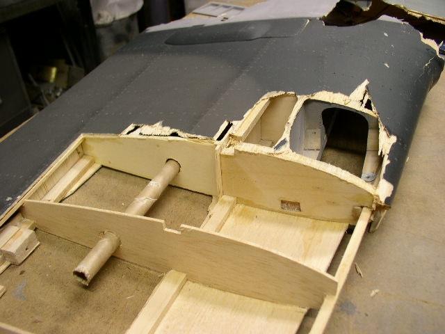
9 Upper side of left wing panel from the front. Note pop thru of aileron servo and the missing center section

10 This is the underside of left wing tip. The aileron servo bay is also visible.

11 Underside of right wing panel. Note missing center section.

12 Bottom view of missing leading edge of right wing panel.
13

14 Most of what s left of the wing spread out on the table after returning from the field. Note collection of grass and many miscellaneous parts. Fritz the pilot survived. He sits patiently awaiting for his ride to be rebuilt.

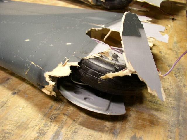
15 Fuselage as viewed from head-on. The engine had the crankshaft driven thru the back of the case. Almost all the fins on the fan were sheared off in the impact. As you can see, the spinner is a bit flattened. The fuse has a definite twist to it now, mostly because the front and back are almost separated from one another.
16
17

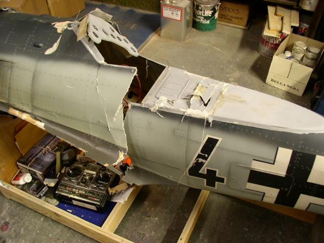
18 Fuselage as viewed from the top of the fin The only parts that will be re-used from this view are the dash panel and the pieces laying on the floor to the right. All of these will get cleaned up and reused. Fritz will be happy to see familiar surroundings when he finally climbs back in..
19

20 Note that all of the landing gear mounting area has survived but the wheel well area is in need of some first aid

21 This is the right panel and here again all of the landing gear mounting area has survived but the wheel well area is missing altogether.

22 Top side view of right wing panel. The lower spar survived but the upper one did not. All the ribs were split so they were removed and will be replaced with new ones. Note that there is a sizeable portion of the bottom sheeting missing also. The wing tip block survived but was removed and will be reused. A new leading edge will also be installed as well as some new top sheeting.

23 Top side view of right wing panel. The right panel now has the new ribs installed along the lower spar. The new leading edge spar is also in place. Almost ready to install the top spar. The sheeting laying on the bench on the right will be re-used.
24

25 The bottom of the old sheeting still has the aileron servo mounts and top spar attached. This spar will be spliced into the remaining spar.
.")
26 Bottom side of right wing panel. New leading edge in place but not trimmed yet. Most of the old sheeting has been striped from the bottom. The flap has also been removed to replace a few broken hinges. Note that the spar is still missing toward the bottom of the picture. (toward the center of the wing). Stay tuned for the next few pictures

27 Top side of right panel with old sheeting in place. The leading edge will get trimmed and shaped before the new sheeting is added. Then our attention goes back to the bottom sheeting.

28 Bottom of right panel. A good portion of the old sheeting has been removed and the lower spar has been cut back and removed well past the landing gear mounting area. The new spar will go all the way to where the center rib will be. The servo seen is for the flap on this panel.

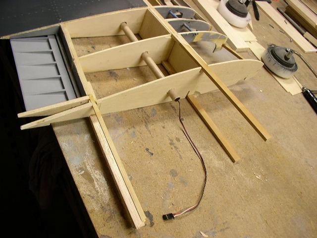
29 Top of right panel with new ribs numbers 1 and 2 and dihedral braces and top spar splice trial fit in place.

30 Top of right panel with new ribs numbers 1 and 2 and dihedral braces and top spar splice trial fit in place. Note that the outboard leading edge is shaped ready for new top sheeting.

31 Bottom of left wing panel. As you can see, not too much survived to be reusable. Almost all of the sheeting has been removed and discarded. However somehow the top and bottom spars survived from just inside the landing gear mounts all the way to the tip. The tip even managed to stay on and the flap and aileron are untouched also. The portions of broken ribs seen here will all be removed and replaced with totally new

32 Another view of the bottom of the left wing panel. The flap and its servo are still in-place.

33 Top side of left wing panel. Ribs Number 1 and 2 missing along with a whole bunch of sheeting.

34 Top side of left wing panel. Ribs Number 1 and 2 missing along with a whole bunch of outboard ribs and sheeting. This panel will receive the same kind of treatment as the right panel.

35 Trial fit of the two panels to establish the dihedral. Still one rib and some spar material missing.

36 The splice that is seen here will be doubled up on the inside with 1/16 aircraft ply running between the two ribs.

37 Bottom of left wing panel with new top and bottom front and rear spars spliced in place with a new rib number 2.
38

39 Bottom dihedral brace glued and clamped.
40

41 Top dihedral brace now glued and clamped.

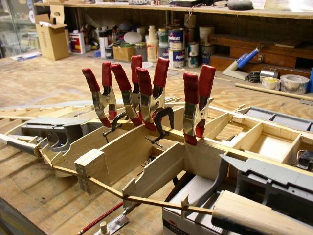
42 The wing is blocked up under each wing tip to provide the proper dihedral angle. Then the top dihedral brace is glued and clamped. The rear spars are also in place and glued at this time. Also note that the leading edge supports are also in place and glued at this time.

43 At last, a one piece wing.. All the servo mounts have been restored and all linkages have been redone. Working with the sheeting off make all the alignments and fiddling much easier. All that is left now is to close things up with some new sheeting.
44

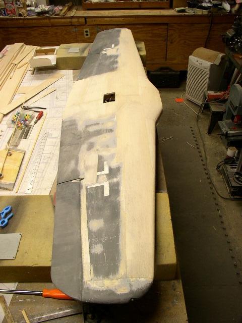
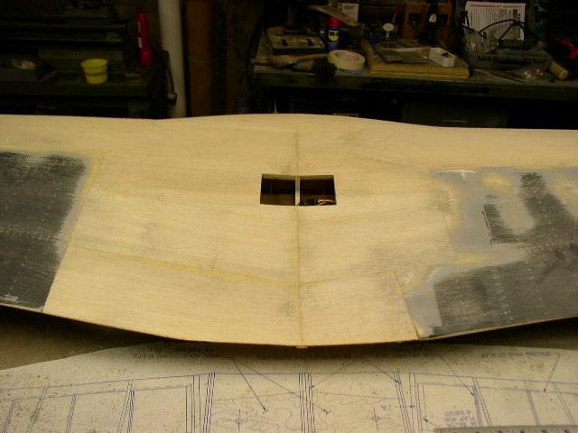
45 Top of wing. All of the sheeting in place and sanded to shape. Hurray! Just a little bit of sanding left to do on the right panel. Cut-out in the center is the exit for the servo wires. All the old sheeting has also been partially sanded. All the paint will eventually be removed and the entire wing re-glassed.
46

47 Top of wing. For those building the fiberglass fuse version, it s very important to sand this area correctly so that the wing sits fully in the pre-shaped wing saddle of the glass fuselage. You ll also need to remove some of the fuselage in this area.
48

49 Now that the top of the wing is all sheeted I can move on to the bottom. All servo are in place and there operation verified. The rib in the center of the wheel well area still needs to be trimmed. In this view you can also see the balsa doublers on the center rib to accept the wing dowel.

50 Bottom of the wing all sheeted. Again. Hurray! All servo hatches have been cut and some of the landing gear area has also been prepared. Once the gear is re-installed into the wing the wheel well areas will be cut to suite. Both wing tips in place and blended into the new sheeting.

51 Ah yes, the fuselage. What a mess First step was to separate the front from the back. The front will be scraped but the back will be trimmed and re-used.

52 The aft end separated. This will get trimmed further to prepare it for splicing to a new forward section.
53

54 Front section.. Almost every thing here is scrap. The servos will be rebuilt and the dash will be salvaged but everything else is garbage
55

56 Aft end trimmed further. All the rudder cables and elevator push-rods are re-usable.

57 All cables etc still good. The fiberglass still needs to be trimmed further to the black line around the inside of the fuse.

58 Trimming to the black line will give a good straight and even edge for bonding to the new forward section.

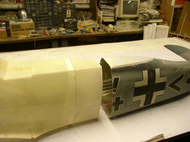
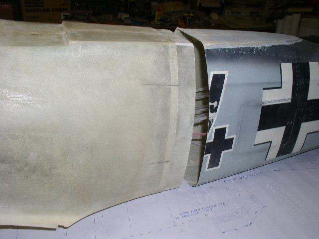
59 The rough trimmed old aft end along side the new fuse. The new fuse is marked at the aprox location of the joint. Both new and old parts will be adjusted as we get closer.

60 The trimmed old aft end now has a neat and straight edge to butt up against the new forward fuse after it is cut.

61 The new fuse trimmed to allow for plenty of adjustment room. This also allows the old part to be slid over the new for rough measurements.

62 The tiller arm in my left hand is connected to the rudder and tail wheel using pull-pull cables. This will get a short push-rod that will go to the rudder servo after all things are back together.
63

64 The old aft end placed over the new forward end. Dimensions are taken from a new fuse to compare to the grafted set-up. This will tell me exactly where the real cut needs to be on the new forward section. Right now the mock-up is about 1/2 inch too long. Compare the end of the rudder post..

65 The forward section trimmed to the real location.

66 The piece in the center will become the splice stiffener. It will also aid in alignment of the old aft end. This splice will be inserted inside the forward section and epoxied in place before the aft end is added.

67 The splice in place ready for the aft section.
68

69 Mating complete.. All alignments checked and double checked prior to gluing. All looks well.

70 The pieces in the fore-ground are what s left of the new fuse. These will be discarded or the in-tact aft end will be made into a wall hanging. Mission complete! Now on to installing all the new innards.

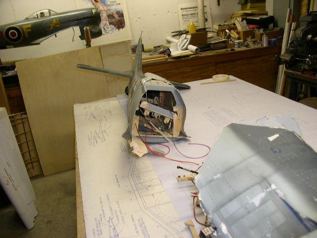
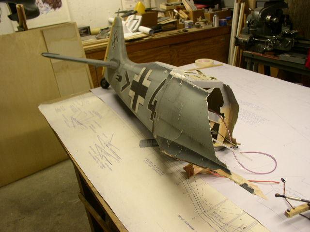
71 The original cable and pushrod set-up fit right into place. They will be right in line for the new servo mounts etc. Also note where the air-fill and pressure indicator are installed. The two airlines toward the bottom of the picture run to the tail wheel retraction cylinder. The airline near the clamp at the top will run from the fill valve etc to the air storage tank. The storage tank will be located toward the forward area of the fuselage ahead of the dash panel.


72 The old gun hood was salvaged and used to make a mold for production parts. This is the A-5 / F-2 version.

73 These are the two parts that will make up the recessed laminated firewall to accommodate a Zenoah GT-80.

74 Laminated firewall ready for installation. This will set the engine back into the fuselage by ½ inch.

75 Zenoah GT-80 installed with the fan also mounted. Everything fits very nicely.

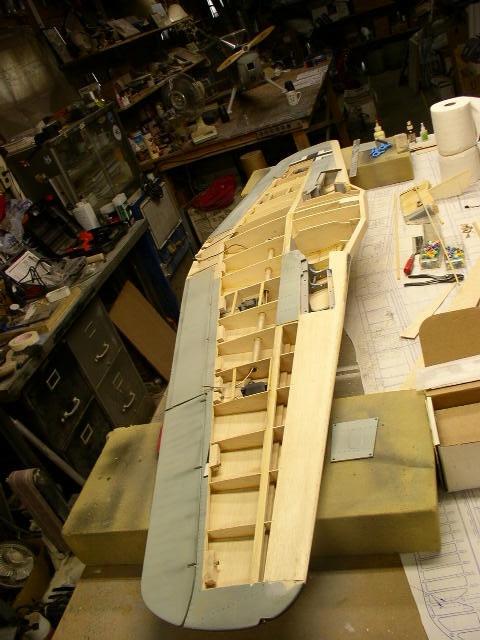
76 At last Standing on it s own three feet for the first time since June The engine is installed and the landing gear is temporarily installed just to get some sense of progress. On to finishing! See part 2!
Insanity is doing the same thing over and over again and expecting a different result
 ZIROLI P40 KITTYHAWK Insanity is doing the same thing over and over again and expecting a different result I have built four Ziroli Kittyhawks over the past umpteen years and this is a picture of the fourth
AVA Building Instructions
 Suggested Assembly Sequence: AVA Building Instructions 1. Insert fittings in rudder and trial fit rudder on boom 2. Attach stab to v-mount and position ahead of rudder ¼, sanding the v-mount as needed.
Building Instructions ME 163 B 1a M 1:5 Turbine
 Building Instructions ME 163 B 1a M 1:5 Turbine Thank you for choosing our kit of the Me-163B. We ask you to read the instruction once in advance before building this kit in order to avoid mistakes. Make
aero naut Electric Model Aeroplane Quido Order-No. 1303/00
 aero naut Electric Model Aeroplane Quido Order-No. 1303/00 Quido is a small model that accompanies you wherever you go. The prefabricated parts are mostly balsa and just need to be assembled according
Dornier Do R 4 Super-Wal
 Dornier Do R 4 Super-Wal Model Aviation Laddie Mikulasko s Dornier Do R 4 Super-Wal Build the multiengine, record-setting seaplane. Article, plans, instructions, and photos by Laddie Mikulasko. Complete
1/10 th Scale 1956 Ted Jones Classic Hydroplane
 1/10 th Scale 1956 Ted Jones Classic Hydroplane Preparation These plans show outside sheeting of 3/32 balsa laminated with 1/64 birch ply. This makes a light and strong skin for this boat. Optionally you
Model Aero Sportster Indroduction
 1 Model Aero Sportster Indroduction We are excited to introduce the Model Aero Sportster! Inspired by classic designs of the past, the Sportster is a relaxing slow flyer, equally at home indoors or outside
Akcent-2 - Building Instructions
 Akcent-2 Home Pictures Building Instructions Ordering Akcent-2 - Building Instructions Note! The pictures show older kits with "diser" wings. The new kits come with nicer D-box wings. Servo locations are
PAY N PAK, 1/12 th Scale, Limited Sport Hydro P Sport Hydro
 1980 82 PAY N PAK, 1/12 th Scale, Limited Sport Hydro P Sport Hydro Introduction: The 1980 turbine Pay N Pak is a good subject for a model race boat. It has a low profile, mild pickle-fork setback, long
Miss Mayflower. Build Manual
 Miss Mayflower Build Manual Thank you for the purchase of the Miss Mayflower, this new exciting craft will give you fun on many types of terrain including snow, gravel, pavement, grass, water, and when
Addiction Review by David Boyd
 Addiction Review by David Boyd Hi, I m Dave the guy flying the purple Addiction in GOT AN ADDICTION-The Movie. When PA asked me to do this Review I said I d love to. But I am just an average pilot and
Horizontal Fuselage. Top Vertical Fuselage 1. Lay out the Top Vertical Fuse Front(1), Top Vertical Fuse Back(2), and Vertical Stabilizer(3).
, Top Vertical Fuse Back(2), and Vertical Stabilizer(3).") Rumbuilder 71 B-17 Congrats on your Rumbuilder B-17! We re glad you chose to fly with us! If you have any problems, or missing/broken kit pieces, please contact us. We d be happy to replace any damaged
Rumbuilder 71 B-17 Congrats on your Rumbuilder B-17! We re glad you chose to fly with us! If you have any problems, or missing/broken kit pieces, please contact us. We d be happy to replace any damaged
Aegea Assembly Notes:
 Aegea Assembly Notes: The Aegea model is a thermal Duration (TD) model made up of components from Phil Barnes 1 (bagged wing and tail group) and Terry Luckenback 2 (Pretty Mantis fuse). Due to its construction
Southern Eagles Soaring
 Southern Eagles Soaring N56LS Standard Cirrus Disassembly / Assembly Procedure. Version 2, 2017 You landed out so what now? First, hopefully you made arrangements with someone who has a hitch on their
Model Aero AT-6 Texan Introduction
 1 Model Aero AT-6 Texan Introduction We are excited to introduce the Model Aero AT-6 Texan! Originally used as an advanced trainer by the U.S. Armed Forces, the AT-6 is a relaxing slow flyer, equally at
BASIC AIRCRAFT STRUCTURES
 Slide 1 BASIC AIRCRAFT STRUCTURES The basic aircraft structure serves multiple purposes. Such as aircraft aerodynamics; which indicates how smooth the aircraft flies thru the air (The Skelton of the aircraft
FlyingFoam Nurf. General Assembly Instructions
 FlyingFoam Nurf General Assembly Instructions These instructions apply to the Nurf, an all EPP forward swept flying wing available from FlyingFoam.com. Building and operating a remote controlled aircraft
Annex E(M) - Final inspection checklist - monowheel
 - Final inspection checklist - monowheel") Annex E(M) - Final inspection checklist - monowheel A/C Reg... Owner...Kit S/N...Date... (U.K. Only) L.A.A No...Inspector...Insp. No... Note: This check list only covers specific items for inspection of
Annex E(M) - Final inspection checklist - monowheel A/C Reg... Owner...Kit S/N...Date... (U.K. Only) L.A.A No...Inspector...Insp. No... Note: This check list only covers specific items for inspection of
Instructions for Fun Foam Critter 4/25/2007 BP Hobbies LLC 140 Ethel Road W Suite J Piscataway NJ,
 Instructions for Fun Foam Critter 4/25/2007 BP Hobbies LLC 140 Ethel Road W Suite J Piscataway NJ, 08854 http://www.bphobbies.com Specifications: Wing Span: 20" Length: 20" Flying Weight: 5.5-7.0 oz Controls:
We hope you ll enjoy the Drifter as much as we have! Scott DeTray Model Aero Specifications:
 We are excited to bring you the Drifter RC airboat. You re probably thinking it doesn t fly so what is Model Aero thinking??? We have always liked RC vehicles of all types and have had a fondness for airboats
EPP Version Building Notes Updated
 EPP Version Building Notes Updated 12-10-2013 The Zulu covers a wide range of flying conditions: slope soaring in light to strong lift, thermalling, aerobatics, discus launches, and combat; for skill levels
Pre-Paint>Fuselage>Empennage>Fit vertical tail fin. Objectives of this task: Materials and equipment required: Fit the spar extender
 Pre-Paint>Fuselage>Empennage>Fit vertical tail fin Objectives of this task: To fit the vertical tail fin to the fuselage, including fitting the static probe, static tube, optional strobe light wiring and
ANGEL 2000 glider ARF ASSEMBLY MANUAL. Specifications: MS: 129
 WWW.SEAGULLMODELS.COM ASSEMBLY MANUAL ANGEL 2000 glider Graphics and specifications may change without notice. MS: 129 ARF Specifications: Wingspan---------------78.7 in ( 200cm). Wing area---------------582.8sq.in
"Aircraft setup is a constant process really. Every
 The R/C Aircraft Proving Grounds - Aerobatics Setup Set Up for Success by: Douglas Cronkhite "Aircraft setup is a constant process really. Every time something is changed, there is the chance it will affect
Miles M-57 Aerovan. Ok so on with the build.
 Miles M-57 Aerovan Now it s been a few years since I have produced a design for Model World so young Mr Van Geffen decided I had sat on my laurels for too long and it was time to get the thumb screws out
ANATOMY OF FUSELAGE REPAIRS
 ANATOMY OF FUSELAGE REPAIRS The first part of this file is about doing a repair on the glassed-over fuselage. The latter part covers some repairs on composite fuselages. The glassed-over fuse will stand
BUIDLING INSTRUCTION GLIDER MINI-RACE. MINI-Race building instruction January
 Wingspan [mm]: 950 Aspect ratio: 7,7 Wing area [dm2]: 11,7 Wing loading [g/dm²] : 16 Takeoff weight [g]: 190 Airfoil: AG03 mod BUIDLING INSTRUCTION GLIDER MINI-RACE www.pcm.at 1 CONTENTS DATA 1. Kit contents
TANDY WALKER'S 2 nd A CLASS BOMBER-30 to 40 FW: 30 Class A Bomber Silked Vertical Tail
 TANDY WALKER'S 2 nd A CLASS BOMBER-30 to 40 FW: 30 Class A Bomber Silked Vertical Tail The two pictures below shows the three vertical tail components before and after the first layer of silk covering
Designed by Steve Shumate Adapted from the North Star design by Laddie Mikulasko. Polaris EX Introduction
 1 Model Aero Polaris Designed by Steve Shumate Adapted from the North Star design by Laddie Mikulasko Polaris EX Introduction We re excited to introduce the Polaris EX seaplane parkflyer! Based on the
On the Wing... By Bill & Bunny Kuhlman,
 On the Wing... By Bill & Bunny Kuhlman, bsquared@themacisp.net Redwing XC, Part 4 August 2008 29 After nearly a year of work, our Redwing XC has finally taken wing. At the end of the last installment we
FUN-FLY MISSION; DART-LIKE STABILITY
 FUN-FLY MISSION; DART-LIKE STABILITY by BLAINE STETLER Kenny Martin, 11, pilots his Notforsale. (Photo by Jeff Tibbetts.) Below: left to right: Kenny Martin (kneeling), 11, of Summerfield, FL; Scott Roddenberry,
CONSTRUCTION NOTES BY: MARK HUNT ISSUED:
 INSIGHT V4 CONSTRUCTION NOTES BY: MARK HUNT ISSUED: 3/22/06 Pg.1 INDEX Title Page 1 Index 2 Introduction 3 Material list 4 Foam Cutting Notes 5 Wing 5 Stab 8 Vertical Fin 8 Fuselage Foam Parts 9 Fuselage
CARL GOLDBERG PRODUCTS LTD.
 CARL GOLDBERG PRODUCTS LTD. P.O. Box 818, Oakwood, GA 30566 678-450-0085 Fax: 770-532-2163 www.carlgoldbergproducts.com copyright 2003 Carl Goldberg Products, Ltd. WARNING! THIS IS NOT A TOY! THIS IS NOT
Sunbird 60 (1.5 Meter) Instruction Manual
 Instruction Manual") Sunbird 60 (1.5 Meter) Instruction Manual Who is that ugly bar-steward? Sunbird is a CNC machine moulded, CAD designed slope model aircraft. This plane has had a development period of over 2 years, and
Sunbird 60 (1.5 Meter) Instruction Manual Who is that ugly bar-steward? Sunbird is a CNC machine moulded, CAD designed slope model aircraft. This plane has had a development period of over 2 years, and
REPLACING THE AFT RUDDER CABLES
 REPLACING THE AFT RUDDER CABLES Note: You must have the assistance of a qualified Aircraft Mechanic to perform this procedure. A logbook entry with the mechanics signature is required. Please read these
8-GUN CORVETTE ASSEMBLY INSTRUCTIONS
 8-GUN CORVETTE ASSEMBLY INSTRUCTIONS THE HULL STEP 1 Fasten the Deck to the Hull. Find the hull. This is a large, pink, ship-shaped piece of insulating foam board. This will form the base of your model
IVAN S LAKEMASTER BY IVAN PETTIGREW CONSTRUCTION NOTES
 IVAN S LAKEMASTER BY IVAN PETTIGREW CONSTRUCTION NOTES August 2015 The LakeMaster started out to be a scaled down version of Ivan s Seagull which has been a fantastic model for over 20 years. The Seagull
X-29 Canard Jet. A Simple Depron Foam Build.
 X-29 Canard Jet. A Simple Depron Foam Build. Two full sized X-29 s were built and the first flew in 1984. They were experimental aircraft, testing this unusual configuration of a canard jet with swept
CONSOLIDATED PBY-5 CATALINA MINI-CAT by Ivan Pettigrew Construction Notes
 CONSOLIDATED PBY-5 CATALINA MINI-CAT by Ivan Pettigrew Construction Notes After several years successfully flying a 102-inch span model of a Catalina using 16 cells to power two Speed 600 size motors in
Yes! It s the very first one with me holding it! Top picture is the incredible Greg Dakin flying another prototype (Photo from Kevin Newton)
") Vector III Instruction Manual Vector III is a CNC machine moulded, CAD designed slope aerobatics model aircraft. This plane has had a development period of over 20 years, and three separate models to evolve
Vector III Instruction Manual Vector III is a CNC machine moulded, CAD designed slope aerobatics model aircraft. This plane has had a development period of over 20 years, and three separate models to evolve
MICRO - DLG. This kit should only take 30 minutes to compile, very simple and quick.
 MICRO - DLG This kit should only take 30 minutes to compile, very simple and quick. You will need: Hot Glue ( small tip preferably ) Sharp razor blade Ruler a strip of strong fiber tape Thin nose Pliers
robart HOW-TO Series Model Incidence Meter
 robart HOW-TO Series Model Incidence Meter The term incidence is something of a misnomer since this highly versatile tool is capable of measuring or comparing angles other than incidence of a wing or tail.
SEADUCER BOATS GAS MONO COME VISIT US ON THE WEB AT
 SEADUCER BOATS GAS MONO COME VISIT US ON THE WEB AT WWW.SEADUCERBOATS.COM 1 - Pkg. Of 440 push rod ends 1 - Pkg. of solder-on rod ends 2 -water outlet fitting 1-1/4" prop nut 1 -.250" x 24" flex shaft
DE HAVILLAND DHC-6 TWIN OTTER 600 BY IVAN PETTIGREW CONSTRUCTION NOTES
 DE HAVILLAND DHC-6 TWIN OTTER 600 BY IVAN PETTIGREW CONSTRUCTION NOTES Like the Sealand, Partenavia and Albatross projects, this model was designed to take advantage of the great efficiency obtained when
Your kit contains the following items. Additional Items You May Need. Pre- cut parts Propeller rigging and rubber Sandpaper Covering sheet
 Your kit contains the following items Pre- cut parts Propeller rigging and rubber Sandpaper Covering sheet The SkyFox offers great glide performance in a rubber powered plane due to its built up wing.
Pitts Model 12 Wing Leading edge Installation
 Pitts Model 12 Wing Leading edge Installation This procedure is used to install molded plywood leading edges included in the Pitts Model 12 kit. Nine (9) molded leading edge section are require per aircraft;
Main Wing Wood Parts
 Main Wing Wood Parts WR 1-11 TE LE MS1 MS2 ST MS3 Before you start the build, gather all the required main wing components. QTY o MS1 (Main Spar 1) 2 o MS2 (Main Spar 2) 2 o MS3 (Main Spar 3) 2 o ST (Servo
S A N S I B E A R S P L I N T 2 0 X
 SANSIBEAR SPLINT 20X This is just a short documentation of one way you can assemble the Cylon/Splint I'm sure the pics will speak for themselves. Good pictures are better than to many words. If you have
Steps for W17, W14,W07, Wing Assembly Sonex #815
 CAUTION: This document is in no way a publication of Sonex Aircraft LLC. or any other corporation. All products mentioned are not necessarily recommended for use, but are included for informational purposes
Tugster. Tug Boat. Competition or Sport Tug Kit. A Zippkits R/C Boat. Building Instructions
 Z I P P M A N U FA C T U R I N G Tugster Tug Boat Competition or Sport Tug Kit A Zippkits R/C Boat Building Instructions 2016 JMP Hobby Group St. Paul, Indiana 47272 www.zippkits.com Toll Free (866) 922-ZIPP
Bench Trimming A Stunt Ship
 Bench Trimming A Stunt Ship by Brett Buck "Bench Trimming" - this refers to setting up the initial trim of the airplane in the shop prior to flight. Since people have been flying stunt in its current form
Blazer Marine, Whiplash Sport Hydro
 Blazer Marine, Whiplash Sport Hydro Thank you for choosing to build the Whiplash Sport Hydro. We have spent over 12 years perfecting this design, and finally we are making it available to the world. We
So at 18%, the weight of our 50 Hawk should around the 8lb mark I ll let you know later if this was achieved.
 50 DUCTED FAN HAWK It was in 2015 when the first Hawk offering was made to the readership of the RCM&E and it proved to be a great success especially when we made the ducted fan installation a lot simpler
BUILDING INSTRUCTION Glider TASER unplugged. Taser unplugged Building instruction September
 Wingspan [mm]: 2000 Takeoff weight [g]: From 400 Airfoil: AG 455ct-02f AG47ct-02f by Mark Drela BUILDING INSTRUCTION Glider TASER unplugged www.pcm.at 1 CONTENTS DATA 1. Kit contents 2. What else do you
Service Bulletin 70. Subject: Vertical fin cracks. Applicability: All Sportsman aircraft
 Subject: Vertical fin cracks Applicability: All aircraft Issue: Inspection of the vertical fin and aft fuselage bulkheads B and C, repair of vertical fin and bulkheads and reinforcement of vertical fin
1939 STOUT TROPHY WINNER
 1939 STOUT TROPHY WINNER This model's 36-minute flight won the Stout Trophy and qualified the builder as captain of the American Moffett team. Bob Toft. Has won a second in gas, first in rubber at Nationals.
Constitution Instructions
 Constitution Instructions This kit will build a 1:48 scale hull for the USS Constitution frigate. The kit contains the following parts. 1/8 deck with laser etched deck lines 1/8 railing Ribs Center keel
SECTION 23iS/U: SIDE SKINS
 SECTION 23iS/U: SIDE SKINS F-1203G-R BULKHEAD SIDE CHANNEL F-01248-R-1 ARM REST F-01205D SEAT BACK ADJUSTMENT GUIDE, 4 PLACES F-01205B-1 ROLL BAR ATTACH PLATE, F-01248B-1 FUSELAGE PIN LATCH, F-01204J BULKHEAD
Related Careers: Aircraft Instrument Repairer Aircraft Designer Aircraft Engineer Aircraft Electronics Specialist Aircraft Mechanic Pilot US Military
 Airplane Design and Flight Fascination with Flight Objective: 1. You will be able to define the basic terms related to airplane flight. 2. You will test fly your airplane and make adjustments to improve
CIRRUS AIRPLANE MAINTENANCE MANUAL
 RUDDER 1. GENERAL The rudder provides airplane directional (yaw) control and includes a rudder trim tab used for yaw trim adjustment. The rudder is of conventional design with skin, spar and ribs manufactured
Star 45 Short Kit Build by Bob Szczepanski
 Star 45 Short Kit Build by Bob Szczepanski An old used Star 45 showed up at our pond one day last Fall. Nostalgia struck and I was hooked! A flood of memories sailing an International Star boat on Lake
CIRRUS AIRPLANE MAINTENANCE MANUAL MODELS SR22 AND SR22T CHAPTER 55-40: RUDDER GENERAL. Rudder 55-40: RUDDER. 1. General
 CIRRUS AIRPLANE MAINTENANCE MANUAL Rudder CHAPTER 55-40: RUDDER GENERAL 55-40: RUDDER 1. General The rudder provides airplane directional (yaw) control and includes a rudder trim tab used for yaw trim
Outbound Progress Report
 Outbound Progress Report 7-11-17 Tank Install The new 20 plus gallon fuel tank is underway. In a matter of weeks we should be getting the first article and placing a first run order. The tank fits like
WHITE WOLF. X-ray View MID POWER MODEL ROCKET KIT BUILDING INSTRUCTIONS KIT SPECIFICATIONS:
 WHITEWOLF-38 PARTS LIST 1 - Nose Cone 1-17" Airframe 1-6" Motor Tube 3 - Aft Fins 3 - Forward Fins 2 - Centering Rings 1-15" Parachute 2 - launch lugs 1-12 Kevlar Shock Cord 1 - Motor Retention >>(screw/washer)
Rigging the Pitts by Doug Sowder, IAC #14590
 Rigging the Pitts by Doug Sowder, IAC #14590 Pitts not flying so straight anymore? Don t believe that a Pitts can fly hands-off? Maybe you need to set aside a Saturday and do some rigging. The maintenance
# " "'! ' $ '"!'"'!''!"!!='!!%!%''!" + '4! '!!$ '4) " '! )")!'!$ ""'!!
 '! ))!'!$ '!!") !"# $!! %&!'"%(!'!"'' '!!!!)! '* ' '$ '!! + "! '$ ',!'""!'! ) " "!+ %(!'# ')'-%.(&' '!!!$! '!)"'!"$ '!"'!!!!'/!'! '!"! 0!'+ 1 ' 2!"'!)+!'%!'!! $ #'' 1+!!!" )!"3 '!"! ''" $ 4 ' " $ )'!! ' '$ '#!"! $ '!,&5!'!
!"# $!! %&!'"%(!'!"'' '!!!!)! '* ' '$ '!! + "! '$ ',!'""!'! ) " "!+ %(!'# ')'-%.(&' '!!!$! '!)"'!"$ '!"'!!!!'/!'! '!"! 0!'+ 1 ' 2!"'!)+!'%!'!! $ #'' 1+!!!" )!"3 '!"! ''" $ 4 ' " $ )'!! ' '$ '#!"! $ '!,&5!'!
Ultrafly Focke- Wulf 190 No fewer than 40 different versions
 This version of the Butcher Bird offers easy flying and fine performance. Review by John Wheater Ultrafly Focke- Wulf 190 No fewer than 40 different versions of Kurt Tank s FW190 were produced. So, describing
Parkzone Vapor Repair tutorials
 Propeller replacement The propeller is held on by the threaded shaft. You will need to grip the shaft/cog with your fingers or some pliers and rotate the propeller anticlockwise when viewed from the front.
Trimming and Flying a Hand Launch Glider A basic and beginners guide by Kevin Moseley
 Trimming and Flying a Hand Launch Glider A basic and beginners guide by Kevin Moseley First and foremost, I am by no means a master at what I have done, or do, in hlg or the class. I am fortunate enough
L-23 Super Blanik Rigging (assembly/disassembly) Guide Maj Carl Kerns
 Guide Maj Carl Kerns") L-23 Super Blanik Rigging (assembly/disassembly) Guide Maj Carl Kerns The L-23 Blanik is a difficult Sailplane to rig (assemble). The wings are heavy and are secured via a single
L-23 Super Blanik Rigging (assembly/disassembly) Guide Maj Carl Kerns The L-23 Blanik is a difficult Sailplane to rig (assemble). The wings are heavy and are secured via a single
Moose Flutter Incident
 Moose Flutter Incident Overview On October, 4, 2011 there were four of us flying from Colorado to Hays, Kansas for a fly-in. It was a picture perfect day, with little wind and very little turbulence. Mid-way
Outbound Progress Report Choosing an Engine:
 Outbound Progress Report 14 10-25-17 Choosing an Engine: A new design starts with an engine choice, and for the Outbound that was the Titan 340. No doubt this will prove a very viable and well fitted engine.
V-Tail Flamingo. Included in Kit * Pre- cut balsa parts * Ballast weights * Diagram sheet * Sandpaper sheet
 V-Tail Flamingo Included in Kit * Pre- cut balsa parts * Ballast weights * Diagram sheet * Sandpaper sheet Additional Items You May Need * Wood Glue * Epoxy Glue * Sanding block * Hobby knife Overview:
INSTALLING YOUR CLC RUDDER
 INSTALLING YOUR CLC RUDDER These instructions are written to help you install the CLC rudder kit on your wooden kayak. The rudder can be fitted to your boat during construction or after completion. Please
STOL CH rd Edition Drawings, dated April 16, 2012 Summary of changes from Edition 2 Revision 1 to Edition 3.
 STOL CH 750 3 rd Edition Drawings, dated April 16, 2012 Summary of changes from Edition 2 Revision 1 to Edition 3. Page Date Drawing Title 75-G-0 04/12 Three View Drawing 1. Edition 3 75-G-1 04/12 Drawings
Surfboard Repairs Chapter 7
 Surfboard Repairs Chapter 7 The Complete Surfing Guide for Coaches - Bruce "Snake" Gabrielson Repair Problems Boards continuously get bumped, hit rocks, break fins, get dropped, and many other things that
WAR WING Ultimate Combat Delta
 WAR WING Ultimate Combat Delta Assembly Instructions BEFORE YOU BEGIN: Thank you for purchasing this plan set. The plans contained in this set were created after extensive testing and design modifications
5. Tailplane assembly
 5. Tailplane assembly Overview This section covers the fitting of your completed tailplanes to the torque tube assembly. Included is the insertion of the TP13 bushes in the inboard rib and the fitting
Last Revised 3/17/15 RMRC Mako
 Ready Made RC, LLC Assembly Instructions for: Last Revised 3/17/15 RMRC Mako Page 1 Thank you for purchasing the RMRC Mako! It is important to read the manual in its entirety before your maiden flight.
August HAPPY BIRTHDAYS Joesph Litosky - September 1 Robert Guienot - September 11 Edward Mickle - September 27
 AUGUST CLUB MEETING The next Wright Flyers club meeting will be on Saturday, August 25 at 12:00 Noon at the WF Field. MINUTES OF JULY MEETING There are no minutes; the meeting was cancelled. HAPPY BIRTHDAYS
Introduction. Have Fun Pat Morgan patsplanes.com. The cool paper airplane site!
 Folded Designs Introduction Since at least 1909 paper planes have been folded and flown and become addictive to the true fan. I have been folding paper airplanes for over 45 years and designing them for
ADVENTURES WITH. Both of my grandfathers fished, my dad fished, and. creating unique handles for custom rods. 22 RodMaker
 From RodMaker Magazine Volume 7 Issue #4 WOOD creating unique handles for custom rods ADVENTURES WITH story by Ray Jergensen photos by Les Jergensen 22 RodMaker Both of my grandfathers fished, my dad fished,
Max Bee. Part II: Building Max Bee Stunt News 8. lighter: the building of Max. all published.
 Max Bee Can you say Exotic? Igor s World Championship winning design has lots of interesting aerodynamics as well as interesting aesthetic design cues. I know, I know, the designing article about Max Bee
SEADUCER BOATS GAS SPORT HYDRO
 SEADUCER BOATS GAS SPORT HYDRO COME VISIT US ON THE WEB AT WWW.SEADUCERBOATS.COM 2 - Pkg. Of 440 push rod ends 2 - Pkg. of solder-on rod ends 2 -water outlet fitting 1-1/4" prop nut 1 -.250" x 30" flex
Mike Hungerford's notes on building Ron Caudillo's TOS Enterprise
 Ron Caudillo, designer of this model, has kindly given his approval for release of my redraw/repaint/rework of it. The colors chosen for the model are subdued approximations of the colors found on the
Step 1: Block sand the transom to remove the seam joint. The end result should be a flat transom without a ledge where the seam joint is.
 WhiplashGV Instruction Manual Email: Brian@Blazermarine.com Phone: 513-598-1769 Step 1: Block sand the transom to remove the seam joint. The end result should be a flat transom without a ledge where the
T&J Models R/C Model Designs By Jim Young 9356 Wendover Ct. Brighton, MI
 T&J Models R/C Model Designs By Jim Young 9356 Wendover Ct. Brighton, MI 48116 www.tnjmodels.rchomepage.com Gloster Meteor T.7 1/2 World s Oldest Operational Jet Jet Introduction The Gloster Meteor was
A Table Top Wind Tunnel You Can Build
 A Table Top Wind Tunnel You Can Build Basic principles of aerodynamics can be studied in the classroom with this simple, inexpensive wind tunnel. All you need to build it is some cardboard boxes, glue,
Ottawa Remote Control Club Wings Program
 + Ottawa Remote Control Club Wings Program Guide line By Shahram Ghorashi Chief Flying Instructor Table of Contents Rule and regulation Quiz 3 Purpose of the program 4 Theory of flight Thrust 4 Drag 4
The Amphibious Park / Pond Flyer
 The Amphibious Park / Pond Flyer by Arron Bates www.keyboardmonkey.com/twinkle BUILDING This building instruction is meant to guide you through a build that is slightly different to most builds. It s
Kari-Tek. Kari-Tek. Hydro Skeg Retro-Fitting Instructions. Instructions for retro-fitting of Hydro Skeg
 Kari-Tek Instructions for retro-fitting of Hydro Skeg A good knowledge of fibreglassing will be required to fit the Hydro Skeg successfully. When working with fibreglass and cutting the holes, safety glasses,
MiG-29 Scale EDF Radio Control model airplane
 MiG-9 Scale EDF Radio Control model airplane Wingspan : 45mm Model No : FF-D004 UNDER SFETY PRECUTIONS This radio control is not a toy! - lways keep this instruction manual ready on hand for quick reference.
A6M3 Zero CONSTRUCTION. WW II Japanese Aerial Samurai. THE WING The wing is a basic foam-core affair, sheeted with balsa. Retracts are an option, but
 CONSTRUCTION By Mark Rittinger A6M3 Zero WW II Japanese Aerial Samurai T The Imperial Japanese Navy s Type 0 fighter is probably the most recognized Japanese aircraft of World War II. Coming as a bit of
CONSOLIDATED PBY-5A CATALINA BY IVAN PETTIGREW CONSTRUCTION NOTES
 CONSOLIDATED PBY-5A CATALINA BY IVAN PETTIGREW CONSTRUCTION NOTES Before starting construction of the Catalina model, three decisions need to be made regarding options that are offered. The first is regarding
De Havilland 100 FB9Vampire
 De Havilland 100 FB9Vampire Well this is a first you maybe thinking, finally a model plan specifically designed for turbine. Your next question might be, why it has taken so long for this to happen. Well
PEARSE MONOPLANE IN QUARTER SCALE BY IVAN PETTIGREW CONSTRUCTION NOTES
 PEARSE MONOPLANE IN QUARTER SCALE BY IVAN PETTIGREW CONSTRUCTION NOTES 2003 Before starting construction some decisions need to be made regarding the wing. It could be built in one piece, but it is not
CARL GOLDBERG PRODUCTS, LTD. P.O. Box 818 Oakwood GA Phone # Fax #
 Superfloats 36 ARF WARNING A radio-controlled model is not a toy and is not intended for persons under 16 years old. Keep this kit out of the reach of younger children, as it contains parts that could
How To Build A Water Rocket
 How To Build A Water Rocket DESIGN AND DEVELOPMENT Brainstorm The first step in the design of a water bottle rocket is brainstorming. Brainstorming is a problem-solving technique that involves the spontaneous
BUILDING INSTRUCTIONS
 Z I P P M A N U FA C T U R I N G A Zippkits R/C Boat BUILDING INSTRUCTIONS 2010 Zipp Manufacturing Frankfort, New York 13340 www.zippkits.com Table of Contents Introduction 1 Engine Mounting 30 S E C T
SLR Missile Thunderboat
 J M P H O B B Y G R O U P L L C SLR Missile Thunderboat Zippkits R/C Boats BUILDING INSTRUCTIONS 2017 JMP Hobby Group LLC Indiana USA 1 Introduction Thank you for purchasing this kit. We are sure that