New Hampshire s Tidal Crossing Assessment Protocol
|
|
|
- Betty Henry
- 6 years ago
- Views:
Transcription


1 New Hampshire s Tidal Crossing Assessment Protocol Authors: PETER STECKLER 1, KEVIN LUCEY 2, DAVID BURDICK 3, JOANNE GLODE 1, SHEA FLANAGAN 1 1 THE NATURE CONSERVANCY, NEW HAMPSHIRE CHAPTER, 22 BRIDGE STREET, CONCORD, NH PSTECKLER@TNC.ORG, JGLODE@TNC.ORG, SHEA.FLANAGAN@TNC.ORG 2 NEW HAMPSHIRE DEPARTMENT OF ENVIRONMENTAL SERVICES COASTAL PROGRAM, 222 INTERNATIONAL DRIVE SUITE 175, PORTSMOUTH, NH KEVIN.LUCEY@DES.NH.GOV 3 UNIVERSITY OF NEW HAMPSHIRE, JACKSON ESTUARINE LABORATORY, 85 ADAMS POINT ROAD, DURHAM, NH DAVID.BURDICK@UNH.EDU July 14, 2017

 Coastal Program.")
, Hannah Blondin (NHDES Coastal Program), Michael Dionne (NH Fish and Game Department), Steve Couture (NHDES Coastal Program),")
, Doris Small (WA Department of Fish and Wildlife), Pad Smith (WA Department of Fish and Wildlife), Matt Urban (NH Department of Transportation) Cite as: Steckler, P., Lucey, K.")
2 Acknowledgements We express sincere gratitude to the individuals and organizations that contributed to this project, including those listed as Advisors and Contributors below. The stakeholder engagement section details the points in the protocol s development when advisors and contributors provided feedback and insights that played an invaluable role in shaping this final product. And thank you to the Davis Family Foundation for your support of the project. This project was funded, in part, by NOAA's Office for Coastal Management under the Coastal Zone Management Act in conjunction with the NH Department of Environmental Services (NHDES) Coastal Program. Thank you to NOAA and the NHDES Coastal Program for partnering with The Nature Conservancy (TNC) and providing essential support to the project. Tidal Protocol Advisors and Contributors: Sarah Becker (UMass Amherst), Hannah Blondin (NHDES Coastal Program), Michael Dionne (NH Fish and Game Department), Steve Couture (NHDES Coastal Program), Shane Csiki (NHDES, NH Geological Survey), Nicole Maher (TNC Long Island), Joseph McLean (Wright-Pierce Engineering), Slade Moore (Biological Conservation), David Patrick (TNC NH), Jessica Price (TNC Long Island), Doris Small (WA Department of Fish and Wildlife), Pad Smith (WA Department of Fish and Wildlife), Matt Urban (NH Department of Transportation) Cite as: Steckler, P., Lucey, K., Burdick, B., Glode, J., and Flanagan, S New Hampshire s Tidal Crossing Assessment Protocol. The Nature Conservancy. Prepared for the New Hampshire Department of Environmental Services Coastal Program, Concord, NH. Cover photos: Collecting the stream channel longitudinal profile at a Rye Harbor/Route 1A crossing in Rye, NH (top, TNC). High, mid, and low tide conditions at the downstream side of the Rye Harbor/Route 1A crossing (bottom from left to right, TNC).
3 Table of Contents Definitions:... i Introduction & Overview... 1 Stakeholder Engagements... 2 Management Objectives, Assessment Parameters, and Evaluation Criteria... 3 Desktop and Field Assessment Components:... 5 Assessment Parameter Data Collection and Management... 6 Equipment for Field Assessments... 6 Safety Precautions for Tidal Assessments:... 7 Assessment Parameters:... 9 Site Visit Details (field assessment) Low Tide Photos (field assessment) Crossing Type & Conditions (field assessment) Crossing Cross Section & Stream Longitudinal Profile (field assessment) Overview Establishing a Control Point Quality Control and Quality Assurance Process for Surveying Sites Requiring Multiple Level Setups Crossing Cross Section and Stream Longitudinal Profile Assessment Parameters Crossing Cross Section Survey Turning Points Stream Channel Longitudinal Profile Salt Marsh Vegetation (field assessment) Other Site Observations (field assessment) Infrastructure Management (desktop assessment) GIS-Based Crossing Information (desktop assessment) Landscape Position Channel and Pool Widths Salt Marsh Migration Potential Ecological Inundation Risk to the Roadway Inundation Risk to Low-Lying Development (Non-Transportation)... 43
4 Evaluation Criteria Crossing Condition Evaluation Tidal Restriction Evaluation Tidal Range Ratio Crossing Ratio Erosion Classification Tidal Restriction Overall Score Tidal Aquatic Organism Passage Tidal Range Ratio Salt Marsh Migration Evaluation Salt Marsh Migration Potential Vegetation Evaluation Vegetation Comparison Matrix Infrastructure Risk Evaluation Inundation Risk to the Roadway Inundation Risk to the Crossing Structure Adverse Impacts Evaluation Inundation Risk to Low-Lying Development (Non-Transportation) Draft Overall Crossing Evaluations Infrastructure and Ecological Scores Overall Combined Crossing Score Data Processing Data Management File Structure and Outputs Data Processing Methodology Conclusion and Next Steps: Next Steps Literature Cited Appendix A: Tidal Protocol Field Form Appendix B: Wetlands and Deepwater Habitats Classification... 71
5 Definitions: Brief definitions are provided below for a selection of technical terms and acronyms that are referred to in the Tidal Protocol. 1% Annual Flood: The flood event having a 1-percent chance of being equaled or exceeded in any given year. The 1-percent annual chance flood is also referred to as the base flood or 100-year flood. From FEMA Backsight: A survey reading looking backwards to a turning point from a subsequent level setup location (see Foresight definition below and Figure 4). The backsight is taken from a subsequent level setup location after a foresight was collected on the same position from a previous level setup location. Ceiling of Crossing Structure: The high point inside of the crossing structure. This is where you d bump your head (at the highest point for a round, elliptical, or arch) when crossing through the structure (see Figure 5). Downstream: The seaward side of a tidal crossing. Foresight: A survey reading taken on a turning point position looking forward from the initial level setup location (see Figure 4). A foresight is collected when multiple level setup locations are needed to complete the crossing cross section and stream longitudinal profile. It relates the elevations of positions collected from the initial level setup location to those collected from subsequent level setup locations. HWI: Stands for high water indicator. High water indicators are physical features (water stains or wrack) at the crossing structure that indicate high water elevations (see Figure 5). Invert: The low point inside of the crossing structure, or the interior bottom of the crossing structure. MHHW: Stands for mean higher high water. The average of the higher high water height of each tidal day observed over the National Tidal Datum Epoch. From NOAA NAVD 88: Stands for North American Vertical Datum of A geodetic datum chosen to compare elevations so that elevation data can be consistent throughout North America. see NOAA SLAMM: Stands for sea level affecting marshes model. A model used to simulate potential impacts of long-term sea level rise on wetlands and shorelines. From NOAA SLR: Stands for sea level rise. The projected accumulation of ocean water volume associated with climate change that will cause sea levels to rise over time. Thalweg: The longitudinal line that runs along the deepest portion of a river channel. Turning point: A survey position used as a pivot between the initial level setup location and a subsequent level setup location (see Foresight, Backsight, and Figure 4). Upstream: the landward or inland side of a tidal crossing. i
6 Introduction & Overview New Hampshire s Tidal Crossing Assessment Protocol ( Tidal Protocol ) was developed to evaluate crossing structures that convey tidal flows. The Tidal Protocol is an assessment methodology used to inventory and prioritize tidal crossing replacements based on a set of management objectives, such as a structure s condition, inundation risk, and restrictiveness to tidal flows, among others. The Tidal Protocol is a first screen to identify infrastructure replacement and ecological restoration priorities; it is not designed to comprehensively assess tidal crossings to meet site-specific engineering and restoration requirements. Assessment protocols to address tidal crossings are few and far between. There is an abundance of freshwater road-stream crossing protocols, but they do not address the unique and complex nature of tidal crossings. The Tidal Protocol defines a tidal crossing as a culvert or bridge associated with a road, railroad, or other form of infrastructure that is influenced by the ebb and flow of tides. The need for the Tidal Protocol, which incorporates the latest coastal resilience focused geospatial datasets, is warranted for the following reasons: Tidal crossing infrastructure are at the front lines of coastal challenges associated with climate change, including sea level rise and more frequent and intense storm events. Climate-ready infrastructure is necessary to adapt to these challenges, allowing for the continuous flow of people, goods and services across our coastal communities Tidal habitats are special systems with complex hydraulics and hydrology. On average, tidal systems experience two high tides and two low tides every day and they pass, store, and transport significant volumes of water, salt and sediment Tidal systems are home to critically important and imperiled habitats and species that are adapted to life in these dynamic places, which are often subject to a broad range of salinities, water temperatures and ever-fluctuating water levels Tidal crossings are the gateways to upstream freshwater habitat for diadromous fish, and to spawning and nursery habitat for estuarine and marine species. They are also gateways for the migration of tidal habitats inland with rising sea levels, which are critical to support the array of fish and wildlife that depend on tidal marshes Careful consideration of upstream infrastructure and property susceptible to flooding is necessary in the assessment of tidal crossings both under current conditions and accounting for rising sea levels. For example, some existing tidal crossings may serve to protect inland communities by restricting tidal flows, but may also cause more severe flooding inland because of poor drainage seaward The Tidal Protocol was developed and informed by a broad group of coastal resource and transportation managers. It also incorporates assessment methodologies from other protocols that align with the Tidal Protocol s objectives. Specifically, we relied on The New Hampshire Stream Crossing Initiative AND Statewide Asset Data Exchange System (SADES) (NHDOT 2017) protocol for crossing type and condition assessment parameters, and on the Parker River (Purinton and Mountain 1996) protocol for evaluating tidal restrictions. While the Tidal Protocol was developed to meet coastal zone management needs in New Hampshire, it is intended to have much broader geographic applicability. Coastal resource managers from other states and regions, including Maine, Massachusetts, Rhode Island, Connecticut, New York, Washington State, and the Canadian Maritimes either contributed to the Tidal Protocol or 1
7 expressed interest in developing such a tool. As such, we are hopeful that the Tidal Protocol will be used beyond New Hampshire. We encourage other users of the Tidal Protocol to send suggestions for improvements and clarifications to the study authors listed on the cover page. This section of the Tidal Protocol lays out the background and framework upon which the protocol was developed. It also includes logistical information for the safe and successful deployment of the protocol. Following the Introduction and Overview, the Assessment Parameter section describes each of the protocol s assessment parameters and provides instructions for their data collection. An Evaluation Criteria section details the rational for the evaluation criteria and the methodology for calculating evaluation scores, followed by a Data Processing section that details methods for post processing the assessment parameters. Lastly, a Conclusion and Next Steps section concludes the Tidal Protocol and identifies some additional steps for advancement and outreach. Stakeholder Engagements Development of the Tidal Protocol benefitted greatly from strong stakeholder engagements. From the effort s kick-off meeting through the final field trials, multiple organizations and professionals participated in nearly every step of the protocol s development. Table 1 summarizes these engagements: Table 1. Details stakeholder engagements that occurred throughout the development of the Tidal Protocol including the engagement date, the type and description of the of the engagement, and organizations present. Date Type Engagement Description (organizations present) 7/28/2015 Technical meeting and site visits 9/10/2015 Tidal Crossing Assessment Workshop Initial discussion and site reviews considering management objectives and potential assessment parameters. (TNC, NHDES Coastal Program, NHDES NH Geological Survey, NH Fish and Game Department, UNH, Wright-Pierce Engineers) Information sharing about tidal crossing assessment efforts by over 40 coastal resource managers across and beyond New England. NH s efforts to develop assessment parameters and evaluation criteria were explored in-depth. Organized by the Northeast Regional Ocean Council (NROC), Gulf of Maine Council (GOMC), and the North Atlantic Landscape Conservation Cooperative (NALCC). (Casco Bay Estuary Partnership, CT Department of Energy and Environmental Protection, Fisheries and Oceans Canada, MA Coastal Zone Management, ME Department of Transportation, ME Natural Areas Program, ME Coastal Program, New Brunswick Department of Environment and Local Government, New Brunswick Department of Transportation and Infrastructure, NH Sea Grant/Cooperative Extension, NH Department of Environmental Services, National Oceanic and Atmospheric Administration, Nova Scotia Department of Environment, NY 2
8 Department of Environmental Conservation, RI Coastal Resources Management Council, The Nature Conservancy (NH & Long Island), University of Massachusetts Amherst, University of New Hampshire, US Environmental Protection Agency, US Fish and Wildlife Service, US Geological Survey, WA Department of Fish & Wildlife) Workshop Agenda at: Workshop Participant List at: 9/11/2015 Site visits Field review tidal crossings and discuss management objectives, assessment parameters and evaluation criteria (TNC, NHDES, WA Department of Fish and Wildlife) 6/22/2016 Field Trial First round of field trials, 2 sites (TNC, NHDES, UNH) 8/11/2016 Field Trial Second round of field trials, 4 sites (TNC NH & Long Island, NHDES, UNH, UMass Amherst) 9/7/2016 Field Trial Third round of field trials, 2 sites (TNC, NHDES, UNH, NH DOT, Wright-Pierce Engineering, Biological Conservation) 9/12/2016 Presentation Present and solicit feedback on draft protocol at the Northeast Transportation and Wildlife Conference, Lake Placid, NY (TNC) 10/27/2016 Presentation Present draft protocol to the NH Coastal Adaptation Workgroup, Portsmouth, NH (TNC, NHDES) 3/24/17 Presentation Present draft protocol at the NH Water and Watersheds Conference (TNC, NHDES) 4/5/2017 Workshop Present and solicit feedback at Using Technology and Emerging Practices to Improve Tidal Marsh Resilience. Organized by the Northeast Regional Ocean Council (NROC) and the North Atlantic Landscape Conservation Cooperative (NALCC). (Similar attendees as 9/10/2015 workshop). 5/30/2016 Field Trial Final field trial of final draft Tidal Protocol (TNC, NHDES, UNH) Management Objectives, Assessment Parameters, and Evaluation Criteria The framework of the Tidal Protocol is organized by a set of management objectives to help stakeholders (e.g. state and federal agencies, municipalities, NGOs) prioritize tidal crossings for improvement and/or replacement. A management objective in this context is the degree that a site 3

9 characteristic meets a certain management standard. For example, does the existing crossing meet the condition standard of good (i.e. is the crossing structure in good condition)? Or, does the existing crossing structure meet the standard of not restricting tidal flow? The protocol follows a three-step process to understand how each site ranks against each management objective (see Figure 1). First, a set of assessment parameters are used to measure site specific crossing characteristics. Assessment parameters are addressed both in the field and from the desktop. Field assessment parameters are collected on-site through quantitative and qualitative measures, while desktop assessment parameters are collected using local information (i.e. information collected from road managers) and a Geographic Information System (GIS). Second, evaluation criteria are applied to score a selection of the assessment parameters. Third, the evaluation criteria scores feedback to understand how each crossing ranks against the management objectives. The Tidal Protocol s management objectives are detailed in Table 2. Figure 1. Depiction of the feedback loop between management objectives, assessment parameters, and evaluation criteria, which make up the framework for the Tidal Protocol. 4
10 Table 2. A list of the management objectives that the Tidal Protocol addresses, including the management objective standard that respective evaluation criteria are measured against and an explanation of each objective s relevance. Management Objective Management Objective Standard Management Objective Relevance Crossing Condition Crossing is in good condition Understand the condition of tidal crossings to address safety and transportation infrastructure management Tidal Restriction Crossing does not restrict tidal flow Understand hydraulic compatibility of crossing structures with the tidal system Tidal Aquatic Organism Passage Salt Marsh Migration Vegetation Infrastructure Risk Adverse Impacts Crossing does not impede fish or other aquatic organism passage Crossing will not impede upstream salt marsh migration Crossing has no noticeable effect on upstream versus downstream marsh vegetation Crossing is climate-ready: it is not vulnerable to inundation currently and with 1.7 feet of sea level rise (i.e high emissions projection) Restoring full tidal range at the crossing will not adversely affect upstream infrastructure Understand the compatibility of crossing structures for fish and other aquatic organism passage Understand the upstream opportunity for salt marsh habitat to migrate inland with rising sea levels Understand the influence of crossing structures on the up and downstream plant community, which can indicate effects on hydrology, salinity, and sedimentation Understand the degree of risk at crossings, considering inundation risk and headwater buildup conditions Understand the likelihood of restoring full tidal range at a crossing given upstream lowlying infrastructure Assessment parameter instructions and evaluation criteria details are provided in their respective sections of this document. Desktop and Field Assessment Components: The Tidal Protocol includes desktop and field evaluation components to take full advantage of a variety of useful data sources. Desktop derived information is combined with site specific data that must be 5
11 collected in the field. The desktop component relies partly on the use of a GIS to access geospatial data layers; it also relies on transportation infrastructure managers to provide site specific crossing information. The following geospatial data layers are recommended to complete the desktop evaluations: Hydrography flow lines Public and private roads Watershed boundary for each crossing National Wetlands Inventory (NWI) using all E2EM% records High resolution orthophotography USGS topographic maps High resolution topography (e.g. LiDAR) A trained field crew should be able to complete the field assessment at most tidal crossings in approximately two hours. More complicated sites requiring multiple level setup locations to complete the longitudinal profile (because of steep road fill slopes or line of sight obstructions) will likely take longer. The field crew must plan accordingly, as site visits must correspond with low tide conditions. Visits to downstream (i.e. closest to the ocean) crossings need to be closely timed with low tide from the nearest tide chart; crossings further upstream will likely have a delayed and somewhat greater window of time at low-tide conditions. Assessment Parameter Data Collection and Management As of the protocol s publication date, desktop and field assessment data are captured in a Microsoft Excel based field data sheet (see field datasheet in Appendix A). Items in the Assessment Parameters section of the Tidal Protocol follow the order of items organized in the field data sheet, which groups field parameters and desktop parameters for efficient use. The Microsoft Excel field data sheet file includes three primary worksheets: (1) Data Sheet BLANK is a blank version of the Tidal Crossing data sheet, (2) Data Sheet SITE is the worksheet to enter site specific assessment parameters that feed into (3) Data Sheet SUMMARY, which is a template for summarizing site specific evaluation criteria and assessment parameters. These tools are still under development, and are detailed further in the Data Processing section. We intend to incorporate the Tidal Protocol s assessment parameters into ArcGIS Collector, Esri s mobile mapping application, for streamlined data collection and management prior to implementing the protocol in the Spring of A new set of reporting tools will be needed for that data collection and management platform. Equipment for Field Assessments Field evaluations are completed at each crossing site. The following list of equipment is required to complete the field evaluation: Datasheets, clip board, pencils (including extra copies of Page 2 for multiple structures at one crossing) Digital camera Tape measure (300 in decimal feet) with weight attachment for depth measurements and to anchor for longitudinal profile 6
12 Level survey instrument, tripod, 25-foot leveling rod in decimal feet Mallet/Hammer and wooden survey stakes Machete/Loppers to remove obstructing vegetation Chest waders Safety equipment: Personal flotation device, sun block, water, insect repellent Cell phone First aid kit Boat (e.g. small kayak) for sites with deep pools Vegetation species identification field guide, e.g. A field Guide to Coastal Wetland Plants of the Northeastern United States, Ralph W. Tiner, Before attempting to complete a tidal crossing assessment, it is critically important to understand your equipment and how to use it properly. Review the calibration protocol for your level instrument, and make sure you understand how to read elevations from the leveling rod (including the sequence of extending rod sections). Also, make sure that you consistently collect your measurements in decimal feet units. Safety Precautions for Tidal Assessments: The field crew s safety and the safety of the public at large is paramount, much more important than collecting every parameter of the protocol. Do not collect any parameter that puts you or others at risk. Below is a summary of some of the known safety risks and precautions that should be taken: Traffic: some assessment parameters will be collected in the roadway, and the field crew will likely need to cross the road to complete a site assessment. Wear a reflective safety vest and do not collect features that put you or motorists at risk. If it is a high-volume road follow the protocol instructions to collect alternate features, if needed The longitudinal profile collects elevations using a telescoping leveling rod up to 25 feet high. Be aware of overhead utility lines and take care not to collect any features that potentially puts the rod in contact with overhead utilities Follow wader safety guidelines, including: o Wear a personal flotation device o Move slowly to stay in control and minimize falling; expect slippery conditions o Beware of mucky substrate that you may sink into, uneven footing, poor visibility into the water, and variable water currents o Use the leveling rod as your third point of support. Always maintain two points of contact as you move. In deeper areas, test depths with the leveling rod to make sure you don t overtop the waders o Use of a wading belt is mandatory if you fall over it keeps water from flowing into the legs and boots of the waders, allowing for easier escape from the river o Walk forward, not backward. Find stable footing around rocks and boulders rather than stepping on slippery high points o Use common sense- do not wade into an area that is clearly too deep or where water velocities are too fast 7
13 o Use caution when entering a stream crossing structure. Be alert for hazards on the ceiling, uneven footing, and increased flow velocities in the structure. Never enter a structure without another person watching for your safety Marine clay, which is inevitable and abundant in tidal habits, is extremely slippery. Slippery conditions exist within the stream, along the stream banks, on the salt marsh, and along the road fill slope. Use caution when moving around and through these slippery conditions New Hampshire s salt marshes are lined with historic ditches, some fairly small and some deep and wide. Ditches can be grown over and present a hidden tripping or falling hazard. If you can t easily step over a ditch, or navigate across the ditch easily, walk around the ditch or to a point where you can easily step over. Take care when pushing off and landing, as ditch edges can be slippery, slough off, and be hidden under droopy tall grasses Be prepared for biting insects. Consider wearing long sleeved clothes and using insect repellent. Check closely for ticks after each field day Coastal roadsides and upland salt marsh edges are often infested with poison ivy. Take care to identify poison ivy and avoid contacting it, especially if you are allergic Many tidal crossing sites are exposed, with limited shading and relief from the sun. Be prepared with sunscreen, ample water, sunglasses and a hat 8
14 Assessment Parameters: This section provides descriptions of the Tidal Protocol s assessment parameters and instructions to collect them. Assessment parameters are used to measure site specific crossing characteristics; they are collected both in the field and from the desktop. Field assessment parameters are collected on-site through quantitative and qualitative measures while desktop assessment parameters are collected using local information (i.e. information collected from road managers) and GIS. The order of the assessment parameter descriptions and instructions follows the order of assessment parameters organized in the field data sheet (see Appendix A). The field data sheet includes multiple sections broken out by group; these groups are organized to maximize data collection completeness and efficiency. The groups of assessment parameters include: Site Visit Details (field assessment) Low Tide Photos (field assessment) Crossing Type & Condition (field assessment) Crossing Cross Section and Stream Longitudinal Profile (field assessment) Salt Marsh Vegetation (field assessment) Other Site Observation (field assessment) Infrastructure Management (desktop assessment) GIS-Based Crossing Information (desktop assessment) The following table is a template that details how the assessment parameter name, location, description, list of attributes, and description of attributes are presented throughout this section of the protocol. Not every parameter consistently fits into this template; however, instructions are provided for each parameter to ensure that field assessment teams have the information needed to conduct assessments consistently. Parameter Name List of multiple assessment locations (e.g. Upstream, Downstream) List of assessment parameter attributes (in many cases this will be a list of pre-defined selection options; in others, it will be a list of attributes to collect) Parameter description Descriptions of assessment parameter attributes 9
15 Site Visit Details (field assessment) This section provides details about the site visit including who completed the assessment, the site location, when the assessment was completed, and tide cycle information. Crossing ID Predetermined unique identifier for each assessment site. Observer(s) & Organization Record all those involved in the field assessment and their organization or affiliation (e.g. volunteer, student). Municipality City or town where the crossing occurs. Stream Name Stream name as identified by the New Hampshire Hydrography Dataset (NHHD) program. Road Name Road name from the New Hampshire Department of Transportation roads data layer. Date Record the date that the field assessment was performed on (mm/dd/yyyy). Start Time Time that assessment started (hh:mm AM/PM). End Time Time that assessment concluded (hh:mm AM/PM). Tide Prediction These fields are intended to collect information from the nearest tide chart for the day of the field assessment. Fields include: 10
16 Time Elevation Tide Chart Location Record the predicted time of high and low tides from the nearest tide chart (hh:mm AM/PM) Record the predicted elevation of high and low tides from the nearest tide chart Indicate the name of the tide chart location used for the Time and Elevation parameters General Assessment Notes Provide any general notes about the site visit and assessment. For example, document recent precipitation, encounters with landowners (and their names), etc. Low Tide Photos (field assessment) Photographs are collected to document the appearance of the crossing structure and the associated stream and tidal system. Photographs are especially useful during data processing and verification, and are essential for data quality control. Instructions are modified from NHDOT (2017). Photo File Names 1 View of upstream opening 2 Upstream view from above structure 3 Downstream view from above structure A minimum of four photos are required at low tide. Indicate the Photo File Name in the datasheet table for each of the respective photos required as detailed below and in the photo point illustration (Figure 2). Be sure to include scale in your photos, such as a person or a survey rod, especially when photographing the structure openings (photos 1 & 4). Photograph the upstream opening of the structure. The photo should be taken a reasonable distance upstream from the structure with the widestangle setting. If site conditions permit, include the roadway approaches, the land adjacent to the channel, armoring features (e.g. riprap, if present), and any other notable or relevant assessment features. Positioned above the upstream side of the structure, photograph the upstream stream system, including the land adjacent to the channel upstream of the crossing. Positioned above the downstream side of the structure, photograph the downstream stream system, including the land adjacent to the channel downstream of the crossing. 11
, and any other notable or relevant assessment features.")
17 4 View of downstream opening Photograph the downstream opening of the structure. The photo should be taken a reasonable distance downstream from the structure with the widest-angle setting. If site conditions permit, include the roadway approaches, the land adjacent to the channel, armoring features (e.g. riprap, if present), and any other notable or relevant assessment features. Additional spaces are available for additional photos. Photograph any other features or parameters from the field form that you feel might be questioned later, or a feature that you have uncertainty or questions about. Take additional photos if necessary to characterize the system and structure. Note the photo file and describe the photo. Figure 2. Sample illustration of photo point locations and photo directions for the four required photo points. Photo Comments Provide any relevant comments regarding the photos captured. 12

18 Crossing Type & Conditions (field assessment) The crossing type and condition assessment characterizes the crossing structure and its components including the collection of crossing structure dimensions. The condition of the crossing structure and its components are also assessed, including assessments of scour that can compromise a crossing s structural stability. Many of the assessment parameters and attributes are borrowed or modified from NHDOT (2017). Structure of at Crossing For crossings with just one structure, enter 1 of 1. For crossings with multiple structures, record the structure you are assessing (the first as 1, the second as 2 and so on) and the total number of structures at the crossing. For example, if you are assessing the second structure at a crossing with three structures total, enter 2 of 3. Typically, there is one structure per road crossing, but situations exist where multiple structures occur at one crossing site. Count all structures that are installed at or below the existing high water indicator. Do not count overflow structures or nearby structures carrying tributary or road drainage flows (i.e. those not installed to carry typical tidal flow). Crossing Type Select the most appropriate crossing structure type based on the options below. The required crossing dimensions are shown for the respective crossing type, which will be addressed in the Crossing Dimensions assessment parameter. Round Culvert A circular structure with a closed bottom Elliptical Culvert An oval structure with a closed bottom 13


19 Pipe Arch Culvert An oval structure with a closed bottom; the shape of the lower portion of the structure appears squashed Box Culvert A square or rectangular structure with a closed bottom, usually made of concrete or stone blocks Embedded Round Culvert A circular structure with a closed bottom; the bottom of the structure is buried by streambed materials Embedded Elliptical Culvert An oval structure with a closed bottom; the bottom of the structure is buried by streambed materials Embedded Pipe Arch Culvert A pipe arch structure (as described above) that s bottom is buried by streambed materials 14


20 Open Bottom Arch A semi-circular structure with an open bottom Arch-Bridge An arched bridge deck set on abutments with an open bottom Bridge with Abutments A relatively flat bridge deck set on abutments with an open bottom Bridge with Side Slopes A relatively flat bridge deck with angled side slopes and an open bottom; no abutments are visible or abutment height from side slopes are not measurable Bridge with Side Slopes & Abutments A relatively flat bridge deck set on abutments with angled side slopes and an open bottom. The side slopes extend from the abutments toward the stream channel Other Select Other if the crossing type is different from the available crossing type options. Provide a description in Crossing Type/Condition Comments 15
21 Structure Materials Identify the material listed below that best describes the construction of the crossing structure. Focus on the structure that conveys the stream beneath the road; headwall and wingwall materials are captured in subsequent assessment parameters. Concrete Stone Aluminum-Corrugated Plastic-Corrugated Steel-Corrugated Wood Plastic-Smooth Steel-Smooth Other Crossing Dimensions Upstream Downstream Dimension A Dimension B CB Dimension B LT Dimension C Dimension D Document the upstream and downstream structure dimensions as indicated in the diagrams provided in the Crossing Type section. Not all dimensions are required depending on the crossing type. Measure the interior width of crossing Measure height from the ceiling of the crossing structure to the channel bottom (in the thalweg) Measure height from the ceiling of the crossing structure to the low tide water level Measure width of stream channel at the break point between side slopes and the stream bed. For round or elliptical structures this is the embedded width of the natural bottom if exposed at low tide. For any crossing type other than box and round culvert, if the embedded streambed is submerged at low tide, measure the width of the channel at the low tide water elevation (see embedded elliptical culvert example). For Arch Bridge: Measure height from low tide water elevation (or exposed streambed elevation at low tide) to the start of the arch For Bridge with Side Slopes and Abutment: Measure height of vertical abutments from underside of bridge to where sides start sloping. 16


.")
22 Low Tide Perch Upstream Downstream Measure the upstream and downstream low tide perch in decimal feet, or indicate if not applicable (N/A). Low tide perch is measured as the invert s height above the immediate upstream or downstream channel, respectively, if all the following conditions are present: 1. There is a vertical drop between the invert and the respective upstream or downstream channel at low tide 2. The vertical drop creates a waterfall or cascading barrier feature that impedes aquatic organism passage at low tide 3. The respective low tide water elevation is below the invert elevation (i.e. the invert and the respective upstream or downstream channel is not covered by relatively flat low tide water) Low tide perch on the upstream side of the crossing is uncommon; it might present itself at sites where there is little or no flow at low tide or where flow is seeping underneath the crossing structure. Photo document the low tide perch in the Low Tide Photos section, especially if there is any question about what features to measure. Measure multiple features if necessary and collect photos indicating the different features measured (use the leveling rod to indicate the location of the measurement and to provide scale). Note: The longitudinal profile will capture the elevations of inverts and the upstream and downstream low tide water elevations (low tide water elevations should be taken where the water flattens out in the adjacent pool feature). The perch feature should also be captured in the longitudinal profile if it is present. High Tide Perch High Tide Water Elevation Measure the downstream high tide perch in decimal feet, or indicate if not applicable (N/A). High tide perch is measured as the invert s height above the downstream channel if all the following conditions are present: 1. There is a vertical drop between the invert and the downstream channel at high tide 2. The vertical drop creates a waterfall or cascading barrier feature that impedes aquatic organism passage at high tide 17

23 3. The high tide water elevation is below the invert elevation (i.e. the invert and the downstream channel is not covered by relatively flat high tide water) Since the assessment will occur around low tide, high tide perch can be calculated based on the difference between the downstream highwater stain indicator (MHHW) and the downstream invert elevation. Headwalls, Wingwalls, and Scour Parameters The following group of assessment parameters address upstream and downstream headwall materials, headwall condition, wingwall materials, wingwall condition, scour at structure, and scour severity. Complete the upstream assessment for all the parameters, followed by the downstream assessment. Figure 3 identifies the different structural components of a crossing structure, such as the headwall, wingwall, abutment, and footer. Figure 3. Schematic illustrating the headwall, wingwall, abutment, and footer of a crossing structure. Headwall Materials Upstream Downstream Indicate the material of the upstream and downstream headwalls. The headwall is a retaining wall installed parallel to the fill slope of the crossing to protect against scour and erosion around the openings of the crossing structure. Metal Continuous metal wall, such as sheet piling Concrete Preformed or cast in place concrete Masonry Mortared stone or brick Gabion Wire filled cages of rock or stone Riprap Loosely placed large stone, often angular Other Other material not listed. Specify in Crossing Type & Condition Comments section None No headwall present 18
24 Headwall Condition Upstream Downstream Select the option that best describes the overall condition of the upstream and downstream headwalls. Good Fair Poor N/A Headwall is intact and appears in good condition. Metal: surficial rust may be present Concrete: shows little or no sign of spalling/deterioration Masonry: mortar joints are intact and tight Gabion: cage is intact and shape is not malformed Dry Fit Stone/Riprap: materials are in place as expected when originally installed Signs of deterioration are present; headwall structure is still functional but will require maintenance in the near-future. Metal: rust is beyond surficial resulting in loss of wall thickness Concrete: consistent moderate spalling/deterioration of concrete is present (>¼, <3 ). Minor cracking may be visible Masonry: mortar joints are loose or missing but overall headwall shape has not malformed Gabion: cage is malforming or beginning to deteriorate Dry Fit Stone/Riprap: materials have shifted/eroded and are not fully supporting themselves around the structure opening; scour into the road fill slope is limited Significant signs of deterioration are present; headwall structure is failing and requires immediate maintenance. Metal: holes are widespread Concrete: consistent severe spalling/deterioration of concrete is present (<3 ). Rebar reinforcement or large cracks may be visible Masonry: mortar joints are missing and brick/stone material is falling out of place Gabion: cage is malformed and disassembling Dry Fit Stone/Riprap: materials have eroded and are not supporting themselves around the structure opening; scour is eroding into the road fill slope Headwall is not present to evaluate condition. 19
25 Wingwall Materials Upstream Downstream Indicate the material of the upstream and downstream wingwalls. Wingwalls are retaining walls installed adjacent to the headwall to direct flow into the crossing structure. They are often installed at an angle extending out/away from the road fill slope. See Headwall Materials section for descriptions of selection options. Wingwall Condition Upstream Downstream Select the option that best describes the overall condition of the upstream and downstream wingwalls. See Headwall Condition section for descriptions of selection options. If the wingwalls are separating from the headwall, indicate Wingwall Condition as Poor. Scour at Structure Upstream Downstream Identify the crossing structure component(s) that is compromised by scour (select all that apply). Scour results from the removal of materials (e.g. fine sediment, sand, gravel, cobble, or boulders) by flowing water. Indicators of scour can include: Exposed areas of a structure that are typically covered by stream bed material (e.g. bridge footings) Leaning or hanging (perched) structures Structure materials sloughing into the channel Water visibly flowing under or to the side of a culvert Deep water along one or both sides of a bridge or arch when the bed feature through the structure is a riffle Selection options include the following: None Footer Abutment Armoring Culvert Wingwalls Headwall Severity of Scour Upstream Downstream Select the severity of scour for the respective upstream and downstream features identified in Scour at Structure. The severity rank should reflect the most severely scoured structure component. None No scour is observed 20
26 Low Medium High Limited scour is present that presents no apparent threat to the crossing structure (e.g. finer material is no longer present) Noticeable scour is present. Left unmaintained, scour will continue to undermine and jeopardize the structure component Severe scour is present that jeopardizes the crossing component or crossing structure as a whole. Immediate maintenance is required Scour in Structure Identify the crossing structure component(s) that is compromised by scour inside the structure (select all that apply). Scour results from the removal of materials (e.g. fine sediment, sand, gravel, cobble, or boulders) by flowing water. See Scour at Structure for examples of indicators of scour. Selection options include the following: None Footer Channel Culvert Abutment Armoring Scour Severity in Structure Select the severity of scour inside the crossing structure for features identified in Scour in Structure. The severity rank should reflect the most severely scoured structure component. See Scour Severity for descriptions of selection options. Road Surface Condition Good Fair Poor Select the condition of the road surface for the road segment that bisects the wetland system. Road surface is in sound structural condition; slight rutting or thin cracks may be present but are not deep or widespread. Road grade is uniformly smooth Road surface shows signs of aging with moderate rutting, widespread cracking, loss of fine and coarse aggregate from the surface, patches, potholes (<2 ), or pavement edge deterioration Road surface is severely deteriorating or failing. Severe road surface distortion may be present such as heaves, ruts, or patches. Pavement is severely cracked or disintegrating with potholes prevalent. Road grade may be rough and/or bumpy 21
27 Structure Condition - Overall Good Fair Poor Identify the condition of the overall structure (inlet, pipe, outlet) based on the following rating criteria. Like new, with little or no deterioration, consistent shape, minor joint misalignment, no movement, structurally sound and functionally adequate Some deterioration or cracking, joint separation with minor infiltration but structurally sound, localized distortion in shape, functionally adequate Significant deterioration or extensive cracking and/or spalling, extreme deflection in shape, joint separation with potential to create voids, significant movement and/or functionally inadequate requiring maintenance or repair Sketch of Structure A sketch box is provided to illustrate and provide detailed dimensions of the crossing structure, especially if the configuration of the crossing structure differs from the dimensions included in the Crossing Dimensions section. If additional space and/or sketches are needed, sketch them on a separate sheet, photograph the sketch and document the photo(s) in the Low Tide Photos section. Crossing Type & Condition Comments Provide any additional comments about the crossing type or condition. Crossing Cross Section & Stream Longitudinal Profile (field assessment) The Crossing Cross Section and Stream Longitudinal Profile collects relative elevations of multiple site features (i.e. assessment parameters). These assessment parameters apply to multiple management objectives and evaluation criteria including tidal restriction, aquatic organism passage, and infrastructure risk. An overview of the survey methodology is provided followed by details about the cross section and longitudinal profile assessment parameters. Overview The Crossing Cross Section and Stream Longitudinal Profile collects relative elevations of features at the crossing structure and in the stream channel. A cross section of features at the crossing structure are collected, including the ceiling of the crossing structure, high water indicators, marsh surfaces, and road 22
28 surface elevations. The stream longitudinal profile captures the relative elevations and slopes of the stream channel and its features including pools, riffles, crossing structure inverts, and grade controls. The purpose of the longitudinal profile is to better understand the hydraulic performance of the crossing, its compatibility with the stream system, and the risk of flooding to the structure and roadway currently, and with sea level rise. A survey instruments that captures relative elevations is required to complete this evaluation. A laser level system or optical level with a tripod, field tape and leveling rod are basic survey equipment essentials. A trained field crew will need to evaluate and determine how best to execute and complete the longitudinal profile survey at each site because of the variability in conditions at tidal crossings. At a minimum, the field crew is likely to set up the survey instrument at the roadway (R) elevation to collect information about the road surface. In many cases the remainder of the elevation fields will be shot from the R setup. However, roads with considerable fill slopes or line of site obstructions to upstream and/or downstream features will require setting the level up upstream (U) or downstream (D) of the crossing to collect the remainder of the necessary elevation shots (see Process for Surveying Sites Requiring Multiple Level Setups section for more details). Each feature collected for the Crossing Cross Section and Stream Longitudinal Profile requires specification of the location from where the elevation was shot (i.e. R or U or D). This information is captured in the solid outlined box (g) to the right of each feature s elevation field on the Microsoft Excel based field datasheet. Establishing a Control Point Once the field crew sets up the level at its initial R location it is necessary to establish a control point at the site. A control point is a location of a feature that will not change in the foreseeable future and that is easily locatable in the near-future. The control point serves as a reference point for quality control in case the survey instrument inadvertently shifts during the assessment, or if the assessment team needs to re-visit a crossing site to collect missed or additional information without having to recollect the entire longitudinal profile to relate elevations to one another. To establish a control point, locate a relatively permanent surface beyond the road travel lanes that can be easily identified and described. A stable headwall, large stable boulder, or a point along the edge of the pavement are potential locations. Mark the location of the control point with a silver dollar sized dot of orange spray paint. This is the point that you will collect your control point elevation from at the beginning and end of the longitudinal profile survey and that you will need to describe the location of in the Describe Control Point field. Be as specific as possible in your description. For example, orange dot on center of downstream headwall or orange dot along upstream edge of pavement at the center of the crossing. Field crews with GPS capabilities should consider collecting the location of the control point. Quality Control and Quality Assurance Collecting the height of the established control point at the beginning and end of the longitudinal profile is an important quality control and assurance measure. If the elevations are the same, then there is assurance that the level instrument didn t shift during the survey and that collected elevations are properly referenced relative to one another. If the before and after elevations are different (>0.1 23
29 100 feet away) then the relative elevations of the longitudinal profile might be inaccurate. Re-stabilize and level the instrument and recollect the elevations for the features in question. Also, a somewhat common mistake when using a leveling rod is to have different sections of the rod improperly extended or extended out of sequence. This leads to erroneous height measurements. To properly use a laser level compatible leveling rod with a laser level make sure to extend the top most section to its desired length (elevation). If multiple sections of rod are necessary, make sure to extend the top section of the rod until fully extended, then extend the next highest section of rod to the desired height, or fully extend before extending the next highest section (and so on). Make sure that all lower sections of rod are not extended until needed. Read the elevation from the back of the rod; take the reading from the top of the smallest unextended section. Note: when using an optical level the rod must be fully extended from the bottom most section first, followed by fully extending the next lowest section, and so on. Process for Surveying Sites Requiring Multiple Level Setups The characteristics at some sites will require setting up the survey instrument at multiple locations to collect the necessary elevation shots to complete the cross section and longitudinal profile. This might occur at crossings with very high fill slopes where the road surface is significantly higher than the stream channel, or at locations where line-of-sight obstructions, such as dense vegetation, prevent the collection of elevations with a level instrument. A 25-foot surveyor s leveling rod is recommended to maximize the elevation range of the longitudinal profile from a single level setup location. A 25-foot rod will allow for the collection of elevations up to 25 feet below the level instrument; elevations of longitudinal profile features greater than 25 feet below the instrument will require setting the instrument up at additional locations upstream and/or downstream to collect those features. It is necessary to develop a well thought out plan to execute an efficient cross section and longitudinal profile where multiple level setups are needed. An example is provided in Figure 4, which illustrates three level setup locations and the turning point foresights and backsights required to relate elevations between them. Consider the location of your roadway level setup (the first place where the level is setup) in relation to your other potential level setup locations and turning points. You will need to establish or identify turning points (detailed further in step 5 below) and collect their elevations to relate the elevations from your roadway level setup to your upstream and/or downstream (secondary) setup(s) through a series of foresights and backsights (detailed further in steps 6 and 9 below, respectively). Consider potential line of sight obstructions when selecting turning points, such as structures or vegetation between your roadway level setup and turning point, as well as your secondary setups and turning points. Also, consider the elevation range limitations when determining turning points. If you are using a 25-foot leveling rod your turning point elevation must be within a 25-foot vertical range of the roadway level setup, and the secondary level setup must be higher than the elevation of the turning point. Below are general steps to complete a longitudinal profile at a site that requires three setup locations for the level, including a roadway, upstream, and downstream location: 1. Review the crossing site layout and identify the location of the roadway level setup, turning point locations, and upstream and downstream level setup locations. Make sure that there are no visual obstructions between the respective level setups and the turning point locations. 24
 features, ceiling of the crossing structure, and high marsh elevations upstream and downstream of the crossing as possible. 4.")
30 2. Setup the level at the roadway. Establish and collect the elevation of the control point, road centerline at the center of the crossing, and road surface elevations. 3. Collect as many of the high-water indicator (HWI) features, ceiling of the crossing structure, and high marsh elevations upstream and downstream of the crossing as possible. 4. Starting from upstream, collect as many of the upstream and downstream longitudinal profile features as possible from the roadway level setup, including the low tide water elevation, if it is within the vertical range of the leveling rod and not limited by line of site obstructions. a. If it will be easier or more efficient to collect all the upstream and downstream longitudinal profile features from their respective upstream or downstream level setups, disregard step Establish upstream and downstream turning points. A turning point can be a stable, permanent or semi-permanent feature that will relate elevations between the roadway level setup and the respective secondary level setup. A large boulder, ledge, or headwall could serve as a turning point. For these features, spray paint a half dollar sized orange dot onto the feature at a flat surface or high point where the point s elevation will be taken. If no such feature is available drive a wooden survey stake into the ground at the desired turning point location until it is firmly in place and the elevation at the top of the stake is satisfactory. The top of the stake will be the turning point elevation. a. In many cases the turning point is different from the established control point. In some cases, the control point can be used as the turning point if it is within vertical and line of sight range of both the roadway and the respective secondary level setup. 6. Once the necessary turning points are established, collect the elevation (foresight) of the upstream and downstream turning points from the roadway level setup. 7. Re-collect the height of the established control point for quality control and assurance purposes. If the control point elevation is less than 0.1 feet different at a distance of 100 feet away, continue to the next step. If not, repeat steps 2 through 7 8. Reposition the level instrument to the upstream setup location 9. Collect the elevation (backsight) of the upstream turning point 10. Collect elevations for the remainder of the upstream longitudinal profiles features, low tide water elevation, HWI features, ceiling of structure, and high salt marsh elevations. Verify that all upstream features are collected. 25 Figure 4. Illustration of a site with three level setups, including the Roadway (R), Upstream (U), and Downstream (D) locations. Also shown are the turning points and the turning point foresights and backsights required to relate elevations between three level setups.
31 11. Re-collect the backsight elevation of the upstream turning point. If the backsight turning point elevation is less than 0.1 feet different at 100 feet away, continue to the next step. If not, repeat steps 9 through Follow steps 8 through 11 to complete the cross section and longitudinal profile for the downstream side of the stream crossing. Crossing Cross Section and Stream Longitudinal Profile Assessment Parameters Following are the assessment parameters, descriptions, list of attributes, and instructions for the crossing cross section and stream longitudinal profile. Height of Established Control Point Measure the height of the established control point in decimal feet. Establish the control point at an easily identifiable, describable, and relatively permanent surface beyond the road travel lanes. A stable headwall, large stable boulder, or a point along the edge of the pavement are potential locations. If no such feature is available drive a wooden survey stake into the ground at a desired control point location (away from the roadway) until it is firmly in place and the elevation at the top of the stake is satisfactory. In this case the top of the stake will be the control point elevation. Mark the location of the control point with a silver dollar sized dot of orange spray paint; this is the point where you will collect the control point elevation. Describe Control Point: Describe the location of the established control point. Be as specific as possible in your description. For example, orange dot on center of downstream headwall or orange dot along upstream edge of pavement at the center of the crossing or wooden survey stake driven into north western quadrant of salt marsh 20 from road edge. Height at Road Centerline Traffic and safety permitting, collect the elevation of the road centerline at the center of the crossing structure in decimal feet. This parameter is collected as a reference point to tie the longitudinal profile into high resolution topographic information. The centerline of the road at the crossing structure is an easy feature to identify using high resolution orthophotography. Note the location of a different reference point used in the Comments field, if applicable (applies especially to high volume roads where surveying the centerline is dangerous). For alternative locations, attempt to use a broad flat surface that can be located on an aerial photo. For example, higher volume roads typically have a white stripe differentiating the travel lane from the breakdown lane. Collecting 26

32 the elevation of the white stripe centered over the up or downstream side of the crossing structure alignment is an option. Low Tide Water Elevation Upstream Downstream Collect the upstream and downstream water level elevations at low tide in decimal feet. It is important to make sure that these elevations are collected as close to low tide conditions as possible. Collect the water level elevation at pooled or standing water elevations beyond any grade control features associated with the crossing. Crossing Cross Section The following group of assessment parameters captures elevations of features that can be used to generate a cross section of the crossing (e.g. an elevation profile perpendicular to the road). Features to collect include upstream and downstream high water indicators (HWI) for stains and wrack lines, the ceiling of the crossing structure, the road surface, and salt marsh plain elevations. Figure 5 depicts a selection of these features. Collection of these features are grouped together in the datasheet because they can be collected out of sequence with the Stream Channel Longitudinal Profile (these features can be collected well before or after low tide). Figure 5. Examples of a selection of crossing cross section assessment parameters. HWI Wrack: the magenta arrow indicates the upper extent of wrack deposits above the headwall HWI Wrack HWI Stain HWI Stain: the blue arrow indicates the upper extent of the high-water stain. Collect the highwater stain elevation at the upper stain limit Ceiling of Structure Ceiling of Structure: the white arrow indicates the location of the ceiling of the crossing Not Shown: Road surface and salt marsh plain The Stream Channel Longitudinal Profile is best collected at low tide conditions, so prioritize its collection when constrained for time around low tide. Invert elevations are collected in sequence in the longitudinal profile, thus their absence from this section. Collect upstream and downstream elevations 27
33 for each of the features below, making sure to indicate the level setup where the elevation was shot from (specify R or U or D in the solid outlined box (g). HWI Stain Upstream Downstream Collect the elevation at the upper limit of the stain feature observed at or near the crossing structure in decimal feet (see Figure 5). HWI Wrack Upstream Downstream Collect the elevation at the upper limit of wrack or debris accumulations at or around the crossing structure in decimal feet. Wrack lines may include matted clumps of vegetation deposited along the road fill slope at high tide elevations. Finer vegetation and other debris may also cling to the headwall and inside the crossing structure; look for lines of such materials above the stain features (see Figure 5). Ceiling of Structure Upstream Downstream Collect the elevation of the ceiling of the crossing structure in decimal feet (i.e. where you d bump your head at the highest point when crossing through the structure see Figure 5). Road Surface Upstream Downstream Collect the road surface elevation at the lowest point where the road crosses the tidal system (including the salt marsh and adjacent floodplain). For this assessment parameter, road surface is defined as the edge of pavement elevation where the road is most susceptible to inundation. Marsh Plain Shots (1 through 4) Upstream Downstream A total of eight salt marsh plain elevations are to be collected in decimal feet, four upstream and four downstream. The purpose of collecting these elevations is to determine if the crossing structure has a noticeable influence on marsh subsidence (loss of elevation due to oxidation of peat) or accretion (i.e. the ability of the marsh to build in elevation with sediment deposition from frequent flooding). When identifying marsh plain locations, consider the following: Identify and collect elevations from marsh locations that are typical of the marsh system (whether high or low marsh) Where possible, collect marsh elevations on both sides of the channel 28
34 To collect representative elevations, avoid taking elevations within approximately 50 feet of one another The salt marsh plain is typically quite flat. Avoid locations where there are oddities in the terrain, such as near ditches, along or atop areas of historic fill such as berms, etc. The assessment team might need to identify marsh locations some distance beyond the crossing if the marsh directly adjacent to the crossing structure is altered, disturbed, or not present Where possible, key in on similar vegetation, such as Spartina patens, because it might be most competitive at a specific/consistent inundation regime both upstream and downstream that is valuable for comparison purposes Where possible, avoid locations where the marsh plain contains hummocks (small mounds of clumped vegetation) surrounded by hollows (lower unvegetated areas). This indicates that the marsh vegetation and marsh elevation is in transition (due to sea level rise). In these cases, the marsh is changing from high marsh to low marsh. If such conditions are widespread, collect elevations from the hummocks rather than the hollows, as the hummocks represent current and recent marsh plain elevations, while the hollows will represent future elevations once transitioned to low marsh. Comments Provide any additional comments or clarifications about the crossing cross section or stream channel longitudinal profile. Survey Turning Points At sites requiring multiple level setups (see Process for Surveying Sites Requiring Multiple Level Setups, above, and Figure 4), collection of turning points are necessary to relate the elevations collected from different locations. For example, if an upstream level setup is required you will need to establish an upstream turning point. Once established, collect the upstream foresight elevation of the turning point from the roadway level setup (record the value in the field corresponding to TP Foresight and US Height). Then move the level to its upstream location. From the upstream level setup location, collect the backsight elevation to the upstream turning point (record the value in the field corresponding to TP Backsight and US Height). Follow this procedure for downstream turning point foresights and backsights. 29
35 IF NEEDED US Height DS Height TP Foresight TP Backsight From the ROADWAY level setup, collect the upstream (US) turning point elevation in decimal feet From the UPSTREAM level setup, collect the upstream (US) turning point elevation in decimal feet From the ROADWAY level setup, collect the downstream (DS) turning point elevation in decimal feet From the DOWNSTREAM level setup, collect the downstream (DS) turning point elevation in decimal feet Stream Channel Longitudinal Profile The stream channel longitudinal profile captures elevations and attributes of stream channel features along the stream reach where the crossing occurs. These features are used to generate a profile based on distance and elevation measurements collected at specific features of interest, such as hydraulic controls, scour pools, grade controls, and crossing inverts, which are identified using feature codes. Streambed substrate is collected at each feature too. The first step in collecting the longitudinal profile is to identify an upstream starting point. The starting point should be at least two hydraulic controls upstream of the upstream pool. To locate the starting point, work your way upstream from the crossing and locate the high point upstream of the pool (this will be the second hydraulic control in the longitudinal profile survey). Continue heading upstream in the channel thalweg to locate the next notable channel high point, which will be the starting point. If the stream channel profile is fairly uniform upstream of the first high point encountered, continue upstream a distance approximately equal to the distance between the crossing structure and the first high point location to locate the starting point. The distance at the starting point is 0.0 feet. Anchor the end of a 300 tape at the starting point using a heavy weight or some other anchoring device. It is important that the tape remain securely anchored to accurately collect the longitudinal profile. Run the tape measure along the length of the channel thalweg from the starting point to an endpoint located two hydraulic controls below the downstream pool (or similar point based on distance as described above). Attaching a second tape may be necessary to cover the distance of the longitudinal profile, or the anchor point may need to be shifted downstream once the first section of the profile exceeds the length of the tape. The longitudinal profile characterizes the elevations and slopes of the stream channel and the crossing structure. Essential components of the longitudinal profile are shown in Figure 6, and include the following: Hydraulic controls are channel features that control the flow and depth of water Scour pools are erosional features above and below the crossing that can indicate incompatibilities of the crossing structure with the stream Grade controls include channel substrate hardening around the crossing structure to reduce scour and undermining of the structure. 30
36 Inverts are the low points inside of the crossing structure at the upstream and downstream openings. Invert elevations are important to understand the vertical alignment of the crossing structure with the surrounding tidal system. Channel bottom features can be collected to provide additional detail about the channel slope that are not characterized by the features listed above. For example, at a perched downstream crossing at low tide, collect the channel bottom elevation just downstream of the perched invert to characterize the degree that the crossing structure is perched above the downstream channel. HC (starting point) HC P GC I Longitudinal Profile Feature Code Abbreviations HC = Hydraulic Control GC = Grade Control P = Pool Bottom I = Invert CB = Channel Bottom GC HC HC P I Figure 6. An example of a stream channel longitudinal profile, including the features of interest and their codes. For the starting point feature of the stream channel longitudinal profile, and each feature to follow, collect the following information: Distance Collect the distance from the starting point along the tape measure in decimal feet. Height Collect the elevation of the feature in decimal feet using the survey instrument. Feature Code Identify the feature being collected using a feature code from the following list: HC P GC I CB Hydraulic Control Pool Bottom Grade Control Invert Channel Bottom 31
37 Substrate Specify the dominant substrate type using the codes provided below: Substrate Substrate Code Description/Size Clay/Silt C/S Smooth to touch, not gritty between fingers Sand S <0.007, (approximately 1/16 th of an inch or less) Gravel G (1/16 th of an inch to 2.5 inches) Cobble C (2.5 inches to ~10 inches) Boulder B (> ~10 inches, not ledge) Bedrock Bed Ledge Shot From (R/U/D) Specify the level setup location from where the elevation is collected: R U D Roadway Upstream Downstream QC Height of Established Control Point At the end of the longitudinal profile collect the elevation of the established control point. For sites with multiple level setup locations, make sure to re-collect the elevation of the established control point and turning point(s) before moving the level to a new location or completing the longitudinal profile. Collecting the height of the established control point at the beginning and end of the longitudinal profile is an important quality control and assurance measure. If the elevations are the same, then there is assurance that the level instrument didn t shift during the survey and that collected elevations are properly referenced relative to one another. If the before and after elevations are different (> feet away) then the relative elevations of the longitudinal profile might be inaccurate. Re-stabilize and level the instrument and recollect the elevations for the features in questions. 32
38 Salt Marsh Vegetation (field assessment) This section characterizes the upstream and downstream vegetation communities at a crossing. Vegetation communities are indicators of inundation regimes (i.e. high tide elevations) and water salinity. Comparing upstream and downstream vegetation communities provides information about the effect of a crossing on these site characteristics. Natural Community Classification Upstream Downstream Sparsely vegetated intertidal habitat Low salt marsh High salt marsh Marsh elder shrubland Coastal salt pond marsh/meadow Brackish marsh Brackish riverbank marsh Select the dominant upstream and downstream natural community at the crossing (adapted from Sperduto and Kimball 2011). Intertidal areas with sparse vegetation (e.g. rocky shores, intertidal flats) Marshes regularly flooded by high tide, and dominated by smooth cord grass (Spartina alterniflora). Typically, along banks of tidal streams and rivers, and occupying lower depressions and pannes on the marsh surface Marshes between mean high tide and the upland edge. Typically, occupies a broader flat marsh surface, and usually dominated by short clonal grasses including saltmeadow cordgrass (Spartina patens), spike grass (Disctichlis spicata), and black grass (Juncus gerardii). May include pannes or pools which may be sparsely vegetated or open water Tidal community dominated by the shrub marsh elder (Iva frutescens) Marshes that occupy a basin separated by the ocean by a cobble berm; basin is seasonally flooded with freshwater and periodically infused with salt water during storm events; water is brackish to slightly brackish Marshes along the upland edge of a salt marsh, influenced by overland or groundwater freshwater flow. High marsh vegetation may be intermixed with taller sedges, cattail, and Phragmites at edges Riverbank marshes that are flooded by seawater pushed in by the tides, which is diluted by freshwater flowing down rivers/streams draining the watershed above 33
39 Freshwater marsh Freshwater swamp Invasive dominant Marshes not flooded by seawater. Plant species can be very diverse, but are not adapted to salty environment. May include ferns, tussock sedge, arrow-heads, tearthumbs, and common three-square Shrub dominated wetlands not flooded by seawater. Plant species can be very diverse, and may include dogwoods, red maple, alder, and blueberries Marshes where the salinity cannot be predicted because invasive species adapted to both saline and fresh environments are dominant. Typically, common reed is dominant (Phragmites australis) Invasive Species Present Upstream Downstream Select the dominant invasive species present within the marsh plain upstream and downstream of the crossing, if present. If more than one invasive species is present, choose the most dominant. Indicate other invasive species present in the Comments box. Phragmites Narrowleaf cattail Perennial pepperweed Purple loosestrife Japanese Knotweed Comments Provide any additional comments about the natural community classification or the invasive species assessments. Describe observations of the following: Observations of Vegetation Die Back (due to salt water incursion or Expansion of Mudflat) Dead or dying vegetation, such as trees or shrubs around the salt marsh periphery, that indicate salt water incursion Salt marsh in transition, such as converting to mudflat, which might be observed in the following stages: o First, the marsh surface develops vegetated hummocks surrounded by unvegetated lower lying mud o The hummocks shrink in size and eventually collapse to the point where only a few or no hummocks remain and 34
40 the mudflat surface is several inches below that of the previous marsh or other existing marsh areas NWI Marsh Classification (from desktop evaluation) This parameter is auto-filled from the desktop assessment, see NWI classification immediately up and downstream of the crossing for details. Field confirmation (i) or correction of NWI classification If the NWI classification is correct, indicate with a check mark. If the NWI classification is incorrect, input the correct Cowardin classification (see Appendix B). Note in the Comments field (above) the reason for change. Vegetation Comparison Matrix Select the option most appropriate for the crossing site. First use the vertical axis to determine if invasive species are absent, prevalent, or present mostly on one side of the crossing. Then use the horizontal axis to determine if the up and downstream plant communities are the same, different but both tidal, or very different. Other Site Observations (field assessment) This section provides an opportunity to document other site observations from the field assessment relating to habitat condition, other infrastructure, fish and wildlife, low-lying infrastructure, ancillary uses and utilities at the crossing. Condition of Salt Marsh or Wetland Habitat Assess the condition of the salt marsh or wetland habitat. Select from the following condition categories: Good condition Habitat is natural and undisturbed Somewhat altered or impacted Highly altered or impacted Signs of degradation such as encroachment by invasive species, visible signs of human use and disturbance, or dieback of native vegetation Clear degradation such as invasive species, encroachments by surrounding land uses, sediment fill, dredging, dumping of waste, etc. 35
41 Other Infrastructure Note any infrastructure other than the roadway at the crossing that constrains the salt marsh or wetland habitat. Select from the following: N/A Other infrastructure not observed Berm Dike A flat strip of land, raised bank or terrace bordering a river, canal or other shoreline An artificial wall built to regulate or hold back water from a downstream body of water (such as to prevent flooding from the ocean) Ditch A linear excavation for the purpose of draining water Rip Rap Seawall Rip Rap or Revetment Rip Rap: A sloping but orderly organization of rock, concrete or stone. Unorderly rock, concrete, stone, rubble or other material used to allow for water containment or to protect shorelines and structures from erosion by the sea, rivers or streams An orderly, vertical structure made of concrete, wood, steel, rocks, or other materials that runs parallel to the beach at the land/water interface Comments Provide any comments about the salt marsh or wetland habitat condition, or other infrastructure assessments. Fish and Wildlife Observations/Comments Document any fish and wildlife observations at or near the crossing (e.g., eels, otters, resident birds such as osprey and heron using the tidal habitat) Observations of lowlying infrastructure visible from the crossing Note any observations of low-lying infrastructure visible from the crossing, such as residential or commercial structures, driveways, lawns, etc. Ancillary Uses at Crossing Provide details about other uses occurring at the crossing (such as swimming, fishing, boating, lobster trapping etc.). 36
42 Utilities at Crossing Note any utilities observed at the crossing (e.g. power lines, sewer pipes, buried utilities, etc.). Other Comments Provide any other comments about the crossing not captured in other sections of the assessment. Field Assessment End Time Time that assessment concluded (hh:mm AM/PM) Infrastructure Management (desktop assessment) This section captures infrastructure management information about the tidal crossing. For efficiency, the desktop evaluator might consider identifying all tidal crossings managed by the same department or municipality, creating a map of those locations, and scheduling a meeting with the appropriate staff to collect crossing information for all tidal crossings managed by a single entity. Person Contacted Name of person contacted to collect crossing information from. Affiliation Department/municipality that person contacted is affiliated with. Date Date of contact (mm/dd/yyyy). Age of Structure Year structure was installed or reasonable approximate. Site Identified in Haz. Mit. Plan? Is the crossing location identified in the town s hazard mitigation plan? 37
43 Replacement Plans Does the owner/manager of the crossing have plans for replacement? If so, provide details regarding target date, replacement objectives (e.g. reduce flooding, enlarge crossing) etc. History of Flooding Is there a history of flooding at the crossing location? Provide available details such as frequency of flooding, dates, damage costs, etc. Emergency Access or Evacuation Route Is the crossing used for emergency access or as an evacuation route? Other Comments Provide any other relevant crossing information, especially any maintenance issues identified. GIS-Based Crossing Information (desktop assessment) This section collects GIS-based information about each crossing, including landscape position, channel and pool widths, salt marsh migration potential, ecological occurrences, inundation risk to the roadway, and inundation risk to low-lying development. Landscape Position Landscape position assessment parameters capture information relating the tidal crossing location to its position on the landscape. Crossing Outlets Directly to (answer each of the following) Atlantic Ocean Subtidal Indicate whether the crossing outlets directly to the Atlantic Ocean and subtidal habitat. Does the crossing outlet directly to the Atlantic Ocean (select Yes or No) Does the crossing outlet directly to subtidal habitat (select Yes or No). Subtidal habitat includes an area dominated by open water at low tide (fringe salt marsh might be present) 38
44 Number of (answer each of the following) Downstream Tidal Crossings Downstream Tidal Restrictions Indicate the number of downstream and upstream tidal crossings and restrictions. This assessment might only be possible once all crossings are identified for the relevant watershed under evaluation. A tidal restriction is identified as any crossing with a Tidal Restriction Overall Score of 3. Number of downstream tidal crossings Number of downstream tidal restrictions Upstream Tidal Crossings Number of upstream tidal crossings Upstream Tidal Restrictions Number of upstream tidal restrictions Upstream (answer each of the following) Using StreamStats (online tool at or a GIS, delineate and calculate the crossing s upstream watershed area and the area of existing upstream salt marsh Watershed Area Calculate the crossing s upstream watershed area in square miles Salt Marsh Area Calculate the crossing s existing upstream salt marsh in acres. Use the latest available National Wetlands Inventory (NWI) mapping using E2EM% wetlands. Exclude impervious surfaces from the resulting upstream salt marsh area Watershed Land Use (answer each of the following) Use StreamStats Basin Characteristics or a GIS to generate percent land cover/use for the crossing s upstream watershed area % wet. Percentage of the crossing s upstream watershed that is wetland % for. Percentage of the crossing s upstream watershed that is forested % imp. Percentage of the crossing s upstream watershed that is impervious % dev. Percentage of the crossing s upstream watershed that is developed 39
45 Channel and Pool Widths Channel widths are measured to evaluate the compatibility of the crossing structure s width with the tidal stream it conveys. Pool widths are measured to evaluate the expression of a tidal restriction through the erosion/scour features that a tidal restriction typically creates. Channel Width Upstream Downstream Use high resolution aerial photos in ArcGIS, Google Earth, or an online web mapping application such as the NH GRANIT Coastal Viewer to measure the average upstream and downstream channel widths from 2 to 3 representative locations (round measurements to the nearest foot). Measure the channel widths beyond the extent of scour features associated with the crossing. Measure the width parallel to the flow direction; avoid measurements at sharp channel bends. Max. Pool Width Upstream Downstream Use high resolution aerial photos in ArcGIS, Google Earth, or an online web mapping application such as the NH GRANIT Coastal Viewer to measure the maximum upstream and downstream scour pool width rounded to the nearest foot. Measure the width parallel to the flow direction. The stream may be channelized with bank armoring and/or grade control features. In these situations, the erosion feature(s) may not express themselves immediately up and downstream of the crossing; they may occur beyond the armoring features. Channel and Pool Width Comments Provide any comments about the channel and pool width measurements, such as the date, source, and resolution of the aerial photo used. Salt Marsh Migration Potential Salt marsh migration potential is measured upstream of tidal crossings to understand the availability of upstream salt marsh expansion areas under the 1.7-foot sea level rise scenario by year The dataset intended for this assessment was developed using the Sea Level Affecting Marshes Model (SLAMM) tool (NHFG 2014). 40

46 Area of Potential Upstream Salt Marsh Migration Upstream Watershed Upstream Evaluation Unit Using a GIS application, calculate the potential upstream salt marsh migration area in acres for both the entire upstream watershed and the upstream evaluation unit as shown in Figure 7. Use the 1.7 SLR by 2050 SLAMM return with connectivity on for both assessment parameters. The following steps can be used to perform these calculations in ArcMap: Upstream Watershed: 1. Delineate the watershed upstream of the crossing and add the polygon file to ArcMap. This can be done manually using a USGS topographic base layer or the watershed can be delineated and downloaded using the online StreamStats tool 2. Clip the SLAMM return referenced above to the watershed boundary 3. Erase impervious surfaces (high resolution preferred) from the result of step 2 4. Clip national wetland inventory intertidal emergent wetlands ("ATTRIBUTE" LIKE 'E2EM%') to the watershed boundary 5. Erase the result of step 4 from the result of step 3 6. Add an acreage field to the layer resulting from step 5, then calculate the acreage and summarize the acreage. This is the area of potential upstream marsh migration for the entire upstream watershed Upstream Evaluation Unit: 7. Using the delineated entire upstream watershed from step 1 above, edit the upstream watershed by cutting the polygon along the lowest road feature in the watershed that crosses the watershed or the tidal system 8. Clip the result of step 5 above by the result of step 7 9. Calculate and summarize the acreage. This is the area of potential upstream marsh migration for the upstream evaluation unit Figure 7. A map differentiating the entire upstream watershed from the upstream evaluation unit. 41
47 Ecological Tidal habitats are uncommon ecological features that have a history of being highly altered and impacted by human use. Because of this history and their rarity in New Hampshire, tidal systems are extensively inventoried. The New Hampshire Natural Heritage Bureau (NHB) tracks rare, threatened, and endangered species, and exemplary natural communities. The National Wetlands Inventory (NWI) maintains remotely sensed boundaries of estuarine wetlands by wetland type. This information is useful to understand the ecological significance and characteristics of tidal crossings from other inventory efforts. Natural Heritage Bureau Element Occurrences Use ArcGIS to determine Natural Heritage Bureau (NHB) Element Occurrences (EOs) within 0.25 miles of the crossing, including federal and/or state rare, threatened, or endangered species, or exemplary natural communities. Summarize findings including G- and S-ranks, and date of last observation. If access to NHB is limited, contact NHB to request EOs within 0.25 miles of the crossing. NWI Classification Immediately Upstream and Downstream of the Crossing Upstream Downstream Identify the National Wetlands Inventory (NWI) classification for the areas immediately upstream and downstream of the crossing using ArcMap, NH GRANIT s Coastal Viewer, or the US Fish and Wildlife Service s Wetlands Mapper, found here: See Appendix B for the Wetlands and Deepwater Habitats Classification system. These assessment parameters are field verified in the Salt Marsh Vegetation section under the NWI Marsh Classification parameter. Inundation Risk to the Roadway Rising sea levels and storm events will adversely impact low-lying tidal crossings and associated transportation infrastructure. We use sea level rise (SLR) modeling results (NHFG 2014) to evaluate road surface flooding under the 1.7-foot sea level rise scenario by year 2050 for both mean higher high water (MHHW) and 1% annual flood hazard conditions. This information can be used in conjunction with field information from the crossing cross section assessment. Is the Road Surface at the Crossing Inundated at 1.7' SLR by 2050 (MHHW)? Use the 1.7 SLR by 2050 (MHHW) model return to determine if the road surface at the crossing will be inundated (select Yes or No). This data layer is available for viewing on the NH Coastal Viewer web mapping application, where it can also be downloaded for use in a desktop GIS. 42
48 Is the Road Surface at the Crossing Inundated at 1.7' SLR by 2050 with 1% Annual Flood Hazard? Use the 1.7 SLR by 2050 with 1% Annual Flood Hazard model return to determine if the road surface at the crossing will be inundated (select Yes or No). This data layer is available for viewing on the NH Coastal Viewer web mapping application, where it can also be downloaded for use in a desktop GIS. Comments Provide any comments about the inundation risk desktop assessment. Inundation Risk to Low-Lying Development (Non-Transportation) Tidal crossings are at the intersection of seaward and landward flowing water. Undersized or restricted crossing structures can protect upstream low-lying development by muting high tide elevations, allowing for development to occur or remain where otherwise it wouldn t. We use sea level rise modeling results (NHFG 2014) to evaluate the number of low-lying non-transportation infrastructure that might be affected (i.e. flooded) assuming no tidal restriction. Scenarios evaluated include the 1.7- foot sea level rise by year 2050 for mean higher high water and 2015 conditions with the 1% annual flood hazard. These evaluations allow for the comparison of future risk on a regular MHHW basis and current risk from severe storm events. Number of Upstream Infrastructure Impacts Associated with 1.7' SLR by 2050 (MHHW)? Use the 1.7 SLR by 2050 (MHHW) model return and high resolution aerial photography with digital tax parcels to count the number of parcels with low lying non-transportation infrastructure impacts (i.e. number of parcels with structures inundated or affected by inundation, such as limiting access via driveway flooding, lawn flooding, etc.). Using high resolution impervious cover data will also be helpful. If more than 20 parcels are affected by infrastructure impacts, input >20. Number of Upstream Infrastructure Impacts Associated with the 2015 SLAMM Return with 1% Annual Flood Hazard? Use the 2015 SLAMM with 1% annual flood hazard model return and high resolution aerial photography with digital tax parcels to count the number of parcels with low lying non-transportation infrastructure impacts (i.e. number of parcels with structures inundated or affected by inundation, such as limiting access via driveway flooding, lawn flooding, etc.). Using high resolution impervious cover data will also be helpful. If more than 20 parcels are affected by infrastructure impacts, input >20. 43
49 Evaluation Criteria Evaluation criteria are applied to a selection of the assessment parameters to score tidal crossings based on the set of management objectives in Table 2. The intent of the evaluation criteria is to understand how individual tidal crossings perform against each management objective. Applying the evaluation criteria is a first screen toward prioritizing crossings for replacement and/or restoration based on individual or collective management objectives. While not every assessment parameter feeds into evaluation criteria, every parameter is intended to enhance our ability to better understand a site remotely following the field and desktop assessments. The evaluation criteria thresholds described below are a framework for site prioritization based on the management objectives. The thresholds can be modified to further stratify or condense the classes based on any given set of tidal crossings. As a starting point from the established framework, all evaluation criteria meeting or exceeding a scoring threshold of 3 indicate causes for concern. The evaluation criteria are organized below by the following management objectives: Crossing Condition Tidal Restriction Tidal Aquatic Organism Passage Salt Marsh Migration Vegetation Infrastructure Risk Adverse Impacts Each evaluation criteria includes a description of its relevance to the management objective and a description of the evaluation process. Crossing Condition Evaluation Our society depends heavily on a functional, reliable, and safe transportation infrastructure network. Tidal crossings are a critical component of that network, which allow for the continuous flow of people, goods and services across our coastal communities. Reliable tidal crossings are especially important when we need them most, which also corresponds to when they may be most susceptible to failure during major storm events. Crossing condition is evaluated to get ahead of the storm by identifying tidal crossing structures that are at risk based on assessment parameters in the Crossing Type & Condition section. These include: Structure Condition Overall Headwall Condition (upstream and downstream) Wingwall Condition (upstream and downstream) Scour Severity at Structure (upstream and downstream) Scour Severity in Structure Table 3 details the crossing condition evaluation scores and criteria. Lower scores correlate to crossings in better condition, while higher scores indicate crossings are increasingly compromised. 44
50 Table 3. Crossing condition evaluation scores and criteria. Evaluation Score Evaluation Criteria 1 Condition mostly good (3 or more condition scores are good and no poor s) 2 Condition mostly fair (3 or more condition scores are fair and no poor s) 3 One poor condition score, or one high scour severity score 4 Two poor condition scores or two high scour severity scores 5 Three or more poor condition scores or three high scour severity scores Tidal Restriction Evaluation Tidal habitats are special systems with complex hydraulic and hydrologic processes. Tidal crossings often affect these processes by restricting the tidal range upstream of the crossing. That said, even tidal restoration projects that are deemed successful may still restrict up to 20% of the tide range (Konisky et al. 2006). From an estuary health standpoint, an optimal tidal crossing will not affect upstream tidal range. There are three individual tidal restriction evaluations: tidal range ratio, crossing ratio, and erosion classification, which each look at different indicators of tidal restriction. Tidal Range Ratio The tidal range ratio compares the tidal range (elevation difference between high tide and low tide) at the upstream side of the crossing to the downstream side. A crossing where the tidal range is similar on both sides indicates no tidal restriction from a tidal range standpoint. Increasing differences in tidal range between the upstream and downstream sides indicates increasing severity of a tidal restriction. The tidal range ratio is determined from assessment parameters collected in the Crossing Cross Section and Stream Longitudinal Profile section. The following describes the process for calculating the tidal range for the upstream side. Use the same process for calculating the tidal range on the downstream side using the appropriate downstream assessment parameters. 1. Adjust the elevation survey values for all shots taken so that they are relative to the elevation of the established control point 2. Using the adjusted values, subtract the Upstream Low Tide Water Elevation from the Upstream HWI Stain elevation The HWI Stain is used for this evaluation because it is the most consistent and reliable field indicator of higher high tide elevations. Once the upstream and downstream tidal ranges are calculated, divide the 45
51 upstream tidal range by the downstream tidal range and multiply by 100 to get the percent upstream tidal range. Scores are applied to the percent upstream tidal range as described in Table 4. Table 4. Tidal range ratio evaluation scores and criteria. Evaluation Score Evaluation Criteria No downstream invert perch at low tide; stream grade through the crossing matches that of the natural system (upstream tidal range is >90% of downstream tidal range) Tidal range upstream is between 80 and 90 percent of downstream range Tidal range upstream is between 70 and 80 percent of downstream range Tidal range upstream is between 50 and 70 percent of downstream range Downstream invert is perched at high tide, or tidal range upstream is less than 50 percent of downstream range Crossing Ratio Crossing ratio is an evaluation developed by Purinton and Mountain (1996) that compares the width of the upstream and downstream channels to the width of the crossing structure. A crossing structure that spans the stream channel should be adequately sized in terms of the width dimension. Narrowing structure widths, when compared to the stream channel, are indicative of increasingly severe tidal restrictions. A relatively narrow structure will act like a funnel and result in greater water velocities through the structure and headwater buildup from the direction of flow (depending on the tide direction). This can result in a reduced upstream tidal range and the desynchronization of tidal flows from the normal tide cycle. Crossing ratio is determined from assessment parameters collected in the Crossing Type & Condition and GIS-Based Crossing Information sections. The following describes the process for calculating the crossing ratio for the upstream side. Use the same process for calculating the tidal range on the downstream side using the appropriate downstream assessment parameters. 1. Divide the Upstream Channel Width by the Upstream Dimension A for all structures that are not a bridge with side slopes. For bridges with side slopes, use the average of Upstream Dimension A and Upstream Dimension C instead of Upstream Dimension A Once the upstream and downstream crossing ratios are calculated, apply the evaluation scores as described in Table 5. Table 5. Upstream and downstream crossing ratio evaluation scores and criteria. 46
52 Evaluation Score Evaluation Criteria Upstream Downstream 1 1 Channel Width < Opening Width 2 2 Channel Width = Opening Width 3 3 Channel Width up to 2 times Opening Width 4 4 Channel Width 2 to 5 times Opening Width 5 5 Channel Width greater than 5 times Opening Width Erosion Classification Erosion classification is an evaluation of the effect of a tidal restriction. It evaluates the degree that the tidal crossing is causing erosion immediately upstream and downstream of the crossing. Erosion or scour pools are indicators that the crossing structure is undersized or incompatible with the stream system; the width of the scour pool relative to the channel width is used as a surrogate to characterize the degree of the incompatibility. Erosion Classification is determined from assessment parameters collected in the GIS-Based Crossing Information section. The following describes the process for calculating erosion classification for the upstream side. Use the same process for calculating the erosion classification on the downstream side using the appropriate downstream assessment parameters. 1. Divide the Upstream Max. Pool Width by the Upstream Channel Width. Once the upstream and downstream erosion classifications are calculated, apply the evaluation scores as described in Table 6. Table 6. Upstream and downstream erosion classification evaluation scores and criteria. Evaluation Score Upstream Downstream Evaluation Criteria 1 1 Unrestricted/ No Pooling (erosion classification <=1) Flow Detained/ Slight Erosion (>1, <=1.2, pool width is up to 20% wider than channel) Minor Pooling/ Erosion Present (>1.2, <=1.5, pool width is between 20 and 50% wider than channel) Significant Pooling/Erosion Present (>1.5, <=2, pool width is between 50 and 100% wider than channel) 47
53 5 5 Major Pooling/ Major Erosion Present (>2, pool width is more than twice as wide as channel) Tidal Restriction Overall Score Three evaluations of tidal restriction are detailed above, each addressing different site specific features that indicate or are an expression of a tidal restriction. The tidal restriction overall score rolls up these individual tidal restriction evaluations into a single score. To calculate, average evaluation scores for tidal range ratio, crossing ratio, and erosion classification. For crossing ratio and erosion classification, use the higher of the upstream and downstream evaluation scores. Tidal Aquatic Organism Passage Tidal crossings can serve as gateways or barriers to upstream estuarine and freshwater habitats for fish and other aquatic organisms. Anadromous species complex life cycles and habitat needs rely on passage through tidal systems to access spawning and nursery habitat, as do resident estuarine fish. Fish passage, or lack thereof, at tidal crossings can have much broader ecosystem implications than just at a specific crossing site scale. Successful passage supports higher trophic levels across the land and oceanscape from the headwaters, through the estuaries, and out to the Atlantic. Tidal aquatic organism passage (TAOP) is affected by multiple factors at a tidal crossing. Crossings with perched downstream inverts can block passage throughout a portion of the tide cycle or even across the entire cycle if the invert is perched at high tide. High velocity tidal flows through moderate and severe tidal restrictions are likely to impede passage for less capable swimmers. Moderate and severely restricted crossings will also desynchronize the tidal hydrograph between the downstream and upstream sides, meaning that high and low tide water elevations will be delayed or out of sync. This also reduces the window of opportunity for passage at slack tide (the period in the tide cycle when there is no flow in either direction) because the water elevations on both sides of the crossing are in a near constant state of change. This is especially problematic for species that advance upstream at the front of incoming tides. It is challenging to identify one or a set of evaluation criteria for TAOP in such dynamic systems. This assessment protocol is designed as a rapid first screen to be performed at low tide conditions to balance efficiency (i.e. study feasibility) with effectiveness. Certain information pertinent to TAOP, such as midtide flow velocities, are not feasible given the intent of this protocol. The tidal range ratio (also used in the Tidal Restriction Evaluation) is well suited to evaluate TAOP. Tidal Range Ratio The tidal range ratio and its calculation is described in the Tidal Restriction Evaluation section above. The evaluation criteria correlate decreasing tidal range ratio (i.e. greater restriction) with reduced TAOP. Tidal range ratio was selected as the evaluation criteria for TAOP for the following reasons: 48
54 1. It combines downstream invert perch information, including at low and high tide, which has different effects on the severity of the crossing s barrier effect A low tide downstream invert perch presents a barrier to passage during a portion of the tidal range, not all of it A high tide downstream perch presents a complete barrier to passage at all stages of the tide cycle 2. Reduced tidal range on the upstream side of the crossing can indicate at least two different TAOP barrier conditions that increase in severity relative to the reduction in tidal range, including: The crossing structure is undersized, which causes: o Excessive flow velocities that reduce pass-ability o Desynchronization of tidal flows from the normal tide cycle, which can affect species behavior and slack tide conditions (below) o Limited and out of sync slack tide conditions, which may eliminate passage opportunities for weak swimming species The entire crossing structure is perched above the natural downstream tidal system o The crossing acts like a dam, often with a grade-controlled riffle between the downstream invert and the downstream pool that could impede passage o The upstream invert and/or grade control serve as the hydraulic control through the crossing structure, which may result in very shallow water through the crossing structure, especially under low-flow conditions Salt Marsh Migration Evaluation Rising sea levels are a major threat to existing salt marshes, which are home to critically important and imperiled habitats and species that are adapted to life in these dynamic places. It is likely that rapidly rising sea levels will outpace the rate that existing salt marsh habitat can build and sustain themselves. Sea levels around the world are rising at a faster pace in the past 20 years than the previous century. In the last 20 years, global sea level rise has increased from 1.7 to 3.3 mm/year (Nicholls and Cazenave 2010) and are expected to increase even more (Parris et al. 2012). Migration of salt marshes inland is necessary for ecologically significant assemblages of salt marsh habitats to persist under projected sea level rise scenarios. Tidally restrictive crossings reduce the ability of a salt marsh system to meet its upstream migration potential by limiting high tide inundation of salt water. This process is necessary for the conversion of upstream low-lying areas to salt-tolerant marsh habitat. Salt Marsh Migration Potential The salt marsh migration potential evaluation is performed for both the entire upstream watershed and the upstream evaluation unit, as described in the GIS-Based Crossing Information section under the Area of Potential Upstream Salt Marsh Migration assessment parameter. The entire upstream watershed evaluation addresses the salt marsh migration potential regardless of upstream crossings; the upstream evaluation unit addresses the salt marsh migration potential only to the next upstream crossing. This information is useful to understand the marsh migration potential from a watershed approach (e.g. addressing a series of in-line tidally restrictive crossings) and to understand the upstream potential enabled by addressing a single tidal restriction. 49
55 Both salt marsh migration potential evaluations have the same evaluation scores and criteria, where increasingly larger migration potential is correlated with a higher score. The salt marsh migration potential evaluation framework is provided in Table 7. Table 7. Salt marsh migration evaluation scores and criteria for both the entire upstream watershed and the upstream evaluation unit. Evaluation Score Evaluation Criteria acre potential salt marsh increase acre potential salt marsh increase acre potential salt marsh increase acre potential salt marsh increase 5 >10 acre potential salt marsh increase Vegetation Evaluation Wetland plants in the tidal zone have specialized adaptations to inhabit and compete in areas subject to flooding, salinity changes, and a combination of the two. Wetland plant communities at tidal crossings are an expression of site conditions, both in terms of flooding frequency/duration and salinities. Comparing dominant upstream and downstream plant communities at a tidal crossing provides a field indicator of a crossing s potential effect on upstream flooding and salinity. Ideally, a tidal crossing will not cause differences in upstream and downstream plant community types. Vegetation Comparison Matrix The vegetation comparison evaluation is completed in the Salt Marsh Vegetation section using the Vegetation Comparison Matrix. The matrix combines upstream and downstream observations of plant communities with observations of invasive species. Three selection options for each observation type is included in the matrix, which are described below: Plant Community Comparison 1. The plant community appears to be the same on both sides of the crossing; both sides are occupied by tidal marsh of similar species and structure These conditions suggest that the tidal crossing does not affect upstream flooding or salinity to the extent that there is an observable difference in the dominant plant community 2. The upstream and downstream plant communities appear different (i.e. two different expressions of tidal marsh are on either side of the crossing) These conditions suggest that the tidal crossing does affect upstream flooding and/or salinity, but the crossing is not a complete tidal restriction since tidal marsh is present on both sides 50
56 3. The up and downstream plant communities are different. One side is tidal marsh, while the other side is unvegetated, open water, un-naturally modified (i.e. armored, channeled), or is occupied by a completely different structure or suite of plants These conditions suggest that the crossing is a complete or near-complete tidal restriction, or that the upstream habitat is completely altered or disturbed Presence of Invasive Species 1. Native plant species only Invasive species are absent from the upstream and downstream plant communities, indicating an unaltered tidal inundation regime on both sides of the crossing 2. Invasive plants prevalent over a wide area of the marsh plain on both sides of the crossing These conditions suggest a problem above and beyond the influence of the tidal crossing structure. The vegetation comparison is unlikely to help understand tidal restriction at the site 3. Invasive plants present within the marsh plain near one side of the crossing, and absent (or present in a constricted area close to the crossing) on the other side These conditions suggest that the tidal crossing is affecting the salinity at the crossing site, which provides an opportunity for invasive species colonization The vegetation comparison matrix evaluation scores are provided in Table 8. Higher scores correspond to more severe indications of a crossings impact on upstream flooding and salinity. Table 8. Vegetation comparison matrix used to determine a vegetation comparison evaluation score. Vegetation Comparison Matrix The plant community appears to be the same on both sides of the crossing; both sides are occupied by tidal marsh of similar species and structure The up and downstream plant communities appear different (i.e. two different expressions of tidal marsh are on either side of the crossing) The up and downstream plant communities are different. One side is tidal marsh, while the other side is unvegetated, open water, un-naturally modified (i.e. armored, channeled), or is occupied by a completely different structure or suite of plants Native plant species only 1 point 3 points 5 points Invasive plants prevalent over a wide area of the marsh plain on both sides No Score No Score No Score of the crossing* Invasive plants present within the marsh plain near one side of the crossing, and absent (or present in a constricted area close to the crossing) on the other side 3 points 4 points 5 points * If invasive species are prevalent in the plant community on both sides of the crossing, there is another issue beyond the crossing that is affecting the vegetation. A vegetation comparison is unlikely to help understand inundation and salinity conditions at a site with these conditions. 51
57 Infrastructure Risk Evaluation Tidal crossing infrastructure are at the front lines of coastal challenges associated with climate change, including sea level rise and more frequent and intense storm events. Our transportation infrastructure is critical to facilitate the flow of people, goods and services across our coastal communities, but that infrastructure could be at serious risk. Much of our transportation infrastructure was not designed or constructed with sea level rise in mind. Therefore, it is important to identify tidal crossings that are at immediate and near-term risk to prioritize their replacement, which will support a network of climateready transportation infrastructure. The infrastructure risk evaluation includes two evaluations: inundation risk to the roadway and inundation risk to the crossing structure. Inundation risk to the roadway addresses the upstream and downstream vertical distance between the high water indicator and the road surface (e.g. does the road flood, or what distance is the high water indicator from the road surface vertically). The inundation risk to the crossing structure addresses upstream and downstream headwater buildup conditions (i.e. is the high water indicator above the ceiling of the crossing structure, and if so, by how much). These evaluations are detailed as follows: Inundation Risk to the Roadway Upstream and downstream Inundation risk to the roadway is determined from assessment parameters collected in the Crossing Cross Section and Stream Longitudinal Profile section. The following describes the process for calculating the inundation risk to the roadway on the upstream side. Use the same process for calculating the downstream side using the appropriate downstream assessment parameters. 1. Adjust the elevation survey values for all shots taken so that they are relative to the elevation of the established control point 2. Using the adjusted values, subtract the Upstream HWI Wrack elevation from the Upstream Road Surface elevation. The HWI Wrack is used for this evaluation because it captures a field indicator most representative of highest observable tide. In the absence of HWI Wrack, HWI Stain should be used to calculate inundation risk to the crossing structure. Once upstream and downstream vertical distances are calculated, apply the evaluation scores in Table 9 based on the evaluation criteria. Table 9. Upstream and downstream inundation risk to the roadway scores and criteria. Evaluation Score Upstream Downstream Evaluation Criteria 1 1 High water indicator is greater than 6' from road surface 2 2 High water indicator is between 3 and 6' from road surface 3 3 High water indicator is between 1.5 and 3' from road surface 4 4 High water indicator is less than 1.5' from road surface 52
58 5 5 High water indicator suggests road is occasionally inundated Inundation Risk to the Crossing Structure Upstream and downstream inundation risk to the crossing structure is determined from assessment parameters collected in the Crossing Cross Section and Stream Longitudinal Profile section. The following describes the process for calculating the inundation risk to the crossing structure on the upstream side. Use the same process for calculating the downstream side using the appropriate downstream assessment parameters. 1. Adjust the elevation survey values for all shots taken so that they are relative to the elevation of the established control point 2. Using the adjusted values, subtract the Upstream HWI Wrack elevation from the Upstream Ceiling of Structure elevation. As with inundation risk to the road, the HWI Wrack is used for this evaluation because it captures a field indicator most representative of highest observable tide. In the absence of HWI Wrack, HWI Stain should be used to calculate inundation risk to the crossing structure. Once upstream and downstream vertical distances are calculated, apply the evaluation scores in Table 10 based on the evaluation criteria. Table 10. Upstream and downstream inundation risk to the crossing structure scores and criteria. Evaluation Score Upstream Downstream Evaluation Criteria 1 1 High water indicator is greater than 3' from ceiling of structure 2 2 High water indicator is between 2 and 3' from ceiling of structure 3 3 High water indicator is between 1 and 2' from ceiling of structure 4 4 High water indicator is less than 1' from ceiling of structure 5 5 High water indicator is above ceiling of structure Adverse Impacts Evaluation Careful consideration of upstream infrastructure and property susceptible to flooding is necessary in the assessment of tidal crossings both under current conditions and accounting for rising sea levels. For example, some existing tidal crossings may serve to protect inland communities by restricting tidal flows, but may also cause more severe flooding inland because of poor drainage seaward. It is important to understand potential adverse impacts associated with replacing a tidal crossing, which plays into the feasibility of restoring full or even partial upstream tidal range at some crossings. 53
59 Inundation Risk to Low-Lying Development (Non-Transportation) Inundation risk to low-lying development is assessed in the GIS-Based Crossing Information section. The assessment parameter for Number of upstream infrastructure impacts associated with 1.7 SLR by 2050 (MHHW) is used. The 1.7 SLR scenario is used in the assessment because it captures MHHW under a near-term (2050) high emissions scenario and a longer term low emissions scenario. Planning for this sea level rise is relevant because it hedges against extreme rises and accounts for low and moderate rises at a relevant time-scale. The evaluation scores are scaled so that crossings with many upstream private property impacts have lower scores, meaning that the feasibility of restoring full upstream tidal range may be more difficult. Crossings with fewer upstream private property impacts are likely to be more feasible in terms restoring full upstream tidal range because there are limited impacts to private property. The Adverse Impacts evaluation framework is provided in Table 11. Table 11. Inundation risk to low-lying development evaluation scores and criteria. Evaluation Score Evaluation Criteria 1 > 5 impacts identified impacts identified 3 2 impacts identified 4 1 impact identified 5 No impacts identified Draft Overall Crossing Evaluations Following are draft conceptual frameworks to potentially roll-up the evaluations detailed above into overall crossing scores. The first framework maintains separation between infrastructure and ecological management objectives; the second attempts to integrate all the management objectives into one overall score. This protocol development effort did not create a large enough dataset of assessed crossings to adequately test and vet these frameworks to understand their utility and limitations. We include them in draft form for further consideration and refinement. They can be can be modified to weigh different management objectives more or less heavily. Infrastructure and Ecological Scores This method results in an overall infrastructure score and overall ecological score, both rated on a scale of 1 (low replacement priority) through 5 (high replacement priority). These evaluations are structured to prioritize crossing replacements solely on infrastructure or ecological conditions, respectively. The 54
60 Adverse Impacts Evaluation is not evaluated in this framework; that evaluation can be used as a feasibility and management screen once the scores are determined. Infrastructure Score: Evaluation Score Evaluation Criteria Good Crossing Condition, Low Inundation Risk Crossing Condition = 1, AND Infrastructure Risk 2 Fair Crossing Condition, Low/Moderate Inundation Risk Crossing Condition = 2, OR Infrastructure Risk 3 Poor Crossing Condition OR Moderate Infrastructure Risk Crossing Condition = 3, OR Infrastructure Risk = 3 Very Poor Crossing Condition OR High Infrastructure Risk Crossing Condition 4, OR Infrastructure Risk 4 Failing Crossing Condition OR Very High Infrastructure Risk Crossing Condition = 5, OR Infrastructure Risk = 5 Ecological Score: Evaluation Score Evaluation Criteria Limited Tidal Restriction Tidal Restriction 2, AND Vegetation = 1 Aquatic Organism Passage (not included because of limited tidal restriction) Salt Marsh Migration (not included because of limited tidal restriction) Moderate Tidal Restriction, TAOP Reduced, OR Moderate Salt Marsh Migration Potential Tidal Restriction = 3, OR Aquatic Organism Passage = 3, OR Salt Marsh Migration = 3, OR Vegetation = 3 Severe Tidal Restriction, TAOP Very Reduced, High Salt Marsh Migration Potential if Tidally Restricted, OR Vegetation Different Tidal Restriction 4, OR Aquatic Organism Passage 4, OR Salt Marsh Migration 4 AND Tidal Restriction 3, OR Vegetation 4 55
61 5 Very Severe Tidal Restriction, TAOP Barrier, Very High Salt Marsh Migration Potential if Tidally Restricted, OR Vegetation Very Different if Tidally Restricted Tidal Restriction = 5, OR Aquatic Organism Passage = 5, OR Salt Marsh Migration = 5 AND Tidal Restriction 3, OR Vegetation = 5 AND Tidal Restriction 3 Overall Combined Crossing Score This method results in single overall crossing score rated on a scale of 1 (low replacement priority) through 5 (high replacement priority). These evaluations are structured to prioritize crossing replacements based on a combination of infrastructure and ecological conditions. The Adverse Impacts Evaluation is not evaluated in this framework; that evaluation can be used as a feasibility and management screen once the scores are determined. Evaluation Score Evaluation Criteria Good Crossing Condition AND Limited Tidal Restriction Crossing Condition = 1, AND Tidal Restriction 2, AND Vegetation = 1, AND Infrastructure Risk 2 Aquatic Organism Passage (not included because of limited tidal restriction) Salt Marsh Migration (not included because of limited tidal restriction) Fair Crossing Condition, Limited Tidal Restriction OR Low/Moderate Infrastructure Risk Crossing Condition = 2, OR Tidal Restriction 2, OR Vegetation = 1, OR Infrastructure Risk 3 Aquatic Organism Passage (not included because of limited tidal restriction) Salt Marsh Migration (not included because of limited tidal restriction) Poor Crossing Condition, Moderate Tidal Restriction, TAOP Reduced, Moderate Salt Marsh Migration Potential, OR Moderate Infrastructure Risk Crossing Condition = 3, OR Tidal Restriction = 3, OR Aquatic Organism Passage = 3, OR Salt Marsh Migration = 3, OR Vegetation = 3, OR Infrastructure Risk = 3 56
62 4 5 Very Poor Crossing Condition, Severe Tidal Restriction, TAOP Very Reduced, High Salt Marsh Migration Potential if Tidally Restricted, Vegetation Different, OR High Infrastructure Risk Crossing Condition 4, OR Tidal Restriction 4, OR Aquatic Organism Passage 4, OR Salt Marsh Migration 4 AND Tidal Restriction 3, OR Vegetation 4, OR Infrastructure Risk 4 Failing Crossing Condition, Very Severe Tidal Restriction, TAOP Barrier, Very High Salt Marsh Migration Potential if Tidally Restricted, Vegetation Very Different if Tidally Restricted, OR Very High Infrastructure Risk Crossing Condition = 5, OR Tidal Restriction = 5, OR Aquatic Organism Passage = 5, OR Salt Marsh Migration = 5 AND Tidal Restriction 3, OR Vegetation = 5 AND Tidal Restriction 3, OR Infrastructure Risk = 5 Adverse Impacts (not included, consider after overall score is determined) 57
63 Data Processing As of the Tidal Protocol s publication date, an initial set of data processing and summarization tools have been developed. This section provides information about the tools and the methods for processing and summarizing a crossing s assessment parameters and evaluation criteria. To-date the tools are set up in Microsoft Excel. We intend to incorporate the Tidal Protocol s assessment parameters into ArcGIS Collector, Esri s mobile mapping application, for streamlined data collection and management prior to implementing the protocol in the Spring of A new set of reporting tools will be needed for that data collection and management platform. Data Management File Structure and Outputs Data collection, management, and processing for the Tidal Protocol was developed upon a Microsoft Excel platform. One Microsoft Excel Macro-Enabled file, Tidal Protocol Data Collection and Processing xlsm, includes three primary worksheets. The first worksheet is titled Data Sheet BLANK ; it is a blank version of the Tidal Crossing data sheet. The second worksheet is titled Data Sheet SITE, which is the data entry worksheet to enter assessment parameters for a given site. The third worksheet is titled Data Sheet SUMMARY, which is a template for summarizing site specific evaluation criteria and assessment parameters that are entered into the Data Sheet - SITE worksheet. Figure 8 is an example of a Tidal Crossing Summary Sheet, which is exported from the Data Sheet SUMMARY worksheet. The Tidal Crossing Summary Sheet is structured to include the Site Visit Details, Evaluation Criteria scores, Low Tide Photos, and a graphical representation of the Crossing Cross Section and Stream Longitudinal Profile. Evaluation criteria scores in the Data Sheet SUMMARY worksheet need to be manually generated based on evaluation criteria in the Evaluation Criteria section. We had hoped to automate the translation of evaluation criteria from the assessment parameters into the Data Sheet SUMMARY worksheet but project constraints didn t allow for its completion; this is an area identified for advancement of the Tidal Protocol s reporting tools at a later date, hopefully with a more robust database and data management structure. The Data Sheet SUMMARY worksheet is setup to auto-translate the Crossing Cross Section and Stream Longitudinal Profile assessment parameters into a graphical output as shown in Figure 8. These calculations can be confusing, especially for sites with multiple level setups. The Data Sheet SUMMARY worksheet was developed to streamline the processing of survey data and reduce confusion and error. The Data Processing Methodology section below describes the steps to process assessment parameters once collected for a given tidal crossing and generate a Tidal Crossing Summary Sheet. 58

64 Figure 8. An example of a Tidal Crossing Summary Sheet, which is generated from the Data Sheet SUMMARY worksheet in the Tidal Protocol Data Collection and Processing xlsm file. 59
65 Data Processing Methodology The following outlines the steps to process assessment parameters once collected for a given site using the Tidal Protocol Data Collection and Processing xlsm file: 1. Save the Tidal Protocol Data Collection and Processing xlsm file to a site-specific file, such as SiteID_River_Road_Date (e.g XXX_DrakesRiver_DrakesideRoad_ ) 2. In the Data Sheet SITE worksheet, enter all field and desktop assessment parameters 3. In the Data Sheet SUMMARY worksheet: A. Site Visit Details will automatically populate from the Data Sheet SITE worksheet B. Manually generate evaluation criteria scores based on the evaluation criteria defined in the Evaluation Criteria section C. Insert the appropriate photos under their respective headings (right click on the example photo, select Change Picture, then browse to the appropriate file) D. To update and generate the Crossing Cross Section and Stream Longitudinal Profile, do the following: i. Scroll down to the second page of the Data Sheet SUMMARY worksheet. Manually input values in the fields highlighted in yellow on rows 54 and 55 for the following: a. LiDAR CL: In GIS, use the highest resolution LiDAR coverage available to identify the elevation (in NAVD 88 feet) of the feature collected for the Height at Road Centerline assessment parameter. This will typically be the road centerline at the center of the crossing structure as it is an easy feature to identify using high resolution aerial photos. The Comments field (A108) within the Data Sheet Site worksheet will describe an alternative elevation reference point if used. Make sure the LiDAR elevation is in or is converted to NAVD 88 feet check the metadata for the LiDAR data layer to see whether it is in NAVD 88 meters or feet. If in meters, convert to feet before entering the value in the spreadsheet field b. Road Width: Use the highest resolution and most recent orthophoto to measure the width of the road at the crossing structure in feet from pavement edge to pavement edge. c. US Invert Distance: From the Stream Channel Longitudinal Profile, input the distance of the upstream invert in feet. d. DS Invert Distance: From the Stream Channel Longitudinal Profile, input the distance of the downstream invert in feet. ii. If necessary, update the stream profile data selection in the Crossing Cross Section and Stream Longitudinal Profile graph. The graph template is setup up to include the 10 standard longitudinal profile features shown in Figure 6. If more or less features are collected, the stream profile data series will need to be updated a. Right click on the Crossing Cross Section and Stream Longitudinal Profile graph at the bottom of page 1 of the Data Sheet SUMMARY worksheet b. Click Select Data 60
66 c. In the Legend Entries (Series) window (lower left), scroll down and select the Stream Profile entry d. Click the Edit button e. Update the Series X values data range starting at cell U60 and continuing to the last feature captured in the Stream Channel Longitudinal Profile in column U by selecting the upward pointing arrow If you accidentally make an incorrect selection, select cancel to return to the original selection and try again f. Update the Series Y values data range starting at cell X60 and continuing to the last feature captured in the Stream Channel Longitudinal Profile in column X by selecting the upward pointing arrow If you accidentally make an incorrect selection, select cancel to return to the original selection and try again g. Once the X and Y data series are updated, select OK and OK again in the Select Data Source window. The graph should update to reflect the number of features collected as part of the Stream Channel Longitudinal Profile Once these steps are taken, the Tidal Crossing Summary Sheet should be complete and ready to print or export. The Tidal Crossing Summary Sheet can also be customized to display other assessment parameters or represent the displayed assessment parameters differently. 61
67 Conclusion and Next Steps: With the help of so many project advisors and contributors, we are excited to roll-out New Hampshire s Tidal Crossing Assessment Protocol. The Tidal Protocol is over two years in the making with multiple iterations, field trials, and innumerable revisions. Our efforts focused on identifying tidal crossing assessment parameters and evaluation criteria to address our management objectives. We ve boiled down a large set of assessment parameters to a core group that balances efficiency and effectiveness as a screening tool, all while meeting the management objective needs identified at the project s outset. Adherence to our management objectives and development of focused evaluation criteria allow for rapid generation of infrastructure and ecological scores as well as an overall combined score for crossing assessments. Ultimately these data will allow planning and prioritization of tidal crossing upgrades at both local and regional levels. Next Steps With plans to implement the Tidal Protocol across New Hampshire s tidal crossings in 2018, we intend to streamline data collection, management, and processing using ArcGIS Collector, Esri s mobile mapping application. For this reason, we did not over-invest in data management and processing tools up to this point. We hope to develop more robust data management and processing tools in conjunction with our anticipated assessment project in For example, currently an individual tidal crossing is entered into a single Microsoft Excel file. A database structure that includes all tidal crossings with reporting and query functions will be more efficient and effective at prioritizing tidal crossing replacements at a landscape scale. We also expect to identify areas for improvement of the Tidal Protocol as it is deployed at a variety of sites, both in New Hampshire and beyond. We are eager to collect and incorporate feedback to update and improve the Tidal Protocol as it is rigorously used by our field crews and others. We will consider issuing an updated version of the protocol if warranted based on the feedback we receive; please send your comments and feedback to the protocol s authors listed on the protocol s cover page. Finally, please contact the study authors for training opportunities to deploy the Tidal Protocol. We hope to share the protocol and support others efforts to address tidal crossings as we turn the corner from protocol development to implementation. 62
68 Literature Cited Konisky, R.A., D.M. Burdick, M. Dionne, and H.A. Neckles A Regional Assessment of Salt Marsh Restoration and Monitoring in the Gulf of Maine. Restoration Ecology. 14: New Hampshire Department of Transportation (NHDOT) Statewide Asset Data Exchange System (SADES): New Hampshire Stream Crossing Initiative. SADES Stream Crossing Assessment pp. New Hampshire Fish and Game Department (NHFG). "Sea Level Affecting Marshes Model (SLAMM) for New Hampshire." GRANIT: Metadata. Earth Systems Research Center, 18 Aug Web. 26 June < Nicholls, R.J. and A. Cazenave Sea-Level Rise and Its Impact on Coastal Zones. Science. 328: Parris, A., P. Bromirski, V. Burkett, D. Cayan, M. Culver, J. Hall, R. Horton, K. Knuuti, R. Moss, J. Obeysekera, A. Sallenger, and J. Weiss Global Sea Level Rise Scenarios for the U.S. National Climate Assessment. NOAA Tech Memo OAR CPO pp. Purinton, T.A. and D.C. Mountain Tidal Crossing Handbook: A Volunteer Guide to Assessing Tidal Restrictions. Parker River Clean Water Association. 69 pp. Sperduto, D. and B. Kimball The Nature of New Hampshire: Natural Communities of the Granite State. University of New Hampshire Press. 341 pp. 63
69 Appendix A: Tidal Protocol Field Form 64
70 65
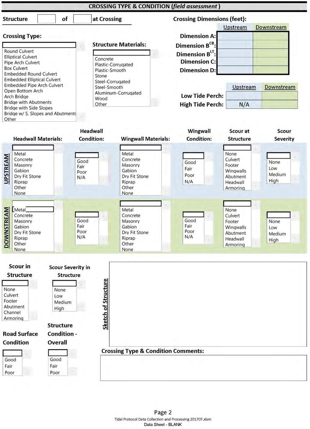
71 66
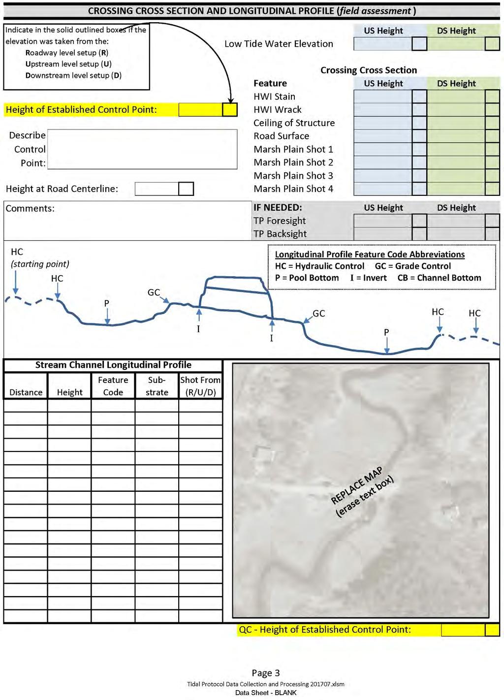
72 67
73 68
74 69
75 70
76 Appendix B: Wetlands and Deepwater Habitats Classification 71
77 72
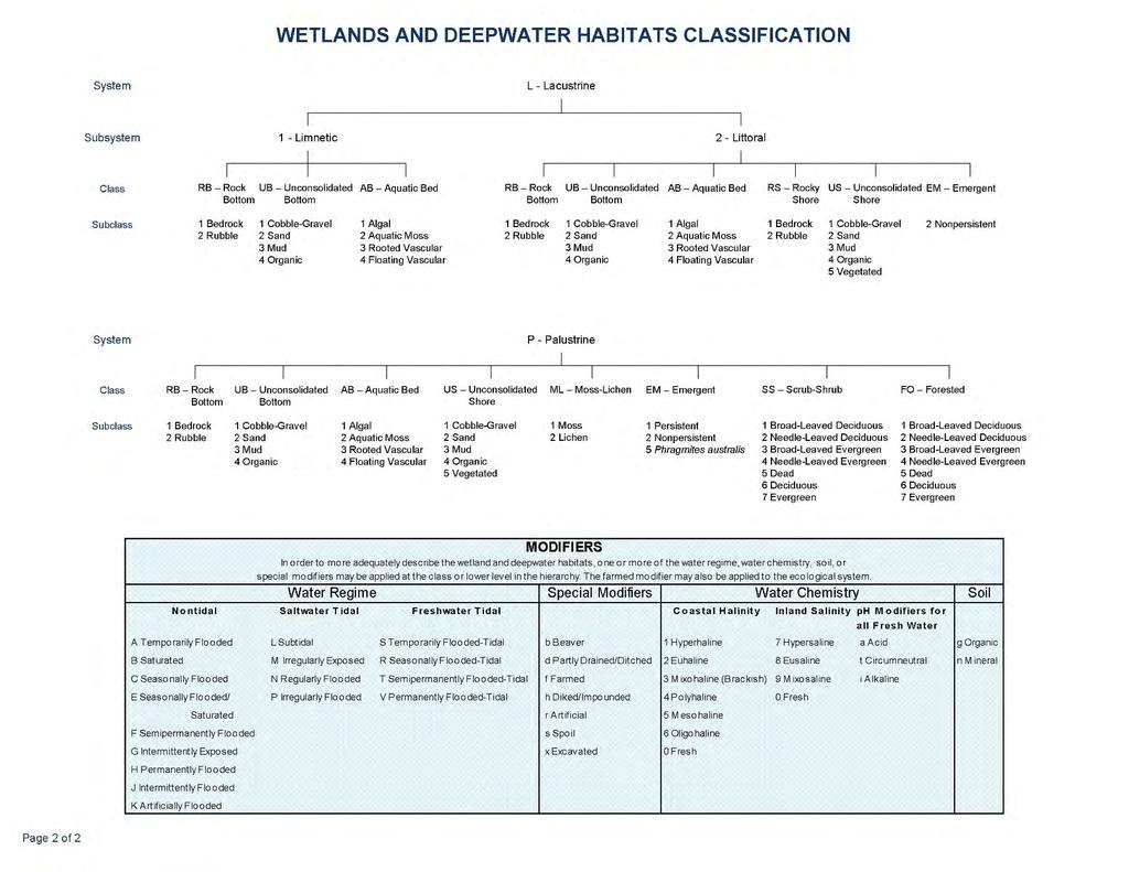
78 73
Great Lakes Stream Crossing Inventory Instructions
 Great Lakes Stream Crossing Inventory Instructions This document is a guide to completing the Stream Crossing Data Sheet (2/28/11 version). Careful attention to this guidance will ensure consistent crossing
Culvert Design for Low and High Gradient Streams in the Midwest. Dale Higgins, Hydrologist Chequamegon-Nicolet National Forest
 Culvert Design for Low and High Gradient Streams in the Midwest Dale Higgins, Hydrologist Chequamegon-Nicolet National Forest Overview Culvert Design Considerations Hydraulic Terms Culvert Impacts Low
Massachusetts Stream Crossing Case Studies
 Massachusetts Stream Crossing Case Studies Amy Singler Associate Director, River Restoration Program Carrie Banks River Continuity Coordinator Case Studies: Public Benefits: Movement of goods and people
(Revised February,2005) CULVERTS, BRIDGES, AND FORDS
 CULVERTS, BRIDGES, AND FORDS") GUIDE TO STREAM CROSSINGS (Revised February,2005) CULVERTS, BRIDGES, AND FORDS Culverts, bridges, and fords are all methods used to cross-streams. Culverts are the most common stream crossing structure.
GUIDE TO STREAM CROSSINGS (Revised February,2005) CULVERTS, BRIDGES, AND FORDS Culverts, bridges, and fords are all methods used to cross-streams. Culverts are the most common stream crossing structure.
Culvert Design An Overview of the NYS Highway Design Manual Chapter 8
 Seventeenth Statewide Conference on Local Bridges Culvert Design An Overview of the NYS Highway Design Manual Chapter 8 Tuesday, October 25, 2011 Training Session: Culvert Design, Analysis - talk 2 Presented
OFFICE OF STRUCTURES MANUAL FOR HYDROLOGIC AND HYDRAULIC DESIGN CHAPTER 11 APPENDIX B TIDEROUT 2 USERS MANUAL
 OFFICE OF STRUCTURES MANUAL FOR HYDROLOGIC AND HYDRAULIC DESIGN CHAPTER 11 APPENDIX B TIDEROUT 2 USERS MANUAL APRIL 2011 APRIL 2011 Page 1 Preface TIDEROUT 2, Build 1.22 dated June 29, 2006 is the current
Assessing Ecosystem Impacts from Road Stream Crossings through Community Involvement
 Assessing Ecosystem Impacts from Road Stream Crossings through Community Involvement Background Why is the NH Fish and Game Department interested in culverts? Block fish migration Reduce opportunities
Fish Passage Assessment Report Mare Brook Culverts
 Fish Passage Assessment Report Mare Brook Culverts Fish Passage Assessment Component of Mare Brook Watershed Assessment and Community Engagement Project Prepared for: FB Environmental Associates 97A Exchange
FISH PASSAGE IMPROVEMENT in California s Watersheds. Assessments & Recommendations by the Fish Passage Forum
 FISH PASSAGE IMPROVEMENT in California s Watersheds Assessments & Recommendations by the Fish Passage Forum FISH PASSAGE IMPROVEMENT in California s Watersheds The mission of the Fish Passage Forum is
FINAL REPORT. Yonkers Creek Migration Barrier Removal Project Wonderstump Road Del Norte County. Submitted By:
 FINAL REPORT Yonkers Creek Migration Barrier Removal Project Wonderstump Road Del Norte County Submitted By: Del Norte County Community Development Department Yonkers Creek Migration Barrier Removal Project
Building Coastal Resiliency at Plymouth Long Beach
 Building Coastal Resiliency at Plymouth Long Beach Department of Marine and Environmental Affairs March 30, 2017 Introducing Green Infrastructure for Coastal Resiliency Plymouth Long Beach & Warren s Cove
Tide Gate Modifications for Fish Passage and Water Quality Enhancement
 Tide Gate Modifications for Fish Passage and Water Quality Enhancement Tillamook Bay National Estuary Project 613 Commercial St. PO Box 493 Garibaldi, OR 97118 Phone (503) 322-2222 Fax (503) 322-2261 Jay
APPENDIX C. Fluvial and Tidal Hydraulics Report
 APPENDIX C Fluvial and Tidal Hydraulics Report BUENA VISTA LAGOON ENHANCEMENT PROJECT FLUVIAL AND TIDAL HYDRAULICS ANALYSES Prepared for: SANDAG 401 B Street, Suite 800 San Diego, California 92101 Contact:
UNDERWATER BRIDGE INSPECTION REPORT STRUCTURE NO CSAH 133 OVER A DITCH ST. LOUIS COUNTY
 UNDERWATER BRIDGE INSPECTION REPORT STRUCTURE NO. 7780 CSAH 133 OVER A DITCH ST. LOUIS COUNTY SEPTEMBER 27, 2012 PREPARED FOR THE MINNESOTA DEPARTMENT OF TRANSPORTATION BY COLLINS ENGINEERS, INC. JOB NO.
APPENDIX C VEGETATED EMERGENCY SPILLWAY. VERSION 1.0 March 1, 2011
 APPENDIX C VEGETATED EMERGENCY SPILLWAY VERSION 1.0 March 1, 2011 [NOTE: Could use a better photo more clearly showing the emergency spillway in the context of the dam.] SECTION C-1: DESCRIPTION OF PRACTICE
UPPER BEACH REPLENISHMENT PROJECT RELATED
 ASSESSMENT OF SAND VOLUME LOSS at the TOWNSHIP of UPPER BEACH REPLENISHMENT PROJECT RELATED to the LANDFALL OF HURRICANE SANDY - PURSUANT TO NJ-DR 4086 This assessment is in response to Hurricane Sandy
Chadbourne Dam Repair and Fish Barrier
 Chadbourne Dam Repair and Fish Barrier Final Report for the Western Native Trout Initiative Prepared by: Carol Endicott Yellowstone Cutthroat Trout Conservation Biologist Montana Fish, Wildlife & Parks
APPENDIX J HYDROLOGY AND WATER QUALITY
 APPENDIX J HYDROLOGY AND WATER QUALITY J-1 Technical Report on Airport Drainage, Northern Sector Airport and Ordinance Creek Watershed / Preliminary Creek Constructed Natural Channel Culvert J-2 Preliminary
Annex E Bridge Pier Protection Plan
 Annex E Bridge Pier Protection Plan Table E1 Bridge Types and Locations Table E2 Flow Conditions For River Sections Figure E1 Bridge Abutment Protection Figure E2 Bridge Pier Protection Figure E3 Central
Little Traverse Bay Watershed Road/Stream Crossing Inventory
 Little Traverse Bay Watershed Road/Stream Crossing Inventory Completed by Tip of the Mitt Watershed Council with support from: Petoskey-Harbor Springs Area Community Foundation s Little Traverse Bay Protection
Outlet Structures T-12
 Description This section provides guidance and details for outlet structures for use primarily with BMPs utilizing sedimentation, (i.e., extended detention basins (EDBs), retention ponds, and constructed
Aquatic Organism Passage at Road-Stream Crossings CHUCK KEEPORTS FOREST HYDROLOGIST ALLEGHENY NATIONAL FOREST WARREN, PENNSYLVANIA
 Aquatic Organism Passage at Road-Stream Crossings CHUCK KEEPORTS FOREST HYDROLOGIST ALLEGHENY NATIONAL FOREST WARREN, PENNSYLVANIA TOPICS COVERED Aquatic Organism Passage (AOP) Benefits of AOP Crossings
Estuarine Shoreline Stabilization
 Estuarine Shoreline Stabilization Property Owner s Guide to Determining the Most Appropriate Stabilization Method Estuarine shorelines are dynamic features that experience continued erosion. Land is lost
Creek Trash Assessment (CTA) Methodology (Demonstration: Mill Run Creek, Cheltenham, Pa.)
 Methodology (Demonstration: Mill Run Creek, Cheltenham, Pa.)") Creek Trash Assessment (CTA) Methodology (Demonstration: Mill Run Creek, Cheltenham, Pa.) Mill Run Creek emerges from a storm sewer in Philadelphia to an open creek in Cheltenham. The Creek downstream
Creek Trash Assessment (CTA) Methodology (Demonstration: Mill Run Creek, Cheltenham, Pa.) Mill Run Creek emerges from a storm sewer in Philadelphia to an open creek in Cheltenham. The Creek downstream
SELBY CREEK SILVERADO TRAIL CULVERT FISH PASSAGE ASSESSMENT
 SELBY CREEK SILVERADO TRAIL CULVERT FISH PASSAGE ASSESSMENT NAPA COUNTY, CALIFORNIA PREPARED BY NAPA COUNTY RESOURCE CONSERVATION DISTRICT 1303 JEFFERSON ST. SUITE 500B NAPA, CALIFORNIA 94559 WWW.NAPARCD.ORG
Chagrin River TMDL Appendices. Appendix F
 Appendix F The following are excerpts from the Eastern Brook Trout Joint Venture s Conservation Strategy (Working Draft v.6), Conserving the Eastern Brook Trout: Strategies for Action Found at: http://www.easternbrooktrout.org/constrategy.html
Evaluation of June 9, 2014 Federal Emergency Management Agency Flood Insurance Study for Town of Weymouth, Norfolk, Co, MA
 Evaluation of June 9, 2014 Federal Emergency Management Agency Flood Insurance Study for Town of Weymouth, Norfolk, Co, MA Prepared For: Woodard & Curran 95 Cedar Street, Suite 100 Providence, RI 02903
Project Report for Marsh Creek and Albion River Instream Fish Barrier Removal Flynn Creek Road, CR 135, M.P. 8.1 and 8.3
 Project Report for Marsh Creek and Albion River Instream Fish Barrier Removal Flynn Creek Road, CR 135, M.P. 8.1 and 8.3 Project Title: Marsh Creek and Albion River Instream Fish Barrier Removal, Flynn
LOCAL COASTAL PROGRAM UPDATE
 LOCAL COASTAL PROGRAM UPDATE Agenda Meeting #1 General Information (1 1:45 pm) Introductions and Background Grants involved What is a Local Coastal Program? What is required? LCP Update tasks and schedule
OFFICE OF STRUCTURES MANUAL FOR HYDROLOGIC AND HYDRAULIC DESIGN CHAPTER 13 CULVERTS APRIL 2011
 OFFICE OF STRUCTURES MANUAL FOR HYDROLOGIC AND HYDRAULIC DESIGN CHAPTER 13 CULVERTS APRIL 2011 APRIL 2011 Chapter 13 Culverts Table of Contents Foreword.3 13.1 Introduction.. 4 13.2 Policy 6 13.3 Passage
Earthen Embankments. turning into larger, more costly repairs. The following. The State Dam Safety Program has inspection
 TOPIC: COMMON PROBLEMS FOR SMALL DAMS WITH CONCRETE CHANNEL SPILLWAYS The State Dam Safety Program has inspection requirements for state regulated dams. A dam, like any man-made structure, will change
Chapter 11. Culverts and Bridges Design Checklist for Culvert Design
 Yes No N/A Design Requirements I. GENERAL DESIGN GUIDELINES Chapter 11. Culverts and Bridges A. Culvert design is in accordance with the Culverts chapter of Volume 2 of the UDFCD Manual for additional
RE: Hurricane Matthew Beach Damage Assessment and Recommendations [CSE 2416]
![RE: Hurricane Matthew Beach Damage Assessment and Recommendations [CSE 2416]](/thumbs/83/87675702.jpg "RE: Hurricane Matthew Beach Damage Assessment and Recommendations [CSE 2416]") October 25, 2016 Iris Hill Town Administrator Town of Edisto Beach 2414 Murray St Edisto Beach SC 29438 RE: Hurricane Matthew Beach Damage Assessment and Recommendations [CSE 2416] Dear Iris, Hurricane
October 25, 2016 Iris Hill Town Administrator Town of Edisto Beach 2414 Murray St Edisto Beach SC 29438 RE: Hurricane Matthew Beach Damage Assessment and Recommendations [CSE 2416] Dear Iris, Hurricane
HURRICANE SANDY LIMITED REEVALUATION REPORT UNION BEACH, NEW JERSEY DRAFT ENGINEERING APPENDIX SUB APPENDIX D SBEACH MODELING
 HURRICANE SANDY LIMITED REEVALUATION REPORT UNION BEACH, NEW JERSEY DRAFT ENGINEERING APPENDIX SUB APPENDIX D SBEACH MODELING Rev. 18 Feb 2015 1 SBEACH Modeling 1.0 Introduction Following the methodology
UNDERWATER BRIDGE INSPECTION REPORT STRUCTURE NO CSAH 4 OVER THE BEAVER RIVER ST. LOUIS COUNTY
 UNDERWATER BRIDGE INSPECTION REPORT STRUCTURE NO. 7635 CSAH 4 OVER THE BEAVER RIVER ST. LOUIS COUNTY JUNE 18, 2012 PREPARED FOR THE MINNESOTA DEPARTMENT OF TRANSPORTATION BY COLLINS ENGINEERS, INC. JOB
TOP:001.3 U.S. Fish and Wildlife Service TECHNICAL OPERATING PROCEDURE
 TOP:001.3 March 12, 2015 U.S. Fish and Wildlife Service Marquette Biological Station 3090 Wright Street Marquette, Michigan 49855 U.S.A. and U.S. Fish and Wildlife Service Ludington Biological Station
HEC 26 Aquatic Organism Passage Design Manual Evolution & Application
 HEC 26 Aquatic Organism Passage Design Manual Evolution & Application Sven Leon, P.E., Hydraulics Engineer Federal Highway Administration 2015 Alaska Fish Passage Meeting October 13 14, 2015 VTRC, Juneau,
UNDERWATER BRIDGE INSPECTION REPORT STRUCTURE NO CSAH NO. 7 OVER THE SNAKE RIVER DISTRICT 1 - PINE COUNTY
 UNDERWATER BRIDGE INSPECTION REPORT STRUCTURE NO. 58506 CSAH NO. 7 OVER THE SNAKE RIVER DISTRICT 1 - PINE COUNTY PREPARED FOR THE MINNESOTA DEPARTMENT OF TRANSPORTATION BY COLLINS ENGINEERS, INC. JOB NO.
UNDERWATER BRIDGE INSPECTION REPORT DISTRICT 4 - OTTER TAIL COUNTY
 UNDERWATER BRIDGE INSPECTION REPORT STRUCTURE NO. L0885 TWP NO. 970 OVER THE OTTER TAIL RIVER DISTRICT 4 - OTTER TAIL COUNTY PREPARED FOR THE MINNESOTA DEPARTMENT OF TRANSPORTATION BY COLLINS ENGINEERS,
Technical Report Culvert A Hydraulic Analysis
 DATE: November 3, 2011 Technical Report Culvert A Hydraulic Analysis TO: FROM: RE: Jim Reiser, P.E. Project Manager Parsons Brinckerhoff, Inc. Kurt Killian, P.E., CFM Parsons Brinckerhoff, Inc. Design
Presented by Fred Halterman, URS Jennie Agerton, URS
 Presented by Fred Halterman, URS Jennie Agerton, URS What is Eco Friendly Culvert Design? Culvert design that: Maintains connectivity for aquatic organism migration Maintains connectivity for gene flow
Interim Guidance Fish Presence Absence
 Interim Guidance Fish Presence Absence Source: Forest Practices Act Guidance for Division 635 of the forest practices act dealing with stream classification when no fish surveys have been done (referenced
Simulating Streams Through Culverts in Mat-Su, Alaska
 Simulating Streams Through Culverts in Mat-Su, Alaska Project Managers Bill Rice, P.E., USFWS Hydrologist Mary Price, USFWS Fishery Biologist The Team Approach US Fish and Wildlife Service Bill Rice, P.E.,
Big Spring Creek Habitat Enhancement and Fishery Management Plans
 Big Spring Creek Habitat Enhancement and Fishery Management Plans November 5, 2012 Big Spring Events and Activities Center Newville, PA Charlie McGarrell Regional Habitat Biologist Pennsylvania Fish and
Delaware Chapter Surfrider Foundation - Indian River Inlet Monitoring
 Delaware Chapter Surfrider Foundation - Indian River Inlet Monitoring In 2012, the Delaware Surfrider Foundation Chapter formed the Surf Quality and Access Committee to focus on issues such as surf spot
General Information for Culvert Design
 Design Manual Chapter 2 - Stormwater 2E - Culvert Design 2E-1 General Information for Culvert Design A. Introduction A culvert is a conduit under an embankment that transports stormwater from one side
BC Ministry of Forests. March Fish Stream Crossing Guidebook. Forest Practices Code of British Columbia.
 FRST 557 Lecture 7c Bridges and Culverts: Water Velocity and Discharge Lesson Background and Overview: The previous two lessons presented methods for estimating water volume flow at a particular site and
Kennebunk River Road-Stream Crossing Survey Prepared by: Wells National Estuarine Research Reserve 342 Laudholm Farm Road Wells, Maine 04090
 Kennebunk River Road-Stream Crossing Survey 2010 Prepared by: Wells National Estuarine Research Reserve 342 Laudholm Farm Road Wells, Maine 04090 Acknowledgements The 2010 Kennebunk River Road-Stream
Illinois State Water Survey
 Illinois State Water Survey HYDROLOGY DIVISION SWS Contract Report 508 COMPARISON OF 1987 AND 1989 BED PROFILE SURVEYS OF THE LOWER CACHE RIVER by Richard Allgire Office of Sediment and Wetland Studies
PLACEMENT OF SIGNS RECOMMENDED PRACTICES SUB-SECTION
 Page 1 of 6 RECOMMENDED PRACTICES PART SECTION SUB-SECTION HIGHWAY SIGNS GENERAL General Proper positioning of signs is an important element in the overall control of traffic within a roadway network.
Project Webpage:
 Project Webpage: http://nature.ly/marinesatlanticbightera Coastal Data and Full Metadata: http://easterndivision.s3.amazonaws.com/marine/sab MA/SABMACoastalEcosystems.zip Coastal Chapter: http://easterndivision.s3.amazonaws.com/marine/sab
Hydraulic Modeling of Stream Enhancement Methods
 Hydraulic Modeling of Stream Enhancement Methods Matthew J. Curry John J. Levitsky Abstract Development within watersheds increases the amounts of runoff causing stream erosion and degradation of stream
Plan B Dam Breach Assessment
 Plan B Dam Breach Assessment Introduction In support of the Local Sponsor permit applications to the states of Minnesota and North Dakota, a dam breach analysis for the Plan B alignment of the Fargo-Moorhead
FISH PASSAGE ALTERNATIVES ANALYSIS ON PENNYPACK CREEK AT VERREE ROAD DAM AND ROOSEVELT BOULEVARD DAM PHILADELPHIA, PENNSYLVANIA
 FISH PASSAGE ALTERNATIVES ANALYSIS ON PENNYPACK CREEK AT VERREE ROAD DAM AND ROOSEVELT BOULEVARD DAM PHILADELPHIA, PENNSYLVANIA Prepared for: One Parkway, 10 th Floor 1515 Arch Street Philadelphia, PA
Figure 4, Photo mosaic taken on February 14 about an hour before sunset near low tide.
 The Impact on Great South Bay of the Breach at Old Inlet Charles N. Flagg and Roger Flood School of Marine and Atmospheric Sciences, Stony Brook University Since the last report was issued on January 31
Alewife Brook, Cape Elizabeth, River Herring Monitoring Summary 2015
 University of Southern Maine USM Digital Commons Publications Casco Bay Estuary Partnership (CBEP) 2-3-2016 Alewife Brook, Cape Elizabeth, River Herring Monitoring Summary 2015 Matt Craig University of
Eastern Brook Trout Joint Venture Annual Report The Nature Conservancy 2013
 Eastern Brook Trout Joint Venture Annual Report The Nature Conservancy 2013 2013 Annual Performance Report Enhancing Connectivity in the Ash-Black Rock Sub-basin of the West Branch Narraguagus River. Project
Storm Damage Floating Culverts & Other Inlet Issues
 Storm Damage Floating Culverts & Other Inlet Issues Mark Bailey, PE - Hydraulic Manager, INDOT Dale Sedler, PE - Sr. Hydraulic Engineer, INDOT Road School 2016 What causes a culvert to float? 1. Accumulation
Figure 1. Schematic illustration of the major environments on Mustang Island.
 STOP #1: PACKERY CHANNEL BEACH TO BAY We will start this field guide near the north jetty of Packery Channel and hike across the island to Corpus Christi Bay (fig. 1). The island emerges from the Gulf
Indiana LTAP Road Scholar Core Course #10 Culvert Drainage. Presented by Thomas T. Burke, Jr., PhD, PE Christopher B. Burke Engineering, Ltd.
 Indiana LTAP Road Scholar Core Course #10 Culvert Drainage Presented by Thomas T. Burke, Jr., PhD, PE Christopher B. Burke Engineering, Ltd. Objectives Review culvert shapes, end sections, and materials
Washington State Fish Passage Barrier Removal Projects. Casey Kramer, PE WSDOT State Hydraulics Engineer
 Washington State Fish Passage Barrier Removal Projects Casey Kramer, PE WSDOT State Hydraulics Engineer 2014 National Hydraulic Engineering Conference Iowa City, IA August 20 th, 2014 WSDOT Fish Passage
UNDERWATER BRIDGE INSPECTION REPORT DISTRICT 4 - OTTER TAIL COUNTY
 UNDERWATER BRIDGE INSPECTION REPORT STRUCTURE NO. L0885 TWP NO. 970 OVER THE OTTER TAIL RIVER DISTRICT 4 - OTTER TAIL COUNTY PREPARED FOR THE MINNESOTA DEPARTMENT OF TRANSPORTATION BY COLLINS ENGINEERS,
JAP Additional Information Sheet
 JAP Additional Information Sheet Block 15: Purpose and Need The USACE purpose of the project is to provide a safe and reliable whitewater park for the recreational public in a city park, which will provide
The Cumulative Impacts of Shoreline Armoring on Forage Fish Spawning Habitat in San Juan County, Washington
 Western Washington University Western CEDAR Salish Sea Ecosystem Conference 2014 Salish Sea Ecosystem Conference (Seattle, Wash.) May 1st, 1:30 PM - 3:00 PM The Cumulative Impacts of Shoreline Armoring
STREAM SURVEY File form No..
 scanned for KRIS THE RESOURCES AGENCY OF CALIFORNIA California Department of Fish and Game STREAM SURVEY File form No.. Date: September 4, 1969. NAME: North Fork Schooner Gulch Creek COUNTY: Mendocino.
If you have comments on this or suggestions for other terms that should be added to this glossary, please send an to
 Tide Gates Glossary There is very little information available anywhere related to tide gates and flap gates. This is a glossary of terms that are associated with, or useful when discussing, tide gates.
Sea-Level Rise and Coastal Habitats in Southeastern Louisiana An Application of the SLAMM Model
 Sea-Level Rise and Coastal Habitats in Southeastern Louisiana An Application of the SLAMM Model Patty Glick (National Wildlife Federation) Jonathan Clough (Warren Pinnacle Consulting, Inc.) Amy Polaczyk
Assessment of Baseline Geomorphic Features at. Proposed Stream Crossings On The Proposed County Road 595. Marquette County, Michigan
 Assessment of Baseline Geomorphic Features at Proposed Stream Crossings On The Proposed County Road 595 Marquette County, Michigan Prepared for: Kennecott Eagle Minerals Company Marquette, Michigan Prepared
CHAPTER 4 DESIRED OUTCOMES: VISION, GOALS, AND OBJECTIVES
 CHAPTER 4 DESIRED OUTCOMES: VISION, GOALS, AND OBJECTIVES Vision One of the first steps in developing this Plan was articulating a vision - a clear statement of what the Plan strives to achieve and what
Welcome to Paddle for the Edge!
 Welcome to Paddle for the Edge! Thank you for volunteering to conduct a survey of the Barnegat Bay s shorelines. As a citizen scientist, you become part of a project to collect critical data about current
UNDERWATER BRIDGE INSPECTION REPORT STRUCTURE NO CSAH NO. 101 OVER THE MINNESOTA RIVER DISTRICT 8 - REDWOOD COUNTY
 UNDERWATER BRIDGE INSPECTION REPORT STRUCTURE NO. 7149 CSAH NO. 101 OVER THE MINNESOTA RIVER DISTRICT 8 - REDWOOD COUNTY PREPARED FOR THE MINNESOTA DEPARTMENT OF TRANSPORTATION BY COLLINS ENGINEERS, INC.
Hydraulic Modeling Analysis
 Final Report Photograph: http://www.newington-dover.com Newington to Dover, New Hampshire Prepared for: Vanasse Hangen Brustlin, Inc. 6 Bedford Farms Drive, Suite 607 Bedford, New Hampshire 03110-6532
CALCASIEU SALINITY STRUCTURES. HYDRODYNAMIC MODELING (To Support Design of Salinity Barriers)
") CALCASIEU SALINITY STRUCTURES HYDRODYNAMIC MODELING (To Support Design of Salinity Barriers) Presentation Overview 1 2 3 4 5 Project Overview and CEA Circulation Modeling Vessel Hydrodynamics Modeling
CALCASIEU SALINITY STRUCTURES HYDRODYNAMIC MODELING (To Support Design of Salinity Barriers) Presentation Overview 1 2 3 4 5 Project Overview and CEA Circulation Modeling Vessel Hydrodynamics Modeling
Discussion on the Selection of the Recommended Fish Passage Design Discharge
 Discussion on the Selection of the Recommended Fish Passage Design Discharge Introduction The provision of fish passage is a requirement for most proposed culvert and bridge installations in Alberta, depending
Fish Friendly Crossings- Examples from Nash Stream
 Fish Friendly Crossings- Examples from Nash Stream Maggie Machinist- North Regional Forester, Division of Forests and Lands. Nash Stream Nash Stream Forest is 40,000 acres, owned and managed by NH Division
Chapter 10 Lecture Outline. The Restless Oceans
 Chapter 10 Lecture Outline The Restless Oceans Focus Question 10.1 How does the Coriolis effect influence ocean currents? The Ocean s Surface Circulation Ocean currents Masses of water that flow from one
Five Counties Salmonid Conservation Program - Fish Passage Design Workshop. February 2013
 Program - Aquatic Organisms and Stream Crossings Ecological Connectivity A watershed is a network of channels that drain a common boundary. Channel characteristics formed by interaction of precipitation,
Conserving the Forests, Lakes and Streams of Northeast Michigan
 4241 Old US 27 South, Suite 2, Gaylord, Michigan 49735 (989) 448-2293 www.huronpines.org info@huronpines.org Prioritized Restoration Projects in the AuSable River Watershed Summer 2015 Update from Huron
Feasibility Study for Restoration of Titlow Lagoon Fish Passage. South Puget Sound Salmon Enhancement Group
 Feasibility Study for Restoration of Titlow Lagoon Fish Passage South Puget Sound Salmon Enhancement Group January 2010 Feasibility Study for Restoration of Titlow Lagoon Fish Passage Prepared for South
Sussex County, DE Preliminary Study Overview
 Sussex County, DE Preliminary Study Overview Coastal study scope: 102 miles of entire County shoreline Revised 102 panels for coastal study Riverine study scope: 14 streams, 67.1 miles, within the Nanticoke
page - Laboratory Exercise #5 Shoreline Processes
 page - Laboratory Exercise #5 Shoreline Processes Section A Shoreline Processes: Overview of Waves The ocean s surface is influenced by three types of motion (waves, tides and surface currents). Shorelines
Understanding the Impacts of Culvert Performance on Stream Health
 Understanding the Impacts of Culvert Performance on Stream Health Kristin Thomas Aquatic Ecologist Michigan Trout Unlimited Transportation and the Environment Conference 12/5/2018 Importance of adequately
SPO Regional Challenge Grant Creation of a Sea Level Adaption Working Group for Biddeford, Saco, OOB and Scarborough J.T. Lockman, AICP, Planning
 SPO Regional Challenge Grant Creation of a Sea Level Adaption Working Group for Biddeford, Saco, OOB and Scarborough J.T. Lockman, AICP, Planning Director Southern Maine Regional Planning Commission jlockman@smrpc.org
CALIFORNIA SALMONID STREAM HABITAT RESTORATION MANUAL APPENDIX IX-A CULVERT CRITERIA FOR FISH PASSAGE INTRODUCTION
 APPENDIX IX-A STATE OF CALIFORNIA RESOURCES AGENCY DEPARTMENT OF FISH AND GAME CULVERT CRITERIA FOR FISH PASSAGE For habitat protection, ecological connectivity should be a goal of stream-road crossing
GONE! Coastal Erosion Happens During Storms! Why Worry About Coastal Setbacks? Goals for Today
 RI Regulatory Setbacks & Buffers: Coastal Zone Management Issues New England Onsite Wastewater Training Program @ URI OWT 155 November 21, 2013 Goals for Today Understand the impacts of storms, coastal
ADDENDA B Hydrologic and Hydraulic (H&H) Study Guidance 2019
 Study Guidance 2019") 09/25/2018 DRAFT FEMA Region I PA H&H Study ADDENDA B Hydrologic and Hydraulic (H&H) Study Guidance 2019 Region I Federal Emergency Management Agency (FEMA) Public Assistance Hydrologic and Hydraulic (H&H)
09/25/2018 DRAFT FEMA Region I PA H&H Study ADDENDA B Hydrologic and Hydraulic (H&H) Study Guidance 2019 Region I Federal Emergency Management Agency (FEMA) Public Assistance Hydrologic and Hydraulic (H&H)
APPENDIX K CULVERT INSPECTION MEMO
 APPENDIX K CULVERT INSPECTION MEMO McCORMICK RANKIN CORPORATION 2655 North Sheridan Way Mississauga, Ontario, L5K 2P8 Tel: (905)823-8500 Fax: (905) 823-8503 E-mail: mrc@mrc.ca Website: www.mrc.ca MEMO
CHAPTER 8 ASSESSMENT OF COASTAL VULNERABILITY INDEX
 124 CHAPTER 8 ASSESSMENT OF COASTAL VULNERABILITY INDEX 8.1 INTRODUCTION In order to assess the vulnerability of the shoreline considered under this study against the changing environmental conditions,
Lecture Outlines PowerPoint. Chapter 15 Earth Science, 12e Tarbuck/Lutgens
 Lecture Outlines PowerPoint Chapter 15 Earth Science, 12e Tarbuck/Lutgens 2009 Pearson Prentice Hall This work is protected by United States copyright laws and is provided solely for the use of instructors
HY-8 Version 7.2 Build Date January 17, Federal Highway Administration.
 HY-8 Version 7.2 Build Date January 17, 2012 Federal Highway Administration http://www.fhwa.dot.gov/engineering/hydraulics/software/hy8/index.cfm SIMPLE Simple to use Use for simple culverts and bridges
Sediment Basin 7E-12. Design Manual Chapter 7 - Erosion and Sediment Control 7E - Design Information for ESC Measures BENEFITS.
 7E-12 Design Manual Chapter 7 - Erosion and Sediment Control 7E - Design Information for ESC Measures Sediment Basin BENEFITS Flow Control Erosion Control Sediment Control Runoff Reduction Flow Diversion
Boothbay Harbor Rotary Club May 12, 2016
 Mapping Potential Sea Level Rise and Storm Surge in Boothbay Harbor, ME Boothbay Harbor Rotary Club May 12, 2016 Peter A. Slovinsky, Marine Geologist Maine Geological Survey S.M. Dickson, MGS Quickly,
Minnesota Department of Natural Resources Division of Fish and Wildlife Section of Fisheries. Stream Survey Report. Luxemburg Creek.
 Minnesota F-29-R(P)-24 Area 315 Study 3 March 2016 Minnesota Department of Natural Resources Division of Fish and Wildlife Section of Fisheries Stream Survey Report Luxemburg Creek 2015 Mark Pelham Sauk
Maryland Chapter Trout Unlimited Brook Trout Conservation Effort
 Maryland Chapter Trout Unlimited Brook Trout Conservation Effort Photo by Matt Kline Portfolio of Recent Work MDTU Brook Trout Conservation Coordinator: Scott C. Scarfone, ASLA sscarfone@oasisdesigngroup.com
APPENDIX B HYDRAULIC DESIGN DATA FOR CULVERTS
 TM 5-820-4/AFM 88-5, Chap 4 APPENDIX B HYDRAULIC DESIGN DATA FOR CULVERTS B-1. General. a. This appendix presents diagrams, charts, coefficients and related information useful in design of culverts. The
Access Management Standards
 Access Management Standards Section 1: Application of Access Standards This chapter describes the Department's access management standards for access connections on the county roadway system. The standards
CHAPTER 4 SPALDING COUNTY, GEORGIA 4.0 CULVERT DESIGN
 SPALDING COUNTY, GEORGIA CHAPTER 4 4.0 CULVERT DESIGN... 4-1 4.1 INTRODUCTION... 4-1 4.2 SYMBOLS AND DEFINITIONS... 4-1 4.3 ENGINEERING DESIGN CRITERIA... 4-2 4.3.1 FREQUENCY FLOOD... 4-2 4.3.2 VELOCITY
2016 NC Coastal Local Governments Annual Meeting
 2016 NC Coastal Local Governments Annual Meeting Coastal Flood Study Modeling and Mapping 101 April 21, 2016 Tom Langan, PE, CFM Engineering Supervisor NCEM Floodplain Mapping Program FEMA Coastal Flood
REVETMENTS. Purposes and Operational Constraints. Purposes Erosion control o o. Revetment Design 4/5/2016. CE A676 Coastal Engineering
 REVETMENTS Ijsseldam, the Netherlands Orson P. Smith, PE, Ph.D. Instructor Purposes and Operational Constraints Purposes Erosion control o o Embankment Toe protection for a seawall, retaining wall or other
UNDERWATER BRIDGE INSPECTION REPORT DISTRICT 1 PINE COUNTY
 UNDERWATER BRIDGE INSPECTION REPORT STRUCTURE NO. 58551 CSAH NO. 41 OVER THE KETTLE RIVER DISTRICT 1 PINE COUNTY JULY 28, 2012 PREPARED FOR THE MINNESOTA DEPARTMENT OF TRANSPORTATION BY COLLINS ENGINEERS,